Embed Size (px)
Citation preview

Chilled Water DOAS Fan Powered Terminal Units
CHILLED WATER DOAS FAN POWERED TERMINAL UNITS
DOAS TERMINAL UNITS FEATURES AND BENEFITS
MINIMUM VENTILATION CONTROL
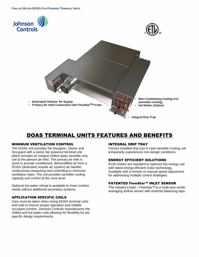
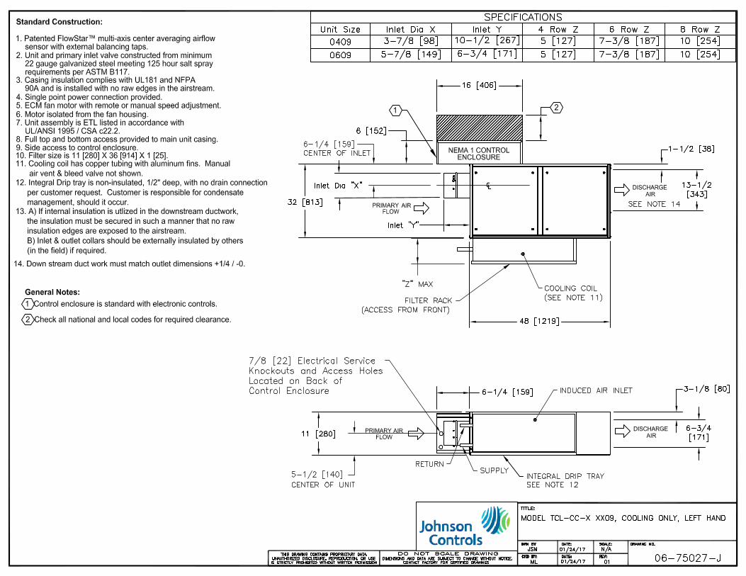
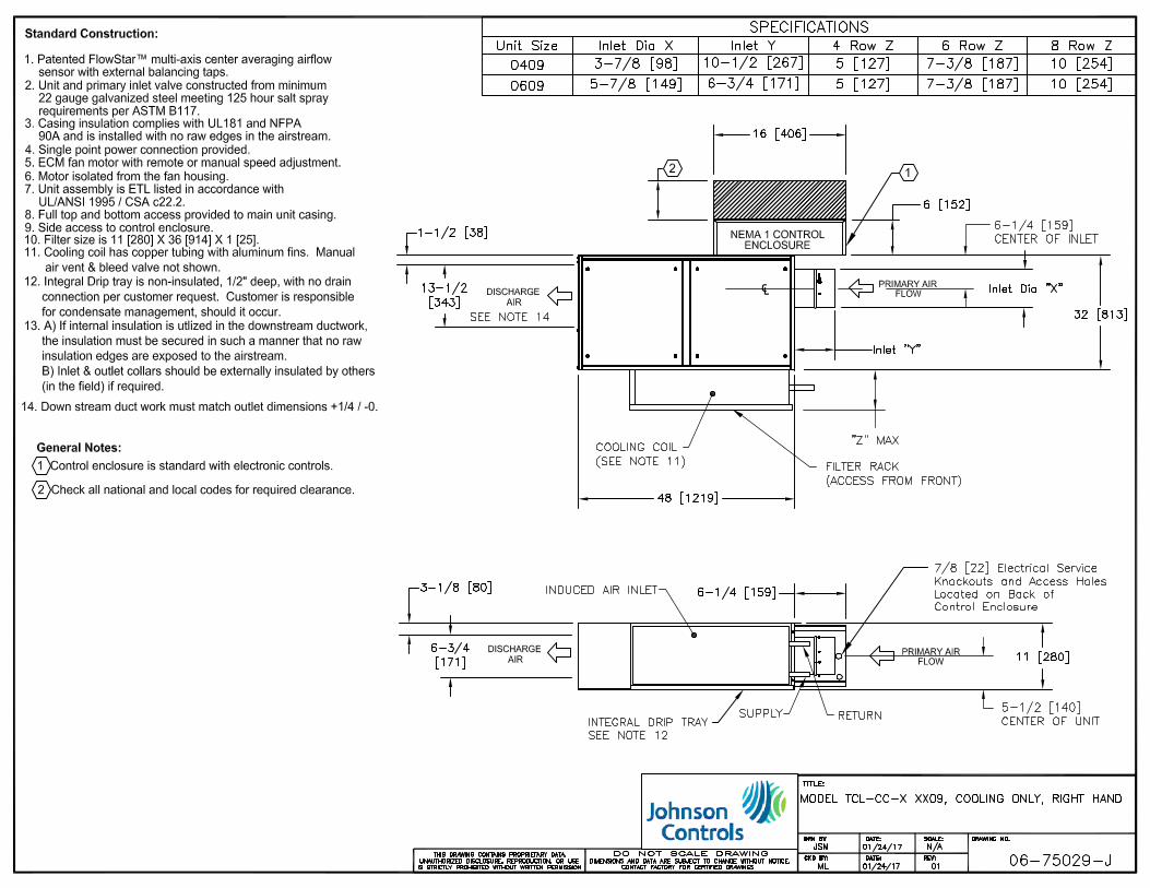
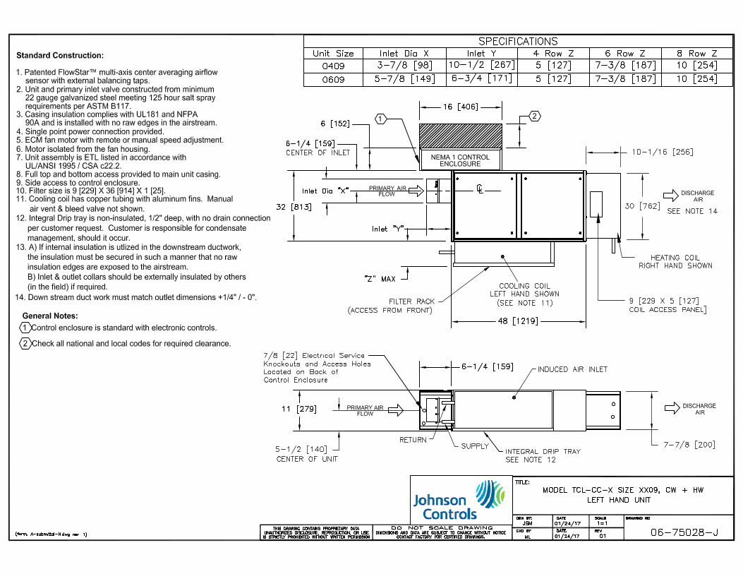
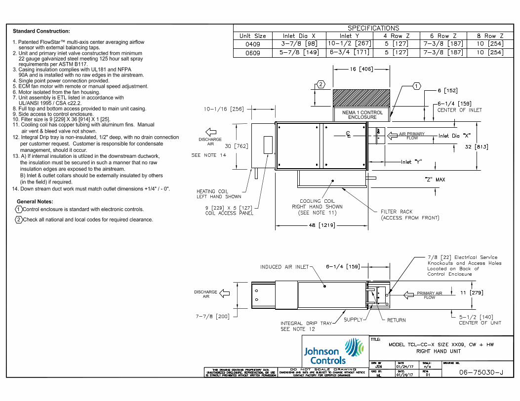
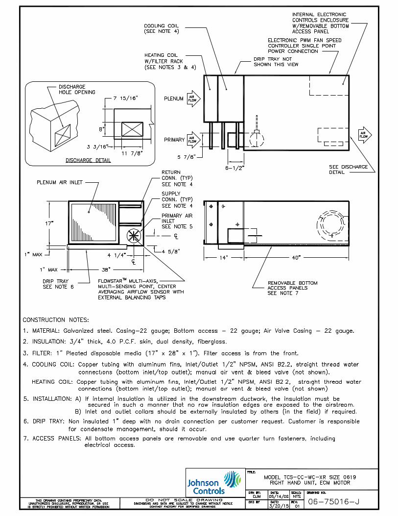
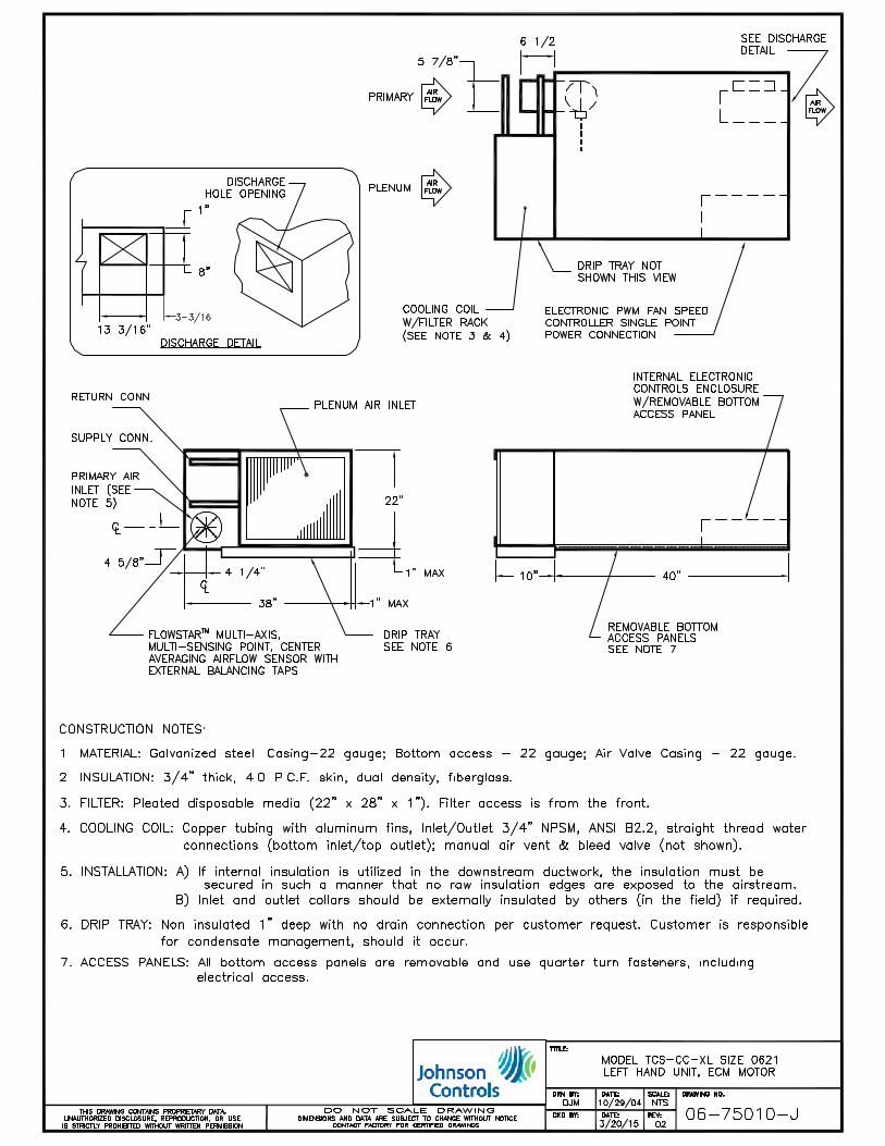
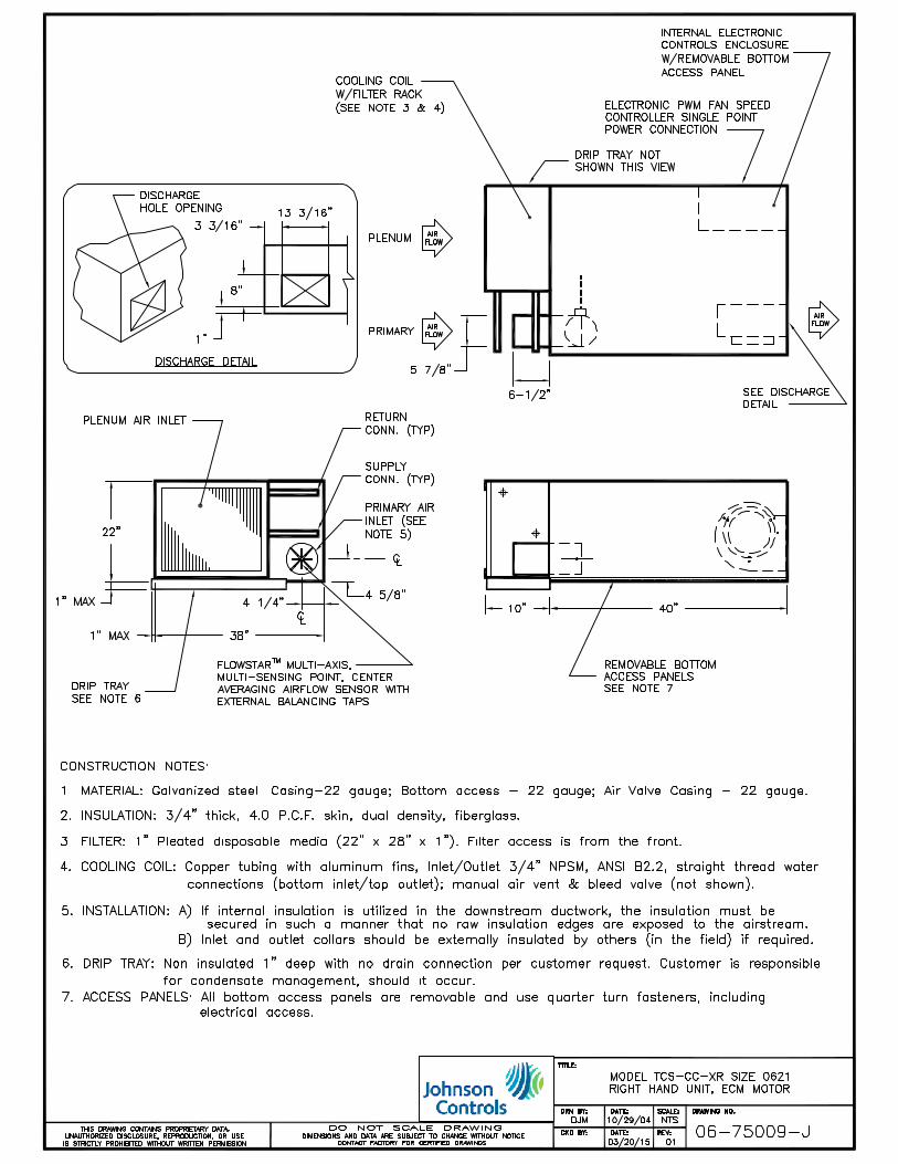
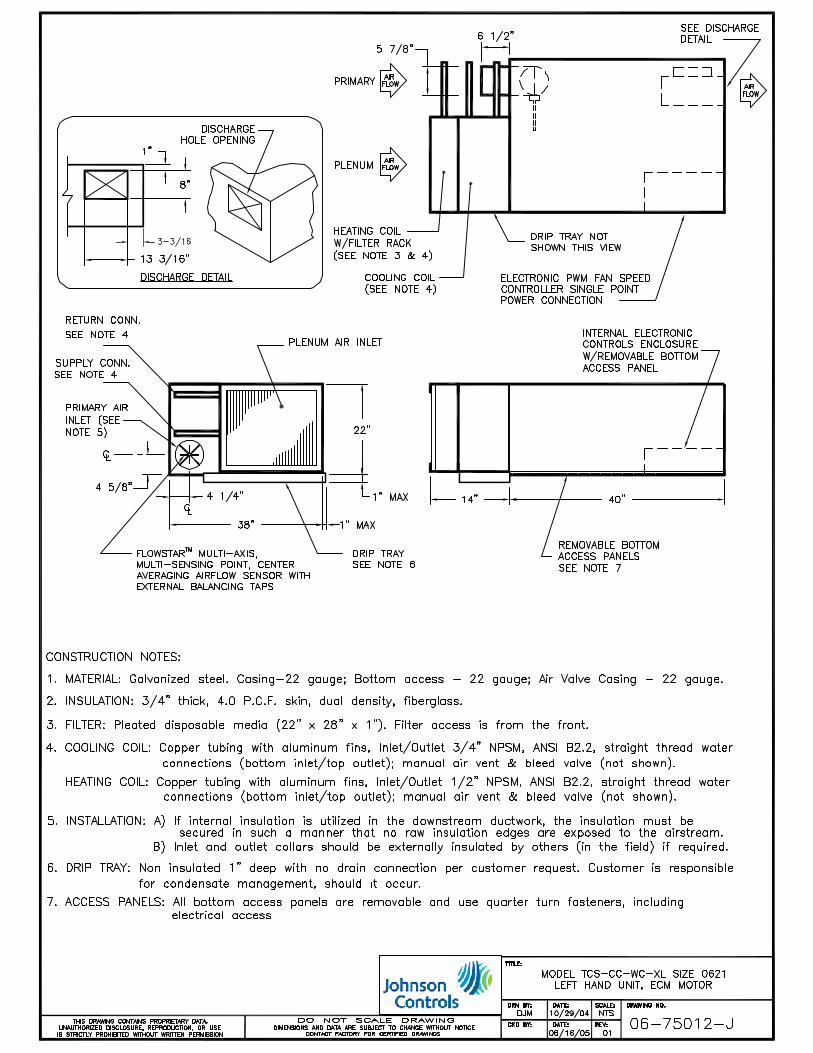
The DOAS unit provides the Designer, Owner and Occupant with a series fan powered terminal unit which includes an integral chilled water sensible only coil at the plenum air inlet. The primary air inlet is sized to provide conditioned, dehumidified air from a DOAS (dedicated outside air system) air handler, continuously measuring and controlling to minimum ventilation rates. The coil provides sensible cooling capacity and control at the zone level. Optional hot water reheat is available to meet comfort needs without additional secondary systems.
APPLICATION SPECIFIC COILS
Care must be taken when sizing DOAS terminal units and coils to ensure proper operation and reliable occupant comfort. Johnson Controls manufactures the chilled and hot water coils allowing for flexibility for job specific design requirements.
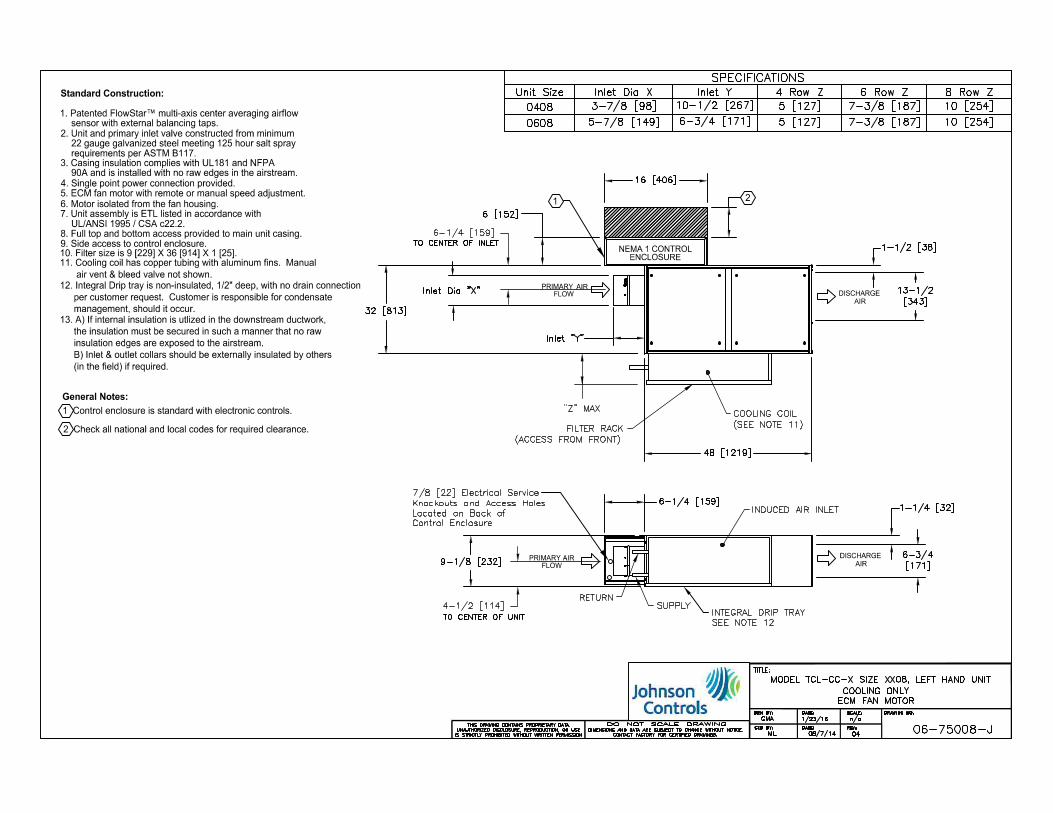
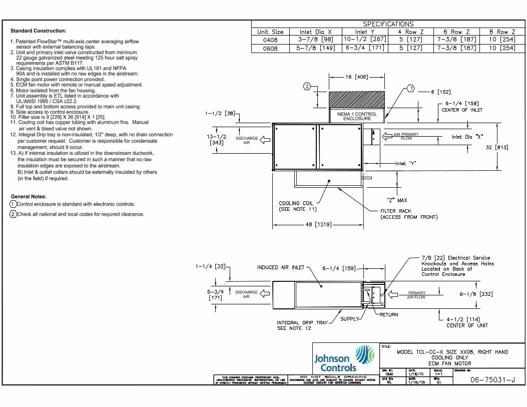
INTEGRAL DRIP TRAY
Factory installed drip tray in case sensible cooling coil temporarily experiences non-design conditions.
ENERGY EFFICIENT SOLUTIONS
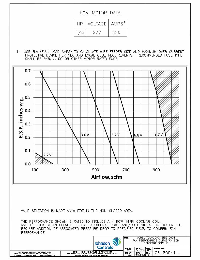
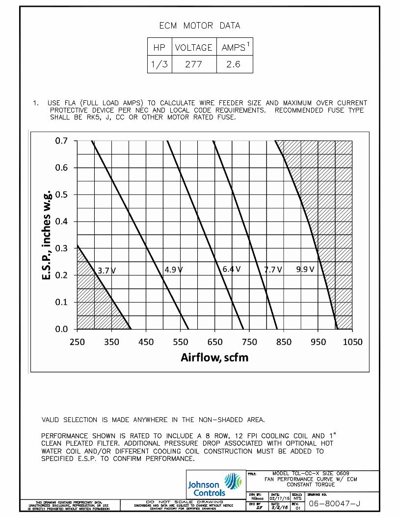
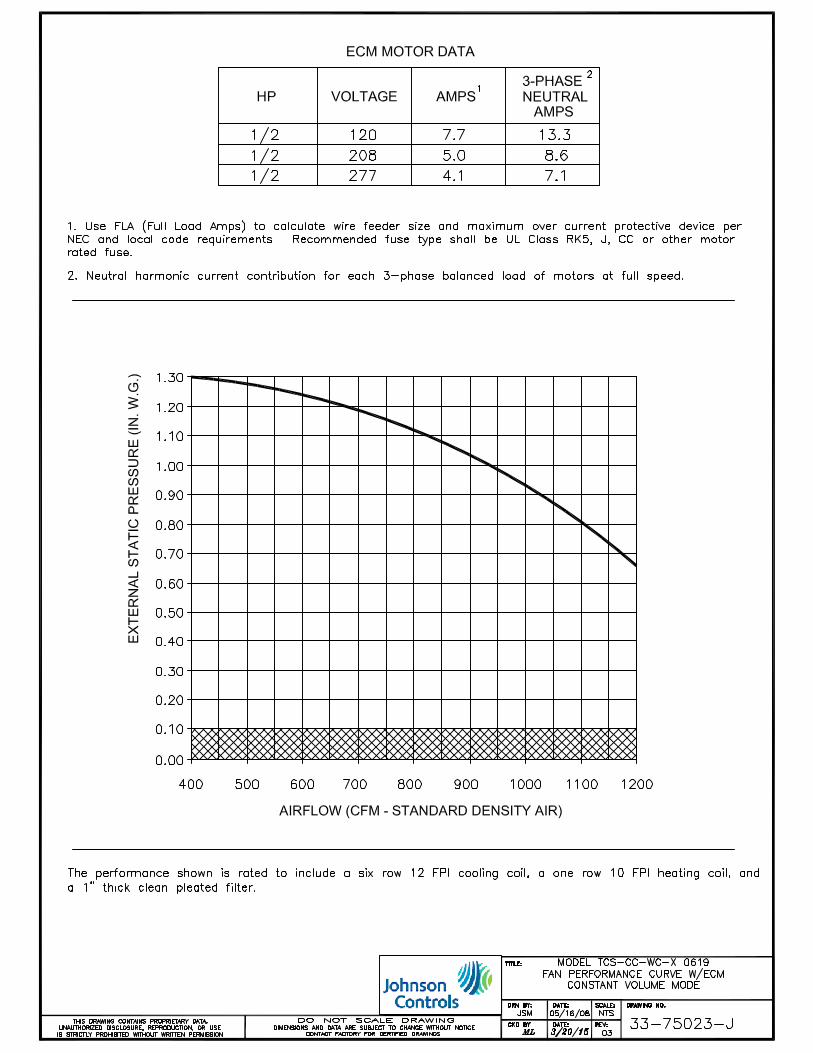
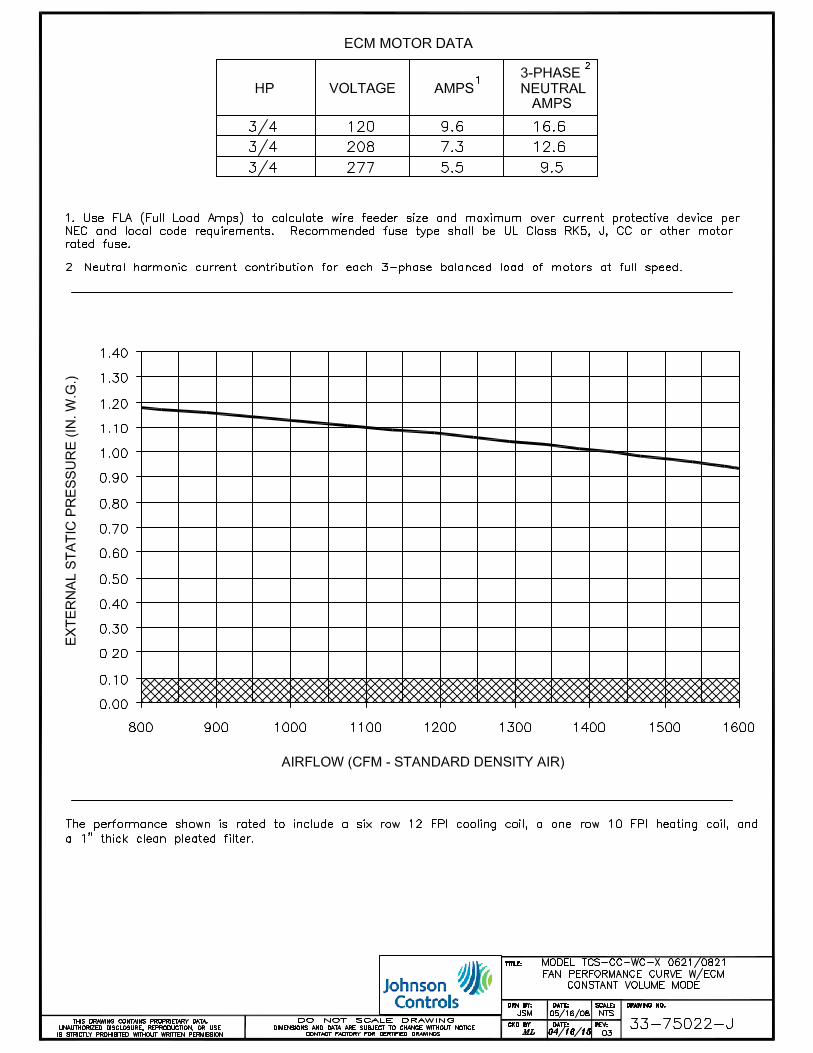
ECM motors are standard to optimize fan energy use with latest energy efficient motor technology. Available with a remote or manual speed adjustment for addressing multiple control strategies.
PATENTED FlowStar™ INLET SENSOR
The industry’s best – FlowStar™ is a multi-axis center averaging airflow sensor with external balancing taps.

FAN
CFM 125 250 500 1000 2000 4000 125 250 500 1000 2000 4000
0 0 52 52 50 43 38 31 61 56 56 52 50 44
25 100 52 52 50 44 39 32 61 56 56 52 50 44
50 200 53 53 51 46 41 34 61 56 56 53 50 45
0 0 56 55 53 47 42 34 66 61 59 57 54 49
25 150 56 56 54 48 43 36 66 61 60 58 55 51
50 300 56 57 55 49 44 38 67 62 61 59 56 53
0 0 58 58 56 50 45 37 66 61 61 59 56 52
25 200 59 59 57 51 47 40 67 63 63 62 59 57
50 400 60 60 58 53 49 43 68 65 65 65 62 60
0 0 60 60 57 55 49 42 68 65 64 65 61 58
25 250 62 62 60 55 51 44 69 65 65 65 62 59
50 500 64 64 62 56 52 46 71 66 66 66 63 61
0 0 62 64 60 57 54 46 71 68 67 69 65 62
25 300 64 65 62 58 54 47 72 68 68 69 66 63
45 550 66 67 65 59 55 49 73 69 69 69 67 65
0 0 64 65 62 58 56 50 72 70 69 71 67 65
25 350 66 66 64 59 56 50 73 70 70 71 68 66
40 550 68 68 66 60 57 51 74 71 71 72 69 68
400
600
800
1000
% CFMFull Octave Band, Hz Full Octave Band, Hz
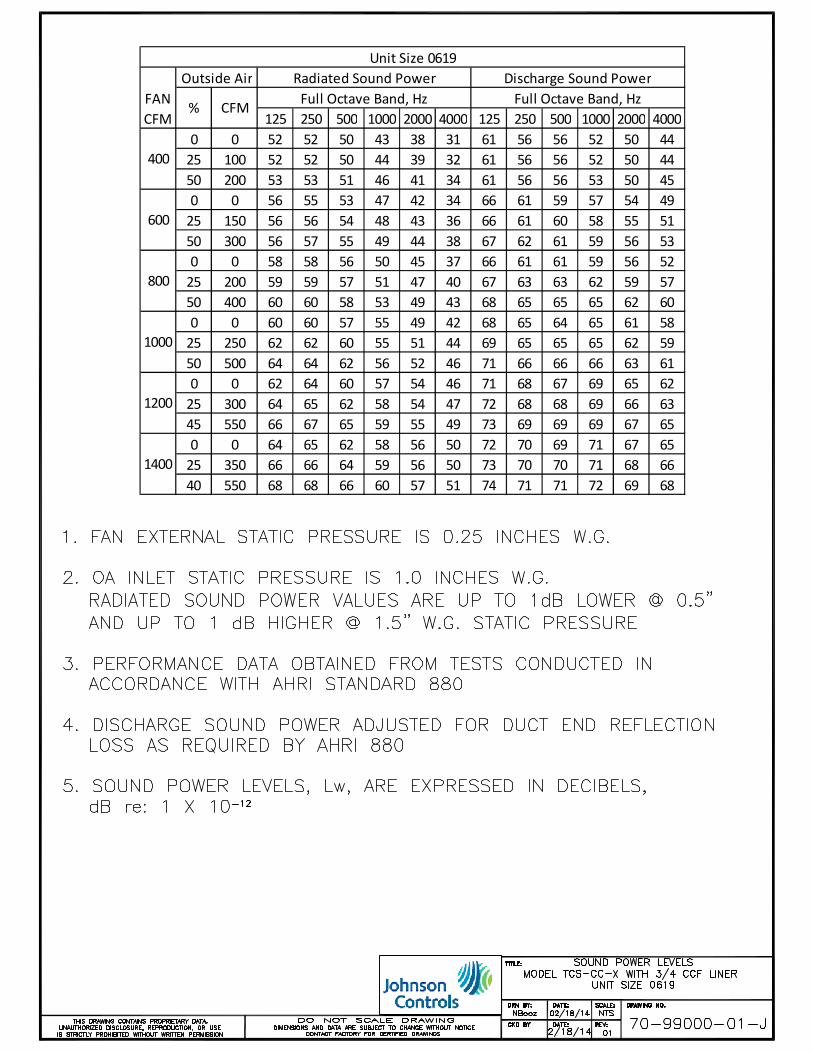
Unit Size 0619
1200
1400
Outside Air Radiated Sound Power Discharge Sound Power
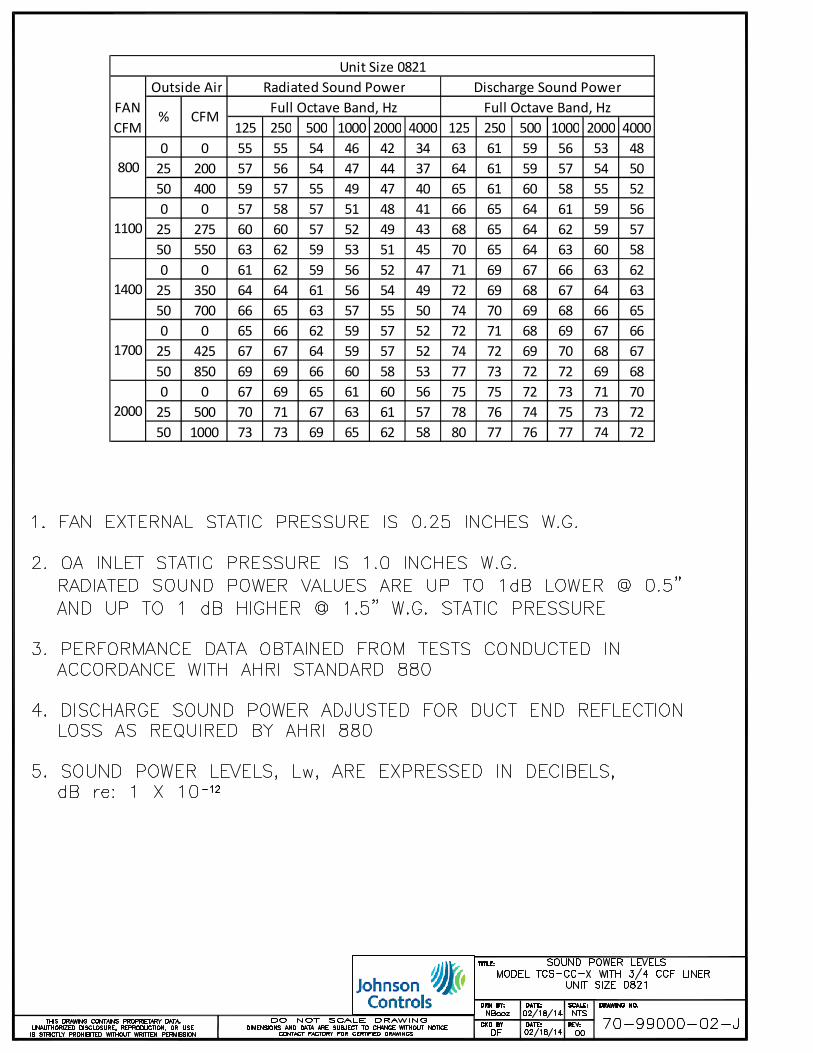
FAN
CFM 125 250 500 1000 2000 4000 125 250 500 1000 2000 4000
0 0 55 55 54 46 42 34 63 61 59 56 53 48
25 200 57 56 54 47 44 37 64 61 59 57 54 50
50 400 59 57 55 49 47 40 65 61 60 58 55 52
0 0 57 58 57 51 48 41 66 65 64 61 59 56
25 275 60 60 57 52 49 43 68 65 64 62 59 57
50 550 63 62 59 53 51 45 70 65 64 63 60 58
0 0 61 62 59 56 52 47 71 69 67 66 63 62
25 350 64 64 61 56 54 49 72 69 68 67 64 63
50 700 66 65 63 57 55 50 74 70 69 68 66 65
0 0 65 66 62 59 57 52 72 71 68 69 67 66
25 425 67 67 64 59 57 52 74 72 69 70 68 67
50 850 69 69 66 60 58 53 77 73 72 72 69 68
0 0 67 69 65 61 60 56 75 75 72 73 71 70
25 500 70 71 67 63 61 57 78 76 74 75 73 72
50 1000 73 73 69 65 62 58 80 77 76 77 74 72
1700
2000
% CFMFull Octave Band, Hz
Unit Size 0821
800
1100
1400
Full Octave Band, Hz
Outside Air Radiated Sound Power Discharge Sound Power


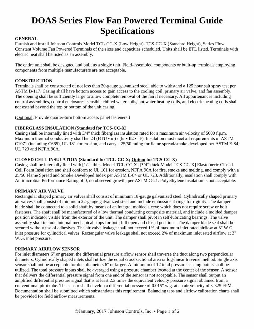
DOAS Series Flow Fan Powered Terminal Guide
Specifications
©January, 2017 Johnson Controls, Inc. • Page 1 of 2
GENERAL
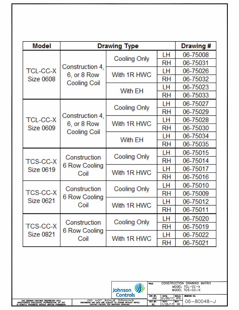
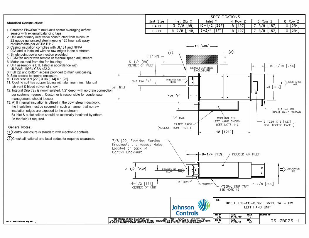
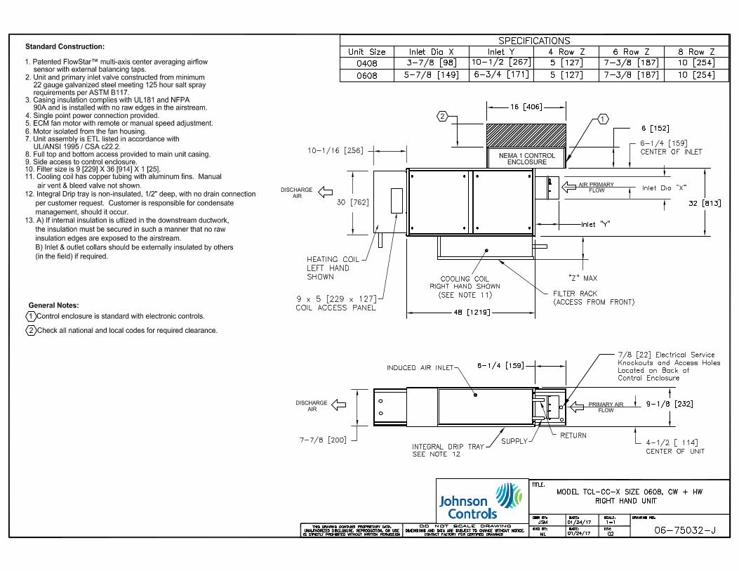
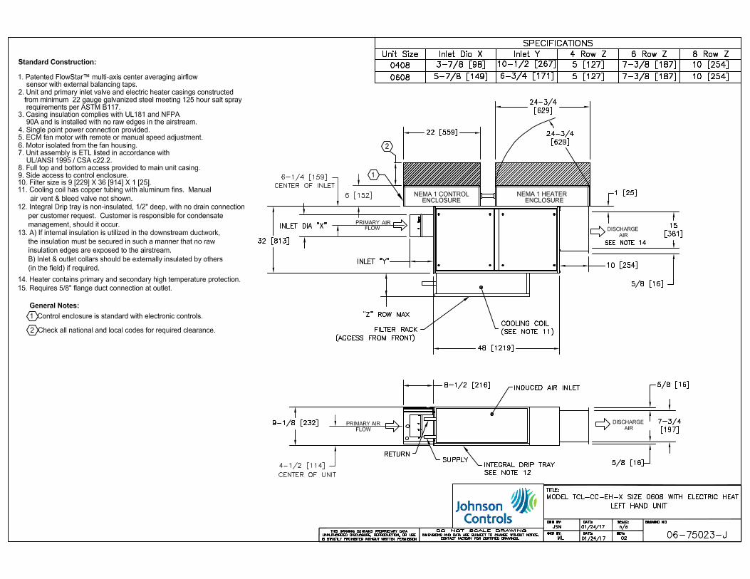
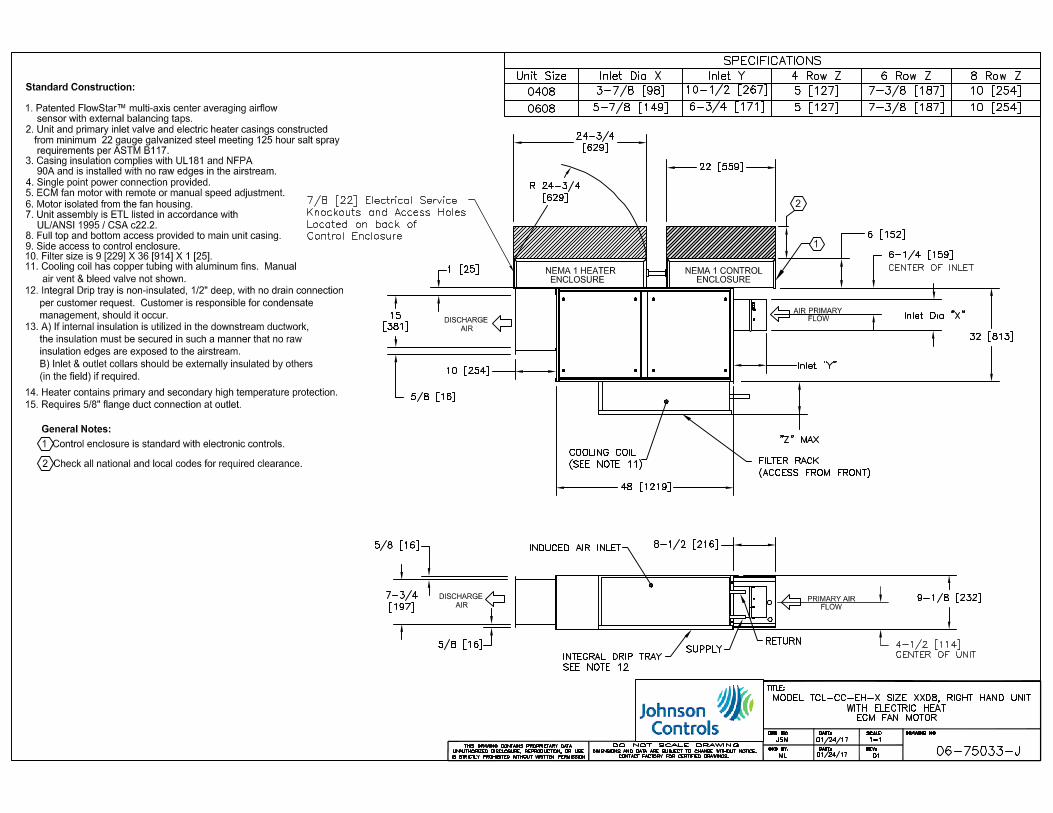
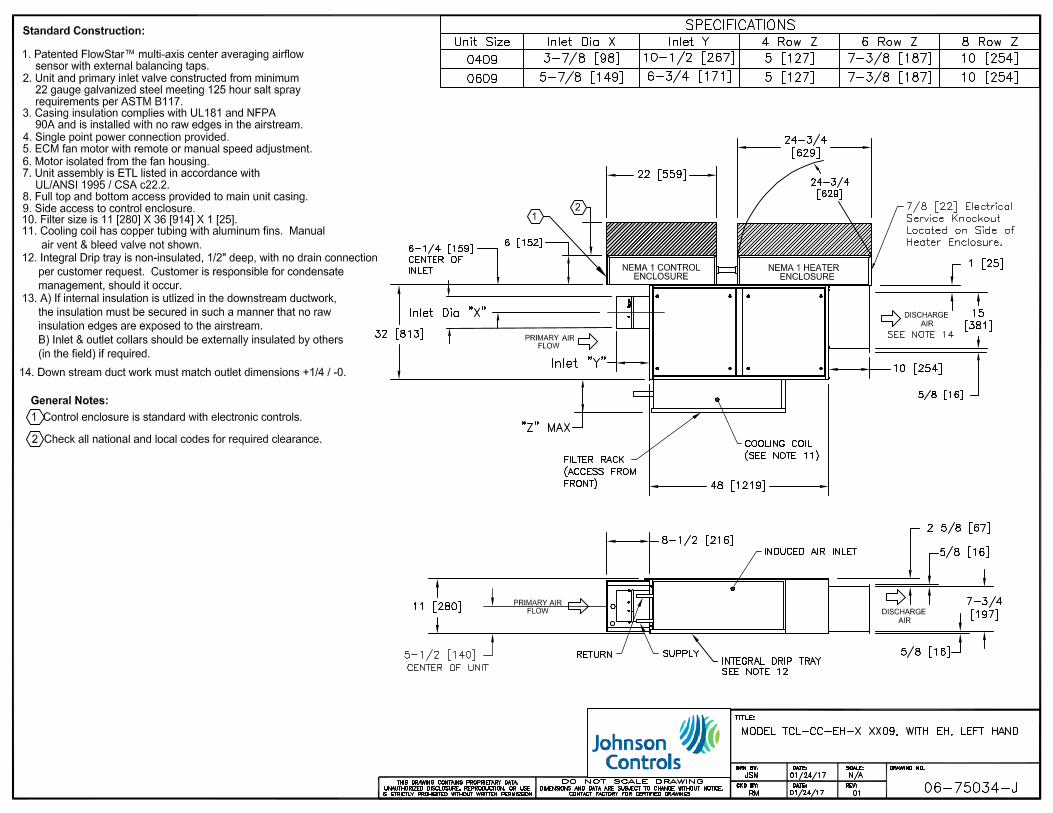
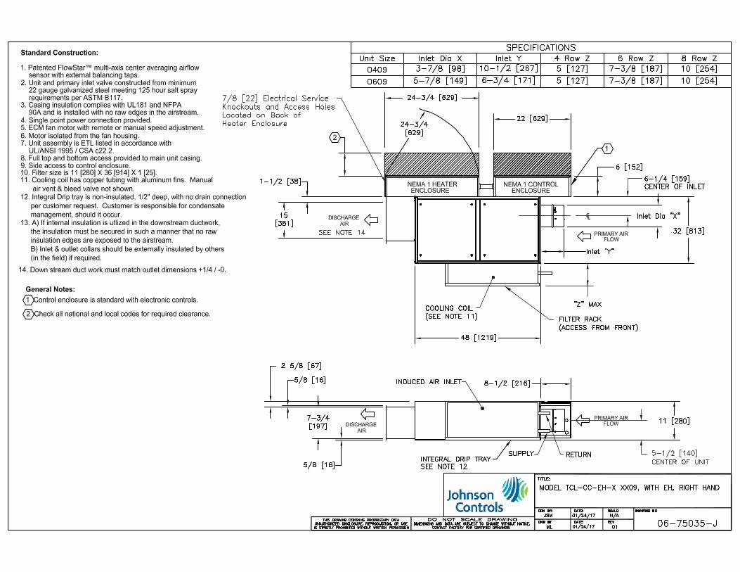
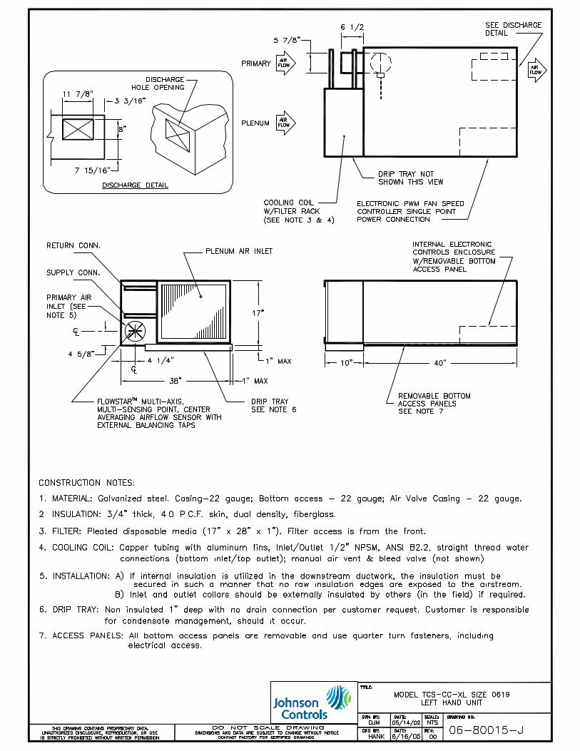
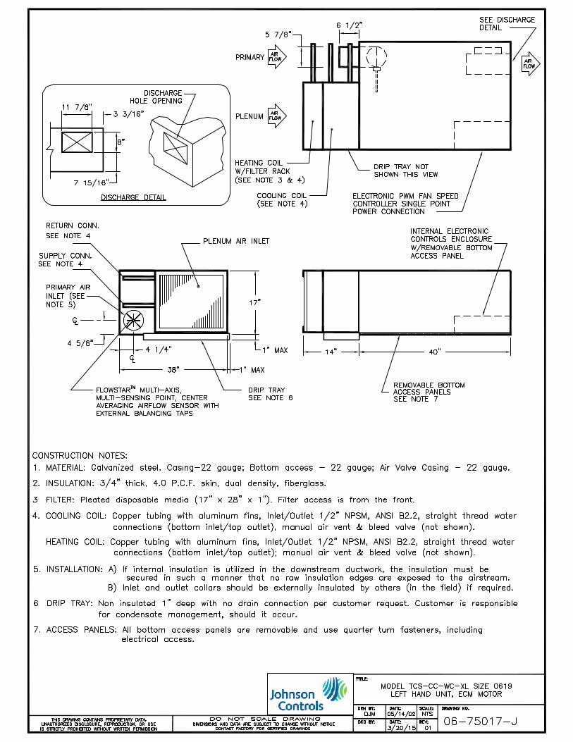
Furnish and install Johnson Controls Model TCL-CC-X (Low Height), TCS-CC-X (Standard Height), Series Flow
Constant Volume Fan Powered Terminals of the sizes and capacities scheduled. Units shall be ETL listed. Terminals with
electric heat shall be listed as an assembly.
The entire unit shall be designed and built as a single unit. Field-assembled components or built-up terminals employing
components from multiple manufacturers are not acceptable.
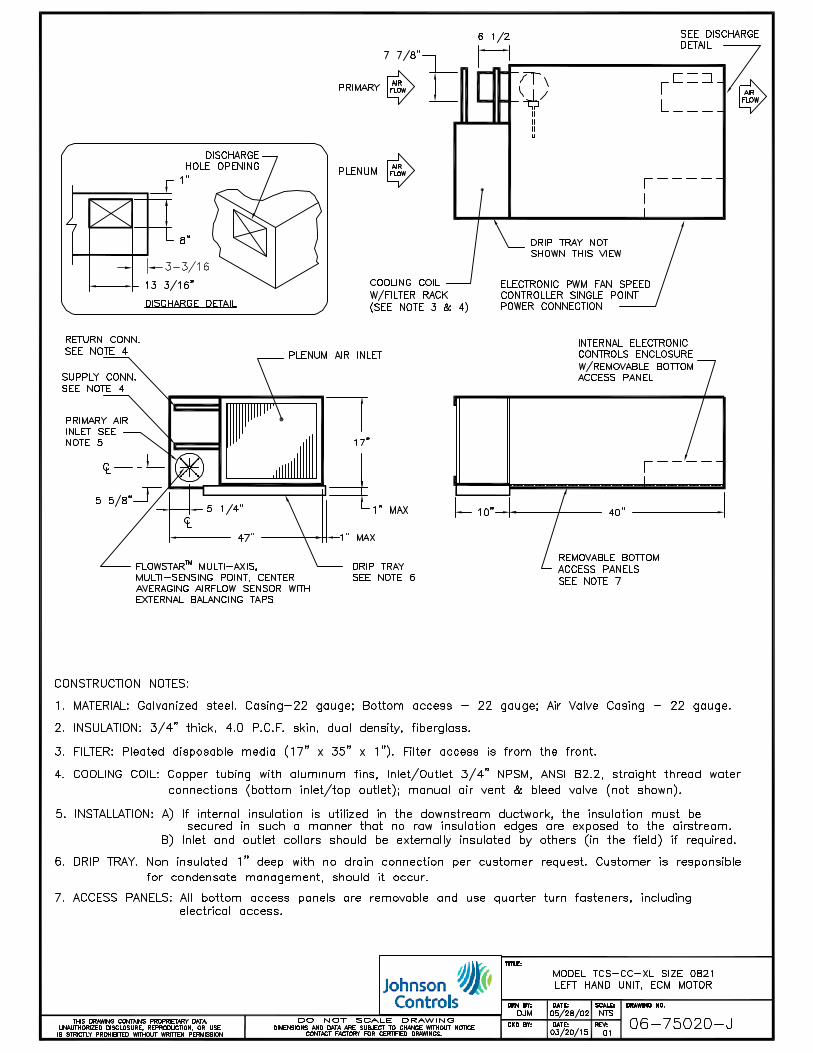
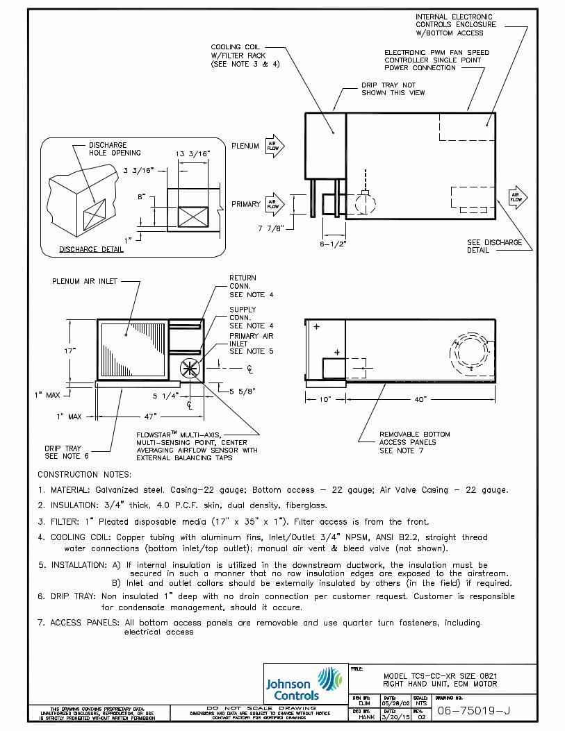
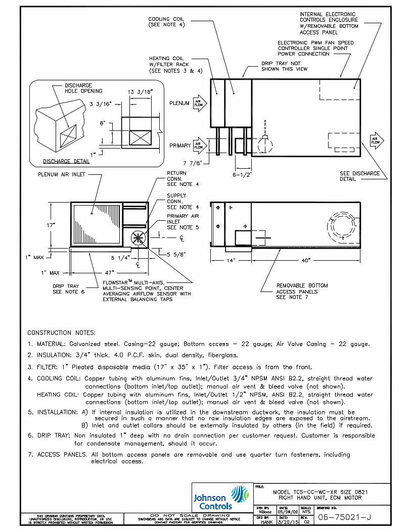
CONSTRUCTION
Terminals shall be constructed of not less than 20-gauge galvanized steel, able to withstand a 125 hour salt spray test per
ASTM B-117. Casing shall have bottom access to gain access to the cooling coil, primary air valve, and fan assembly.
The opening shall be sufficiently large to allow complete removal of the fan if necessary. All appurtenances including
control assemblies, control enclosures, sensible chilled water coils, hot water heating coils, and electric heating coils shall
not extend beyond the top or bottom of the unit casing.
(Optional: Provide quarter-turn bottom access panel fasteners.)
FIBERGLASS INSULATION (Standard for TCS-CC-X)
Casing shall be internally lined with 3/4" thick fiberglass insulation rated for a maximum air velocity of 5000 f.p.m.
Maximum thermal conductivity shall be .24 (BTU • in) / (hr • ft2 • °F). Insulation must meet all requirements of ASTM
C1071 (including C665), UL 181 for erosion, and carry a 25/50 rating for flame spread/smoke developed per ASTM E-84,
UL 723 and NFPA 90A.
CLOSED CELL INSULATION (Standard for TCL-CC-X; Option for TCS-CC-X)
Casing shall be internally lined with [1/2" thick Model TCL-CC-X] [3/4” thick Model TCS-CC-X] Elastomeric Closed
Cell Foam Insulation and shall conform to UL 181 for erosion, NFPA 90A for fire, smoke and melting, and comply with a
25/50 Flame Spread and Smoke Developed Index per ASTM E-84 or UL 723. Additionally, insulation shall comply with
Antimicrobial Performance Rating of 0, no observed growth, per ASTM G-21. Polyethylene insulation is not acceptable.
PRIMARY AIR VALVE
Rectangular shaped primary air valves shall consist of minimum 18-gauge galvanized steel. Cylindrically shaped primary
air valves shall consist of minimum 22-gauge galvanized steel and include embossment rings for rigidity. The damper
blade shall be connected to a solid shaft by means of an integral molded sleeve which does not require screw or bolt
fasteners. The shaft shall be manufactured of a low thermal conducting composite material, and include a molded damper
position indicator visible from the exterior of the unit. The damper shall pivot in self-lubricating bearings. The valve
assembly shall include internal mechanical stops for both full open and closed positions. The damper blade seal shall be
secured without use of adhesives. The air valve leakage shall not exceed 1% of maximum inlet rated airflow at 3" W.G.
inlet pressure for cylindrical valves. Rectangular valve leakage shall not exceed 2% of maximum inlet rated airflow at 3"
W.G. inlet pressure.
PRIMARY AIRFLOW SENSOR
For inlet diameters 6" or greater, the differential pressure airflow sensor shall traverse the duct along two perpendicular
diameters. Cylindrically shaped inlets shall utilize the equal cross sectional area or log-linear traverse method. Single axis
sensor shall not be acceptable for duct diameters 6" or larger. A minimum of 12 total pressure sensing points shall be
utilized. The total pressure inputs shall be averaged using a pressure chamber located at the center of the sensor. A sensor
that delivers the differential pressure signal from one end of the sensor is not acceptable. The sensor shall output an
amplified differential pressure signal that is at least 2.3 times the equivalent velocity pressure signal obtained from a
conventional pitot tube. The sensor shall develop a differential pressure of 0.015" w.g. at an air velocity of < 325 FPM.
Documentation shall be submitted which substantiates this requirement. Balancing taps and airflow calibration charts shall
be provided for field airflow measurements.
DOAS Series Flow Fan Powered Terminal Guide
Specifications
©January, 2017 Johnson Controls, Inc. • Page 2 of 2
FAN ASSEMBLY
The unit fan shall utilize a forward curved, dynamically balanced, galvanized wheel with a direct drive motor. The fan
motor shall be un-pluggable from the electrical leads at the motor case for simplified removal. The motor shall be
mounted to the fan housing using rubber grommets to minimize vibration transfer.
Fan motor shall be ECM™. Motor shall be brushless DC controlled by an integral controller / inverter that operates the
wound stator and senses rotor position to electronically commutate the stator. Motor shall be permanent magnet type with
near-zero rotor losses designed for synchronous rotation. The motor shall utilize permanently lubricated ball bearings.
Motor shall maintain minimum 70% efficiency over the entire operating range. Motor speed control shall be accomplished
through a PWM (pulse width modulation) controller specifically designed for compatibility with the ECM™. The speed
controller shall have terminals for field verification of fan capacity utilizing a digital volt meter. A calibration graph shall
be supplied indicating Fan CFM verses DC Volts.
CHILLED WATER SENSIBLE COOLING COIL & DRIP TRAY
Terminal shall include an integral chilled water sensible cooling coil. The coil shall be manufactured by the terminal unit
manufacturer and shall have a minimum 22-gauge galvanized sheet metal casing. Coil shall be constructed of aluminum
fins with full fin collars mechanically fixed to copper tubes to assure accurate fin spacing and maximum heat transfer. A
galvanized steel drip tray shall be provided, factory installed underneath the sensible cooling coil. Each coil shall be
hydrostatically tested at 450 PSIG, and rated for a maximum 300 PSIG working pressure at 200°F.
HOT WATER COIL
Terminal shall include an integral hot water coil where indicated on the plans. The coil shall be manufactured by the
terminal unit manufacturer and shall have a minimum 22-gauge galvanized sheet metal casing. Coil shall be constructed
of aluminum fins with full fin collars mechanically fixed to copper tubes to assure accurate fin spacing and maximum heat
transfer. Each coil shall be hydrostatically tested at 450 PSIG, and rated for a maximum 300 PSIG working pressure at
200°F. Coils shall incorporate a built in, flush mounted access plate, allowing bottom access to coil.
ELECTRIC HEAT (TCL Only)
Terminal shall include an integral electric heater where indicated on the plans. Heater shall be manufactured by the
terminal unit manufacturer. The heater cabinet shall be constructed of not less than 20-gauge galvanized steel. Heater shall
have a hinged access panel for entry to the controls.
Heater shall be furnished with all controls necessary for safe operation and full compliance with UL 1995 and National
Electric Code requirements. Heater shall have a single point electrical connection (optional: door interlocking fused
disconnect switch). It shall include magnetic contactors (optional: staged solid state relays), (optional: airflow switch),
primary disc-type automatic reset high temperature limit, secondary high limit(s), Ni-Chrome elements and fusing per UL
and NEC. Heater shall have complete wiring diagram with label indicating power requirement and kW output. Heater
shall be interlocked with fan terminal so as to preclude operation of the heater when the fan is not running.
ELECTRICAL
Terminals shall have a single point power connection. (Optional: toggle disconnect and motor fusing for units without
electric heat).
FILTERS
Terminals shall include a filter rack and 1" thick disposable fiberglass filter (optional: MERV 8 filter).
CONTROLS COORDINATION
Furnish a NEMA 1 control enclosure with 24-volt transformer and factory mount and wire DDC controller and primary
air damper actuator provided by automatic temperature control contractor. [Model TCS-CC-X, primary air actuator must
be separate component and NOT integral to the controller.]


Catalog: 130.13-EG8 (317) Supersedes: Nothing © 2017 Johnson Controls www.johnsoncontrols.com