Embed Size (px)
Citation preview
PARALLEL FAN POWERED TERMINAL UNITSMETALAIRE’s parallel fan-powered terminal units are designed to provide superior comfort by intermittent parallel fan operation. Conditioned primary air is varied during cooling while the fan cycles on during heating. Parallel fan-powered terminal units allow for recovery of waste heat from the return plenum and a potential reduction in central fan energy, thereby lowering operating costs. In the heating mode with the fan energized, parallel fan-powered terminal units improve air circulation through better diffuser performance.
The primary function of the METALAIRE parallel fan-powered terminal unit is to deliver variable volume, constant temperature primary air to the space in the cooling mode. The volume of supply air is varied in response to a control signal. In the heating mode, with the fan energized, the terminal unit mixes conditioned air and plenum air in response to a control signal to supply constant volume, variable temperature supply air into the space. Supplemental heating is available in both electric heat and hot water coils if plenum heat is insufficient. METALAIRE parallel fan-powered terminal units are available with a wide range of control options to suit any application. These include pneumatic, analog electronic, electric, and direct digital control (DDC). With the demands of today’s building designs to reduce energy in smaller mechanical spaces, the METALAIRE parallel fan-powered terminal unit is the perfect choice.
FEATURES■ FVI-500 is available in 7 casing sizes to handle 150 – 5600 CFM.■ FVL-600 is available in 2 casing sizes to handle 150 – 1825 CFM.■ 22 ga. galvanized steel casing, mechanically sealed,
low leakage construction.■ Mechanically fastened damper assembly is double layer, 18
gauge equivalent, galvanized steel with integral blade seal. (<1% at 3" static pressure).
■ Factory calibrated controls per each job requirement.■ METALAIRE multi-quadrant averaging flow sensor provides highly
accurate +/- 5% flow readings after certified balancer has bal-anced terminal.
■ Easy access, steel balancing taps.■ Energy efficient PSC motors with adjustable SCR solid state fan
speed controllers are standard.■ Electronically Commutated Motors (ECM) available as an option.■ External control cabinet with offset mounting plate as standard.
■ Single point electrical connections.■ 3-beaded primary inlet connection tube for added rigidity and
secure flex duct connections.■ Round inlets available in sizes 6" through 16".■ 1" thick, dual density (1.5lb / ft3 min.) fiberglass insulation with
edges coated. Meets NFPA 90A and UL 181 (1/2" thick insulation standard on FVL-600).
■ Rectangular discharge with optional slip and drive duct connection.
■ Large removable bottom access panel provides complete access to interior of unit.
■ Independently tested and certified laboratory performance data.■ Full range of options and accessories available (heating coils,
disconnects, attenuators, etc.).■ Full range of liners / insulation available.
FVI-500 FVL-600 VARIABLE VOLUME UNIT LOW-PROFILE VARIABLE VOLUME UNIT
Metal Industries, Inc. ■ For complete product specifications and submittal data, visit us at www.metalaire.com
PA
RA
LLEL
FAN
PO
WER
ED
TER
MIN
AL
UN
ITS
FP–90
FP–91© 2015 Metal Industries, Inc.
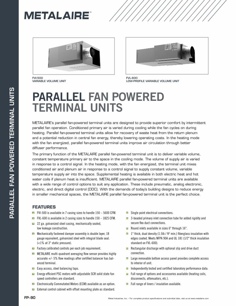
FVI-500 VARIABLE VOLUME FAN TERMINAL UNIT
SPECIFIABLE FEATURES
■ Galvanized steel casing, mechanically sealed for low leakage construction■ NEMA TYPE 1 rated hinged control enclosure with standoff to prevent penetration of casing■ Single speed high efficiency PSC motor with SCR motor speed control■ Continuous welded primary inlet duct to minimize leakage with 3 stiffening beads for added rigidity■ Damper construction of double layer 18 gauge equivalent with integral blade seal■ All metal constructed inlet flow sensor with extra balancing taps■ Single point electrical connection■ Gasketed back draft damper door to minimize leakage in cooling mode
INDEX OF SECTIONS PAGE
Dimensional Data 94
AHRI Data / Certification and Standards 102
Acoustic Performance 103
Motor Data / Damper Leakage 117
Minimum Pressures Chart 118
Coil Selection 119
Accessories and Components – Shipping Weights / Induction Filter Sizes 123
Available Controls 128
Fan Performance Curves 129
FVI-5
00
VA
RIA
BLE
VO
LUM
EPA
RA
LLEL FA
N P
OW
ERED
FP–92 Metal Industries, Inc. ■ For complete product specifications and submittal data, visit us at www.metalaire.com
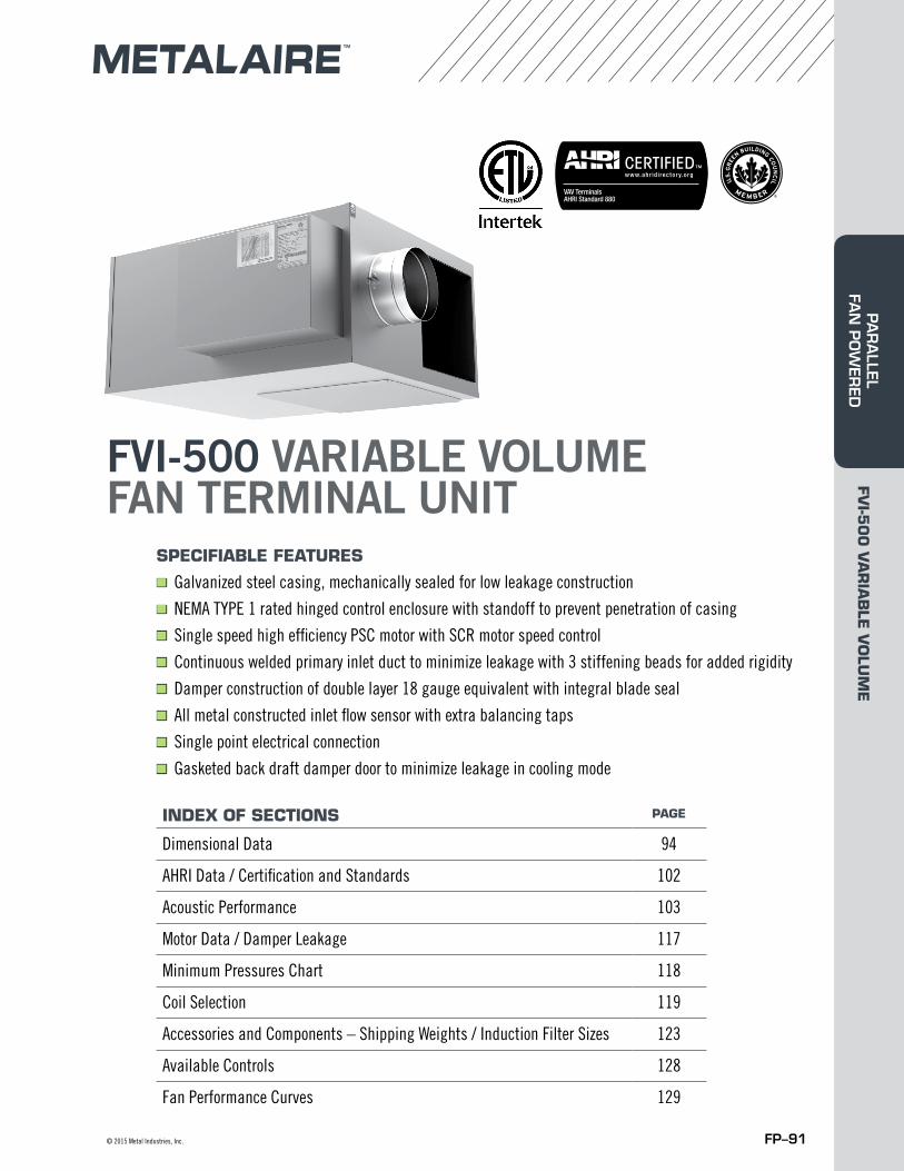
FVI-500 VARIABLE VOLUME FAN TERMINAL UNITMETALAIRE’s model FVI-500 parallel fan-powered terminal unit is designed to provide superior comfort to zones by intermittent parallel fan operation. Conditioned primary air is varied during cooling while the fan cycles on during heating. Parallel fan-powered terminal units allow for recovery of waste heat from the return plenum and a potential reduction in central fan energy, thereby lowering operating costs. In the heating mode with the fan energized, parallel fan-powered terminal units improve air circulation through better diffuser performance. The primary air does not pass through the fan.
The primary function of the METALAIRE model FVI-500 parallel fan-powered terminal unit is to deliver variable volume, constant temperature primary air to the space in the cooling mode. The volume of supply air is varied in response to a control signal. In the heating mode, with the fan energized, the terminal unit mixes conditioned air and plenum air in response to a control signal to supply constant volume, variable temperature supply air into the space. Supplemental heating is available in both electric heat and hot water coils if plenum heat is insufficient. METALAIRE model FVI-500 parallel fan-powered terminal units are available with a wide range of control options to suit any application. These include pneumatic, analog electronic, electric, factory provided commissioned direct digital control (DDC) or factory mounted field supplied (DDC) controls. With the demands of today’s building designs to reduce energy in smaller mechanical spaces, the METALAIRE model FVI-500 parallel fan-powered terminal unit is the perfect choice.
STANDARD FEATURES■ Available in 7 casing sizes to handle 150–5600 CFM.■ 22 ga. galvanized steel casing, mechanically sealed,
low leakage construction.■ Mechanically fastened damper assembly is double layer, 18 gauge
equivalent, galvanized steel with integral blade seal. (<1% at 3” static pressure).
■ Factory calibrated controls per each job requirement. ■ METALAIRE multi-quadrant averaging flow sensor provides highly
accurate +/- 5% flow readings after certified balancer has bal-anced terminal.
■ Easy access, steel balancing taps. ■ Energy efficient six pole single speed PSC motors with adjustable
SCR solid state fan speed controllers are standard. ■ Electronically Commutated Motors (ECM) available as an option.■ Available fan motor voltages of 120,277 and 208-240 (50 / 60 HZ)■ External control cabinet with offset mounting plate as standard.
■ Single point electrical connections.■ 3-beaded primary inlet connection tube for added rigidity and
secure flex duct connections.■ Round inlets available in sizes 6" through 16".■ 1" thick, dual density (1.5lb / ft3 min.) fiberglass insulation
with edges coated. Meets NFPA 90A and UL 181. (1/2" thick insulation standard on FVL-600).
■ Rectangular flanged discharge with optional slip and drive cleat duct connection.
■ Large Bottom access panel provides access to fan motor / blower assembly.
■ Independently tested and certified laboratory performance data.■ Full range of options and accessories available (heating coils,
disconnects, attenuators, etc.).■ Full range of liners / insulation available. ■ Auto and manual thermal resets on every electric heater.
FVI-5
00
VA
RIA
BLE
VO
LUM
EPA
RA
LLEL
FA
N P
OW
ERED
FP–93© 2015 Metal Industries, Inc.
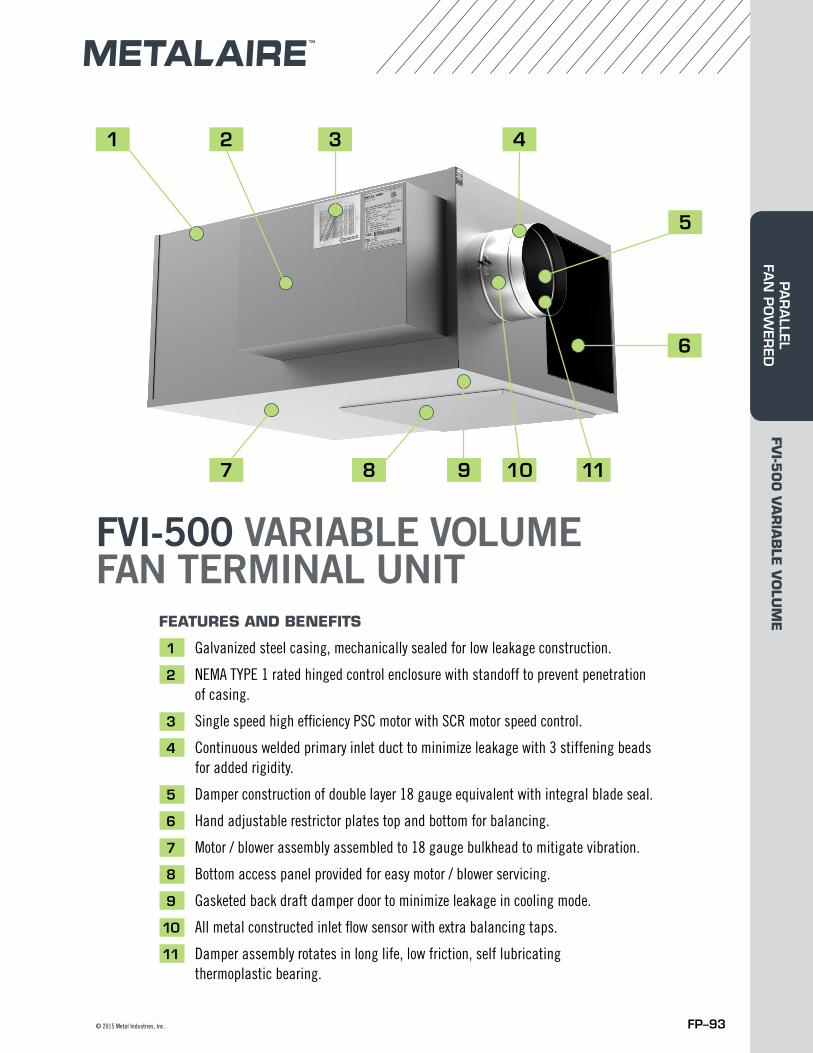
FVI-500 VARIABLE VOLUME FAN TERMINAL UNIT
FEATURES AND BENEFITS
1 Galvanized steel casing, mechanically sealed for low leakage construction.
2 NEMA TYPE 1 rated hinged control enclosure with standoff to prevent penetration of casing.
3 Single speed high efficiency PSC motor with SCR motor speed control.
4 Continuous welded primary inlet duct to minimize leakage with 3 stiffening beads for added rigidity.
5 Damper construction of double layer 18 gauge equivalent with integral blade seal.
6 Hand adjustable restrictor plates top and bottom for balancing.
7 Motor / blower assembly assembled to 18 gauge bulkhead to mitigate vibration.
8 Bottom access panel provided for easy motor / blower servicing.
9 Gasketed back draft damper door to minimize leakage in cooling mode.
10 All metal constructed inlet flow sensor with extra balancing taps.
11 Damper assembly rotates in long life, low friction, self lubricating thermoplastic bearing.
11
1 2 3 4
5
6
9 1087
FVI-5
00
VA
RIA
BLE
VO
LUM
EPA
RA
LLEL FA
N P
OW
ERED
FP–94 Metal Industries, Inc. ■ For complete product specifications and submittal data, visit us at www.metalaire.com
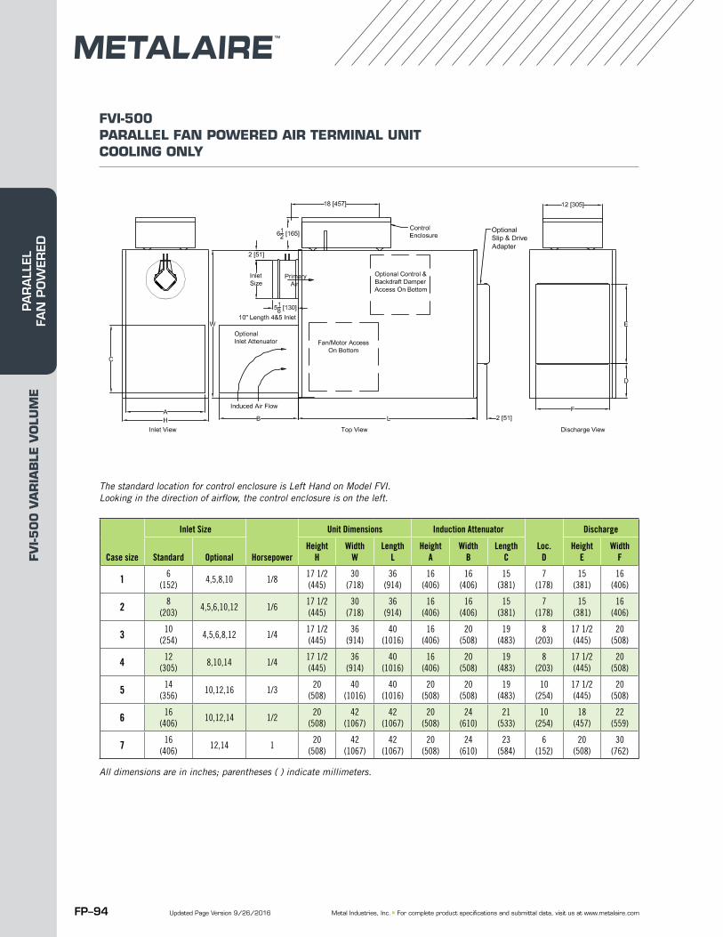
Case Inlet Size Horse Unit Unit Unit Optional Induction Attenuator DischargeSize Standard Optional Power Height Width Length Height Width Length Loc. Height Width
H W L A B C D E F1 6 (152) 4, 5, 8,10 1/8 17 1/2 (445) 30 (718) 36 (914) 16 (406) 16 (406) 15 (381) 7 (178) 15 (381) 16 (406)2 8 (203) 4,5,6,10,12 1/6 17 1/2 (445) 30 (718) 36 (914) 16 (406) 16 (406) 15 (381) 7 (178) 15 (381) 16 (406)3 10 (254) 4,5,6,8,12 1/4 17 1/2 (445) 36 (914) 40 (1016) 16 (406) 20 (508) 19 (483) 8 (203) 17 1/2 (445) 20 (508)4 12 (305) 8,10,14 1/4 17 1/2 (445) 36 (914) 40 (1016) 16 (406) 20 (508) 19 (483) 8 (203) 17 1/2 (445) 20 (508)5 14 (356) 10,12,16 1/3 20 (508) 40 (1016) 40 (1016) 20 (508) 20 (508) 19 (483) 10 (254) 17 1/2 (445) 20 (508)6 16 (406) 10,12,14 1/2 20 (508) 42 (1067) 42 (1067) 20 (508) 24 (610) 21 (533) 10 (254) 18 (457) 22 (559)7 16 (406) 12,14 1 20 (508) 42 (1067) 42 (1067) 20 (508) 24 (610) 23 (584) 6 (152) 20 (508) 30 (762)Case size
Inlet Size
Horsepower
Unit Dimensions Induction Attenuator
Loc.D
Discharge
Standard OptionalHeight
HWidth
WLength
LHeight
AWidth
BLength
CHeight
EWidth
F
1 6 (152)
4,5,8,10 1/817 1/2 (445)
30 (718)
36 (914)
16 (406)
16 (406)
15 (381)
7 (178)
15 (381)
16 (406)
2 8 (203)
4,5,6,10,12 1/617 1/2 (445)
30 (718)
36 (914)
16 (406)
16 (406)
15 (381)
7 (178)
15 (381)
16 (406)
3 10 (254)
4,5,6,8,12 1/417 1/2 (445)
36 (914)
40 (1016)
16 (406)
20 (508)
19 (483)
8 (203)
17 1/2 (445)
20 (508)
4 12 (305)
8,10,14 1/417 1/2 (445)
36 (914)
40 (1016)
16 (406)
20 (508)
19 (483)
8 (203)
17 1/2 (445)
20 (508)
5 14 (356)
10,12,16 1/320
(508)40
(1016)40
(1016)20
(508)20
(508)19
(483)10
(254)17 1/2 (445)
20 (508)
6 16 (406)
10,12,14 1/220
(508)42
(1067)42
(1067)20
(508)24
(610)21
(533)10
(254)18
(457)22
(559)
7 16 (406)
12,14 120
(508)42
(1067)42
(1067)20
(508)24
(610)23
(584)6
(152)20
(508)30
(762)
FVI-500 PARALLEL FAN POWERED AIR TERMINAL UNIT COOLING ONLY
The standard location for control enclosure is Left Hand on Model FVI. Looking in the direction of airflow, the control enclosure is on the left.
All dimensions are in inches; parentheses ( ) indicate millimeters.
Updated Page Version 9/26/2016
FVI-5
00
VA
RIA
BLE
VO
LUM
EPA
RA
LLEL
FA
N P
OW
ERED
FP–95© 2015 Metal Industries, Inc.
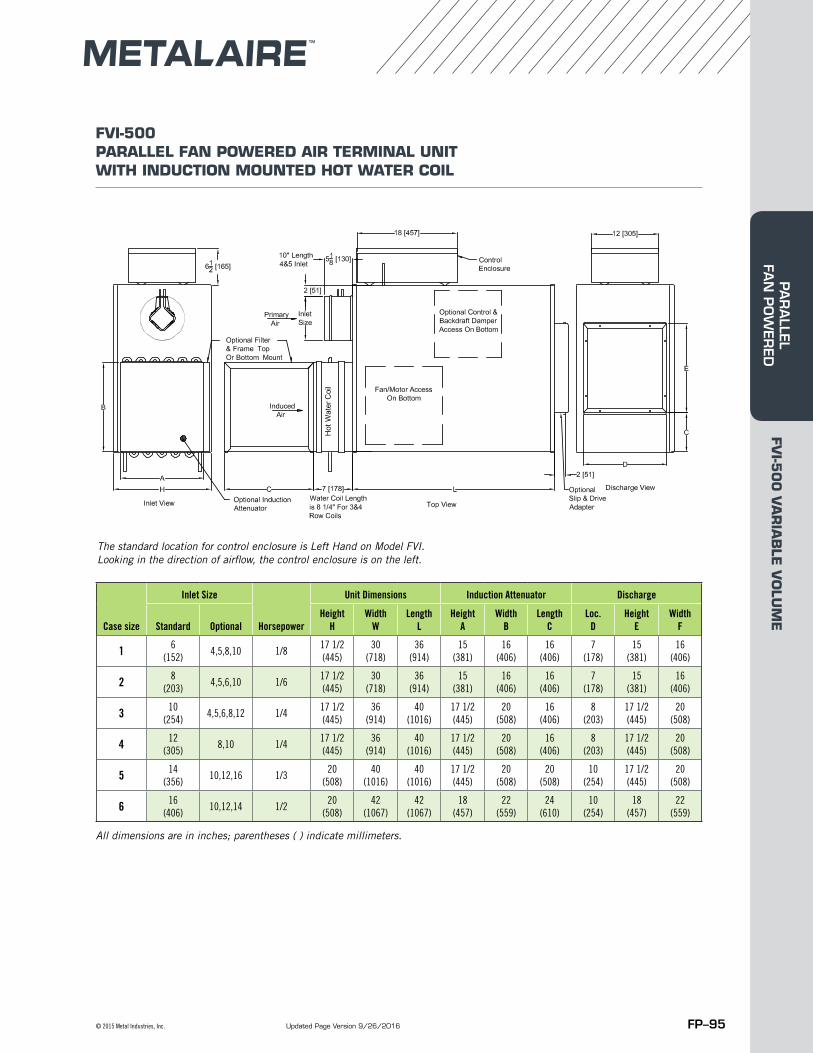
Case Inlet Size Horse Unit Unit Unit Optional Induction Attenuator DischargeSize Standard Optional Power Height Width Length Height Width Length Loc. Height Width
H W L A B C D E F1 6 (152) 4, 5, 8,10 1/8 17 1/2 (445) 30 (718) 36 (914) 15 (381) 16 (406) 16 (406) 7 (178) 15 (381) 16 (406)2 8 (203) 4,5,6,10 1/6 17 1/2 (445) 30 (718) 36 (914) 15 (381) 16 (406) 16 (406) 7 (178) 15 (381) 16 (406)3 10 (254) 4,5,6,8,12 1/4 17 1/2 (445) 36 (914) 40 (1016) 17 1/2 (445) 20 (508) 16 (406) 8 (203) 17 1/2 (445) 20 (508)4 12 (305) 8,10 1/4 17 1/2 (445) 36 (914) 40 (1016) 17 1/2 (445) 20 (508) 16 (406) 8 (203) 17 1/2 (445) 20 (508)5 14 (356) 10,12,16 1/3 20 (508) 40 (1016) 40 (1016) 17 1/2 (445) 20 (508) 20 (508) 10 (254) 17 1/2 (445) 20 (508)6 16 (406) 10,12,14 1/2) 20 (508) 42 (1067) 42 (1067) 18 (457) 22 (559) 24 (610) 10 (254) 18 (457) 22 (559)
Case size
Inlet Size
Horsepower
Unit Dimensions Induction Attenuator Discharge
Standard OptionalHeight
HWidth
WLength
LHeight
AWidth
BLength
CLoc.
DHeight
EWidth
F
1 6 (152)
4,5,8,10 1/817 1/2 (445)
30 (718)
36 (914)
15 (381)
16 (406)
16 (406)
7 (178)
15 (381)
16 (406)
2 8 (203)
4,5,6,10 1/617 1/2 (445)
30 (718)
36 (914)
15 (381)
16 (406)
16 (406)
7 (178)
15 (381)
16 (406)
3 10 (254)
4,5,6,8,12 1/417 1/2 (445)
36 (914)
40 (1016)
17 1/2 (445)
20 (508)
16 (406)
8 (203)
17 1/2 (445)
20 (508)
4 12 (305)
8,10 1/417 1/2 (445)
36 (914)
40 (1016)
17 1/2 (445)
20 (508)
16 (406)
8 (203)
17 1/2 (445)
20 (508)
5 14 (356)
10,12,16 1/320
(508)40
(1016)40
(1016)17 1/2 (445)
20 (508)
20 (508)
10 (254)
17 1/2 (445)
20 (508)
6 16 (406)
10,12,14 1/220
(508)42
(1067)42
(1067)18
(457)22
(559)24
(610)10
(254)18
(457)22
(559)
FVI-500 PARALLEL FAN POWERED AIR TERMINAL UNIT WITH INDUCTION MOUNTED HOT WATER COIL
The standard location for control enclosure is Left Hand on Model FVI. Looking in the direction of airflow, the control enclosure is on the left.
All dimensions are in inches; parentheses ( ) indicate millimeters.
Updated Page Version 9/26/2016
FVI-5
00
VA
RIA
BLE
VO
LUM
EPA
RA
LLEL FA
N P
OW
ERED
FP–96 Metal Industries, Inc. ■ For complete product specifications and submittal data, visit us at www.metalaire.com
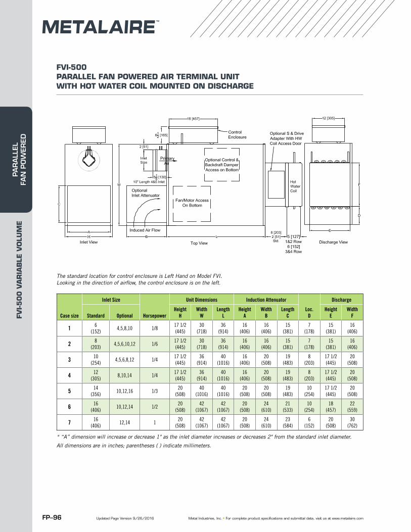
Case Inlet Size Horse Unit Unit Unit Optional Induction Attenuator DischargeSize Standard Optional Power Height Width Length Height Width Length Loc. Height Width
H W L A B C D E F1 6 (152) 4, 5, 8,10 1/8 17 1/2 (445) 30 (718) 36 (914) 16 (406) 16 (406) 15 (381) 7 (178) 15 (381) 16 (406)2 8 (203) 4,5,6,10,12 1/6 17 1/2 (445) 30 (718) 36 (914) 16 (406) 16 (406) 15 (381) 7 (178) 15 (381) 16 (406)3 10 (254) 4,5,6,8,12 1/4 17 1/2 (445) 36 (914) 40 (1016) 16 (406) 20 (508) 19 (483) 8 (203) 17 1/2 (445) 20 (508)4 12 (305) 8,10,14 1/4 17 1/2 (445) 36 (914) 40 (1016) 16 (406) 20 (508) 19 (483) 8 (203) 17 1/2 (445) 20 (508)5 14 (356) 10,12,16 1/3 20 (508) 40 (1016) 40 (1016) 20 (508) 20 (508) 19 (483) 10 (254) 17 1/2 (445) 20 (508)6 16 (406) 10,12,14 1/2 20 (508) 42 (1067) 42 (1067) 20 (508) 24 (610) 21 (533) 10 (254) 18 (457) 22 (559)7 16 (406) 12,14 1 20 (508) 42 (1067) 42 (1067) 20 (508) 24 (610) 23 (584) 6 (152) 20 (508) 30 (762)
FVI-500 PARALLEL FAN POWERED AIR TERMINAL UNIT WITH HOT WATER COIL MOUNTED ON DISCHARGE
Case size
Inlet Size
Horsepower
Unit Dimensions Induction Attenuator
Loc.D
Discharge
Standard OptionalHeight
HWidth
WLength
LHeight
AWidth
BLength
CHeight
EWidth
F
1 6 (152)
4,5,8,10 1/817 1/2 (445)
30 (718)
36 (914)
16 (406)
16 (406)
15 (381)
7 (178)
15 (381)
16 (406)
2 8 (203)
4,5,6,10,12 1/617 1/2 (445)
30 (718)
36 (914)
16 (406)
16 (406)
15 (381)
7 (178)
15 (381)
16 (406)
3 10 (254)
4,5,6,8,12 1/417 1/2 (445)
36 (914)
40 (1016)
16 (406)
20 (508)
19 (483)
8 (203)
17 1/2 (445)
20 (508)
4 12 (305)
8,10,14 1/417 1/2 (445)
36 (914)
40 (1016)
16 (406)
20 (508)
19 (483)
8 (203)
17 1/2 (445)
20 (508)
5 14 (356)
10,12,16 1/320
(508)40
(1016)40
(1016)20
(508)20
(508)19
(483)10
(254)17 1/2 (445)
20 (508)
6 16 (406)
10,12,14 1/220
(508)42
(1067)42
(1067)20
(508)24
(610)21
(533)10
(254)18
(457)22
(559)
7 16 (406)
12,14 120
(508)42
(1067)42
(1067)20
(508)24
(610)23
(584)6
(152)20
(508)30
(762)
The standard location for control enclosure is Left Hand on Model FVI. Looking in the direction of airflow, the control enclosure is on the left.
* “A” dimension will increase or decrease 1" as the inlet diameter increases or decreases 2" from the standard inlet diameter.
All dimensions are in inches; parentheses ( ) indicate millimeters.
Updated Page Version 9/26/2016
FVI-5
00
VA
RIA
BLE
VO
LUM
EPA
RA
LLEL
FA
N P
OW
ERED
FP–97© 2015 Metal Industries, Inc.
Case Inlet Size Horse Unit Unit Unit Optional Induction Attenuator DischargeSize Standard Optional Power Height Width Length Height Width Length Loc. Height Width
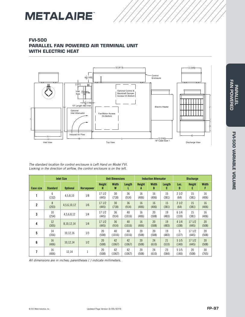
H W L A B C D E F1 6 (152) 4, 5, 8,10 1/8 17 1/2 (445) 30 (718) 36 (914) 16 (406) 16 (406) 15 (381) 2 1/2 (64) 15 (381) 16 (406)2 8 (203) 4,5,6,10,12 1/6 17 1/2 (445) 30 (718) 36 (914) 16 (406) 16 (406) 15 (381) 2 1/2 (64) 15 (381) 16 (406)3 10 (254) 4,5,6,8,12 1/4 17 1/2 (445) 36 (914) 40 (1016) 16 (406) 20 (508) 19 (483) 6 1/4 (159) 15 (381) 16 (406)4 12 (305) 8,10,12,14 1/4 17 1/2 (445) 36 (914) 40 (1016) 16 (406) 20 (508) 19 (483) 4 1/4 108) 17 1/2 (445) 20 (508)5 14 (356) 10,12,16 1/3 20 (508) 40 (1016) 40 (1016) 20 (508) 20 (508) 19 (483) 5 (127) 17 1/2 (445) 20 (508)6 16 (406) 10,12,14 1/2 20 (508) 42 (1067) 42 (1067) 20 (508) 24 (610) 21 (533) 5 1/5 (140) 17 1/2 (445) 20 (508)7 16 (406) 12,14 1 20 (508) 42 (1067) 42 (1067) 20 (508) 24 (610) 23 (584) 5 1/5 (140) 17 1/2 (445) 20 (508)
FVI-500 PARALLEL FAN POWERED AIR TERMINAL UNIT WITH ELECTRIC HEAT
Case size
Inlet Size
Horsepower
Unit Dimensions Induction Attenuator Discharge
Standard OptionalHeight
HWidth
WLength
LHeight
AWidth
BLength
CLoc.
DHeight
EWidth
F
1 6 (152)
4,5,8,10 1/817 1/2 (445)
30 (718)
36 (914)
16 (406)
16 (406)
15 (381)
2 1/2 (64)
15 (381)
16 (406)
2 8 (203)
4,5,6,10,12 1/617 1/2 (445)
30 (718)
36 (914)
16 (406)
16 (406)
15 (381)
2 1/2 (64)
15 (381)
16 (406)
3 10 (254)
4,5,6,8,12 1/417 1/2 (445)
36 (914)
40 (1016)
16 (406)
20 (508)
19 (483)
6 1/4 (159)
15 (381)
16 (406)
4 12 (305)
8,10,12,14 1/417 1/2 (445)
36 (914)
40 (1016)
16 (406)
20 (508)
19 (483)
4 1/4 (108)
17 1/2 (445)
20 (508)
5 14 (356)
10,12,16 1/320
(508)40
(1016)40
(1016)20
(508)20
(508)19
(483)5
(127)17 1/2 (445)
20 (508)
6 16 (406)
10,12,14 1/220
(508)42
(1067)42
(1067)20
(508)24
(610)21
(533)5 1/5 (140)
17 1/2 (445)
20 (508)
7 16 (406)
12,14 120
(508)42
(1067)42
(1067)20
(508)24
(610)23
(584)5 1/5 (140)
20 (508)
30 (765)
The standard location for control enclosure is Left Hand on Model FVI. Looking in the direction of airflow, the control enclosure is on the left.
All dimensions are in inches; parentheses ( ) indicate millimeters.
Updated Page Version 9/26/2016
FVI-5
00
VA
RIA
BLE
VO
LUM
EPA
RA
LLEL FA
N P
OW
ERED
FP–98 Metal Industries, Inc. ■ For complete product specifications and submittal data, visit us at www.metalaire.com
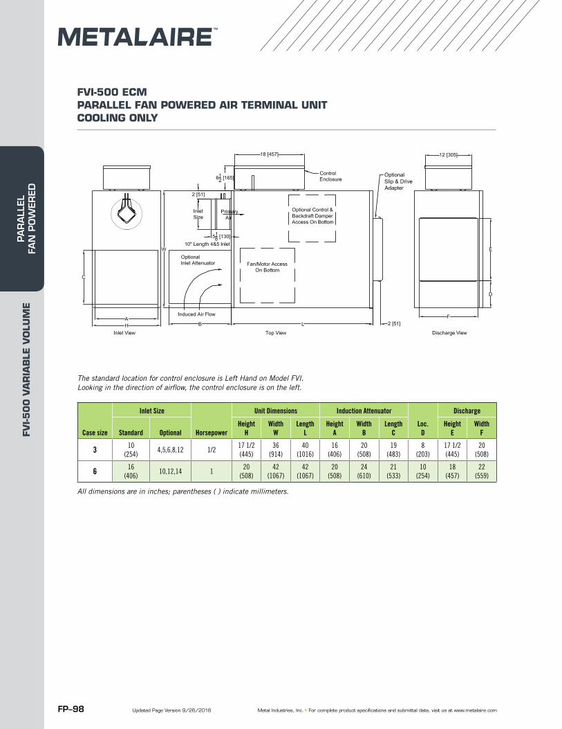
Case Inlet Size Horse Unit Unit Unit Optional Induction Attenuator DischargeSize Standard Optional Power Height Width Length Height Width Length Loc. Height Width
H W L A B C D E F3 10 (254) 4,5,6,8,12 1/2 17 1/2 (445) 36 (914) 40 (1016) 16 (406) 20 (508) 19 (483) 8 (203) 17 1/2 (445) 20 (508)6 16 (406) 10,12,14 1 20 (508) 42 (1067) 42 (1067) 20 (508) 24 (610) 21 (533) 10 (254) 18 (457) 22 (559)
FVI-500 ECM PARALLEL FAN POWERED AIR TERMINAL UNIT COOLING ONLY
Case size
Inlet Size
Horsepower
Unit Dimensions Induction Attenuator
Loc.D
Discharge
Standard OptionalHeight
HWidth
WLength
LHeight
AWidth
BLength
CHeight
EWidth
F
3 10 (254)
4,5,6,8,12 1/217 1/2 (445)
36 (914)
40 (1016)
16 (406)
20 (508)
19 (483)
8 (203)
17 1/2 (445)
20 (508)
6 16 (406)
10,12,14 120
(508)42
(1067)42
(1067)20
(508)24
(610)21
(533)10
(254)18
(457)22
(559)
The standard location for control enclosure is Left Hand on Model FVI. Looking in the direction of airflow, the control enclosure is on the left.
All dimensions are in inches; parentheses ( ) indicate millimeters.
Updated Page Version 9/26/2016
FVI-5
00
VA
RIA
BLE
VO
LUM
EPA
RA
LLEL
FA
N P
OW
ERED
FP–99© 2015 Metal Industries, Inc.
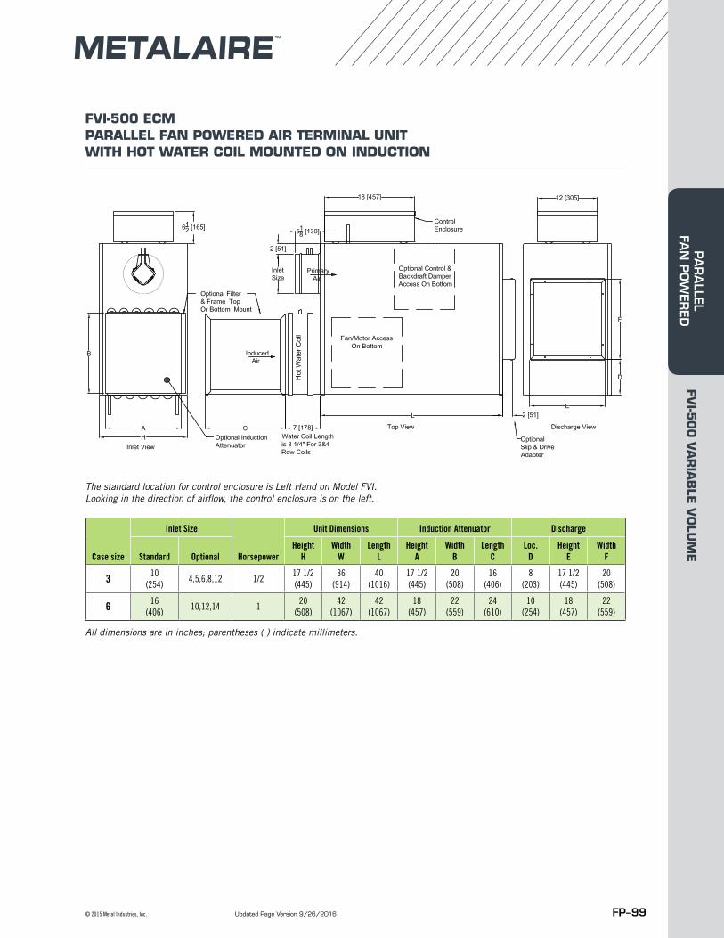
Case Inlet Size Horse Unit Unit Unit Optional Induction Attenuator DischargeSize Standard Optional Power Height Width Length Height Width Length Loc. Height Width
H W L A B C D E F3 10 (254) 4,5,6,8,12 1/2 17 1/2 (445) 36 (914) 40 (1016) 17 1/2 (445) 20 (508) 16 (406) 8 (203) 17 1/2 (445) 20 (508)6 16 (406) 10,12,14 1 20 (508) 42 (1067) 42 (1067) 18 (457) 22 (559) 24 (610) 10 (254) 18 (457) 22 (559)
FVI-500 ECM PARALLEL FAN POWERED AIR TERMINAL UNIT WITH HOT WATER COIL MOUNTED ON INDUCTION
Case size
Inlet Size
Horsepower
Unit Dimensions Induction Attenuator Discharge
Standard OptionalHeight
HWidth
WLength
LHeight
AWidth
BLength
CLoc.
DHeight
EWidth
F
3 10 (254)
4,5,6,8,12 1/217 1/2 (445)
36 (914)
40 (1016)
17 1/2 (445)
20 (508)
16 (406)
8 (203)
17 1/2 (445)
20 (508)
6 16 (406)
10,12,14 120
(508)42
(1067)42
(1067)18
(457)22
(559)24
(610)10
(254)18
(457)22
(559)
The standard location for control enclosure is Left Hand on Model FVI. Looking in the direction of airflow, the control enclosure is on the left.
All dimensions are in inches; parentheses ( ) indicate millimeters.
Updated Page Version 9/26/2016
FVI-5
00
VA
RIA
BLE
VO
LUM
EPA
RA
LLEL FA
N P
OW
ERED

FP–100 Metal Industries, Inc. ■ For complete product specifications and submittal data, visit us at www.metalaire.com
Case Inlet Size Horse Unit Unit Unit Optional Induction Attenuator DischargeSize Standard Optional Power Height Width Length Height Width Length Loc. Height Width
H W L A B C D E F1 6 (152) 4, 5, 8,10 1/8 17 1/2 (445) 30 (718) 36 (914) 16 (406) 16 (406) 15 (381) 7 (178) 15 (381) 16 (406)2 8 (203) 4,5,6,10,12 1/6 17 1/2 (445) 30 (718) 36 (914) 16 (406) 16 (406) 15 (381) 7 (178) 15 (381) 16 (406)3 10 (254) 4,5,6,8,12 1/4 17 1/2 (445) 36 (914) 40 (1016) 16 (406) 20 (508) 19 (483) 8 (203) 17 1/2 (445) 20 (508)4 12 (305) 8,10,14 1/4 17 1/2 (445) 36 (914) 40 (1016) 16 (406) 20 (508) 19 (483) 8 (203) 17 1/2 (445) 20 (508)5 14 (356) 10,12,16 1/3 20 (508) 40 (1016) 40 (1016) 20 (508) 20 (508) 19 (483) 10 (254) 17 1/2 (445) 20 (508)6 16 (406) 10,12,14 1/2 20 (508) 42 (1067) 42 (1067) 20 (508) 24 (610) 21 (533) 10 (254) 18 (457) 22 (559)7 16 (406) 12,14 1 20 (508) 42 (1067) 42 (1067) 20 (508) 24 (610) 23 (584) 6 (152) 20 (508) 30 (762)
FVI-500 ECM PARALLEL FAN POWERED AIR TERMINAL UNIT WITH HOT WATER COIL MOUNTED ON DISCHARGE
Case size
Inlet Size
Horsepower
Unit Dimensions Induction Attenuator
Loc.D
Discharge
Standard OptionalHeight
HWidth
WLength
LHeight
AWidth
BLength
CHeight
EWidth
F
3 10 (254)
4,5,6,8,12 1/217 1/2 (445)
36 (914)
40 (1016)
16 (406)
20 (508)
19 (483)
8 (203)
17 1/2 (445)
20 (508)
6 16 (406)
10,12,14 120
(508)42
(1067)42
(1067)20
(508)24
(610)21
(533)10
(254)18
(457)22
(559)
The standard location for control enclosure is Left Hand on Model FVI. Looking in the direction of airflow, the control enclosure is on the left.
All dimensions are in inches; parentheses ( ) indicate millimeters.
Updated Page Version 9/26/2016
FVI-5
00
VA
RIA
BLE
VO
LUM
EPA
RA
LLEL
FA
N P
OW
ERED
FP–101© 2015 Metal Industries, Inc.
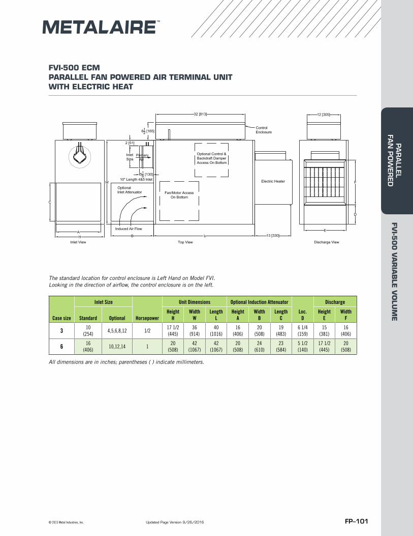
Case Inlet Size Horse Unit Unit Unit Induction Attenuator DischargeSize Standard Optional Pow er Height Width Length Height Width Length Loc. Height Width
H W L A B C D E F3 10 (254) 4,5,6,8,12,14 1/2 17 1/2 (445) 36 (914) 40 (1016) 16 (406) 20 (508) 19 (483) 6 1/4 (159) 15 (381) 16 (406)6 16 (406) 10,12,14 1 20 (508) 42 (1067) 42 (1067) 20 (508) 24 (610) 23 (584) 5 1/2 (140) 17 1/2 (445) 20 (508)
FVI-500 ECM PARALLEL FAN POWERED AIR TERMINAL UNIT WITH ELECTRIC HEAT
Case size
Inlet Size
Horsepower
Unit Dimensions Optional Induction Attenuator
Loc.D
Discharge
Standard OptionalHeight
HWidth
WLength
LHeight
AWidth
BLength
CHeight
EWidth
F
3 10 (254)
4,5,6,8,12 1/217 1/2 (445)
36 (914)
40 (1016)
16 (406)
20 (508)
19 (483)
6 1/4 (159)
15 (381)
16 (406)
6 16 (406)
10,12,14 120
(508)42
(1067)42
(1067)20
(508)24
(610)23
(584)5 1/2 (140)
17 1/2 (445)
20 (508)
The standard location for control enclosure is Left Hand on Model FVI. Looking in the direction of airflow, the control enclosure is on the left.
All dimensions are in inches; parentheses ( ) indicate millimeters.
Updated Page Version 9/26/2016
FVI-5
00
VA
RIA
BLE
VO
LUM
EPA
RA
LLEL FA
N P
OW
ERED
FP–102 Metal Industries, Inc. ■ For complete product specifications and submittal data, visit us at www.metalaire.com
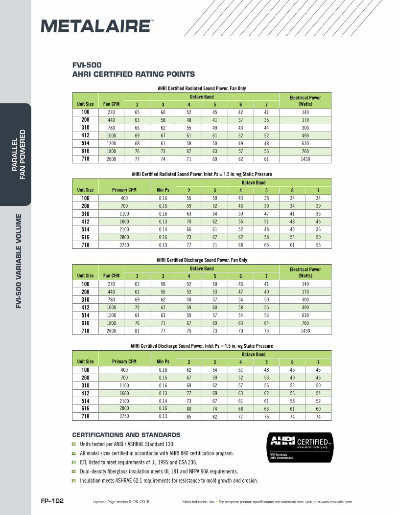
FVI-500 AHRI CERTIFIED RATING POINTS
AHRI Certified Radiated Sound Power, Fan Only
Unit Size Fan CFMOctave Band Electrical Power
(Watts)2 3 4 5 6 7106 270 65 60 52 45 42 41 140
208 440 63 58 48 41 37 35 170
310 780 66 62 55 49 43 44 300
412 1000 69 67 61 61 52 52 490
514 1200 68 61 58 50 49 48 630
616 1800 76 73 67 63 57 56 760
718 2600 77 74 71 69 62 61 1430
AHRI Certified Radiated Sound Power, Inlet Ps = 1.5 in. wg Static Pressure
Unit Size Primary CFM Min PsOctave Band
2 3 4 5 6 7
106 400 0.16 56 50 43 38 34 34
208 700 0.15 59 52 43 39 34 29
310 1100 0.16 63 54 50 47 41 35
412 1600 0.13 70 62 55 51 48 45
514 2100 0.14 66 61 52 48 43 36
616 2800 0.16 73 67 62 58 54 50
718 3750 0.13 77 71 68 65 61 56
AHRI Certified Discharge Sound Power, Fan Only
Unit Size Fan CFMOctave Band Electrical Power
(Watts)2 3 4 5 6 7
106 270 63 58 52 50 46 41 140
208 440 62 56 52 53 47 40 170
310 780 69 62 58 57 54 50 300
412 1000 72 67 59 60 58 55 490
514 1200 64 63 59 57 54 53 630
616 1800 76 71 67 69 63 64 760
718 2600 81 77 75 73 70 73 1430
AHRI Certified Discharge Sound Power, Inlet Ps = 1.5 in. wg Static Pressure
Unit Size Primary CFM Min PsOctave Band
2 3 4 5 6 7
106 400 0.16 62 54 51 48 45 45
208 700 0.15 67 59 52 53 49 45
310 1100 0.16 69 62 57 56 53 50
412 1600 0.13 77 69 63 62 56 54
514 2100 0.14 73 67 61 61 58 52
616 2800 0.16 80 74 68 63 61 60
718 3750 0.13 85 82 77 76 74 74
CERTIFICATIONS AND STANDARDS■ Units tested per ANSI / ASHRAE Standard 130.■ All model sizes certified in accordance with AHRI 880 certification program.■ ETL listed to meet requirements of UL 1995 and CSA 236.■ Dual-density fiberglass insulation meets UL 181 and NFPA 90A requirements.■ Insulation meets ASHRAE 62.1 requirements for resistance to mold growth and erosion.
Updated Page Version 9/26/2016
FVI-5
00
VA
RIA
BLE
VO
LUM
EPA
RA
LLEL
FA
N P
OW
ERED
FP–103© 2015 Metal Industries, Inc.
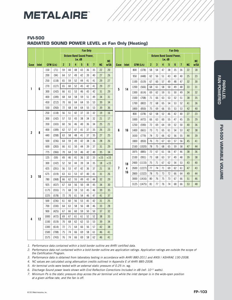
FVI-500RADIATED SOUND POWER LEVEL at Fan Only (Heating)
1. Performance data contained within a bold border outline are AHRI certified data.2. Performance data not contained within a bold border outline are application ratings. Application ratings are outside the scope of
the Certification Program.3. Performance data is obtained from laboratory testing in accordance with AHRI 880-2011 and ANSI / ASHRAE 130-2008.4. NC values are calculated using attenuation credits outlined in Appendix E of AHRI 885-2008. 5. Air terminal units were tested with an external static pressure of 0.25 in. wg.6. Discharge Sound power levels shown with End Reflection Corrections Included in dB (ref: 10-12 watts). 7. Minimum Ps is the static pressure drop across the air terminal unit while the inlet damper is in the wide-open position
at a given airflow rate, and the fan is off.
Case Inlet CFM (L/s)
Fan Only
Octave Band Sound Power, Lw, dB
NCNC
w/SA2 3 4 5 6 7
1 6
150 (71) 59 44 48 43 36 35 22 20
200 (94) 64 57 49 42 39 40 27 26
250 (118) 65 59 52 44 41 41 29 27
270 (127) 65 60 52 45 42 41 29 27
300 (142) 66 61 53 46 43 42 31 29
400 (189) 68 64 58 59 51 49 34 31
450 (212) 70 66 64 64 55 53 39 34
550 (260) 72 68 64 64 55 53 39 36
2 8
250 (118) 56 51 42 37 33 32 19 16
300 (142) 57 53 43 38 34 32 21 17
350 (165) 60 56 46 40 36 34 25 21
400 (189) 62 57 47 41 37 35 26 23
440 (208) 63 58 48 41 37 35 27 25
500 (236) 64 59 49 42 38 36 28 26
600 (283) 66 61 50 44 39 37 31 29
775 (366) 70 64 53 46 42 40 35 34
3 10
125 (59) 49 46 41 36 32 33 <15 <15
300 (142) 52 50 44 39 34 35 18 <15
425 (201) 56 53 47 42 36 37 21 16
675 (319) 63 61 53 47 40 41 31 26
780 (368) 66 62 55 49 43 44 32 29
925 (437) 67 64 56 50 44 45 34 30
1175 (555) 71 68 59 53 45 46 39 35
1225 (578) 72 70 61 54 46 47 41 37
4 12
500 (236) 61 60 56 53 45 42 31 25
700 (330) 64 63 58 56 48 46 33 28
900 (425) 67 66 60 59 50 50 37 32
1000 (472) 69 67 61 61 52 52 38 33
1100 (519) 70 68 62 62 53 53 39 34
1300 (614) 72 71 64 66 56 57 42 38
1500 (708) 75 74 66 69 58 61 46 41
1575 (743) 76 74 66 69 58 62 46 41
Case Inlet CFM (L/s)
Fan Only
Octave Band Sound Power, Lw, dB
NCNC
w/SA2 3 4 5 6 7
5 14
800 (378) 58 54 47 38 35 36 22 18
950 (448) 62 56 51 43 40 40 25 23
1100 (519) 67 60 57 49 48 47 32 30
1200 (566) 68 61 58 50 49 48 33 31
1300 (614) 69 62 59 51 50 49 34 32
1500 (708) 71 66 63 53 52 51 38 35
1700 (802) 72 68 65 54 53 52 41 36
1800 (850) 75 69 66 55 53 53 42 40
6 16
800 (378) 62 58 52 46 42 40 27 23
1000 (472) 66 63 60 55 47 45 35 29
1250 (590) 72 69 64 59 52 50 40 36
1400 (661) 73 71 65 61 54 53 42 38
1650 (779) 74 72 66 62 56 55 44 39
1800 (850) 76 73 67 63 57 56 45 41
2160 (1020) 78 75 68 65 59 58 47 44
718x
16
1875 (885) 72 67 61 56 47 46 38 36
2100 (991) 73 68 63 57 49 48 39 38
2400 (1133) 75 71 67 62 54 53 43 40
2600 (1227) 77 74 71 69 62 61 47 43
2800 (1322) 78 75 73 72 66 64 49 44
3000 (1416) 80 76 75 73 67 66 51 46
3125 (1475) 81 77 76 74 68 66 53 48
FVI-5
00
VA
RIA
BLE
VO
LUM
EPA
RA
LLEL FA
N P
OW
ERED
FP–104 Metal Industries, Inc. ■ For complete product specifications and submittal data, visit us at www.metalaire.com
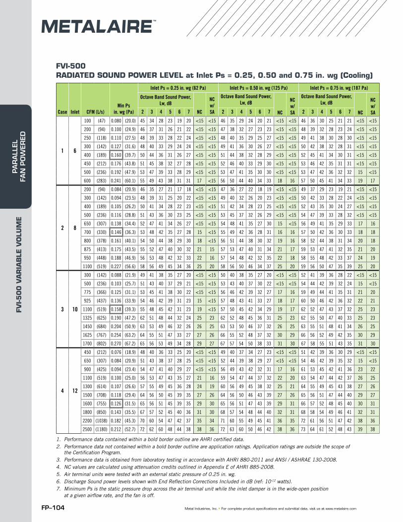
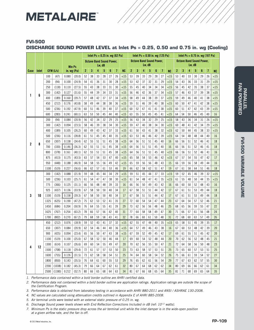
FVI-500RADIATED SOUND POWER LEVEL at Inlet Ps = 0.25, 0.50 and 0.75 in. wg (Cooling)
1. Performance data contained within a bold border outline are AHRI certified data.2. Performance data not contained within a bold border outline are application ratings. Application ratings are outside the scope of
the Certification Program.3. Performance data is obtained from laboratory testing in accordance with AHRI 880-2011 and ANSI / ASHRAE 130-2008.4. NC values are calculated using attenuation credits outlined in Appendix E of AHRI 885-2008. 5. Air terminal units were tested with an external static pressure of 0.25 in. wg.6. Discharge Sound power levels shown with End Reflection Corrections Included in dB (ref: 10-12 watts). 7. Minimum Ps is the static pressure drop across the air terminal unit while the inlet damper is in the wide-open position
at a given airflow rate, and the fan is off.
Case Inlet CFM (L/s)Min Ps
in. wg (Pa)
Inlet Ps = 0.25 in. wg (62 Pa) Inlet Ps = 0.50 in. wg (125 Pa) Inlet Ps = 0.75 in. wg (187 Pa)
Octave Band Sound Power, Lw, dB
NC
NC w/SA
Octave Band Sound Power, Lw, dB
NC
NC w/SA
Octave Band Sound Power, Lw, dB
NC
NC w/SA2 3 4 5 6 7 2 3 4 5 6 7 2 3 4 5 6 7
1 6
100 (47) 0.080 (20.0) 45 34 28 23 19 20 <15 <15 46 35 29 24 20 21 <15 <15 46 36 30 25 21 21 <15 <15
200 (94) 0.100 (24.9) 46 37 31 26 21 22 <15 <15 47 38 32 27 23 23 <15 <15 48 39 32 28 23 24 <15 <15
250 (118) 0.110 (27.5) 48 39 33 28 22 24 <15 <15 48 40 35 29 25 27 <15 <15 49 41 38 30 28 30 <15 <15
300 (142) 0.127 (31.6) 48 40 33 29 24 24 <15 <15 49 41 36 30 26 27 <15 <15 50 42 38 32 28 31 <15 <15
400 (189) 0.160 (39.7) 50 44 36 31 26 27 <15 <15 51 44 38 32 28 29 <15 <15 52 45 41 34 30 31 <15 <15
450 (212) 0.176 (43.8) 51 45 38 32 27 28 <15 <15 52 46 40 33 29 30 <15 <15 53 46 42 35 31 31 <15 <15
500 (236) 0.192 (47.9) 53 47 39 33 28 29 <15 <15 53 47 41 35 30 30 <15 <15 53 47 42 36 32 32 15 <15
600 (283) 0.241 (60.1) 55 49 43 38 31 31 17 <15 56 50 44 40 34 33 18 16 57 50 45 41 34 33 19 17
2 8
200 (94) 0.084 (20.9) 46 35 27 21 17 18 <15 <15 47 36 27 22 18 19 <15 <15 49 37 29 23 19 21 <15 <15
300 (142) 0.094 (23.5) 48 39 31 25 20 22 <15 <15 49 40 32 26 20 23 <15 <15 50 42 33 28 22 24 <15 <15
400 (189) 0.105 (26.2) 50 41 34 28 22 23 <15 <15 51 42 34 28 23 25 <15 <15 52 43 35 30 24 27 <15 <15
500 (236) 0.116 (28.8) 51 43 36 30 23 25 <15 <15 53 45 37 32 26 29 <15 <15 54 47 39 33 28 32 <15 <15
650 (307) 0.138 (34.4) 52 47 41 34 26 27 <15 <15 54 48 41 35 27 30 15 <15 56 49 41 35 29 33 17 16
700 (330) 0.146 (36.3) 53 48 42 35 27 28 15 <15 55 49 42 36 28 31 16 16 57 50 42 36 30 33 18 18
800 (378) 0.161 (40.1) 54 50 44 38 29 30 18 <15 56 51 44 38 30 32 19 16 58 52 44 38 31 34 20 18
875 (413) 0.175 (43.5) 55 52 47 40 30 32 21 15 57 53 47 40 31 34 21 17 59 53 47 41 32 35 21 20
950 (448) 0.188 (46.9) 56 53 48 42 32 33 22 16 57 54 48 42 32 35 22 18 58 55 48 42 33 37 24 19
1100 (519) 0.227 (56.6) 58 56 49 45 34 36 25 20 58 56 50 46 34 37 25 20 59 56 50 47 35 39 25 20
3 10
300 (142) 0.088 (21.9) 49 41 38 35 27 20 <15 <15 50 40 38 35 27 20 <15 <15 52 41 39 36 28 22 <15 <15
500 (236) 0.103 (25.7) 51 43 40 37 29 21 <15 <15 53 43 40 37 30 22 <15 <15 54 44 42 39 32 24 15 <15
775 (366) 0.125 (31.1) 53 45 41 38 30 22 <15 <15 56 46 42 39 32 27 17 16 59 49 44 41 35 31 21 20
925 (437) 0.136 (33.9) 54 46 42 39 31 23 15 <15 57 48 43 41 33 27 18 17 60 50 46 42 36 32 22 21
1100 (519) 0.158 (39.3) 55 48 45 42 31 23 19 <15 57 50 45 42 34 29 19 17 62 52 47 43 37 32 25 23
1325 (625) 0.190 (47.2) 62 51 48 44 32 24 25 23 62 52 48 45 36 31 25 23 62 55 50 47 40 33 25 23
1450 (684) 0.204 (50.9) 63 53 49 46 32 26 26 25 63 53 50 46 37 32 26 25 63 55 51 48 41 34 26 25
1625 (767) 0.254 (63.2) 64 55 51 47 33 27 27 26 66 55 52 48 37 32 30 29 66 56 52 49 42 35 30 29
1700 (802) 0.270 (67.2) 65 56 53 49 34 28 29 27 67 57 54 50 38 33 31 30 67 58 55 51 43 35 31 30
4 12
450 (212) 0.076 (18.9) 48 40 36 33 25 20 <15 <15 49 40 37 34 27 23 <15 <15 51 42 39 36 30 29 <15 <15
650 (307) 0.084 (20.9) 51 43 38 37 28 25 <15 <15 52 44 39 38 29 27 <15 <15 54 46 42 39 35 32 15 <15
900 (425) 0.094 (23.4) 54 47 41 40 29 27 <15 <15 56 49 43 42 32 31 17 16 61 53 45 42 41 36 23 22
1100 (519) 0.100 (25.0) 56 53 47 43 35 27 21 16 59 54 47 44 37 32 22 20 63 54 47 44 42 37 26 25
1300 (614) 0.107 (26.6) 57 55 49 45 36 28 24 19 60 56 49 45 38 32 25 21 64 55 49 45 43 38 27 26
1500 (708) 0.118 (29.4) 64 56 50 45 39 35 27 26 64 56 50 46 43 39 27 26 65 56 51 47 44 40 29 27
1600 (755) 0.126 (31.5) 65 56 51 45 39 35 29 30 65 56 51 47 43 39 29 31 66 57 52 48 45 40 30 31
1800 (850) 0.143 (35.5) 67 57 52 45 40 36 31 30 68 57 54 48 44 40 32 31 68 58 54 49 46 41 32 31
2200 (1038) 0.182 (45.3) 70 60 54 47 42 37 35 34 71 60 55 49 45 41 36 35 72 61 56 51 47 42 38 36
2500 (1180) 0.212 (52.7) 72 62 60 48 44 38 38 36 72 63 60 50 46 42 38 36 73 64 61 52 48 43 39 38
FVI-5
00
VA
RIA
BLE
VO
LUM
EPA
RA
LLEL
FA
N P
OW
ERED
FP–105© 2015 Metal Industries, Inc.
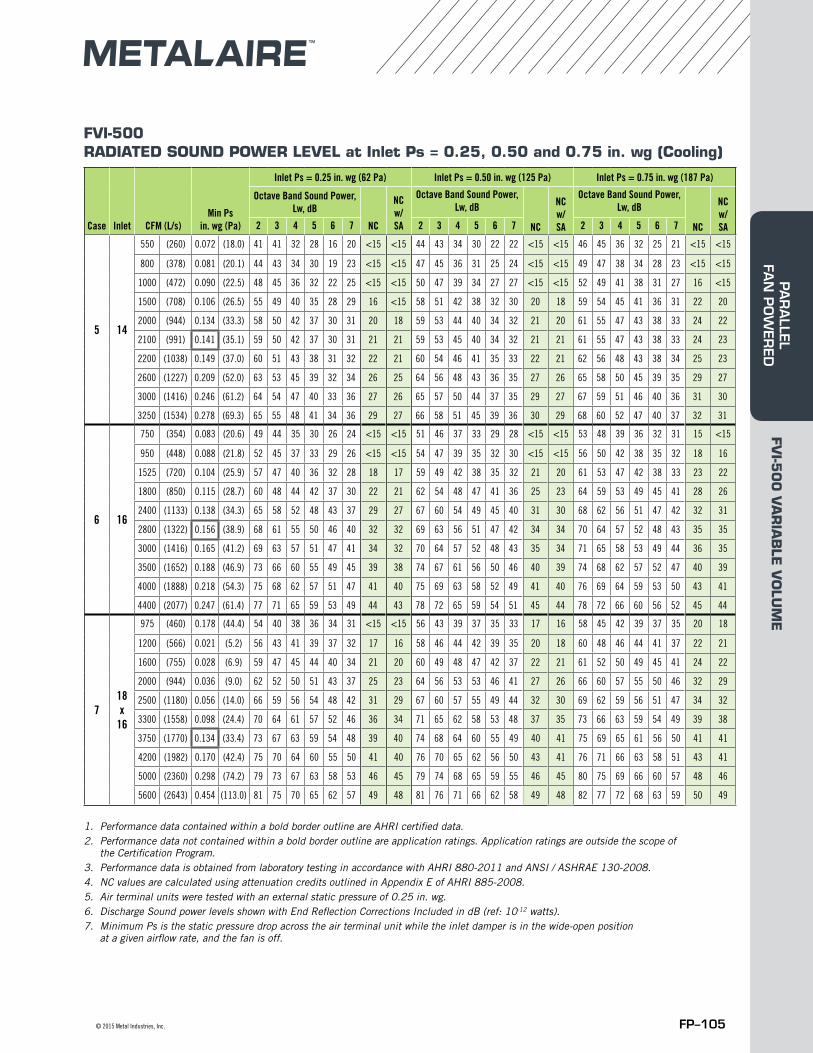
FVI-500RADIATED SOUND POWER LEVEL at Inlet Ps = 0.25, 0.50 and 0.75 in. wg (Cooling)
1. Performance data contained within a bold border outline are AHRI certified data.2. Performance data not contained within a bold border outline are application ratings. Application ratings are outside the scope of
the Certification Program.3. Performance data is obtained from laboratory testing in accordance with AHRI 880-2011 and ANSI / ASHRAE 130-2008.4. NC values are calculated using attenuation credits outlined in Appendix E of AHRI 885-2008. 5. Air terminal units were tested with an external static pressure of 0.25 in. wg.6. Discharge Sound power levels shown with End Reflection Corrections Included in dB (ref: 10-12 watts). 7. Minimum Ps is the static pressure drop across the air terminal unit while the inlet damper is in the wide-open position
at a given airflow rate, and the fan is off.
Case Inlet CFM (L/s)Min Ps
in. wg (Pa)
Inlet Ps = 0.25 in. wg (62 Pa) Inlet Ps = 0.50 in. wg (125 Pa) Inlet Ps = 0.75 in. wg (187 Pa)
Octave Band Sound Power, Lw, dB
NC
NC w/SA
Octave Band Sound Power, Lw, dB
NC
NC w/SA
Octave Band Sound Power, Lw, dB
NC
NC w/SA2 3 4 5 6 7 2 3 4 5 6 7 2 3 4 5 6 7
5 14
550 (260) 0.072 (18.0) 41 41 32 28 16 20 <15 <15 44 43 34 30 22 22 <15 <15 46 45 36 32 25 21 <15 <15
800 (378) 0.081 (20.1) 44 43 34 30 19 23 <15 <15 47 45 36 31 25 24 <15 <15 49 47 38 34 28 23 <15 <15
1000 (472) 0.090 (22.5) 48 45 36 32 22 25 <15 <15 50 47 39 34 27 27 <15 <15 52 49 41 38 31 27 16 <15
1500 (708) 0.106 (26.5) 55 49 40 35 28 29 16 <15 58 51 42 38 32 30 20 18 59 54 45 41 36 31 22 20
2000 (944) 0.134 (33.3) 58 50 42 37 30 31 20 18 59 53 44 40 34 32 21 20 61 55 47 43 38 33 24 22
2100 (991) 0.141 (35.1) 59 50 42 37 30 31 21 21 59 53 45 40 34 32 21 21 61 55 47 43 38 33 24 23
2200 (1038) 0.149 (37.0) 60 51 43 38 31 32 22 21 60 54 46 41 35 33 22 21 62 56 48 43 38 34 25 23
2600 (1227) 0.209 (52.0) 63 53 45 39 32 34 26 25 64 56 48 43 36 35 27 26 65 58 50 45 39 35 29 27
3000 (1416) 0.246 (61.2) 64 54 47 40 33 36 27 26 65 57 50 44 37 35 29 27 67 59 51 46 40 36 31 30
3250 (1534) 0.278 (69.3) 65 55 48 41 34 36 29 27 66 58 51 45 39 36 30 29 68 60 52 47 40 37 32 31
6 16
750 (354) 0.083 (20.6) 49 44 35 30 26 24 <15 <15 51 46 37 33 29 28 <15 <15 53 48 39 36 32 31 15 <15
950 (448) 0.088 (21.8) 52 45 37 33 29 26 <15 <15 54 47 39 35 32 30 <15 <15 56 50 42 38 35 32 18 16
1525 (720) 0.104 (25.9) 57 47 40 36 32 28 18 17 59 49 42 38 35 32 21 20 61 53 47 42 38 33 23 22
1800 (850) 0.115 (28.7) 60 48 44 42 37 30 22 21 62 54 48 47 41 36 25 23 64 59 53 49 45 41 28 26
2400 (1133) 0.138 (34.3) 65 58 52 48 43 37 29 27 67 60 54 49 45 40 31 30 68 62 56 51 47 42 32 31
2800 (1322) 0.156 (38.9) 68 61 55 50 46 40 32 32 69 63 56 51 47 42 34 34 70 64 57 52 48 43 35 35
3000 (1416) 0.165 (41.2) 69 63 57 51 47 41 34 32 70 64 57 52 48 43 35 34 71 65 58 53 49 44 36 35
3500 (1652) 0.188 (46.9) 73 66 60 55 49 45 39 38 74 67 61 56 50 46 40 39 74 68 62 57 52 47 40 39
4000 (1888) 0.218 (54.3) 75 68 62 57 51 47 41 40 75 69 63 58 52 49 41 40 76 69 64 59 53 50 43 41
4400 (2077) 0.247 (61.4) 77 71 65 59 53 49 44 43 78 72 65 59 54 51 45 44 78 72 66 60 56 52 45 44
718x
16
975 (460) 0.178 (44.4) 54 40 38 36 34 31 <15 <15 56 43 39 37 35 33 17 16 58 45 42 39 37 35 20 18
1200 (566) 0.021 (5.2) 56 43 41 39 37 32 17 16 58 46 44 42 39 35 20 18 60 48 46 44 41 37 22 21
1600 (755) 0.028 (6.9) 59 47 45 44 40 34 21 20 60 49 48 47 42 37 22 21 61 52 50 49 45 41 24 22
2000 (944) 0.036 (9.0) 62 52 50 51 43 37 25 23 64 56 53 53 46 41 27 26 66 60 57 55 50 46 32 29
2500 (1180) 0.056 (14.0) 66 59 56 54 48 42 31 29 67 60 57 55 49 44 32 30 69 62 59 56 51 47 34 32
3300 (1558) 0.098 (24.4) 70 64 61 57 52 46 36 34 71 65 62 58 53 48 37 35 73 66 63 59 54 49 39 38
3750 (1770) 0.134 (33.4) 73 67 63 59 54 48 39 40 74 68 64 60 55 49 40 41 75 69 65 61 56 50 41 41
4200 (1982) 0.170 (42.4) 75 70 64 60 55 50 41 40 76 70 65 62 56 50 43 41 76 71 66 63 58 51 43 41
5000 (2360) 0.298 (74.2) 79 73 67 63 58 53 46 45 79 74 68 65 59 55 46 45 80 75 69 66 60 57 48 46
5600 (2643) 0.454 (113.0) 81 75 70 65 62 57 49 48 81 76 71 66 62 58 49 48 82 77 72 68 63 59 50 49
FVI-5
00
VA
RIA
BLE
VO
LUM
EPA
RA
LLEL FA
N P
OW
ERED
FP–106 Metal Industries, Inc. ■ For complete product specifications and submittal data, visit us at www.metalaire.com
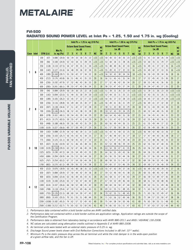
FVI-500RADIATED SOUND POWER LEVEL at Inlet Ps = 1.25, 1.50 and 1.75 in. wg (Cooling)
1. Performance data contained within a bold border outline are AHRI certified data.2. Performance data not contained within a bold border outline are application ratings. Application ratings are outside the scope of
the Certification Program.3. Performance data is obtained from laboratory testing in accordance with AHRI 880-2011 and ANSI / ASHRAE 130-2008.4. NC values are calculated using attenuation credits outlined in Appendix E of AHRI 885-2008. 5. Air terminal units were tested with an external static pressure of 0.25 in. wg.6. Discharge Sound power levels shown with End Reflection Corrections Included in dB (ref: 10-12 watts). 7. Minimum Ps is the static pressure drop across the air terminal unit while the inlet damper is in the wide-open position
at a given airflow rate, and the fan is off.
Case Inlet CFM (L/s)Min Ps
in. wg (Pa)
Inlet Ps = 1.25 in. wg (310 Pa) Inlet Ps = 1.50 in. wg (375 Pa) Inlet Ps = 1.75 in. wg (435 Pa)
Octave Band Sound Power, Lw, dB
NC
NC w/SA
Octave Band Sound Power, Lw, dB
NC
NC w/SA
Octave Band Sound Power, Lw, dB
NC
NC w/SA2 3 4 5 6 7 2 3 4 5 6 7 2 3 4 5 6 7
1 6
100 (47) 0.080 (20.0) 50 39 33 30 25 22 <15 <15 50 40 33 30 26 23 <15 <15 51 41 33 30 26 24 <15 <15
200 (94) 0.100 (24.9) 52 43 34 31 28 25 <15 <15 53 44 34 31 28 26 <15 <15 53 44 35 31 29 27 <15 <15
250 (118) 0.110 (27.5) 54 47 39 35 31 30 <15 <15 55 48 40 36 32 33 16 <15 55 49 41 37 32 35 16 <15
300 (142) 0.127 (31.6) 54 48 39 36 32 30 15 <15 55 49 41 37 32 33 16 <15 55 49 42 37 33 35 16 <15
400 (189) 0.160 (39.7) 55 50 42 37 34 32 18 <15 56 50 43 38 34 34 18 <15 56 50 43 39 34 36 18 16
450 (212) 0.176 (43.8) 56 51 46 41 35 33 20 16 56 51 45 41 35 34 19 17 57 52 45 41 35 36 20 17
500 (236) 0.192 (47.9) 57 52 46 43 36 33 20 17 57 52 46 42 36 34 20 17 58 53 46 41 36 36 21 18
600 (283) 0.241 (60.1) 58 53 47 43 36 34 21 18 58 53 47 43 37 34 21 20 59 54 47 43 37 35 22 20
2 8
200 (94) 0.084 (20.9) 50 39 30 25 22 18 <15 <15 51 39 31 26 23 19 <15 <15 51 39 31 26 23 20 <15 <15
300 (142) 0.094 (23.5) 51 44 35 30 24 20 <15 <15 52 44 35 31 25 21 <15 <15 52 43 35 31 26 21 <15 <15
400 (189) 0.105 (26.2) 53 45 37 32 27 22 <15 <15 54 45 37 33 28 23 <15 <15 54 45 37 33 29 24 <15 <15
500 (236) 0.116 (28.8) 55 49 40 35 30 27 16 <15 56 49 41 36 31 29 17 <15 56 49 41 37 32 30 17 16
650 (307) 0.138 (34.4) 57 51 42 37 32 28 19 17 58 51 43 38 33 29 20 18 59 51 43 39 34 30 21 20
700 (330) 0.146 (36.3) 58 52 43 38 33 28 20 20 59 52 43 39 34 29 21 21 60 52 44 40 35 30 22 22
800 (378) 0.161 (40.1) 59 54 45 39 34 29 22 20 60 54 45 40 35 30 22 21 61 54 45 41 36 31 23 22
875 (413) 0.175 (43.5) 59 55 47 41 34 29 24 20 61 55 47 42 35 30 24 22 62 55 46 43 36 31 25 23
950 (448) 0.188 (46.9) 59 56 49 43 35 29 25 20 60 56 49 44 36 31 25 21 61 55 49 44 37 32 24 22
1100 (519) 0.227 (56.6) 60 57 50 49 37 29 26 21 61 57 50 50 38 31 26 22 62 56 49 50 38 33 25 23
3 10
300 (142) 0.088 (21.9) 54 42 40 39 31 23 <15 <15 55 43 41 40 32 25 16 <15 56 44 42 40 33 26 17 16
500 (236) 0.103 (25.7) 56 45 43 41 34 25 17 16 57 46 44 42 35 27 18 17 57 47 44 43 36 28 18 17
775 (366) 0.125 (31.1) 60 50 45 43 37 32 22 21 61 52 47 45 39 34 23 22 61 53 48 46 40 35 23 22
925 (437) 0.136 (33.9) 62 51 46 45 38 33 25 23 62 53 48 46 39 34 25 23 62 55 50 47 40 35 25 23
1100 (519) 0.158 (39.3) 63 52 47 46 40 34 26 25 63 54 50 47 41 35 26 25 63 56 52 48 41 36 26 25
1325 (625) 0.190 (47.2) 64 55 54 49 43 35 29 26 64 56 55 49 43 36 30 26 64 56 55 49 43 36 30 26
1450 (684) 0.204 (50.9) 64 55 53 50 44 36 27 26 65 56 55 50 44 36 30 27 65 57 56 50 44 36 31 27
1625 (767) 0.254 (63.2) 67 57 54 50 44 36 31 30 68 58 55 51 45 37 32 30 68 59 56 52 45 38 32 31
1700 (802) 0.270 (67.2) 68 59 56 52 45 38 32 31 69 60 57 53 46 39 34 32 69 60 57 54 46 39 34 32
4 12
450 (212) 0.076 (18.9) 53 45 40 38 35 32 <15 <15 55 47 42 39 37 34 16 <15 56 49 43 40 39 35 17 16
650 (307) 0.084 (20.9) 57 50 44 42 39 36 18 17 59 53 46 44 41 38 21 20 60 55 48 45 42 40 24 21
900 (425) 0.094 (23.4) 63 56 49 45 43 41 26 25 65 58 51 47 45 43 29 27 66 59 53 49 47 45 30 29
1100 (519) 0.100 (25.0) 65 57 50 47 44 42 29 27 67 59 52 49 46 44 31 30 68 61 54 50 48 46 32 31
1300 (614) 0.107 (26.6) 66 58 52 48 45 42 30 29 68 60 54 50 47 44 32 30 69 62 55 51 49 46 34 32
1500 (708) 0.118 (29.4) 67 59 53 49 46 43 31 30 69 61 55 51 48 45 34 32 71 63 56 52 49 47 36 35
1600 (755) 0.126 (31.5) 68 60 54 50 47 43 32 34 70 62 55 51 48 45 35 35 71 63 56 52 49 47 36 36
1800 (850) 0.143 (35.5) 70 61 55 51 48 44 35 34 71 63 56 52 49 46 36 35 72 64 57 53 50 47 38 36
2200 (1038) 0.182 (45.3) 74 62 57 52 49 43 40 39 75 64 58 54 50 46 41 40 76 65 58 55 51 48 43 41
2500 (1180) 0.212 (52.7) 75 65 62 53 50 45 41 40 76 66 63 55 51 47 43 41 77 67 63 57 52 49 44 43
FVI-5
00
VA
RIA
BLE
VO
LUM
EPA
RA
LLEL
FA
N P
OW
ERED
FP–107© 2015 Metal Industries, Inc.
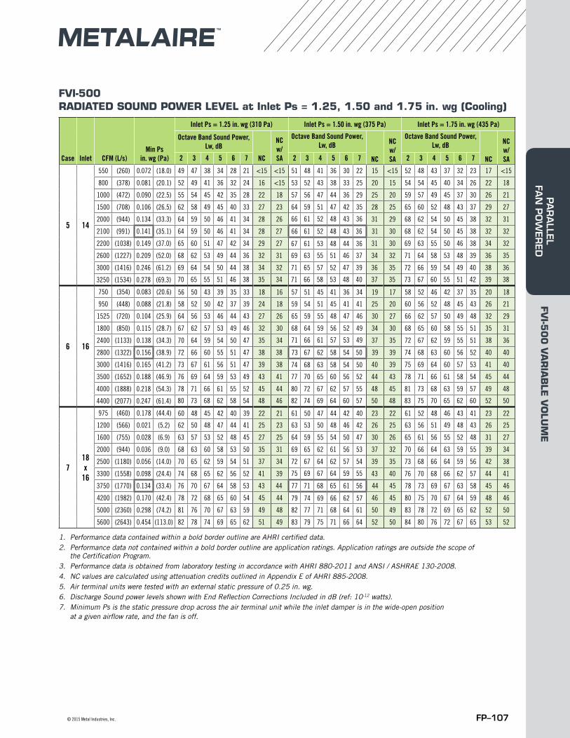
FVI-500RADIATED SOUND POWER LEVEL at Inlet Ps = 1.25, 1.50 and 1.75 in. wg (Cooling)
1. Performance data contained within a bold border outline are AHRI certified data.2. Performance data not contained within a bold border outline are application ratings. Application ratings are outside the scope of
the Certification Program.3. Performance data is obtained from laboratory testing in accordance with AHRI 880-2011 and ANSI / ASHRAE 130-2008.4. NC values are calculated using attenuation credits outlined in Appendix E of AHRI 885-2008. 5. Air terminal units were tested with an external static pressure of 0.25 in. wg.6. Discharge Sound power levels shown with End Reflection Corrections Included in dB (ref: 10-12 watts). 7. Minimum Ps is the static pressure drop across the air terminal unit while the inlet damper is in the wide-open position
at a given airflow rate, and the fan is off.
Case Inlet CFM (L/s)Min Ps
in. wg (Pa)
Inlet Ps = 1.25 in. wg (310 Pa) Inlet Ps = 1.50 in. wg (375 Pa) Inlet Ps = 1.75 in. wg (435 Pa)
Octave Band Sound Power, Lw, dB
NC
NC w/SA
Octave Band Sound Power, Lw, dB
NC
NC w/SA
Octave Band Sound Power, Lw, dB
NC
NC w/SA2 3 4 5 6 7 2 3 4 5 6 7 2 3 4 5 6 7
5 14
550 (260) 0.072 (18.0) 49 47 38 34 28 21 <15 <15 51 48 41 36 30 22 15 <15 52 48 43 37 32 23 17 <15
800 (378) 0.081 (20.1) 52 49 41 36 32 24 16 <15 53 52 43 38 33 25 20 15 54 54 45 40 34 26 22 18
1000 (472) 0.090 (22.5) 55 54 45 42 35 28 22 18 57 56 47 44 36 29 25 20 59 57 49 45 37 30 26 21
1500 (708) 0.106 (26.5) 62 58 49 45 40 33 27 23 64 59 51 47 42 35 28 25 65 60 52 48 43 37 29 27
2000 (944) 0.134 (33.3) 64 59 50 46 41 34 28 26 66 61 52 48 43 36 31 29 68 62 54 50 45 38 32 31
2100 (991) 0.141 (35.1) 64 59 50 46 41 34 28 27 66 61 52 48 43 36 31 30 68 62 54 50 45 38 32 32
2200 (1038) 0.149 (37.0) 65 60 51 47 42 34 29 27 67 61 53 48 44 36 31 30 69 63 55 50 46 38 34 32
2600 (1227) 0.209 (52.0) 68 62 53 49 44 36 32 31 69 63 55 51 46 37 34 32 71 64 58 53 48 39 36 35
3000 (1416) 0.246 (61.2) 69 64 54 50 44 38 34 32 71 65 57 52 47 39 36 35 72 66 59 54 49 40 38 36
3250 (1534) 0.278 (69.3) 70 65 55 51 46 38 35 34 71 66 58 53 48 40 37 35 73 67 60 55 51 42 39 38
6 16
750 (354) 0.083 (20.6) 56 50 43 39 35 33 18 16 57 51 45 41 36 34 19 17 58 52 46 42 37 35 20 18
950 (448) 0.088 (21.8) 58 52 50 42 37 39 24 18 59 54 51 45 41 41 25 20 60 56 52 48 45 43 26 21
1525 (720) 0.104 (25.9) 64 56 53 46 44 43 27 26 65 59 55 48 47 46 30 27 66 62 57 50 49 48 32 29
1800 (850) 0.115 (28.7) 67 62 57 53 49 46 32 30 68 64 59 56 52 49 34 30 68 65 60 58 55 51 35 31
2400 (1133) 0.138 (34.3) 70 64 59 54 50 47 35 34 71 66 61 57 53 49 37 35 72 67 62 59 55 51 38 36
2800 (1322) 0.156 (38.9) 72 66 60 55 51 47 38 38 73 67 62 58 54 50 39 39 74 68 63 60 56 52 40 40
3000 (1416) 0.165 (41.2) 73 67 61 56 51 47 39 38 74 68 63 58 54 50 40 39 75 69 64 60 57 53 41 40
3500 (1652) 0.188 (46.9) 76 69 64 59 53 49 43 41 77 70 65 60 56 52 44 43 78 71 66 61 58 54 45 44
4000 (1888) 0.218 (54.3) 78 71 66 61 55 52 45 44 80 72 67 62 57 55 48 45 81 73 68 63 59 57 49 48
4400 (2077) 0.247 (61.4) 80 73 68 62 58 54 48 46 82 74 69 64 60 57 50 48 83 75 70 65 62 60 52 50
718x
16
975 (460) 0.178 (44.4) 60 48 45 42 40 39 22 21 61 50 47 44 42 40 23 22 61 52 48 46 43 41 23 22
1200 (566) 0.021 (5.2) 62 50 48 47 44 41 25 23 63 53 50 48 46 42 26 25 63 56 51 49 48 43 26 25
1600 (755) 0.028 (6.9) 63 57 53 52 48 45 27 25 64 59 55 54 50 47 30 26 65 61 56 55 52 48 31 27
2000 (944) 0.036 (9.0) 68 63 60 58 53 50 35 31 69 65 62 61 56 53 37 32 70 66 64 63 59 55 39 34
2500 (1180) 0.056 (14.0) 70 65 62 59 54 51 37 34 72 67 64 62 57 54 39 35 73 68 66 64 59 56 42 38
3300 (1558) 0.098 (24.4) 74 68 65 62 56 52 41 39 75 69 67 64 59 55 43 40 76 70 68 66 62 57 44 41
3750 (1770) 0.134 (33.4) 76 70 67 64 58 53 43 44 77 71 68 65 61 56 44 45 78 73 69 67 63 58 45 46
4200 (1982) 0.170 (42.4) 78 72 68 65 60 54 45 44 79 74 69 66 62 57 46 45 80 75 70 67 64 59 48 46
5000 (2360) 0.298 (74.2) 81 76 70 67 63 59 49 48 82 77 71 68 64 61 50 49 83 78 72 69 65 62 52 50
5600 (2643) 0.454 (113.0) 82 78 74 69 65 62 51 49 83 79 75 71 66 64 52 50 84 80 76 72 67 65 53 52
FVI-5
00
VA
RIA
BLE
VO
LUM
EPA
RA
LLEL FA
N P
OW
ERED
FP–108 Metal Industries, Inc. ■ For complete product specifications and submittal data, visit us at www.metalaire.com
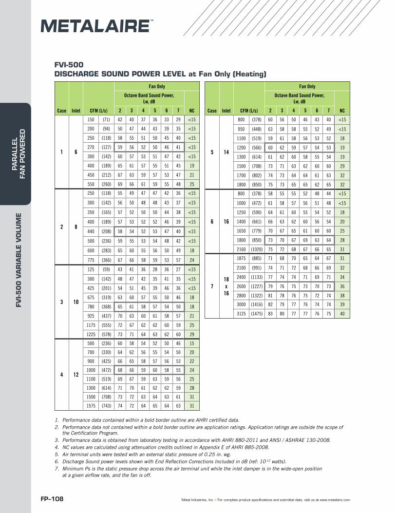
FVI-500DISCHARGE SOUND POWER LEVEL at Fan Only (Heating)
1. Performance data contained within a bold border outline are AHRI certified data.2. Performance data not contained within a bold border outline are application ratings. Application ratings are outside the scope of
the Certification Program.3. Performance data is obtained from laboratory testing in accordance with AHRI 880-2011 and ANSI / ASHRAE 130-2008.4. NC values are calculated using attenuation credits outlined in Appendix E of AHRI 885-2008. 5. Air terminal units were tested with an external static pressure of 0.25 in. wg.6. Discharge Sound power levels shown with End Reflection Corrections Included in dB (ref: 10-12 watts). 7. Minimum Ps is the static pressure drop across the air terminal unit while the inlet damper is in the wide-open position
at a given airflow rate, and the fan is off.
Case Inlet CFM (L/s)
Fan Only
Octave Band Sound Power, Lw, dB
NC2 3 4 5 6 7
1 6
150 (71) 42 40 37 36 33 29 <15
200 (94) 50 47 44 43 39 35 <15
250 (118) 58 55 51 50 45 40 <15
270 (127) 59 56 52 50 46 41 <15
300 (142) 60 57 53 51 47 42 <15
400 (189) 65 61 57 55 51 45 19
450 (212) 67 63 59 57 53 47 21
550 (260) 69 66 61 59 55 48 25
2 8
250 (118) 55 49 47 47 42 36 <15
300 (142) 56 50 48 48 43 37 <15
350 (165) 57 52 50 50 44 38 <15
400 (189) 57 53 52 52 46 39 <15
440 (208) 58 54 52 53 47 40 <15
500 (236) 59 55 53 54 48 42 <15
600 (283) 65 60 55 56 50 49 18
775 (366) 67 66 58 59 53 57 24
3 10
125 (59) 43 41 36 28 36 27 <15
300 (142) 48 47 42 35 41 35 <15
425 (201) 54 51 45 39 46 36 <15
675 (319) 63 60 57 55 50 46 18
780 (368) 65 61 58 57 54 50 18
925 (437) 70 63 60 61 58 57 21
1175 (555) 72 67 62 62 60 59 25
1225 (578) 73 71 64 63 62 60 29
4 12
500 (236) 60 58 54 52 50 46 15
700 (330) 64 62 56 55 54 50 20
900 (425) 66 65 58 57 56 53 22
1000 (472) 68 66 59 60 58 55 24
1100 (519) 69 67 59 63 59 56 25
1300 (614) 71 70 61 62 62 59 28
1500 (708) 73 72 63 64 63 61 31
1575 (743) 74 72 64 65 64 63 31
Case Inlet CFM (L/s)
Fan Only
Octave Band Sound Power, Lw, dB
NC2 3 4 5 6 7
5 14
800 (378) 60 56 50 46 43 40 <15
950 (448) 63 58 58 55 52 49 <15
1100 (519) 59 61 58 56 53 52 18
1200 (566) 60 62 59 57 54 53 19
1300 (614) 61 62 60 58 55 54 19
1500 (708) 73 71 63 62 60 60 29
1700 (802) 74 73 64 64 61 63 32
1800 (850) 75 73 65 65 62 65 32
6 16
800 (378) 58 55 55 52 48 44 <15
1000 (472) 61 58 57 56 51 48 <15
1250 (590) 64 61 60 55 54 52 18
1400 (661) 66 63 62 60 56 54 20
1650 (779) 70 67 65 61 60 60 25
1800 (850) 73 70 67 69 63 64 28
2160 (1020) 75 72 68 67 66 65 31
718x
16
1875 (885) 71 68 70 65 64 67 31
2100 (991) 74 71 72 68 66 69 32
2400 (1133) 77 74 74 71 69 71 34
2600 (1227) 79 76 75 73 70 73 36
2800 (1322) 81 78 76 75 72 74 38
3000 (1416) 82 79 77 76 74 74 39
3125 (1475) 83 80 77 77 76 75 40
FVI-5
00
VA
RIA
BLE
VO
LUM
EPA
RA
LLEL
FA
N P
OW
ERED
FP–109© 2015 Metal Industries, Inc.
FVI-500DISCHARGE SOUND POWER LEVEL at Inlet Ps = 0.25, 0.50 and 0.75 in. wg (Cooling)
1. Performance data contained within a bold border outline are AHRI certified data.2. Performance data not contained within a bold border outline are application ratings. Application ratings are outside the scope of
the Certification Program.3. Performance data is obtained from laboratory testing in accordance with AHRI 880-2011 and ANSI / ASHRAE 130-2008.4. NC values are calculated using attenuation credits outlined in Appendix E of AHRI 885-2008. 5. Air terminal units were tested with an external static pressure of 0.25 in. wg.6. Discharge Sound power levels shown with End Reflection Corrections Included in dB (ref: 10-12 watts). 7. Minimum Ps is the static pressure drop across the air terminal unit while the inlet damper is in the wide-open position
at a given airflow rate, and the fan is off.
Case Inlet CFM (L/s)Min Ps
in. wg (Pa)
Inlet Ps = 0.25 in. wg (62 Pa) Inlet Ps = 0.50 in. wg (125 Pa) Inlet Ps = 0.75 in. wg (187 Pa)
Octave Band Sound Power, Lw, dB
NC
Octave Band Sound Power, Lw, dB
NC
Octave Band Sound Power, Lw, dB
NC2 3 4 5 6 7 2 3 4 5 6 7 2 3 4 5 6 7
1 6
100 (47) 0.080 (20.0) 52 38 33 28 27 26 <15 53 39 33 29 28 27 <15 53 40 33 30 29 26 <15
200 (94) 0.100 (24.9) 54 41 36 31 30 28 <15 53 42 37 32 31 29 <15 54 43 36 33 31 29 <15
250 (118) 0.110 (27.5) 55 43 38 33 31 30 <15 55 45 40 34 34 34 <15 56 45 42 35 38 37 <15
300 (142) 0.127 (31.6) 55 44 39 34 33 31 <15 56 46 42 36 37 34 <15 57 46 43 37 39 38 <15
400 (189) 0.160 (39.7) 57 48 42 37 37 34 <15 58 49 44 38 39 37 <15 59 49 46 40 41 38 <15
450 (212) 0.176 (43.8) 58 49 44 38 38 36 <15 59 51 46 39 40 38 <15 60 50 47 41 42 38 <15
500 (236) 0.192 (47.9) 60 51 46 39 40 37 <15 60 52 47 41 41 38 <15 60 51 47 42 43 39 <15
600 (283) 0.241 (60.1) 63 53 50 45 44 40 <15 63 55 50 45 45 41 <15 64 54 50 46 45 40 16
2 8
200 (94) 0.084 (20.9) 56 42 34 32 29 25 <15 56 43 34 32 29 25 <15 58 43 36 34 31 26 <15
300 (142) 0.094 (23.5) 58 46 39 38 34 30 <15 59 47 40 38 34 30 <15 60 48 41 42 34 29 <15
400 (189) 0.105 (26.2) 60 49 43 42 37 33 <15 61 50 43 41 38 32 <15 62 50 44 45 38 33 <15
500 (236) 0.116 (28.8) 61 51 45 45 40 35 <15 63 53 46 46 42 39 <15 64 54 48 48 44 40 16
650 (307) 0.138 (34.4) 62 55 51 51 45 38 <15 64 56 51 51 45 40 16 66 56 51 52 46 41 18
700 (330) 0.146 (36.3) 62 55 51 51 45 38 <15 64 56 51 51 45 40 16 66 56 51 52 46 41 18
800 (378) 0.161 (40.1) 62 55 51 51 45 38 <15 64 56 51 51 45 40 <15 66 56 51 52 46 41 16
875 (413) 0.175 (43.5) 63 57 54 53 47 40 <15 65 58 54 53 46 42 <15 67 57 54 55 47 42 17
950 (448) 0.188 (46.9) 64 58 55 56 49 42 <15 65 59 56 56 48 43 15 66 59 56 58 49 44 16
1100 (519) 0.227 (56.6) 66 62 57 61 53 46 19 66 62 58 62 51 47 19 67 61 58 64 51 46 18
3 10
300 (142) 0.088 (21.9) 59 48 45 44 34 29 <15 59 51 45 44 37 33 <15 59 52 45 46 39 32 <15
500 (236) 0.103 (25.7) 61 54 47 47 38 30 <15 61 54 48 47 41 35 <15 61 55 48 50 44 35 <15
775 (366) 0.125 (31.1) 66 56 48 48 39 33 16 66 56 50 49 43 42 16 66 60 50 52 48 43 16
925 (437) 0.136 (33.9) 67 58 50 50 40 34 17 67 58 51 51 44 42 17 67 61 51 53 49 44 18
1100 (519) 0.158 (39.3) 67 58 50 50 40 34 17 67 58 51 51 44 42 17 67 61 51 53 49 44 18
1325 (625) 0.190 (47.2) 75 62 53 52 41 35 27 72 60 54 54 47 44 23 67 64 54 57 52 46 21
1450 (684) 0.204 (50.9) 76 64 55 55 41 39 29 73 62 56 56 48 46 25 68 65 56 59 55 47 22
1625 (767) 0.254 (63.2) 78 66 57 56 42 40 31 77 64 58 58 49 47 30 71 66 57 61 56 48 24
1700 (802) 0.270 (67.2) 79 68 59 58 43 41 32 78 66 60 61 50 48 31 72 68 60 63 57 49 26
4 12
450 (212) 0.076 (18.9) 59 52 43 41 37 32 <15 62 55 47 44 40 35 <15 65 58 51 45 39 35 17
650 (307) 0.084 (20.9) 62 54 46 44 40 36 <15 64 57 49 46 43 38 16 67 60 53 48 42 39 20
900 (425) 0.094 (23.4) 65 56 50 47 43 38 <15 67 59 52 49 45 42 17 69 61 55 51 45 42 20
1100 (519) 0.100 (25.0) 67 58 52 50 46 44 17 69 60 54 52 48 44 20 70 62 56 52 48 45 21
1300 (614) 0.107 (26.6) 69 60 54 55 49 47 20 70 62 56 55 50 47 21 72 64 58 56 50 48 23
1500 (708) 0.118 (29.4) 72 61 57 57 53 50 23 73 63 58 57 53 51 25 73 65 60 57 53 51 25
1600 (755) 0.126 (31.5) 73 62 58 58 54 51 25 74 64 60 58 54 52 26 75 66 61 59 54 52 27
1800 (850) 0.143 (35.5) 76 64 61 60 55 53 29 76 65 62 61 56 54 29 77 67 63 62 57 55 30
2200 (1038) 0.182 (45.3) 79 66 64 67 62 61 32 80 67 64 68 62 62 34 80 69 66 66 62 61 34
2500 (1180) 0.212 (52.7) 80 66 65 68 64 63 34 81 67 66 68 65 64 35 81 71 68 69 65 64 35
FVI-5
00
VA
RIA
BLE
VO
LUM
EPA
RA
LLEL FA
N P
OW
ERED
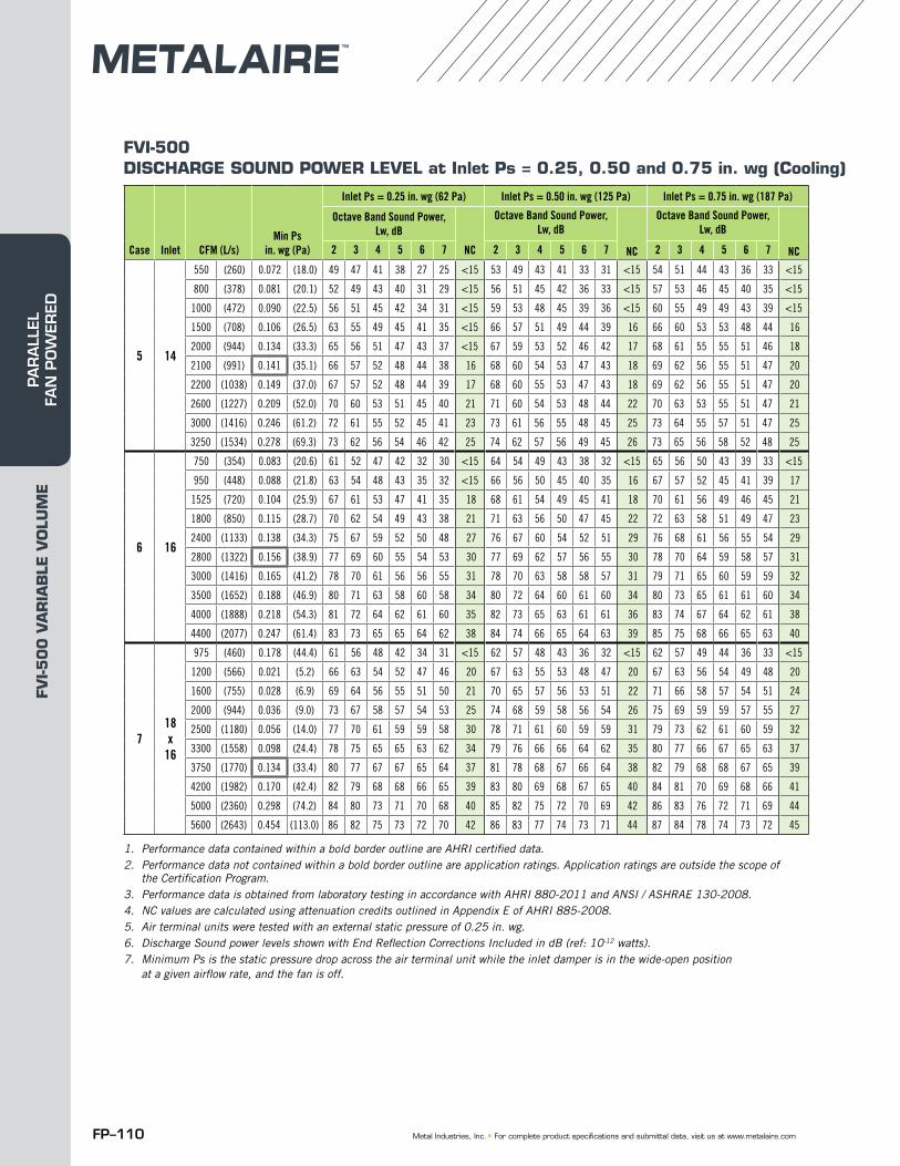
FP–110 Metal Industries, Inc. ■ For complete product specifications and submittal data, visit us at www.metalaire.com
FVI-500DISCHARGE SOUND POWER LEVEL at Inlet Ps = 0.25, 0.50 and 0.75 in. wg (Cooling)
1. Performance data contained within a bold border outline are AHRI certified data.2. Performance data not contained within a bold border outline are application ratings. Application ratings are outside the scope of
the Certification Program.3. Performance data is obtained from laboratory testing in accordance with AHRI 880-2011 and ANSI / ASHRAE 130-2008.4. NC values are calculated using attenuation credits outlined in Appendix E of AHRI 885-2008. 5. Air terminal units were tested with an external static pressure of 0.25 in. wg.6. Discharge Sound power levels shown with End Reflection Corrections Included in dB (ref: 10-12 watts). 7. Minimum Ps is the static pressure drop across the air terminal unit while the inlet damper is in the wide-open position
at a given airflow rate, and the fan is off.
Case Inlet CFM (L/s)Min Ps
in. wg (Pa)
Inlet Ps = 0.25 in. wg (62 Pa) Inlet Ps = 0.50 in. wg (125 Pa) Inlet Ps = 0.75 in. wg (187 Pa)
Octave Band Sound Power, Lw, dB
NC
Octave Band Sound Power, Lw, dB
NC
Octave Band Sound Power, Lw, dB
NC2 3 4 5 6 7 2 3 4 5 6 7 2 3 4 5 6 7
5 14
550 (260) 0.072 (18.0) 49 47 41 38 27 25 <15 53 49 43 41 33 31 <15 54 51 44 43 36 33 <15
800 (378) 0.081 (20.1) 52 49 43 40 31 29 <15 56 51 45 42 36 33 <15 57 53 46 45 40 35 <15
1000 (472) 0.090 (22.5) 56 51 45 42 34 31 <15 59 53 48 45 39 36 <15 60 55 49 49 43 39 <15
1500 (708) 0.106 (26.5) 63 55 49 45 41 35 <15 66 57 51 49 44 39 16 66 60 53 53 48 44 16
2000 (944) 0.134 (33.3) 65 56 51 47 43 37 <15 67 59 53 52 46 42 17 68 61 55 55 51 46 18
2100 (991) 0.141 (35.1) 66 57 52 48 44 38 16 68 60 54 53 47 43 18 69 62 56 55 51 47 20
2200 (1038) 0.149 (37.0) 67 57 52 48 44 39 17 68 60 55 53 47 43 18 69 62 56 55 51 47 20
2600 (1227) 0.209 (52.0) 70 60 53 51 45 40 21 71 60 54 53 48 44 22 70 63 53 55 51 47 21
3000 (1416) 0.246 (61.2) 72 61 55 52 45 41 23 73 61 56 55 48 45 25 73 64 55 57 51 47 25
3250 (1534) 0.278 (69.3) 73 62 56 54 46 42 25 74 62 57 56 49 45 26 73 65 56 58 52 48 25
6 16
750 (354) 0.083 (20.6) 61 52 47 42 32 30 <15 64 54 49 43 38 32 <15 65 56 50 43 39 33 <15
950 (448) 0.088 (21.8) 63 54 48 43 35 32 <15 66 56 50 45 40 35 16 67 57 52 45 41 39 17
1525 (720) 0.104 (25.9) 67 61 53 47 41 35 18 68 61 54 49 45 41 18 70 61 56 49 46 45 21
1800 (850) 0.115 (28.7) 70 62 54 49 43 38 21 71 63 56 50 47 45 22 72 63 58 51 49 47 23
2400 (1133) 0.138 (34.3) 75 67 59 52 50 48 27 76 67 60 54 52 51 29 76 68 61 56 55 54 29
2800 (1322) 0.156 (38.9) 77 69 60 55 54 53 30 77 69 62 57 56 55 30 78 70 64 59 58 57 31
3000 (1416) 0.165 (41.2) 78 70 61 56 56 55 31 78 70 63 58 58 57 31 79 71 65 60 59 59 32
3500 (1652) 0.188 (46.9) 80 71 63 58 60 58 34 80 72 64 60 61 60 34 80 73 65 61 61 60 34
4000 (1888) 0.218 (54.3) 81 72 64 62 61 60 35 82 73 65 63 61 61 36 83 74 67 64 62 61 38
4400 (2077) 0.247 (61.4) 83 73 65 65 64 62 38 84 74 66 65 64 63 39 85 75 68 66 65 63 40
718x
16
975 (460) 0.178 (44.4) 61 56 48 42 34 31 <15 62 57 48 43 36 32 <15 62 57 49 44 36 33 <15
1200 (566) 0.021 (5.2) 66 63 54 52 47 46 20 67 63 55 53 48 47 20 67 63 56 54 49 48 20
1600 (755) 0.028 (6.9) 69 64 56 55 51 50 21 70 65 57 56 53 51 22 71 66 58 57 54 51 24
2000 (944) 0.036 (9.0) 73 67 58 57 54 53 25 74 68 59 58 56 54 26 75 69 59 59 57 55 27
2500 (1180) 0.056 (14.0) 77 70 61 59 59 58 30 78 71 61 60 59 59 31 79 73 62 61 60 59 32
3300 (1558) 0.098 (24.4) 78 75 65 65 63 62 34 79 76 66 66 64 62 35 80 77 66 67 65 63 37
3750 (1770) 0.134 (33.4) 80 77 67 67 65 64 37 81 78 68 67 66 64 38 82 79 68 68 67 65 39
4200 (1982) 0.170 (42.4) 82 79 68 68 66 65 39 83 80 69 68 67 65 40 84 81 70 69 68 66 41
5000 (2360) 0.298 (74.2) 84 80 73 71 70 68 40 85 82 75 72 70 69 42 86 83 76 72 71 69 44
5600 (2643) 0.454 (113.0) 86 82 75 73 72 70 42 86 83 77 74 73 71 44 87 84 78 74 73 72 45
FVI-5
00
VA
RIA
BLE
VO
LUM
EPA
RA
LLEL
FA
N P
OW
ERED
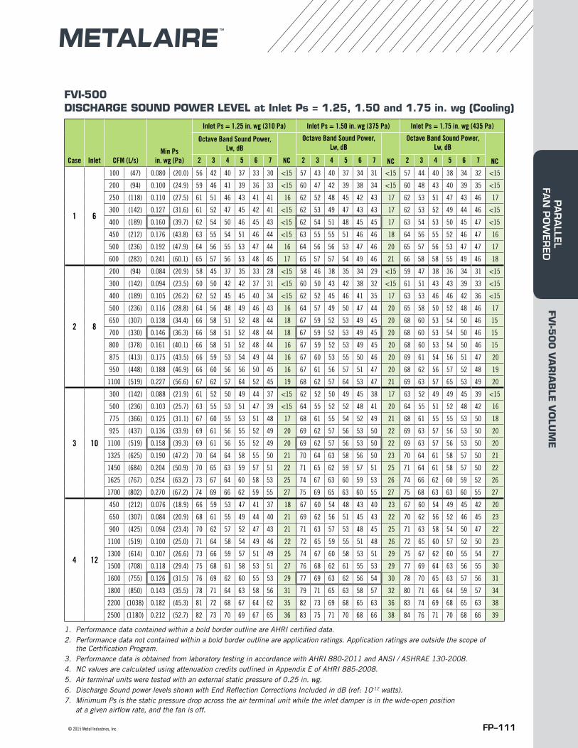
FP–111© 2015 Metal Industries, Inc.
FVI-500DISCHARGE SOUND POWER LEVEL at Inlet Ps = 1.25, 1.50 and 1.75 in. wg (Cooling)
1. Performance data contained within a bold border outline are AHRI certified data.2. Performance data not contained within a bold border outline are application ratings. Application ratings are outside the scope of
the Certification Program.3. Performance data is obtained from laboratory testing in accordance with AHRI 880-2011 and ANSI / ASHRAE 130-2008.4. NC values are calculated using attenuation credits outlined in Appendix E of AHRI 885-2008. 5. Air terminal units were tested with an external static pressure of 0.25 in. wg.6. Discharge Sound power levels shown with End Reflection Corrections Included in dB (ref: 10-12 watts). 7. Minimum Ps is the static pressure drop across the air terminal unit while the inlet damper is in the wide-open position
at a given airflow rate, and the fan is off.
Case Inlet CFM (L/s)Min Ps
in. wg (Pa)
Inlet Ps = 1.25 in. wg (310 Pa) Inlet Ps = 1.50 in. wg (375 Pa) Inlet Ps = 1.75 in. wg (435 Pa)
Octave Band Sound Power, Lw, dB
NC
Octave Band Sound Power, Lw, dB
NC
Octave Band Sound Power, Lw, dB
NC2 3 4 5 6 7 2 3 4 5 6 7 2 3 4 5 6 7
1 6
100 (47) 0.080 (20.0) 56 42 40 37 33 30 <15 57 43 40 37 34 31 <15 57 44 40 38 34 32 <15
200 (94) 0.100 (24.9) 59 46 41 39 36 33 <15 60 47 42 39 38 34 <15 60 48 43 40 39 35 <15
250 (118) 0.110 (27.5) 61 51 46 43 41 41 16 62 52 48 45 42 43 17 62 53 51 47 43 46 17
300 (142) 0.127 (31.6) 61 52 47 45 42 41 <15 62 53 49 47 43 43 17 62 53 52 49 44 46 <15
400 (189) 0.160 (39.7) 62 54 50 46 45 43 <15 62 54 51 48 45 45 17 63 54 53 50 45 47 <15
450 (212) 0.176 (43.8) 63 55 54 51 46 44 <15 63 55 55 51 46 46 18 64 56 55 52 46 47 16
500 (236) 0.192 (47.9) 64 56 55 53 47 44 16 64 56 56 53 47 46 20 65 57 56 53 47 47 17
600 (283) 0.241 (60.1) 65 57 56 53 48 45 17 65 57 57 54 49 46 21 66 58 58 55 49 46 18
2 8
200 (94) 0.084 (20.9) 58 45 37 35 33 28 <15 58 46 38 35 34 29 <15 59 47 38 36 34 31 <15
300 (142) 0.094 (23.5) 60 50 42 42 37 31 <15 60 50 43 42 38 32 <15 61 51 43 43 39 33 <15
400 (189) 0.105 (26.2) 62 52 45 45 40 34 <15 62 52 45 46 41 35 17 63 53 46 46 42 36 <15
500 (236) 0.116 (28.8) 64 56 48 49 46 43 16 64 57 49 50 47 44 20 65 58 50 52 48 46 17
650 (307) 0.138 (34.4) 66 58 51 52 48 44 18 67 59 52 53 49 45 20 68 60 53 54 50 46 15
700 (330) 0.146 (36.3) 66 58 51 52 48 44 18 67 59 52 53 49 45 20 68 60 53 54 50 46 15
800 (378) 0.161 (40.1) 66 58 51 52 48 44 16 67 59 52 53 49 45 20 68 60 53 54 50 46 15
875 (413) 0.175 (43.5) 66 59 53 54 49 44 16 67 60 53 55 50 46 20 69 61 54 56 51 47 20
950 (448) 0.188 (46.9) 66 60 56 56 50 45 16 67 61 56 57 51 47 20 68 62 56 57 52 48 19
1100 (519) 0.227 (56.6) 67 62 57 64 52 45 19 68 62 57 64 53 47 21 69 63 57 65 53 49 20
3 10
300 (142) 0.088 (21.9) 61 52 50 49 44 37 <15 62 52 50 49 45 38 17 63 52 49 49 45 39 <15
500 (236) 0.103 (25.7) 63 55 53 51 47 39 <15 64 55 52 52 48 41 20 64 55 51 52 48 42 16
775 (366) 0.125 (31.1) 67 60 55 53 51 48 17 68 61 55 54 52 49 21 68 61 55 55 53 50 18
925 (437) 0.136 (33.9) 69 61 56 55 52 49 20 69 62 57 56 53 50 22 69 63 57 56 53 50 20
1100 (519) 0.158 (39.3) 69 61 56 55 52 49 20 69 62 57 56 53 50 22 69 63 57 56 53 50 20
1325 (625) 0.190 (47.2) 70 64 64 58 55 50 21 70 64 63 58 56 50 23 70 64 61 58 57 50 21
1450 (684) 0.204 (50.9) 70 65 63 59 57 51 22 71 65 62 59 57 51 25 71 64 61 58 57 50 22
1625 (767) 0.254 (63.2) 73 67 64 60 58 53 25 74 67 63 60 59 53 26 74 66 62 60 59 52 26
1700 (802) 0.270 (67.2) 74 69 66 62 59 55 27 75 69 65 63 60 55 27 75 68 63 63 60 55 27
4 12
450 (212) 0.076 (18.9) 66 59 53 47 41 37 18 67 60 54 48 43 40 23 67 60 54 49 45 42 20
650 (307) 0.084 (20.9) 68 61 55 49 44 40 21 69 62 56 51 45 43 22 70 62 56 52 46 45 23
900 (425) 0.094 (23.4) 70 62 57 52 47 43 21 71 63 57 53 48 45 25 71 63 58 54 50 47 22
1100 (519) 0.100 (25.0) 71 64 58 54 49 46 22 72 65 59 55 51 48 26 72 65 60 57 52 50 23
1300 (614) 0.107 (26.6) 73 66 59 57 51 49 25 74 67 60 58 53 51 29 75 67 62 60 55 54 27
1500 (708) 0.118 (29.4) 75 68 61 58 53 51 27 76 68 62 61 55 53 29 77 69 64 63 56 55 30
1600 (755) 0.126 (31.5) 76 69 62 60 55 53 29 77 69 63 62 56 54 30 78 70 65 63 57 56 31
1800 (850) 0.143 (35.5) 78 71 64 63 58 56 31 79 71 65 63 58 57 32 80 71 66 64 59 57 34
2200 (1038) 0.182 (45.3) 81 72 68 67 64 62 35 82 73 69 68 65 63 36 83 74 69 68 65 63 38
2500 (1180) 0.212 (52.7) 82 73 70 69 67 65 36 83 75 71 70 68 66 38 84 76 71 70 68 66 39
FVI-5
00
VA
RIA
BLE
VO
LUM
EPA
RA
LLEL FA
N P
OW
ERED

FP–112 Metal Industries, Inc. ■ For complete product specifications and submittal data, visit us at www.metalaire.com
FVI-500DISCHARGE SOUND POWER LEVEL at Inlet Ps = 1.25, 1.50 and 1.75 in. wg (Cooling)
1. Performance data contained within a bold border outline are AHRI certified data.2. Performance data not contained within a bold border outline are application ratings. Application ratings are outside the scope of
the Certification Program.3. Performance data is obtained from laboratory testing in accordance with AHRI 880-2011 and ANSI / ASHRAE 130-2008.4. NC values are calculated using attenuation credits outlined in Appendix E of AHRI 885-2008. 5. Air terminal units were tested with an external static pressure of 0.25 in. wg.6. Discharge Sound power levels shown with End Reflection Corrections Included in dB (ref: 10-12 watts). 7. Minimum Ps is the static pressure drop across the air terminal unit while the inlet damper is in the wide-open position
at a given airflow rate, and the fan is off.
Case Inlet CFM (L/s)Min Ps
in. wg (Pa)
Inlet Ps = 1.25 in. wg (310 Pa) Inlet Ps = 1.50 in. wg (375 Pa) Inlet Ps = 1.75 in. wg (435 Pa)
Octave Band Sound Power, Lw, dB
NC
Octave Band Sound Power, Lw, dB
NC
Octave Band Sound Power, Lw, dB
NC2 3 4 5 6 7 2 3 4 5 6 7 2 3 4 5 6 7
5 14
550 (260) 0.072 (18.0) 57 53 46 45 40 37 <15 58 53 49 47 42 37 <15 59 53 51 49 44 37 <15
800 (378) 0.081 (20.1) 60 55 49 47 45 40 <15 61 57 51 50 46 40 <15 61 59 53 52 47 40 15
1000 (472) 0.090 (22.5) 62 60 53 54 48 44 16 64 61 55 56 49 45 19 65 62 57 57 50 45 19
1500 (708) 0.106 (26.5) 69 64 57 57 54 50 21 70 65 59 59 56 51 22 71 65 60 61 57 52 22
2000 (944) 0.134 (33.3) 71 65 58 58 55 51 22 73 66 61 61 57 52 25 74 67 63 63 59 53 26
2100 (991) 0.141 (35.1) 72 66 59 59 56 51 24 73 67 61 61 58 52 25 75 68 64 63 60 53 27
2200 (1038) 0.149 (37.0) 72 66 59 59 56 51 24 74 67 62 61 58 52 26 75 68 64 63 60 53 27
2600 (1227) 0.209 (52.0) 72 67 60 60 57 52 25 74 68 63 62 59 53 26 75 69 65 64 61 54 27
3000 (1416) 0.246 (61.2) 74 68 61 61 57 52 26 76 69 64 63 59 53 29 77 70 66 65 61 54 30
3250 (1534) 0.278 (69.3) 74 68 62 62 58 53 26 76 69 65 64 60 54 29 77 70 67 66 62 55 30
6 16
750 (354) 0.083 (20.6) 66 57 51 45 41 40 16 67 58 52 51 42 41 20 67 59 53 57 43 42 17
950 (448) 0.088 (21.8) 68 59 54 47 43 42 18 69 60 55 49 44 43 22 69 60 56 50 45 44 20
1525 (720) 0.104 (25.9) 71 62 57 50 47 46 22 72 63 58 52 49 48 23 72 63 59 53 51 50 23
1800 (850) 0.115 (28.7) 73 65 59 53 52 51 25 74 66 61 55 53 52 26 74 67 63 57 53 52 26
2400 (1133) 0.138 (34.3) 78 69 62 58 57 56 31 79 70 64 59 58 57 32 80 71 66 60 58 57 34
2800 (1322) 0.156 (38.9) 79 73 67 63 61 59 32 80 74 68 63 61 60 34 81 76 69 63 61 60 35
3000 (1416) 0.165 (41.2) 80 75 69 65 63 61 34 81 77 70 65 63 61 37 82 78 70 64 62 61 38
3500 (1652) 0.188 (46.9) 81 76 70 65 65 62 35 83 78 71 66 66 63 38 84 79 72 67 66 63 39
4000 (1888) 0.218 (54.3) 84 77 71 67 66 63 39 86 80 72 68 67 64 41 87 82 73 68 67 64 43
4400 (2077) 0.247 (61.4) 86 78 72 68 67 65 41 87 81 73 69 68 66 43 88 83 74 69 68 66 44
718x
16
975 (460) 0.178 (44.4) 64 58 50 48 41 35 <15 64 58 50 48 41 35 16 64 58 50 48 41 35 <15
1200 (566) 0.021 (5.2) 68 64 57 56 51 49 21 68 64 57 56 51 49 22 68 64 57 56 51 49 21
1600 (755) 0.028 (6.9) 72 67 59 58 56 52 25 72 67 59 58 56 52 25 72 67 59 58 56 52 25
2000 (944) 0.036 (9.0) 77 72 61 60 58 57 31 77 72 61 60 58 57 31 77 72 61 60 58 57 31
2500 (1180) 0.056 (14.0) 80 75 63 61 60 59 34 80 75 63 61 60 59 34 80 75 63 61 60 59 34
3300 (1558) 0.098 (24.4) 83 80 75 73 71 70 40 83 80 75 73 71 70 40 83 80 75 73 71 70 40
3750 (1770) 0.134 (33.4) 85 82 77 76 74 74 42 85 82 77 76 74 74 42 85 82 77 76 74 74 42
4200 (1982) 0.170 (42.4) 86 83 78 78 77 77 44 86 83 78 78 77 77 44 86 83 78 78 77 77 44
5000 (2360) 0.298 (74.2) 87 84 81 79 78 77 45 87 84 81 79 78 77 45 87 84 81 79 78 77 45
5600 (2643) 0.454 (113.0) 88 85 82 80 79 78 46 88 85 82 80 79 78 46 88 85 82 80 79 78 46
FVI-5
00
VA
RIA
BLE
VO
LUM
EPA
RA
LLEL
FA
N P
OW
ERED
FP–113© 2015 Metal Industries, Inc.
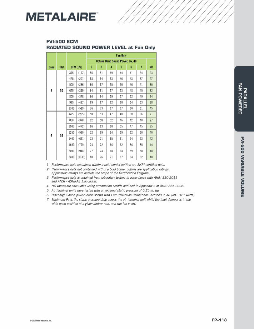
FVI-500 ECMRADIATED SOUND POWER LEVEL at Fan Only
1. Performance data contained within a bold border outline are AHRI certified data.2. Performance data not contained within a bold border outline are application ratings.
Application ratings are outside the scope of the Certification Program.3. Performance data is obtained from laboratory testing in accordance with AHRI 880-2011
and ANSI / ASHRAE 130-2008.4. NC values are calculated using attenuation credits outlined in Appendix E of AHRI 885-2008. 5. Air terminal units were tested with an external static pressure of 0.25 in. wg.6. Discharge Sound power levels shown with End Reflection Corrections Included in dB (ref: 10-12 watts). 7. Minimum Ps is the static pressure drop across the air terminal unit while the inlet damper is in the
wide-open position at a given airflow rate, and the fan is off.
Case Inlet CFM (L/s)
Fan Only
Octave Band Sound Power, Lw, dB
NC2 3 4 5 6 7
3 10
375 (177) 55 51 49 44 41 34 23
425 (201) 58 54 53 46 43 37 27
500 (236) 60 57 55 50 46 41 30
675 (319) 64 61 57 53 48 45 32
800 (378) 66 64 59 57 52 49 34
925 (437) 69 67 62 60 54 53 38
1100 (519) 76 73 67 67 60 61 45
6 16
625 (295) 58 53 47 40 38 36 21
800 (378) 62 58 52 46 42 40 27
1000 (472) 66 63 60 55 47 45 35
1250 (590) 72 69 64 59 52 50 40
1400 (661) 73 71 65 61 54 53 42
1650 (779) 74 72 66 62 56 55 44
2000 (944) 77 74 68 64 59 58 48
2400 (1133) 80 76 71 67 64 62 48
FVI-5
00
VA
RIA
BLE
VO
LUM
EPA
RA
LLEL FA
N P
OW
ERED

FP–114 Metal Industries, Inc. ■ For complete product specifications and submittal data, visit us at www.metalaire.com
FVI-500 ECMRADIATED SOUND POWER LEVEL at Inlet Ps = 0.25, 0.50, 0.75, 1.25 and 1.75 in. wg
1. Performance data contained within a bold border outline are AHRI certified data.2. Performance data not contained within a bold border outline are application ratings. Application ratings are outside the scope of
the Certification Program.3. Performance data is obtained from laboratory testing in accordance with AHRI 880-2011 and ANSI / ASHRAE 130-2008.4. NC values are calculated using attenuation credits outlined in Appendix E of AHRI 885-2008. 5. Air terminal units were tested with an external static pressure of 0.25 in. wg.6. Discharge Sound power levels shown with End Reflection Corrections Included in dB (ref: 10-12 watts). 7. Minimum Ps is the static pressure drop across the air terminal unit while the inlet damper is in the wide-open position
at a given airflow rate, and the fan is off.
Case Inlet CFM (L/s)Min Ps
in. wg (Pa)
Inlet Ps = 0.25 in. wg (62 Pa) Inlet Ps = 0.50 in. wg (125 Pa) Inlet Ps = 0.75 in. wg (187 Pa)
Octave Band Sound Power, Lw, dB
NC
Octave Band Sound Power, Lw, dB
NC
Octave Band Sound Power, Lw, dB
NC2 3 4 5 6 7 2 3 4 5 6 7 2 3 4 5 6 7
3 10
300 (142) 0.088 (21.9) 52 49 44 40 31 24 18 53 49 45 41 32 25 19 55 50 46 42 33 27 20
500 (236) 0.103 (25.7) 54 51 46 42 34 25 20 56 52 47 43 35 27 21 57 53 49 45 37 29 23
775 (366) 0.125 (31.1) 56 53 47 43 35 27 21 59 55 49 45 37 32 24 62 58 51 47 40 36 27
925 (437) 0.136 (33.9) 57 55 49 45 36 28 24 60 57 50 47 38 32 26 63 59 53 48 41 37 28
1075 (507) 0.158 (39.3) 58 57 52 48 36 28 26 60 59 52 48 39 34 28 65 61 54 49 42 37 31
1325 (625) 0.190 (47.2) 65 61 55 50 37 29 31 65 61 56 51 41 36 31 65 64 57 53 45 38 34
1450 (684) 0.204 (50.9) 66 63 57 53 37 32 33 66 63 58 53 42 37 33 66 65 59 55 47 39 35
1625 (767) 0.254 (63.2) 68 65 59 54 38 33 35 69 65 60 55 43 38 35 69 66 60 56 48 40 37
1700 (802) 0.270 (67.2) 69 67 61 56 39 34 38 70 67 62 57 44 39 38 70 68 63 58 49 41 39
6 16
750 (354) 0.083 (20.6) 49 44 35 30 26 24 <15 51 46 37 33 29 28 <15 53 48 39 36 32 31 15
950 (448) 0.088 (21.8) 52 45 37 33 29 26 <15 54 47 39 35 32 30 <15 56 50 42 38 35 32 18
1525 (720) 0.104 (25.9) 57 47 40 36 32 28 18 59 49 42 38 35 32 21 61 53 47 42 38 33 23
1800 (850) 0.115 (28.7) 60 48 44 42 37 30 22 62 54 48 47 41 36 25 64 59 53 49 45 41 28
2400 (1133) 0.138 (34.3) 65 58 52 48 43 37 29 67 60 54 49 45 40 31 68 62 56 51 47 42 32
3000 (1416) 0.165 (41.2) 69 63 57 51 47 41 34 70 64 57 52 48 43 35 71 65 58 53 49 44 36
3500 (1652) 0.188 (46.9) 73 66 60 55 49 45 39 74 67 61 56 50 46 40 74 68 62 57 52 47 40
4000 (1888) 0.218 (54.3) 75 68 62 57 51 47 41 75 69 63 58 52 49 41 76 69 64 59 53 50 43
4400 (2077) 0.247 (61.4) 77 71 65 59 53 49 44 78 72 65 59 54 51 45 78 72 66 60 56 52 45
Case Inlet CFM (L/s)Min Ps in. wg
(Pa)
Inlet Ps = 1.25 in. wg (310 Pa) Inlet Ps = 1.75 in. wg (435 Pa)
Octave Band Sound Power, Lw, dB
NC
Octave Band Sound Power, Lw, dB
NC2 3 4 5 6 7 2 3 4 5 6 7
3 10
300 (142) 0.088 (21.9) 57 51 47 45 36 30 21 59 53 49 46 38 33 23
500 (236) 0.103 (25.7) 59 54 50 47 39 32 24 60 56 51 49 41 35 25
775 (366) 0.125 (31.1) 63 59 52 49 42 39 28 64 62 55 52 45 42 32
925 (437) 0.136 (33.9) 65 60 53 51 43 40 29 65 64 57 53 45 42 34
1075 (507) 0.158 (39.3) 66 60 54 52 45 41 30 66 65 59 54 46 43 35
1325 (625) 0.190 (47.2) 67 64 62 55 48 42 37 67 65 62 55 48 43 37
1450 (684) 0.204 (50.9) 67 65 61 56 49 43 36 68 66 63 56 49 43 38
1625 (767) 0.254 (63.2) 70 67 62 57 50 44 38 71 68 64 58 51 45 39
1700 (802) 0.270 (67.2) 71 69 64 59 51 46 40 72 70 65 61 52 47 41
6 16
750 (354) 0.083 (20.6) 56 50 43 39 35 33 18 58 52 46 42 37 35 20
950 (448) 0.088 (21.8) 58 52 50 42 37 39 24 60 56 52 48 45 43 26
1525 (720) 0.104 (25.9) 64 56 53 46 44 43 27 66 62 57 50 49 48 32
1800 (850) 0.115 (28.7) 67 62 57 53 49 46 32 68 65 60 58 55 51 35
2400 (1133) 0.138 (34.3) 70 64 59 54 50 47 35 72 67 62 59 55 51 38
3000 (1416) 0.165 (41.2) 73 67 61 56 51 47 39 75 69 64 60 57 53 41
3500 (1652) 0.188 (46.9) 76 69 64 59 53 49 43 78 71 66 61 58 54 45
4000 (1888) 0.218 (54.3) 78 71 66 61 55 52 45 81 73 68 63 59 57 49
4400 (2077) 0.247 (61.4) 80 73 68 62 58 54 48 83 75 70 65 62 60 52
FVI-5
00
VA
RIA
BLE
VO
LUM
EPA
RA
LLEL
FA
N P
OW
ERED
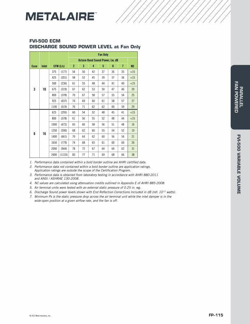
FP–115© 2015 Metal Industries, Inc.
FVI-500 ECMDISCHARGE SOUND POWER LEVEL at Fan Only
1. Performance data contained within a bold border outline are AHRI certified data.2. Performance data not contained within a bold border outline are application ratings.
Application ratings are outside the scope of the Certification Program.3. Performance data is obtained from laboratory testing in accordance with AHRI 880-2011
and ANSI / ASHRAE 130-2008.4. NC values are calculated using attenuation credits outlined in Appendix E of AHRI 885-2008. 5. Air terminal units were tested with an external static pressure of 0.25 in. wg.6. Discharge Sound power levels shown with End Reflection Corrections Included in dB (ref: 10-12 watts). 7. Minimum Ps is the static pressure drop across the air terminal unit while the inlet damper is in the
wide-open position at a given airflow rate, and the fan is off.
Case Inlet CFM (L/s)
Fan Only
Octave Band Sound Power, Lw, dB
NC2 3 4 5 6 7
3 10
375 (177) 54 50 42 37 36 35 <15
425 (201) 58 52 45 39 37 36 <15
500 (236) 61 55 48 44 41 40 <15
675 (319) 67 62 53 50 47 46 20
800 (378) 70 67 58 57 55 54 25
925 (437) 74 69 60 61 58 57 27
1100 (519) 76 71 62 62 60 59 29
6 16
625 (295) 60 54 52 48 45 41 <15
800 (378) 61 56 55 52 48 44 <15
1000 (472) 65 60 58 56 51 48 16
1250 (590) 68 62 60 55 54 52 19
1400 (661) 70 64 62 60 56 54 21
1650 (779) 74 68 65 61 60 60 26
2000 (944) 78 72 67 64 64 62 31
2400 (1133) 83 77 71 69 68 66 38
FVI-5
00
VA
RIA
BLE
VO
LUM
EPA
RA
LLEL FA
N P
OW
ERED
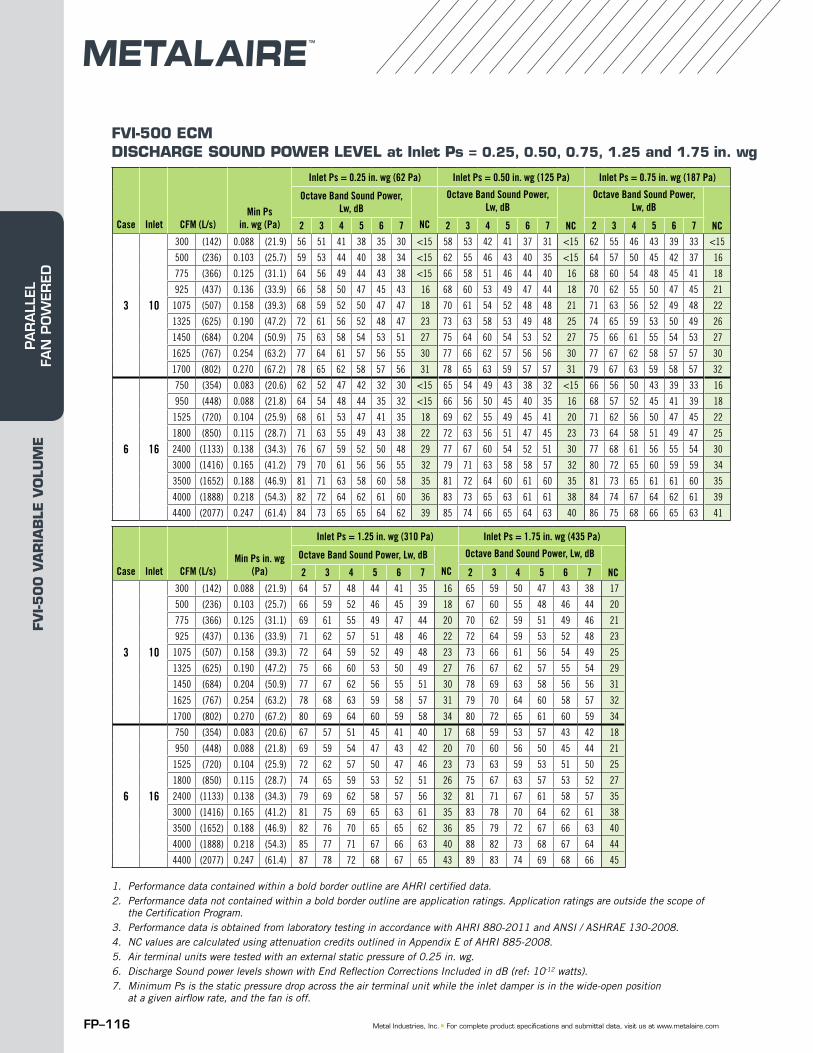
FP–116 Metal Industries, Inc. ■ For complete product specifications and submittal data, visit us at www.metalaire.com
FVI-500 ECMDISCHARGE SOUND POWER LEVEL at Inlet Ps = 0.25, 0.50, 0.75, 1.25 and 1.75 in. wg
1. Performance data contained within a bold border outline are AHRI certified data.2. Performance data not contained within a bold border outline are application ratings. Application ratings are outside the scope of
the Certification Program.3. Performance data is obtained from laboratory testing in accordance with AHRI 880-2011 and ANSI / ASHRAE 130-2008.4. NC values are calculated using attenuation credits outlined in Appendix E of AHRI 885-2008. 5. Air terminal units were tested with an external static pressure of 0.25 in. wg.6. Discharge Sound power levels shown with End Reflection Corrections Included in dB (ref: 10-12 watts). 7. Minimum Ps is the static pressure drop across the air terminal unit while the inlet damper is in the wide-open position
at a given airflow rate, and the fan is off.
Case Inlet CFM (L/s)Min Ps
in. wg (Pa)
Inlet Ps = 0.25 in. wg (62 Pa) Inlet Ps = 0.50 in. wg (125 Pa) Inlet Ps = 0.75 in. wg (187 Pa)
Octave Band Sound Power, Lw, dB
NC
Octave Band Sound Power, Lw, dB
NC
Octave Band Sound Power, Lw, dB
NC2 3 4 5 6 7 2 3 4 5 6 7 2 3 4 5 6 7
3 10
300 (142) 0.088 (21.9) 56 51 41 38 35 30 <15 58 53 42 41 37 31 <15 62 55 46 43 39 33 <15
500 (236) 0.103 (25.7) 59 53 44 40 38 34 <15 62 55 46 43 40 35 <15 64 57 50 45 42 37 16
775 (366) 0.125 (31.1) 64 56 49 44 43 38 <15 66 58 51 46 44 40 16 68 60 54 48 45 41 18
925 (437) 0.136 (33.9) 66 58 50 47 45 43 16 68 60 53 49 47 44 18 70 62 55 50 47 45 21
1075 (507) 0.158 (39.3) 68 59 52 50 47 47 18 70 61 54 52 48 48 21 71 63 56 52 49 48 22
1325 (625) 0.190 (47.2) 72 61 56 52 48 47 23 73 63 58 53 49 48 25 74 65 59 53 50 49 26
1450 (684) 0.204 (50.9) 75 63 58 54 53 51 27 75 64 60 54 53 52 27 75 66 61 55 54 53 27
1625 (767) 0.254 (63.2) 77 64 61 57 56 55 30 77 66 62 57 56 56 30 77 67 62 58 57 57 30
1700 (802) 0.270 (67.2) 78 65 62 58 57 56 31 78 65 63 59 57 57 31 79 67 63 59 58 57 32
6 16
750 (354) 0.083 (20.6) 62 52 47 42 32 30 <15 65 54 49 43 38 32 <15 66 56 50 43 39 33 16
950 (448) 0.088 (21.8) 64 54 48 44 35 32 <15 66 56 50 45 40 35 16 68 57 52 45 41 39 18
1525 (720) 0.104 (25.9) 68 61 53 47 41 35 18 69 62 55 49 45 41 20 71 62 56 50 47 45 22
1800 (850) 0.115 (28.7) 71 63 55 49 43 38 22 72 63 56 51 47 45 23 73 64 58 51 49 47 25
2400 (1133) 0.138 (34.3) 76 67 59 52 50 48 29 77 67 60 54 52 51 30 77 68 61 56 55 54 30
3000 (1416) 0.165 (41.2) 79 70 61 56 56 55 32 79 71 63 58 58 57 32 80 72 65 60 59 59 34
3500 (1652) 0.188 (46.9) 81 71 63 58 60 58 35 81 72 64 60 61 60 35 81 73 65 61 61 60 35
4000 (1888) 0.218 (54.3) 82 72 64 62 61 60 36 83 73 65 63 61 61 38 84 74 67 64 62 61 39
4400 (2077) 0.247 (61.4) 84 73 65 65 64 62 39 85 74 66 65 64 63 40 86 75 68 66 65 63 41
Case Inlet CFM (L/s)Min Ps in. wg
(Pa)
Inlet Ps = 1.25 in. wg (310 Pa) Inlet Ps = 1.75 in. wg (435 Pa)
Octave Band Sound Power, Lw, dB
NC
Octave Band Sound Power, Lw, dB
NC2 3 4 5 6 7 2 3 4 5 6 7
3 10
300 (142) 0.088 (21.9) 64 57 48 44 41 35 16 65 59 50 47 43 38 17
500 (236) 0.103 (25.7) 66 59 52 46 45 39 18 67 60 55 48 46 44 20
775 (366) 0.125 (31.1) 69 61 55 49 47 44 20 70 62 59 51 49 46 21
925 (437) 0.136 (33.9) 71 62 57 51 48 46 22 72 64 59 53 52 48 23
1075 (507) 0.158 (39.3) 72 64 59 52 49 48 23 73 66 61 56 54 49 25
1325 (625) 0.190 (47.2) 75 66 60 53 50 49 27 76 67 62 57 55 54 29
1450 (684) 0.204 (50.9) 77 67 62 56 55 51 30 78 69 63 58 56 56 31
1625 (767) 0.254 (63.2) 78 68 63 59 58 57 31 79 70 64 60 58 57 32
1700 (802) 0.270 (67.2) 80 69 64 60 59 58 34 80 72 65 61 60 59 34
6 16
750 (354) 0.083 (20.6) 67 57 51 45 41 40 17 68 59 53 57 43 42 18
950 (448) 0.088 (21.8) 69 59 54 47 43 42 20 70 60 56 50 45 44 21
1525 (720) 0.104 (25.9) 72 62 57 50 47 46 23 73 63 59 53 51 50 25
1800 (850) 0.115 (28.7) 74 65 59 53 52 51 26 75 67 63 57 53 52 27
2400 (1133) 0.138 (34.3) 79 69 62 58 57 56 32 81 71 67 61 58 57 35
3000 (1416) 0.165 (41.2) 81 75 69 65 63 61 35 83 78 70 64 62 61 38
3500 (1652) 0.188 (46.9) 82 76 70 65 65 62 36 85 79 72 67 66 63 40
4000 (1888) 0.218 (54.3) 85 77 71 67 66 63 40 88 82 73 68 67 64 44
4400 (2077) 0.247 (61.4) 87 78 72 68 67 65 43 89 83 74 69 68 66 45
FVI-5
00
VA
RIA
BLE
VO
LUM
EPA
RA
LLEL
FA
N P
OW
ERED
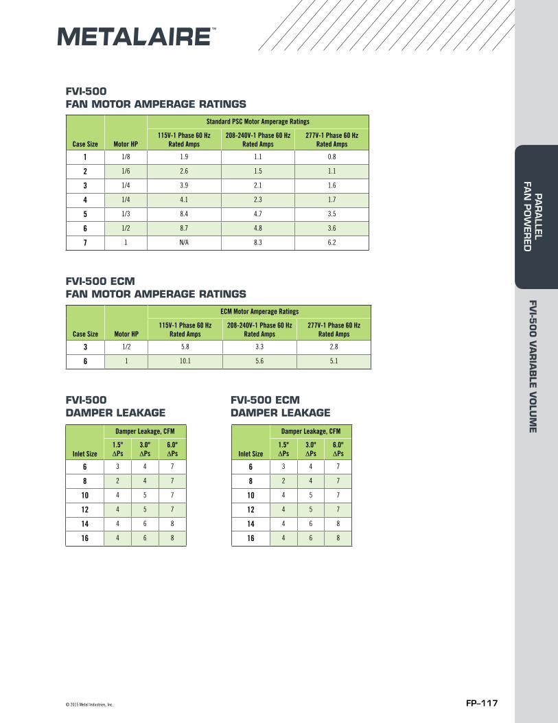
FP–117© 2015 Metal Industries, Inc.
FVI-500 FAN MOTOR AMPERAGE RATINGS
FVI-500 DAMPER LEAKAGE
FVI-500 ECM DAMPER LEAKAGE
Case Size Motor HP
Standard PSC Motor Amperage Ratings
115V-1 Phase 60 Hz Rated Amps
208-240V-1 Phase 60 Hz Rated Amps
277V-1 Phase 60 Hz Rated Amps
1 1/8 1.9 1.1 0.8
2 1/6 2.6 1.5 1.1
3 1/4 3.9 2.1 1.6
4 1/4 4.1 2.3 1.7
5 1/3 8.4 4.7 3.5
6 1/2 8.7 4.8 3.6
7 1 N/A 8.3 6.2
FVI-500 ECM FAN MOTOR AMPERAGE RATINGS
Case Size Motor HP
ECM Motor Amperage Ratings
115V-1 Phase 60 Hz Rated Amps
208-240V-1 Phase 60 Hz Rated Amps
277V-1 Phase 60 Hz Rated Amps
3 1/2 5.8 3.3 2.8
6 1 10.1 5.6 5.1
Inlet Size
Damper Leakage, CFM
1.5" ΔPs
3.0" ΔPs
6.0" ΔPs
6 3 4 7
8 2 4 7
10 4 5 7
12 4 5 7
14 4 6 8
16 4 6 8
Inlet Size
Damper Leakage, CFM
1.5" ΔPs
3.0" ΔPs
6.0" ΔPs
6 3 4 7
8 2 4 7
10 4 5 7
12 4 5 7
14 4 6 8
16 4 6 8
FVI-5
00
VA
RIA
BLE
VO
LUM
EPA
RA
LLEL FA
N P
OW
ERED
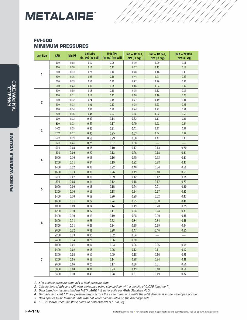
FP–118 Metal Industries, Inc. ■ For complete product specifications and submittal data, visit us at www.metalaire.com
FVI-500 MINIMUM PRESSURES
1. ΔPs = static pressure drop; ΔPt = total pressure drop.2. Calculations of ΔPs and ΔPt were performed using standard air with a density of 0.075 lbm / cu.ft.3. Data based on testing standard METALAIRE hot water coils per AHRI Standard 410.4. Unit ΔPs and Unit ΔPt are pressure drops across the air terminal unit while the inlet damper is in the wide-open position5. Data applies to air terminal units with hot water coil mounted on the discharge side.6. ‘ —’ is shown when the static pressure drop exceeds 0.50 in. wg.
Unit Size CFM Min PS Unit ΔPs(in. wg) [no coil]
Unit ΔPs(in. wg) [no coil]
Unit + 1R Coil, ΔPs (in. wg)
Unit + 1R Coil, ΔPs (in. wg)
Unit + 2R Coil, ΔPt (in. wg)
1
100 0.08 0.10 0.08 0.10 0.09 0.11
200 0.10 0.16 0.11 0.17 0.12 0.18
300 0.13 0.27 0.14 0.28 0.16 0.30
400 0.16 0.42 0.18 0.44 0.21 0.47
500 0.19 0.59 0.22 0.62 0.26 0.66
600 0.24 0.82 0.28 0.86 0.34 0.92
2
300 0.09 0.14 0.10 0.15 0.12 0.17
400 0.11 0.18 0.13 0.20 0.16 0.23
500 0.12 0.24 0.15 0.27 0.19 0.31
600 0.13 0.31 0.17 0.35 0.23 0.41
700 0.14 0.38 0.20 0.44 0.27 0.51
800 0.16 0.47 0.23 0.54 0.32 0.63
3
600 0.12 0.30 0.14 0.32 0.17 0.35
800 0.13 0.45 0.17 0.49 0.22 0.54
1000 0.15 0.35 0.21 0.41 0.27 0.47
1200 0.17 0.45 0.25 0.53 0.34 0.62
1400 0.19 0.58 0.29 0.68 0.41 0.80
1600 0.24 0.75 0.37 0.88 — —
4
600 0.08 0.15 0.10 0.17 0.13 0.20
800 0.09 0.22 0.13 0.26 0.18 0.31
1000 0.10 0.19 0.16 0.25 0.22 0.31
1200 0.11 0.24 0.19 0.32 0.28 0.41
1400 0.12 0.30 0.22 0.40 0.34 0.52
1600 0.13 0.36 0.26 0.49 0.40 0.63
5
600 0.07 0.10 0.09 0.12 0.12 0.15
800 0.08 0.14 0.12 0.18 0.17 0.23
1000 0.09 0.18 0.15 0.24 0.21 0.30
1200 0.10 0.16 0.18 0.24 0.27 0.33
1400 0.10 0.19 0.20 0.29 0.32 0.41
1600 0.11 0.22 0.24 0.35 0.38 0.49
6
1000 0.09 0.14 0.14 0.19 0.20 0.25
1200 0.10 0.17 0.17 0.24 0.24 0.31
1400 0.10 0.19 0.19 0.28 0.29 0.38
1600 0.11 0.23 0.22 0.34 0.34 0.46
1800 0.11 0.26 0.24 0.39 0.39 0.54
2000 0.12 0.31 0.28 0.47 0.46 0.65
2200 0.13 0.35 0.32 0.54 — —
2400 0.14 0.28 0.36 0.50 — —
7
1000 0.01 0.04 0.03 0.06 0.06 0.09
1400 0.02 0.08 0.06 0.12 0.11 0.17
1800 0.03 0.12 0.09 0.18 0.16 0.25
2200 0.05 0.19 0.14 0.28 0.24 0.38
2600 0.06 0.25 0.17 0.36 0.31 0.50
3000 0.08 0.34 0.23 0.49 0.40 0.66
3400 0.10 0.43 0.28 0.61 0.49 0.82
FVI-5
00
VA
RIA
BLE
VO
LUM
EPA
RA
LLEL
FA
N P
OW
ERED
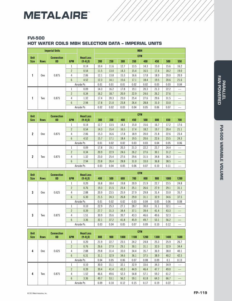
FP–119© 2015 Metal Industries, Inc.
FVI-500 HOT WATER COILS MBH SELECTION DATA – IMPERIAL UNITS
Imperial Units
Head Loss (ft-H2O)
MBH
Unit Size Rows
Connection OD GPM
CFM
200 250 300 350 400 450 500 550
1 One 0.875
1 0.14 10.4 11.6 12.7 13.5 14.3 15.0 15.6 16.2
2 0.54 11.5 13.0 14.3 15.4 16.5 17.4 18.2 19.0
4 2.06 12.1 13.8 15.3 16.6 17.8 18.9 20.0 20.9
6 4.52 12.3 14.1 15.6 17.1 18.4 19.5 20.6 21.6
Airside Ps 0.01 0.01 0.01 0.02 0.02 0.03 0.03 0.04
1 Two 0.875
1 0.09 14.3 16.2 17.8 19.1 20.3 21.3 22.2 —
2 0.34 16.2 18.7 20.9 22.9 24.6 26.2 27.6 —
4 1.32 17.4 20.3 23.0 25.4 27.6 29.6 31.5 —
6 2.94 17.8 21.0 23.8 26.4 28.8 31.0 33.0 —
Airside Ps 0.02 0.02 0.03 0.04 0.05 0.06 0.07 —
Unit Size Rows
Connection OD GPM
Head Loss (ft-H2O)
CFM
300 350 400 450 500 600 650 700
2 One 0.875
1 0.14 12.7 13.5 14.3 15.0 15.6 16.7 17.2 17.6
2 0.54 14.3 15.4 16.5 17.4 18.2 19.7 20.4 21.1
4 2.06 15.3 16.6 17.8 18.9 20.0 21.8 22.6 23.4
6 4.52 15.7 17.1 18.4 19.5 20.6 22.6 23.5 24.3
Airside Ps 0.01 0.02 0.02 0.03 0.03 0.04 0.05 0.06
2 Two 0.875
1 0.09 17.8 19.1 20.3 21.3 22.2 23.7 24.4 —
2 0.34 20.9 22.9 24.6 26.2 27.6 30.1 31.2 —
4 1.32 23.0 25.4 27.6 29.6 31.5 34.8 36.3 —
6 2.94 23.8 26.4 28.8 31.0 33.0 36.8 38.5 —
Airside Ps 0.03 0.04 0.05 0.06 0.07 0.10 0.11 —
Unit Size Rows
Connection OD GPM
Head Loss (ft-H2O)
CFM
400 500 600 700 800 900 1000 1200
3 One 0.625
1 0.20 16.8 18.4 19.8 20.9 21.9 22.7 23.5 24.8
2 0.76 19.3 21.5 23.4 25.1 26.6 27.9 29.1 31.1
4 2.88 20.9 23.5 25.9 27.9 29.8 31.4 33.0 35.7
6 6.30 21.5 24.3 26.8 29.0 31.1 32.9 34.6 37.5
Airside Ps 0.01 0.02 0.02 0.03 0.04 0.05 0.06 0.08
3 Two 0.875
1 0.10 22.9 25.3 27.1 28.7 30.0 31.1 32.1 —
2 0.39 27.7 31.3 34.4 37.1 39.4 41.4 43.3 —
4 1.51 30.9 35.6 39.7 43.3 46.6 49.6 52.3 —
6 3.36 32.1 37.2 41.8 45.9 49.7 53.1 56.2 —
Airside Ps 0.03 0.04 0.05 0.07 0.09 0.10 0.12 —
Unit Size Rows
Connection OD GPM
Head Loss (ft-H2O)
CFM
800 900 1000 1100 1200 1300 1400 1600
4 One 0.625
1 0.20 21.9 22.7 23.5 24.2 24.8 25.3 25.9 26.7
2 0.76 26.6 27.9 29.1 30.1 31.1 32.0 32.9 34.4
4 2.88 29.8 31.4 33.0 34.4 35.7 36.9 38.0 40.1
6 6.31 31.1 32.9 34.6 36.1 37.5 38.9 40.2 42.5
Airside Ps 0.04 0.05 0.06 0.07 0.08 0.09 0.1 0.13
4 Two 0.875
1 0.10 30.0 31.1 32.1 32.9 33.6 34.3 34.9 —
2 0.39 39.4 41.4 43.3 44.9 46.4 47.7 49.0 —
4 1.52 46.6 49.6 52.3 54.8 57.1 59.2 61.2 —
6 3.36 49.7 53.1 56.2 59.1 61.8 64.3 66.7 —
Airside Ps 0.09 0.10 0.12 0.15 0.17 0.19 0.22 —
FVI-5
00
VA
RIA
BLE
VO
LUM
EPA
RA
LLEL FA
N P
OW
ERED
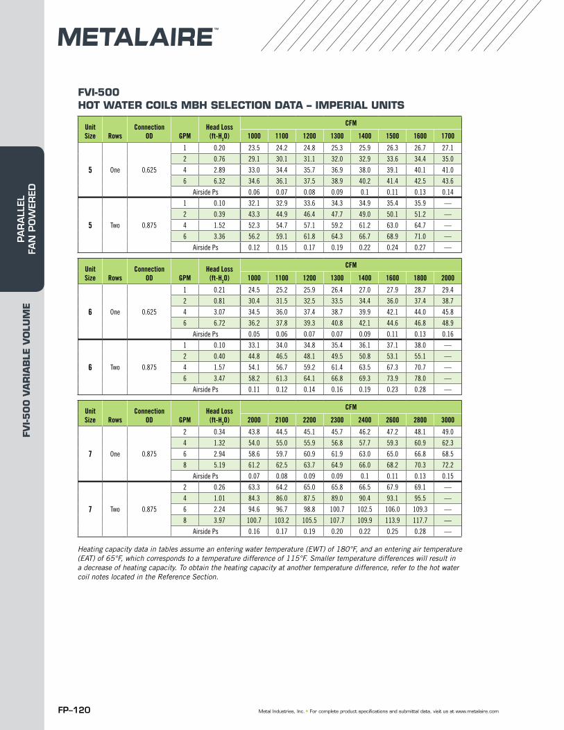
FP–120 Metal Industries, Inc. ■ For complete product specifications and submittal data, visit us at www.metalaire.com
Heating capacity data in tables assume an entering water temperature (EWT) of 180°F, and an entering air temperature (EAT) of 65°F, which corresponds to a temperature difference of 115°F. Smaller temperature differences will result in a decrease of heating capacity. To obtain the heating capacity at another temperature difference, refer to the hot water coil notes located in the Reference Section.
Unit Size Rows
Connection OD GPM
Head Loss (ft-H2O)
CFM
1000 1100 1200 1300 1400 1500 1600 1700
5 One 0.625
1 0.20 23.5 24.2 24.8 25.3 25.9 26.3 26.7 27.1
2 0.76 29.1 30.1 31.1 32.0 32.9 33.6 34.4 35.0
4 2.89 33.0 34.4 35.7 36.9 38.0 39.1 40.1 41.0
6 6.32 34.6 36.1 37.5 38.9 40.2 41.4 42.5 43.6
Airside Ps 0.06 0.07 0.08 0.09 0.1 0.11 0.13 0.14
5 Two 0.875
1 0.10 32.1 32.9 33.6 34.3 34.9 35.4 35.9 —
2 0.39 43.3 44.9 46.4 47.7 49.0 50.1 51.2 —
4 1.52 52.3 54.7 57.1 59.2 61.2 63.0 64.7 —
6 3.36 56.2 59.1 61.8 64.3 66.7 68.9 71.0 —
Airside Ps 0.12 0.15 0.17 0.19 0.22 0.24 0.27 —
Unit Size Rows
Connection OD GPM
Head Loss (ft-H2O)
CFM
1000 1100 1200 1300 1400 1600 1800 2000
6 One 0.625
1 0.21 24.5 25.2 25.9 26.4 27.0 27.9 28.7 29.4
2 0.81 30.4 31.5 32.5 33.5 34.4 36.0 37.4 38.7
4 3.07 34.5 36.0 37.4 38.7 39.9 42.1 44.0 45.8
6 6.72 36.2 37.8 39.3 40.8 42.1 44.6 46.8 48.9
Airside Ps 0.05 0.06 0.07 0.07 0.09 0.11 0.13 0.16
6 Two 0.875
1 0.10 33.1 34.0 34.8 35.4 36.1 37.1 38.0 —
2 0.40 44.8 46.5 48.1 49.5 50.8 53.1 55.1 —
4 1.57 54.1 56.7 59.2 61.4 63.5 67.3 70.7 —
6 3.47 58.2 61.3 64.1 66.8 69.3 73.9 78.0 —
Airside Ps 0.11 0.12 0.14 0.16 0.19 0.23 0.28 —
Unit Size Rows
Connection OD GPM
Head Loss (ft-H2O)
CFM
2000 2100 2200 2300 2400 2600 2800 3000
7 One 0.875
2 0.34 43.8 44.5 45.1 45.7 46.2 47.2 48.1 49.0
4 1.32 54.0 55.0 55.9 56.8 57.7 59.3 60.9 62.3
6 2.94 58.6 59.7 60.9 61.9 63.0 65.0 66.8 68.5
8 5.19 61.2 62.5 63.7 64.9 66.0 68.2 70.3 72.2
Airside Ps 0.07 0.08 0.09 0.09 0.1 0.11 0.13 0.15
7 Two 0.875
2 0.26 63.3 64.2 65.0 65.8 66.5 67.9 69.1 —
4 1.01 84.3 86.0 87.5 89.0 90.4 93.1 95.5 —
6 2.24 94.6 96.7 98.8 100.7 102.5 106.0 109.3 —
8 3.97 100.7 103.2 105.5 107.7 109.9 113.9 117.7 —
Airside Ps 0.16 0.17 0.19 0.20 0.22 0.25 0.28 —
FVI-500 HOT WATER COILS MBH SELECTION DATA – IMPERIAL UNITS
FVI-5
00
VA
RIA
BLE
VO
LUM
EPA
RA
LLEL
FA
N P
OW
ERED
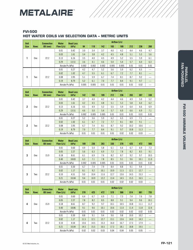
FP–121© 2015 Metal Industries, Inc.
FVI-500 HOT WATER COILS kW SELECTION DATA – METRIC UNITS
Unit Size Rows
Connection OD (mm)
Water Flow (L/s)
Head Loss (kPa)
Airflow (L/s)
94 118 142 165 189 212 236 260
1 One 22.2
0.01 0.42 3.0 3.4 3.7 4.0 4.2 4.4 4.6 4.7
0.03 1.61 3.4 3.8 4.2 4.5 4.8 5.1 5.3 5.6
0.13 6.16 3.5 4.0 4.5 4.9 5.2 5.5 5.9 6.1
0.29 13.51 3.6 4.1 4.6 5.0 5.4 5.7 6.0 6.3
Airside Ps (kPa) 0.002 0.002 0.002 0.005 0.005 0.01 0.01 0.01
1 Two 22.2
0.01 0.27 4.2 4.7 5.2 5.6 5.9 6.2 6.5 —
0.02 1.02 4.7 5.5 6.1 6.7 7.2 7.7 8.1 —
0.08 3.95 5.1 5.9 6.7 7.4 8.1 8.7 9.2 —
0.19 8.79 5.2 6.1 7.0 7.7 8.4 9.1 9.7 —
Airside Ps (kPa) 0.005 0.005 0.01 0.01 0.01 0.01 0.02 —
Unit Size Rows
Connection OD (mm)
Water Flow (L/s)
Head Loss (kPa)
Airflow (L/s)
142 165 189 212 236 283 307 330
2 One 22.2
0.01 0.42 3.7 4.0 4.2 4.4 4.6 4.9 5.0 5.2
0.03 1.61 4.2 4.5 4.8 5.1 5.3 5.8 6.0 6.2
0.13 6.16 4.5 4.9 5.2 5.5 5.9 6.4 6.6 6.9
0.29 13.51 4.6 5.0 5.4 5.7 6.0 6.6 6.9 7.1
Airside Ps (kPa) 0.002 0.005 0.005 0.01 0.01 0.01 0.01 0.01
2 Two 22.2
0.01 0.27 5.2 5.6 5.9 6.2 6.5 6.9 7.1 —
0.02 1.02 6.1 6.7 7.2 7.7 8.1 8.8 9.1 —
0.08 3.95 6.7 7.4 8.1 8.7 9.2 10.2 10.6 —
0.19 8.79 7.0 7.7 8.4 9.1 9.7 10.8 11.3 —
Airside Ps (kPa) 0.01 0.01 0.01 0.01 0.02 0.02 0.03 —
Unit Size Rows
Connection OD (mm)
Water Flow (L/s)
Head Loss (kPa)
Airflow (L/s)
189 236 283 330 378 425 472 566
3 One 15.9
0.01 0.60 4.9 5.4 5.8 6.1 6.4 6.7 6.9 7.3
0.05 2.27 5.6 6.3 6.9 7.3 7.8 8.2 8.5 9.1
0.18 8.61 6.1 6.9 7.6 8.2 8.7 9.2 9.7 10.5
0.40 18.83 6.3 7.1 7.8 8.5 9.1 9.6 10.1 11.0
Airside Ps (kPa) 0.002 0.005 0.005 0.01 0.01 0.01 0.01 0.02
3 Two 22.2
0.01 0.30 6.7 7.4 7.9 8.4 8.8 9.1 9.4 —
0.02 1.17 8.1 9.2 10.1 10.9 11.5 12.1 12.7 —
0.10 4.51 9.0 10.4 11.6 12.7 13.6 14.5 15.3 —
0.21 10.04 9.4 10.9 12.2 13.4 14.5 15.5 16.5 —
Airside Ps (kPa) 0.01 0.01 0.01 0.02 0.02 0.02 0.03 —
Unit Size Rows
Connection OD (mm)
Water Flow (L/s)
Head Loss (kPa)
Airflow (L/s)
378 425 472 519 566 614 661 755
4 One 15.9
0.01 0.60 6.4 6.7 6.9 7.1 7.3 7.4 7.6 7.8
0.05 2.27 7.8 8.2 8.5 8.8 9.1 9.4 9.6 10.1
0.18 8.61 8.7 9.2 9.7 10.1 10.5 10.8 11.1 11.7
0.40 18.86 9.1 9.6 10.1 10.6 11.0 11.4 11.8 12.4
Airside Ps (kPa) 0.01 0.01 0.01 0.02 0.02 0.02 0.02 0.03
4 Two 22.2
0.01 0.30 8.8 9.1 9.4 9.6 9.8 10.0 10.2 —
0.02 1.17 11.5 12.1 12.7 13.1 13.6 14.0 14.3 —
0.10 4.54 13.6 14.5 15.3 16.0 16.7 17.3 17.9 —
0.21 10.04 14.5 15.5 16.5 17.3 18.1 18.8 19.5 —
Airside Ps (kPa) 0.02 0.02 0.03 0.04 0.04 0.05 0.05 —
FVI-5
00
VA
RIA
BLE
VO
LUM
EPA
RA
LLEL FA
N P
OW
ERED
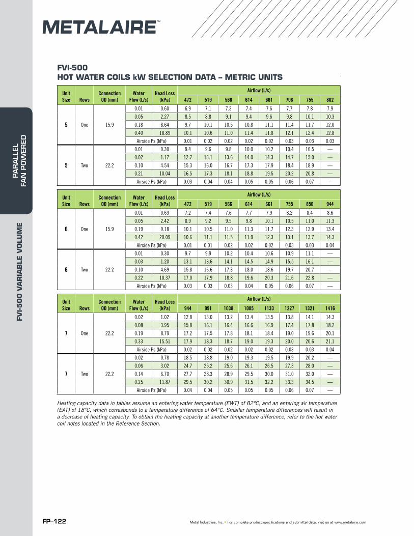
FP–122 Metal Industries, Inc. ■ For complete product specifications and submittal data, visit us at www.metalaire.com
Heating capacity data in tables assume an entering water temperature (EWT) of 82°C, and an entering air temperature (EAT) of 18°C, which corresponds to a temperature difference of 64°C. Smaller temperature differences will result in a decrease of heating capacity. To obtain the heating capacity at another temperature difference, refer to the hot water coil notes located in the Reference Section.
Unit Size Rows
Connection OD (mm)
Water Flow (L/s)
Head Loss (kPa)
Airflow (L/s)
472 519 566 614 661 708 755 802
5 One 15.9
0.01 0.60 6.9 7.1 7.3 7.4 7.6 7.7 7.8 7.9
0.05 2.27 8.5 8.8 9.1 9.4 9.6 9.8 10.1 10.3
0.18 8.64 9.7 10.1 10.5 10.8 11.1 11.4 11.7 12.0
0.40 18.89 10.1 10.6 11.0 11.4 11.8 12.1 12.4 12.8
Airside Ps (kPa) 0.01 0.02 0.02 0.02 0.02 0.03 0.03 0.03
5 Two 22.2
0.01 0.30 9.4 9.6 9.8 10.0 10.2 10.4 10.5 —
0.02 1.17 12.7 13.1 13.6 14.0 14.3 14.7 15.0 —
0.10 4.54 15.3 16.0 16.7 17.3 17.9 18.4 18.9 —
0.21 10.04 16.5 17.3 18.1 18.8 19.5 20.2 20.8 —
Airside Ps (kPa) 0.03 0.04 0.04 0.05 0.05 0.06 0.07 —
Unit Size Rows
Connection OD (mm)
Water Flow (L/s)
Head Loss (kPa)
Airflow (L/s)
472 519 566 614 661 755 850 944
6 One 15.9
0.01 0.63 7.2 7.4 7.6 7.7 7.9 8.2 8.4 8.6
0.05 2.42 8.9 9.2 9.5 9.8 10.1 10.5 11.0 11.3
0.19 9.18 10.1 10.5 11.0 11.3 11.7 12.3 12.9 13.4
0.42 20.09 10.6 11.1 11.5 11.9 12.3 13.1 13.7 14.3
Airside Ps (kPa) 0.01 0.01 0.02 0.02 0.02 0.03 0.03 0.04
6 Two 22.2
0.01 0.30 9.7 9.9 10.2 10.4 10.6 10.9 11.1 —
0.03 1.20 13.1 13.6 14.1 14.5 14.9 15.5 16.1 —
0.10 4.69 15.8 16.6 17.3 18.0 18.6 19.7 20.7 —
0.22 10.37 17.0 17.9 18.8 19.6 20.3 21.6 22.8 —
Airside Ps (kPa) 0.03 0.03 0.03 0.04 0.05 0.06 0.07 —
Unit Size Rows
Connection OD (mm)
Water Flow (L/s)
Head Loss (kPa)
Airflow (L/s)
944 991 1038 1085 1133 1227 1321 1416
7 One 22.2
0.02 1.02 12.8 13.0 13.2 13.4 13.5 13.8 14.1 14.3
0.08 3.95 15.8 16.1 16.4 16.6 16.9 17.4 17.8 18.2
0.19 8.79 17.2 17.5 17.8 18.1 18.4 19.0 19.6 20.1
0.33 15.51 17.9 18.3 18.7 19.0 19.3 20.0 20.6 21.1
Airside Ps (kPa) 0.02 0.02 0.02 0.02 0.02 0.03 0.03 0.04
7 Two 22.2
0.02 0.78 18.5 18.8 19.0 19.3 19.5 19.9 20.2 —
0.06 3.02 24.7 25.2 25.6 26.1 26.5 27.3 28.0 —
0.14 6.70 27.7 28.3 28.9 29.5 30.0 31.0 32.0 —
0.25 11.87 29.5 30.2 30.9 31.5 32.2 33.3 34.5 —
Airside Ps (kPa) 0.04 0.04 0.05 0.05 0.05 0.06 0.07 —
FVI-500 HOT WATER COILS kW SELECTION DATA – METRIC UNITS
FVI-5
00
VA
RIA
BLE
VO
LUM
EPA
RA
LLEL
FA
N P
OW
ERED
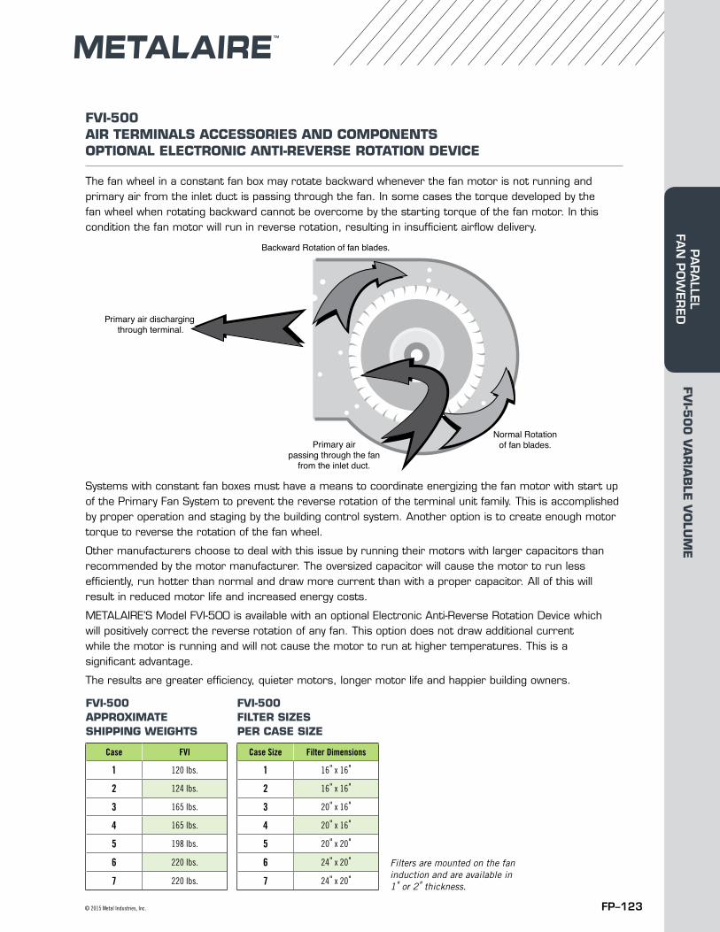
FP–123© 2015 Metal Industries, Inc.
FVI-500 AIR TERMINALS ACCESSORIES AND COMPONENTS OPTIONAL ELECTRONIC ANTI-REVERSE ROTATION DEVICE
The fan wheel in a constant fan box may rotate backward whenever the fan motor is not running and primary air from the inlet duct is passing through the fan. In some cases the torque developed by the fan wheel when rotating backward cannot be overcome by the starting torque of the fan motor. In this condition the fan motor will run in reverse rotation, resulting in insufficient airflow delivery.
Systems with constant fan boxes must have a means to coordinate energizing the fan motor with start up of the Primary Fan System to prevent the reverse rotation of the terminal unit family. This is accomplished by proper operation and staging by the building control system. Another option is to create enough motor torque to reverse the rotation of the fan wheel.
Other manufacturers choose to deal with this issue by running their motors with larger capacitors than recommended by the motor manufacturer. The oversized capacitor will cause the motor to run less efficiently, run hotter than normal and draw more current than with a proper capacitor. All of this will result in reduced motor life and increased energy costs.
METALAIRE’S Model FVI-500 is available with an optional Electronic Anti-Reverse Rotation Device which will positively correct the reverse rotation of any fan. This option does not draw additional current while the motor is running and will not cause the motor to run at higher temperatures. This is a significant advantage.
The results are greater efficiency, quieter motors, longer motor life and happier building owners.
FVI-500 APPROXIMATE SHIPPING WEIGHTS
FVI-500 FILTER SIZES PER CASE SIZE
Case FVI
1 120 lbs.
2 124 lbs.
3 165 lbs.
4 165 lbs.
5 198 lbs.
6 220 lbs.
7 220 lbs.
Case Size Filter Dimensions
1 16" x 16"
2 16" x 16"
3 20" x 16"
4 20" x 16"
5 20" x 20"
6 24" x 20"
7 24" x 20"
Primary airpassing through the fan
from the inlet duct.
Primary air dischargingthrough terminal.
Normal Rotationof fan blades.
Backward Rotation of fan blades.
Filters are mounted on the fan induction and are available in 1" or 2" thickness.
FVI-5
00
VA
RIA
BLE
VO
LUM
EPA
RA
LLEL FA
N P
OW
ERED
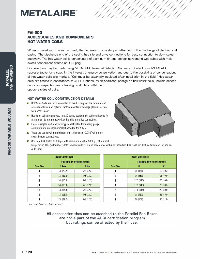
FP–124 Metal Industries, Inc. ■ For complete product specifications and submittal data, visit us at www.metalaire.com
FVI-500 ACCESSORIES AND COMPONENTSHOT WATER COILS
When ordered with the air terminal, the hot water coil is shipped attached to the discharge of the terminal casing. The discharge end of the casing has slip and drive connections for easy connection to downstream ductwork. The hot water coil is constructed of aluminum fin and copper serpentine-type tubes with male sweat connections tested at 300 psig.
Coil selection may be made using METALAIRE Terminal Selection Software. Contact your METALAIRE representative for a copy. In the interest of energy conservation and due to the possibility of condensation, all hot water coils are marked, “Coil must be externally insulated after installation in the field.” Hot water coils are tested in accordance to AHRI. Options, at an additional charge on hot water coils, include access doors for inspection and cleaning, and inlet/outlet on opposite sides of coils.
HOT WATER COIL CONSTRUCTION DETAILS■ Hot Water Coils are factory mounted to the discharge of the terminal and
are available with an optional factory mounted discharge plenum section with access door.
■ Hot water coils are enclosed in a 20 gauge coated steel casing allowing for attachment to metal ductwork with a slip and drive connection.
■ Fins are rippled and sine wave type constructed from heavy gauge aluminum and are mechanically bonded to the tubes.
■ Tubes are copper with a minimum wall thickness of 0.016" with male sweat header connections.
■ Coils are leak tested to 300 psi with minimum burst of 2000 psi at ambient temperature. Coil performance data is based on tests run in accordance with AHRI standard 410. Coils are AHRI certified and include an AHRI label.
Tubing Connections
Case Size
Standard HW Coil Inches (mm)
1 Row 2 Row
1 7/8 (22.2) 7/8 (22.2)
2 7/8 (22.2) 7/8 (22.2)
3 5/8 (15.8) 7/8 (22.2)
4 5/8 (15.8) 7/8 (22.2)
5 7/8 (15.8) 7/8 (22.2)
6 7/8 (15.8) 7/8 (22.2)
7 7/8 (22.2) 7/8 (22.2)
All coils have 10 fins per inch
Outlet Dimensions
Case Size
Standard HW Coil Inches (mm)
H W
1 15 (381) 16 (406)
2 15 (381) 16 (406)
3 17.5 (445) 20 (508)
4 17.5 (445) 20 (508)
5 17.5 (445) 20 (508)
6 18 (457) 22 (559)
7 20 (508) 30 (718)
All accessories that can be attached to the Parallel Fan Boxes are not a part of the AHRI certification program
but ratings can be affected by their use.
FVI-5
00
VA
RIA
BLE
VO
LUM
EPA
RA
LLEL
FA
N P
OW
ERED
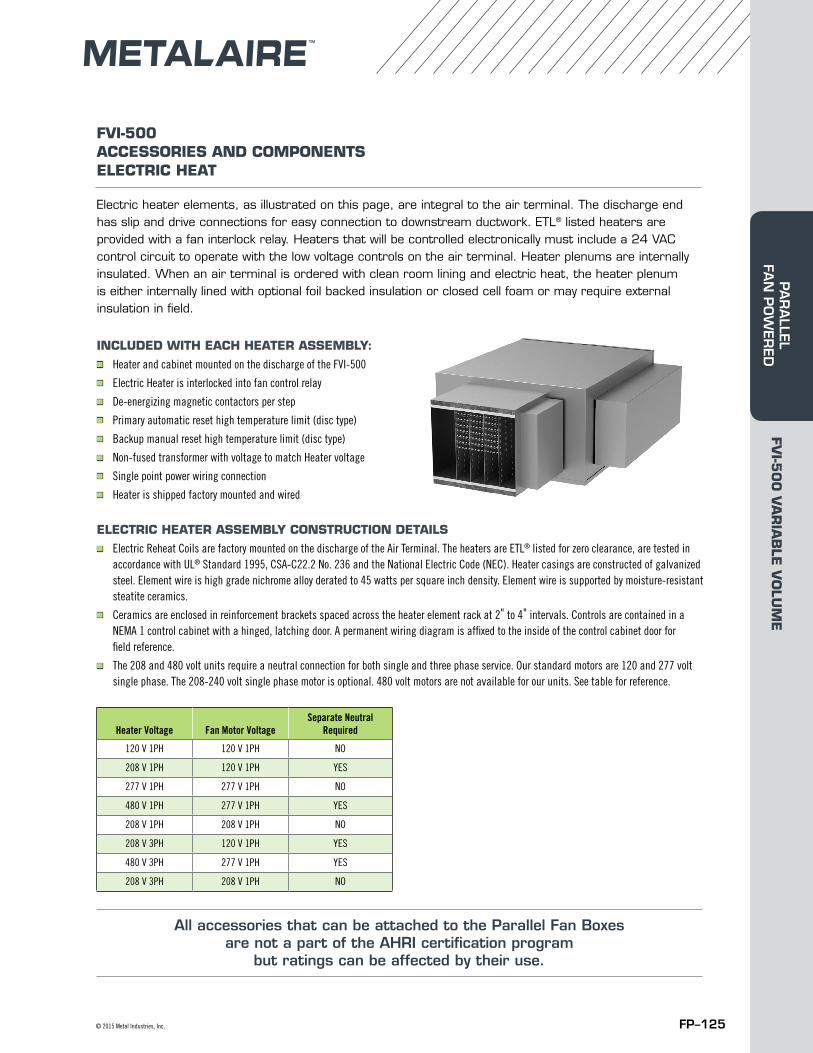
FP–125© 2015 Metal Industries, Inc.
FVI-500 ACCESSORIES AND COMPONENTSELECTRIC HEAT
Electric heater elements, as illustrated on this page, are integral to the air terminal. The discharge end has slip and drive connections for easy connection to downstream ductwork. ETL® listed heaters are provided with a fan interlock relay. Heaters that will be controlled electronically must include a 24 VAC control circuit to operate with the low voltage controls on the air terminal. Heater plenums are internally insulated. When an air terminal is ordered with clean room lining and electric heat, the heater plenum is either internally lined with optional foil backed insulation or closed cell foam or may require external insulation in field.
INCLUDED WITH EACH HEATER ASSEMBLY:■ Heater and cabinet mounted on the discharge of the FVI-500■ Electric Heater is interlocked into fan control relay■ De-energizing magnetic contactors per step■ Primary automatic reset high temperature limit (disc type)■ Backup manual reset high temperature limit (disc type)■ Non-fused transformer with voltage to match Heater voltage■ Single point power wiring connection■ Heater is shipped factory mounted and wired
ELECTRIC HEATER ASSEMBLY CONSTRUCTION DETAILS■ Electric Reheat Coils are factory mounted on the discharge of the Air Terminal. The heaters are ETL® listed for zero clearance, are tested in
accordance with UL® Standard 1995, CSA-C22.2 No. 236 and the National Electric Code (NEC). Heater casings are constructed of galvanized steel. Element wire is high grade nichrome alloy derated to 45 watts per square inch density. Element wire is supported by moisture-resistant steatite ceramics.
■ Ceramics are enclosed in reinforcement brackets spaced across the heater element rack at 2" to 4" intervals. Controls are contained in a NEMA 1 control cabinet with a hinged, latching door. A permanent wiring diagram is affixed to the inside of the control cabinet door for field reference.
■ The 208 and 480 volt units require a neutral connection for both single and three phase service. Our standard motors are 120 and 277 volt single phase. The 208-240 volt single phase motor is optional. 480 volt motors are not available for our units. See table for reference.
Heater Voltage Fan Motor VoltageSeparate Neutral
Required
120 V 1PH 120 V 1PH NO
208 V 1PH 120 V 1PH YES
277 V 1PH 277 V 1PH NO
480 V 1PH 277 V 1PH YES
208 V 1PH 208 V 1PH NO
208 V 3PH 120 V 1PH YES
480 V 3PH 277 V 1PH YES
208 V 3PH 208 V 1PH NO
All accessories that can be attached to the Parallel Fan Boxes are not a part of the AHRI certification program
but ratings can be affected by their use.
FVI-5
00
VA
RIA
BLE
VO
LUM
EPA
RA
LLEL FA
N P
OW
ERED
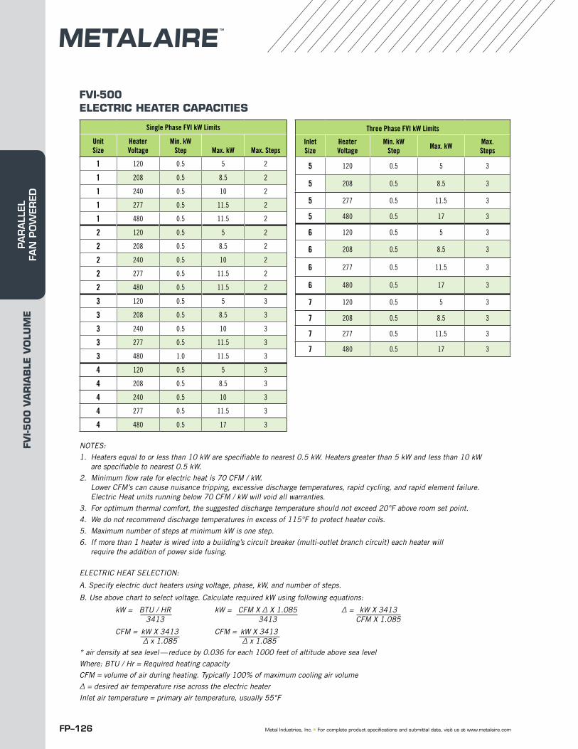
FP–126 Metal Industries, Inc. ■ For complete product specifications and submittal data, visit us at www.metalaire.com
FVI-500 ELECTRIC HEATER CAPACITIES
NOTES:1. Heaters equal to or less than 10 kW are specifiable to nearest 0.5 kW. Heaters greater than 5 kW and less than 10 kW
are specifiable to nearest 0.5 kW.2. Minimum flow rate for electric heat is 70 CFM / kW.
Lower CFM’s can cause nuisance tripping, excessive discharge temperatures, rapid cycling, and rapid element failure. Electric Heat units running below 70 CFM / kW will void all warranties.
3. For optimum thermal comfort, the suggested discharge temperature should not exceed 20°F above room set point.4. We do not recommend discharge temperatures in excess of 115°F to protect heater coils.5. Maximum number of steps at minimum kW is one step.6. If more than 1 heater is wired into a building’s circuit breaker (multi-outlet branch circuit) each heater will
require the addition of power side fusing.
ELECTRIC HEAT SELECTION:
A. Specify electric duct heaters using voltage, phase, kW, and number of steps.
B. Use above chart to select voltage. Calculate required kW using following equations:
kW = BTU / HR kW = CFM X ∆ X 1.085 ∆ = kW X 3413 3413 3413 CFM X 1.085
CFM = kW X 3413 CFM = kW X 3413 ∆ x 1.085 ∆ x 1.085* air density at sea level — reduce by 0.036 for each 1000 feet of altitude above sea levelWhere: BTU / Hr = Required heating capacityCFM = volume of air during heating. Typically 100% of maximum cooling air volume∆ = desired air temperature rise across the electric heaterInlet air temperature = primary air temperature, usually 55°F
Single Phase FVI kW Limits
Unit Size
Heater Voltage
Min. kW Step Max. kW Max. Steps
1 120 0.5 5 2
1 208 0.5 8.5 2
1 240 0.5 10 2
1 277 0.5 11.5 2
1 480 0.5 11.5 2
2 120 0.5 5 2
2 208 0.5 8.5 2
2 240 0.5 10 2
2 277 0.5 11.5 2
2 480 0.5 11.5 2
3 120 0.5 5 3
3 208 0.5 8.5 3
3 240 0.5 10 3
3 277 0.5 11.5 3
3 480 1.0 11.5 3
4 120 0.5 5 3
4 208 0.5 8.5 3
4 240 0.5 10 3
4 277 0.5 11.5 3
4 480 0.5 17 3
Three Phase FVI kW Limits
Inlet Size
Heater Voltage
Min. kW Step Max. kW Max.
Steps
5 120 0.5 5 3
5 208 0.5 8.5 3
5 277 0.5 11.5 3
5 480 0.5 17 3
6 120 0.5 5 3
6 208 0.5 8.5 3
6 277 0.5 11.5 3
6 480 0.5 17 3
7 120 0.5 5 3
7 208 0.5 8.5 3
7 277 0.5 11.5 3
7 480 0.5 17 3
FVI-5
00
VA
RIA
BLE
VO
LUM
EPA
RA
LLEL
FA
N P
OW
ERED
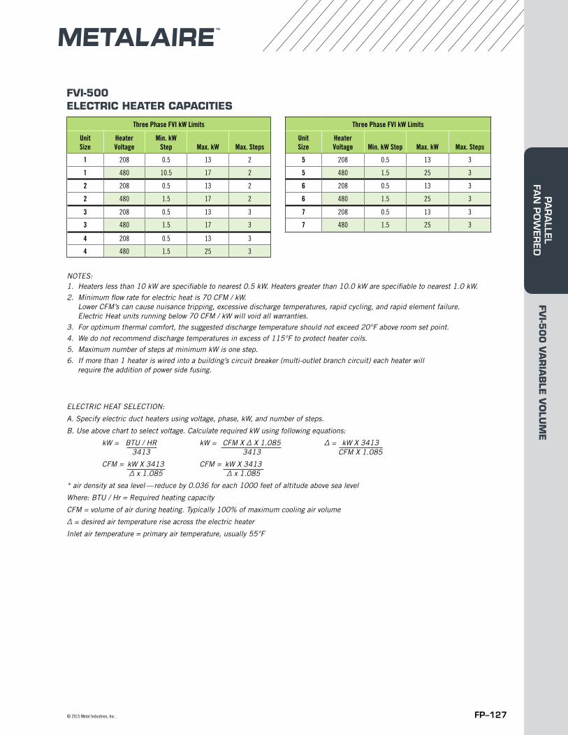
FP–127© 2015 Metal Industries, Inc.
FVI-500 ELECTRIC HEATER CAPACITIES
Three Phase FVI kW Limits Three Phase FVI kW Limits
Unit Size
Heater Voltage
Min. kW Step Max. kW Max. Steps
Unit Size
Heater Voltage Min. kW Step Max. kW Max. Steps
1 208 0.5 13 2 5 208 0.5 13 3
1 480 10.5 17 2 5 480 1.5 25 3
2 208 0.5 13 2 6 208 0.5 13 3
2 480 1.5 17 2 6 480 1.5 25 3
3 208 0.5 13 3 7 208 0.5 13 3
3 480 1.5 17 3 7 480 1.5 25 3
4 208 0.5 13 3
4 480 1.5 25 3
NOTES:1. Heaters less than 10 kW are specifiable to nearest 0.5 kW. Heaters greater than 10.0 kW are specifiable to nearest 1.0 kW.2. Minimum flow rate for electric heat is 70 CFM / kW.
Lower CFM’s can cause nuisance tripping, excessive discharge temperatures, rapid cycling, and rapid element failure. Electric Heat units running below 70 CFM / kW will void all warranties.
3. For optimum thermal comfort, the suggested discharge temperature should not exceed 20°F above room set point.4. We do not recommend discharge temperatures in excess of 115°F to protect heater coils.5. Maximum number of steps at minimum kW is one step.6. If more than 1 heater is wired into a building’s circuit breaker (multi-outlet branch circuit) each heater will
require the addition of power side fusing.
ELECTRIC HEAT SELECTION:
A. Specify electric duct heaters using voltage, phase, kW, and number of steps.
B. Use above chart to select voltage. Calculate required kW using following equations:
kW = BTU / HR kW = CFM X ∆ X 1.085 ∆ = kW X 3413 3413 3413 CFM X 1.085
CFM = kW X 3413 CFM = kW X 3413 ∆ x 1.085 ∆ x 1.085
* air density at sea level — reduce by 0.036 for each 1000 feet of altitude above sea level
Where: BTU / Hr = Required heating capacity
CFM = volume of air during heating. Typically 100% of maximum cooling air volume
∆ = desired air temperature rise across the electric heater
Inlet air temperature = primary air temperature, usually 55°F
FVI-5
00
VA
RIA
BLE
VO
LUM
EPA
RA
LLEL FA
N P
OW
ERED
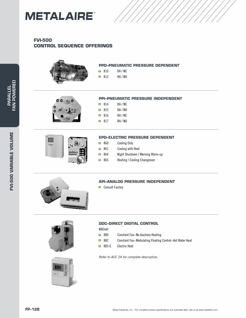
FP–128 Metal Industries, Inc. ■ For complete product specifications and submittal data, visit us at www.metalaire.com
PPD–PNEUMATIC PRESSURE DEPENDENT■ 810 DA / NC■ 812 RA / NO
PPI–PNEUMATIC PRESSURE INDEPENDENT■ 814 DA / NC■ 815 DA / NO■ 816 RA / NC■ 817 RA / NO
EPD–ELECTRIC PRESSURE DEPENDENT■ 860 Cooling Only■ 861 Cooling with Heat■ 864 Night Shutdown / Morning Warm-up■ 865 Heating / Cooling Changeover
API–ANALOG PRESSURE INDEPENDENT ■ Consult Factory
DDC–DIRECT DIGITAL CONTROL
BACnet■ 880 Constant Fan–No Auxiliary Heating■ 882 Constant Fan–Modulating Floating Control–Hot Water Heat■ 883-E Electric Heat
Refer to ACC 24 for complete description.
FVI-500CONTROL SEQUENCE OFFERINGS
FVI-5
00
VA
RIA
BLE
VO
LUM
EPA
RA
LLEL
FA
N P
OW
ERED
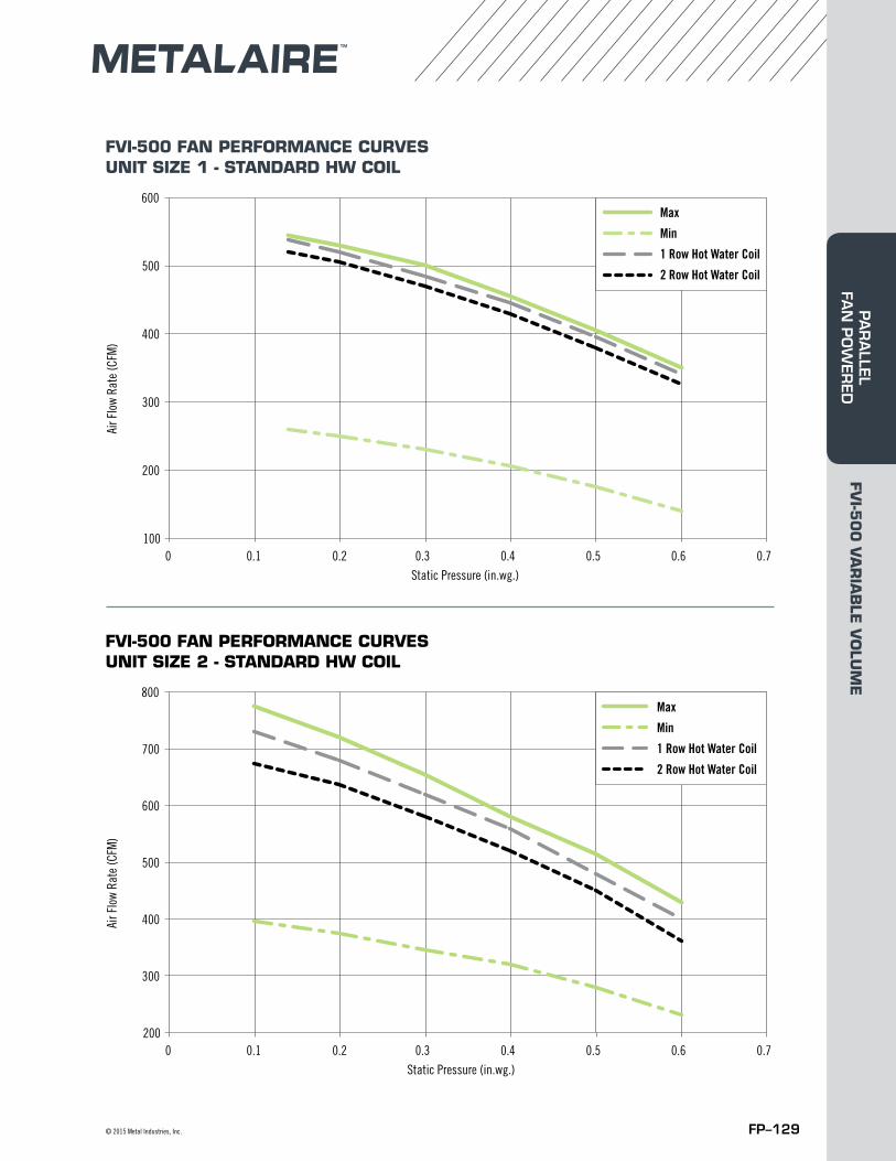
FP–129© 2015 Metal Industries, Inc.
FVI-500 FAN PERFORMANCE CURVESUNIT SIZE 1 - STANDARD HW COIL
FVI-500 FAN PERFORMANCE CURVESUNIT SIZE 2 - STANDARD HW COIL
100
200
300
400
500
600
0 0.1 0.2 0.3 0.4 0.5 0.6 0.7
Air F
low
Rate
(CFM
)
Static Pressure (in.wg.)
FVI Unit Size 1Standard HW Coil
Max
Min
1 Row Hot Water Coil
2 Row Hot Water Coil
200
300
400
500
700
600
800
0 0.1 0.2 0.3 0.4 0.5 0.6 0.7
Air F
low
Rate
(CFM
)
Static Pressure (in.wg.)
FVI Unit Size 2Standard HW Coil
Max
Min
1 Row Hot Water Coil
2 Row Hot Water Coil
FVI-5
00
VA
RIA
BLE
VO
LUM
EPA
RA
LLEL FA
N P
OW
ERED
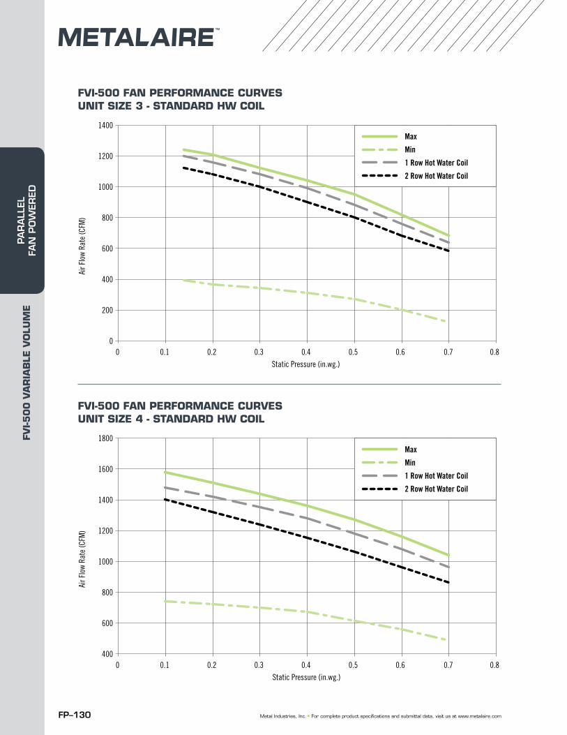
FP–130 Metal Industries, Inc. ■ For complete product specifications and submittal data, visit us at www.metalaire.com
FVI-500 FAN PERFORMANCE CURVESUNIT SIZE 3 - STANDARD HW COIL
FVI-500 FAN PERFORMANCE CURVESUNIT SIZE 4 - STANDARD HW COIL
0
200
400
600
1200
1000
800
1400
0 0.1 0.2 0.3 0.4 0.5 0.6 0.7 0.8
Air F
low
Rate
(CFM
)
Static Pressure (in.wg.)
FVI Unit Size 3Standard HW Coil
Max
Min
1 Row Hot Water Coil
2 Row Hot Water Coil
400
600
800
1000
1600
1400
1200
1800
0 0.1 0.2 0.3 0.4 0.5 0.6 0.7 0.8
Air F
low
Rate
(CFM
)
Static Pressure (in.wg.)
FVI Unit Size 4Standard HW Coil
Max
Min
1 Row Hot Water Coil
2 Row Hot Water Coil
FVI-5
00
VA
RIA
BLE
VO
LUM
EPA
RA
LLEL
FA
N P
OW
ERED
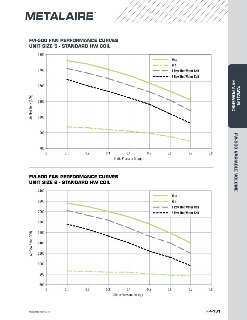
FP–131© 2015 Metal Industries, Inc.
FVI-500 FAN PERFORMANCE CURVESUNIT SIZE 5 - STANDARD HW COIL
FVI-500 FAN PERFORMANCE CURVESUNIT SIZE 6 - STANDARD HW COIL
700
900
1100
1300
1700
1500
1900
0 0.1 0.2 0.3 0.4 0.5 0.6 0.7 0.8
Air F
low
Rate
(CFM
)
Static Pressure (in.wg.)
FVI Unit Size 5Standard HW Coil
Max
Min
1 Row Hot Water Coil
2 Row Hot Water Coil
600
800
1000
1400
2000
1200
2200
1600
1800
2400
0 0.1 0.2 0.3 0.4 0.5 0.6 0.7 0.8
Air F
low
Rate
(CFM
)
Static Pressure (in.wg.)
FVI Unit Size 6Standard HW Coil
Max
Min
1 Row Hot Water Coil
2 Row Hot Water Coil
FVI-5
00
VA
RIA
BLE
VO
LUM
EPA
RA
LLEL FA
N P
OW
ERED
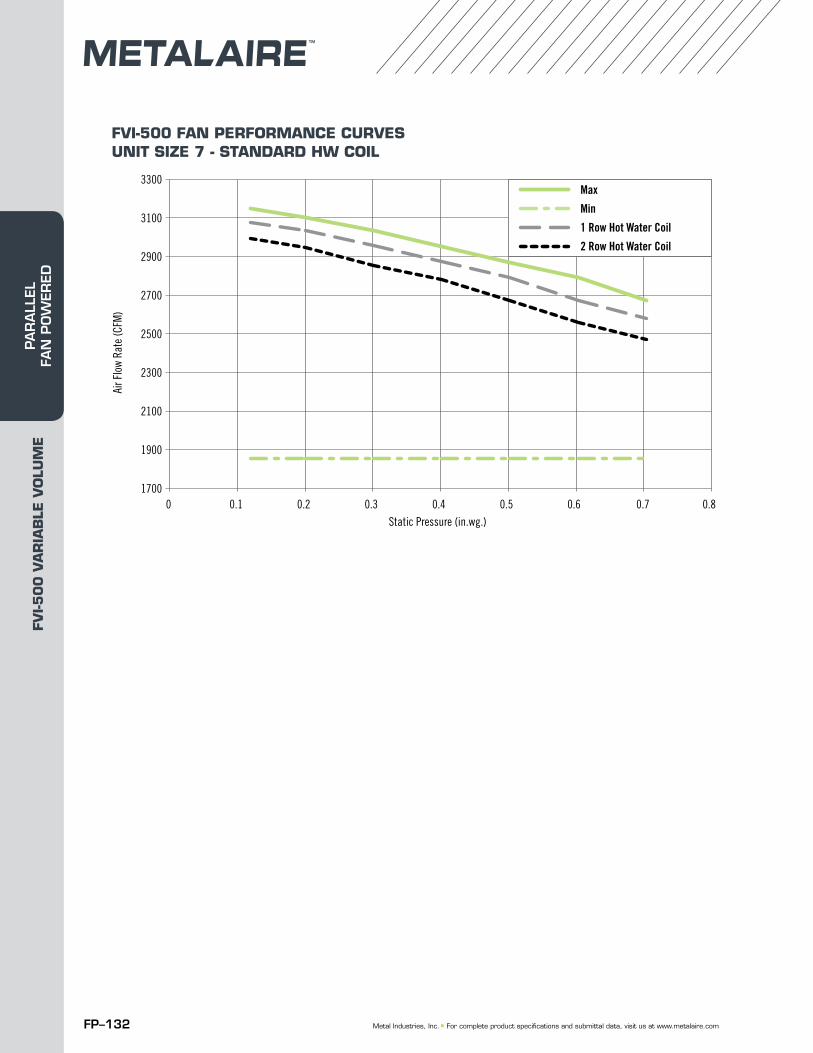
FP–132 Metal Industries, Inc. ■ For complete product specifications and submittal data, visit us at www.metalaire.com
FVI-500 FAN PERFORMANCE CURVESUNIT SIZE 7 - STANDARD HW COIL
1700
1900
2100
2300
2900
2700
2500
3300
3100
0 0.1 0.2 0.3 0.4 0.5 0.6 0.7 0.8
Air F
low
Rate
(CFM
)
Static Pressure (in.wg.)
FVI Unit Size 7Standard HW Coil
Max
Min
1 Row Hot Water Coil
2 Row Hot Water Coil
FVI-5
00
VA
RIA
BLE
VO
LUM
EPA
RA
LLEL
FA
N P
OW
ERED
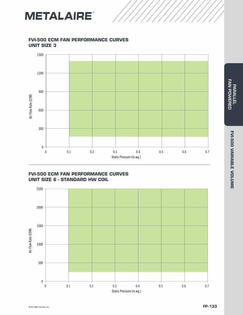
FP–133© 2015 Metal Industries, Inc.
FVI-500 ECM FAN PERFORMANCE CURVESUNIT SIZE 3
FVI-500 ECM FAN PERFORMANCE CURVESUNIT SIZE 6 - STANDARD HW COIL
0
900
600
300
1200
1500
0 0.2 0.3 0.4 0.5 0.7 0.1 0.6
Air F
low
Rate
(CFM
)
FVI ECM Case 3Standard HW Coil
Static Pressure (in.wg.)
0
1500
1000
500
2000
2500
0 0.2 0.3 0.4 0.5 0.7 0.1 0.6
Air F
low
Rate
(CFM
)
FVI ECM Case 6Standard HW Coil
Static Pressure (in.wg.)
FVI-5
00
VA
RIA
BLE
VO
LUM
EPA
RA
LLEL FA
N P
OW
ERED
FP–134 Metal Industries, Inc. ■ For complete product specifications and submittal data, visit us at www.metalaire.com
FVI-5
00
VA
RIA
BLE
VO
LUM
EPA
RA
LLEL
FA
N P
OW
ERED