Embed Size (px)
Citation preview
as amended September 26, 1989
CHESTNUT HILLRESERVOIR
ANDPUMP STATIONS
Boston Landmarks CommissionEnvironment DepartmentCity of Boston

as amended September 26, 1989
Report of the Boston Landmark Commissionon the Potential Designation of
THE CHESTNUT HILL RESERVOIR AND PUMPING STATIONSas a
LANDMARK
under Chapter 772 of the Acts of 1975, as amended

Gratitude is expressed to Ellen J. LipseyFor her research and contributions to this study report.
CONTENTS
1.0 Location of the Property under Consideration 1
2.0 Description of the Property 3
3.0 Significance of the Property 33
4.0 Economic Status 47
5.0 Planning Context 49
6.0 Alternate Approaches 53
7.0 Recommendations 55
8.0 General Standards and Criteria 57
9.0 Specific Standards and Criteria 65
10.0 Bibliography and Notes 69

1.0 LOCATION OF THE PROPERTY
1.1 The address for the Low Service2400 Beacon Street; the addressstation is 2450 Beacon Street.are 2439, 2472, most of 2442-5.
reservoir pumping station isfor the High Service pumpingThe assessor's parcel numbers
The complex is in ward 21.
Boundary: - The area petitioned for Landmarks designation iscomprised of: parcel 2439 which includes the high and lowservice pump stations, ancillary buildings and surroundingproperty; parcel 2472, which includes the reservoir, gatehouses and surrounding greenbelt; and, parcel 2442-5 whichincludes the Chestnut Hill Driveway, St. Thomas More Road andsurrounding greenbelt.
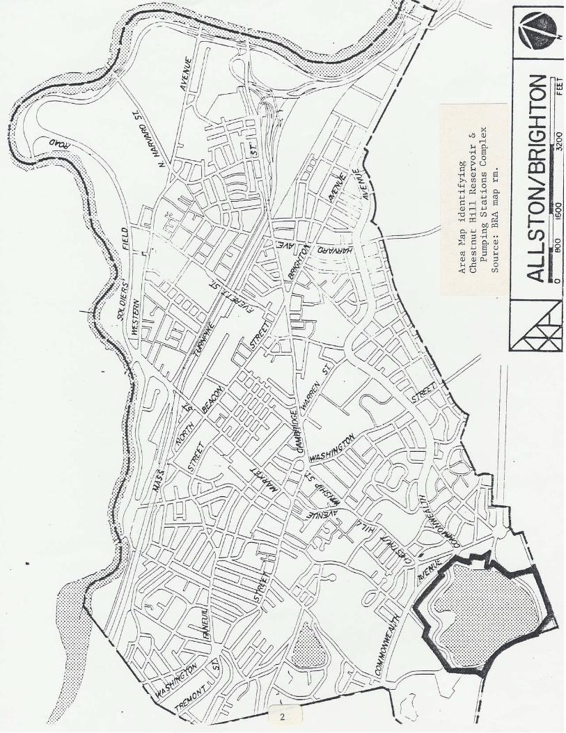
1.2 Area in which the property is located: Chestnut HillReservoir is located in Brighton, approximately 5 milessouthwest of downtown Boston via Beacon Street, and about 11/2 mile south of the Charles River and the MassachusettsTurnpike extension (1-90). The reservoir and its facilitiesare named for Chestnut Hill, the area where Brookline,Newton, and Brighton converge. Major roads nearby areCommonwealth Avenue, Chestnut Hill Avenue, and Beacon Streetwhich crosses the property. The property shares borders withthe MBTA Riverside line, Brookline, Newton, Boston College,Evergreen Cemetery, Cassidy Playground, and the MDCpool/Reilly Ice Rink park area.
The Allston-Brighton district is predominantly residential,with three major commercial areas and some industrial land.The petitioned property is adjacent to Boston College; thereis a large student population in the immediate area. Thecity ranks Allston-Brighton in the middle of Boston's 19districts with respect to population density and open spaceacreage.
1.3 Maps showing location: following.
1


2.0 DESCRIPTION OF THE PROPERTY
2.1 Type and use: The Chestnut Hill Reservoir complex iscomprised of the Bradlee Basin, two gatehouses on itsembankment, the Chestnut Hill Driveway and greenbelt, twopumping stations, several ancillary service structures, andtwo structures in Newton which are outside the purview of theBoston Landmarks Commission. The combined land area isapproximately 135 acres. The reservoir, two gate houses (onein Newton), both pumping stations and service buildings areused by the Massachusetts Resource Authority (MWRA) on astand-by basis to maintain adequate pressure in the system.Water service can be activated if it is needed, and thefacilities are staffed year-round.
Joggers and walkers use the path around the basin; the outerpath is open to the public, the inner one has been sealed offbehind an iron fence for reasons of health and safety. TheChestnut Hill Driveway is posted "For Pleasure VehiclesOnly", it includes parking and is framed by a woodedgreenbelt area along the north border of the parkway.Through-traffic on Beacon Street separates the basin from thepumping station area; the western end of the Chestnut HillDriveway serves traffic at the eastern end of the BostonCollege campus.
2.2 Physical description: The site was originally a naturalbasin with marsh and meadow lands. Above the shore, betweenBeacon Street and Commonwealth Avenue is a hilly area withrocky outcroppings and mature trees, including oaks andevergreens. Adjacent to the reservoir fence, on thenortheast side, is a par (exercise) course and foot paths.Between the fence and the water's edge are field grass,mature trees, rock outcroppings and the original inner path.The Driveway and parkway area are on a relatively flat gradewith well-maintained landscape including mature trees, grass,and rock outcroppings. Many of the trees on the propertyappear to date from at least the original development of thereservoir in 1866-70, and from the building of the pumpingstations in the 1880s and 1890s.
The following components make up the Chestnut Hill Reservoircomplex. They are described in chronological order bycompletion date.
Bradlee Basin - The parcel containing the basin isapproximately 110 acres. According to figures at the time ofconstruction, the water covers 87 1/2 acres. The averagedepth is 20 feet and there is a capacity of about 550,600,000gallons. The elevation of the reservoir is 125 feet. Theembankment is built up in places to a maximum height of 35feet. It is sodded, and in places is topped by the originalgravel footpath, which is 8 feet wide, 1.57 miles long andcircles the basin.
5

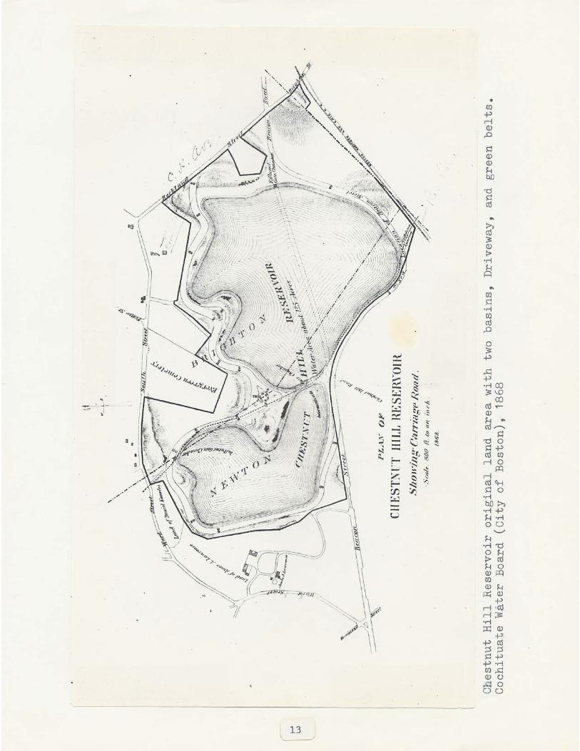
The inner slope of the basin is lined with dry laid rubblestone 2 1/2 feet thick which extends down 19 1/2 feet on theslope to a berm and riprap reinforcement at the foot. Theslope lining is capped with granite blocks about 3 feet belowthe top of the embankment. Bradlee Basin was originallypaired with an upper (higher) basin, the Lawrence Meadow,which was constructed at the same time and had less than halfthe capacity of Bradlee. The upper basin was sold to BostonCollege in 1949, and filled for a playing field and otherfacilities in 1950. The dam which separated the two basinsserves as part of the Bradlee embankment and the road bed forpart of the Driveway. The fence, with pineapple shapedfinials, is extant in many places. Additional new fence wasrequired when the boundary of the Reservoir was moved fromthe shoreline to the shoulder of the slope to help preventdebris from collecting and entering the water. At the sametime the inner path was sealed off and the outer path wasdeveloped so that the reservoir would continue to serve therecreational needs of the community. The work was done forthe MDC by Coughlan Construction Co, Inc. with landscapeplans provided by Storch Associates.
Chestnut Hill Driveway and Landscaping - Part of theoriginal Driveway, constructed around both basins in 1866-70,is extant at the north and western shoreline of BradleeBasin, running from Commonwealth Avenue to Beacon Street.Including the parkway greenbelt it comprises about 16 acres.The northern portion is serpentine in plan. The 1977blacktop surfacing is cut away at intervals, exposing theoriginal granite paving blocks which act a's speed bumps.Angle parking is provided in the margins within the original80-foot width of the driveway. There is an overlook areanear the Commonwealth Avenue end built in 1977 with a granitebench, pavers, and a stone plaque which shows the distancefrom Bradlee Basin to other MDC water supplies. Other 1977additions to the landscape include stone walls at eachentrance of the drive, with plaques reading "Chestnut HillReservoir, Metropolitan District Commission, Commonwealth ofMassachusetts" and pedestrian crossings laid with new granitepavers. The granite curbing along the drive also appears tohave been done in 1977.
The wooded greenbelt area provides a buffer between theDriveway and housing north of the reservoir; it abutsEvergreen Cemetery at the northwest bend of the drive. Allof the landscape additions done in 1977 are compatible indesign, scale and materials, with the existing landscape.
G

Originally, a large pastoral park was laid out at the easternedge of the Reservoir at the current site of the Cassidyplayground (owned by the City of Boston) and Reilly MemorialIce Skating Rink (owned by the MDC). Remnants of theoriginal landscaping exist along the northeast edge of parcel2473 and on either side of the Chestnut Hill Driveway alongthe northern edge of the Reservoir. This landscape ischaracterized by groves of trees, rocky outcroppings andother informal, naturalistic features.
Original Effluent Gate House - Constructed c. 1869, thisgate house is located on the edge of the basin near ClevelandCircle. It is a two level square structure with a hip roofand a central ventilator at the roof apex (the ventilator haslost its original cap). The walls are dressed granite ashlarin random rangework with darker rock-faced quoins and windowsurrounds. The structure is three bays across; theround-headed windows have been bricked in. The building wasconstructed on quick sand with rubble piers and brick archesresting on bedrock. In addition, granite sidewalls, anearthen bulkhead and brick groined arches are required. Thegranite foundation above the water line and the monumentalgranite double stairway facing Cleveland Circle relate to thebasement structure of aqueduct and main connections.
Intermediate Gate House (not within study area) - Built onthe dam between the basins this building belongs to BostonCollege and is now located at the edge of their playingfield. It is no longer operated by MDC or"MWRA. This simplelooking granite block regulated the water between the basins;it dates from 1866-70. Boston College demolished theoriginal Influent Gate House in 1950 which was located on thenorthwest shore of Lawr~nce Basin and which let water intothe reservoir from the Cochituate aqueduct.
Sudbury Terminal Chamber (not within study area) Originally built for the city of Boston, this building islocated in Newton on Beacon Street opposite the Drivewayentrance. It is the terminus of the Sudbury aqueduct systemwhich was completed in 1878, and houses five aqueduct gates.The walls consist of smooth and rock faced granite ashlar. Arow of five arched windows, mirrored below by five stonedisks, symbolize the five pipe connections. The strikingbuilding appears to have been influenced by the designs ofPhiladelphia architect, Frank Furness.
High Service Pumping Station - This is the first pumpingstation at Chestnut Hill, built 1887-88 to supply highpressure water service for distribution to the higherelevations of newly annexed areas of Boston. It is locatedon the south side of Beacon Street opposite the reservoirbetween Cleveland Circle and the Newton city line. The HighService station is an asymmetrical picturesque composition inthe Richardsonian Romanesque style.
7

The massing is horizontal. Three main gable roofs rise instages from east to west, punctuated east of center with a150-foot rear smokestack and in front by a 112-foot, hippedroof tower with an open observatory at the top. The originalstructure is comprised of a 84' 10" x 64' 8" engine room; a79' 10" x 56' 2" boiler room; a 62' x 65' 4" coal pocket;and, a 43' 8" x 19' 10" addition. The 2 1/2 story buildingfeatures assymetrical fenestration, with rectangular andarched windows in groups of two and three.
The main Syrian entrance arch balances the left-hand towersomewhat as it is offset to the right of the central gabledentrance pavilion. The doorway leads directly into theoriginal engine room. To the extreme left, at thestructure's lowest point is ~he coal storage area. The rightgabled wing is an addition which was added in 1897-99 tohouse another engine. The date 1897 appears on thecrossgable end which forms the west elevation of thestation. The original plans allowed for this expansion. Thepavilions forming the separate rooms articulate functions andare impressive in terms of scale and detail.
Characteristic of the Richardsonian style, the high servicebuilding displays a variety of textures and colors. Thefront and side elevations of the station are rockfacedMilford granite ashlar laid in random rangework. The boldreddish brown trim is Longmeadow freestone, used chiefly forhorizontal banding and window and door surrounds. Theexterior elevations are primarily pink andbrowl1 in color.The roof is blue-grey slate with oxidized copper flashing andcornices. A bronze sign over the doorway reads "MetropolitanWater Works", replacing an earlier "Boston Water Works" nameplate.
The tall smokestack and the rear elevation are red brick.There are railroad tracks behind the building where theBoston & Albany Railroad unloaded coal to power the boilersfor steam-driven pumps. The tracks now serve the MBTARiverside line and the rear elevation of the station showsmany additions and alterations.
The building has masonry walls with iron roof trusses in theoriginal engine room. For the 1897-99 addition steel wasused for the floor frame and roof truss. The engine roomsare separated by an arcaded masonry wall, replacing theoriginal west wall of the building. The engine room areasare clear open spaces to the high room, with pump wellsbelow. The land was cleared of earlier reservoir servicestructures for the station. According to the Boston BuildingDepartment's document jacket for the construction permit, theland is filled and the hard gravel foundation is laid onearth.
8
Present equipment in the High Service station includes two20th century pumps (one is operable and kept on stand-by) andthree obsolete but impressive steam-driven engines which aretwo stories in height and trimmed with brass.
One is the Leavitt engine, a unique triple expansion verticalthree crank rocker engine with 575.7 horsepower and acapacity to pump 20 million gallons of water in 24 hours. Itwas taken out of service in 1928. Next to it is a HollyCompany double compound engine dated 1921. In the additionis an Edward P. Allis Company triple compound engine, built1897-1900.
A bronze plaque in the outside entrance area reads:"1887-88; High Service Pumping Station; Hugh O'Brien, Mayor;Water Commissioners - Horace T. Rockwell, Thomas F. Doherty,William B. Smart, Robert Grant; William Jackson, CityEngineer; Arthur H. Vinal, City Architect."
Renovations to the High. Service station were completed in1977, and cost approximately $300,000. The work includedroof repairs, replacement of the original windows withmatching sash and glazing, and acid cleaning and repointingof the exterior walls. MDC used an in-house architect.
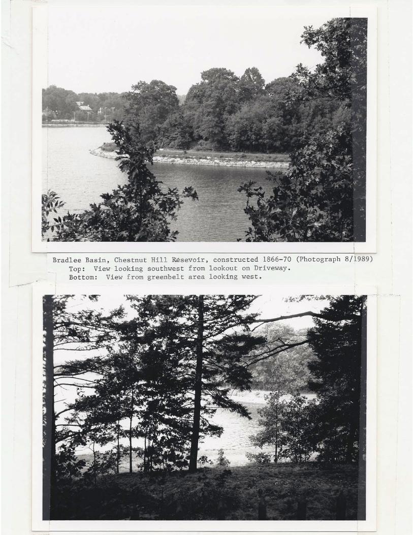
Grounds work for the entire pumping station area was alsodone in 1977 in conjunction with the reservoir basinlandscaping. The lawn, driveway configuration, and treeplanting appear similar to the features visible in an 1890photograph (see following photos). Many of these trees havematured and the driveway and parking areas are in goodcondition.
Effluent Gate House No.2 - Constructed c.1898 to providethe Low Service station with water and increase the flow tothe High Service station, this gate house assumed theoperations of the original Effluent Gate House. It islocated on the embankment directly across Beacon Street fromthe High Service station. It is one-story in height, threewindow bays across, and one deep. High style classicalRenaissance Revival features include the rusticated bandingof the dressed granite ashlar, the iron window grills, andthe low-pitched copper clad hip roof with bronze cheneau.This gate house is currently operational.
9

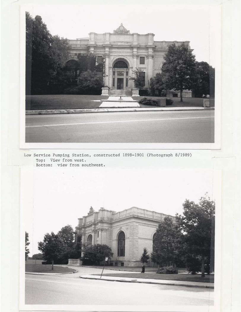
Low Service pumping station - This station is located onthe south side of Beacon Street just east of the High Servicestation. It was built to provide additional low pressureservice to the Boston area when the downtown began to grow.Construction dates from 1898-1901 although the pumps were inservice before the latter date. The Low Service station is aclassical building, basically horizontal in form with asymmetrical main block, rear tower that is low enough toresemble a belvidere, and a wing to the left side of the mainblock. The roofs are flat and encircled with parapets. Thefront and side elevations are clad in light grey finelydressed Indiana limestone ashlar. The foundation and mainstairs are pink Milford granite. Window frames are cast ironwith grill work. The plastic articulation of the main blockand its entrance pavilion facade exemplifies the high styleof Beaux-Arts Classicism.
The station's focal point is the projecting main entrancepavilion with a colossal order of stylized Corninthiancolumns and pilasters. The deep arch soffit is coffered, theorder of the recessed. doorway is Ionic. The parapetpedestals repeat the articulation of the order below. Acentral carved panel reads: Metropolitan Water WorksMDCCCXCVIII. The composition is crowned with a carvedlimestone torch. The main entrance opens directly into theengine room.
On either side of the entrance, the wall area of the mainblock is dominated by a large round-headed window with castiron sash. The classical treatment of the?;fenestration inthe main block includes clathri and fish-scale grill work.The south elevation repeats the design of the single dominantround-headed window. A continuous spring line molding, fullentablature, and parapet unify the design across the facadeand around the corner on the south wall.
The east wing is wide across the front and set back from themain block. The lower roof line helps it recede visually andreflects the floor height here which is lower than in theengine room. The space houses the boiler room in front andthe coal house in the rear, both of which are presently usedfor storage. The facade of the wing has a three-leavedgarage door with the original clathri gone from thesemi-circular transom and the light filled in or paintedover. There are high small windows.
The classical frieze and cornice across the facade and eastelevation of the wing and the continuous parapet aresimplified versions of the main block features.
10

The rear of the Low Service station is red brick. The quoinsare limestone. The parapet brick is different than that ofthe wall surface. The main block has a low, flat roofedextension across it with a higher central entrance; the towerrises from the ground in the angle of the main blocklimestone cladding, the fourth in exposed brick. The towerroof is hipped and red-tiled. The smokestack is yellowbrick, rising from the roof of the coal house.
On the interior, the engine room is finished in buff brickwith red brick trim, polished quartered oak and ash, and agreen slate tile floor. Alterations are evident at the rearbut to a lesser extent than on the High Service station.Abutting the west elevation is a modern wire cage withrusticated concrete side walls which houses mechanicalequipment.
According to the Boston Building Departments document jacketfor the building permit (granted September 27, 1898) thefloor is supported on iron. Plans dated 1898 show the metalfloor and roof framing, entirely clear open spaces in theengine and boiler rooms, a gallery in the boiler room, andiron or steel columns in the coal house. Although theexterior reads as two stories this building has one mainfloor with extremely high ceilings, like the High Servicestation. It contains two operable 20th century turbine pumpsand three obsolete stearn-driven engines. Two of the enginesare vertical triple expansion engines built by the HollyManufacturing Company, dated 1900. The th&rdengine issimilar and is dated 1910.
One plaque in the main entranceway bears the followinginformatiOn regarding the building: "Erected 1899; FredericP. Stearns, Chief Engineer; Dexter Brackett, Engineer ofDistribution Department; Shepley, Rutan & Coolidge,Architects; Metropolitan Water Board - Henry H. Sprague,Wilmot R. Evans, Henry P. Walcott. Another plaque giveswater system information: Metropolitan Water Act recommendedby State Board of Health; Cochituate and Sudbury Systems ofthe City of Boston taken January 1, 1898; Wachusett Systemtaken February 23, 1898 and added to Metropolitan WaterSupply March 7, 1898."
As mentioned for the High Service, re-landscaping was done in1977. At that time a fountain was installed in front of thebuilding; its modern simplicity complements the classicaldesign of the building. There is ivy on the walls of theeast wing. Driveways and parking areas connect the twopumping stations and their ancillary service buildings.
Impressively sited behind an expanse of lawn, the twostations are far enough apart to stand as individualmonuments, and they are well balanced in terms of size andscale. As viewed from Chestnut Hill Driveway scenicoverlook, both relate well to their surroundings.
11

Connection Chamber - Constructed in 1901, this buildingcompliments in style and material, the adjacent High ServicePumping station. This building is constructed of quarryfaced Milford granite with brownstone trim. It has a hippedslate roof with wooden bracketed cornice.
The following, although not major contributing features, arelocated within the complex:
Garage - A one-story building, three window bays across,located between the two stations. It dates from c.1890 andis similar in style to the original gate houses. Window anddoor openings are segmentally-arched, the roof is flat, trimis granite and brick. The building originally served as acarriage house and there is a rear addition of brick withsome windows infilled. The MWRA has ongoing plans to add anaddition to the garage. Plans call for use of identicalmaterials and compatible scale and size. A stable was builtbeside it and later converted to a machine shop. The machineshop burned down in the 1960s.
Pipe yards - The yards consist of four wood frame stuccoedvernacular buildings located at the east end of the site,oriented to form a courtyard facing west which is blacktoppedfor parking. Two of the structures are garage shelters whichflank cottage form buildings, domestic in scale. The pipeyards are well-suited to the site in terms of massing,orientation, date of construction, color, and texture.
A small square concrete block shed is at the south side ofthe high service station. It is non-contributing.
In general, the buildings within the complex appear to be ingood condition. All parts of the property are wellmaintained. The total amount spent in 1977 for High Servicerenovation and landscaping work around the stations andreservoir basin was approximately $1,500,000.
2.3 Photographs:
Attached.
12


3.0 SIGNIFICANCE OF THE PROPERTY
3.1 Summary - The Chestnut Hill reservior and pumping stationsare extremely significant as an unusually intact example of a19th century complex. It combines several of Boston's bestexamples of public architecture, engineering and technology.The complex reflects planning polices which gained importancein the second half of the 19th century and mirrors a growingcivic pride, manifested in public improvements.
The complex was created out of a concern for public healthand safety. The city used the opportunity to construct anumber of high style civic buildings and to create a pastoralpark and drive intended for use by the public. In additionmany noteworthy architects and planners were associated withthe works.
In a comprehensive report on the entire metropolitan watersystem, prepared for the Metropolitan District Commission bythe Cultural Resources Group of Louis Berger & Associates,Inc. titled The water Supply System of Metropolitan Boston1845-1926, the following is written on the significance ofChestnut Hill:
Chestnut Hill is among the most significant, andcertainly the most highly visible, complex within theMetropolitan Water Supply System. It marks theconnection between supply (Cochituate and Sudburyaqueducts) and distribution (high ancb.l:owservicepumping stations) that operated until completion of theCity Tunnel and its extension in the mid~20th century.The constant development and expansion of facilities atChestnut Hill have left a technological legacy ofgravity and pressure conduits, manual and hydraulicgates, and a veritable museum of 19th and early 20thcentury pumping engines, plus modern gas poweredreplacements.
Arranged around Bradlee Basin, the buildings andstructures at Chestnut Hill present a compendium of thewater system's architectural themes. The Greek Revival,first employed on the Cochituate, is represented in theintermediate and effluent gatehouses built in 1868-70.The picturesque eclecticism associated with the"additional supply" developed in the 1870s is portrayedto great effect in George Clough's Sudbury TerminalChamber. The addition by Wheelwright and Haven, is anoutstanding example of the Richardsonian Romanesquestyle, and rightly, an area landmark. Theturn-of-the-century revival of neoclassical styles isvividly illustrated in Shepley, Rutan and Coolidge's lowservice pumping station, a highly successful adaptationof the Beaux Arts style to utilitarian function, and, ona smaller scale, in contemporary low and high servicegatehouse.

Although the Chestnut Hill facility is largely obsolete,the buildings and landscaped grounds remainwell-maintained symbols of the Boston and Metropolitanwater supply systems. Combining functional,technological and architectural importance, ChestnutHill must be considered a pivotal element in the systemas a whole, with the priority given to its future careand conservation.
Historical Overview of the Metropolitan Water System Boston's first inhabitants received their water from cisternsand underground wells. The quality was often poor and theavailability was sporadic. In 1796, the AqueductCorporation, a private company, began delivering water fromJamaica Pond by a system of wooden pipes.
By the mid-19th century, the water supply was inadequate. Itwas thought that the prevention of disease, particularlycholera, was linked with pure water and air. In addition,water was required for fire fighting purposes. In 1846 theCommonwealth granted the City the authority to develop awater supply; John Jervis was hired to design and oversee theconstruction of a reservoir and aqueduct. Jervis utilizedLong Pond in Natick, later renamed Lake Cochituate.
Construction was begun in August, 1846, and the water lineswere connected on October 25, 1848. The opening wascelebrated at a ceremony at the Frog Pond",in the BostonCommon; water was sent through a fountain, 80 feet into theair. The water flowed through the Cochituate Aqueduct to theBrookline Reservoir (still extant on Route 9-Boylston Streetin Brookline). The aqueduct is an egg-shaped, brick conduit,76 inches high, 60 inches wide, and fourteen miles long.This system supplied the city with 18 million gallons per day.
By the late 1870s, Boston needed additional water to serveits rapidly growing population. In 1875-78, the cityexpanded its water supply by utilizing the Sudbury RiverWatershed. This system provided water from four reservoirsin Framingham. Water flowed through the Sudbury Aqueductinto the recently completed Chestnut Hill Reservoir,increasing the city's supply to 69 million gallons per day.
In 1895, the state Legislature established the MetropolitanWater Board (forerunner of the MDC and MWRA) to supply waterto seven cities and six towns in the Boston metropolitanarea. Regional jursidiction was needed to coordinate effortsand keep rates low.
34

The Metropolitan Water Board took control of major portionsof Boston's water supply system including Chestnut Hill. Toexpand the water supply, Sudbury Reservoir in Southboroughwas developed first. Then, a reservoir on the Nashua Riverin Clinton was constructed, now known as the WachusettsReservoir. It began supplying water to the Sudbury system in1908. A network of 400 miles of tunnels, aqueducts and largepipes and over 6000 miles of smaller pipes was laid out; thissystem was in place and functioning by the 1930s. Thesefacilities served metropolitan Boston until construction ofthe Quabbin began in the 1930s.
The Massachusetts Water Board's original plan, developed byFrederic Stearns, the Public Health Board's chief engineer,called for a much larger reservoir to be added in thefuture. It was known that increasing development near theWachusetts Reservoir was detrimental to water quality. In1939, the Quabbin Reservoir was completed. It held 412billion gallons of water, and was filled to capacity by1946. The reservoir now provides water to 2 million people,an average of 300 million gallons per day.
Chestnut Hill Reservoir - The Chestnut Hill Reservoirplayed a major role in the supply of water to theMetropolitan area. It functioned as a supply anddistribution reservoir for over- ~OO years,
The need for a new reservoir, ~o $u~p~em~pt th~ capacity ofthe Brookline reservoir, pad been rl"!peat~dly'brought pej:Orathe Cochituate water Board in ~a65. Tpe ~hestnut Hil~ sltewas chosen because th~ topogrqphy and lqcation providedaccess between thp water source and distribution, with theproper intermediary elevatiop for gravity flow. The CityEngineer, N. Henry Crafts recommended the site; theCommonwealth's authori~atlon WaS was granted in 1865. TheBoard decideq to purchase additiona~ acreage for a secondbasin, the Lawrence Mea40w property then owned by Amos A.Lawrence.
Nineteen separate land transactions were needed in order topurchase the entire site; this was accomplished by 1867 andcost the City $120,000. While Beacon Street had to be movedto a more southerly alignment, it appears that no otherdevelopments were affected. According to John G. Hale's 1830survey, there were no other structures in the area. Thetopography was marsh and meadow land with woodlands andhills.
35

construction of the reservoir basins at Chestnut Hilloccurred between 1866-70. Albert Stanwood was Superintendentof Chestnut Hill reservoir in March 1866. Henry M. Wightman,the Resident Engineer at Chestnut Hill, and his staff of fivewere responsible for detailed surveys and plans. Plans andspecifications for the gate house were made by the office ofthe City Engineer, N. Henry Crafts.
Housing was built on site for the over 400 workers, many wererecent Irish immigrants and veterans returning from the CivilWar. Stables were constructed for teams of horses and oxen;at least fifty animals were utilized. Construction workincluded building the embankment, dam, gate houses andsupport sheds, laying brick drainage sewers and blastingledge rock. Wages were $1.50 per day; a strike in 1867brought them up to $1.75. According to the History of theBoston Water Works from 1868 to 1876, the total cost of landaquisition and construction, in the first decade, was almost2.5 million dollars. However, revenues from city water salesfor the same period were over $565,000.
Lawrence Basin was finished first; water was let in onOctober 27, 1868, the twentieth anniversary of theintroduction of pure water into Boston. The basin was namedfor Amos Lawrence, the first president of the CochituateWater Board and former owner of Lawrence Meadow. Acelebration was held, featuring speeches from Mayor Shurtleffand Nathaniel J. Bradlee, president of the Water Board.Bradlee stated that the completed basinsc:ould provide amonth's supply of water in case of a break in the aqueduct.Also on that day the Highland Standpipe in Roxbury beganoperation. The standpipe was intended to provide highpressure service throughout the city.
Bradlee Basin was completed and operational two years later,on October 25, 1870. This basin was named after Nathaniel J.Bradlee, noted architect and president of the Water Board.An impermeable earth and stone dam separated the two basins.The chamber of a small granite gatehouse, built on the dam,allowed either basin to be emptied for cleaning or repairs.The Cochituate Aqueduct runs underneath the reservoir.
The Chestnut Hill reservoir was originally built with two48-inch mains, one to Brookline reservoir and one directly tothe city. It served for many years as the principalreceiving and distributing reservoir for Boston, supplyingwater by gravity. When the Sudbury aqueduct opened in 1878,it was connected to the Chestnut Hill reservoir as anadditional source through the Terminal Chamber. In the lastthird of the 19th century, Boston's sanitary projects were totake one-third of the total City budget. l
36
When elevated territory was annexed to Boston in the mid1870s, additional high service was needed. At this time, theBoston water system serviced the fifth largest population inthe nation following New York City, Philadelphia, Brooklyn,and chicago. 2 During this period of growth, Chestnut Hillsupplied most of Boston's water; it was chosen as the site ofthe new high service facility. The high service station wasconstructed, in conjunction with the Reservoir on Fisher Hillin Brookline, for this purpose in 1887. The pumps atChestnut Hill were used to fill Fisher Hill reservoir onemile away, at the higher elevation of 241 feet. From therethe water went to Parker Hill Reservoir (now McLaughlan fieldon Mission Hill) at 219 feet elevation or directly todistribution. In 1890, over half of the city required highpressure service in order to be supplied with water fromChestnut Hill, according to The Manual of AmericanWater-Works 1889-90.
In 1897 construction began for an engine room addition toHigh Service. In 1898 construction of the Low Servicepumping station began. The second pumping station atChestnut Hill was needed to fill a "near" storage anddistributing reservoir at Spot Pond (Stoneham) and toincrease low service pressure for a growing downtown. By theend of 1898 the Metropolitan Water Board had increased itstotal storage capacity to 15,755,'00,000 gallons and itsdaily capacity to over 105,000,000 gallons per day.
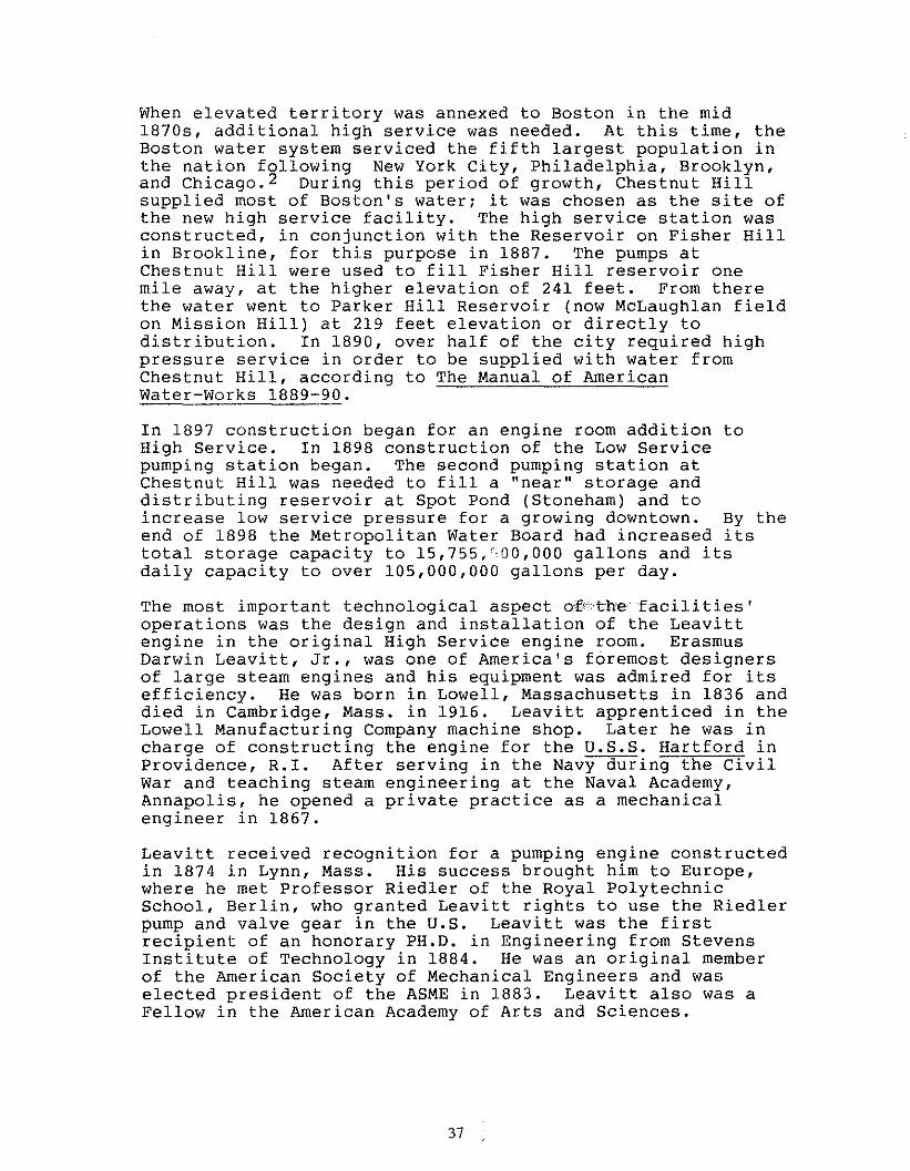
The most important technological aspect O',f\ :cthefacili ties'operations was the design and installation of the Leavittengine in the original High Service engine room. ErasmusDarwin Leavitt, Jr., was one of America's foremost designersof large steam engines and his equipment was admired for itsefficiency. He was born in Lowell, Massachusetts in 1836 anddied in Cambridge, Mass. in 1916. Leavitt apprenticed in theLowell Manufacturing Company machine shop. Later he was incharge of constructing the engine for the U.S.S. Hartford inProvidence, R.I. After serving in the Navy during the CivilWar and teaching steam engineering at the Naval Academy,Annapolis, he opened a private practice as a mechanicalengineer in 1867.
Leavitt received recognition for a pumping engine constructedin 1874 in Lynn, Mass. His success brought him to Europe,where he met Professor Riedler of the Royal PolytechnicSchool, Berlin, who granted Leavitt rights to use the Riedlerpump and valve gear in the U.S. Leavitt was the firstrecipient of an honorary PH.D. in Engineering from StevensInstitute of Technology in 1884. He was an original memberof the American Society of Mechanical Engineers and waselected president of the ASME in 1883. Leavitt also was aFellow in the American Academy of Arts and Sciences.
37

The Chestnut Hill engine is Leavitt's only known survivingwork. The name plate reads: "Boston Water Works, Riedlerpumping Engine, Designed by E.D. Leavitt. Built by N.F.Palmer, Jr. and Co., Quintard Iron Works, New York." Theengine was constructed 1892-94; although the principalcastings were U.S. manufactured, some parts were forged bythe Krupp works in Germany and are so labeled. The Leavittengine was designated a National Historic MechanicalEngineering Landmark by the American Society of MechanicalEngineers in 1973. The Smithsonian Institution displays ascale model of it.
The Chestnut Hill complex served Boston for over 100 years.It began to be phased out in the 1940s with the completion ofthe City Tunnel, directly from the Quabbin Reservoir. Earthfrom the City Tunnel was used to fill the Lawrence Basin,purchased in 1950 by Boston College. The completion of theDorchester Tunnel in the mid-1970s, ending service fromChestnut Hill.
3.2 Summary of architectural significance - Each individualcomponent at Chestnut Hill - the Bradlee Basin, the high andlow service pumping stations, the gate houses, the greenbeltand driveway -- is significant in its own right. As anintact complex, the structures and landscape achieve evengreater significance, and are thought to be the finest andmost intact 19th century complex of the metropolitan watersystem.
Chestnut Hill Driveway and Landscaping - The Chestnut Hillreservoir landscaping, dating from 1866-70, is an excellent,early example of the picturesque style. It is the firstlarge-scale rural park-like setting to be developed by theCity of Boston, even before the Park Commission wasestablished in 1874. The Water Board decided, based largelyon citizen opinion, to create the Driveway in the grandestpossible manner. When completed the Chestnut Hill reservoiroffered Bostonians a beautiful carriage drive or promenade inclean air, out Beacon Street and over the Brighton Road, farfrom the impure city air.
The Chestnut Hill reservoir landscaping was extolled inBoston guidebooks throughout the last quarter of the 19thcentury and the early decades of the 20th century. BostonIllustrated, 1878, carried superlatives in its description:
The Chestnut Hill Reservoir is not only a great benefitto the city in its practical uses, it is also a greatpleasure resort. A magnificent driveway, varying fromsixty to eighty feet in width, surrounds the entirework, and is one of the greatest attractions of thesuburbs of Boston. It is, in fact, the most populardrive in the vicinity.
38

In King's Hand Book of Boston (7th ed. 1885) parks weretitled "The Lungs of the City" and the walks and drives ofChestnut Hill were listed as being "much enjoyed" by itsneighbors who lived in attractive estates on the wooded hilloverlooking the reservoir from the east.
The 1916 publication, A Guide Book to Boston states:
All around the winding outlines of the basin runs atrim driveway, and ..beside it a smooth gravel footpath.On all sides of the lake are symmetrical knolls,covered with forest trees and the greenest of turf.The banks to the water's edge are sodded and borderedwith flowering shrubs; and the stonework, which in oneplace carries the road across a natural chasm, and thegreat natural ledges, are mantled over the clingingvines, and in autumns are aflame with the crimson ofthe Ampelopsis and the Virginia creeper.
The park-like development of Chestnut Hill reservoir wasfirst discussed by the Water Board in 1866. Preliminaryinstructions to the City Engineer, Crafts, were for a road noless than 80 feet in width. Crafts laid out a crushed gravelsurface, as was done for Boston's finer streets. The Boardalso contributed to the aesthetics of the design. NathanielBradlee describes the drive in the 1868 history of Boston'swater works:
••. approximately eighty feet in width; compromisingthat width in cases of fine shade trees, and of ledgeswhich may add picturesqueness ••• The road follows therise and the descent of the ground, and except where itpasses through groves or around rocks, lies upon themargin of the Reservoir, or keeps the water in sight,thus avoiding monotony, and affording beautiful viewsfor the whole distance.
Bradlee, member of the Cochituate Water Board from 1865-1871,first biographer of the City water system, and Water Boardpresident from 1868-71 was most likely the person who addedthe aesthetic principles to Crafts' engineering knowledge inlaying out the Driveway. At the age of seventeen Bradleebegan training in the office of George M. Dexter, a prominentmid-19th century Boston architect. In subsequent yearsBradlee became Dexter's successor and was well-known inBoston for the design of banks, churches, railroad stations,hotels and apartments, office buildings, schools, and blocksof innumberable bow fronts in the South End. Walter Kilhamin Boston After Bulfinch attributed 500 Boston buildings toNathaniel J. Bradlee. Aside from being a prolific Bostonarchitect, Bradlee made a civic contribution as a member ofthe Water Board. He earned the honor of having the largerbasin at Chestnut Hill reservoir named after him.
39

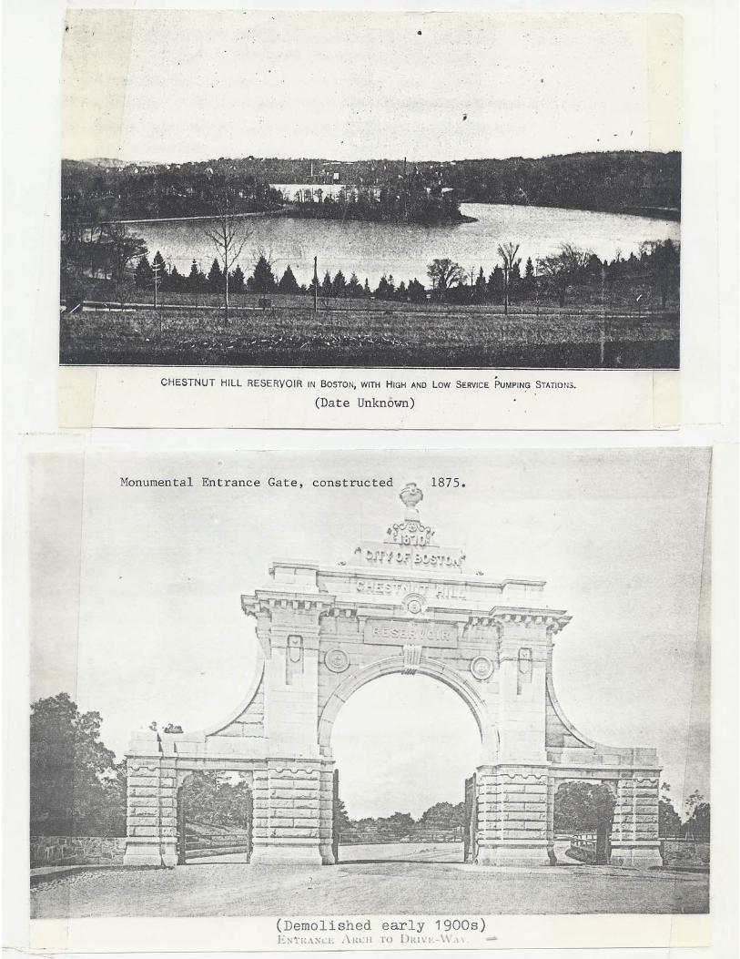
Construction of the Driveway was expected to cost $125,000 -the final cost was over $200,000. The crowning element was atriumphal granite entrance arch, erected in 1870 tocommemorate the water works. In the early 1900s the arch wasremoved for street widening.
According to Cynthia Zaitsevsky's Frederick Law Olmsted andthe Boston Park System, Chestnut Hill Driveway was includedin a 1887 plan to link the Emerald Necklace with other parksin Boston including Chestnut Hill Reservoir and Marine Parkin South Boston. The plan was titled, in part " •.• PublicWays adapted to Pleasure Travel." Olmsted had designed andimproved sections of Commonwealth Avenue in Brighton andBeacon Street in Brookline, the two major roads leading toChestnut Hills. This created a loop with the previouslylaid-out Chestnut Hill Driveway; Olmsted called this theChestnut Hill Circuit.
High Service Station - The first Chestnut Hill pumpingstation is an excellent example of the RichardsonianRomanesque style. It is considered one of the finest works ofBoston architect, Arthur Vinal.
The High Service station was built in 1887-1888. Vinal wasone of many admiring architects who worked in the style whichRichardson has been credited with creating. Richardson'sgenius lay in his handling of common late 19th centuryeclectic idioms with a powerful simplicity and coherence.Whereas Victorian designs abandoned focus in favor of surfacerichness, Richardson made beautiful carvirrgand lush surfacetreatment subordinate to mass, volume, and scale. Largepublic buildings became the Richardsonian hallmark, and inthe late 1880s many cities built libraries, city halls,schools, post offices, and churches in the style.
The Chestnut Hill High Service station is bold in its use ofgranite and freestone in cathedral-like grandeur for astrictly utilitarian building. The broad, open site iswell-suited to Richardsonian massing and horizontality. TheWheelwright & Haven addition of 1887-89 is sensitive to theoriginal design in terms of form and surface treatment. TheChestnut Hill pumping station is a very lively design; thedetails in the tower are particularly striking, and the boldexterior is well-suited to the two-story steam engines whichit was built to house.
According to a 1910 publication by the Metropolitan WaterBoard, the total expenditure made for the original pumpingstation and addition was approximately $265,000. Contractorsfor the original construction of 1887-88 included Collins &Ham, builders; Donahue Bros., masonry; Jeremiah Carew,free-stone; Edward Marley & Bros., copper work; John McLaren,carpentry; Walworth Manufacturing Co., steam pipes; Cofrode &Saylor, iron roofs; and George R. Clarke & Co., tile work.C.A. Dodge & Co. was the contractor for the 1897-99 addition,and the steel work was executed by Edward Kendall & Sons.
40
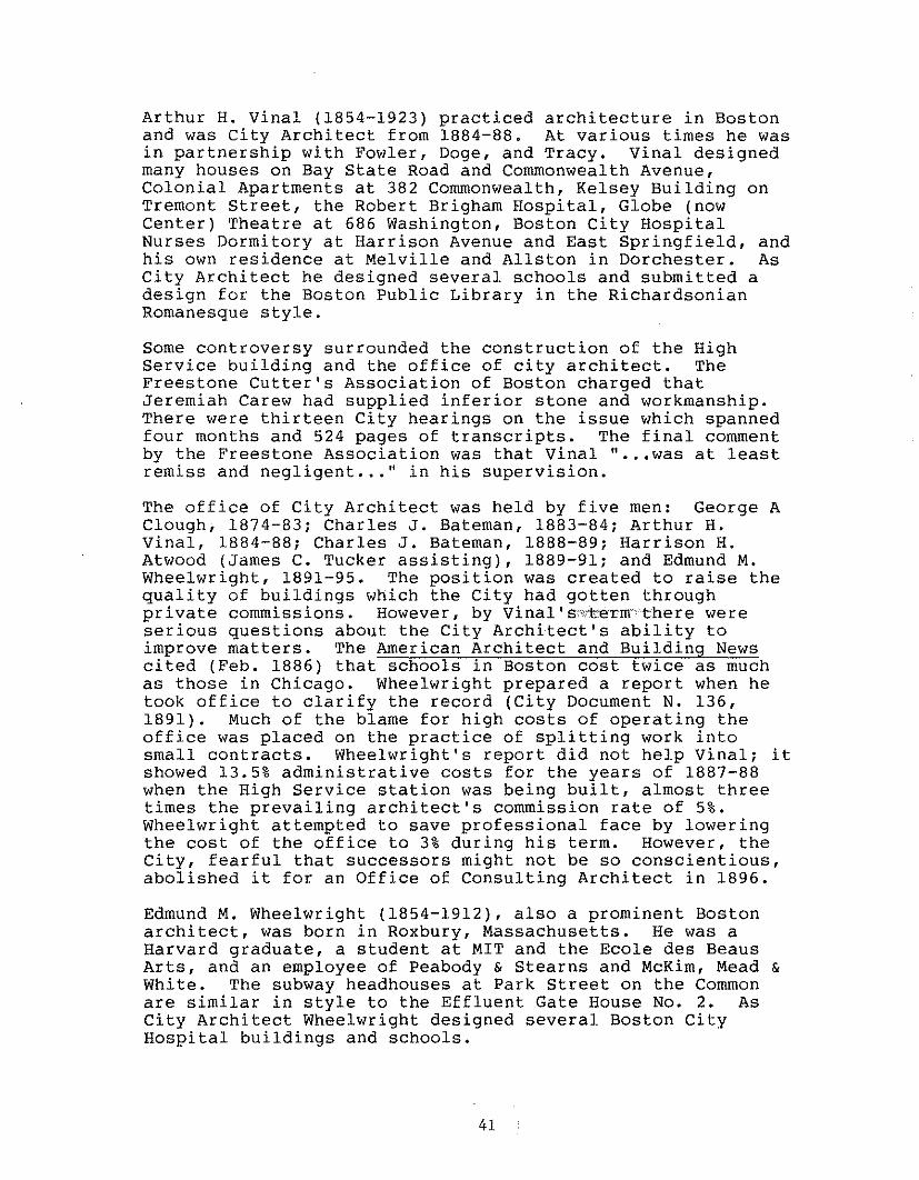
Arthur H. Vinal (1854-1923) practiced architecture in Bostonand was City Architect from 1884-88. At various times he wasin partnership with Fowler, Doge, and Tracy. Vinal designedmany houses on Bay state Road and Commonwealth Avenue,Colonial Apartments at 382 Commonwealth, Kelsey Building onTremont Street, the Robert Brigham Hospital, Globe (nowCenter) Theatre at 686 Washington, Boston City HospitalNurses Dormitory at Harrison Avenue and East Springfield, andhis own residence at Melville and Allston in Dorchester. AsCity Architect he designed several schools and submitted adesign for the Boston Public Library in the RichardsonianRomanesque style.
Some controversy surrounded the construction of the HighService building and the office of city architect. TheFreestone Cutter's Association of Boston charged thatJeremiah Carew had supplied inferior stone and workmanship.There were thirteen City hearings on the issue which spannedfour months and 524 pages of transcripts. The final commentby the Freestone Association was that Vinal " •.• was at leastremiss and negligent ... " in his supervision.
The office of City Architect was held by five men: George AClough, 1874-83; Charles J. Bateman, 1883-84; Arthur H.Vinal, 1884-88; Charles J. Bateman, 1888-89; Harrison H.Atwood (James C. Tucker assisting), 1889-91; and Edmund M.Wheelwright, 1891-95. The position was created to raise thequality of buildings which the City had gotten throughprivate commissions. However, by Vinal's""teTmthere wereserious questions about the City Architect's ability toimprove matters. The American Architect and Building Newscited (Feb. 1886) that schools in Boston cost twice as muchas those in Chicago. Wheelwright prepared a report when hetook office to clarify the record (City Document N. 136,1891). Much of the blame for high costs of operating theoffice was placed on the practice of splitting work intosmall contracts. Wheelwright's report did not help Vinal; itshowed 13.5% administrative costs for the years of 1887-88when the High Service station was being built, almost threetimes the prevailing architect's commission rate of 5%.Wheelwright attempted to save professional face by loweringthe cost of the office to 3% during his term. However, theCity, fearful that successors might not be so conscientious,abolished it for an Office of Consulting Architect in 1896.
Edmund M. Wheelwright (1854-1912), also a prominent Bostonarchitect, was born in Roxbury, Massachusetts. He was aHarvard graduate, a student at MIT and the Ecole des BeausArts, and an employee of Peabody & Stearns and McKim, Mead &White. The subway headhouses at Park Street on the Commonare similar in style to the Effluent Gate House No.2. AsCity Architect Wheelwright designed several Boston CityHospital buildings and schools.
41

The partnership with Parkman B. Haven (1853-1943) began in1889; a second partner, Edward A. Hoyt, joined the firm inthe 1890s. The firm prepared plans for several large publicbuildings including Horticultural Hall, New EnglandConservatory of Music, the Opera House of 1908, Jordan Hall,and the State Historical Building in the Fenway. Wheelwrightwas a consulting architect to GUy Lowell on the design of theMuseum of Fine Arts. He died in Dedham after having spenttwo years in a sanitarium in Connecticut as the result of anervous breakdown attributed to overwork. Wheelwright waselected a fellow of the American Institute of Architects in1901. He authored School Architecture (1901) and articlesfor professional magazines.
Low Service pumping station - This building is one ofBoston's very few public buildings designed in the Beaux ArtsClassical style. It is also significant as a work designedby the nationally prominent firm of Shepley, Rutan &Coolidge. The Low Service station was constructed as partof the massive expansion plan initiated by the MetropolitanWater Board. It's pumps provided water to Spot Pond,Stoneham and directly to the city. In addition to housingpumps and engines, the tower contained an overflow tank whichcould hold 31,000 gallons of water. Coal for the engines wasbrought directly from a siding of the Boston and Albanyrailroad tracks at the rear of the station.
Beaux-Arts Classicalism takes its name from the Academy desBeaux Arts in Paris. In the last quarter ,'of"the 19th centurymany American architectural students went to Paris andreturned to the U.S. to lead successful careers. The stylecalled Beaux-Arts Classicism is set apart from theNeo-Classical Revival and the Renaissance Revival styles withwhich it was contemporaneous. Characteristic elements of thestyle include paired or even clustered columns, deeplysculptural ornament and a high parapet or attic. Windows maybe enframed by free-standing columns, balustraded sill, andpedimented entablature on top. It is a style almostexclusively used for civic architecture.
The Low Service station exemplifies the shift in Americanarchitecture since the High Service station had been built.High style public design was classical; Victorian colors andforms were abandoned for symmetry and classical lines.
The classicalism of the turn of the century used all themodern technology available in its structural underpinnings.Even though the exteriors were faced with stone and made toappear to be masonary construction, the buildings usuallycontained steel or reinforced concrete. The Chestnut HillLow Service station is no exception. The foundation sits onprevious landfill with boulders, rocks, and earth from thereservoir basins. Plans show iron plates below the threeoriginal engines and a metal tank in the tower.
42

In the event that emergency service is required, two 1974,solar gas turbine engines, housed in the low servicebuilding, are still functional.
The Low Service station was built by Norcross Brothers,contractors for many H.H. Richardson buildings and later forShepley, Rutan & Coolidge. The amount of the contract was$182,659.50.*
Richardson's successor firm, Shepley, Rutan & Coolidge,designed many noteworthy buildings throughout the UnitedStates, such as the Lionberger, Tiffany, and Mallinkridtbuildings in St. Louis; the original Stanford Universitycampus; the Art Institute and the Chicago Public Library;Vassar Chapel; Government Hospital for the Insane, WashingtonD.C; Brown University Library; and buildings at theUniversity of Chicago. The Ames Building, a Shepley, Rutan &Coolidge design, was the highest building in Boston when itwas completed in 1892 -- the firm located their offices onthe top floor. Important Boston area commissions includeSouth Terminal Station, Harvard Medical School, the EastonBuildings on State Street, the Weld Building on FederalStreet, the First Parish Church in Brookline, the EpiscopalTheological School Library in Cambridge, many houses, thePublic Library in New London, Conn., and the FirstCongressional Church in Fall River, Mass.
Charles Rutan (1851-1914) was born in Newark, N.J., andtrained in Boston in the office of Gambrill & Richardson.George Shepley (1860-1903) was born in St;\Iiouis and educatedthere at Washington University and at MIT. He marriedRichardson's oldest daughter and died an untimely death atthe age of 43. Charles Allerton Coolidge (1858-1936) wasborn in Boston and educated at Harvard and MIT. His laterpartners inCluded George C. Shattuck from 1914-1922, and alsoCoolidge, Shepley (Henry R., son of George), Bulfinch, andAbbott in 1925. Coolidge was married to George Shepley'ssister. He was elected a Fellow of the AlA in 1891, hereceived an honorary Doctor of Arts degree from Harvard in1906, he was president of the Boston Society of Architects,and he held many public and honorary positions in the courseof his long career.
Effluent Gate House No. 1 This is the first structurebuilt in the Chestnut Hill Reservoir complex. Constructedbetween 1869-70, this gate house contained the major controlgates for the Chestnut Hill Reservoir. The structure wasconstructed to house four pipes, although only two wereused. In 1874, two hydraulic gates were installed.
*Given the prolific work of the Olmsted firm in and around Boston atthe time of the construction of the Low Service building, an attemptwas made to investigate the possibility that landscape work by Olmstedmay have been done at Chestnut Hill. Information derived from theLibrary of Congress Manuscripts Department, holders of the Olmstedfirm's papers, has revealed that the firm's only involvement inprojects at Chestnut Hill was an instance of the recommendation ofpossible sub-formen in May, 1904 (work related to the construction ofthe Low Service building).
43

Effluent Gate House No. 2 - This gate house was built in1900-01 as a major component of Metropolitan water Board'sexpansion plans, to supply water to the low and high servicepumping stations. The Renaissance Revival design is byWheelwright & Haven, who also designed the High Serviceaddition. It was built by John S. Jacob & Sons for anestimated cost of $10,000. The structure houses threehydraulic gates which control three 60" mains, beneath a castiron floor.
Connection Chamber - This structure, adjacent to the HighService station, was used to take water from the CochituateAqueduct by a four foot main, to the High Service station.This simple, Milford granite structure, was built by theNorcross Brothers.
Buildings and structures with contributing significance The puddingstone garage is architecturally significant interms of its relationship to the property as a whole.
Contributing background buildings and structures - The fourPipe Yard buildings, while not significant individually, arepart of the completeness of the complex; they do not detractarchitecturally from the whole composition.
44
3.3 Relationship to the criteria for Landmark designation
The Chestnut Hill Reservoir and Pumping Stations meet allfour criteria for designation as a Landmark, as establishedin Section 4 of Chapter 772 of the Acts of 1975, as amended.They are:
--inclusion in National Register of Historic Places asprovided in the National Historic Preservation Act of 1966;(voted eligible by the Massachusetts Historical Commission in1977)
--structures, sites, objects, man-made or natural, at whichevents occurred that have made an outstanding contributionto, and are identified prominently with, or which bestrepresent some important aspect of the cultural, political,economic, military or social history of the city,commonwealth, the New England Region or the nation.
--structures, sites, objects, man-made or natural, associatedsignificantly with the lives of outstanding historicpersonages;
--structures, sites, objects, man-made or natural,representative of elements of architectural or landscapedesign or craftsmanship which embody distinctivecharacteristics of a type inherently valuable for study, of aperiod, style or method of construction or development, or anotable work of an architect, landscape architect, designer,or builder whose work influenced the development of the city,the commonwealth, the New England region or the nation.
45

4.0 ECONOMIC STATUS
4.1 Current assessed value and property tax - Assessor's parcelnumber 2472 which encompasses the Bradlee reservoir basin anda portion of the driveway is 4,804,748 square feet; it isassessed at $21,865,000. Assessor's parcel number 2439 is345,780 square feet and contains the High Service and LowService pumping stations, the two stone kiosks, the stonegarage, the Pipe Yards buildings, landscaped grounds, parkingarea and driveways. It is assessed at $1,440,000. Theincluded portion of assessor's parcel number 2442-5(approximately 9/10 of the total parcel) contains a portionof the Driveway and all of the parkway along the northernboundary of the property. The land area is approximately688,030 square feet. The assessed value for this City-ownedland is $3,551,000. Total assessed value of the parcelsabove as listed is $26,856,000. All three parcels, two ownedby the MDC and one owned by the City, are tax exempt.
4.2 Current ownership, occupancy and status - Parcel number 2472and 2493 containing the Bradlee Basin and pumping stationsare owned by the Metropolitan District Commission,Commonwealth of Massachusetts, and are under the control andmanagement of the Massachusetts Water Resources Authority,Commonwealth of Massachusetts. Parcel number 2442-5 is ownedby the City of Boston, Park Department and was leased to theMDC for 99 years, until November 20, 2077. The MWRA isdeveloping a use plan for the Pumping station and itsgrounds. The MWRA is proceeding with the' ,'!'ev:iewofprospective firms for the development of the facility. Afterthe selection process is completed, the MWRA expects a designby January of 1990. The proposed plan is discussed furtherin the planning section of this report.
47

5.0 PLANNING CONTEXT
5.1 Background - The Metropolitan District Commission WaterDivision had developed plans for the Chestnut Hill facilitybefore transfer of operations to the Massachusetts WaterResources Authority took place in July, 1985. The MDC'splans for reuse of the Low Service building included movingits archives into an adapted space, installing a generalWater Division operations and control center, and addinganother turbine to the present pumping equipment.
The MDC presently owns the Chestnut Hill property (except forparcel 2442-5 which is owned by the City of Boston and isleased to the MDC), and the MWRA operates and manages thefacility. Beginning in July, 1985, the MWRA received controlof the facility, and a memorandum of understanding createdlater set the specifications of the MDC-MWRA agreement. Itis the MWRA which has planning and developmental control overthe property.
5.2 Current planning issues directly or. indirectly affecting theproperty The Massachusetts Water Resource Authority hasdeveloped a plan for use of the Chestnut Hill facility andthe summary of the project as presented here is from theScope of Services Project Summary, an MWRA planning documentfor the selection of a firm for the project. The currentplans of the MWRA propose the use of the two pumpingstations, the garage, the pipe yard buildings, and theircommon grounds. The facility is no longe·r"used for pumping,although two pumps in the Low service building and one in thehigh service building are operable and will be retained foremergency use. The "Scope of Services" describes in its"project Summary:"
The MWRA project consists of the rehabilitation of allthe usable space within the low and high servicebuildings and rehabilitation of the existing pipe yardbuildings and/or construction of new buildings at theChestnut Hill site to consolidate several WaterworksDivision functions. It is anticipated the site willhouse Waterworks Division's Metropolitan Operationsstaff, a laboratory, trade shops, archives, parking andstorehouse facilities, and the new operations center forthe central monitoring system.
The intended uses of the buildings on the Chestnut HillReservoir as stated in the Scope of Services "ProjectSummary" are as follows.
1. High Service Buildinga. museum, including "hall of machines" and publicdisplay areas (not part of this project)
49

(1. con't)b. office area, enclosed and open typing andconference rooms, auditorium, drafting area and recordcenterc. archives
2. Garagea. operations center and central monitoring system (notpart of this project)
3. Low Service Buildinga. laboratoryb. office areasc. support areas, such as lunchroom, lockers, showersand toilets for men and women, work area for on-the-roadstaff to fill out reports, area for receiving uniforms
4. Pipe Yard Buildinga. trade shops for carpentry, electrical, machine,plumbing and painting activitiesb. storehousingc. garage space
5. Groundsa. parking for the Authority's vehicles and heavyequipmentb. parking areas for staff and visitorsc. pipe stock storage
The "Project Summary" makes some other specificationsregarding the use of these buildings. It states that theproposed museum for the High Service Building is planned tobe a combined effort of the MWRA and various privateinterests; and although the museum design is not a part ofthis contract, the museum space must be considered in theoverall design. The "Summary" also states that anyrehabilitation of the High Service Building structure itself,the roof repair in particular, will be done as a part of thisproject. The museum will occupy approximately 13,000 squarefeet and will consist of various display areas.
The planned laboratory for the Low Service building is to bean expanded version of the MWRA laboratory at Somerville tomeet the new requirements of the 1986 Amendments to the SafeDrinking water Act. The design should take intoconsideration specialized needs of a water quality laboratorysuch as ventilation, exhaust, and room pressure requirementsfor trace analysis.
The trade shops, maintenance facility, equipment housing andstorage requirements are generally expected to be thecombination of present operations at the Authority'sfacilities located at Glenwood Yard, Mystic Shops, andRutherford Avenue (electronic maintenance personnel only).The MWRA's goal is to relocate as much of the OperationsDepartment to this site as is possible within siteconstraints.
50

The facilities at Chestnut Hill are expected to accommodatean aggregate staff of approximately 175 persons, with about50 to 75 stationed at Chestnut Hill and the others on theroad and reporting in and out. The Scope of Services statesthat the consultant must take into account the surroundingenvironment for architectural and landscape design. TheScope also states that there are emergency pumps in thebasements of both the Low and High Service buildings and theconsultant must identify provisions for keeping these pumpsintact during the construction phase.
The MWRA is aware of historic preservation considerationsregarding the property. The Scope of Work "project Summary"states"
The buildings, surroundings, and select pieces ofpumping equipment have been identified as beingarchitecturally and historically significant. Everyeffort must be made to preserve this heritage and alldesign must conform to the guidelines of the Historicaland Landmark Commissions.
The MWRA's Scope of Services states in the "PreliminaryDesign Phase" that the consultant must "determine requiredguidelines by State, Federal and other regulatory agenciesand Landmark/Historical Commissions applicable to thefacility, and coordinate the project with these agencies andcommissions." In the "project Management for Preliminary &Final Design Phases" it is stated that the"consultant"prepare for and attend meetings with regulatory agencies andHistoric/Landmark Commissions and neighborhood groups."
In 1983, the MDC received a Survey and Planning Grant fromthe Massachusetts Historical Commission to conduct anhistoric inventory of Metropolitan Boston's water supplysystem. The survey identified over 120 structures including11 in Boston, 8 which are at Chestnut Hill. A MultipleResource Area Nomination to the National Register of HistoricPlaces has been completed. It is expected that theMassachusetts Historical Commission will hear the nominationin Fall, 1989. If accepted by the Massachusetts HistoricalCommission, and then the Department of the Interior, theChestnut Hill Complex would be listed on the NationalRegister of Historic Places.
51

5.3 Relationship to current zoning - the Chestnut Hill reservoirand pumping station property is divided into several zoningclassifications involving housing. They consist of S-.3single family; R-.5 two family; H-l, H-2, and H-3 apartmentzones. The adjacent properties of the MDC Cleveland Circlepark/recreation area and the Cassidy Playground/Chestnut HillPark area are zoned H-2 and S-.3 respectively.
Other planning issues deal with the Chestnut Hill facility orhave the potential to effect it. The BRA's Allston-BrightonIterim Planning Overlay District (IPOD), effective August 18,1987, states in its statement of purpose the desire "toprevent overcrowding of land [and] to preserve, enhance, andcreate open space." Under the IPOD's "Open Space Plan," theAllston-Brighton Planning and Zoning Advisory Committee(PZAC) is considering designating the Chestnut Hill Reservoiras open space. The plan is an attempt to recognize"historic, geographic and functional links to historicAllston-Brighton, to activity modes within Allston-Brighton,and to the open space and park system of Boston." Fullconsideration of this open space designation would take placein the fall of 1989. If approved, designation would place onthe property specific land use restrictions defined by theclassification given the property by the PZAC (Le.,parkland, recreation, urban wild, etc.).
52

6.0 ALTERNATIVE APPROACHES
6.1 Alternatives:
Alternatives open to the Boston Landmarks Commission includedesignation of the entire complex as a landmark, or anycomponent(s) within the complex. The nature of the property,a cohesive unit in terms of development history, commonpurpose, ownership and/or jurisdiction, suggests designationas a Landmark. The commission may also designate part of thesite, within 1200 feet of a Landmark, as a protection area.
The Commission retains the option to not designate specificcomponents or the entire complex. Not designating elementsas a Landmark would mean that the City could offer noprotection or guidance under future owners.
Landmark designation under Chapter 772 would require thereview of physical changes to the exterior of the buildingsand specified landscape elements in accordance with thestandards and criteria adopted as part of the designation.
An alternative would be the inclusion of the properties onthe National Register of Historic Places. The property wasvoted eligible for listing on the National Register in 1977.If accepted, listing on the Register would offer a limiteddegree of protection against federal or state undertakings.
6.2 Impact of alternatives:
Landmark designation under Chapter 772 would require thereview of physical changes to the exterior of the buildings,included in the designation, as well as the reservoir groundsin accordance with the standards and criteria adopted as partof the designation. It would not, however, affect the use ortreatment of the interior of the buildings.
Listing on the National Register of Historic Places wouldprovide protection from federal, federally-licensed orfederally-assisted actions undertaken by Section 106 Reviewprocess. Similar protection from state-sponsored activitiesis achieved by the concurrent listings of all NationalRegister properties to the State Register of Historic Placesunder Chapter 254, General Laws of Massachusetts.
53

7.0 RECOMMENDATIONS
7.1 Recommended action - The staff of the Boston LandmarksCommission recommends that the Chestnut hill reservoir andpumping stations complex be designated a Landmark underChapter 772 of the Acts of 1975, as amended.
The boundaries of the proposed designation are thefollowing: all of Parcel 2439; the Bradlee Basin, definedon the east and south sides by the boundary of parcel 2472(starting at the intersection with Commonwealth Avenue) andon the north and west sides by the Chestnut Hill Driveway;Chestnut Hill Driveway, from the intersection at BeaconStreet, proceeding north along the fenceline bordering theBoston College playing field to a line extending across theDriveway along the eastern fenceline of Evergreen Cemetery,and the remaining portion of parcel 2442-5 to the north andeast.
See attached map.
55


8.0 GENERAL STANDARDS & CRITERIA
8.1 Introductory Statement on Standards and Criteria to be usedin Evaluating Applications for Certificates
Per sections 4, 5, 6, 7, and 8 of the enabling statute(Chapter 772 of the Acts of the 1975 of the Commonwealth ofMassachusetts) Standards and Criteria must be adopted foreach Landmark Designation which shall be applied by theCommission in evaluating proposed changes to the property.Before a Certificate of Design Approval or Certificate ofExemption can be issued for such changes, the changes mustbe reviewed by the Commission with regard to theirconformance to the purposes of the statute.
The Standards and Criteria established thus note thosefeatures which must be conserved and/or enhanced to maintainthe viability of the Landmark Designation.
The intent of these guidelines is to help local officials,designers, and individual property owners to identify theCharacteristics that have led to designation, and thus toidentify the limitation to the changes that can be made tothem. It should be emphasized that conformance to theStandards and Criteria alone does not necessarily insureapproval, nor are they absolute, but any request forvariance from them must demonstrate the reasons for, andadvantages gained by, such variance. The Commission'sCertificate of Design Approval is only granted after carefulreview of each application and public hearing, in accordancewith the statute.
As intended by the statute a wide variety of buildings andfeatures are included within the area open to LandmarkDesignation, and an equally wide range exists in thelatitude allowed for change. Some properties of trulyexceptional architectural and/or historical value willpermit only the most minor modifications, while for someothers the Commission encourages changes and additions witha contemporary approach, consistent with the properties'existing features and changed uses.
In general, the intent of the Standards and Criteria is topreserve existing qualities that cause designation of aproperty; however, .j.n some cases they have been sostructured as to encourage the removal of additions thathave lessened the integrity of the property.
It is recognized that changes will be required in designatedproperties for a wide variety of reasons, not all of whichare under the complete control of the Commission or theowners. Primary examples are:
57

(a) Building code conformance and safetyrequirements.
(b) Changes necessitated by the introduction ofmodern mechanical and electrical systems.
(c) Changes due to proposed new uses of a property.
The response to these requirements may, in some cases,present conflicts with the Standards and Criteria for aparticular property. The Commission's evaluation of anapplication will be based upon the degree to which suchchanges are in harmony with the character of the property.
In some cases, priorities have been assigned within theStandards and Criteria as an aid to property owners inidentifying the most critical design features.
The Standards and Criteria have been divided into twolevels: (1) those general ones that are common to almost alllandmark designations (subdivided into categories forbuildings and landscape features); and (2) those specificones that apply to each particular property that isdesignated. In every case the Specific Standard andCriteria for a particular property shall take precedenceover the General ones if there is a conflict.
58

8.2 GENERAL STANDARDS AND CRITERIA
A. APPROACH
1. The design approach to the property should begin withthe premise that the features of historical andarchitectural significance described within the StudyReport must be preserved. In general this willminimize the exterior alterations that will beallowed.
2. Changes to the property and its environment whichhave taken place in the course of time are evidenceof the history of the property and the neighborhood.These changes to the property may have developedsignificance in their own right, and thissignificance should be recognized and respected.("Later integral features" shall be the term used toconvey this concept.)
3. Deteriorated material or architectural features,whenever possible, should be repaired rather thanreplaced or removed.
4. When replacement of architectural features isnecessary it should be based on physical ordocumentary evidence of original or later integralfeatures.
5. New materials should, whenever possible, match thematerial being replaced in physical properties,design, color texture and other visual qualities.The use of imitation replacement materials isgenerally discouraged.
6. New additions or alterations should not disrupt theessential form and integrity of the property andshould be compatible with the size, scale, color,material and character of the property and itsenvironment.
7. Contemporary design is encouraged for new additions;thus, they must not necessarily be imitative of anearlier style or period.
8. New additions or alterations should be done in such away that if they were to be removed in the future,the essential form and integrity of the historicproperty would be unimpaired.
9. Priority shall be given to those portions of theproperty which are visible from public ways or whichit can be reasonably inferred may be in the future.
59

10. Color will be considered as part of specificstandards and criteria that apply to a particularproperty.
B. EXTERIOR WALLS
I. MASONRY
1. Retain whenever possible, original masonry and mortar.
2. Duplicate original mortar in composition, color,texture, joint size, joint profile and method ofapplication.
3. Repair and replace deteriorated masonry with materialwhich matches as closely as possible.
4. When necessary to clean masonry, use gentlest methodpossible. Do not sandblast. Doing so changes thevisual quality of the material and acceleratesdeterioration. Lest patches should always be carriedout well in advance of cleaning (including exposureto all seasons if possible).
5. Avoid applying waterproofing or water repellentcoating to masonry, unless required to solve aspecific problem. Such coatings can acceleratedeterioration.
6. In general, do not paint masonry surfaces. Paintingmasonry surfaces will be considered only when thereis documentary evidence that this treatment was usedat some point in the history of the property.
II. NON-MASONRY
1. Retain and repair original or later integral materialwhenever possible.
2. Retain and repair, when necessary, deterioratedmaterial with material that matches.
C. ROOFS
1. Preserve the integrity of the original or laterintegral roof shape.
2. Retain original roof covering whenever possible.
3. Whenever possible, replace deteriorated roof coveringwith material which matches the old in composition,size, shape, color, texture, and installation detail.
4. Preserve architectural features which give the roofits character, such as cornices, gutters, ironfilligree, cupolas, dormers, brackets.
60

D. WINDOWS AND DOORS
1. Retain original and later integral door and windowopenings where they exist. Do not enlarge or reducedoor and window openings for the purpose of fittingstock window sash or doors, or air conditioners.
2. Whenever possible, repair and retain original orlater integral window elements such as sash, lintels,sills, architraves, glass, shutters and otherdecorations and hardware. When replacement ofmaterials or elements is necessary, it should bebased on physical or documentary evidence.
3. On some properties consideration will be given tochanging from the original window details to otherexpressions such as to a minimal anonymous treatmentby the use of a single light, when consideration ofcost, energy conservation or appropriateness overridethe desire for historical accuracy. In such cases,consideration must be given to the resulting effecton the interior as well as the exterior of thebuilding.
E. PORCHES, STEPS AND EXTERIOR ARCHITECTURAL ELEMENTS
1. Retain and repair porches and steps that are originalor later integral features including such items asrailings, balusters, columns, posts, brackets, roofs,ironwork, benches, fountains, statues and decorativeitems.
F. SIGNS, MARQUEES AND AWNINGS
1. Signs, marquees and awnings integral to the buildingornamentation or architectural detailing shall beretained where necessary.
2. New signs, marquees and awnings shall not detractfrom the essential form of the building nor obscureits architectural features.
3. New signs, marquees, awnings shall be of a size andmaterial compatible with the building and its currentuse.
4. Signs, marquees and awnings applied to the buildingshall be applied in such a way that they could beremoved without damaging the building.
5. All signs added to the building shall be part of onesystem of design, or reflect a design conceptappropriate to the communication intent.
61

6. Lettering forms or typeface will be evaluated for thespecific use intended, but generally shall either becontemporary or relate to the period of the buildingor its later integral features.
7. Lighting of signs will be evaluated for the specificuse intended, but generally illumination of a signshall not dominate illumination of the building.
8. The foregoing not withstanding, signs are viewed asthe most appropriate vehicle for imaginative andcreative expression, especially in structures beingreused for purpose different from the original, andit is not the Commission's intent to stifle acreative approach to signage.
G. PENTHOUSES
1. The objective of preserving the integrity of theoriginal or later integral roof shape shall providethe basic criteria in judging whether a penthouse canbe added to a roof. Height of a building, prominenceof roof form, and visibility shall govern whether apenthouse will be approved.
2. Minimizing or eliminating the visual impact of thepenthouse is the general objective and the followingguidelines shall be followed:
(a) Location shall be selected where the penthouseis not visible from the street or adjacentbuildings; setbacks shall be utilized.
(b) Overall height or other dimensions shall be keptto a point where the penthouse is not seen fromthe street or adjacent buildings.
(c) Exterior treatment shall relate to thematerials, color and texture of the building orto other materials integral to the period andcharacter of the building, typically used forappendages.
(d) Openings in a penthouse shall relate to thebuilding in proportion, type and size ofopening, wherever visually apparent.
H. LANDSCAPE FEATURES
1. The general intent is to preserve the existing orlater integral landscape features that enhance thelandmark property.
62

2. It is recognized that often the environmentsurrounding the property has character, scale andstreet pattern quite different from that existingwhen the building was constructed. Thus, changesmust frequently be made to accommodate the newcondition, and the landscape treatment can be seen asa transition feature between the landmark and its newsurroundings.
3. The existing landforms of the site shall not bealtered unless shown to be necessary for maintenanceof the landmark or site. Additional landforms shallonly be considered if they will not obscure theexterior of the landmark.
4. Original layout and materials of the walks, steps,and paved areas should be maintained. Considerationwill be given to alterations if it can be shown thatbetter site circulation is necessary and that thealterations will improve this without altering theintegrity of the landmark.
5. Existing healthy plant materials should be maintainedas long as possible. New plant materials should beadded on a schedule that will assure a continuity inthe original landscape design and its lateradaptations.
6. Maintenance of, removal of, and additions to plantmaterials should consider maintaining existing vistasof the landmark.
I. EXTERIOR LIGHTING
1. There are three aspects of lighting related to theexterior of the building:
(a) Lighting fixtures as appurtenances to the building orelements or architectural ornamentation.
(b) Quality of illumination on building exterior.
(c) Interior lighting as seen from the exterior.
2. Wherever integral to the building, original lightingfixtures shall be retained. Supplementaryillumination may be added where appropriate to thecurrent use of the building.
3. New lighting shall conform to any of the followingapproaches as appropriate to the building and to thecurrent or projected use:
63

(a) Accurate representation of the original period,based on physical or documentary evidence.
(b) Retention or restoration of fixtures which datefrom an interim installation and which areconsidered to be appropriate to the building anduse.
(c) New lighting fixtures which are contemporary indesign and which illuminate the exterior of thebuilding in a way which renders it visible atnight and compatible with its environment.
4. If a fixture is to be replaced, the new exteriorlighting shall be located where intended in theoriginal design. If supplementary lighting is added,the new location shall fulfill the functional intentof the current use without obscuring the buildingform or architectural detailing.
5. Interior lighting shall only be reviewed when itscharacter has a significant effect on the exterior ofthe building; that is, when the view of theilluminated fixtures themselves, or the quality andcolor of the light they produce, is clearly visiblethrough the exterior fenestration.
J. REMOVAL OF LATER ADDITIONS AND ALTERATIONS
1. Each property will be separately studied to determineif later additions and alterations can, or should, beremoved. It is not possible to provide one generalguideline.
2. Factors that will be considered include:,(a) Compatibility with the original property's
integrity in scale, materials and character.
(b) Historic association with the property.
(c) Quality in the design and execution of theaddition.
(d) Functional usefulness.
64

as amended 9-26-899.0 SPECIFIC STANDARDS & CRITERIA
The intention of these standards is to preserve thearchitectural integrity and appearance of the significantbuildings and landforms of the complex, which have beenrespectfully maintained throughout their history. The generalapproach is to maintain the relationship between the reservoir,the two pumping stations, and the smaller structures, in a waythat reflects the original design of the complex as both apastoral park and as a functional facility in the water supplysystem. Should any major restoration or construction projectsfor any structures within the complex be considered, the BostonLandmarks Commission recommends the proponents consult abuilding conservator early in the planning process.
All Structures
1. No additions, which are visible from any major vista within thecomplex, shall be allowed to either the roofs or the facades ofthe buildings. No existing openings shall be closed. The rearelevations of the high & low service stations, which were notconstructed as public elevations, will receive less stringentreview than the primary elevations.
2. Window replacement should be done in kind, matching theexisting windows in size, shape, configuration and materials,however, alternative replacement windows may be considered.
3. All proposals for visible HVAC equipment shall be reviewed bythe Commission, and such equipment shall be. concealed withinthe integral architectural features of the building.
4. No duct work or exposed conduit may be installed on theexterior walls.
5. Original masonry & mortar shall be retained whenever possible.
6. Original mortar shall be duplicated in composition, color,texture, joint size, joint profile, and method of application.
7. Deteriorated masonry shall be repaired and replaced withmaterial which matches as closely as possible.
8. When necessary to clean masonry, the gentlest method possibleshall be used. Sandblasting is prohibited. Test patchesshould always be conducted and examined through a full set ofseasons prior to cleaning.
9. Waterproofing or water repellent coating shall not be appliedto masonry, unless required to solve a specific problem, sincesuch coatings can accelerate deterioration.
10. Masonry surfaces shall not be painted.
11. No additional lighting fixtures should be attached to thestructures, although interior architectural illumination may beappropriate.
12. No new openings in the masonry walls will be allowed.
65

Low Service Station
1. Any replacement of copper trim that is required shall be doneusing lead coated copper and matching existing profiles.
2. All iron grillwork shall be retained.
3. The existing roof materials on the belvidere shall be retained.Any replacement shall be done in kind, matching existing color,shape, form, composition and profile.
4. Any replacement doors shall match the existing in size, shapeand configuration, and should be paneled to reflect the styleof the building.
5. Granite steps shall be retained and any repairs or replacementshould be done in kind.
High Service Station
1. The slate roof shall be retained, and any repairs orreplacement shall be done in kind, matching existing in shape,color, composition, form, and profile.
2. The gutters, downspouts, and other existing copper trim shallbe repaired or replaced in kind, using red copper and matchingexisting profile.
3. Repair and cleaning of the "Metropolitan Water Works" signboardis encouraged.
4. Any replacement doors shall be representative of the style ofthe building.
5. The small kiosk adjacent to the southwest elevation of the HighService building need not be retained.
Connection Chamber
1. Because materials and style of this building reflect that ofthe High Service Station, the same standards and criteriaapply. It is also encouraged that the infill on thisstructure's windows be removed and replacement be doneaccording to the above-mentioned standards (as mentioned in"All Structures").
Effluent Gate House #2
1. The grill work on the windows and door shall be retained.
2. Removal of the window infill and window replacement isencouraged. Wood replacement windows are preferable, but othermaterials may be considered. Windows should compliment thecharacter of the building.
3. The entry door shall be retained; repair and cleaning isrecommended.
66

4. The copper roof shall be retained and any repairs orreplacement shall be done in kind. All roofing detail anddecoration must be retained or replaced in kind. No roofalterations, projections, or additions shall be allowed.
5. The entrance gate and steps to the gate house shall be retainedand repaired as needed.
Effluent Gate House #1
1. Removal of the window infill and window replacement isencouraged. Wood replacement windows are preferable, but othermaterials may be considered. Windows should compliment thecharacter of the building.
2. All roofing detail and decoration must be retained and repairedor replaced in kind. No roof alterations, projections, oradditions shall be allowed. The shape and pattern of the slateshingles shall be retained, and replaced in kind when necessary.
3. Masonry steps and retaining wall shall be retained. Railingssimilar to the style of this gatehouse should be investigated,for replacement of the pipe railing that exists.
Pipe Yard Buildings
1. Retention and rehabilitation of original buildings isencouraged.
2. If new construction is needed in the pipe yard area, structuresshould be similar in size and scale to existing pipe yardstructures.
3. Any need for additional parking in this area should be designedin keeping with the naturalistic setting of the complex. Whereappropriate plantings should be used to screen parking.
Garage
1. If window replacement is necessary, wood replacement windowsare preferable, but other materials may be reviewed. Windowsshould match the existing in size, shape and configuration.
2. The cast stone parapet shall be retained.
3. Replacement of doors should be done in keeping with the scale,style and character of the building.
Landscaping
The general intent is to preserve, as much as possible, thecharacter of the scenic drive, pastoral setting, and originalland forms as originally designed and as later compatiblydesigned. The development of additional hard surfacedfacilities is to be avoided. Maintenance and replacement ofexisting trees and other existing elements should be done in amanner consistent with the site's character. New elements, ifany, should be designed to be as unobtrusive as possible.
67

1. The form of the reservoir and the materials visible above thewater line shall be retained.
2. Any changes to the present appearance shall respect thenaturalistic and pastoral character of the original design.Formal plantings on any of the complex's grounds arediscouraged.
3. The reservoir fence shall be retained. The pineapple finialsof the fence shall be retained and replaced in kind whereappropriate.
4. The Commission has no desire to interfere with normalmaintenance procedures. Standards mentioned below forroadways shall apply to the Chestnut Hill Driveway, but shallnot apply to Beacon Street. Beacon Street shall be exemptfrom review unless major alterations in alignment areproposed. In order to provide some guidance, the activitieswhich might be expected to take place, and which might beconstrued as causing an alteration to the physical characterof the property, have been categorized into:
Activities for which no application need be filed for aCertificate from the Commission;
Activities for which a Certificate of Design Approval orCertificate of Exemption must be obtained from theCommission.
4.1. The following activities shall not be"subj'ect to reviewby the Commission.
a. Normal pruning and feeding of trees and shrubs;removal of dead trees and shrubs;
b. Removal of live, but unhealthy trees or shrubs;c. Minor repairs to road surfaces and paths involving no
changes in materials or design;d. Mowing, plowing, cleaning, and similar activities;e. Events and recreational activities.
4.2. The following activities will be reviewed:
a. New construction of any type (including buildings,structures, roads, paths, parking area);
b. Reconstruction of roads and paths;c. Major planting of new trees; cutting down or removal
of live healthy trees; new grouping of trees; changesin type of trees;
d. Additions or removal of major planting area(s);e. Changes in landform.
5. In the case of an activity not explicitly covered in theseStandards and Criteria, the Executive Director or his or herdesignee shall determine whether an application is requiredand if so, whether it shall be for an application for aCertificate of Approval or Certificate of Exemption.
68 :.'

10.0 BIBLIOGRAPHY
Art Works of Boston. W.H. Parish Publishing Co., 1891.
American Society of Mechanical Engineers and MetropolitanDistrict Commission. "The Leavitt Pumping Engine at Chestnut HillStation of the Metropolitan District Commission, Boston, Mass."ASME, 1973.
Atlas of Suffolk County. Vol. 7 - Brighton, 1875.
Bacon, Edwin Munroe for the New England Hardware Dealers'Associations. A Guide Book of Boston. Boston: The WoodberryPress, 1916, pp. 114-15, 148-49.
Bacon, Edwin Munroe, editor. Boston of To-Day. Boston: PostPublishing Co., 1892, pp. 117-18, 192, 389.
Baker, M.N., editor. The Manual of Americans Water-Works,1889-90. New York: Engineering News Publishing Co., 1890, pp.39-41, 687-88.
Becker, Daria A. "History of the Chestnut Reservoir andPumping Station." Wellesley student paper, Art History 350,Fergusson, Fall 1976.
Boston Landmarks Commission. Allston-Brighton Survey, 2400 and2450 Beacon Street, 1978.
Boston Public Library, Fine Arts Dept. Boston archi tecturefiles.
Boston Redevelopment Authority. Allston-Brighton DistrictProfile and Proposed 1979-1981 Neighborhood Improvement Program.1979.
Building Department. Document jackets, 2400 Beacon Street.
City Documents pertaining to water1865 - numbers 20, 85, 91, 921866 - numbers 61, 921867 - numbers 88, 1131868 - numbers 44, 73, 781869 - number 551870 - numbers 51, 651871 - number 571888 - number 1041889 - number 31
Boston City Atlases. 1899, 1899 updated to 1925.
Boston College. The Heights. "BRA Planner David TrietschTalks About BC and Allston/Brighton."
Boston Evening Transcript. August 25, 1923. Obituaries.
69
Boston Herald. October 28, 1868-A.M. "Introduction of Waterinto Chestnut Hill Reservoir, p.2(?), col. 2.
Bradlee, Nathaniel J., compiler. History of the Introductionof Pure Water in the City of Boston with a Description of theCochituate Water Works. Boston: Alfred Mudge & Sons, CityPrinters, 1868, pp. 212-13, 222-23, 230-31, 254-57.
Browne, Charles; Jun Murakami, and Ronda Small. "MetropolitanWater Works." Report for Professor Edward F. Sekler, HarvardUniversity, Carpenter Center, undated.
Carolan, Jane/Cultural Resource Group of Louis BergerAssociates, Inc. The Water Supply of Metropolitan Boston,(Report prepared for the MDC, with funding from the MHC).1984.
&1845-1926June,
Daily Evening Traveller. October 25, 1870. "Inauguration ofthe Bradlees Reservoir at Chestnut Hill." p. 4, col. 1.
Engineering News. April 2, 1881 - Vol. VIII. New York: GeorgeFrost, pp. 132 33, 142.
Fitzgerald, Desmond. A Short Description of the Boston WaterWorks. Boston: Rockwell and Churchill, City Printers, 1895.
Fitzgerald, Desmond,Works from 1868 to 1876.Printers, 1876.
compiler. History of the Boston WaterBoston: Rockwell and Churchill, City
Hitchcock, Charles, Interview. Director - Water Division;Chestnut Hill pumping stations staff members Andrew Kuchinsky andHarold Kopps. November 1979.
Kilham, Walter H. Boston After Bulfinch, an Account of ItsArchitecture. Cambridge: Harvard University Press, 1946, pp. 59,74, 99.
King's Hand Book of Boston. Cambridge: Moses King, 7th ed.,1885, pp. 26, 80, 106.
Massachusetts Historical Commission. Draft National Registernomination, Chestnut Hill Reservoir and pumping Stations, Undated.
Massachusetts Water Resources Authority. "Chestnut HillRehabilitation Design Request for CombinedQualifications/Proposals. May 3, 1989.
Metropolitan District Commission, "Description of theMetropolitan Water Works, 1846-1932." Boston: MDC, 1932.
Metropolitan Water Board. Annualof 1896, 1897, 1898, 1899, 1900, 1901.Printing Co., State Printers.
70
reports, 1st-6th; January 1Boston: Wright and Potter

Metropolitan Water Board. Water Supply and Work of theMetropolitan Water Works District (Boston and Its Vicinity) in theCommonwealth of Massachusetts, U.S.A. Boston: Wright and PotterPrinting Co., State Printers, 1900, pp. 25-7.
Shepley, Bulfinch, Richardson & Abbott. Archives of Shepley,Rutan & Coolidge.
Society of the Preservation of New England Antiquities. Photofiles, Brighton and Brookline.
Stanwood, Edward. Boston Illustrated. Boston: Houghton,Osgood, c. 1878, pp. 117-120.
State Trust Co. Boston's Growth, a Bird's-eye View of Boston'sIncrease in Territory and Population from its Beginnings to thePresent. Boston, 1910.
Storch associates. Telephone conversation with John Wagner,December 1979.
Withey, Henry F., AlA and Elsie Rathburn Withey. BiographicalDictionary of American Architects Deceased. Los Angeles: Hennessey& Ingalls, Inc., 1970, pp. 72-3, 136-37, 273, 534, 550-51, 648-49.
Zaitsevsky, Cynthia. Frederick Law Olmsted and the Boston ParkSystem. Cambridge: The Belknap Press of Harvard University, 1982
71

2796E
NOTES
1. Sam Bass Warner, Jr.; Streetcar Suburbs, the Process ofGrowth in Boston 1870-1900 (Cambridge: HarvardUniversity Press and the MIT Press, 1962), pp. 30-31.
2. J.J.R. Croes, compiler; Statistical Tables from theHistory and Statistics of American Water Works (NewYork: Engineering News, 1st ed. 1883), pp. 60 61.
:72