Embed Size (px)
Citation preview

Chesapeake 17 Kayak
Kit #989
This manual divides the construction into sub-assemblies; Frames, Planking, etc. Read each section carefully and identify all parts before starting on a particular sub-assembly. There is a complete description of all of the parts under “Kit Contents” (page #4). Please check to be sure that your kit is complete; that it is not missing any parts.
The illustrations in this manual clarify and detail many of the assemblies shown on the plan, and the two should be used together during construction.
About This Construction Manual
This manual shows dimensions in inches and metric, the metric dimensions being given in parenthesis following each inch figure. Example: 3” (76). Since there is rarely a direct inch to metric conversion, in many cases a close approximation is quoted.
Metric Conversions
Should you experience a problem with this kit, we recommend you see your dealer first. If you are unable to solve the problem, please contact us at:
Customer Service Department Midwest Products Co., Inc. P.O. Box 564 Hobart, IN 46342 (800) 348-3497 E-mail: [email protected]
This product is sold with the exclusion of all warranty expressed or implied, statutory or otherwise. Buyer assumes all risks of use.
Customer Service
P-609
An Apprentice KitSkill Level 1
All Wood Display Model
400 S. Indiana St. PO Box 564Hobart, IN 46342Phone: (800) 348-3497Fax: (219) 947-2347www.midwestproducts.com
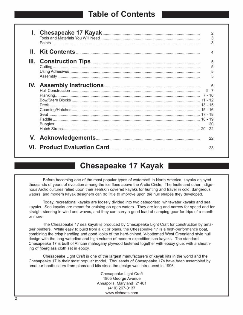
Table of Contents
Chesapeake 17 Kayak Before becoming one of the most popular types of watercraft in North America, kayaks enjoyed thousands of years of evolution among the ice floes above the Arctic Circle. The Inuits and other indige-nous Arctic cultures relied upon their sealskin covered kayaks for hunting and travel in cold, dangerous waters, and modern kayak designers can do little to improve upon the hull shapes they developed.
Today, recreational kayaks are loosely divided into two categories: whitewater kayaks and sea kayaks. Sea kayaks are meant for cruising on open waters. They are long and narrow for speed and for straight steering in wind and waves, and they can carry a good load of camping gear for trips of a month or more.
The Chesapeake 17 sea kayak is produced by Chesapeake Light Craft for construction by ama-teur builders. While easy to build from a kit or plans, the Chesapeake 17 is a high-performance boat, combining the crisp handling and good looks of the hard-chined, V-bottomed West Greenland style hull design with the long waterline and high volume of modern expedition sea kayaks. The standard Chesapeake 17 is built of African mahogany plywood fastened together with epoxy glue, with a sheath-ing of fiberglass cloth set in epoxy.
Chesapeake Light Craft is one of the largest manufacturers of kayak kits in the world and the Chesapeake 17 is their most popular model. Thousands of Chesapeake 17s have been assembled by amateur boatbuilders from plans and kits since the design was introduced in 1996.
Chesapeake Light Craft1805 George Avenue
Annapolis, Maryland 21401(410) 267-0137
www.clcboats.com2
I. Chesapeake 17 Kayak ........................................................................................ 2 Tools and Materials You Will Need .......................................................................................... 3 Paints ...................................................................................................................................... 3
II. Kit Contents ................................................................................................................ 4
III. Construction Tips .................................................................................................. 5 Cutting ..................................................................................................................................... 5 Using Adhesives ...................................................................................................................... 5 Assembly ................................................................................................................................. 5
IV. Assembly Instructions ....................................................................................... 6 Hull Construction ..................................................................................................................... 6 - 7 Planking ................................................................................................................................... 7 - 10 Bow/Stern Blocks .................................................................................................................... 11 - 12 Deck ........................................................................................................................................ 13 - 15 Coaming/Hatches .................................................................................................................... 15 - 16 Seat ......................................................................................................................................... 17 - 18 Paddle ..................................................................................................................................... 18 - 19 Bungies ................................................................................................................................... 20 Hatch Straps ............................................................................................................................ 20 - 22
V. Acknowledgements .............................................................................................. 22
VI. Product Evaluation Card ................................................................................. 23

Instant Setting (thin CA) Cyanoacrylate (super-glue type) adhesive - Used to instantly bond parts.
Slow Setting (medium CA) Cyanoacrylate (super-glue type) adhesive - Used to glue parts that are to be moved for alignment.
Note: Cyanoacrylate adhesives are manufac-tured in many different formulations, some of which do not work well on models. Consult your local hobby dealer for the proper adhesive brands.
Warning: Cyanoacrylate adhesives cure (dry) very rapidly. Read all warnings and safety pre-cautions on the label.
Accelerator - Used to speed up the drying time of the cyanoacrylate adhesives.
Water-based (white) Glue - Optional adhesive instead of cyanoacrylates.
Sanding Blocks - Glue pieces of sandpaper to one side of a block about 1/2” x 3” x 6” (13 x 76 x 152).
#120, #320 and #400 Grit Sandpaper - Used to sand and shape wood parts.
Tools and Materials You Will Need
6” and 18” (152 and 457) Steel Straight Edge - Used to measure parts and as a guide for cutting straight lines.
Hobby Knife and Extra Blades
Tack Rag
Paper Towel
Wax Paper
Pencil
Small Square
Jeweler’s Files
#0000 Steel Wool
Pin Vise - The pin vise is a small handle and chuck for holding a drill bit.
.025” Drill Bit
Nail Clippers
Masking Tape
Glue Stick
Paints
The following list of paints were used on the prototype seen on the box cover. However, in real life, kayaks tend to reflect their owner’s personal likes and skills, so it is quite appropriate to paint your model to suit your own taste. Your Hobby Dealer can recommend appropriate paints and explain their application.
Paints Used on the Prototype Chesapeake 17 Model
Testors Flat White (spray) stock #1258Testors Gloss White (spray) stock #1245Testors Glosscote (spray) stock #1261
Available from your Hardware Store:Early American Stain 8oz.
3

Kit Contents
Part No. Qty. Dimensions Metric Description34600 1 1/16” x 3/16” x 6-7/8” 1.5 x 4.7 x 175 Mahogany Paddle Blades30069 4 3/32” x 3/32” x 17-7/8” 2.3 x 2.3 x 454 Bass Chine / Sheer Clamps34598 2 1/4” x 1/4” x 17-7/8” 6.4 x 6.4 x 454 Bass Strongback Rails
Stripwood
Dowels34599 1 1/8” x 7-1/2” 3.2 x 191 Dowel Paddle Handle
34597 1 1/4” x 1/4” x 1-7/8” 6.4 x 6.4 x 47.6 Bass Paddle Jig34595 1 11/16” x 13/16” x 1-5/16” 18 x 21 x 33 Bass Bow Block34596 1 21/32” x 21/32” x 1-3/16” 17 x 17 x 30 Bass Stern Block
Pre-Shaped Parts
Fittings
Die-Cut Parts
Miscellaneous
M-813 1 1/8” x 24” Black Ribbon 3.2 x 610 Black Ribbon Hatch StrapsM-814 1 4’ Black Elastic Thread 1219 Black Elastic Thread Hold Down BungiesM-815 1 3” x 3” Black Felt 76 x 76 Black Felt Seat Cushion MaterialM-816 24 1/2” Pins 13 Pins Deck FastenersM-817 1 .016” Photo-Etched Brass .4 Photo-Etched Brass Set of 6 Buckles
P-610 1 12” x 24” 305 x 610 Plan (2 sheets)P-609 1 8-1/2” x 11” 216 x 279 24 page Manual
Laser-Cut Parts
Part #34590 - 1 RequiredLite Ply 3mm x 1-7/8” x 15-7/8”
(3 x 48 x 403)Part #34591 - 2 RequiredBass 1/32” x 3” x 17-7/8”
(.8 x 76 x 454)
Part #34592 - 1 RequiredPly 1/32” x 3-7/8” x 17-7/8”
(.8 x 98 x 454)
Part #34593 - 1 RequiredLite Ply 3mm x 2” x 7”
(3 x 51 x 178)
Part #34594 - 1 RequiredPly 1/32” x 4” x 6”(.8 x 102 x 152)
SPINE
SIDE PLANK
BOTTOM PLANK
DECKSEAT BOTTOM
FORWARD HATCHREAR HATCH
F-3
F-1
F-4
F-2COAMING SPACERS
COAMING
SEAT BACK
4

Construction Tips
When cutting parts with your knife, make the first cut with light pressure, being careful that the point of the knife goes exactly where you want it. Subsequent cuts should be made with moderate pres-sure until the part is cut out. Use a steel straight edge to guide the blade when cutting straight lines.
Cutting
Although water-based (white) glues can be used to build this kit, we found it advantageous to use cyanoacrylate (CA) adhesives, because they cure in seconds, so pins or tape are not necessary to hold thin or small parts in position.
When using instant setting (thin) cyanoacrylate adhesives, hold the parts to be joined in their exact positions and then run the adhesive into the joint. The parts will bond instantly.
When using slow setting (medium) cyanoacrylate adhesives, apply the adhesive to one of the parts and then join the assembly. Hold the part in position until the adhesive cures, about 30 seconds. Accelerator can be sprayed over the adhesive to cure it instantly.
The instructions will tell you which adhesive to use for each assembly.
Adhesives
In order to build this model correctly and easily, these instructions must be followed in the order that they are presented.
Check-off boxes () appear next to each instruction throughout the text to help you keep track of your progress. Dual check-off boxes () appear next to the instructions that are to be repeated.
Some of the sections in this manual do not have check-off boxes. These sections explain general procedures, rather than specific instructions.
The illustrations in this manual are not necessarily proportionally correct. Their purpose is to augment the written instructions, and also to clarify and detail many of the assemblies shown on the plan. This manual and the plan should be used together during construction.
Use the items listed on the previous pages to mark and identify all of the parts you will need to build this kit. Once you have made sure that all of the parts listed are in the box you can begin construction. If there are some missing parts, refer to the front of this manual for customer service.
Some of the parts on the die-cut and laser-cut sheets are held in place with notches. Before attempting to remove any die-cut or laser-cut parts, cut through these notches with a sharp hobby knife.
Assembly
5
IMPORTANTBefore beginning construction, tape the two plan
sheets together as indicated on the plans.
Hull Construction
1. Cover the building jig portion of the plan with wax paper.
2. Cross pin the two 1/4” x 1/4” x 17-7/8” (6.4 x 6.4 x 454) Basswood strongback rails in place.
3. Carefully remove frames F-1 through F-4 from the laser-cut sheet.
4. Use a sanding block with #120 grit sandpaper to lightly sand the edges of the parts, removing only the burrs and rough spots. Be sure to hold the sanding block at a 90 degree angle while sanding.
5. Place F-1 through F-4 on the strongback rails. Use a square to position them perpendicular to the strongback rails and glue in place with medium CA.
6. Position the spine in place by inserting F-1 through F-4 into the corresponding slots of the spine. Sight down the spine to be sure it is straight and comes into contact with F-1 through F-4.
Note: The spine is tabbed with the cockpit cutout. Do not remove at this time. If you accidentally crack the tabs, use masking tape on both sides to secure the cutout to the spine.
7. Make any necessary adjustments and glue each joint with medium CA.
8. Note: The hull is now inverted on the strongback. Any reference to the top and bottom refers to the hull as it floats upright on the water.
9. Using medium CA, glue a 3/32” x 3/32” x 17-7/8” (2.3 x 2.3 x 454) Basswood sheer clamp in the upper notch of F-1, as shown.
10. Working from F-1 towards F-4, glue the sheer clamp in the upper notch of each frame, as shown.
11. Repeat steps 9 - 10 for the opposite side.
WAX PAPER
F-1
F-4
F-2
F-3
SPINE
DO NOT REMOVE
SHEER CLAMP
SQUARE
6

12. Using medium CA, glue a 3/32” x 3/32” x 17-7/8” (2.3 x 2.3 x 454) Basswood chine clamp to the edge of F-1, as shown.
13. Working from F-1 towards F-4, glue the chine clamp in the lower notch of F-2 & F-3, and to the edge of F-4, as shown.
14. Repeat steps 12 - 13 for the opposite side.
15. Trim and sand the sheer/chine clamps flush with the outside edges of F-1 and F-4, as shown.
16. Remove the pins holding the strongback rails to the building board. Do not remove the hull from the strongback rails at this time!
17. It is necessary to “fair” the sheer/chine clamps so the bottom and side planks conform to the shape of each frame. An easy method of obtaining the correct shape is as follows:
18. At each frame, carefully sand the outside edge of the sheer clamp flush with the sides of each frame, as shown.
Note: Be careful not to sand too much and alter the shape of the frames.
19. Repeat the above process for the side and bottom of the chine clamp, as shown.
Tip: An easy way to check your progress is to use a 6” (152) straight edge. Place the edge of the straight edge against the side and bottom of each frame. The straight edge should lay flush with the side and bottom of each frame, as shown.
20. Using 120 grit sandpaper on a sanding block, fair the sheer/chine clamps along their complete length.
Note: Use the 6” (152) straight edge to verify your progress.
Planking
The die-cut bottom and side planks are slightly oversize to allow for optimal positioning. The excess will be trimmed and sanded to the final shape.
21. Re-pin the strongback rails to the building board.
22. Position the die-cut 1/32” (.8) Basswood bottom plank so that the inside edge is exactly on the centerline of the spine, with the plank overhang-ing F-1 through F-4 equally.
TRIM FLUSH
F-1
F-4
SHEER CLAMP
CHINE CLAMP
SAND AWAY SHADED AREA
F-3
CORRECTINCORRECT
STRAIGHT EDGE
SHEER CLAMP
CHINE CLAMP
SHEER CLAMP
CHINE CLAMP
OVERHANG FRAMES
ALIGN WITH CENTERLINE
OF SPINE
7

23.Carefully lift the bottom plank from the hull and place a bead of medium CA on the bottom of F-3, as shown. Replace the bottom plank as before and allow to dry completely.
24. Again, carefully lift the bottom plank from F-2 and apply a bead of medium CA on the bottom of F-2, as shown. Press the bottom plank against F-2 and allow to dry completely.
25. Lift each end of the bottom plank and place a drop of medium CA on the bottom of F-1 and F-4. Press the bottom plank against F-1 & F-4 and allow to dry completely.
26. Repeat steps 22 - 25 for the opposite side.
27. Remove the pins holding the strongback rails to the building board. Do not remove the hull from the strongback rails at this time!
28. Turn over the hull and using thin CA, glue the bot-tom plank to the spine, chine clamp and each frame from the inside of the hull.
GLUE TO F-3
GLUE TO F-2
GLUE TO F-1
GLUE TO F-4
GLUE TO SPINE AND FRAMES
FROM THE INSIDEBOTTOM PLANK
8
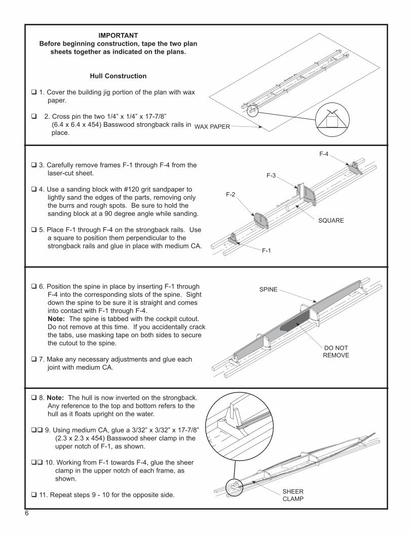
29. Use a hobby knife to carefully trim the bottom plank about 1/16” (1.5) from the outside edge of the chine clamp.
30. Sand the bottom plank flush with the outside edge of the chine clamp with #120 grit sanding block. Be sure to maintain the correct shape of the hull.
31. Re-pin the strongback rails to the building board.
32. Position the die-cut 1/32” (.8) Basswood side plank with an equal amount overhanging F-1 &
F-4. Note: The tall end of the plank goes toward F-1.
33. Place a bead of medium CA on the side of F-3, as shown. Press the side plank against F-3 and allow to dry completely.
34. Carefully lift the side plank away from the hull and place a bead of medium CA on the side of F-2, as shown. Press the side plank against F-2 and allow to dry completely.
SAND FLUSH WITH CHINE CLAMPS
TOP VIEW
SIDE PLANK
F-1
F-4
GLUE TO F-3
GLUE TO F-2
TALL END
9

35. Lift each end of the side plank away from the hull and place a bead of medium CA on the side of
F-1 & F-4. Press the side plank against F-1 & F-4 and allow to dry completely.
36. Repeat steps 32 - 35 for the opposite side.
37. Remove the pins holding the strongback rails to the building board.
38. Using a hobby knife, carefully cut through the tabs on the frames to remove the strongback rails and frame jigs from the hull, as shown.
39. Using medium CA, glue the side plank to the chine clamp and the sheer clamp from the inside. Trim and sand the bottom and side planks flush with the outside edges of F-1 and F-4, as shown.
40. Carefully trim and sand the side planks flush with the bottom plank and the top of the sheer clamp, as shown.
GLUE TO F-1
GLUE TO F-4
REMOVE STRONGBACK RAILS AND JIG FRAMES
TRIM FLUSH TO F-1
TRIM FLUSH TO F-4
TRIM FLUSH CHINE CLAMP
TRIM FLUSH SHEER CLAMP
10

Bow/Stern Blocks
41. Carefully mark the exact center around the bow and stern blocks, as shown, Using a straight edge, draw a centerline on the top, bottom and front surfaces of the blocks, as shown.
Note: These centerlines act as reference lines and it is important that they are correct.
42. Using medium CA, glue the bow block to F-1. Be sure that the bottom centerline on the bow block is positioned in-line with the seam of the bottom planks. Also, the top centerline on the bow block is positioned in the middle of F-1.
43. Carefully cut the bow block template from the plan along the dotted lines.
44. Using a glue stick, glue the bow block template to the top of the bow block. Be sure to keep the centerlines in-line, as shown.
45. Using a hobby knife, carefully shave off small slices of the excess bow block. Trim the bow block to the template lines, as shown.
CENTERLINES
CENTERLINE
SEAM OF BOTTOM PLANKS
BOW BLOCK TEMPLATE
REMOVE SHADED AREA
TRIM TO HERE
11

46. Now, trim both sides of the bow block to conform to the side planks. Only trim the sides to the cen-terline on the front of the bow block, as shown. Be careful not to trim through the centerline on the front of the bow block, changing the profile shape.
47. Using #120 grit sanding block, sand the bow block sides to final shape. Be careful not to sand through the centerline on the front of the bow block, changing the profile shape.
48. Sand the bottom of the bow block to conform to the bottom planks, as shown.
49. Using a hobby knife, peel off the bow block template. Sand the top of the bow block to con-
form with the top of F-1 and the sheer clamps, as shown.
Note: The top of the bow block should maintain the camber of the deck.
50. Repeat steps 42 - 49 for the stern block.
51. Using a hobby knife, carefully cut the two tabs at the top of the spine holding the cockpit cutout. Carefully bend the cockpit cutout over and remove it from the hull.
52. Sand the cockpit cutout area smooth.
REMOVE SHADED AREA
SHAPE TO CONFORM TO BOTTOM PLANKS
TRIM TO CONFORM TO SIDE PLANKS
REMOVE SHADED AREA
SHAPE TO CONFORM TO F-1
REMOVE SHADED AREA
CUT TABS HERE
F-1
FRONT VIEW
CENTERLINE
FRONT VIEW
CENTERLINE
12

Deck 53. Prime the outside of the hull and between F-2 and
F-3 inside the hull. Note: The primer will seal the grain of the wood,
allowing for a smooth finish. In addition, the prim-er will show any areas that need more sanding.
54. Sand the primed areas with #320 grit sandpaper.
55. Continue priming and sanding between coats until you are satisfied with the appearance.
56. While the hull is being primed, stain the complete top and cockpit area inside the die-cut 1/32” (.8)
plywood deck.
57. When satisfied with the cockpit area inside the hull, mask the hull, as shown.
58. Paint the cockpit flat white. Allow to dry completely. Remove the masking tape.
59. Place the stained deck upside down on the building board.
60. Place a bead of medium CA on the top of the spine from the front edge of the cockpit cutout to the bow block, as shown.
61. Turn the hull upside down and center it on the deck, as shown. Be sure the front of the deck is facing the front of the hull! Allow to dry
completely. Note: Do not glue along the edges of the deck at
this time!
PRIME SHADED AREA
MASK HULL
WITH PAPER
PAINT COCKPIT AREA
BEAD OF MEDIUM CA
DECK
STAIN ENTIRE SHADED AREA
STAIN UNDERSIDE OF DARKER AREA
13

62. Place a bead of medium CA on the top of the spine from F-3 to the stern block. Press the deck against the spine and allow to dry completely.
63. Place a bead of medium CA on top of F-1, F-2 and the front 6” of the sheer clamp, as shown. Turn the hull upside down on the building board and press the deck against the sheer clamp, as shown. Allow to dry completely.
64. Apply a bead of medium CA on top of the sheer clamp from 6” (152) back to F-3, as shown. Turn the hull upside down on the building board and press the deck against the sheer clamp, as shown. Allow to dry completely.
65. Apply a bead of medium CA on top of the sheer clamp, F-3 & F-4, as shown. Turn the hull upside down on the building board and press the deck against the sheer clamp, as shown. Allow to dry completely.
66. Repeat steps 63 - 65 for the opposite side.
BEAD OF MEDIUM CA
F-3
GLUE HERE
PRESS AGAINST
SHEER CLAMP
GLUE HERE
PRESS AGAINST
SHEER CLAMP
GLUE HERE
PRESS AGAINST
SHEER CLAMP
14

67. Carefully trim and sand the deck flush with the side planks, as shown.
68. Mask off the inside of the cockpit and deck sides with masking tape, as shown.
69. Seal the deck with three coats of Testor's Gloss Clear Coat. Sand between each coat with #0000 steel wool.
70. Remove the masking tape from the hull.
71. Mask off the top of the deck with masking tape. Leave about 1/8” (3.2) of deck around the edge, as shown.
72. Spray a light coat of Testor’s gloss clear coat around the edge of the masking tape.
Note: The clear coat seals the edge of the masking tape to the deck. If any paint “leaks”
under the masking tape, it will be clear paint on clear paint. Allow to dry completely.
73. Spray paint the hull. Allow to dry completely.
74. Remove the masking tape from the deck.
Coaming
75. Using a sharp hobby knife, carefully cut through the tabs and remove the coaming and the two coaming spacers from the laser-cut 1/32” (.8)
plywood.
76. Using medium CA, glue the two coaming spacers together, as shown.
MASK WITH PAPER
MASK WITH PAPER
SPRAY POLY-URETHANE
MASK WITH TAPE
COAMING SPACERS
TRIM FLUSH
15

77. Carefully sand the inside and outside edges of the coaming and coaming spacer with #120 grit sand-paper. This is to remove the charring left from the laser-cutting operation.
78. Remove the front and rear hatches from the die-cut 1/32” (.8) plywood.
79. Apply a coat of stain to the top of both hatches, the coaming and the edges of the coaming spacer. Allow the stain to dry completely.
80. Using medium CA, glue the coaming to the coaming spacer, as shown.
81. Seal the hatches and coaming with three coats of Testor's Gloss Clear Coat. Sand between coats with #0000 steel wool.
82. Using medium CA, glue the hatches and coaming to the deck at the locations shown on the plan.
83. Mask off the inside of the cockpit with masking tape, as shown.
84. Apply two coats of Testor’s gloss clear coat to the complete kayak.
STAIN
STAIN
COAMING SPACERS
COAMING
REAR HATCH
FORWARD HATCH
COAMING
MASK
16

Seat
85. Remove the seat bottom from the die-cut 1/32” (.8) plywood.
86. Cut the 3” x 3” (76 x 76) felt in two pieces, 1-1/2” x 3” (51 x 76).
87. Remove the protective backing paper from one of the felt pieces. Place the seat bottom in the
center of the felt, as shown.
88. Carefully trim the felt about 1/16” (1.5) around the seat bottom, as shown.
89. Fold the 1/16” (1.5) overhang around the edges of the seat bottom.
90. Remove the seat back from the die-cut 1/32” (.8) Basswood.
91. Dampen the seat back with warm water and tape around a film canister or glue bottle to shape it, as shown.
92. Using a pin, make several pricks through the tape and into the wood. This allows the water to
evaporate. Allow to dry for a couple of hours.
93. Carefully remove the tape.
94. Using thin CA, saturate the seat back to maintain the curve.
SEAT BOTTOM
FELTCUT AROUND SEAT BOTTOM 1/16”
1-1/2”
3”
SEAT BACK
TAPE
CANISTER
PIN HOLES
THIN CA
SEAT BACK
TOP VIEW OF SEAT BACK
17

95. Remove the protective backing paper from the remaining felt piece. Apply the felt to the inside of the seat back, as shown.
96. Carefully trim the felt about 1/16” (1.5) around the seat back. Fold the 1/16” (1.5) overhang around the edges of the seat back.
97. Using medium CA, glue the seat bottom and back inside the cockpit, as shown on the plan.
Paddle
98. Cut four paddle blades, each 1-1/2” (38) long, from the 1/16” x 3/16” x 6-7/8” (1.5 x 4.7 x 175) Mahogany.
99. Using medium CA, glue two paddle blades to one end of the 1/8” x 7-1/2” (3.2 x 191) Dowel paddle handle, as shown. Be sure to align the paddle blades parallel to each other.
FELT THE CON-CAVE SIDE OF
THE SEAT BACK
SEAT BACK
SEAT BOTTOM
1-1/2”
DOWEL PADDLE HANDLE
PADDLE BLADES
18

100. Position the completed end of the paddle against the angle on the paddle jig, as shown.
101. Mark a horizontal line across the other end of the Dowel with a pencil, as shown.
102. Using medium CA, glue the remaining two paddle blades to the end of the Dowel, in line
with the pencil mark, as shown.
103. Carefully cut the paddle blade templates from the plan along the dotted lines.
104. Using a glue stick, attach one template to each end of the paddle.
105. Carefully trim and sand the paddle ends to the template lines, as shown. Remove the tem-plates and round the edges of the paddle blades, as shown.
106. Seal the completed paddle with two coats of Testor's Gloss Clear Coat.
HORIZONTAL LINE
PADDLE BLADES IN LINE WITH HORIZONTAL
LINE
PADDLE BLADE TEMPLATES
19
ROUND EDGES
END VIEW END VIEW
BEFORE AFTER

Bungies 107. Using the plan, mark the positions of the four bungie
fasteners behind the cockpit, as shown.
108. Using a .025” drill bit and pin vise, drill a hole at each fastener location.
Note: All deck fastener holes should be drilled through the deck and the sheer clamp. To prevent the holes from exiting the hull side, be sure to drill the holes at a slight angle into the center of the hull, as shown.
109. Insert a 1/2” (13) pin about half way into each hole, as shown.
110. Cut an 18” (457) piece from the 4’ (1220) of black elastic thread.
111. Use the diagram to tie the bungie cord around the pins. Tie the elastic thread off with a double knot and trim the excess with nail clippers.
Note: Do not stretch the thread completely when tying the knot.
112. Using the plan, mark the six holes for the forward deck bungie. Using the remaining piece of elastic thread, repeat the above process for the forward deck bungie.
113. Push the pins completely down.
Hatch Straps
114. Using the plan, mark the positions of the six rear hatch strap fasteners, as shown.
115. Using a .025” drill bit, drill a hole at each fastener location.
.025” DRILL BIT
INSERT PINS HALFWAY INTO
THE HOLES
START
TIE OFF
STARTTIE OFF
.025” HOLES
.025” HOLES
20
DRILL HOLES AT A SLIGHT ANGLE
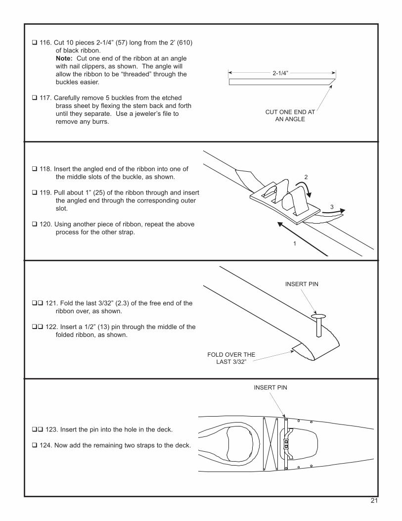
116. Cut 10 pieces 2-1/4” (57) long from the 2’ (610) of black ribbon.
Note: Cut one end of the ribbon at an angle with nail clippers, as shown. The angle will allow the ribbon to be “threaded” through the buckles easier.
117. Carefully remove 5 buckles from the etched brass sheet by flexing the stem back and forth until they separate. Use a jeweler’s file to remove any burrs.
118. Insert the angled end of the ribbon into one of the middle slots of the buckle, as shown.
119. Pull about 1” (25) of the ribbon through and insert the angled end through the corresponding outer slot.
120. Using another piece of ribbon, repeat the above process for the other strap.
121. Fold the last 3/32” (2.3) of the free end of the ribbon over, as shown.
122. Insert a 1/2” (13) pin through the middle of the folded ribbon, as shown.
123. Insert the pin into the hole in the deck.
124. Now add the remaining two straps to the deck.
2-1/4”
CUT ONE END AT AN ANGLE
FOLD OVER THE LAST 3/32”
INSERT PIN
INSERT PIN
21
1
2
3

125. Carefully pull the excess strap material through the buckle until the buckle is centered over the hatch. Using nail clippers, trim the excess strap material about an 1/8” (3.2) from the buckle, as shown.
126. Repeat the above process for the remaining four hatch straps/buckles.
TRIM STRAPS 1/8” FROM BUCKLE
Acknowledgements
The following people contributed to the development of this kit and to the production of this construction manual.
Model Designed & Engineered by: A.J. Broviak
Manual Written by: A.J. Broviak
Manual Illustrated & Assembled by: Andy Biggs
Special Thanks to Chesapeake Light Craft.
22
Wood canvas construction was pioneered in Maine; it first appeared commercially in the mid 1870’s, becoming the standard for canoes, cheaper than all wood construction.
I t was in the area around
Peterboro, Ontario that the car-
pentered canoe built with European woodworking skills
was first “perfected”, about the mid 1800’s.
Indian Girl Canoe Kit #981 Peterboro Canoe Kit #982
Length: 15-7/8”Beam: 2-3/4”Height: 2”Scale: 1” = 1’Strip Plank ConstructionSkill Level 2
Length: 15-7/8”Beam: 2-5/8”Height: 1-1/2”Scale: 1” = 1’Strip Plank ConstructionSkill Level 2
Look for These Other Great Success Series Apprentice Kits

Product Evaluation Card
What you tell us you like, and don’t like, determines what model kits we make and how we make them. We would appreciate it if you would take a few minutes to answer the following questions about this kit, and also tell us a little about your interests. When finished, simply fold this form in thirds and tape it (PLEASE DO NOT STAPLE) so that our address faces out, and return this form to Midwest. Thank you for your time.
1. Kit Name Chesapeake 17 Kayak 2. Kit Number 989 3. Where did you learn about this kit? o Magazine Ads o Friend o Hobby Shop o Other
4. What influenced you the most to buy this kit? o Box Art o Recommendation of Others o Type of Model o Price o Magazine Ads o Other ________________
5. Did you have any trouble using the plans? o Yes o No If yes, please explain. Be specific.
________________________________________________ ________________________________________________
6. Did you have any difficulty understanding any of the written instructions on the plans, or in the construction manual? o Yes o No If yes, please explain. Be specific.
________________________________________________ ________________________________________________
7. Did you have any difficulty understanding any of the illustrations in the construction manual? o Yes o No If yes, please explain. Be specific.
________________________________________________ ________________________________________________
8. Did you have any difficulty identifying any of the parts? o Yes o No If yes, which parts?
________________________________________________ ________________________________________________
9. If you answered yes to Question 8, which of the following answers best describes the problem? Could not identify part(s) from: o Plans o Written description in manual o Isometric views in manual o Other ________________
10. Were any of the kit parts: o Missing o Wrong Size o Broken o Wrong Shape
11. If you checked off an item in Question 10, please list those part(s) and tell us what was wrong with them.
________________________________________________ ________________________________________________
12. Was any of the model's construction difficult for you? o Yes o No If yes, please explain.
________________________________________________ ________________________________________________ ________________________________________________
13. What did you like most about this kit? o Plans o Wood Parts o Construction Manual
14. What did you like least about this kit? o Plans o Wood Parts o Construction Manual o Other If other, please explain. Be specific.
________________________________________________ ________________________________________________
15. Are you satisfied with the finished model? o Yes o No If no, please explain. Be specific.
________________________________________________ ________________________________________________
16. How does this kit compare to similar kits by other manufacturers? o Better than o As good o Not as good
17. Is there anything else you would like to tell us about this kit?
________________________________________________ ________________________________________________ ________________________________________________ ________________________________________________ ________________________________________________ ________________________________________________
Tell Us About Yourself
18. How long have you been building models? ________________________________________________
19. What magazines do you regularly read? ________________________________________________
20. Are most of your models built from: o Plans o Kits o Scratch built using your own plans
21. What other subjects would you like to see us add to our Success Series Boat kits line
________________________________________________ ________________________________________________ ________________________________________________ ________________________________________________
22. Kit was purchased from: o Hobby Shop o Mail Order o Other ____________________
Name ______________________________________ Age ________________
E-Mail Address ___________________________________________________
Address _________________________________________________________
City _______________________________________________
State ______________________________________ Zip _________________
Phone (Area Code) ________________________________________________
23

CUSTOMER CARE DEPARTMENTPO BOX 564HOBART IN 46342-9966
PlaceStampHere
Fold along dashed lines so the address faces out