Embed Size (px)
Citation preview

Chemical Engineering Journal 219 (2013) 419–428
Contents lists available at SciVerse ScienceDirect
Chemical Engineering Journal
journal homepage: www.elsevier .com/locate /cej
Recycling of high temperature steam condensed water from petroleumrefinery by thermostable PPESK ultrafiltration membrane
1385-8947/$ - see front matter � 2013 Elsevier B.V. All rights reserved.http://dx.doi.org/10.1016/j.cej.2012.12.101
⇑ Corresponding author. Address: School of Municipal and Environmental Engi-neering, Harbin Institute of Technology, No. 73 Huanghe Road, Nangang District,Harbin 150090, China. Tel./fax: +86 451 86283801.
E-mail address: [email protected] (P. Wang).
Shanshan Zhao a, Peng Wang a,⇑, Ce Wang a, James L. Langer b, Gulizhaer Abulikemu a, Xin Sun a
a State Key Laboratory of Urban Water Resource and Environment, School of Municipal and Environmental Engineering, Harbin Institute of Technology, Harbin 150090, PR Chinab Serionix, Inc., 60 Hazelwood Dr., Champaign, IL 61820, United States
h i g h l i g h t s
" Excess oil and iron in high temperature condensed water are removed by UF membrane." Operation parameters affect permeate flux, removal efficiencies and membrane fouling." Membrane performance is recovered after NaOH in combination with ethanol washing." Reclaiming high temperature condensed water can prevent thermal emission pollution." Reclaiming it also reduces economic cost, saves energy and realizes water recycling.
a r t i c l e i n f o
Article history:Received 21 August 2012Received in revised form 28 December 2012Accepted 29 December 2012Available online 11 January 2013
Keywords:High temperature condensed waterUltrafiltrationThermostable PPESK membraneReclaiming and utilization
a b s t r a c t
The purification and reclaiming of synthetic and industrial high temperature condensed water containingexcess oil and iron is investigated in this study using thermostable poly(phthalazine ether sulfoneketone) (PPESK) ultrafiltration membranes. The results show operation parameters such as transmem-brane pressure, temperature and pH of feed solution, initial oil and iron concentration each play impor-tant roles in the permeate flux and oil/iron removal efficiencies. Membrane performance is almostrecovered after washing with a combination of NaOH and ethanol. High temperature condensed waterfrom Daqing petroleum refinery can be consecutively purified using a PPESK ultrafiltration membrane.The turbidity of the solutions is almost removed. Oil and iron concentrations in the permeate solutionsare below 1 mg/L and 50 lg/L, respectively, which satisfy the Quality Criterion of Water and Steam forSteam Power Equipment in China. UF process shows a promising alternative to existing technology inthe Daqing petroleum refinery in terms of cost and environmental protection as well as energy recovery.For future possible combination of UF and NF process application, both economic cost and saving areevaluated, and the breakeven time is about 11 months.
� 2013 Elsevier B.V. All rights reserved.
1. Introduction
High temperature condensed water is produced from condensa-tion of high pressure steam during the heat exchange process [1],and contains up to 20–30% of the heat quantity of the steam [2].If the condensed water is discharged directly, heat energy is lost,large amounts of water are wasted, and sewage discharge feesare assessed, resulting in unnecessary expenses [3,4]. Moreover, di-rect discharge of condensed water into an aquatic environmentcauses thermal emission pollution—an increase in water tempera-ture, which negatively influences both water quality and growth
and distribution of aquatic organisms [5–8]. Reclaiming and utiliz-ing high temperature condensed water is of great significance forconserving water and energy and for preventing thermal emissionpollution.
Condensed water is typically used as boiler makeup water or,after treatment, hot water for residential use in winter. However,high temperature condensed water produced in petroleum refiner-ies often contains excess oil and iron contaminants due to the leak-age and corrosion of equipments [9]. This contaminated condensedwater will damage or even destroy boilers if it is not properly puri-fied before reuse. The two principle modes of damage are: (1)adherence of oil to boiler tubes resulting in overheating of the fur-nace due to reduced heat transfer [10,11]; (2) partial corrosion ofboiler tubes resulting from iron contamination and leading to per-foration of boiler tubes due to the deposition of iron scale on themetal surface [12].
420 S. Zhao et al. / Chemical Engineering Journal 219 (2013) 419–428
Several technologies have been employed or explored to re-move oil and iron, including activated carbon adsorption, mixed-bed ion exchange, powder resin filtration, functional fiber filtrationand electrodeionization [9,13,14]. However, these conventionalmethods suffer from several problems, including operational insta-bility, higher cost and potential secondary waste pollution fromthe replacement of adsorbent or other filter materials.
In contrast, membrane technologies are a promising alternativeas they have the advantages of simple operation, small physicalfootprint, high separation efficiency, and low energy consumption[15,16]. Recently, a number of membrane separation processes,such as ultrafiltration (UF), nanofiltration (NF) and reverse osmosis(RO) have been applied efficiently for oil/water separation [17–19].Yi et al. [20] introduced response surface methodology (RSM) tooptimize operational parameters to mitigate membrane foulingduring ultrafiltration of oil/water emulsions. Chakrabarty et al.[21,22] successfully applied several kinds of polysulfone mem-branes with different additives for treating oily wastewater frompetroleum industries. Nearly all the membranes gave an oil rejec-tion of over 90%, and the oil concentration in the permeate solutionmet discharge requirements. Although membrane technologieshave been successfully applied for oily wastewater treatment,application in a high temperature condensed water purificationprocess has only been reported—for example boiler feedwatertreatment from GE Water & Process Technology. An UF systemhas been used for the removal of dissolved iron from boiler feed-water in a nuclear power plant in Colorado. Higher iron removalefficiency in this system has resulted in shortening the startingperiod of the nuclear power plant from a few days to just 8 h[23]. A RO system has also been successfully applied for reclama-tion of softened makeup water in an oil refinery in the MidwesternUnited States. Using these processes, it is estimated that over250 billion BTUs of energy can be saved per year because of thelower blowdown rates [24].
This paper focuses on the purification and recycling of the hightemperature steam condensed water from petroleum refineryusing thermostable UF membranes prepared using a phase-inver-sion method. The membrane material poly(phthalazine ether sul-fone ketone) (PPESK) contains rigid phthalazine structure andaromatic rings, showing extraordinary mechanical strength, ther-mal stability, and good chemical resistance [25]. Permeate fluxand oil and iron removal efficiencies were measured as a functionof changes in transmembrane pressure (TMP), temperature and pHvalue of feed solution, and initial oil and iron concentration. Vari-ous membrane cleaning methodologies were also considered.Lastly, purification efficiency and recycling of high temperaturesteam condensed water was studied using real samples acquiredfrom the Daqing petroleum refinery. The economic feasibilitywas also evaluated.
2. Materials and methods
2.1. Materials
Commercial PPESK powder (S:K = 1:1, Mw = 58000 g/mol) waspurchased from Dalian Polymer New Materials Co. Ltd. (Liaoning,China). Diesel oil was provided by a local gas station. N-methyl-2-pyrrolidone (NMP) was purchased from Beijing Yili Fine Chemi-cal Co., Ltd. (China). Polyethylene glycol (PEG, 4000 g/mol) was ob-tained from Aladdin Reagent (Shanghai, China). Sodium dodecylsulfate (SDS) was chemically pure grade and provided by TianjingGuangfu Fine Chemical Research Institute (Tianjin, China). FeSO4-
�7H2O and ferron agent (8-hydroxy-7-iodo-5-quinoline sulfonicacid) were purchased from Tianjing Bodi Chemical Co., Ltd. (China)and Beijing Hengye Zhongyuan Chemical Co., Ltd. (China). All
reagents were analytical grade, except for SDS, and used withoutfurther purification. Deionized (DI) water from a Milli-Q system(Millipore, Bedford, USA) was used in all experiments.
2.2. Membrane preparation
The PPESK membranes were prepared using a phase inversionmethod, the details of which can be found elsewhere [26]. The flowdiagram of membrane preparation process is shown in Fig. S1 inSupplementary materials file. First, 6 wt.% PEG was dissolved inNMP with stirring at 60 �C. Next, 16 wt.% PPESK power was addedto the solution with continuous vigorous stirring at 60 �C for 6 huntil it was completely dissolved. Afterwards, the solution was fil-tered to remove a small amount of insoluble impurity. Finally, auniform and homogeneous solution was obtained and kept at25 �C for 48 h to remove gas bubbles. Membranes were cast fromthe resulting solution using a glass plate with a 200-lm castingknife. After exposure to ambient air (temperature was 20 ± 2 �Cand relative humidity was 30 ± 5%) for 10 s, the glass plate was im-mersed into a DI water coagulation bath maintained at 20 ± 1 �C.Membranes thus obtained were stored in DI water for 1–2 daysto remove residual solvent, and then stored in 1% formaldehydesolution to avoid microbe growth. The molecular weight cut-off(MWCO) of the PPESK membrane is about 60,000 Da, which wasdetermined in our previous work [27]. Pore size distribution ofPPESK membrane was investigated using bubble point methodby using a Capillary Flow Porometer (Porolux 1000, IB-FT GmbH,Germany) [28] and the profile is shown in Fig. S2. The PPESK mem-brane exhibits a narrow pore size distribution, the bubble pointpore size is 65 nm and the mean pore size is 36 nm.
2.3. Simulated high temperature condensed water preparation
A certain amount of diesel oil, SDS and FeSO4�7H2O (the massratio of diesel oil to SDS was 3:1) were added into 3 L DI waterto give different oil and iron concentration solutions. SDS, as onecommon emulsifier, decreased the oil–water interface tensionand coated the dispersed oil droplets, protecting them from coales-cence and enhancing the emulsion solution stability. The solutionswere mixed using high-shear emulsifying dispersion for 30 min(the mixing speed was 3000 rpm). After that, the solutions weresealed with preservative film and heated to 80 �C in a water bath.During each ultrafiltration test, the high temperature condensedwater was kept at 80 �C using a water bath. Oil droplet size wasin the range of 0.45–1.01 lm with a volume average particle diam-eter of 0.73 lm, as measured by a Malvern Mastersizer Particle sizeanalyzer. Oil concentration was measured using an ultravioletspectrophotometer at 224 nm (UV2550, Shimadzu, Japan) afterextraction by hexane. Iron concentration was measured usingInductively Coupled Plasma-Atomic Emission Spectra (ICP-AES)(Optima 5300 DV, PerkinElmer, USA). The pH and turbidity wererecorded using a pH meter (Corning pH/ion analyzer 455, ColeP-armer, USA) and turbidity meter (Turb 550, WTW, Germany),respectively.
2.4. Ultrafiltration performance
The purification efficiency of high temperature condensedwater was characterized using a cross-flow filtration cell (providedby Tianjin Polytechnic University, China) connected with a solutionreservoir and an electric diaphragm pump. A schematic diagram ofthe experimental ultrafiltration set up is shown in Fig. 1. Effectivemembrane area was 17.71 cm2 and cross-flow velocity was kept at1.61 m/s. In order to keep the temperature of condensed water vir-tually constant, the entire experimental set up-including the test-ing cell and all pipes – were wrapped up using cotton for

1
2
3 4
5
6
7
Fig. 1. Schematic diagram of experimental set up of ultrafiltration (1. Water bath;2. feed solution; 3. electric diaphragm pump; 4. diaphragm pressure gauge; 5.testing cell; 6. valve; 7. measuring cylinder).
S. Zhao et al. / Chemical Engineering Journal 219 (2013) 419–428 421
insulation. Since the initial pure water flux of each membrane var-ied slightly, membranes exhibiting similar initial flux were se-lected for each group experiment. Each membrane was firstlypre-compacted with 80 �C pure water at 0.2 MPa for 30 min toachieve steady-state permeate flow. Then, pure water flux wasmeasured using 80 �C DI water at 0.1 MPa. Pure water flux of mem-branes ranged from 940 to 1050 L m�2 h�1. High temperature con-densed water was filtered at a constant TMP of 0.1 MPa aftermembrane pre-compaction. Both permeate and retentate solutionswere refilled into the feed solution to keep the concentration con-stant. The permeate flux (J, L m�2 h�1) was measured every minuteuntil it leveled off after 30 min, which can be calculated using thefollowing equation:
J ¼ VA� t
ð1Þ
where V is permeate volume (L), A is membrane area (m2), and t issample collection time (30 s).
The permeate samples were collected for measurement of theoil and iron concentrations and turbidity. The observed rejectioncan be calculated using the following equation:
R ¼ CF � CP
CF� 100% ð2Þ
where CF and CP are the concentrations in feed and permeate solu-tions (mg/L), respectively.
The normalized flux (J/J0) was applied to evaluate the mem-brane performance, where J0 is the initial permeate flux (L/m2 h).The flux decline rate (FD) was introduced to investigate the effectsof several factors on the membrane fouling, which was determinedusing the following equation:
FD ¼ 1� JP
J0
� �� 100% ð3Þ
where JP is the permeate flux after 30 min filtration (L/m2 h). Eachexperiment was repeated three times and the average value wasreported.
2.5. Membrane cleaning methods
To investigate the effects of different cleaning methods, thepure water flux recovery rate (FR) was introduced,FR ¼ ðJ0w=JwÞ � 100%, where Jw and J0w are the pure water flux of vir-gin membrane and cleaned membrane (L/m2 h), respectively. Eachmembrane was filtered with high temperature condensed waterfor 60 min and FD was around 50%.
The cleaning procedures are shown as below:
Method A: after an UF experiment, the membrane was washedby 80 �C DI water for 5 min at 0.05 MPa.Method B: after an UF experiment, the test cell was washed byDI water in room temperature for 5 min at 0.05 MPa to removeresidual contaminants in the cell and pipe and to cool down thecell. Then, the membrane was removed and gently cleaned by asponge ball to remove any contaminants loosely bonded to themembrane surface. Finally, the membrane was washed thor-oughly using DI water in room temperature.Method C: after an UF experiment, the membrane was washedusing 0.1 M NaOH solution for 5 min followed by DI waterwashing for 5 min to remove residual detergent.Method D: after an UF experiment, the membrane was washedusing 50% ethanol solution for 5 min followed by DI waterwashing for 5 min.Method E: after an UF experiment, the membrane was firstwashed using 0.1 M oxalic acid solution for 5 min followed byDI water washing for 5 min, and then the membrane waswashed using 50% ethanol solution for 5 min followed by DIwater washing for 5 min to remove residual detergent.Method F: the cleaning procedure was similar to method E, butthe detergents were changed for 0.01 M NaOH solution and0.1 M oxalic acid solution, respectively.Method G: the cleaning procedure was similar to method E, butthe detergents were changed for 0.01 M NaOH solution and0.1 M HCl solution, respectively.Method H: the cleaning procedure was similar to method E, butthe detergents were changed for 0.01 M NaOH solution and 30%ethanol solution, respectively.
All of the detergents and DI water used in methods C–H werecirculated in the testing cell at 0.05 MPa in room temperature.
2.6. Membrane surface morphology observation
The morphology of membrane surfaces was characterized usinga scanning electron microscope (SEM) (S4800, Hitachi). All mem-brane specimens were dried at room temperature for at least48 h and stored in a desiccator. The dry membranes were sputteredwith a thin layer of gold under vacuum for 20 s (Emitech K575Sputter Coater, Emitech Ltd., Ashford Kent, UK) prior to imaging.
3. Results and discussion
3.1. Membrane surface morphology
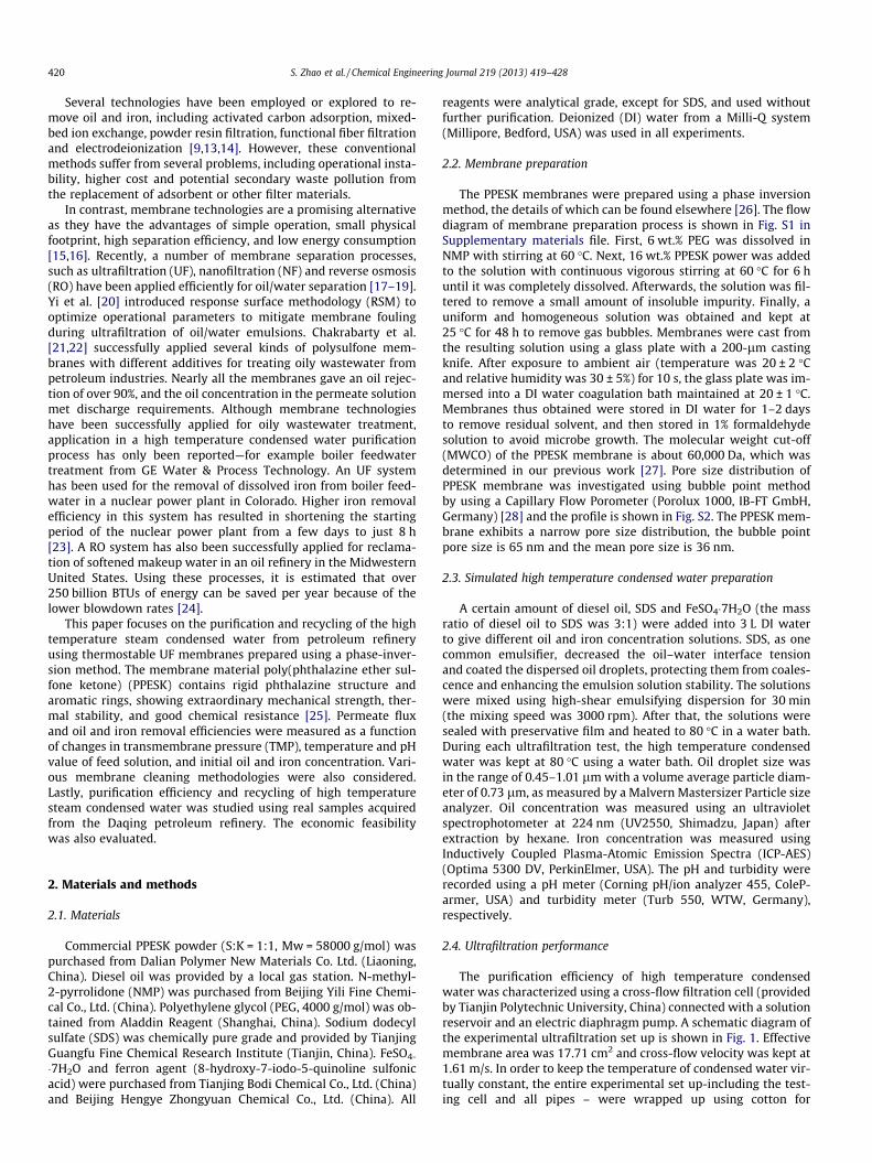
The SEM images of surface morphology of virgin and fouledPPESK membranes are illustrated in Fig. 2. Membrane pores canbe seen clearly on the virgin PPESK membrane surface, while an or-dered and compacted cake layer is formed on the fouled mem-brane surface, due to the accumulation and deposition of oilemulsion and iron hydrolysates.
3.2. The influences of important factors on the membrane performancefor high temperature condensed water purification
3.2.1. Effects of transmembrane pressureVariations in permeate flux and rejection of membranes during
high temperature condensed water purification at different TMPare shown in Fig. 3. Fig. 3a shows that the normalized flux de-creases with increasing time and finally levels off for each TMP,while the FD values increase proportionally with increasing pres-sure. The lower the pressure, the faster the permeate flux equili-brates. For example, when the pressure is 0.05 MPa, thepermeate flux is stable after 10 min filtration, while for the
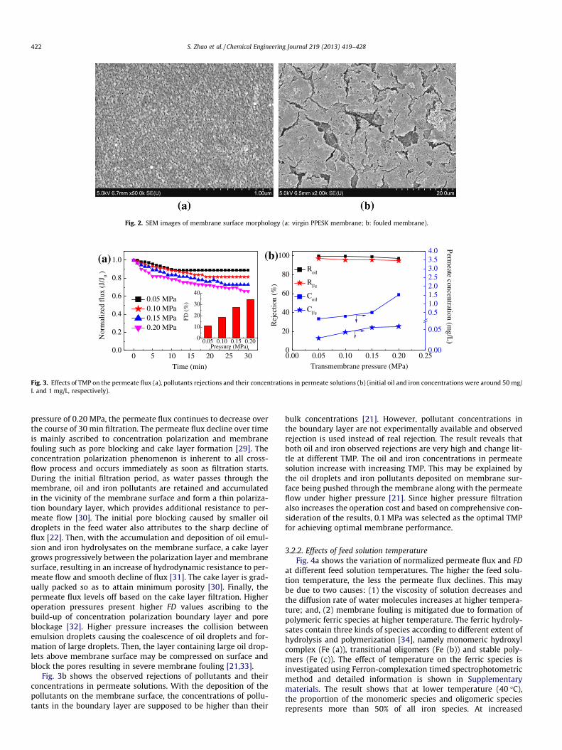
Fig. 2. SEM images of membrane surface morphology (a: virgin PPESK membrane; b: fouled membrane).
0 5 10 15 20 25 300.0
0.2
0.4
0.6
0.8
1.0
0.05 MPa 0.10 MPa 0.15 MPa 0.20 MPa
Nor
mal
ized
flu
x(J
/J ) 0
Time (min)
0.05 0.10 0.15 0.200
10
20
30
40
FD (
%)
Pressure (MPa)
0.00 0.05 0.10 0.15 0.20 0.250
20
40
60
80
100
Transmembrane pressure (MPa)
Rej
ectio
n (%
)
0.00
0.05
0.51.01.52.02.53.03.54.0(b)
Roil
RFe
Coil
CFe
Permeate concentration (m
g/L)
(a)
Fig. 3. Effects of TMP on the permeate flux (a), pollutants rejections and their concentrations in permeate solutions (b) (initial oil and iron concentrations were around 50 mg/L and 1 mg/L, respectively).
422 S. Zhao et al. / Chemical Engineering Journal 219 (2013) 419–428
pressure of 0.20 MPa, the permeate flux continues to decrease overthe course of 30 min filtration. The permeate flux decline over timeis mainly ascribed to concentration polarization and membranefouling such as pore blocking and cake layer formation [29]. Theconcentration polarization phenomenon is inherent to all cross-flow process and occurs immediately as soon as filtration starts.During the initial filtration period, as water passes through themembrane, oil and iron pollutants are retained and accumulatedin the vicinity of the membrane surface and form a thin polariza-tion boundary layer, which provides additional resistance to per-meate flow [30]. The initial pore blocking caused by smaller oildroplets in the feed water also attributes to the sharp decline offlux [22]. Then, with the accumulation and deposition of oil emul-sion and iron hydrolysates on the membrane surface, a cake layergrows progressively between the polarization layer and membranesurface, resulting in an increase of hydrodynamic resistance to per-meate flow and smooth decline of flux [31]. The cake layer is grad-ually packed so as to attain minimum porosity [30]. Finally, thepermeate flux levels off based on the cake layer filtration. Higheroperation pressures present higher FD values ascribing to thebuild-up of concentration polarization boundary layer and poreblockage [32]. Higher pressure increases the collision betweenemulsion droplets causing the coalescence of oil droplets and for-mation of large droplets. Then, the layer containing large oil drop-lets above membrane surface may be compressed on surface andblock the pores resulting in severe membrane fouling [21,33].
Fig. 3b shows the observed rejections of pollutants and theirconcentrations in permeate solutions. With the deposition of thepollutants on the membrane surface, the concentrations of pollu-tants in the boundary layer are supposed to be higher than their
bulk concentrations [21]. However, pollutant concentrations inthe boundary layer are not experimentally available and observedrejection is used instead of real rejection. The result reveals thatboth oil and iron observed rejections are very high and change lit-tle at different TMP. The oil and iron concentrations in permeatesolution increase with increasing TMP. This may be explained bythe oil droplets and iron pollutants deposited on membrane sur-face being pushed through the membrane along with the permeateflow under higher pressure [21]. Since higher pressure filtrationalso increases the operation cost and based on comprehensive con-sideration of the results, 0.1 MPa was selected as the optimal TMPfor achieving optimal membrane performance.
3.2.2. Effects of feed solution temperatureFig. 4a shows the variation of normalized permeate flux and FD
at different feed solution temperatures. The higher the feed solu-tion temperature, the less the permeate flux declines. This maybe due to two causes: (1) the viscosity of solution decreases andthe diffusion rate of water molecules increases at higher tempera-ture; and, (2) membrane fouling is mitigated due to formation ofpolymeric ferric species at higher temperature. The ferric hydroly-sates contain three kinds of species according to different extent ofhydrolysis and polymerization [34], namely monomeric hydroxylcomplex (Fe (a)), transitional oligomers (Fe (b)) and stable poly-mers (Fe (c)). The effect of temperature on the ferric species isinvestigated using Ferron-complexation timed spectrophotometricmethod and detailed information is shown in Supplementarymaterials. The result shows that at lower temperature (40 �C),the proportion of the monomeric species and oligomeric speciesrepresents more than 50% of all iron species. At increased
0 5 10 15 20 25 300.0
0.2
0.4
0.6
0.8
1.0 (b)
40 °C 60 °C 70 °C 80 °C 85 °C N
orm
aliz
ed f
lux
(J/J
0)
Time (min)
(a)
40 60 70 80 850
10
20
30
40
FD (
%)
Temperature (°C)
40 50 60 70 80 900
20
40
60
80
100
Temperature (°C)
Rej
ectio
n (%
)
0.00
0.05
0.101.0
1.5
2.0
2.5
3.0
3.5
4.0
Roil
RFe
Coil
CFe
Permeate concentration (m
g/L)
Fig. 4. Effects of temperature of feed solution on the permeate flux (a), pollutants rejections and their concentrations in permeate solutions (b) (initial oil and ironconcentration were around 50 mg/L and 1 mg/L, respectively).
S. Zhao et al. / Chemical Engineering Journal 219 (2013) 419–428 423
temperatures, more transitional oligomeric species continue to bepolymerized to form high polymeric species in the system. At80 �C, the proportion of high polymeric species represents greaterthan 70% of all iron species (as shown in Fig. S4). The high poly-meric species have a special three-dimensional stereoscopic por-ous like structure, which can sweep down the oil drops to formfloccules [35]. These floccules are easily swept away by thehydraulic flush of cross flow instead of being adsorbed on themembrane surface. Consequently, the permeate flux decreases lessat higher temperature as shown in red column inside Fig. 4a.
Fig. 4b shows the observed rejections of oil and iron are bothvery high with only small changes. The oil concentration in perme-ate solution increases with increasing temperature, while iron con-centration shows the opposite variation trend. As mentionedabove, more stable ferric polymeric species are formed in the sys-tem at higher temperatures. These volume-enlarged species im-prove the iron removal efficiency and lower iron concentration inpermeate solution. Meanwhile, high temperature improves theoil solubility in water and accelerates the molecular diffusion.Thus, adsorbed oil drops on the membrane surface could easilypass through membrane along with the permeate flow under pres-sure, resulting in the increase of oil concentration.
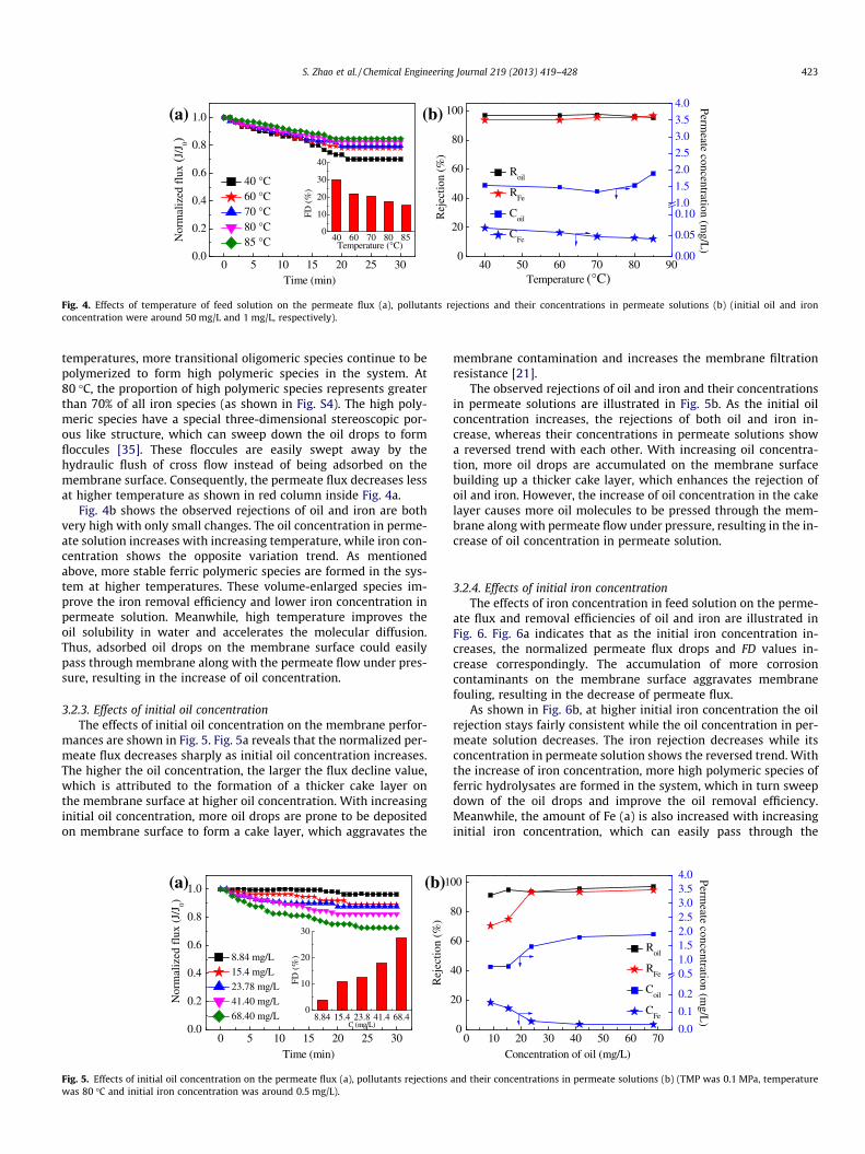
3.2.3. Effects of initial oil concentrationThe effects of initial oil concentration on the membrane perfor-
mances are shown in Fig. 5. Fig. 5a reveals that the normalized per-meate flux decreases sharply as initial oil concentration increases.The higher the oil concentration, the larger the flux decline value,which is attributed to the formation of a thicker cake layer onthe membrane surface at higher oil concentration. With increasinginitial oil concentration, more oil drops are prone to be depositedon membrane surface to form a cake layer, which aggravates the
0 5 10 15 20 25 300.0
0.2
0.4
0.6
0.8
1.0 (b)
8.84 mg/L
15.4 mg/L
23.78 mg/L
41.40 mg/L
68.40 mg/L
Nor
mal
ized
flu
x (J
/J0)
Time (min)
8.84 15.4 23.8 41.4 68.40
10
20
30
FD (
%)
C (mg/L)
1
Rej
ectio
n (%
)
(a)
Fig. 5. Effects of initial oil concentration on the permeate flux (a), pollutants rejectionswas 80 �C and initial iron concentration was around 0.5 mg/L).
membrane contamination and increases the membrane filtrationresistance [21].
The observed rejections of oil and iron and their concentrationsin permeate solutions are illustrated in Fig. 5b. As the initial oilconcentration increases, the rejections of both oil and iron in-crease, whereas their concentrations in permeate solutions showa reversed trend with each other. With increasing oil concentra-tion, more oil drops are accumulated on the membrane surfacebuilding up a thicker cake layer, which enhances the rejection ofoil and iron. However, the increase of oil concentration in the cakelayer causes more oil molecules to be pressed through the mem-brane along with permeate flow under pressure, resulting in the in-crease of oil concentration in permeate solution.
3.2.4. Effects of initial iron concentrationThe effects of iron concentration in feed solution on the perme-
ate flux and removal efficiencies of oil and iron are illustrated inFig. 6. Fig. 6a indicates that as the initial iron concentration in-creases, the normalized permeate flux drops and FD values in-crease correspondingly. The accumulation of more corrosioncontaminants on the membrane surface aggravates membranefouling, resulting in the decrease of permeate flux.
As shown in Fig. 6b, at higher initial iron concentration the oilrejection stays fairly consistent while the oil concentration in per-meate solution decreases. The iron rejection decreases while itsconcentration in permeate solution shows the reversed trend. Withthe increase of iron concentration, more high polymeric species offerric hydrolysates are formed in the system, which in turn sweepdown of the oil drops and improve the oil removal efficiency.Meanwhile, the amount of Fe (a) is also increased with increasinginitial iron concentration, which can easily pass through the
0 10 20 30 40 50 60 700
20
40
60
80
00
Concentration of oil (mg/L)
0.0
0.1
0.2
0.51.01.52.02.53.03.54.0
Roil
RFe
Coil
CFe
Perm
eate concentration (mg/L
)
and their concentrations in permeate solutions (b) (TMP was 0.1 MPa, temperature
0 5 10 15 20 25 300.0
0.2
0.4
0.6
0.8
1.0
0.53 mg/L 1.28 mg/L 3.43 mg/L 4.85 mg/L
Nor
mal
ized
flu
x (J
/J0)
Time (min)
0.53 1.28 3.43 4.850
10
20
30
(b)
FD (
%)
C (mg/L)
(a)
0 1 2 3 4 50
20
40
60
80
100
Concentration of iron (mg/L)
Rej
ectio
n (%
)
0.0
0.5
1.0
1.5
2.0
2.5
3.0
3.5
4.0
Roil
RFe
Coil
CFe
Perm
eate concentration (mg/L
)
Fig. 6. Effects of initial iron concentration on the permeate flux (a), pollutants rejections and their concentrations in permeate solutions (b) (TMP was 0.1 MPa, temperaturewas 80 �C and initial oil concentration was around 50 mg/L).
424 S. Zhao et al. / Chemical Engineering Journal 219 (2013) 419–428
membrane due to the smaller size, resulting in the increase of ironconcentration in permeate solution.
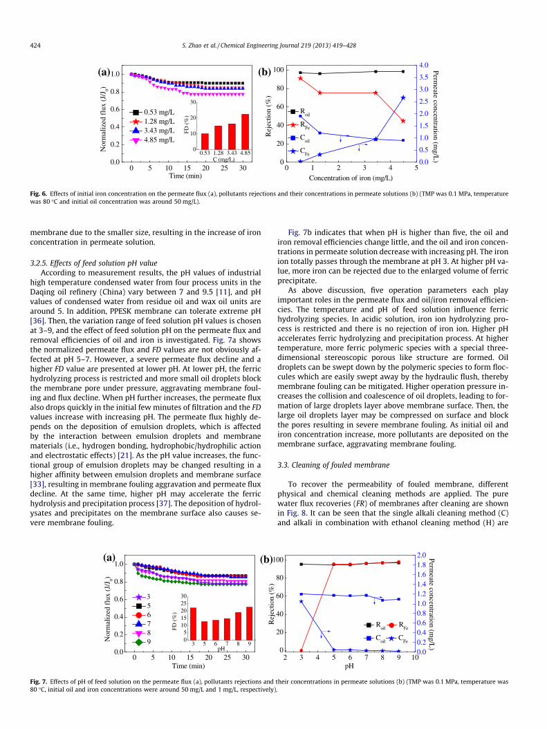
3.2.5. Effects of feed solution pH valueAccording to measurement results, the pH values of industrial
high temperature condensed water from four process units in theDaqing oil refinery (China) vary between 7 and 9.5 [11], and pHvalues of condensed water from residue oil and wax oil units arearound 5. In addition, PPESK membrane can tolerate extreme pH[36]. Then, the variation range of feed solution pH values is chosenat 3–9, and the effect of feed solution pH on the permeate flux andremoval efficiencies of oil and iron is investigated. Fig. 7a showsthe normalized permeate flux and FD values are not obviously af-fected at pH 5–7. However, a severe permeate flux decline and ahigher FD value are presented at lower pH. At lower pH, the ferrichydrolyzing process is restricted and more small oil droplets blockthe membrane pore under pressure, aggravating membrane foul-ing and flux decline. When pH further increases, the permeate fluxalso drops quickly in the initial few minutes of filtration and the FDvalues increase with increasing pH. The permeate flux highly de-pends on the deposition of emulsion droplets, which is affectedby the interaction between emulsion droplets and membranematerials (i.e., hydrogen bonding, hydrophobic/hydrophilic actionand electrostatic effects) [21]. As the pH value increases, the func-tional group of emulsion droplets may be changed resulting in ahigher affinity between emulsion droplets and membrane surface[33], resulting in membrane fouling aggravation and permeate fluxdecline. At the same time, higher pH may accelerate the ferrichydrolysis and precipitation process [37]. The deposition of hydrol-ysates and precipitates on the membrane surface also causes se-vere membrane fouling.
0 5 10 15 20 25 300.0
0.2
0.4
0.6
0.8
1.0
3 5 6 7 8 9N
orm
aliz
ed f
lux
(J/J
0)
Time (min)
3 5 6 7 8 905
1015202530
FD (
%)
pH
1(b)(a)
Rej
ectio
n (%
)
Fig. 7. Effects of pH of feed solution on the permeate flux (a), pollutants rejections and80 �C, initial oil and iron concentrations were around 50 mg/L and 1 mg/L, respectively)
Fig. 7b indicates that when pH is higher than five, the oil andiron removal efficiencies change little, and the oil and iron concen-trations in permeate solution decrease with increasing pH. The ironion totally passes through the membrane at pH 3. At higher pH va-lue, more iron can be rejected due to the enlarged volume of ferricprecipitate.
As above discussion, five operation parameters each playimportant roles in the permeate flux and oil/iron removal efficien-cies. The temperature and pH of feed solution influence ferrichydrolyzing species. In acidic solution, iron ion hydrolyzing pro-cess is restricted and there is no rejection of iron ion. Higher pHaccelerates ferric hydrolyzing and precipitation process. At highertemperature, more ferric polymeric species with a special three-dimensional stereoscopic porous like structure are formed. Oildroplets can be swept down by the polymeric species to form floc-cules which are easily swept away by the hydraulic flush, therebymembrane fouling can be mitigated. Higher operation pressure in-creases the collision and coalescence of oil droplets, leading to for-mation of large droplets layer above membrane surface. Then, thelarge oil droplets layer may be compressed on surface and blockthe pores resulting in severe membrane fouling. As initial oil andiron concentration increase, more pollutants are deposited on themembrane surface, aggravating membrane fouling.
3.3. Cleaning of fouled membrane
To recover the permeability of fouled membrane, differentphysical and chemical cleaning methods are applied. The purewater flux recoveries (FR) of membranes after cleaning are shownin Fig. 8. It can be seen that the single alkali cleaning method (C)and alkali in combination with ethanol cleaning method (H) are
2 3 4 5 6 7 8 9 100
20
40
60
80
00
pH
0.00.20.40.60.81.01.21.41.61.82.0
Roil
RFe
Coil
CFe
Permeate concentration (m
g/L)
their concentrations in permeate solutions (b) (TMP was 0.1 MPa, temperature was.
A B C D E F G H0
20
40
60
80
100F
R (
%)
Cleaning method
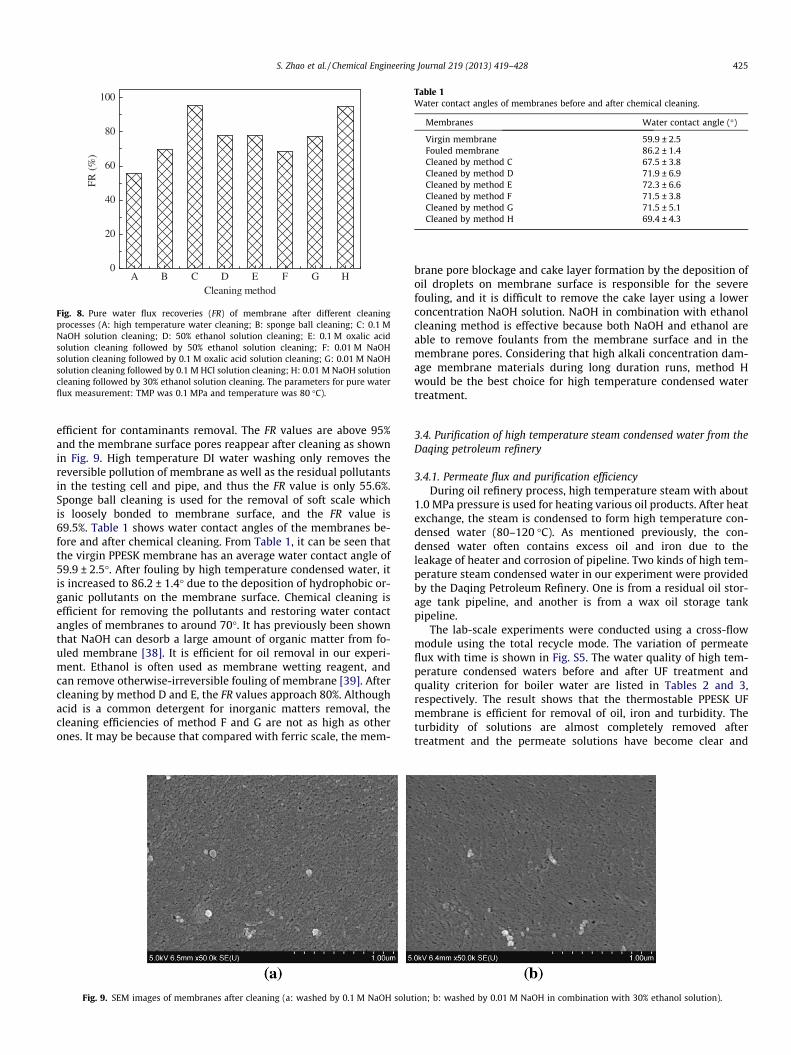
Fig. 8. Pure water flux recoveries (FR) of membrane after different cleaningprocesses (A: high temperature water cleaning; B: sponge ball cleaning; C: 0.1 MNaOH solution cleaning; D: 50% ethanol solution cleaning; E: 0.1 M oxalic acidsolution cleaning followed by 50% ethanol solution cleaning; F: 0.01 M NaOHsolution cleaning followed by 0.1 M oxalic acid solution cleaning; G: 0.01 M NaOHsolution cleaning followed by 0.1 M HCl solution cleaning; H: 0.01 M NaOH solutioncleaning followed by 30% ethanol solution cleaning. The parameters for pure waterflux measurement: TMP was 0.1 MPa and temperature was 80 �C).
Table 1Water contact angles of membranes before and after chemical cleaning.
Membranes Water contact angle (�)
Virgin membrane 59.9 ± 2.5Fouled membrane 86.2 ± 1.4Cleaned by method C 67.5 ± 3.8Cleaned by method D 71.9 ± 6.9Cleaned by method E 72.3 ± 6.6Cleaned by method F 71.5 ± 3.8Cleaned by method G 71.5 ± 5.1Cleaned by method H 69.4 ± 4.3
S. Zhao et al. / Chemical Engineering Journal 219 (2013) 419–428 425
efficient for contaminants removal. The FR values are above 95%and the membrane surface pores reappear after cleaning as shownin Fig. 9. High temperature DI water washing only removes thereversible pollution of membrane as well as the residual pollutantsin the testing cell and pipe, and thus the FR value is only 55.6%.Sponge ball cleaning is used for the removal of soft scale whichis loosely bonded to membrane surface, and the FR value is69.5%. Table 1 shows water contact angles of the membranes be-fore and after chemical cleaning. From Table 1, it can be seen thatthe virgin PPESK membrane has an average water contact angle of59.9 ± 2.5�. After fouling by high temperature condensed water, itis increased to 86.2 ± 1.4� due to the deposition of hydrophobic or-ganic pollutants on the membrane surface. Chemical cleaning isefficient for removing the pollutants and restoring water contactangles of membranes to around 70�. It has previously been shownthat NaOH can desorb a large amount of organic matter from fo-uled membrane [38]. It is efficient for oil removal in our experi-ment. Ethanol is often used as membrane wetting reagent, andcan remove otherwise-irreversible fouling of membrane [39]. Aftercleaning by method D and E, the FR values approach 80%. Althoughacid is a common detergent for inorganic matters removal, thecleaning efficiencies of method F and G are not as high as otherones. It may be because that compared with ferric scale, the mem-
Fig. 9. SEM images of membranes after cleaning (a: washed by 0.1 M NaOH solut
brane pore blockage and cake layer formation by the deposition ofoil droplets on membrane surface is responsible for the severefouling, and it is difficult to remove the cake layer using a lowerconcentration NaOH solution. NaOH in combination with ethanolcleaning method is effective because both NaOH and ethanol areable to remove foulants from the membrane surface and in themembrane pores. Considering that high alkali concentration dam-age membrane materials during long duration runs, method Hwould be the best choice for high temperature condensed watertreatment.
3.4. Purification of high temperature steam condensed water from theDaqing petroleum refinery
3.4.1. Permeate flux and purification efficiencyDuring oil refinery process, high temperature steam with about
1.0 MPa pressure is used for heating various oil products. After heatexchange, the steam is condensed to form high temperature con-densed water (80–120 �C). As mentioned previously, the con-densed water often contains excess oil and iron due to theleakage of heater and corrosion of pipeline. Two kinds of high tem-perature steam condensed water in our experiment were providedby the Daqing Petroleum Refinery. One is from a residual oil stor-age tank pipeline, and another is from a wax oil storage tankpipeline.
The lab-scale experiments were conducted using a cross-flowmodule using the total recycle mode. The variation of permeateflux with time is shown in Fig. S5. The water quality of high tem-perature condensed waters before and after UF treatment andquality criterion for boiler water are listed in Tables 2 and 3,respectively. The result shows that the thermostable PPESK UFmembrane is efficient for removal of oil, iron and turbidity. Theturbidity of solutions are almost completely removed aftertreatment and the permeate solutions have become clear and
ion; b: washed by 0.01 M NaOH in combination with 30% ethanol solution).

Table 2High temperature condensed water quality before and after UF purification.
Residue oil condensed water Wax oil condensed water
Items Influent Effluent Influent EffluentOil concentration (mg/L) 10.8 0.86 8.2 0.13Iron concentration (mg/L) 0.136 0.0386 0.144 0.0295Calcium concentration (mg/L) 1.09 0.515 1.25 0.971Magnesium concentration (mg/L) 0.231 0.179 0.276 0.203Sodium concentration (mg/L) 0.919 0.809 0.868 0.735Conductivity (ls/cm) 9.55 7.22 7.86 5.76Turbidity (NTU) 25.9 0.12 5.08 0.13Hardness(1/2Ca2++1/2Mg2+) (lmol/L) 18.3 10.1 19.9 17.5
Table 3Quality criterion for boiler water [40].
Furnace type Boiler pressure (MPa) Oil concentration (mg/L) Hardness (lmol/L) Iron concentration (lg/L) Conductivity (ls/cm)
Steam drum boiler 3.8–5.8 61 63 650 610
426 S. Zhao et al. / Chemical Engineering Journal 219 (2013) 419–428
transparent. The oil and iron concentrations in the permeate solu-tions are below 1 mg/L and 50 lg/L, respectively, which satisfy theQuality Criterion of Water and Steam for Steam Power Equipment(GB/T 12145-2008, China) listed in Table 2. The hydrolysis and pre-cipitation of iron at high temperature enlarges its volume and thusthe iron can be efficiently retained by membrane. However, the UFmembrane pore size is not small enough to retain other ions, suchas Mg2+, Ca2+ and Na+. Further softening technique or NF mem-brane separation processes are needed to remove hardness andother dissolved ions. For large scale application, the volume of UFretentate stream will be very small and the heating value wouldnot be reclaimed. However, the concentrated retentate solutionmay still be collected to recover oil as fuel using an oil/water sep-arator [23]. Since the iron in the high temperature condensedwater is only produced from the corrosion of pipeline, the iron con-centration is very low. Iron precipitation in the retentate solutionwould be treated as sewage sludge.
3.4.2. Recovery property of PPESK membraneThe excellent reusability of the membrane will provide stable
performance without a significant decline of separation efficiency.Fig. 10 presents the recycling property of PPESK membrane duringwax oil condensed water treatment. After four runs of wax oil con-densed water ultrafiltration, the flux recovery rate is above 90%.The PPESK membrane shows good flux recovery and high temper-ature condensed water can be treated consecutively with a certainmembrane cleaning period.
0 50 100 150 2000
500
1000
1500
2000
2500
3000
FourthThirdSecond
Flux
(L·m
-2·h
-1)
Time (min)
First
Fig. 10. Permeate flux decline over time of PPESK membrane during four runs ofwax oil condensed water ultrafiltration (the filtration parameters: TMP was 0.1 MPaand temperature was 80 �C).
3.4.3. Economic evaluation of future combined UF and NF processes forcondensed water recycling
Suppose the handling capacity of the system is 50 t/h, and thewater recovery rates of UF and NF units are 95% and 90%, respec-tively. The annual operation time is 8400 h. GE Duratherm Excelseries UF and NF membrane modules are applied. The economicevaluation includes economic cost and economic saving.
(1) Economic cost evaluation
� Membrane investments: Fifty UF membrane modulesand seventy NF membrane modules are needed basedon the estimated permeate flows of UF and NF at 1 m3/h and 0.7 m3/h, respectively. One UF membrane modulecosts about $2500 and one NF module costs about$2800. The lifetimes of UF and NF membranes are 3 yearsand 5 years, respectively. Then, membrane investment isestimated at $321,000.
� Mechanical engineering investments: costs for pump,piping, valve system and automatic control system arearound $256,800 (80% of membrane investments).Depreciation period is 15 years.
� Operating costs:– Energy costs: In UF unit, the energy power for one
pump (rated flow: 50 m3/h, lift: 30 m) is 7.5 kW/h.In NF unit, the energy power for three pumps (ratedflow: 100 m3/h, lift: 117 m) are 135 kW/h (The datais provided by Nanfang pump industry Co., Ltd.,China). The power consumption coefficient is 0.7 andthe average commercial power cost in China isapproximately $0.12 [41]. Then, the annual energycost is approximate $100,548.
– Chemicals costs: the annual cost of chemicals is about$15,000.
� Maintenance costs: $5,136 (2% of total mechanical engi-neering investments).
� Labor costs: annual cost of two maintenance workers isabout $7,620.
Then, the total economic cost for the UF and NF processes isestimated at $706,104.
(2) Economic saving evaluation
� Desalination water savingThe effluent flow of NF is calculated as 42.75 t/h based on theabove mentioned assumption. Then, the total reclaimed amount

S. Zhao et al. / Chemical Engineering Journal 219 (2013) 419–428 427
of desalination water per year (M) is 359,100 t. The desalinationwater saving is calculated $574,560 (per ton cost of desalinationwater is $1.6).
� Energy saving
In addition to desalination water saving, the residual heat ofhigh temperature condensed water can also be saved.
The energy that a material absorbs or releases can be calculatedusing the following equation:
Q ¼ CMDT ð4Þ
where Q is the absorbed or released energy (J), C is the specific heatof the material (J kg�1 K�1) (the specific heat of water is4.182 � 103 J kg�1 K�1), M is material mass (kg) and DT is tempera-ture difference (K).
Suppose the effluent temperature of NF is 75 �C, then the resid-ual energy (Q) of reclaimed high temperature condensed water peryear (M) can be calculated using Eq. (4) (room temperature wateris 25 �C).
Q ¼ CMDT ¼ ð4:182� 103Þ � ð3:591� 108Þ � ð75� 25Þ
¼ 7:51� 1013ðJÞ
To obtain the energy shown above, the amount of standard coal(m) is calculated using Eq. (5). Where m is the amount of standardcoal (kg), Q is released energy that complete combustion of the coal(kJ), q is the calorific value of standard coal, namely, 29,274 kJ/kg.
m ¼ Q=q ¼ 7:51� 1010 � 29;274 ¼ 2:565� 106ðkgÞ ð5Þ
If the standard coal price is $79.4 per ton, and then the savedfuel cost is estimated at $203,661.
� CO2 emission reduction saving
Three tons of CO2 will be released by combustion of per ton ofstandard coal. If the entire saved CO2 emission reduction amountis sold according to Clean Development Mechanism (CDM) ($4.8per ton), $12,312 can be saved.
� Sewage discharge fee saving
Suppose the sewage treatment fee is $0.12 per ton, the savedsewage discharge cost is $43,092.
In summary, approximate $833,625 is saved annually byreclaiming the condensed water. Therefore, the breakeven timeof the process is about 11 months.
Table 4Investment and cost comparison of UF process and ‘blocking and intercept’ processfor oil and iron removal ($).
Items ‘Blocking andintercept’ process
Items UFprocess
Iron removalequipmentinvestment
79,400 Membrane modulesinvestment
125,000
Oil removalequipmentinvestment
317,500 Mechanicalengineeringinvestment
100,000
Annual operatingcost
42,000 Annual energy cost 5292
Annual materialsreplacement cost
33300 Annual chemicalscost
3200
Annual maintenancecost
3969 Annual maintenancecost
2000
Annual labor cost 7620 Annual labor cost 7620Per ton cost 0.27 Per ton cost 0.16
3.4.4. Economic comparison of UF process and existing process for oiland iron removal
Now, a ‘blocking and intercept’ oil removal process using fibercoated with strong polarity functional groups is operating in theDaqing petroleum refinery for oil removal of high temperaturecondensed water. The maximum long term influent oil concentra-tion is 150 mg/L, operating temperature is 50–80 �C and pH < 7.5.Raw oil and pitch are forbidden in the system. The investment ofoil removal equipment is estimated at $4,760–6350 per ton perhour, operating cost is about $0.10 per ton. Fiber lifetime is oneyear, and cost for fiber replacement is about $33,300–39,700 everyyear [3]. Another filter tank is required for suspended matter andiron removal prior to oil removal.
Investment and cost comparison of this process and UF processfor oil and iron removal is listed in Table 4. The result shows thatfor depreciation period of 15 years, per ton cost of this processand UF process are approximate $0.27 and $0.16, respectively. UFis a promising and cost-effective process for oil and iron removal.
4. Conclusions
In the present study, the purification and recycling of syntheticand industrial high temperature condensed water from petroleumrefinery with thermostable PPESK UF membrane has been investi-gated. The effects of several important factors on the permeate fluxand oil/iron removal efficiencies have been investigated in detail.The suitable membrane cleaning method was also considered.The economic cost and saving of UF and NF processes was evalu-ated as well. The findings of this study may be summarized asfollows:
(1) In consideration of the permeate flux, removal efficiency andoperation cost, 0.1 MPa is selected as the optimal TMP.Higher feed solution temperature is beneficial to mitigatemembrane fouling and increase the permeate flux. As initialoil and iron concentrations increase, the permeate fluxdecreases due to the aggravated membrane fouling. BetweenpH 5 and 7, permeate flux changes slightly.
(2) NaOH in combination with ethanol cleaning method is effec-tive and the FR value is above 95%.
(3) High temperature condensed water from the Daqing petro-leum refinery can be purified and reclaimed efficiently usingPPESK UF membrane. The turbidity of solution is almostcompletely removed. The oil and iron concentrations in per-meate solutions satisfy the Quality Criterion of Water andSteam for Steam Power Equipment (GB/T 12145-2008,China).
(4) Compared with an existing process, UF, with per ton cost of$0.16, is a promising and cost-effective process for oil andiron removal. For future possible UF and NF processes appli-cation, an estimated $833,625 is saved annually by reclaim-ing the condensed water, and breakeven time is about11 months.
Acknowledgments
This research was supported by the National Science Fund forNational Creative Research Groups of China (50821002). Theauthors acknowledge the Daqing petroleum refinery for providingthe high temperature condensed water. The authors are also verygrateful to Dr. James L. Langer (Serionix, Inc., USA) for revisingthe manuscript; Dr. Jun Wang (Research center for Eco-environ-mental Sciences, Chinese Academy of Sciences, China) for poresize distribution characterization; Xingtao Song (MemSpring

428 S. Zhao et al. / Chemical Engineering Journal 219 (2013) 419–428
Technology Ltd.) and Yunhong Yan (Hangzhou Donan Memtec. Co.,Ltd.) for economic evaluation suggestions.
Appendix A. Supplementary material
Supplementary data associated with this article can be found, inthe online version, at http://dx.doi.org/10.1016/j.cej.2012.12.101.
References
[1] Z.Y. Du, Disquisiton and Application of condensate treatment technique,Master thesis, Tianjing University, Tianjing, 2005, (in Chinese).
[2] H. Yang, G.J. Chen, Q.H. Ma, B.C. Su, Recovery of condensate with hightemperature and cascaded utilization of thermal energy, Energy Conservation1 (2010) 69–73 (In Chinese).
[3] C.Y. Leng, The best solution for removal of iron and oil from hot condensedwater, Adv. Mater. Res. 399–401 (2012) 1079–1083.
[4] S. Li, A process study on energy-saving and economization of steam-condensate water system, Master thesis, Tianjing University, Tianjin, 2006,(in Chinese).
[5] M.E. Varley, British Freshwater Fishes: Factors Affecting Their Distribution,Fishing News, London, 1967.
[6] D. Caissie, The thermal regime of rivers: a review, Freshw. Biol. 51 (2006)1389–1406.
[7] F. Verones, M.M. Hanafiah, S. Pfister, M.A.J. Huijbregts, G.J. Pelletier, A. koehler,Characterization factors for thermal pollution in freshwater aquaticenvironments, Environ. Sci. Technol. 44 (2010) 9364–9369.
[8] R.N. Arieli, A.A. Labin, S. Abramovich, B. Herut, The effect of thermal pollutionon benthic foraminiferal assemblages in the mediterranean shoreface adjacentto Hadera power plant (Israel), Mar. Pollut. Bull. 62 (2011) 1002–1012.
[9] J.W. Zhai, M. Luo, D. Wang, Z.Z. Wu, D.W. Wu, Application of high-temperaturetolerance membrane in condensation water deep purification and treatment,Chem. Ind. Eng. Prog. 28 (2009) 69–71 (In Chinese).
[10] Oil contamination in marine boilers, Aalborg industries, 2001. <http://www.aalborg-industries.com/news_events/documents/3Oilcontaminationinmarineboilers.pdf>.
[11] S.C. Leng, Purifying techniques of condensed water, Ind. Water Treat. 30 (2010)64–67 (In Chinese).
[12] I.O. Vovk, R.K. Melekhov, Role of iron oxide deposits in corrosion damage to thesurfaces of steam-generating tubes of boilers of thermal power plants, Mater.Sci. 31 (1995) 127–130.
[13] K.H. Yeon, J.H. Song, S.H. Moon, A study on stack configuration of continuouselectrodeionization for removal of heavy metal ions from the primary coolantof a nuclear power plant, Water Res. 38 (2004) 1911–1921.
[14] T.T. Lim, X.F. Huang, Evaluation of hydrophobicity/oleophilicity of kapok andits performance in oily water filtration: Comparison of raw and solvent-treated fibers, Ind. Crops Prod. 26 (2007) 125–134.
[15] H. Strathmann, Synthetic membranes and their preparation, NoyesPublications, New Jersey, 1990.
[16] C.M. Coutinho, M.C. Chiu, R.C. Basso, A.P.B. Ribeiro, L.A.G. Gonçalves, L.A.Viotto, State of art of the application of membrane technology to vegetableoils: A review, Food Res. Int. 42 (2009) 536–550.
[17] G. Gutiérrez, A. Lobo, J.M. Benito, J. Coca, C. Pazos, Treatment of a waste oil-in-water emulsion from a copper-rolling process by ultrafiltration and vacuumevaporation, J. Hazard. Mater. 185 (2011) 1569–1574.
[18] M.S.H. Bader, Nanofiltration for oil-fields water injection operations: analysisof concentration polarization, Desalination 201 (2006) 106–113.
[19] S. Norouzbahari, R. Roostaazad, M. Hesampour, Crude oil desalter effluenttreatment by a hybrid UF/RO membrane separation process, Desalination 238(2009) 174–182.
[20] X.S. Yi, W.X. Shi, S.L. Yu, C. Ma, N. Sun, S. Wang, L.M. Jin, L.P. Sun, Optimizationof complex conditions by response surface methodology for APAM–oil/water
emulsion removal from aqua solutions using nano-sized TiO2/Al2O3 PVDFultrafiltration membrane, J. Hazard. Mater. 193 (2011) 37–44.
[21] B. Chakrabarty, A.K. Ghoshal, M.K. Purkait, Ultrafiltration of stable oil-in-wateremulsion by polysulfone membrane, J. Membr. Sci. 325 (2008) 427–437.
[22] B. Chakrabarty, A.K. Ghoshal, M.K. Purkait, Cross-flow ultrafiltration of stableoil-in-water emulsion using polysulfone membranes, Chem. Eng. J. 165 (2010)447–456.
[23] Products and techniques manual of separation membranes, GE powerand water, water and process technologies, <http://www.ge.com/cn/energy/products_and_services/Materials/Process%20Membrane%20Technique%20Brochure.pdf> 2007, (in Chinese).
[24] R.P. Kalakodimi, M.J. Esmacher, Boiler chemistry management usingcoordinated approach of chemicals membranes and online monitoring, GEWater Process Technol. (2009).
[25] Z. Jin, D.L. Yang, S.H. Zhang, X.G. Jian, Preparation and characterization ofpoly(phthalazinone ether sulfone ketone) hollow fiber ultrafiltrationmembrane with high-molecular weight cut-off, J. Membr. Sci. 306 (2007)253–260.
[26] Y.Q. Yang, D.L. Yang, S.H. Zhang, J. Wang, X.G. Jian, Preparation andcharacterization of poly(phthalazinone ether sulfone ketone) hollow fiberultrafiltration membranes with excellent thermal stability, J. Membr. Sci. 280(2006) 957–968.
[27] S.S. Zhao, P. Wang, C. Wang, X. Sun, L.H. Zhang, Thermostable PPESK/TiO2
nanocomposite ultrafiltration membrane for high temperature condensedwater treatment, Desalination 299 (2012) 35–43.
[28] D.Y. Hou, G.H. Dai, J. Wang, H. Fan, L. Zhang, Z.K. Luan, Preparation andcharacterization of PVDF/nonwoven fabric flat-sheet composite membranesfor desalination through direct contact membrane distillation, Sep. Purif.Technol. 101 (2012) 1–10.
[29] G.B. Van Den Berg, C.A. Smolders, Flux decline in ultrafiltration processes,Desalination 77 (1990) 101–133.
[30] L.F. Song, M. Elimelech, Theory of concentration polarization in crossflowfiltration, J. Chem. Soc. Faraday Trans. 91 (1995) 3389–3398.
[31] J.C. Chen, Q.L. Li, M. Elimelech, In situ monitoring techniques for concentrationpolarization and fouling phenomena in membrane filtration, Adv. ColloidInterfac. Sci. 107 (2004) 83–108.
[32] A.B. Koltuniewicz, R.W. Field, Process factors during removal of oil-in-wateremulsions with cross-flow microfiltration, Desalination 105 (1996) 79–89.
[33] X.S. Yi, S.L. Yu, W.X. Shi, N. Sun, L.M. Jin, S. Wang, B. Zhang, C. Ma, L.P. Sun, Theinfluence of important factors on ultrafiltration of oil/water emulsion usingPVDF membrane modified by nano-sized TiO2/Al2O3, Desalination 281 (2011)179–184.
[34] M. Charles, J.R. Flynn, Hydrolysis of inorganic iron (111) salts, Chem. Rev. 84(1984) 31–41.
[35] Y. Yang, P. Wang, Y. Liu, Species distribution of ferric hydrolysates inmicrowave enhanced Fenton-like process and possible mechanism, J.Hazard. Mater. 178 (2010) 293–297.
[36] X.G. Jian, Y. Dai, G.H. He, G.H. Chen, Preparation of UF and NFpoly(phthalazinone ether sulfone ketone) membranes for high temperatureapplication, J. Membr. Sci. 161 (1999) 185–191.
[37] C. Spiteri, P. Regnier, C.P. Slomp, M.A. Charette, pH-dependent iron oxideprecipitation in a subterranean estuary, J. Geochem. Explor. 88 (2006) 399–403.
[38] H. Yamamura, K. Kimura, Y. Watanabe, Mechanism involved in the evolutionof physically irreversible fouling in microfiltration and ultrafiltrationmembranes used for drinking water treatment, Environ. Sci. Technol. 41(2007) 6789–6794.
[39] J.Y. Tian, Z.L. Chen, Y.L. Yang, H. Liang, J. Nan, G.B. Li, Consecutive chemicalcleaning of fouled PVC membrane using NaOH and ethanol duringultrafiltration of river water, Water Res. 44 (2010) 59–68.
[40] Quality Criterion of water and steam for generating unit and steam power,National Standard of the People’s Republic of China (GB/T 12145-+2008), 2008.
[41] Average commercial power price, <http://www.doc88.com/p-807578129672.html> (in Chinese).


![Energy Conversion and Managementkchbi.chtf.stuba.sk/upload_new/file/Miro/Proc... · tillation research is also extended to absorption heat transformer (AHT) [9,10], the reverse operation](https://img.pdfslide.us/doc/110x75/5f05f72a7e708231d4159d5f/energy-conversion-and-tillation-research-is-also-extended-to-absorption-heat-transformer.jpg)


![Applied Thermal Engineeringkchbi.chtf.stuba.sk/upload_new/file/Miro/Proc problemy... · 2017. 3. 12. · RH relative humidity ratio [%] S cross sectional area [m2] T temperature [](https://img.pdfslide.us/doc/110x75/6124f23ea9425612ca0176ff/applied-thermal-problemy-2017-3-12-rh-relative-humidity-ratio-s-cross.jpg)


![Energy and Buildings - stuba.skkchbi.chtf.stuba.sk/upload_new/file/Miro/Proc problemy odovzdane... · applications concentrate on two areas: cement kiln fans [17–22] and mine ventilation](https://img.pdfslide.us/doc/110x75/5e690aa6160ddf70c94ac5b3/energy-and-buildings-stuba-problemy-odovzdane-applications-concentrate-on.jpg)