Embed Size (px)
Citation preview

Important Safety InstructionsRead all warnings and instructions in this manual.Save these instructions. See page 2 for modelnumbers and maximum working pressures.
Instructions
CARBON STEEL
Check–Mate™ 800 PumpsWith Priming Piston and Severe–Duty Rod and Cylinder
Refer to page 2 for Table of Contents.
308351L��
Models 236471
and 246942
Models 237265,
246940 and 246941
ti1447a
Models 198466
and 246938
4990B
04995

2 308351
Table of ContentsList of Models 2. . . . . . . . . . . . . . . . . . . . . . . . . . . . . . . . . . Symbols 3. . . . . . . . . . . . . . . . . . . . . . . . . . . . . . . . . . . . . . Warnings 3. . . . . . . . . . . . . . . . . . . . . . . . . . . . . . . . . . . . . . Installation 6. . . . . . . . . . . . . . . . . . . . . . . . . . . . . . . . . . . . . Operation/Maintenance 12. . . . . . . . . . . . . . . . . . . . . . . . Service
Troubleshooting 17. . . . . . . . . . . . . . . . . . . . . . . . . . . . Required Tools 18. . . . . . . . . . . . . . . . . . . . . . . . . . . . . Disconnecting the Displacement Pump 18. . . . . . . .
Reconnecting the Displacement Pump 19. . . . . . . . Displacement Pump Service 20. . . . . . . . . . . . . . . . .
Parts 28. . . . . . . . . . . . . . . . . . . . . . . . . . . . . . . . . . . . . . . . Technical Data and Performance Chart 38. . . . . . . . . . . Dimensions 49. . . . . . . . . . . . . . . . . . . . . . . . . . . . . . . . . . . Mounting Hole Layout 49. . . . . . . . . . . . . . . . . . . . . . . . . . Graco Standard Warranty 50. . . . . . . . . . . . . . . . . . . . . . Graco Information 50. . . . . . . . . . . . . . . . . . . . . . . . . . . . .
List of Models
Part No. Series Pump Model RatioMaximum Fluid Working Pressure
Maximum Air(or Hydraulic*)Input Pressure
236471 B King� 65:1 40 MPa, 403 bar (5850 psi) 0.6 MPa, 6 bar (90 psi)
237265 B Reduced IcingQuiet King�
65:1 40 MPa, 403 bar (5850 psi) 0.6 MPa, 6 bar (90 psi)
240945 B Quiet King� 65:1 40 MPa, 403 bar (5850 psi) 0.6 MPa, 6 bar (90 psi)
253376 B Quiet King� 65:1 40 MPa, 403 bar (5850 psi) 0.6 MPa, 6 bar (90 psi)
237261 A Bulldog� 31:1 21 MPa, 214 bar (3100 psi) 0.7 MPa, 7 bar (100 psi)
241901 A Bulldog� (55 Gallon/200Liter Size)
31:1 21 MPa, 214 bar (3100 psi) 0.7 MPa, 7 bar (100 psi)
237274 A Reduced IcingQuiet Bulldog�
31:1 21 MPa, 214 bar (3100 psi) 0.7 MPa, 7 bar (100 psi)
237264 A Senator� 19:1 15 MPa, 157 bar (2280 psi) 0.8 MPa, 8.4 bar (120 psi)
198475 A Quiet King� 65:1 40 MPa, 403 bar (5850 psi) 0.6 MPa, 6 bar (90 psi)
198466 A Viscount� II 40 MPa, 403 bar (5850 psi) 10.3 MPa*, 103 bar* (1500 psi*)
246942 A King� 65:1 48 MPa, 483 bar (7000 psi) 0.7 MPa, 7 bar (100 psi)
246940 A Bulldog� 31:1 21 MPa, 214 bar (3100 psi) 0.7 MPa, 7 bar (100 psi)
246941 A Senator� 19:1 15 MPa, 157 bar (2280 psi) 0.8 MPa, 8.4 bar (120 psi)
246938 A Viscount� II 40 MPa, 403 bar (5850 psi) 10.3 MPa*, 103 bar* (1500 psi*)
308351 3
SymbolsWarning Symbol
WARNINGThis symbol alerts you to the possibility of seriousinjury or death if you do not follow the instructions.
Caution Symbol
CAUTIONThis symbol alerts you to the possibility of damage toor destruction of equipment if you do not follow theinstructions.
WARNING
INSTRUCTIONS
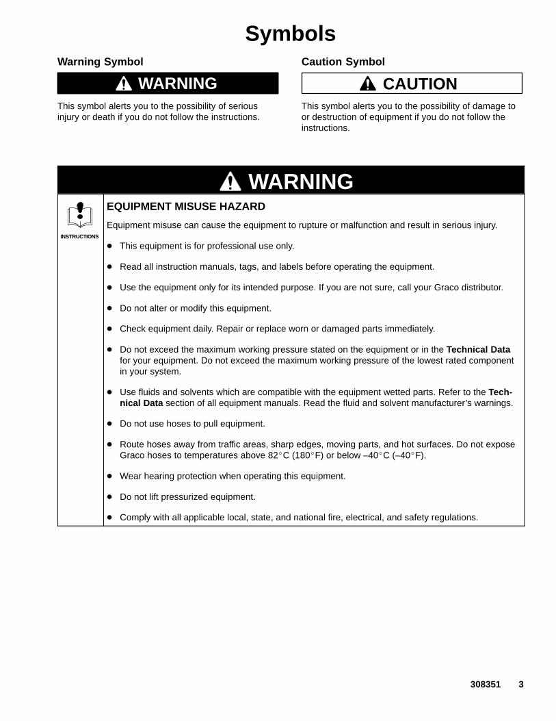
EQUIPMENT MISUSE HAZARD
Equipment misuse can cause the equipment to rupture or malfunction and result in serious injury.
� This equipment is for professional use only.
� Read all instruction manuals, tags, and labels before operating the equipment.
� Use the equipment only for its intended purpose. If you are not sure, call your Graco distributor.
� Do not alter or modify this equipment.
� Check equipment daily. Repair or replace worn or damaged parts immediately.
� Do not exceed the maximum working pressure stated on the equipment or in the Technical Datafor your equipment. Do not exceed the maximum working pressure of the lowest rated componentin your system.
� Use fluids and solvents which are compatible with the equipment wetted parts. Refer to the Tech-nical Data section of all equipment manuals. Read the fluid and solvent manufacturer’s warnings.
� Do not use hoses to pull equipment.
� Route hoses away from traffic areas, sharp edges, moving parts, and hot surfaces. Do not exposeGraco hoses to temperatures above 82�C (180�F) or below –40�C (–40�F).
� Wear hearing protection when operating this equipment.
� Do not lift pressurized equipment.
� Comply with all applicable local, state, and national fire, electrical, and safety regulations.
4 308351
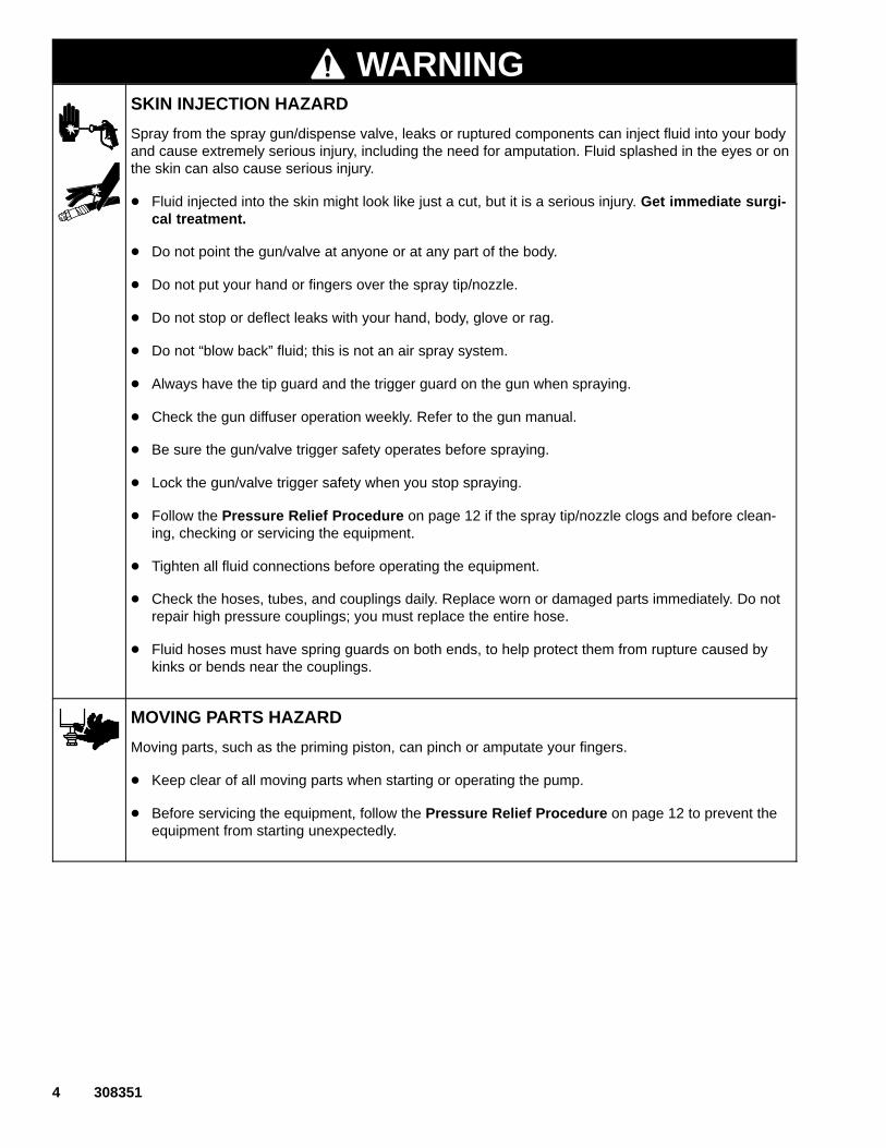
WARNINGSKIN INJECTION HAZARD
Spray from the spray gun/dispense valve, leaks or ruptured components can inject fluid into your bodyand cause extremely serious injury, including the need for amputation. Fluid splashed in the eyes or onthe skin can also cause serious injury.
� Fluid injected into the skin might look like just a cut, but it is a serious injury. Get immediate surgi-cal treatment.
� Do not point the gun/valve at anyone or at any part of the body.
� Do not put your hand or fingers over the spray tip/nozzle.
� Do not stop or deflect leaks with your hand, body, glove or rag.
� Do not “blow back” fluid; this is not an air spray system.
� Always have the tip guard and the trigger guard on the gun when spraying.
� Check the gun diffuser operation weekly. Refer to the gun manual.
� Be sure the gun/valve trigger safety operates before spraying.
� Lock the gun/valve trigger safety when you stop spraying.
� Follow the Pressure Relief Procedure on page 12 if the spray tip/nozzle clogs and before clean-ing, checking or servicing the equipment.
� Tighten all fluid connections before operating the equipment.
� Check the hoses, tubes, and couplings daily. Replace worn or damaged parts immediately. Do notrepair high pressure couplings; you must replace the entire hose.
� Fluid hoses must have spring guards on both ends, to help protect them from rupture caused bykinks or bends near the couplings.
MOVING PARTS HAZARD
Moving parts, such as the priming piston, can pinch or amputate your fingers.
� Keep clear of all moving parts when starting or operating the pump.
� Before servicing the equipment, follow the Pressure Relief Procedure on page 12 to prevent theequipment from starting unexpectedly.

308351 5
WARNINGFIRE AND EXPLOSION HAZARD
Improper grounding, poor ventilation, open flames or sparks can cause a hazardous condition andresult in a fire or explosion and serious injury.
� Ground the equipment and the object being sprayed. Refer to Grounding on page 6.
� If there is any static sparking or you feel an electric shock while using this equipment, stop spray-ing/dispensing immediately. Do not use the equipment until you identify and correct the problem.
� Provide fresh air ventilation to avoid the buildup of flammable fumes from solvents or the fluidbeing sprayed/dispensed.
� Keep the spray/dispense area free of debris, including solvent, rags, and gasoline.
� Electrically disconnect all equipment in the spray/dispense area.
� Extinguish all open flames or pilot lights in the spray/dispense area.
� Do not smoke in the spray/dispense area.
� Do not turn on or off any light switch in the spray/dispense area while operating or if fumes arepresent.
� Do not operate a gasoline engine in the spray/dispense area.
TOXIC FLUID HAZARD
Hazardous fluid or toxic fumes can cause serious injury or death if splashed in the eyes or on the skin,inhaled, or swallowed.
� Know the specific hazards of the fluid you are using.
� Store hazardous fluid in an approved container. Dispose of hazardous fluid according to all local,state and national guidelines.
� Always wear protective eyewear, gloves, clothing and respirator as recommended by the fluid andsolvent manufacturer.
6 308351
InstallationGrounding
WARNINGFIRE AND EXPLOSION HAZARDBefore operating the pump, ground thesystem as explained below. Also readthe section FIRE AND EXPLOSIONHAZARD on page 5.
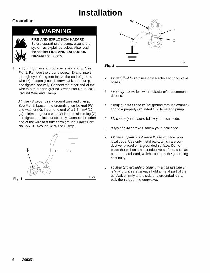
1. King Pumps: use a ground wire and clamp. SeeFig. 1. Remove the ground screw (Z) and insertthrough eye of ring terminal at the end of groundwire (Y). Fasten ground screw back onto pumpand tighten securely. Connect the other end of thewire to a true earth ground. Order Part No. 222011Ground Wire and Clamp.
All other Pumps: use a ground wire and clamp.See Fig. 2. Loosen the grounding lug locknut (W)and washer (X). Insert one end of a 1.5 mm2 (12ga) minimum ground wire (Y) into the slot in lug (Z)and tighten the locknut securely. Connect the otherend of the wire to a true earth ground. Order PartNo. 222011 Ground Wire and Clamp.
Fig. 1 TI1052
YZ
Fig. 2
W
XY
Z
0864
2. Air and fluid hoses: use only electrically conductivehoses.
3. Air compressor: follow manufacturer’s recommen-dations.
4. Spray gun/dispense valve: ground through connec-tion to a properly grounded fluid hose and pump.
5. Fluid supply container: follow your local code.
6. Object being sprayed: follow your local code.
7. All solvent pails used when flushing: follow yourlocal code. Use only metal pails, which are con-ductive, placed on a grounded surface. Do notplace the pail on a nonconductive surface, such aspaper or cardboard, which interrupts the groundingcontinuity.
8. To maintain grounding continuity when flushing orrelieving pressure, always hold a metal part of thegun/valve firmly to the side of a grounded metalpail, then trigger the gun/valve.

308351 7
InstallationAll Systems
NOTE: Reference numbers and letters in parenthesesin the text refer to the callouts in the figures and partsdrawings.
The Typical Installations shown in Figs. 3 and 4 areonly guides for selecting and installing system compo-nents and accessories. Contact your Graco distributorfor assistance in designing a system to suit yourparticular needs.
Accessories are available from Graco. If you supplyyour own accessories, be sure they are adequatelysized and pressure–rated to meet the system’s re-quirements.
System Accessories
Air and Fluid Hoses
Be sure all air hoses and fluid hoses are properly sizedand pressure-rated for your system. Use only electri-cally conductive hoses. Fluid hoses must have springguards on both ends.
Mounting Accessories (Except 198466, 198475 and246938)
Mount the pump (A) to suit the type of installationplanned. Fig. 3 on page 8 illustrates a ram-mountedpump in a multi-gun header system. Pump dimensionsand the mounting hole layout are shown on page 49.
If you are mounting the pump on a ram, refer to theseparate ram manual for installation and operationinstructions. Mounting Kit 222776 is available to mountthe pump on a 55 gallon (200 liter) ram.

8 308351
Installation (Air–Powered Pumps)
05097
Fig. 3
KEY
A PumpB 200 Liter (55 Gallon) Air-Powered RamC Main Air Bleed Valve (required, for pump and ram)D Air Line Lubricator (position only)E Pump Air Bleed Valve (required, for pump)F Pump Air RegulatorG Air ManifoldH Electrically Conductive Air Supply HoseJ Air Line FilterK Air Shutoff Valve (for accessories)L Fluid Regulator
M Fluid Drain Valve (required)N Electrically Conductive Fluid Supply HoseP Fluid Shutoff ValveR Gun/Valve SwivelS Airless Spray Gun or Dispensing ValveT Ram Air RegulatorU Ram Director ValveV Pump Runaway Valve (position only)W Air LIne Drain ValveY Ground Wire (required, see page 6 for
installation instructions)
A
B
CEF
G
H
J K
M
Y
MAIN AIR LINE
R
S
T L
M
N
P
R
S
FLUID HEADER PIPE(3 in. Diameter)
L P
M
N
D
W
U
V
N

308351 9
Installation (Air–Powered Pumps)WARNING
A main air bleed valve (C), pump air bleed valve(E), and fluid drain valve (M) are required. Theseaccessories help reduce the risk of serious injury,including fluid injection and splashing of fluid in theeyes or on the skin, and injury from moving parts ifyou are adjusting or repairing the pump.
The main air bleed valve (C) shuts off the air to thepump and ram. The pump air bleed valve (E)relieves air trapped between this valve and thepump after the air is shut off. Trapped air cancause the pump to cycle unexpectedly. Locate thevalve close to the pump. Order Part No. 107141.
The fluid drain valve assists in relieving fluid pres-sure in the displacement pump, hose, and gun.Triggering the gun to relieve pressure may not besufficient. Order Part No. 210658.
Air Line Accessories
Install the following accessories in the order shown inFig. 3, using adapters as necessary:
� An air line lubricator (D) provides automatic airmotor lubrication. Locate in the position shown.
� A main air bleed valve (C) is required in yoursystem to shut off the air supply to the pump andram (see the WARNING above). When closed, thevalve will bleed off all air in the ram and pump, andthe ram will slowly lower. Be sure the valve is easilyaccessible from the pump, and is located upstreamfrom the air manifold (G).
� A pump air bleed valve (E) is required in yoursystem to relieve air trapped between it and the airmotor when the valve is closed (see the WARNINGat left). Be sure the bleed valve is easily accessiblefrom the pump, and is located downstream fromthe air regulator.
� An air regulator (F) controls pump speed andoutlet pressure by adjusting the air pressure to thepump. Locate the regulator close to the pump, butupstream from the pump air bleed valve.
� A pump runaway valve (V) senses when thepump is running too fast and automatically shuts offthe air to the motor. A pump which runs too fast canbe seriously damaged. Locate in the positionshown.
� An air manifold (G) has a swivel air inlet. Itmounts to a ram, and has ports for connecting linesto air accessories, such as the ram air regulator(T) and ram director valve (U).
� An air line filter (J) removes harmful dirt andmoisture from the compressed air supply. Also,install a drain valve (W) at the bottom of each airline drop, to drain off moisture.
� An air shutoff valve (K) isolates the air line acces-sories for servicing. Locate upstream from all otherair line accessories.
Fluid Line Accessories
Install the following accessories in the positions shownin Figs. 3 and 4, using adapters as necessary:
� Install a fluid shutoff valve (P) at each gun/valvedrop, to isolate the gun/valve and fluid accessoriesfor servicing.
� Install a fluid drain valve (M) near the pump fluidoutlet, and at each gun/valve station. The drainvalves are required in your system to relieve fluidpressure in the displacement pump, hose andgun/valve (see the WARNING at left). Drain valvesat the gun/valve stations may be mounted in thebase of a fluid regulator (L), using an adapter.
� A fluid regulator (L) controls fluid pressure to thegun/valve, and dampens pressure surges.
� A gun or dispense valve (S) dispenses the fluid.The gun shown in Fig. 3 is a high pressure dispens-ing gun for highly viscous fluids.
� A gun/valve swivel (R) allows freer gun/valvemovement.
10 308351
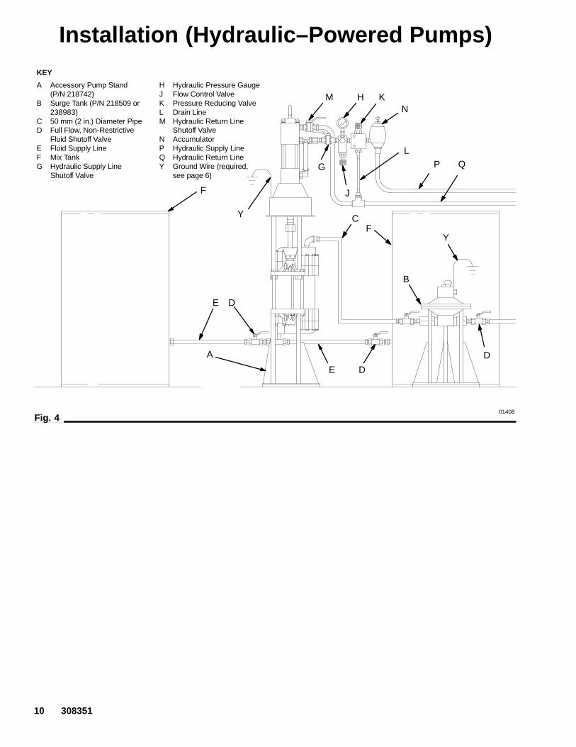
Installation (Hydraulic–Powered Pumps)KEY
A Accessory Pump Stand(P/N 218742)
B Surge Tank (P/N 218509 or238983)
C 50 mm (2 in.) Diameter PipeD Full Flow, Non-Restrictive
Fluid Shutoff ValveE Fluid Supply LineF Mix TankG Hydraulic Supply Line
Shutoff Valve
H Hydraulic Pressure GaugeJ Flow Control ValveK Pressure Reducing ValveL Drain LineM Hydraulic Return Line
Shutoff ValveN AccumulatorP Hydraulic Supply LineQ Hydraulic Return LineY Ground Wire (required,
see page 6)
Fig. 401408
F
E D
A
E D
B
Y
D
F
K
J
L
HM
Y C
N
G P Q

308351 11
Installation (Hydraulic–Powered Pumps)CAUTION
The Hydraulic Power Supply must be kept clean atall times to avoid damage to the motor and hydraulicpower supply.
1. Blow out hydraulic lines with air and flush thor-oughly before connection to the motor.
2. Plug hydraulic inlets, outlets, and line ends whendisconnecting them for any reason.
Always plug the hydraulic inlets, outlets and lines whendisconnecting them for any reason to avoid introducingdirt and other contaminants into the system.
Be sure that your hydraulic power supply is equippedwith a suction filter to the hydraulic pump and a systemreturn line filter of 10 micron size. Carefully follow themanufacturer’s recommendations on reservoir andfilter cleaning and periodic changes of hydraulic fluid.
NOTE: Hydraulic fluid is exhausted from differentialhydraulic motors only on the upstroke of the operatingcycle. The oil return line must have at least twice theflow capacity as the oil supply line. Otherwise, backpressure on the hydraulic motor piston will slow downthe motor and the fluid displacement pump, resulting ina loss of pump performance.
On the hydraulic oil supply line (P), install a shutoffvalve (G) to isolate the system for servicing; a fluidpressure gauge (H) to monitor hydraulic oil pressure tothe motor and avoid overpressurizing the motor ordisplacement pump; a pressure- and temperature-compensated flow control valve (J) to prevent themotor from running too fast; a pressure reducing valve(K) with a drain line (L) running directly into the hydrau-lic return line (Q); and an accumulator (N) to reducethe hammering effect caused by the motor reversingdirection.
On the hydraulic return line (Q), install a shutoff valve(M) for isolating the motor for servicing.

12 308351
OperationPressure Relief Procedure
WARNINGSKIN INJECTION HAZARDThe system pressure must be manuallyrelieved to prevent the system fromstarting or spraying accidentally. Fluid
under high pressure can be injected through theskin and cause serious injury. To reduce the risk ofan injury from injection, splashing fluid, or movingparts, follow the Pressure Relief Procedurewhenever you:
� are instructed to relieve the pressure,� stop spraying/dispensing,� check or service any of the system equipment,� or install or clean the spray tip/nozzle.
1. Lock the gun/valve trigger safety.
2. Shut off the power to the pump.
3. In an air-powered system, close the air regulatorand close the bleed-type master air valve.
4. In a hydraulic-powered system, close the hy-draulic supply line shutoff valve first, then thereturn line shutoff valve.
5. Unlock the gun/valve trigger safety.
6. Hold a metal part of the gun/valve firmly to the sideof a grounded metal pail, and trigger the gun/valveto relieve pressure.
7. Lock the gun/valve trigger safety.
8. In an air–powered system, open the drain valve(required in your system), having a container readyto catch the drainage. Leave the drain valve openuntil you are ready to spray/dispense again.
If you suspect that the spray tip/nozzle or hose iscompletely clogged, or that pressure has not been fullyrelieved after following the steps above, very slowlyloosen the tip guard retaining nut or hose end couplingand relieve pressure gradually, then loosen completely.Now clear the tip/nozzle or hose.
Packing Nut/Wet-CupBefore starting, fill the packing nut (2) 1/3 full withGraco Throat Seal Liquid (TSL) or compatible solvent.See Fig. 5.
WARNINGTo reduce the risk of serious injury whenever youare instructed to relieve pressure, always follow thePressure Relief Procedure at left.
The packing nut is torqued at the factory and is readyfor operation. If it becomes loose and there is leakingfrom the throat packings, relieve pressure, then torquethe nut to 128–156 N.m (95–115 ft-lb) using thesupplied wrench (109). Do this whenever necessary.Do not overtighten the packing nut.
04995
Fig. 5
1Bleed hole must face down.
109
2
129
19
21 2 Torque to 128–156 N.m(95–115 ft-lb).
2
20

308351 13
OperationFlush the Pump Before First Use
The pump is tested with lightweight oil, which is left into protect the pump parts. If the fluid you are usingmay be contaminated by the oil, flush it out with acompatible solvent. See Flushing on page 16.
Starting and Adjusting the Pump
WARNINGMOVING PARTS HAZARDKeep hands and fingers away from thepriming piston (21) during operation andwhenever the pump is charged with air.
The priming piston extends beyond the intakehousing (19) to pull material into the pump and canamputate a hand or finger caught between it andthe intake housing. Follow the Pressure ReliefProcedure on page 12, before checking, clearing,or cleaning the priming piston.
WARNINGSKIN INJECTION HAZARDTo reduce the risk of fluid injection, do not useyour hand or fingers to cover the bleed hole on theunderside of the bleeder valve body (29) whenpriming the pump. Use a crescent wrench to openand close the bleeder plug (20). Keep your handsaway from the bleed hole.
CAUTIONDo not allow the pump to run dry. It will quicklyaccelerate to a high speed, causing damage. If yourpump is running too fast, stop it immediately andcheck the fluid supply. If the container is empty andair has been pumped into the lines, refill the con-tainer and prime the pump and the lines, or flush andleave it filled with a compatible solvent. Eliminate allair from the fluid system.
WARNINGCOMPONENT RUPTURE HAZARDTo reduce the risk of overpressurizingyour system, which could cause compo-nent rupture and serious injury, never
exceed the Maximum Input Pressure to the pump(see the Technical Data on pages 38–46).
Air–Powered Systems
1. Supply fluid to the pump, per the requirements ofyour system.
2. See Fig. 3. Close the air regulator (F).
3. Open all air bleed valves (C, E).
4. Hold a metal part of the gun/valve (S) firmly to theside of a grounded metal pail and hold the triggeropen.
5. Slowly open the air regulator until the pump starts.
6. Cycle the pump slowly until all air is pushed outand the pump and hoses are fully primed.
7. Release the gun/valve trigger and lock the triggersafety. The pump should stall against pressure.
8. If the pump fails to prime properly, open thebleeder valve plug (20) slightly. Use the bleed hole,on the underside of the valve body (29), as apriming valve until the fluid appears at the hole.See Fig. 5. Close the plug.
NOTE: When changing fluid containers with the hoseand gun/valve already primed, open the bleeder valveplug (20), to help prime the pump and vent air before itenters the hose. Close the plug when all air is elimi-nated.
9. With the pump and lines primed, and with ade-quate air pressure and volume supplied, the pumpwill start and stop as you open and close thegun/valve. In a circulating system, the pump willspeed up or slow down on demand, until the airsupply is shut off.
10. Use the air regulator (F) to control the pump speedand the fluid pressure. Always use the lowest airpressure necessary to get the desired results.Higher pressures cause premature tip/nozzle andpump wear.

14 308351
OperationHydraulic–Powered Systems
Refer to the warnings on page 13.
1. Supply fluid to the pump, per the requirements ofyour system.
2. Open the shutoff valves between the pump andsupply tanks.
3. Open the dispensing valve(s) or spray gun(s).
4. To adjust the system, perform the following proce-dure:
a. Turn on the hydraulic power supply.
b. Open the flow control valve all the way.
c. Adjust the pressure–reducing valve until youget the desired fluid pressure. Run the pumpuntil all air is purged from the fluid lines.
d. Count the cycle rate of the pump.
e. Close the flow control valve until the cycle rateand fluid pressure start to drop.
f. Open the flow control valve slightly until thecycle rate and fluid pressure return to thedesired level. This method of setting the hy-draulic controls ensures proper pump opera-tion and will prevent pump runaway and dam-age if the fluid supply runs out.
g. Close the gun or valve.

308351 15
Notes
16 308351
MaintenanceShutdown and Care of the Pump
WARNINGTo reduce the risk of serious injury whenever youare instructed to relieve pressure, always follow thePressure Relief Procedure on page 12.
For overnight shutdown, stop the pump at the bottomof the stroke to prevent fluid from drying on the ex-posed displacement rod and damaging the throatpackings. Relieve the pressure.
Always flush the pump before the fluid dries on thedisplacement rod. Refer to Flushing below.
Flushing
WARNINGFIRE AND EXPLOSION HAZARDBefore flushing, read the section FIREAND EXPLOSION HAZARD on page5. Be sure the entire system and flush-ing pails are properly grounded. Refer toGrounding on page 6.
Flush with a fluid that is compatible with the fluid youare pumping and with the wetted parts in your system.Check with your fluid manufacturer or supplier forrecommended flushing fluids and flushing frequency.Always flush the pump before fluid dries on the dis-placement rod.
CAUTIONNever leave water or water-base fluid in the pumpovernight. If you are pumping water-base fluid, flushwith water first, then with a rust inhibitor such asmineral spirits. Relieve the pressure, but leave therust inhibitor in the pump to protect the parts fromcorrosion.
WARNINGTo reduce the risk of serious injury whenever youare instructed to relieve pressure, always follow thePressure Relief Procedure on page 12.
1. Relieve the pressure.
2. Remove the spray tip/nozzle from the gun/valve.
3. Hold a metal part of the gun/valve firmly to the sideof a grounded metal pail.
4. Start the pump. Always use the lowest possiblefluid pressure when flushing.
5. Trigger the gun/valve.
6. Flush the system until clear solvent flows from thegun/valve.
7. Relieve the pressure.

308351 17
Troubleshooting
WARNINGTo reduce the risk of serious injury whenever youare instructed to relieve pressure, always follow thePressure Relief Procedure on page 12.
1. Relieve the pressure.
2. Check all possible problems and causes beforedisassembling the pump.
PROBLEM CAUSE SOLUTION
Pump fails to operate. Restricted air or hydraulic line or inade-quate air supply; closed or cloggedvalves.
Clear any obstructions; check that all valves areopen; increase pressure.
Obstructed fluid hose or gun/valve;fluid hose ID is too small.
Open, clear*; use a hose with a larger ID.
Fluid dried on the displacement rod. Clean; always stop the pump at the bottom of itsstroke; keep the wet-cup 1/3 filled with a compat-ible solvent.
Dirty, worn, or damaged motor parts. Clean or repair; see the separate motor manual.
Pump operates, butoutput low on bothstrokes.
Restricted air or hydraulic line or inade-quate air supply; closed or cloggedvalves.
Clear any obstructions; check that all valves areopen; increase pressure.
Obstructed fluid hose or gun/valve;fluid hose ID is too small.
Open, clear*; use a hose with a larger ID.
Bleeder valve is open. Close the valve.
Air is leaking into the supply container. Check the ram plate seal.
Fluid is too heavy for pump priming. Use the bleeder valve (see page 13); use a ram.
Held open or worn intake valve or seals. Clear the valve; replace the seals.
Worn packings in the displacementpump.
Replace the packings.
Pump operates, butoutput low on down-stroke.
Fluid too heavy for pump priming. Use the bleeder valve (see page 13); use a ram.
Held open or worn intake valve or seals. Clear the valve; replace the seals.
Pump operates, butoutput low on upstroke.
Held open or worn piston valve or seals. Clear the valve; replace the seals.
THE TROUBLESHOOTING CHART IS CONTINUED ON PAGE 18.
* To determine if the fluid hose or gun is obstructed, follow the Pressure Relief Procedure on page 12. Dis-connect the fluid hose and place a container at the pump fluid outlet to catch any fluid. Turn on the air or hydraulicpower just enough to start the pump. If the pump starts, the obstruction is in the fluid hose or gun.
NOTE: If you experience air motor icing, call your Graco distributor.

18 308351
TroubleshootingPROBLEM CAUSE SOLUTION
Erratic or acceleratedpump speed.
Exhausted fluid supply. Refill and prime.
Fluid is too heavy for pump priming. Use the bleeder valve (see page 13 or 14); use aram.
Held open or worn piston valve or seals. Clear the valve; replace the seals.
Held open or worn priming piston. Clear; service.
Worn packings in the displacementpump.
Replace the packings.
ServiceRequired Tools
� Torque wrench
� Bench vise, with soft jaws
� Rubber mallet
� Hammer
� O-ring pick
� 13 mm (1/2 in.) dia. brass rod
� Set of socket wrenches
� Set of adjustable wrenches
� Pipe wrench
� Packing nut wrench (109, supplied)
� Thread lubricant
� Thread sealant
Disconnecting the Displacement Pump1. Flush the pump, if possible. Stop the pump at the
bottom of its stroke.
WARNINGTo reduce the risk of serious injury whenever youare instructed to relieve pressure, always follow thePressure Relief Procedure on page 12.
2. Relieve the pressure.
3. Disconnect all hoses from the pump and motor.
4. Disconnect the displacement pump (106) from themotor (101) as follows. See Fig. 6. Be sure to notethe relative position of the pump’s fluid outlet (X) tothe motor inlet (Y). If the motor does not requireservicing, leave it attached to its mounting.
CAUTIONBe sure to use at least two people when lifting,moving, or disconnecting the pump. This pump is tooheavy for one person. If you are disconnecting thedisplacement pump from a motor which is stillmounted (for example, on a ram), be sure to supportthe displacement pump while it is being discon-nected, to prevent it from falling and causing injury orproperty damage. Do this by securely bracing thepump, or by having at least two people hold it whileanother disconnects it.
5. Using an adjustable wrench (or a hammer androd), unscrew the coupling nut (104) from themotor shaft (Z). Do not lose or drop the couplingcollars (105). See Fig. 6.
6. Hold the tie rod flats with a wrench to keep therods from turning. Unscrew the nuts (103) from thetie rods (102). Carefully remove the displacementpump (106) from the motor (101).
7. Refer to page 20 for displacement pump service.To service the motor, refer to the separate motormanual, supplied.
308351 19
ServiceReconnecting the Displacement Pump
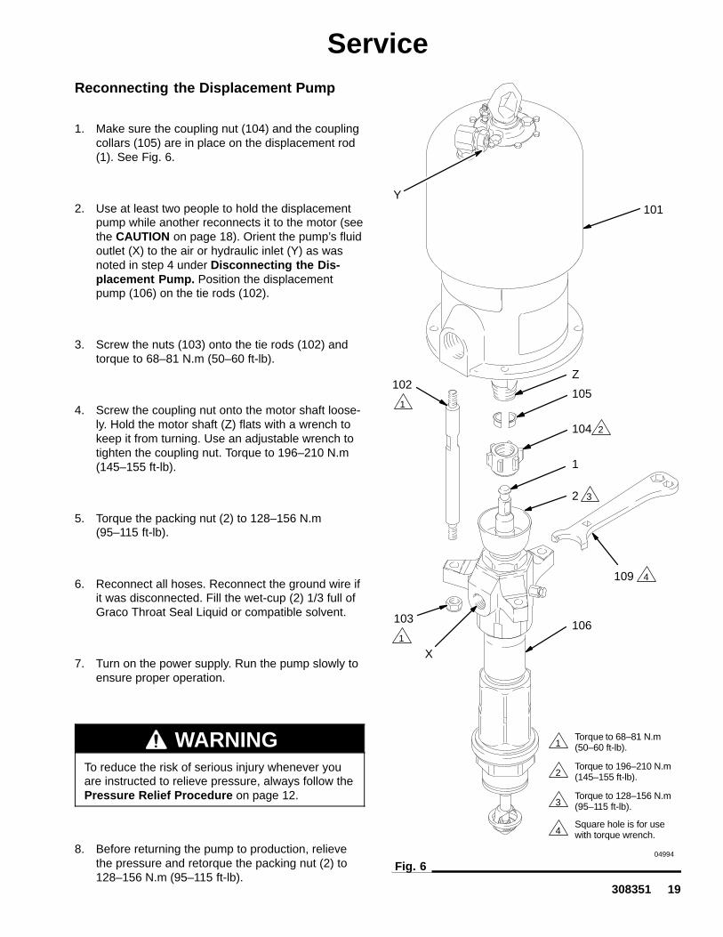
1. Make sure the coupling nut (104) and the couplingcollars (105) are in place on the displacement rod(1). See Fig. 6.
2. Use at least two people to hold the displacementpump while another reconnects it to the motor (seethe CAUTION on page 18). Orient the pump’s fluidoutlet (X) to the air or hydraulic inlet (Y) as wasnoted in step 4 under Disconnecting the Dis-placement Pump. Position the displacementpump (106) on the tie rods (102).
3. Screw the nuts (103) onto the tie rods (102) andtorque to 68–81 N.m (50–60 ft-lb).
4. Screw the coupling nut onto the motor shaft loose-ly. Hold the motor shaft (Z) flats with a wrench tokeep it from turning. Use an adjustable wrench totighten the coupling nut. Torque to 196–210 N.m(145–155 ft-lb).
5. Torque the packing nut (2) to 128–156 N.m(95–115 ft-lb).
6. Reconnect all hoses. Reconnect the ground wire ifit was disconnected. Fill the wet-cup (2) 1/3 full ofGraco Throat Seal Liquid or compatible solvent.
7. Turn on the power supply. Run the pump slowly toensure proper operation.
WARNINGTo reduce the risk of serious injury whenever youare instructed to relieve pressure, always follow thePressure Relief Procedure on page 12.
8. Before returning the pump to production, relievethe pressure and retorque the packing nut (2) to128–156 N.m (95–115 ft-lb).
04994
Fig. 6
1
3
4
2
Torque to 68–81 N.m(50–60 ft-lb).
Torque to 196–210 N.m(145–155 ft-lb).
Torque to 128–156 N.m(95–115 ft-lb).
Square hole is for usewith torque wrench.
101
102105
104
1
2
106103
109
1
1
3
4
2
Z
X
Y

20 308351
Displacement Pump ServiceDisassembly
When disassembling the pump, lay out all the removedparts in sequence, to ease reassembly. Clean all partswith a compatible solvent and inspect them for wear ordamage. Refer to Fig. 9 for a cutaway view of thepump.
NOTE: Packing Repair Kits are available. See page36. For the best results, use all the new parts in the kit.Kit parts are marked with an asterisk, for example (7*).
1. Remove the displacement pump from the motor asexplained on page 18. Place the pump in a vise,with the outlet housing (9) positioned as shown inFig. 8.
2. Hold the flats of the priming piston rod (18) with anadjustable wrench, and use a second wrench tounscrew the priming piston seat (22) from the rod.Slide the priming piston (21) off the rod. Inspectthe inner and outer surfaces of the piston (21) forscoring, wear, or other damage.
3. Loosen the packing nut (2) using the wrench (109)supplied.
4. Using a pipe wrench on the hex of the intakecylinder (19), unscrew it from the intake valvehousing (17). The pump may separate at joints A,B, or C. See Fig. 8.
NOTE: These instructions are written with the pumpseparating at joint A. If it separates at joints B or C,disassemble it at that joint, place the intake housing(17) in a vise, and continue with step 5.
5. Unscrew the intake valve housing (17) from thecylinder (10). Pull the housing off the pump. Theintake check valve assembly (V, see Fig. 7) shouldslide down the priming piston rod (18) as youremove the housing; if it does not slide easily,firmly tap on the top of the housing (17) with arubber mallet to loosen.
05002
Fig. 7
39
17a, b, c
18
38
37 16
15
NP
V
DETAIL OF INTAKE CHECK VALVE
04993
Fig. 8
2
918
2221
1917a, b, c
10
A
B
C
1

308351 21
Displacement Pump Service
Fig. 9
2
3
1
9
20
10
17a, b, c
1918
21
22
8
8
See Fig. 12
See Fig. 7
See Fig. 1029
05002
6. Pull the intake seat (37) and seal (38) out thebottom of the intake valve housing (17). Take carenot to drop the check valve assembly (V) as itcomes free, and set it aside for later. See Fig. 7.
NOTE: If the seat (37) is difficult to remove, insert ahammer and brass rod through the top of the housing(17) and drive the seat out.
7. Using a rubber mallet, drive the displacement rod(1) and the priming piston rod (18) out of the outlethousing (9) and cylinder (10). Inspect the outersurfaces of the rods for damage by running afinger over the surface.
8. Unscrew the packing nut (2). Unscrew the packinghousing (3) and remove the seal (42). Remove thethroat glands and packings (T). See Fig. 10.
42*
Fig. 10
T
2
3
THROAT PACKING DETAIL
05002
Model 236611 Displacement Pump Shown

22 308351
Displacement Pump Service9. Remove the seal (8) from the bottom of the cylin-
der (10). See Fig. 12. Shine a light into the cylinderto examine the inside surface for scoring or dam-age. Only if the cylinder is damaged, or there isevidence of leaking around the top cylinderseal (8), unscrew the cylinder from the outlethousing, using a pipe wrench. Remove the topcylinder seal.
10. Place the flats of the displacement rod (1) in avise. Unscrew the piston (12) from the displace-ment rod; the priming piston rod (18) will comewith it. Slide the piston guide (11) and seat (14) offthe piston (12).
11. It is not necessary to remove the priming pistonrod (18) from the piston (12) unless your inspec-tion reveals damage to either part. To disas-semble, place the piston flats in a vise and un-screw the rod.
12. Place the piston guide (11) in a vise, as shown inFig. 11. Using an adjustable wrench, unscrew thepiston seat (14) from the guide. Remove the seal(13); always replace it with a new one. Inspect themating surfaces (M) of the piston (12) and pistonseat (14) for damage or wear. See Fig. 12.
13. To disassemble the intake check valve assembly(V), place the intake valve body (16) in a vise andunscrew the packing nut (15). Remove the seal(39) from the nut, and the glands and packings (P)from the valve body. Inspect the mating surfaces(N) of the intake valve body (16) and seat (37) fordamage or wear. See Figs. 7 and 13.
NOTE: The seal (39) is press-fit in the nut (15) andmay require cutting to ease removal.
14. Unscrew the bleeder valve plug (20) completelyfrom the valve body (29). Clean the valve threadsand the bleed hole. It is not necessary to removethe valve body from the pump outlet housing (9).
15. Inspect all parts for damage. Clean all parts andthreads with a compatible solvent. Reassemble asexplained on page 23.
03832Fig. 11
1 When reassembling items 11 and 14,apply thread sealant and torque toapprox. 77–85 N.m (57–63 ft-lb).
14
11
Fig. 12
1
11
12
*8
18
10
13*
14
17a, b, cM
1 Torque to 125–139 N.m (92–102 ft-lb).
1
2 Torque to 324–368 N.m (239–271 ft-lb).
2
3 Lubricate.
3
DETAIL OF PISTON CHECK VALVE
3
05002

308351 23
Displacement Pump ServiceReassembly
Fig. 16 shows a cutaway of the entire pump.
1. Lubricate the intake packings and install them inthe valve body (16), with the lips of the v-pack-ings facing up. Install the v-packings in the ordershown in Fig. 13.
2. With the beveled side facing up, press the intakevalve seal (39*) into the recess of the intake valvepacking nut (15) until it snaps into place. The noseof the seal should be flush with or slightly recessedinto the face of the packing nut.
3. Place the flats of the valve body (16) in a vise.Screw the packing nut into the valve body hand-tight. Set the intake housing assembly aside.
4. Lubricate the piston seal (13*) and install it on thepiston seat (14). Apply thread sealant to thethreads of the seat and the piston guide (11).Screw the guide onto the seat (14). Place theguide in a vise as shown in Fig. 11 and torque theseat to 77–85 N.m (57–63 ft-lb).
5. If it was necessary to remove the priming pistonrod (18) from the piston (12), place the flats of thepiston in a vise. Using an adjustable wrench on theflats of the rod, screw the rod into the piston.Torque to 125–139 N.m (92–102 ft-lb). Be carefulnot to create burrs on the flats of the rod.
6. Place the piston seat/guide assembly onto thepiston (12) so the 45� beveled seating surfacesmatch. Screw the displacement rod (1) into thepiston (12) hand tight, then torque the rod to324–368 N.m (239–271 ft-lb).
04225
Fig. 13
1
2
39*
15
Lubricate.
Lips of v-packings must face up. 1 2
1 2
1 2
1 2
23*
26*
24*
24*
25*
16
Model 236611 Displacement Pump Shown
3Optional Displacement Pump 237945uses all PTFE v-packings (item 24).
3
326*
24 308351
Displacement Pump Service7. If the cylinder (10) was removed from the outlet
housing (9), lubricate the seal (8*) and place it onthe top of the cylinder. (The cylinder is symmetri-cal, so either end can be the top.) Screw thecylinder into the outlet housing. See Fig. 16.
8. Lubricate the seal (42*) and install it in the grooveon the bottom of the packing housing (3). Screwthe packing housing into the outlet housing (9) andtorque to 176–258 N.m (130–190 ft-lb). See theDetail in Fig. 16.
9. Lubricate the throat packings and glands, andinstall them in the packing housing (3) one at atime, with the lips of the v-packings facingdown. Install the v-packings in the order shown inthe Detail in Fig. 16. Loosely install the packing nut(2).
10. Lubricate the displacement rod (1). Slide the rod,piston assembly, and priming piston rod (18) intothe cylinder (10) from the bottom, until the top ofthe rod (1) protrudes from the packing nut (2).
11. Lubricate the seal (8*) and install it on the bottomof the cylinder (10). Slide the intake valve housing(17) onto the priming piston rod (18), makingcertain that the smooth surface of the valve stop(VS) is facing down toward the pump intake.Screw the housing onto the cylinder. See Fig. 16.
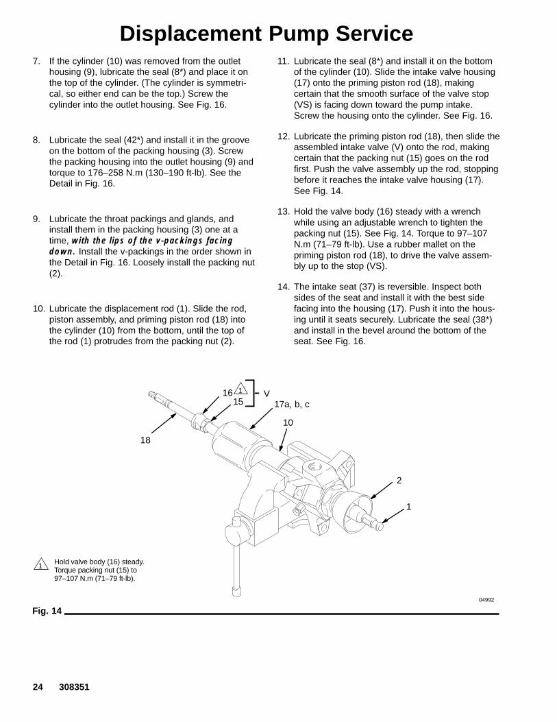
12. Lubricate the priming piston rod (18), then slide theassembled intake valve (V) onto the rod, makingcertain that the packing nut (15) goes on the rodfirst. Push the valve assembly up the rod, stoppingbefore it reaches the intake valve housing (17).See Fig. 14.
13. Hold the valve body (16) steady with a wrenchwhile using an adjustable wrench to tighten thepacking nut (15). See Fig. 14. Torque to 97–107N.m (71–79 ft-lb). Use a rubber mallet on thepriming piston rod (18), to drive the valve assem-bly up to the stop (VS).
14. The intake seat (37) is reversible. Inspect bothsides of the seat and install it with the best sidefacing into the housing (17). Push it into the hous-ing until it seats securely. Lubricate the seal (38*)and install in the bevel around the bottom of theseat. See Fig. 16.
04992
Fig. 14
1 Hold valve body (16) steady.Torque packing nut (15) to97–107 N.m (71–79 ft-lb).
1
17a, b, c
18
1615
V
10
2
1

308351 25
Displacement Pump Service15. Screw the intake cylinder (19) into the intake
housing (17). Using a pipe wrench on the hex ofthe cylinder (19), torque the cylinder to 468–590N.m (345–435 ft-lb). This will also torque the intakevalve housing (17) and pump cylinder (10) into theoutlet housing (9). See Fig. 15.
16. Screw the bleeder valve plug (20) into the valvebody (29). The plug has two sets of threads. Whenreassembling, be sure to screw the plug complete-ly into the valve body. See Fig. 16.
17. Check that the flats of the priming piston rod (18)are accessible below the intake cylinder (19). Ifnot, tap on the top of the displacement rod (1) witha rubber mallet, until the flats are exposed.
18. Slide the priming piston (21) onto the rod (18) untilit stops. Hold the rod (18) steady with an adjust-able wrench on the flats, and screw the seat (22)onto the rod with another wrench. Torque to 77–85N.m (57–63 ft-lb). See Fig.15.
19. Reconnect the displacement pump to the motor asexplained on page 19.
20. Allow 2 hours for the thread sealant to cure beforereturning the pump to service.
04993
2
918
2221
19
17a, b, c10
Fig. 15
1
2 Torque to 468–590 N.m (345–435 ft-lb).
2
1
Torque to 77–85 N.m (57–63 ft-lb).
1

26 308351
Displacement Pump ServiceFor Pumps 198466, 237265 and 236471 only
THROAT PACKING DETAIL
1
3
4
2 Intake check valve (see Fig. 13).
Piston check valve (see Fig. 12).
Screw valve plug (20) completely into valve body (29).5
6
7
Fig. 16
Lips of v-packings must face down.
Torque to 77–85 N.m (57–63 ft-lb).
Torque to 176–258 N.m (130–190 ft-lb).
Torque to 125–139 N.m (92–102 ft-lb).
Torque to 128–156 N.m (95–115 ft-lb).
Torque to 468–590 N.m (345–435 ft-lb).8
10
42*
1
2
3
5*
6*4*
7*
4*6*
6*
1
9
20
10
17a, b, c
1918
21
22
*8
8*
3738*
Lubricate.
3
3
3
1
2
3
VS
3 4
5
8
7
6
10
29
11Optional Displacement Pump 237945uses all PTFE v-packings (item 4).
11
11
11
05002
9
9

308351 27
Displacement Pump ServiceFor Pumps 246938, 246940, 246941 and 246942 only
Servicing the Throat Packings
NOTE: The throat packings are available as a preas-sembled, pre–lubricated kit. For series B pumps, orderPart No. 241782. For series A pumps order Part No.237905. Parts included in these kits are marked withan asterisk, for example (3*). Part No. 237905 includesitems 3, 5 (qty: 1), 6, and 47.
WARNINGTo reduce the risk of serious injury whenever youare instructed to relieve pressure, always follow thePressure Relief Procedure on page12.
1. Relieve the pressure.
2. See Fig. 17. Unscrew the packing nut (2) using apipe wrench. Remove the o-ring (6) and washer(47) from the bottom of the packing housing (3) orfrom the outlet housing (9).
3. Place the flats of the packing nut (2) in a vise.Unscrew the packing housing (3) and discard itand the packings. Remove the washer (46), seal(5), and backup washer (45) from the packing nut.
4. The throat repair kit is preassembled. Screw the kitinto the packing nut (2), making sure that thebackup washer (45*), seal (5*), and washer (46*)are properly positioned on top of the packinghousing (3*), with the lips of the seal facing down.Torque the packing housing (3*) to 97–106 N.m(71–78 ft-lb). See Fig. 17.
5. Check that the washer (47*) and o-ring (6*) areproperly installed on the bottom of the packinghousing (3*).
6. Screw the packing nut (2) into the outlet housing(9). Torque to 190–217 N.m (140–160 ft-lb).
Fig. 17
1
2
2
3*
6*
9
Torque to 97–106 N.m (71–78 ft-lb).
Torque to 190–217 N.m (140–160 ft-lb).
1
2
3 Lips of u-cup packing must face down.
35*
47*
46*
35*
45*
5142C
28 308351
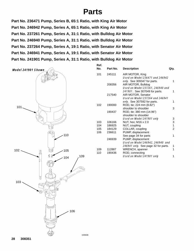
PartsPart No. 236471 Pump, Series B, 65:1 Ratio, with King Air Motor
Part No. 246942 Pump, Series A, 65:1 Ratio, with King Air Motor
Part No. 237261 Pump, Series A, 31:1 Ratio, with Bulldog Air Motor
Part No. 246940 Pump, Series A, 31:1 Ratio, with Bulldog Air Motor
Part No. 237264 Pump, Series A, 19:1 Ratio, with Senator Air Motor
Part No. 246941 Pump, Series A, 19:1 Ratio, with Senator Air Motor
Part No. 241901 Pump, Series A, 31:1 Ratio, with Bulldog Air Motor
101
106
103
105102
104 109
Model 241901 Shown
04994B
110
Ref.No. Part No. Description Qty.
101 245111 AIR MOTOR, KingUsed on Model 236471 and 246942 only. See 309347 for parts. 1
208356 AIR MOTOR, BulldogUsed on Model 237261, 246940 and 241901. See 307049 for parts. 1
217540 AIR MOTOR, SenatorUsed on Model 237264 and 246941 only. See 307592 for parts. 1
102 190000 ROD, tie; 224 mm (8.82”)shoulder to shoulder 3
190437 ROD, tie; 380 mm (14.96”)shoulder to shoulder Used on Model 241901 only 3
103 106166 NUT, hex; M16 x 2.0 3104 186925 NUT, coupling 1105 184129 COLLAR, coupling 2106 236611 PUMP, displacement
See page 34 for parts 1246939 PUMP, displacement
Used on Model 246942, 246940 and246941 only. See page 32 for parts. 1
109 112887 WRENCH, spanner 1110 190436 ROD, connecting
Used on Model 241901 only 1
308351 29
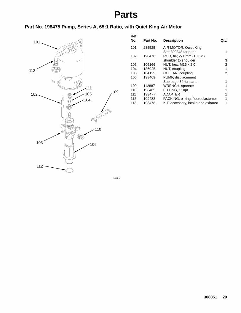
PartsPart No. 198475 Pump, Series A, 65:1 Ratio, with Quiet King Air Motor
ti1449a
101
106103
105102104
109
110
111
113
112
Ref.No. Part No. Description Qty.
101 235525 AIR MOTOR, Quiet KingSee 309348 for parts 1
102 198476 ROD, tie; 271 mm (10.67”)shoulder to shoulder 3
103 106166 NUT, hex; M16 x 2.0 3104 186925 NUT, coupling 1105 184129 COLLAR, coupling 2106 198469 PUMP, displacement
See page 34 for parts 1109 112887 WRENCH, spanner 1110 198465 FITTING, 1” npt 1111 198477 ADAPTER 1112 109482 PACKING, o–ring, fluoroelastomer 1113 198478 KIT, accessory, intake and exhaust 1

30 308351
PartsPart No. 198466 Pump, Series A, with Viscount II Hydraulic Motor
Part No. 246938 Pump, Series A, with Viscount II Hydraulic Motor
ti1446a
101
106
103
105102
104
109
111
112
110
113
Ref.No. Part No. Description Qty.
101 198468 MOTOR, Viscount IISee 307158 for parts 1
102 198471 ROD, tie; 235 mm (9.25”)shoulder to shoulder 3
103 106166 NUT, hex; M16 x 2.0 3104 186925 NUT, coupling 1105 184129 COLLAR, grounding 2106 198469 PUMP, displacement
Used on Model 198466 only.See page 34 for parts 1
246939 PUMP, displacementUsed on Model 246938 only.See page 32 for parts 1
109 112887 WRENCH, spanner 1110 198473 FITTING, reducer 1111 198472 FITTING, reducer 1112 198465 FITTING, 1” npt 1113 109482 PACKING, o–ring, fluoroelastomer 1
308351 31
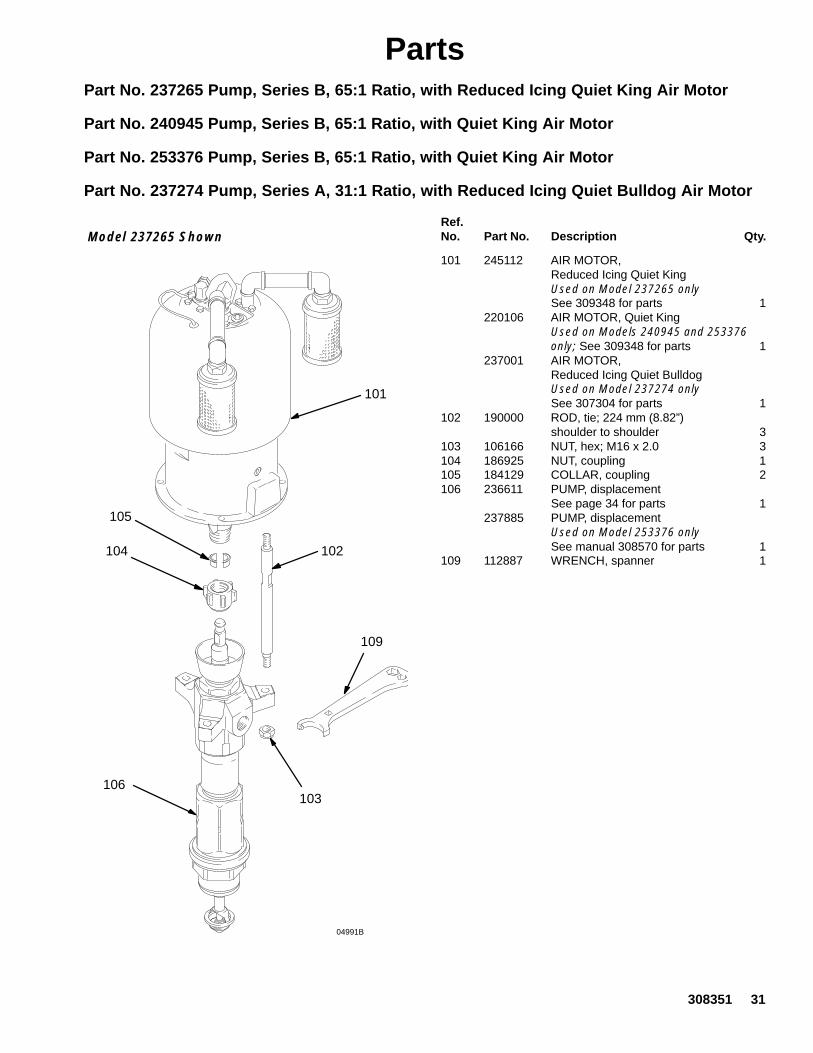
PartsPart No. 237265 Pump, Series B, 65:1 Ratio, with Reduced Icing Quiet King Air Motor
Part No. 240945 Pump, Series B, 65:1 Ratio, with Quiet King Air Motor
Part No. 253376 Pump, Series B, 65:1 Ratio, with Quiet King Air Motor
Part No. 237274 Pump, Series A, 31:1 Ratio, with Reduced Icing Quiet Bulldog Air Motor
Model 237265 Shown
04991B
101
106
102104
109
103
105
Ref.No. Part No. Description Qty.
101 245112 AIR MOTOR, Reduced Icing Quiet KingUsed on Model 237265 onlySee 309348 for parts 1
220106 AIR MOTOR, Quiet KingUsed on Models 240945 and 253376 only; See 309348 for parts 1
237001 AIR MOTOR, Reduced Icing Quiet BulldogUsed on Model 237274 onlySee 307304 for parts 1
102 190000 ROD, tie; 224 mm (8.82”)shoulder to shoulder 3
103 106166 NUT, hex; M16 x 2.0 3104 186925 NUT, coupling 1105 184129 COLLAR, coupling 2106 236611 PUMP, displacement
See page 34 for parts 1237885 PUMP, displacement
Used on Model 253376 onlySee manual 308570 for parts 1
109 112887 WRENCH, spanner 1
32 308351
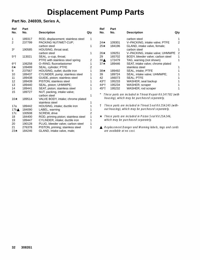
Displacement Pump PartsPart No. 246939, Series A,
Ref PartNo. No. Description Qty
Ref PartNo. No. Description Qty
1 189317 ROD, displacement; stainless steel 12 237799 PACKING NUT/WET-CUP;
carbon steel 13* 190585 HOUSING, throat seal;
carbon steel 15*� 113021 SEAL, u–cup, throat;
PTFE with stainless steel spring 26*� 106258 O–RING; fluoroelastomer 18� 109499 SEAL, cylinder; PTFE 29 237567 HOUSING, outlet; ductile iron 110 189437 CYLINDER, pump; stainless steel 111 189438 GUIDE, piston; stainless steel 112 189439 PISTON; stainless steel 113 189440 SEAL, piston; UHMWPE; 114 189441 SEAT, piston; stainless steel 115 189727 NUT, packing, intake valve;
carbon steel 116� 189514 VALVE BODY, intake; chrome plated
stainless steel 117a 189442 HOUSING, intake; ductile iron 117b� 184090 LABEL, warning 117c 100508 SCREW, drive 218 184400 ROD, priming piston; stainless steel 119 189447 CYLINDER, intake; ductile iron 120 190128 PLUG, bleeder valve; carbon steel 121 276378 PISTON, priming; stainless steel 123� 184246 GLAND, intake valve, male;
carbon steel 124� 109301 V–PACKING, intake valve; PTFE 225� 184196 GLAND, intake valve, female;
carbon steel 126� 109251 V–PACKING, intake valve; UHMWPE 229 165702 BODY, bleeder valve; carbon steel 130� 172479 TAG, warning (not shown) 137� 189446 SEAT, intake valve; chrome plated
stainless steel 138� 189492 SEAL, intake; PTFE 139 189724 SEAL, intake valve; UHMWPE; 142 166073 SEAL; PTFE 143*� 195233 WASHER; seal backup 144*� 195234 WASHER; scraper 145*� 195232 WASHER; rod scraper 1
* These parts are included in Throat Repair Kit 241782 (withhousing), which may be purchased separately.
� These parts are included in Throat Seal Kit 25A245 (with-out housing), which may be purchased separately.
� These parts are included in Piston Seal Kit 25A246,which may be purchased separately.
� Replacement Danger and Warning labels, tags and cardsare available at no cost.

308351 33
Displacement Pump Parts
04989
2
1
*3
8
9
10
11
12
13
14
15
16
17a, b, c
18
19
21
22
29
37
38
39
*620
*5
*44
*5
*43
*45
23
25
2624
34 308351
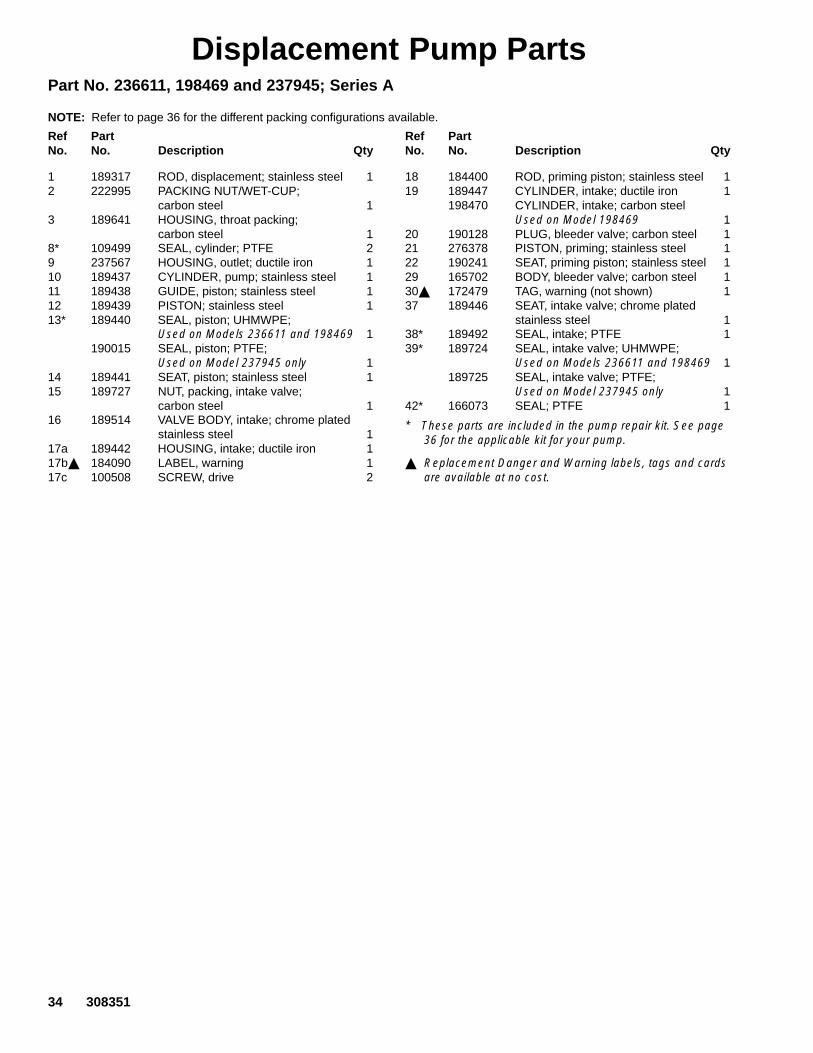
Displacement Pump PartsPart No. 236611, 198469 and 237945; Series A
NOTE: Refer to page 36 for the different packing configurations available.
Ref PartNo. No. Description Qty
Ref PartNo. No. Description Qty
1 189317 ROD, displacement; stainless steel 12 222995 PACKING NUT/WET-CUP;
carbon steel 13 189641 HOUSING, throat packing;
carbon steel 18* 109499 SEAL, cylinder; PTFE 29 237567 HOUSING, outlet; ductile iron 110 189437 CYLINDER, pump; stainless steel 111 189438 GUIDE, piston; stainless steel 112 189439 PISTON; stainless steel 113* 189440 SEAL, piston; UHMWPE;
Used on Models 236611 and 198469 1190015 SEAL, piston; PTFE;
Used on Model 237945 only 114 189441 SEAT, piston; stainless steel 115 189727 NUT, packing, intake valve;
carbon steel 116 189514 VALVE BODY, intake; chrome plated
stainless steel 117a 189442 HOUSING, intake; ductile iron 117b� 184090 LABEL, warning 117c 100508 SCREW, drive 2
18 184400 ROD, priming piston; stainless steel 119 189447 CYLINDER, intake; ductile iron 1
198470 CYLINDER, intake; carbon steelUsed on Model 198469 1
20 190128 PLUG, bleeder valve; carbon steel 121 276378 PISTON, priming; stainless steel 122 190241 SEAT, priming piston; stainless steel 129 165702 BODY, bleeder valve; carbon steel 130� 172479 TAG, warning (not shown) 137 189446 SEAT, intake valve; chrome plated
stainless steel 138* 189492 SEAL, intake; PTFE 139* 189724 SEAL, intake valve; UHMWPE;
Used on Models 236611 and 198469 1189725 SEAL, intake valve; PTFE;
Used on Model 237945 only 142* 166073 SEAL; PTFE 1
* These parts are included in the pump repair kit. See page36 for the applicable kit for your pump.
� Replacement Danger and Warning labels, tags and cardsare available at no cost.

308351 35
Displacement Pump Parts
04989
2
1
3
*8
9
10
11
12
*13
14
15
16
17a, b, c
18
19
21
22
29
37
38*
39*
*42
20
ThroatPacking Stack.
See page 36.
IntakePacking Stack.See page 36.

36 308351
Displacement Pump Parts
Part No. 236611 and 198469, Series A,Standard UHMWPE/PTFE Packed Displacement Pump
Ref PartNo. No. Description Qty
4* 109306 V-PACKING, throat; PTFE 25* 184201 GLAND, throat, female; carbon steel 16* 109256 V-PACKING, throat; UHMWPE 37* 184251 GLAND, throat, male; carbon steel 123* 184246 GLAND, intake valve, male;
carbon steel 124* 109301 V-PACKING, intake valve; PTFE 225* 184196 GLAND, intake valve, female;
carbon steel 126* 109251 V-PACKING, intake valve; UHMWPE 2
* These parts are included in Repair Kit 222864, which maybe purchased separately. See page 34 for additional partsincluded in the kit.
THROAT PACKINGS:LIPS FACE DOWN
INTAKE PACKINGS:LIPS FACE UP
LUBRICATE PACKINGS
4*
*5
*6
*7
*23
24**25
*26
04989
Part No. 237945, Series A, Optional PTFE Packed Displacement Pump
Ref PartNo. No. Description Qty
4* 109306 V-PACKING, throat; PTFE 55* 184201 GLAND, throat, female; carbon steel 17* 184251 GLAND, throat, male; carbon steel 123* 184246 GLAND, intake valve, male;
carbon steel 124* 109301 V-PACKING, intake valve; PTFE 425* 184196 GLAND, intake valve, female;
carbon steel 1
THROAT PACKINGS:LIPS FACE DOWN
INTAKE PACKINGS:LIPS FACE UP
LUBRICATE PACKINGS*5
*4
*7
*23
*25
*24
04989
* These parts are included in Repair Kit 222865, which maybe purchased separately. See page 34 for additional partsincluded in the kit.

308351 37
Notes
38 308351
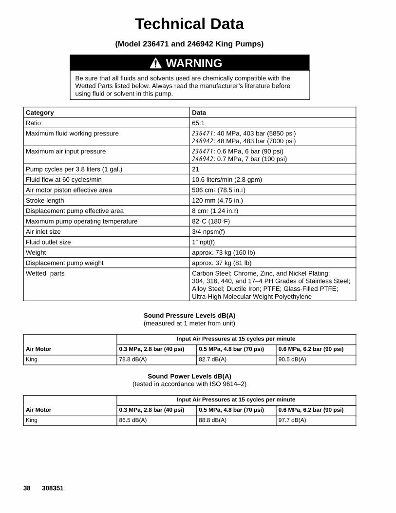
Technical Data(Model 236471 and 246942 King Pumps)
WARNINGBe sure that all fluids and solvents used are chemically compatible with theWetted Parts listed below. Always read the manufacturer’s literature beforeusing fluid or solvent in this pump.
Category Data
Ratio 65:1
Maximum fluid working pressure 236471: 40 MPa, 403 bar (5850 psi) 246942: 48 MPa, 483 bar (7000 psi)
Maximum air input pressure 236471: 0.6 MPa, 6 bar (90 psi)246942: 0.7 MPa, 7 bar (100 psi)
Pump cycles per 3.8 liters (1 gal.) 21
Fluid flow at 60 cycles/min 10.6 liters/min (2.8 gpm)
Air motor piston effective area 506 cm (78.5 in.)
Stroke length 120 mm (4.75 in.)
Displacement pump effective area 8 cm (1.24 in.)
Maximum pump operating temperature 82�C (180�F)
Air inlet size 3/4 npsm(f)
Fluid outlet size 1” npt(f)
Weight approx. 73 kg (160 lb)
Displacement pump weight approx. 37 kg (81 lb)
Wetted parts Carbon Steel; Chrome, Zinc, and Nickel Plating; 304, 316, 440, and 17–4 PH Grades of Stainless Steel;Alloy Steel; Ductile Iron; PTFE; Glass-Filled PTFE;Ultra-High Molecular Weight Polyethylene
Sound Pressure Levels dB(A)(measured at 1 meter from unit)
Input Air Pressures at 15 cycles per minute
Air Motor 0.3 MPa, 2.8 bar (40 psi) 0.5 MPa, 4.8 bar (70 psi) 0.6 MPa, 6.2 bar (90 psi)
King 78.8 dB(A) 82.7 dB(A) 90.5 dB(A)
Sound Power Levels dB(A)(tested in accordance with ISO 9614–2)
Input Air Pressures at 15 cycles per minute
Air Motor 0.3 MPa, 2.8 bar (40 psi) 0.5 MPa, 4.8 bar (70 psi) 0.6 MPa, 6.2 bar (90 psi)
King 86.5 dB(A) 88.8 dB(A) 97.7 dB(A)

308351 39
Technical Data(Model 236471 and 246942 King Pumps)
To find Fluid Outlet Pressure (psi/MPa/bar) at a specific fluid flow(lpm/gpm) and operating air pressure (psi/MPa/bar):
1. Locate desired flow along bottom of chart.
2. Follow vertical line up to intersection with selected fluid outletpressure curve (black). Follow left to scale to read fluid outletpressure.
To find Pump Air Consumption (m/min or scfm) at a specific fluidflow (lpm/gpm) and air pressure (psi/MPa/bar):
1. Locate desired flow along bottom of chart.
2. Read vertical line up to intersection with selected air consumptioncurve (dashes). Follow left to scale to read air consumption.
A 0.6 MPa, 6.2 bar (90 psi) air pressure B 0.5 MPa, 4.9 bar (70 psi) air pressureC 0.3 MPa, 2.8 bar (40 psi) air pressure
Performance Charts
0
2000
4000
6000
0 1 2 3
Fluid Outlet Pressure
21 42 63psi
MPa, barcycles per minute
gpmliters/minute 3.8 7.6 11.4
FL
UID
PR
ES
SU
RE
42, 420
28, 280
14, 140
A
B
C
0
100
200
300
0 1 2 3
Air Consumption
21 42 63scfmm/min
cycles per minute
gpmliters/minute 3.8 7.6 11.4
AIR
CO
NS
UM
PT
ION
A
B
C
8.40
5.60
2.80
0
2000
4000
6000
0 1 2 3
Fluid Outlet Pressure
21 42 63psi
MPa, barcycles per minute
gpmliters/minute 3.8 7.6 11.4
FL
UID
PR
ES
SU
RE
42, 420
28, 280
14, 140
A
B
C
0
100
200
300
0 1 2 3
Air Consumption
21 42 63scfmm/min
cycles per minute
gpmliters/minute 3.8 7.6 11.4
AIR
CO
NS
UM
PT
ION
A
B
C
8.40
5.60
2.80
Test Fluid: No. 10 Weight Oil
Test Fluid: 4 Million CPS Weldable Rubber Base Sealer

40 308351
Technical Data(Models 240945, 253376, and 198475 Quiet King Pump and
Model 237265 Reduced Icing Quiet King Pump)
WARNINGBe sure that all fluids and solvents used are chemically compatible with theWetted Parts listed below. Always read the manufacturer’s literature beforeusing fluid or solvent in this pump.
Category Data
Ratio 65:1
Maximum fluid working pressure 40 MPa, 403 bar (5850 psi)
Maximum air input pressure 0.6 MPa, 6 bar (90 psi)
Pump cycles per 3.8 liters (1 gal.) 21
Fluid flow at 60 cycles/min 10.6 liters/min (2.8 gpm)
Air motor piston effective area 506 cm (78.5 in.)
Stroke length 120 mm (4.75 in.)
Displacement pump effective area 8 cm (1.24 in.)
Maximum pump operating temperature 82�C (180�F)
Air inlet size Models 240945, 253376, and 237265: 3/4 npsm(f)Model 198475: G1/2
Fluid outlet size 1” npt(f)
Weight approx. 73 kg (160 lb)
Displacement pump weight approx. 37 kg (81 lb)
Wetted parts Carbon Steel; Chrome, Zinc, and Nickel Plating; 304, 316, 440, and 17–4 PH Grades of Stainless Steel;Alloy Steel; Ductile Iron; PTFE; Glass-Filled PTFE;Ultra-High Molecular Weight PolyethyleneModel 253376: See manual 308570
Sound Pressure Levels dB(A)(measured at 1 meter from unit)
Input Air Pressures at 15 cycles per minute
Air Motor 0.3 MPa, 2.8 bar (40 psi) 0.5 MPa, 4.8 bar (70 psi) 0.6 MPa, 6.2 bar (90 psi)
Quiet King 77.9 dB(A) 79.2 dB(A) 87.5 dB(A)
Sound Power Levels dB(A)(tested in accordance with ISO 9614–2)
Input Air Pressures at 15 cycles per minute
Air Motor 0.3 MPa, 2.8 bar (40 psi) 0.5 MPa, 4.8 bar (70 psi) 0.6 MPa, 6.2 bar (90 psi)
Quiet King 85.2 dB(A) 86.6 dB(A) 95.2 dB(A)

308351 41
Technical Data(Models 240945, 253376, and 198475 Quiet King Pump and
Model 237265 Reduced Icing Quiet King Pump)
To find Fluid Outlet Pressure (psi/MPa/bar) at a specific fluid flow(lpm/gpm) and operating air pressure (psi/MPa/bar):
1. Locate desired flow along bottom of chart.
2. Follow vertical line up to intersection with selected fluid outletpressure curve (black). Follow left to scale to read fluid outletpressure.
To find Pump Air Consumption (m/min or scfm) at a specific fluidflow (lpm/gpm) and air pressure (psi/MPa/bar):
1. Locate desired flow along bottom of chart.
2. Read vertical line up to intersection with selected air consumptioncurve (dashes). Follow left to scale to read air consumption.
A 0.6 MPa, 6.2 bar (90 psi) air pressure B 0.5 MPa, 4.9 bar (70 psi) air pressureC 0.3 MPa, 2.8 bar (40 psi) air pressure
Performance Charts
0
2000
4000
6000
0 1 2 3
Fluid Outlet Pressure
21 42 63psi
MPa, barcycles per minute
gpmliters/minute 3.8 7.6 11.4
FL
UID
PR
ES
SU
RE
42, 420
28, 280
14, 140
A
B
C
0
100
200
300
0 1 2 3
Air Consumption
21 42 63scfmm/min
cycles per minute
gpmliters/minute 3.8 7.6 11.4
AIR
CO
NS
UM
PT
ION
A
B
C
8.40
5.60
2.80
0
2000
4000
6000
0 1 2 3
Fluid Outlet Pressure
21 42 63psi
MPa, barcycles per minute
gpmliters/minute 3.8 7.6 11.4
FL
UID
PR
ES
SU
RE
42, 420
28, 280
14, 140
A
B
C
0
100
200
300
0 1 2 3
Air Consumption
21 42 63scfmm/min
cycles per minute
gpmliters/minute 3.8 7.6 11.4
AIR
CO
NS
UM
PT
ION
ABC
8.40
5.60
2.80
Test Fluid: No. 10 Weight Oil
Test Fluid: 4 Million CPS Weldable Rubber Base Sealer

42 308351
Technical Data(Model 237261, 246940 and 241901 Bulldog Pumps)
WARNINGBe sure that all fluids and solvents used are chemically compatible with theWetted Parts listed below. Always read the manufacturer’s literature beforeusing fluid or solvent in this pump.
Category Data
Ratio 31:1
Maximum fluid working pressure 21 MPa, 214 bar (3100 psi)
Maximum air input pressure 0.7 MPa, 7 bar (100 psi)
Pump cycles per 3.8 liters (1 gal.) 21
Fluid flow at 60 cycles/min 10.6 liters/min (2.8 gpm)
Air motor piston effective area 248 cm (38 in.)
Stroke length 120 mm (4.75 in.)
Displacement pump effective area 8 cm (1.24 in.)
Maximum pump operating temperature 82�C (180�F)
Air inlet size 3/4 npsm(f)
Fluid outlet size 1” npt(f)
Weight approx. 73 kg (160 lb)
Displacement pump weight approx. 37 kg (81 lb)
Wetted parts Carbon Steel; Chrome, Zinc, and Nickel Plating; 304, 316, 440, and 17–4 PH Grades of Stainless Steel;Alloy Steel; Ductile Iron; PTFE; Glass-Filled PTFE;Ultra-High Molecular Weight Polyethylene
Sound Pressure Levels dB(A)(measured at 1 meter from unit)
Input Air Pressures at 15 cycles per minute
Air Motor0.28 MPa, 2.8 bar (40 psi)
0.48 MPa, 4.8 bar (70 psi)
0.63 MPa, 6.3 bar (90 psi)
0.7 MPa, 7 bar (100 psi)
Bulldog 82.4 dB(A) 87.3 dB(A) 88.5 dB(A) 90.0 dB(A)
Sound Power Levels dB(A)(tested in accordance with ISO 9614–2)
Input Air Pressures at 15 cycles per minute
Air Motor0.28 MPa, 2.8 bar (40 psi)
0.48 MPa, 4.8 bar (70 psi)
0.63 MPa, 6.3 bar (90 psi)
0.7 MPa, 7 bar (100 psi)
Bulldog 91.6 dB(A) 95.9 dB(A) 97.4 dB(A) 98.1 dB(A)

308351 43
Technical Data(Model 237261, 246940 and 241901 Bulldog Pump)
To find Fluid Outlet Pressure (psi/MPa/bar) at a specific fluid flow(lpm/gpm) and operating air pressure (psi/MPa/bar):
1. Locate desired flow along bottom of chart.
2. Follow vertical line up to intersection with selected fluid outletpressure curve (black). Follow left to scale to read fluid outletpressure.
To find Pump Air Consumption (m/min or scfm) at a specific fluidflow (lpm/gpm) and air pressure (psi/MPa/bar):
1. Locate desired flow along bottom of chart.
2. Read vertical line up to intersection with selected air consumptioncurve (dashes). Follow left to scale to read air consumption.
A 0.7 MPa, 7 bar (100 psi) air pressure B 0.5 MPa, 4.9 bar (70 psi) air pressureC 0.3 MPa, 2.8 bar (40 psi) air pressure
Performance Charts
0
1000
2000
3000
0 1 2 3
Fluid Outlet Pressure
21 42 63psi
MPa, barcycles per minute
gpmliters/minute 3.8 7.6 11.4
FL
UID
PR
ES
SU
RE
21, 210
14, 140
7, 70
A
B
C
0
50
100
150
0 1 2 3
Air Consumption
21 42 63scfmm/min
cycles per minute
gpmliters/minute 3.8 7.6 11.4
AIR
CO
NS
UM
PT
ION
A
B
C
4.20
2.80
1.40
0
1000
2000
3000
0.0 0.5 1.0 1.5 2.0 2.5
Fluid Outlet Pressure
20 40 50psi
MPa, barcycles per minute
gpmliters/minute 3.8 7.6 9.5
FL
UID
PR
ES
SU
RE
21, 210
14, 140
7, 70
A
B
C
0
50
100
150
0.0 0.5 1.0 1.5 2.0 2.5
Air Consumptionscfmm/min
cycles per minute
gpmliters/minute
AIR
CO
NS
UM
PT
ION
A
B
C
4.20
2.80
1.40
Test Fluid: No. 10 Weight Oil
Test Fluid: 4 Million CPS Weldable Rubber Base Sealer
5.71.9
10 30 20 40 50
3.8 7.6 9.55.71.9
10 30

44 308351
Technical Data(Model 237274 Reduced Icing Quiet Bulldog Pump)
WARNINGBe sure that all fluids and solvents used are chemically compatible with theWetted Parts listed below. Always read the manufacturer’s literature beforeusing fluid or solvent in this pump.
Category Data
Ratio 31:1
Maximum fluid working pressure 21 MPa, 214 bar (3100 psi)
Maximum air input pressure 0.7 MPa, 7 bar (100 psi)
Pump cycles per 3.8 liters (1 gal.) 21
Fluid flow at 60 cycles/min 10.6 liters/min (2.8 gpm)
Air motor piston effective area 248 cm (38 in.)
Stroke length 120 mm (4.75 in.)
Displacement pump effective area 8 cm (1.24 in.)
Maximum pump operating temperature 82�C (180�F)
Air inlet size 3/4 npsm(f)
Fluid outlet size 1” npt(f)
Weight approx. 73 kg (160 lb)
Displacement pump weight approx. 37 kg (81 lb)
Wetted parts Carbon Steel; Chrome, Zinc, and Nickel Plating; 304, 316, 440, and 17–4 PH Grades of Stainless Steel;Alloy Steel; Ductile Iron; PTFE; Glass-Filled PTFE;Ultra-High Molecular Weight Polyethylene
Sound Pressure Levels dB(A)(measured at 1 meter from unit)
Input Air Pressures at 15 cycles per minute
Air Motor0.28 MPa, 2.8 bar (40 psi)
0.48 MPa, 4.8 bar (70 psi)
0.63 MPa, 6.3 bar (90 psi)
0.7 MPa, 7 bar (100 psi)
Reduced Icing Quiet Bulldog 81.5 dB(A) 83.6 dB(A) 85.6 dB(A) 85.8 dB(A)
Sound Power Levels dB(A)(tested in accordance with ISO 9614–2)
Input Air Pressures at 15 cycles per minute
Air Motor0.28 MPa, 2.8 bar (40 psi)
0.48 MPa, 4.8 bar (70 psi)
0.63 MPa, 6.3 bar (90 psi)
0.7 MPa, 7 bar (100 psi)
Reduced Icing Quiet Bulldog 90.2 dB(A) 93.5 dB(A) 94.9 dB(A) 93.3 dB(A)

308351 45
Technical Data(Model 237274 Reduced Icing Quiet Bulldog Pump)
To find Fluid Outlet Pressure (psi/MPa/bar) at a specific fluid flow(lpm/gpm) and operating air pressure (psi/MPa/bar):
1. Locate desired flow along bottom of chart.
2. Follow vertical line up to intersection with selected fluid outletpressure curve (black). Follow left to scale to read fluid outletpressure.
To find Pump Air Consumption (m/min or scfm) at a specific fluidflow (lpm/gpm) and air pressure (psi/MPa/bar):
1. Locate desired flow along bottom of chart.
2. Read vertical line up to intersection with selected air consumptioncurve (dashes). Follow left to scale to read air consumption.
A 0.7 MPa, 7 bar (100 psi) air pressure B 0.5 MPa, 4.9 bar (70 psi) air pressureC 0.3 MPa, 2.8 bar (40 psi) air pressure
Performance Charts
0
1000
2000
3000
0 1 2 3
Fluid Outlet Pressure
21 42 63psi
MPa, barcycles per minute
gpmliters/minute 3.8 7.6 11.4
FL
UID
PR
ES
SU
RE
21, 210
14, 140
7, 70
A
B
C
0
50
100
150
0 1 2 3
Air Consumption
21 42 63scfmm/min
cycles per minute
gpmliters/minute 3.8 7.6 11.4
AIR
CO
NS
UM
PT
ION
A
B
C
4.20
2.80
1.40
0
1000
2000
3000
0.0 0.5 1.0 1.5 2.0 2.5
Fluid Outlet Pressure
20 40 50psi
MPa, barcycles per minute
gpmliters/minute 3.8 7.6 9.5
FL
UID
PR
ES
SU
RE
21, 210
14, 140
7, 70
A
B
C
0
50
100
150
0.0 0.5 1.0 1.5 2.0 2.5
Air Consumptionscfmm/min
cycles per minute
gpmliters/minute
AIR
CO
NS
UM
PT
ION
A
B
C
4.20
2.80
1.40
Test Fluid: No. 10 Weight Oil
Test Fluid: 4 Million CPS Weldable Rubber Base Sealer
5.71.9
10 30 20 40 50
3.8 7.6 9.55.71.9
10 30
46 308351
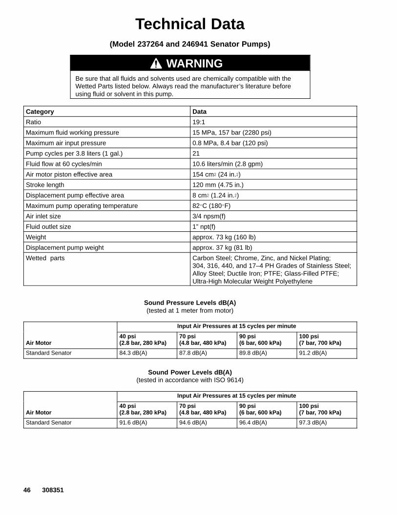
Technical Data(Model 237264 and 246941 Senator Pumps)
WARNINGBe sure that all fluids and solvents used are chemically compatible with theWetted Parts listed below. Always read the manufacturer’s literature beforeusing fluid or solvent in this pump.
Category Data
Ratio 19:1
Maximum fluid working pressure 15 MPa, 157 bar (2280 psi)
Maximum air input pressure 0.8 MPa, 8.4 bar (120 psi)
Pump cycles per 3.8 liters (1 gal.) 21
Fluid flow at 60 cycles/min 10.6 liters/min (2.8 gpm)
Air motor piston effective area 154 cm (24 in.)
Stroke length 120 mm (4.75 in.)
Displacement pump effective area 8 cm (1.24 in.)
Maximum pump operating temperature 82�C (180�F)
Air inlet size 3/4 npsm(f)
Fluid outlet size 1” npt(f)
Weight approx. 73 kg (160 lb)
Displacement pump weight approx. 37 kg (81 lb)
Wetted parts Carbon Steel; Chrome, Zinc, and Nickel Plating; 304, 316, 440, and 17–4 PH Grades of Stainless Steel;Alloy Steel; Ductile Iron; PTFE; Glass-Filled PTFE;Ultra-High Molecular Weight Polyethylene
Sound Pressure Levels dB(A)(tested at 1 meter from motor)
Input Air Pressures at 15 cycles per minute
Air Motor40 psi (2.8 bar, 280 kPa)
70 psi (4.8 bar, 480 kPa)
90 psi (6 bar, 600 kPa)
100 psi (7 bar, 700 kPa)
Standard Senator 84.3 dB(A) 87.8 dB(A) 89.8 dB(A) 91.2 dB(A)
Sound Power Levels dB(A)(tested in accordance with ISO 9614)
Input Air Pressures at 15 cycles per minute
Air Motor40 psi (2.8 bar, 280 kPa)
70 psi (4.8 bar, 480 kPa)
90 psi (6 bar, 600 kPa)
100 psi (7 bar, 700 kPa)
Standard Senator 91.6 dB(A) 94.6 dB(A) 96.4 dB(A) 97.3 dB(A)

308351 47
Technical Data(Model 237264 and 246941 Senator Pumps)
To find Fluid Outlet Pressure (psi/MPa/bar) at a specific fluid flow(lpm/gpm) and operating air pressure (psi/MPa/bar):
1. Locate desired flow along bottom of chart.
2. Follow vertical line up to intersection with selected fluid outletpressure curve (black). Follow left to scale to read fluid outletpressure.
To find Pump Air Consumption (m/min or scfm) at a specific fluidflow (lpm/gpm) and air pressure (psi/MPa/bar):
1. Locate desired flow along bottom of chart.
2. Read vertical line up to intersection with selected air consumptioncurve (dashes). Follow left to scale to read air consumption.
A 0.8 MPa, 8.4 bar (120 psi) air pressure B 0.7 MPa, 7 bar (100 psi) air pressure C 0.5 MPa, 4.9 bar (70 psi) air pressure
Performance Charts
0
1000
2000
3000
0 1 2 3
Fluid Outlet Pressure
21 42 63psi
MPa, barcycles per minute
gpmliters/minute 3.8 7.6 11.4
FL
UID
PR
ES
SU
RE
21, 210
14, 140
7, 70
A
B
C
0
50
100
150
0 1 2 3
Air Consumption
21 42 63scfmm/min
cycles per minute
gpmliters/minute 3.8 7.6 11.4
AIR
CO
NS
UM
PT
ION
AB
C
4.20
2.80
1.40
0
1000
2000
3000
0.0 0.5 1.0 1.5 2.0 2.5
Fluid Outlet Pressure
20 40 50psi
MPa, barcycles per minute
gpmliters/minute 3.8 7.6 9.5
FL
UID
PR
ES
SU
RE
21, 210
14, 140
7, 70
A
C
0
50
100
150
0.0 0.5 1.0 1.5 2.0 2.5
Air Consumptionscfmm/min
cycles per minute
gpmliters/minute
AIR
CO
NS
UM
PT
ION
A
C
4.20
2.80
1.40
Test Fluid: No. 10 Weight Oil
Test Fluid: 4 Million CPS Weldable Rubber Base Sealer
5.71.9
10 30 20 40 50
3.8 7.6 9.55.71.9
10 30

48 308351
Technical Data(Model 198466 and 246938 Viscount II Pumps)
WARNINGBe sure that all fluids and solvents used are chemically compatible with theWetted Parts listed below. Always read the manufacturer’s literature beforeusing fluid or solvent in this pump.
Category Data
Maximum fluid working pressure 40 MPa, 403 bar (5850 psi)
Maximum hydraulic fluid input pressure 10.3 MPa, 103 bar (1500 psi)
Pump cycles per 3.8 liters (1 gal.) 21
Fluid flow at 60 cycles/min 10.6 liters/min (2.8 gpm)
Hydraulic motor piston effective area 31.6 cm (4.9 in.)
Stroke length 120 mm (4.75 in.)
Displacement pump effective area 8 cm (1.24 in.)
Maximum pump operating temperature 82�C (180�F)
Hydraulic fluid inlet size G1/2
Fluid outlet size 1” npt(f)
Weight approx. 80 kg (177 lb)
Displacement pump weight approx. 37 kg (81 lb)
Wetted parts Carbon Steel; Chrome, Zinc, and Nickel Plating; 304, 316, 440, and 17–4 PH Grades of Stainless Steel;Alloy Steel; Ductile Iron; PTFE; Glass-Filled PTFE;Ultra-High Molecular Weight Polyethylene
Sound Pressure Levels dB(A)(measured at 1 meter from unit)
HydraulicMotor
Input Hydraulic Pressures at 25 cycles/min
10 MPa, 100 bar (1450 psi)
Viscount II 88 dB(A)
Sound Power Levels dB(A)(tested in accordance with ISO 3744)
HydraulicMotor
Input Hydraulic Pressures at 25 cycles/min
10 MPa, 100 bar (1450 psi)
Viscount II 103 dB(A)

308351 49
Dimensions and Mounting Hole Layout
04995
A
B
DC
E
88 mm(3.464”)
94.28 mm(3.712”)
11.1 mm(0.437”)DIA (4)
94.28 mm(3.712”)
101.6 mm(4.0”)
50.8 mm(2.0”)
0653
Three M16 x2.0 Holes
F
G
Model 236471 Shown
04508
11.1 mm(0.437 in.)DIA (4)
188.4 mm(7.42 in.)
287.2 mm(11.31 in.)
All Models, except 198466 and 246938
Model 198466 and 246938
Part No. A B C D E F G
236471246942
1376.7 mm(54.20 in.)
583.0 mm(22.95 in.)
793.7 mm(31.25 in.)
728.5 mm(28.68 in.)
257.0 mm(10.12 in.)
1 in. npt(f) 3/4 npsm(f)
237265240945253376
1383.0 mm(54.33 in.)
589.6 mm(23.21 in.)
793.7 mm(31.25 in.)
728.5 mm(28.68 in.)
257.0 mm(10.12 in.)
1 in. npt(f) 3/4 npsm(f)
237261246940
1338.0 mm(52.68 in.)
544.0 mm(21.42 in.)
793.7 mm(31.25 in.)
728.5 mm(28.68 in.)
257.0 mm(10.12 in.)
1 in. npt(f) 3/4 npsm(f)
241901 1494 mm(58.82 in.)
544.0 mm(21.42 in.)
949.0 mm(37.39 in.)
884.0 mm(34.82 in.)
413.0 mm(16.26 in.)
1 in. npt(f) 3/4 npsm(f)
237274 1388.0 mm(54.65 in.)
595.0 mm(23.43 in.)
793.7 mm(31.25 in.)
728.5 mm(28.68 in.)
257.0 mm(10.12 in.)
1 in. npt(f) 3/4 npsm(f)
237264246941
1341.0 mm(52.80 in.)
548.0 mm(21.57 in.)
793.7 mm(31.25 in.)
728.5 mm(28.68 in.)
257.0 mm(10.12 in.)
1 in. npt(f) 3/4 npsm(f)
198466246938
1438.86 mm(56.65 in.)
645.16 mm(25.4 in.)
793.7 mm(31.25 in.)
728.5 mm(28.68 in.)
257.0 mm(10.12 in.)
1 in. npt(f) G 1/2
198475 1339.7 mm(52.74 in.)
546.0 mm(21.5 in.)
793.7 mm(31.25 in.)
728.5 mm(28.68 in.)
257.0 mm(10.12 in.)
1 in. npt(f) G 1/2

50 308351
Graco Standard WarrantyGraco warrants all equipment manufactured by Graco and bearing its name to be free from defects in material and workmanship on thedate of sale to the original purchaser for use. With the exception of any special, extended, or limited warranty published by Graco,Graco will, for a period of twelve months from the date of sale, repair or replace any part of the equipment determined by Graco to bedefective. This warranty applies only when the equipment is installed, operated and maintained in accordance with Graco’s writtenrecommendations.
This warranty does not cover, and Graco shall not be liable for general wear and tear, or any malfunction, damage or wear caused byfaulty installation, misapplication, abrasion, corrosion, inadequate or improper maintenance, negligence, accident, tampering, or sub-stitution of non–Graco component parts. Nor shall Graco be liable for malfunction, damage or wear caused by the incompatibility ofGraco equipment with structures, accessories, equipment or materials not supplied by Graco, or the improper design, manufacture,installation, operation or maintenance of structures, accessories, equipment or materials not supplied by Graco.
This warranty is conditioned upon the prepaid return of the equipment claimed to be defective to an authorized Graco distributor forverification of the claimed defect. If the claimed defect is verified, Graco will repair or replace free of charge any defective parts. Theequipment will be returned to the original purchaser transportation prepaid. If inspection of the equipment does not disclose any defectin material or workmanship, repairs will be made at a reasonable charge, which charges may include the costs of parts, labor, andtransportation.
THIS WARRANTY IS EXCLUSIVE, AND IS IN LIEU OF ANY OTHER WARRANTIES, EXPRESS OR IMPLIED, INCLUDING BUTNOT LIMITED TO WARRANTY OF MERCHANTABILITY OR WARRANTY OF FITNESS FOR A PARTICULAR PURPOSE.
Graco’s sole obligation and buyer’s sole remedy for any breach of warranty shall be as set forth above. The buyer agrees that no otherremedy (including, but not limited to, incidental or consequential damages for lost profits, lost sales, injury to person or property, or anyother incidental or consequential loss) shall be available. Any action for breach of warranty must be brought within two (2) years of thedate of sale.
Graco makes no warranty, and disclaims all implied warranties of merchantability and fitness for a particular purpose in connectionwith accessories, equipment, materials or components sold but not manufactured by Graco. These items sold, but not manufacturedby Graco (such as electric motors, switches, hose, etc.), are subject to the warranty, if any, of their manufacturer. Graco will providepurchaser with reasonable assistance in making any claim for breach of these warranties.
In no event will Graco be liable for indirect, incidental, special or consequential damages resulting from Graco supplying equipmenthereunder, or the furnishing, performance, or use of any products or other goods sold hereto, whether due to a breach of contract,breach of warranty, the negligence of Graco, or otherwise.
FOR GRACO CANADA CUSTOMERSThe parties acknowledge that they have required that the present document, as well as all documents, notices and legal proceedingsentered into, given or instituted pursuant hereto or relating directly or indirectly hereto, be drawn up in English. Les parties reconnais-sent avoir convenu que la rédaction du présente document sera en Anglais, ainsi que tous documents, avis et procédures judiciairesexécutés, donnés ou intentés à la suite de ou en rapport, directement ou indirectement, avec les procedures concernées.
Graco InformationTO PLACE AN ORDER, contact your Graco distributor, or call one of the following numbers
to identify the distributor closest to you:1–800–328–0211 Toll Free
612–623–6921612–378–3505 Fax
All written and visual data contained in this document reflects the latest product information available at the time of publication.Graco reserves the right to make changes at any time without notice.
���������� ��� ������������������ ����������������������
Graco Headquarters: MinneapolisInternational Offices: Belgium, China, Japan, Korea
GRACO INC. AND SUBSIDIARIES � P.O. BOX 1441 � MINNEAPOLIS MN 55440–1441 � USACopyright 1995, Graco Inc. All Graco manufacturing locations are registered to ISO 9001.
www.graco.comRevision L, September 2015