Embed Size (px)
Citation preview
Instructions - Parts
Check-Mate® Pump Packages
For use with non-heated bulk supply of medium to high viscosity sealant and adhesive materials. For professional use only.
See page 3 for model information. See page 39 for maximum fluid working pressure.
Important Safety InstructionsRead all warnings and instructions in this manual before using this equipment. Save these instructions.
ti10420a
P40RCM Model Shown
P42LCS Model Shown
P20LCM ModelShown
r_p20lcs_312376_1e ti28327b
312376PEN
Related Manuals
2 312376P
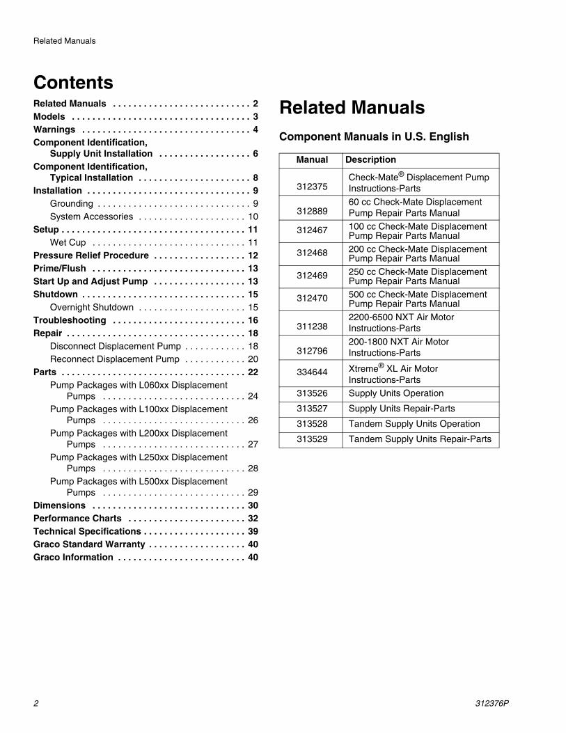
ContentsRelated Manuals . . . . . . . . . . . . . . . . . . . . . . . . . . . 2Models . . . . . . . . . . . . . . . . . . . . . . . . . . . . . . . . . . . 3Warnings . . . . . . . . . . . . . . . . . . . . . . . . . . . . . . . . . 4Component Identification,
Supply Unit Installation . . . . . . . . . . . . . . . . . . 6Component Identification,
Typical Installation . . . . . . . . . . . . . . . . . . . . . . 8Installation . . . . . . . . . . . . . . . . . . . . . . . . . . . . . . . . 9
Grounding . . . . . . . . . . . . . . . . . . . . . . . . . . . . . . 9System Accessories . . . . . . . . . . . . . . . . . . . . . 10
Setup . . . . . . . . . . . . . . . . . . . . . . . . . . . . . . . . . . . . 11Wet Cup . . . . . . . . . . . . . . . . . . . . . . . . . . . . . . 11
Pressure Relief Procedure . . . . . . . . . . . . . . . . . . 12Prime/Flush . . . . . . . . . . . . . . . . . . . . . . . . . . . . . . 13Start Up and Adjust Pump . . . . . . . . . . . . . . . . . . 13Shutdown . . . . . . . . . . . . . . . . . . . . . . . . . . . . . . . . 15
Overnight Shutdown . . . . . . . . . . . . . . . . . . . . . 15Troubleshooting . . . . . . . . . . . . . . . . . . . . . . . . . . 16Repair . . . . . . . . . . . . . . . . . . . . . . . . . . . . . . . . . . . 18
Disconnect Displacement Pump . . . . . . . . . . . . 18Reconnect Displacement Pump . . . . . . . . . . . . 20
Parts . . . . . . . . . . . . . . . . . . . . . . . . . . . . . . . . . . . . 22Pump Packages with L060xx Displacement
Pumps . . . . . . . . . . . . . . . . . . . . . . . . . . . . 24Pump Packages with L100xx Displacement
Pumps . . . . . . . . . . . . . . . . . . . . . . . . . . . . 26Pump Packages with L200xx Displacement
Pumps . . . . . . . . . . . . . . . . . . . . . . . . . . . . 27Pump Packages with L250xx Displacement
Pumps . . . . . . . . . . . . . . . . . . . . . . . . . . . . 28Pump Packages with L500xx Displacement
Pumps . . . . . . . . . . . . . . . . . . . . . . . . . . . . 29Dimensions . . . . . . . . . . . . . . . . . . . . . . . . . . . . . . 30Performance Charts . . . . . . . . . . . . . . . . . . . . . . . 32Technical Specifications . . . . . . . . . . . . . . . . . . . . 39Graco Standard Warranty . . . . . . . . . . . . . . . . . . . 40Graco Information . . . . . . . . . . . . . . . . . . . . . . . . . 40
Related ManualsComponent Manuals in U.S. English
Manual Description
312375Check-Mate® Displacement Pump Instructions-Parts
31288960 cc Check-Mate Displacement Pump Repair Parts Manual
312467 100 cc Check-Mate Displacement Pump Repair Parts Manual
312468 200 cc Check-Mate Displacement Pump Repair Parts Manual
312469 250 cc Check-Mate Displacement Pump Repair Parts Manual
312470 500 cc Check-Mate Displacement Pump Repair Parts Manual
3112382200-6500 NXT Air Motor Instructions-Parts
312796200-1800 NXT Air Motor Instructions-Parts
334644 Xtreme® XL Air Motor Instructions-Parts
313526 Supply Units Operation
313527 Supply Units Repair-Parts
313528 Tandem Supply Units Operation
313529 Tandem Supply Units Repair-Parts
Models
312376P 3
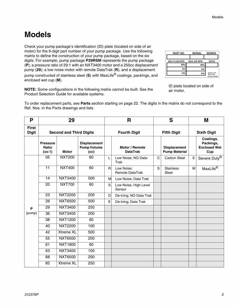
ModelsCheck your pump package’s identification (ID) plate (located on side of air motor) for the 6-digit part number of your pump package. Use the following matrix to define the construction of your pump package, based on the six digits. For example, pump package P29RSM represents the pump package (P); a pressure ratio of 29:1 with an NXT3400 motor and a 250cc displacement pump (29); a low noise motor with remote DataTrak (R); and a displacement
pump constructed of stainless steel (S) with MaxLife® coatings, packings, and enclosed wet cup (M).
NOTE: Some configurations in the following matrix cannot be built. See the Product Selection Guide for available systems.
To order replacement parts, see Parts section starting on page 22. The digits in the matrix do not correspond to the Ref. Nos. in the Parts drawings and lists.
PART NO. SERIAL SERIES
Artwork 293287
MAX AIR WPR RATIOMAX FLUID WPR
MPa
bar
PSI
MPa
bar
PSI GRACO INC. MPLS, MN
ID plate located on side of air motor.
P 29 R S MFirst Digit Second and Third Digits Fourth Digit Fifth Digit Sixth Digit
Pressure Ratio (xx:1) Motor
Displacement Pump Volume
(cc)Motor / Remote
DataTrakDisplacement Pump Material
Coatings, Packings,
Enclosed Wet Cup
P(pump)
05 NXT200 60 L Low Noise; NO Data-Trak
C Carbon Steel S Severe Duty®
11 NXT400 60 R Low Noise; Remote DataTrak
S Stainless Steel
M MaxLife®
14 NXT3400 500 M Low Noise; Data Trak
20 NXT700 60 S Low Noise, High Level Sensor
23 NXT2200 200 D De-Icing; NO Data Trak
26 NXT6500 500 E De-Icing; Data Trak
29 NXT3400 250
36 NXT3400 200
38 NXT1200 60
40 NXT2200 100
42 Xtreme XL 500
55 NXT6500 250
61 NXT1800 60
63 NXT3400 100
68 NXT6500 200
85 Xtreme XL 250
Warnings
4 312376P
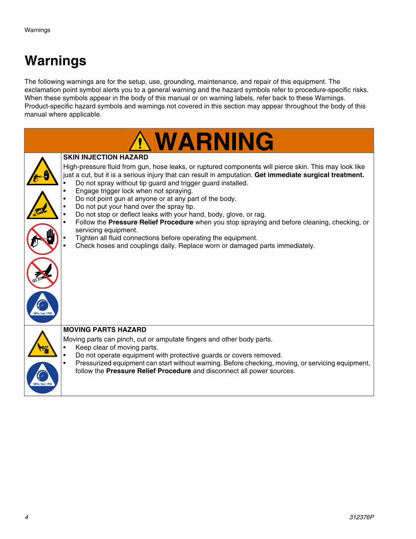
WarningsThe following warnings are for the setup, use, grounding, maintenance, and repair of this equipment. The exclamation point symbol alerts you to a general warning and the hazard symbols refer to procedure-specific risks. When these symbols appear in the body of this manual or on warning labels, refer back to these Warnings. Product-specific hazard symbols and warnings not covered in this section may appear throughout the body of this manual where applicable.
WARNINGSKIN INJECTION HAZARDHigh-pressure fluid from gun, hose leaks, or ruptured components will pierce skin. This may look like just a cut, but it is a serious injury that can result in amputation. Get immediate surgical treatment.• Do not spray without tip guard and trigger guard installed.• Engage trigger lock when not spraying.• Do not point gun at anyone or at any part of the body.• Do not put your hand over the spray tip.• Do not stop or deflect leaks with your hand, body, glove, or rag.• Follow the Pressure Relief Procedure when you stop spraying and before cleaning, checking, or
servicing equipment. • Tighten all fluid connections before operating the equipment.• Check hoses and couplings daily. Replace worn or damaged parts immediately.
MOVING PARTS HAZARDMoving parts can pinch, cut or amputate fingers and other body parts.• Keep clear of moving parts.• Do not operate equipment with protective guards or covers removed.• Pressurized equipment can start without warning. Before checking, moving, or servicing equipment,
follow the Pressure Relief Procedure and disconnect all power sources.
Warnings
312376P 5
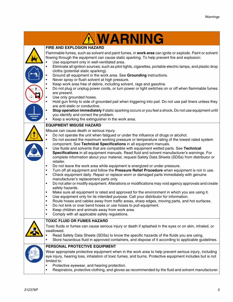
FIRE AND EXPLOSION HAZARDFlammable fumes, such as solvent and paint fumes, in work area can ignite or explode. Paint or solvent flowing through the equipment can cause static sparking. To help prevent fire and explosion:• Use equipment only in well-ventilated area.• Eliminate all ignition sources; such as pilot lights, cigarettes, portable electric lamps, and plastic drop
cloths (potential static sparking). • Ground all equipment in the work area. See Grounding instructions.• Never spray or flush solvent at high pressure.• Keep work area free of debris, including solvent, rags and gasoline.• Do not plug or unplug power cords, or turn power or light switches on or off when flammable fumes
are present.• Use only grounded hoses.• Hold gun firmly to side of grounded pail when triggering into pail. Do not use pail liners unless they
are anti-static or conductive.• Stop operation immediately if static sparking occurs or you feel a shock. Do not use equipment until
you identify and correct the problem.• Keep a working fire extinguisher in the work area.
EQUIPMENT MISUSE HAZARDMisuse can cause death or serious injury.• Do not operate the unit when fatigued or under the influence of drugs or alcohol.• Do not exceed the maximum working pressure or temperature rating of the lowest rated system
component. See Technical Specifications in all equipment manuals.• Use fluids and solvents that are compatible with equipment wetted parts. See Technical
Specifications in all equipment manuals. Read fluid and solvent manufacturer’s warnings. For complete information about your material, request Safety Data Sheets (SDSs) from distributor or retailer.
• Do not leave the work area while equipment is energized or under pressure.• Turn off all equipment and follow the Pressure Relief Procedure when equipment is not in use.• Check equipment daily. Repair or replace worn or damaged parts immediately with genuine
manufacturer’s replacement parts only.• Do not alter or modify equipment. Alterations or modifications may void agency approvals and create
safety hazards.• Make sure all equipment is rated and approved for the environment in which you are using it.• Use equipment only for its intended purpose. Call your distributor for information.• Route hoses and cables away from traffic areas, sharp edges, moving parts, and hot surfaces.• Do not kink or over bend hoses or use hoses to pull equipment.• Keep children and animals away from work area.• Comply with all applicable safety regulations.
TOXIC FLUID OR FUMES HAZARDToxic fluids or fumes can cause serious injury or death if splashed in the eyes or on skin, inhaled, or swallowed.• Read Safety Data Sheets (SDSs) to know the specific hazards of the fluids you are using.• Store hazardous fluid in approved containers, and dispose of it according to applicable guidelines.
PERSONAL PROTECTIVE EQUIPMENTWear appropriate protective equipment when in the work area to help prevent serious injury, including eye injury, hearing loss, inhalation of toxic fumes, and burns. Protective equipment includes but is not limited to:• Protective eyewear, and hearing protection. • Respirators, protective clothing, and gloves as recommended by the fluid and solvent manufacturer.
WARNING
Component Identification, Supply Unit Installation
6 312376P
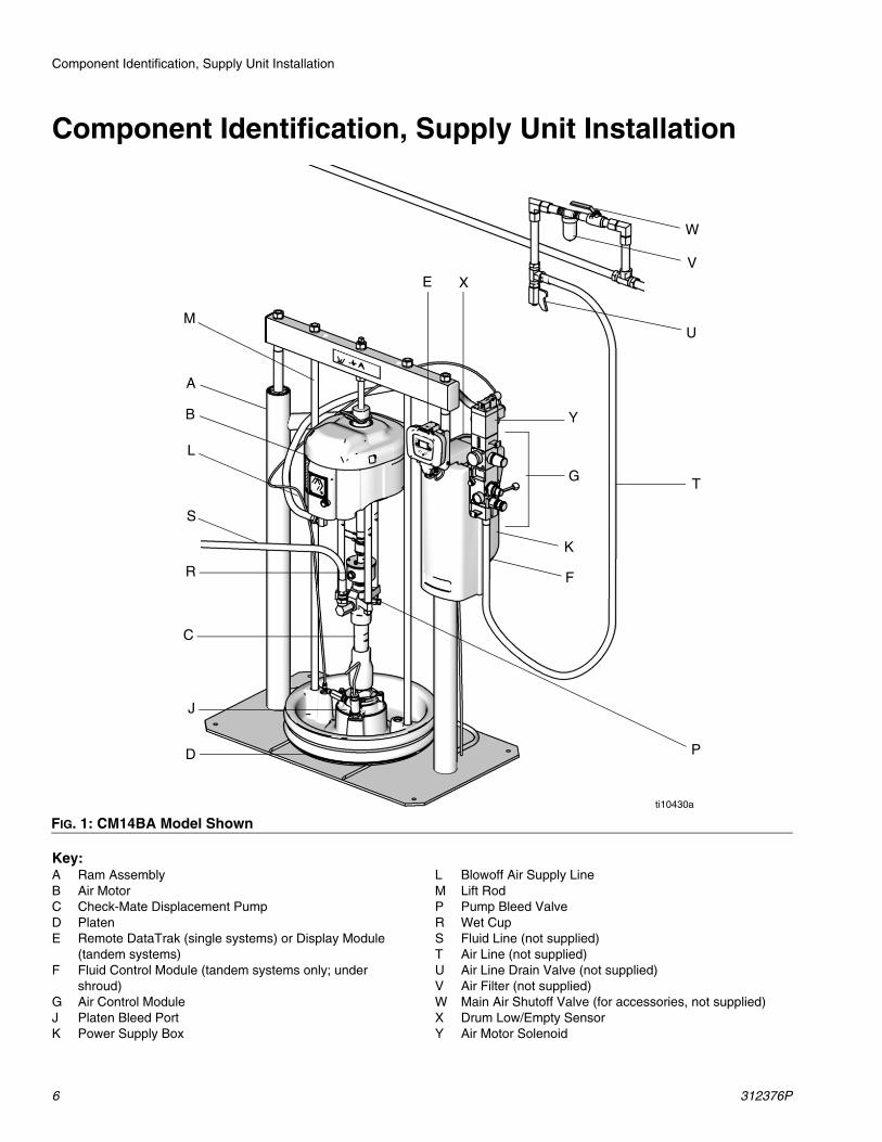
Component Identification, Supply Unit Installation
Key:A Ram AssemblyB Air MotorC Check-Mate Displacement PumpD PlatenE Remote DataTrak (single systems) or Display Module
(tandem systems)F Fluid Control Module (tandem systems only; under
shroud)G Air Control ModuleJ Platen Bleed PortK Power Supply Box
L Blowoff Air Supply LineM Lift RodP Pump Bleed ValveR Wet CupS Fluid Line (not supplied)T Air Line (not supplied)U Air Line Drain Valve (not supplied)V Air Filter (not supplied)W Main Air Shutoff Valve (for accessories, not supplied)X Drum Low/Empty SensorY Air Motor Solenoid
FIG. 1: CM14BA Model Shownti10430a
W
V
U
T
L
G
F
K
E
A
M
R
J
D P
C
S
B
X
Y
Component Identification, Supply Unit Installation
312376P 7
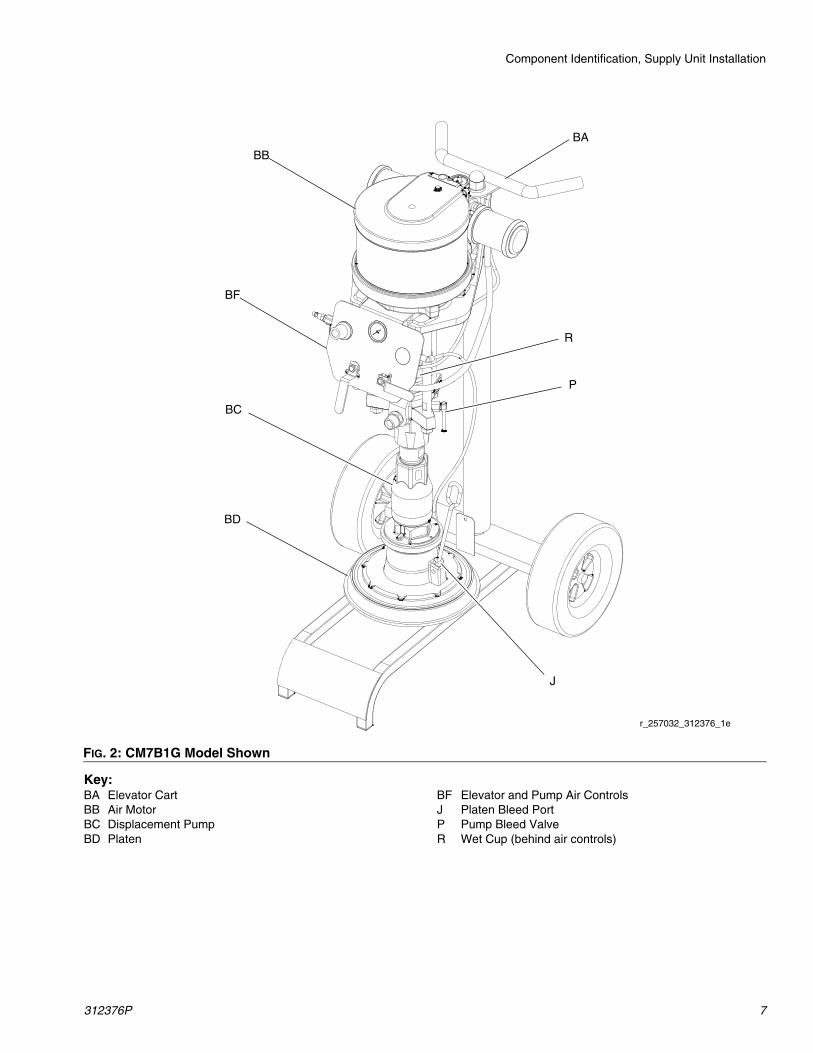
Key:BA Elevator CartBB Air MotorBC Displacement PumpBD Platen
BF Elevator and Pump Air ControlsJ Platen Bleed PortP Pump Bleed ValveR Wet Cup (behind air controls)
FIG. 2: CM7B1G Model Shown
BF
BB
BA
BC
BD
R
r_257032_312376_1e
P
J
Component Identification, Typical Installation
8 312376P
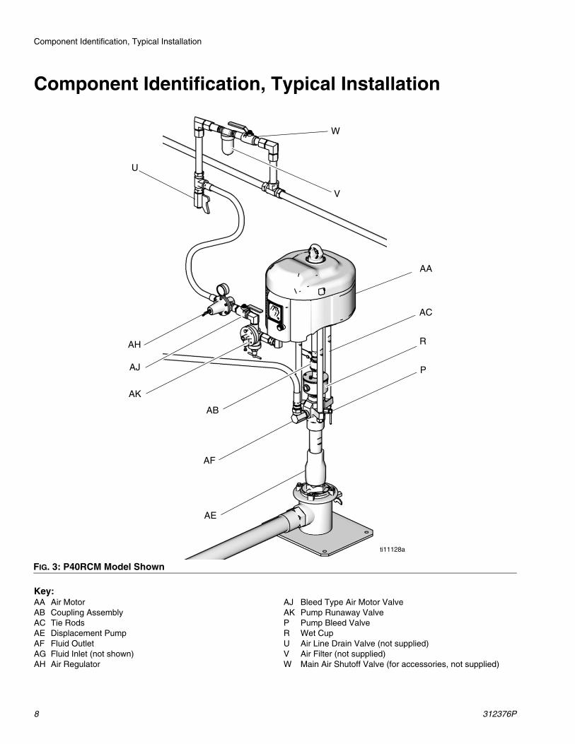
Component Identification, Typical Installation
Key:AA Air MotorAB Coupling AssemblyAC Tie RodsAE Displacement PumpAF Fluid OutletAG Fluid Inlet (not shown)AH Air Regulator
AJ Bleed Type Air Motor ValveAK Pump Runaway ValveP Pump Bleed ValveR Wet CupU Air Line Drain Valve (not supplied)V Air Filter (not supplied)W Main Air Shutoff Valve (for accessories, not supplied)
FIG. 3: P40RCM Model Shown
AA
AB
AC
R
AE
AF
ti11128a
W
V
U
P
AH
AJ
AK
Installation
312376P 9
Installation
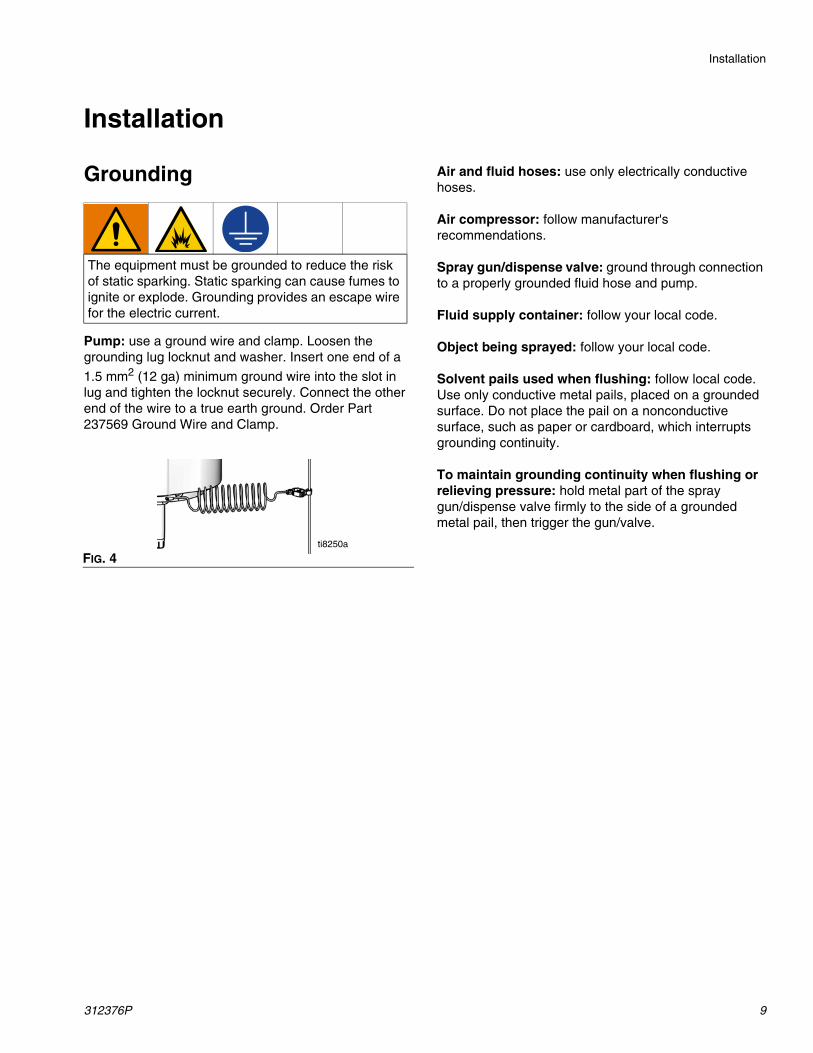
Grounding
Pump: use a ground wire and clamp. Loosen the grounding lug locknut and washer. Insert one end of a
1.5 mm2 (12 ga) minimum ground wire into the slot in lug and tighten the locknut securely. Connect the other end of the wire to a true earth ground. Order Part 237569 Ground Wire and Clamp.
Air and fluid hoses: use only electrically conductive hoses.
Air compressor: follow manufacturer's recommendations.
Spray gun/dispense valve: ground through connection to a properly grounded fluid hose and pump.
Fluid supply container: follow your local code.
Object being sprayed: follow your local code.
Solvent pails used when flushing: follow local code. Use only conductive metal pails, placed on a grounded surface. Do not place the pail on a nonconductive surface, such as paper or cardboard, which interrupts grounding continuity.
To maintain grounding continuity when flushing or relieving pressure: hold metal part of the spray gun/dispense valve firmly to the side of a grounded metal pail, then trigger the gun/valve.
The equipment must be grounded to reduce the risk of static sparking. Static sparking can cause fumes to ignite or explode. Grounding provides an escape wire for the electric current.
FIG. 4ti8250a
Installation
10 312376P
System Accessories
NOTE: If using Check-Mate pump with Graco Supply Systems, refer to Supply Systems Operation manual for system accessory installation instructions. For use with all other systems, use this section for accessory installation instructions.
Be sure all air lines (T) and fluid lines (S) are properly sized and pressure-rated for your system. Use only electrically conductive hoses. Fluid hoses must have spring guards on both ends.
Mounting Accessories
Mount the pump package to suit the type of installation planned. Pump dimensions are shown on page 30. Refer to Check-Mate Displacement Pump manual 312375 for mounting hole layout.
Air Line Accessories
Install the following accessories as listed. Refer to FIG. 1 to see air line accessories represented in a typical supply unit installation.
• Main air shutoff valve (W) isolates the air line accessories for servicing. Locate upstream from all other air line accessories.
• Air line filter (V) removes harmful dirt and moisture from the compressed air supply. Also, install a drain valve at the bottom of each air line drop, to drain off moisture.
• Air regulator (G and AH) controls pump speed and outlet pressure by adjusting the air pressure to the pump. Locate the regulator close to the pump, but upstream from the bleed-type master air valve.
• Bleed type air motor valve (AJ) is required in your system to shut off the air supply to the pump (see WARNING). When closed, the valve will bleed off all air in the pump. Be sure the valve is easily accessi-ble from the pump.
• Pump runaway valve (AK) senses when the pump is running too fast and automatically shuts off the air to the motor. A pump which runs too fast can be seriously damaged. Locate in the position shown.
• Pump bleed valve (P) is required in your system to relieve fluid pressure in hose and gun (see WARN-ING).
Fluid Line Accessories
Install the following accessories as listed. Refer to FIG. 2 to see fluid line accessories represented in a typical supply unit installation.
• Install a fluid shutoff valve at each gun/valve drop, to isolate the gun/valve and fluid accessories for servicing.
• Install a fluid drain valve near the pump fluid outlet, and at each gun/valve station. The drain valves are required in your system to relieve fluid pressure in the displacement pump, hose and gun/valve. Drain valves at the gun/valve stations may be mounted in the base of a fluid regulator, using an adapter.
• Fluid regulator controls fluid pressure to the gun/valve, and dampens pressure surges.
• Gun or dispense valve dispenses the fluid.
• Gun/valve swivel allows freer gun/valve movement.
A main air shut off valve (W), a bleed type air motor valve (AJ), and a pump bleed valve (P) are required. These accessories help reduce the risk of serious injury, including fluid injection and splashing of fluid in the eyes or on the skin, and injury from moving parts if you are adjusting or repairing the pump.
The main air shutoff valve (W) shuts off the air to the pump and ram. The bleed type air motor valve (AJ) relieves air trapped between this valve and the pump after the air is shut off. Trapped air can cause the pump to cycle unexpectedly. Locate the valve close to the pump.
The pump bleed valve (P) assists in relieving fluid pressure in the displacement pump, hose, and gun/valve. Triggering the gun/valve to relieve pressure may not be sufficient.
Setup
312376P 11
Setup
Wet Cup
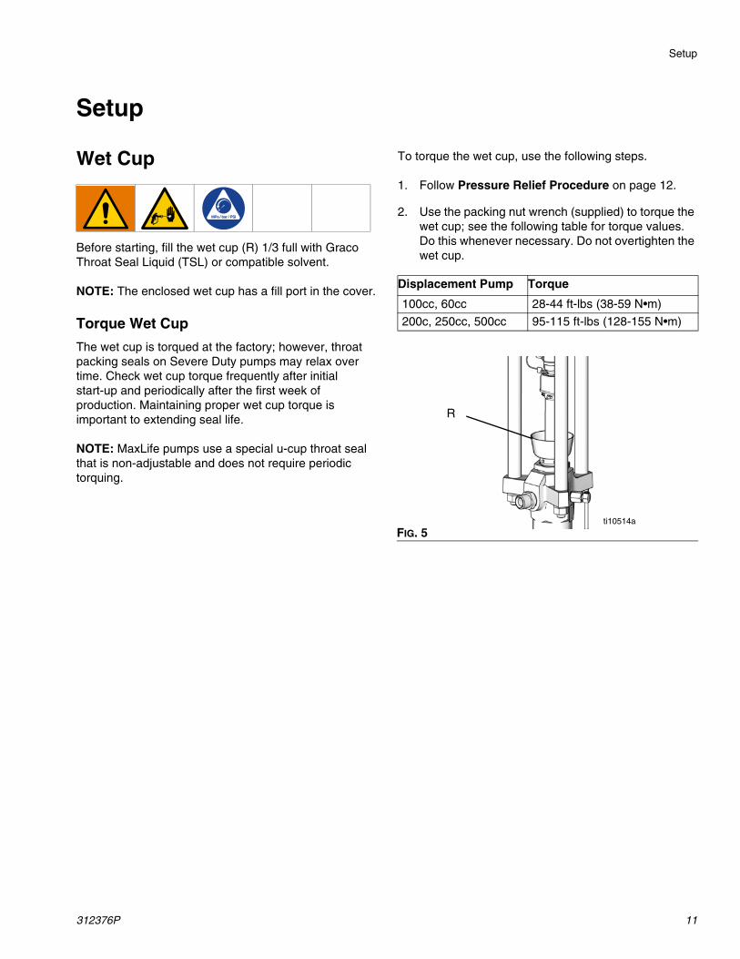
Before starting, fill the wet cup (R) 1/3 full with Graco Throat Seal Liquid (TSL) or compatible solvent.
NOTE: The enclosed wet cup has a fill port in the cover.
Torque Wet Cup
The wet cup is torqued at the factory; however, throat packing seals on Severe Duty pumps may relax over time. Check wet cup torque frequently after initial start-up and periodically after the first week of production. Maintaining proper wet cup torque is important to extending seal life.
NOTE: MaxLife pumps use a special u-cup throat seal that is non-adjustable and does not require periodic torquing.
To torque the wet cup, use the following steps.
1. Follow Pressure Relief Procedure on page 12.
2. Use the packing nut wrench (supplied) to torque the wet cup; see the following table for torque values. Do this whenever necessary. Do not overtighten the wet cup.
Displacement Pump Torque
100cc, 60cc 28-44 ft-lbs (38-59 N•m)
200c, 250cc, 500cc 95-115 ft-lbs (128-155 N•m)
FIG. 5
R
ti10514a
Pressure Relief Procedure
12 312376P
Pressure Relief ProcedureFollow the Pressure Relief Procedure whenever you see this symbol.
1. Engage the gun/valve trigger.
2. For D200s, D200, D60 and S20 Air Controls: See FIG. 6.
a. Close the air motor slider valve and the main air slider valve.
b. Set the ram director valve to DOWN. The ram will slowly drop.
c. Jog the director valve up and down to bleed air
from ram cylinders.
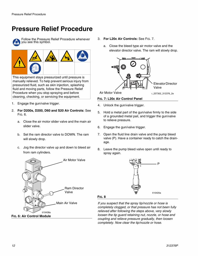
3. For L20c Air Controls: See FIG. 7.
a. Close the bleed type air motor valve and the elevator director valve. The ram will slowly drop.
4. Unlock the gun/valve trigger.
5. Hold a metal part of the gun/valve firmly to the side of a grounded metal pail, and trigger the gun/valve to relieve pressure.
6. Engage the gun/valve trigger.
7. Open the fluid line drain valve and the pump bleed valve (P). Have a container ready to catch the drain-age.
8. Leave the pump bleed valve open until ready to spray again.
If you suspect that the spray tip/nozzle or hose is completely clogged, or that pressure has not been fully relieved after following the steps above, very slowly loosen the tip guard retaining nut, nozzle, or hose end coupling and relieve pressure gradually, then loosen completely. Now clear the tip/nozzle or hose.
This equipment stays pressurized until pressure is manually relieved. To help prevent serious injury from pressurized fluid, such as skin injection, splashing fluid and moving parts, follow the Pressure Relief Procedure when you stop spraying and before cleaning, checking, or servicing the equipment.
FIG. 6: Air Control Module
Main Air Valve
Ram DirectorValve
ti10438a
Air Motor Valve
FIG. 7: L20c Air Control Panel
FIG. 8
Elevator Director Valve
Air Motor Valve r_257302_312376_2e
ti10420a
P
Prime/Flush
312376P 13
Prime/Flush
NOTE: The pump is tested with lightweight oil, which is left in to protect the pump parts. If the fluid you are using may be contaminated by the oil, flush it out with a compatible solvent before using the pump.
Flush with a fluid that is compatible with the fluid you are pumping and with the wetted parts in your system. Check with your fluid manufacturer or supplier for recommended flushing fluids and flushing frequency. Always flush the pump before fluid dries on the displacement rod.
1. Follow Pressure Relief Procedure on page 12.
2. Remove the spray tip/nozzle from the gun/valve.
3. Hold a metal part of the gun/valve firmly to the side of a grounded metal pail.
4. Start the pump. Always use the lowest possible fluid pressure when flushing.
5. Trigger the gun/valve.
6. Flush the system until clear solvent flows from the gun/valve.
7. Relieve the pressure.
Start Up and Adjust Pump
1. Supply fluid to the pump, per the requirements of your system.
2. Be sure the pump air regulator is closed.
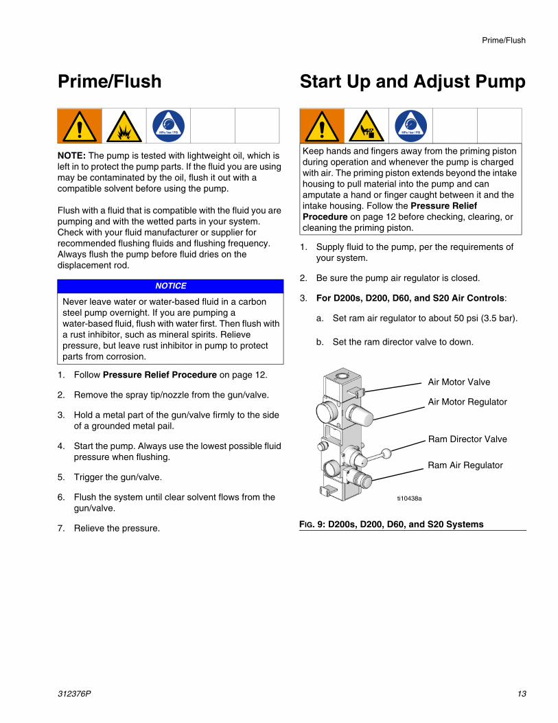
3. For D200s, D200, D60, and S20 Air Controls:
a. Set ram air regulator to about 50 psi (3.5 bar).
b. Set the ram director valve to down.
NOTICE
Never leave water or water-based fluid in a carbon steel pump overnight. If you are pumping a water-based fluid, flush with water first. Then flush with a rust inhibitor, such as mineral spirits. Relieve pressure, but leave rust inhibitor in pump to protect parts from corrosion.
Keep hands and fingers away from the priming piston during operation and whenever the pump is charged with air. The priming piston extends beyond the intake housing to pull material into the pump and can amputate a hand or finger caught between it and the intake housing. Follow the Pressure Relief Procedure on page 12 before checking, clearing, or cleaning the priming piston.
FIG. 9: D200s, D200, D60, and S20 Systems
Ram Air Regulator
Ram Director Valve
ti10438a
Air Motor Regulator
Air Motor Valve
Start Up and Adjust Pump
14 312376P
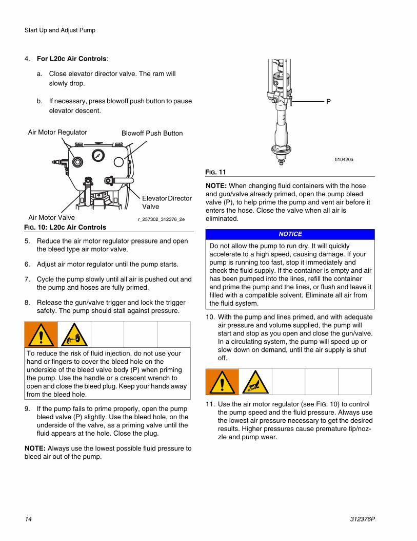
4. For L20c Air Controls:
a. Close elevator director valve. The ram will slowly drop.
b. If necessary, press blowoff push button to pause elevator descent.
5. Reduce the air motor regulator pressure and open the bleed type air motor valve.
6. Adjust air motor regulator until the pump starts.
7. Cycle the pump slowly until all air is pushed out and the pump and hoses are fully primed.
8. Release the gun/valve trigger and lock the trigger safety. The pump should stall against pressure.
9. If the pump fails to prime properly, open the pump bleed valve (P) slightly. Use the bleed hole, on the underside of the valve, as a priming valve until the fluid appears at the hole. Close the plug.
NOTE: Always use the lowest possible fluid pressure to bleed air out of the pump.
NOTE: When changing fluid containers with the hose and gun/valve already primed, open the pump bleed valve (P), to help prime the pump and vent air before it enters the hose. Close the valve when all air is eliminated.
10. With the pump and lines primed, and with adequate air pressure and volume supplied, the pump will start and stop as you open and close the gun/valve. In a circulating system, the pump will speed up or slow down on demand, until the air supply is shut off.
11. Use the air motor regulator (see FIG. 10) to control the pump speed and the fluid pressure. Always use the lowest air pressure necessary to get the desired results. Higher pressures cause premature tip/noz-zle and pump wear.
FIG. 10: L20c Air Controls
To reduce the risk of fluid injection, do not use your hand or fingers to cover the bleed hole on the underside of the bleed valve body (P) when priming the pump. Use the handle or a crescent wrench to open and close the bleed plug. Keep your hands away from the bleed hole.
Air Motor Regulator
Elevator Director Valve
Air Motor Valve r_257302_312376_2e
Blowoff Push Button
FIG. 11
NOTICE
Do not allow the pump to run dry. It will quickly accelerate to a high speed, causing damage. If your pump is running too fast, stop it immediately and check the fluid supply. If the container is empty and air has been pumped into the lines, refill the container and prime the pump and the lines, or flush and leave it filled with a compatible solvent. Eliminate all air from the fluid system.
ti10420a
P
Shutdown
312376P 15
Shutdown
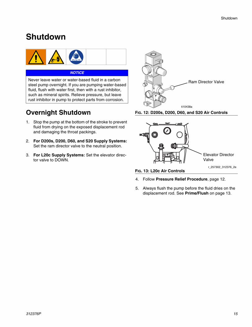
Overnight Shutdown1. Stop the pump at the bottom of the stroke to prevent
fluid from drying on the exposed displacement rod and damaging the throat packings.
2. For D200s, D200, D60, and S20 Supply Systems: Set the ram director valve to the neutral position.
3. For L20c Supply Systems: Set the elevator direc-tor valve to DOWN.
4. Follow Pressure Relief Procedure, page 12.
5. Always flush the pump before the fluid dries on the displacement rod. See Prime/Flush on page 13.
NOTICE
Never leave water or water-based fluid in a carbon steel pump overnight. If you are pumping water-based fluid, flush with water first, then with a rust inhibitor, such as mineral spirits. Relieve pressure, but leave rust inhibitor in pump to protect parts from corrosion.
FIG. 12: D200s, D200, D60, and S20 Air Controls
FIG. 13: L20c Air Controls
Ram Director Valve
ti10438a
Elevator DirectorValve
r_257302_312376_2e
Troubleshooting
16 312376P
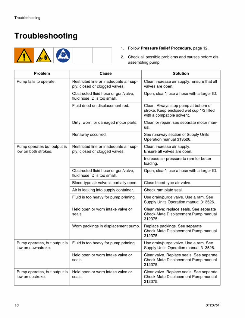
Troubleshooting1. Follow Pressure Relief Procedure, page 12.
2. Check all possible problems and causes before dis-assembling pump.
Problem Cause Solution
Pump fails to operate. Restricted line or inadequate air sup-ply; closed or clogged valves.
Clear; increase air supply. Ensure that all valves are open.
Obstructed fluid hose or gun/valve; fluid hose ID is too small.
Open, clear*; use a hose with a larger ID.
Fluid dried on displacement rod. Clean. Always stop pump at bottom of stroke. Keep enclosed wet cup 1/3 filled with a compatible solvent.
Dirty, worn, or damaged motor parts. Clean or repair; see separate motor man-ual.
Runaway occurred. See runaway section of Supply Units Operation manual 313526.
Pump operates but output is low on both strokes.
Restricted line or inadequate air sup-ply; closed or clogged valves.
Clear; increase air supply.Ensure all valves are open.
Increase air pressure to ram for better loading.
Obstructed fluid hose or gun/valve; fluid hose ID is too small.
Open, clear*; use a hose with a larger ID.
Bleed-type air valve is partially open. Close bleed-type air valve.
Air is leaking into supply container. Check ram plate seal.
Fluid is too heavy for pump priming. Use drain/purge valve. Use a ram. See Supply Units Operation manual 313526.
Held open or worn intake valve or seals.
Clear valve; replace seals. See separate Check-Mate Displacement Pump manual 312375.
Worn packings in displacement pump. Replace packings. See separate Check-Mate Displacement Pump manual 312375.
Pump operates, but output is low on downstroke.
Fluid is too heavy for pump priming. Use drain/purge valve. Use a ram. See Supply Units Operation manual 313526.
Held open or worn intake valve or seals.
Clear valve. Replace seals. See separate Check-Mate Displacement Pump manual 312375.
Pump operates, but output is low on upstroke.
Held open or worn intake valve or seals.
Clear valve. Replace seals. See separate Check-Mate Displacement Pump manual 312375.
Troubleshooting
312376P 17
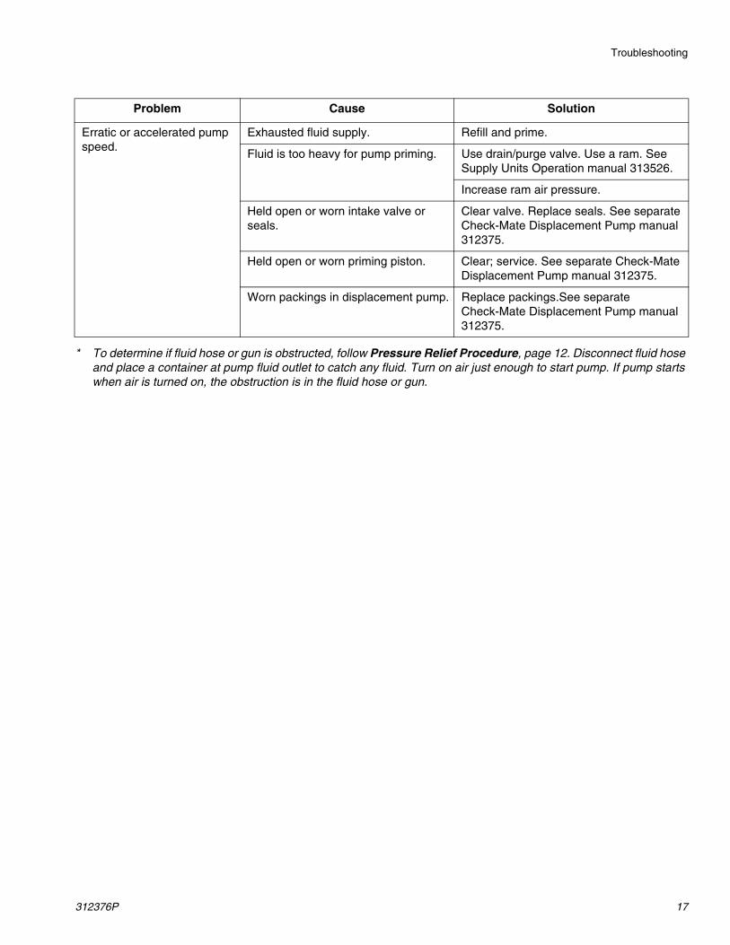
* To determine if fluid hose or gun is obstructed, follow Pressure Relief Procedure, page 12. Disconnect fluid hose and place a container at pump fluid outlet to catch any fluid. Turn on air just enough to start pump. If pump starts when air is turned on, the obstruction is in the fluid hose or gun.
Erratic or accelerated pump speed.
Exhausted fluid supply. Refill and prime.
Fluid is too heavy for pump priming. Use drain/purge valve. Use a ram. See Supply Units Operation manual 313526.
Increase ram air pressure.
Held open or worn intake valve or seals.
Clear valve. Replace seals. See separate Check-Mate Displacement Pump manual 312375.
Held open or worn priming piston. Clear; service. See separate Check-Mate Displacement Pump manual 312375.
Worn packings in displacement pump. Replace packings.See separate Check-Mate Displacement Pump manual 312375.
Problem Cause Solution
Repair
18 312376P
Repair
Required Tools
• Torque wrench• Hammer• Packing nut wrench (supplied with displacement
pump)• Set of socket wrenches• Set of adjustable wrenches
• Loctite® 2760™ or equivalent• Brass rod (pumps with 500cc displacement pumps
only)• Torque wrench with claw foot (pumps with 60cc and
500cc displacement pumps only)
Disconnect Displacement Pump
1. Flush pump; see Prime/Flush, page 13. Stop pump at bottom of its stroke. Follow Pressure Relief Pro-cedure, page 12.
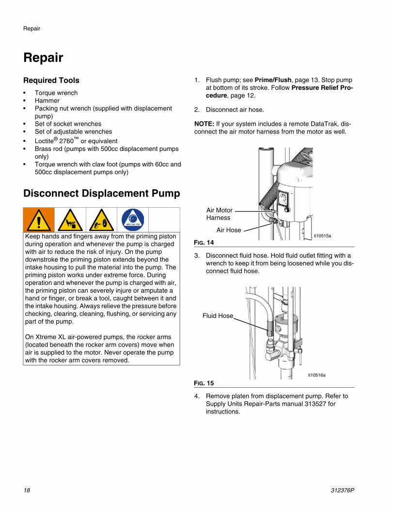
2. Disconnect air hose.
NOTE: If your system includes a remote DataTrak, dis-connect the air motor harness from the motor as well.
3. Disconnect fluid hose. Hold fluid outlet fitting with a wrench to keep it from being loosened while you dis-connect fluid hose.
4. Remove platen from displacement pump. Refer to Supply Units Repair-Parts manual 313527 for instructions.
Keep hands and fingers away from the priming piston during operation and whenever the pump is charged with air to reduce the risk of injury. On the pump downstroke the priming piston extends beyond the intake housing to pull the material into the pump. The priming piston works under extreme force. During operation and whenever the pump is charged with air, the priming piston can severely injure or amputate a hand or finger, or break a tool, caught between it and the intake housing. Always relieve the pressure before checking, clearing, cleaning, flushing, or servicing any part of the pump.
On Xtreme XL air-powered pumps, the rocker arms (located beneath the rocker arm covers) move when air is supplied to the motor. Never operate the pump with the rocker arm covers removed.
FIG. 14
FIG. 15
Air Hose
Air Motor
ti10515a
Harness
Fluid Hose
ti10516a
Repair
312376P 19
5. If the air motor does not require servicing, leave it attached to its mounting. However, if the air motor does need to be removed, refer to the Supply Units Repair-Parts manual 313527 for instructions.
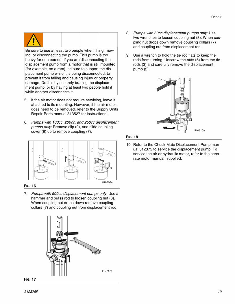
6. Pumps with 100cc, 200cc, and 250cc displacement pumps only: Remove clip (9), and slide coupling cover (8) up to remove coupling (7).
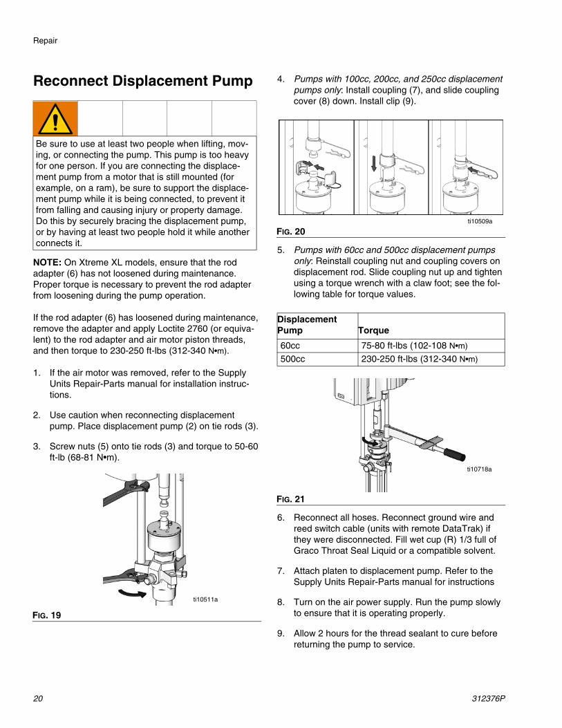
7. Pumps with 500cc displacement pumps only: Use a hammer and brass rod to loosen coupling nut (8). When coupling nut drops down remove coupling collars (7) and coupling nut from displacement rod.
8. Pumps with 60cc displacement pumps only: Use two wrenches to loosen coupling nut (8). When cou-pling nut drops down remove coupling collars (7) and coupling nut from displacement rod.
9. Use a wrench to hold the tie rod flats to keep the rods from turning. Unscrew the nuts (5) from the tie rods (3) and carefully remove the displacement pump (2).
10. Refer to the Check-Mate Displacement Pump man-ual 312375 to service the displacement pump. To service the air or hydraulic motor, refer to the sepa-rate motor manual, supplied.
Be sure to use at least two people when lifting, mov-ing, or disconnecting the pump. This pump is too heavy for one person. If you are disconnecting the displacement pump from a motor that is still mounted (for example, on a ram), be sure to support the dis-placement pump while it is being disconnected, to prevent it from falling and causing injury or property damage. Do this by securely bracing the displace-ment pump, or by having at least two people hold it while another disconnects it.
FIG. 16
FIG. 17
ti10508a
ti10717a
FIG. 18
ti10510a
Repair
20 312376P
Reconnect Displacement Pump
NOTE: On Xtreme XL models, ensure that the rod adapter (6) has not loosened during maintenance. Proper torque is necessary to prevent the rod adapter from loosening during the pump operation.
If the rod adapter (6) has loosened during maintenance, remove the adapter and apply Loctite 2760 (or equiva-lent) to the rod adapter and air motor piston threads, and then torque to 230-250 ft-lbs (312-340 N•m).
1. If the air motor was removed, refer to the Supply Units Repair-Parts manual for installation instruc-tions.
2. Use caution when reconnecting displacement pump. Place displacement pump (2) on tie rods (3).
3. Screw nuts (5) onto tie rods (3) and torque to 50-60 ft-lb (68-81 N•m).
4. Pumps with 100cc, 200cc, and 250cc displacement pumps only: Install coupling (7), and slide coupling cover (8) down. Install clip (9).
5. Pumps with 60cc and 500cc displacement pumps only: Reinstall coupling nut and coupling covers on displacement rod. Slide coupling nut up and tighten using a torque wrench with a claw foot; see the fol-lowing table for torque values.
6. Reconnect all hoses. Reconnect ground wire and reed switch cable (units with remote DataTrak) if they were disconnected. Fill wet cup (R) 1/3 full of Graco Throat Seal Liquid or a compatible solvent.
7. Attach platen to displacement pump. Refer to the Supply Units Repair-Parts manual for instructions
8. Turn on the air power supply. Run the pump slowly to ensure that it is operating properly.
9. Allow 2 hours for the thread sealant to cure before returning the pump to service.
Be sure to use at least two people when lifting, mov-ing, or connecting the pump. This pump is too heavy for one person. If you are connecting the displace-ment pump from a motor that is still mounted (for example, on a ram), be sure to support the displace-ment pump while it is being connected, to prevent it from falling and causing injury or property damage. Do this by securely bracing the displacement pump, or by having at least two people hold it while another connects it.
FIG. 19
ti10511a
FIG. 20
Displacement Pump Torque
60cc 75-80 ft-lbs (102-108 N•m)
500cc 230-250 ft-lbs (312-340 N•m)
FIG. 21
ti10509a
ti10718a
Repair
312376P 21
Parts
22 312376P
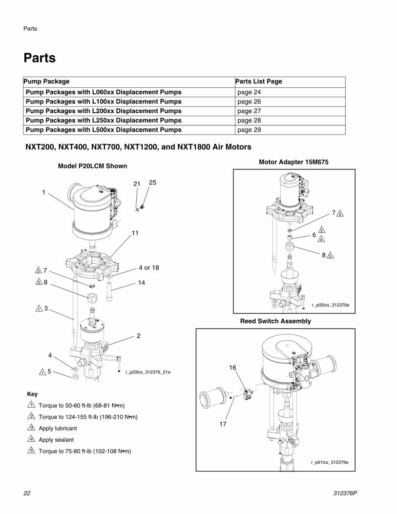
Parts
Pump Package Parts List Page
Pump Packages with L060xx Displacement Pumps page 24
Pump Packages with L100xx Displacement Pumps page 26
Pump Packages with L200xx Displacement Pumps page 27
Pump Packages with L250xx Displacement Pumps page 28
Pump Packages with L500xx Displacement Pumps page 29
Key
Torque to 50-60 ft-lb (68-81 N•m)
Torque to 124-155 ft-lb (196-210 N•m)
Apply lubricant
Apply sealant
Torque to 75-80 ft-lb (102-108 N•m)
1
2
3
4
5
Motor Adapter 15M675Model P20LCM Shown
Reed Switch Assembly
r_p61lcs_312376e
16
17
r_p05lcs_312376e
r_p20lcs_312376_21e
4
1
11
7
8
4 or 18
2
8
1 3
51
62
4
5
5
7 3
3
14
NXT200, NXT400, NXT700, NXT1200, and NXT1800 Air Motors
21 25
Parts
312376P 23
1
2
5
4
3
9
6
7
8
2
4
1
ti10421a
1
20
1
1
2
5
4
3
6
8
2 4
5
1
7 3
10
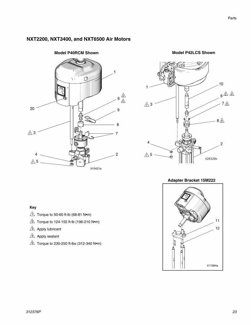
Model P42LCS ShownModel P40RCM Shown
Adapter Bracket 15M222
11
12
ti11084a
NXT2200, NXT3400, and NXT6500 Air Motors
Key
Torque to 50-60 ft-lb (68-81 N•m)
Torque to 124-155 ft-lb (196-210 N•m)
Apply lubricant
Apply sealant
Torque to 230-250 ft-lbs (312-340 N•m)
1
2
3
4
5
Parts
24 312376P
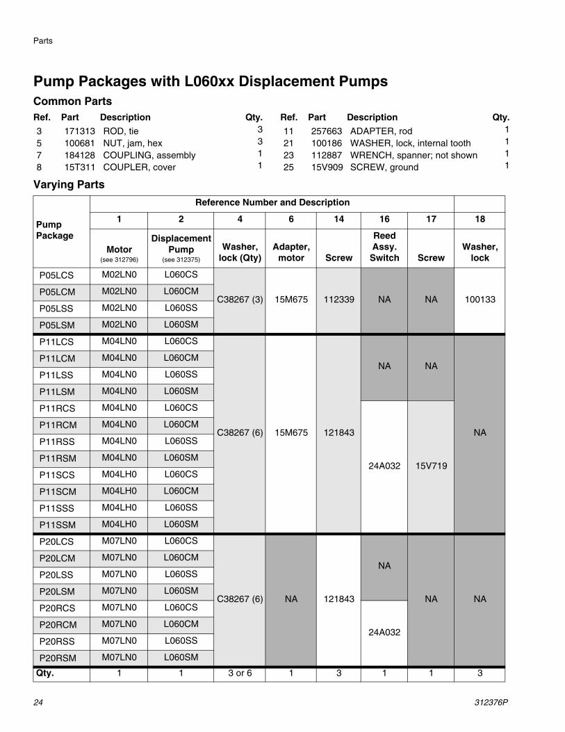
Pump Packages with L060xx Displacement PumpsCommon Parts
Varying Parts
Ref. Part Description Qty. Ref. Part Description Qty.
3 171313 ROD, tie 3 11 257663 ADAPTER, rod 1
5 100681 NUT, jam, hex 3 21 100186 WASHER, lock, internal tooth 1
7 184128 COUPLING, assembly 1 23 112887 WRENCH, spanner; not shown 1
8 15T311 COUPLER, cover 1 25 15V909 SCREW, ground 1
Pump Package
Reference Number and Description
1 2 4 6 14 16 17 18
Motor(see 312796)
Displacement Pump
(see 312375)
Washer, lock (Qty)
Adapter, motor Screw
Reed Assy. Switch Screw
Washer, lock
P05LCS M02LN0 L060CS
C38267 (3) 15M675 112339 NA NA 100133P05LCM M02LN0 L060CM
P05LSS M02LN0 L060SS
P05LSM M02LN0 L060SM
P11LCS M04LN0 L060CS
C38267 (6) 15M675 121843
NA NA
NA
P11LCM M04LN0 L060CM
P11LSS M04LN0 L060SS
P11LSM M04LN0 L060SM
P11RCS M04LN0 L060CS
24A032 15V719
P11RCM M04LN0 L060CM
P11RSS M04LN0 L060SS
P11RSM M04LN0 L060SM
P11SCS M04LH0 L060CS
P11SCM M04LH0 L060CM
P11SSS M04LH0 L060SS
P11SSM M04LH0 L060SM
P20LCS M07LN0 L060CS
C38267 (6) NA 121843
NA
NA NA
P20LCM M07LN0 L060CM
P20LSS M07LN0 L060SS
P20LSM M07LN0 L060SM
P20RCS M07LN0 L060CS
24A032P20RCM M07LN0 L060CM
P20RSS M07LN0 L060SS
P20RSM M07LN0 L060SM
Qty. 1 1 3 or 6 1 3 1 1 3
Parts
312376P 25
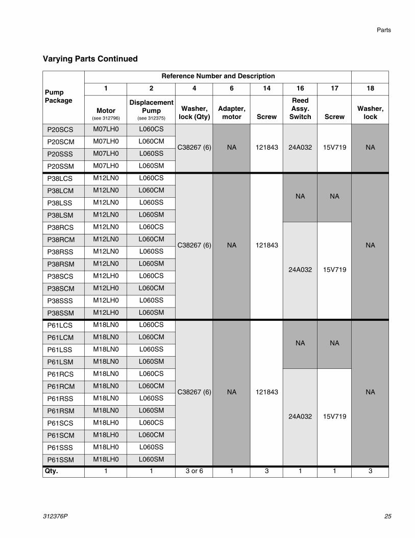
Varying Parts Continued
Pump Package
Reference Number and Description
1 2 4 6 14 16 17 18
Motor(see 312796)
Displacement Pump
(see 312375)
Washer, lock (Qty)
Adapter, motor Screw
Reed Assy. Switch Screw
Washer, lock
P20SCS M07LH0 L060CS
C38267 (6) NA 121843 24A032 15V719 NAP20SCM M07LH0 L060CM
P20SSS M07LH0 L060SS
P20SSM M07LH0 L060SM
P38LCS M12LN0 L060CS
C38267 (6) NA 121843
NA NA
NA
P38LCM M12LN0 L060CM
P38LSS M12LN0 L060SS
P38LSM M12LN0 L060SM
P38RCS M12LN0 L060CS
24A032 15V719
P38RCM M12LN0 L060CM
P38RSS M12LN0 L060SS
P38RSM M12LN0 L060SM
P38SCS M12LH0 L060CS
P38SCM M12LH0 L060CM
P38SSS M12LH0 L060SS
P38SSM M12LH0 L060SM
P61LCS M18LN0 L060CS
C38267 (6) NA 121843
NA NA
NA
P61LCM M18LN0 L060CM
P61LSS M18LN0 L060SS
P61LSM M18LN0 L060SM
P61RCS M18LN0 L060CS
24A032 15V719
P61RCM M18LN0 L060CM
P61RSS M18LN0 L060SS
P61RSM M18LN0 L060SM
P61SCS M18LH0 L060CS
P61SCM M18LH0 L060CM
P61SSS M18LH0 L060SS
P61SSM M18LH0 L060SM
Qty. 1 1 3 or 6 1 3 1 1 3
Parts
26 312376P
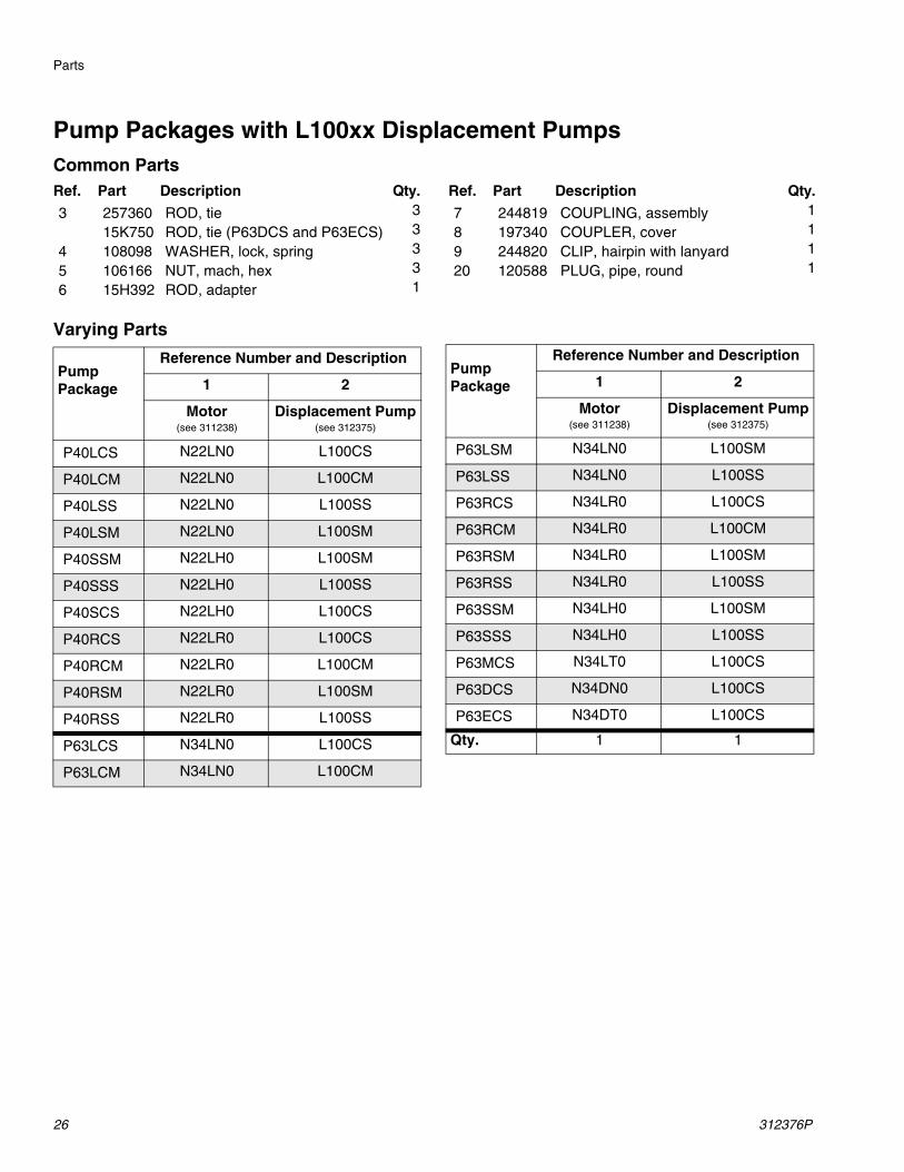
Pump Packages with L100xx Displacement PumpsCommon Parts
Varying Parts
Ref. Part Description Qty. Ref. Part Description Qty.
3 257360 ROD, tie 3 7 244819 COUPLING, assembly 1
15K750 ROD, tie (P63DCS and P63ECS) 3 8 197340 COUPLER, cover 1
4 108098 WASHER, lock, spring 3 9 244820 CLIP, hairpin with lanyard 1
5 106166 NUT, mach, hex 3 20 120588 PLUG, pipe, round 1
6 15H392 ROD, adapter 1
Pump Package
Reference Number and Description
1 2
Motor(see 311238)
Displacement Pump(see 312375)
P40LCS N22LN0 L100CS
P40LCM N22LN0 L100CM
P40LSS N22LN0 L100SS
P40LSM N22LN0 L100SM
P40SSM N22LH0 L100SM
P40SSS N22LH0 L100SS
P40SCS N22LH0 L100CS
P40RCS N22LR0 L100CS
P40RCM N22LR0 L100CM
P40RSM N22LR0 L100SM
P40RSS N22LR0 L100SS
P63LCS N34LN0 L100CS
P63LCM N34LN0 L100CM
P63LSM N34LN0 L100SM
P63LSS N34LN0 L100SS
P63RCS N34LR0 L100CS
P63RCM N34LR0 L100CM
P63RSM N34LR0 L100SM
P63RSS N34LR0 L100SS
P63SSM N34LH0 L100SM
P63SSS N34LH0 L100SS
P63MCS N34LT0 L100CS
P63DCS N34DN0 L100CS
P63ECS N34DT0 L100CS
Qty. 1 1
Pump Package
Reference Number and Description
1 2
Motor(see 311238)
Displacement Pump(see 312375)
Parts
312376P 27
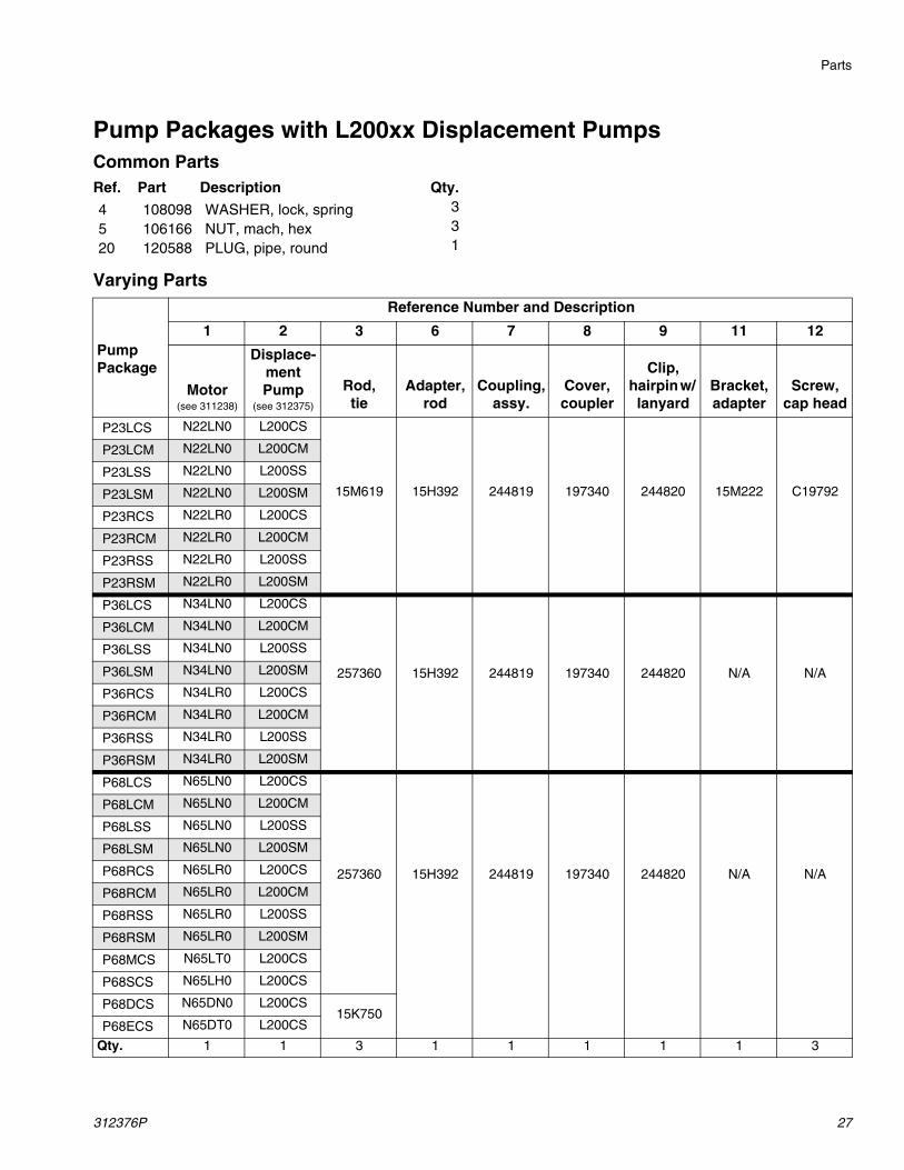
Pump Packages with L200xx Displacement PumpsCommon Parts
Varying Parts
Ref. Part Description Qty.
4 108098 WASHER, lock, spring 3
5 106166 NUT, mach, hex 3
20 120588 PLUG, pipe, round 1
Pump Package
Reference Number and Description
1 2 3 6 7 8 9 11 12
Motor(see 311238)
Displace-ment Pump
(see 312375)
Rod, tie
Adapter, rod
Coupling, assy.
Cover, coupler
Clip, hairpin w/ lanyard
Bracket, adapter
Screw, cap head
P23LCS N22LN0 L200CS
15M619 15H392 244819 197340 244820 15M222 C19792
P23LCM N22LN0 L200CM
P23LSS N22LN0 L200SS
P23LSM N22LN0 L200SM
P23RCS N22LR0 L200CS
P23RCM N22LR0 L200CM
P23RSS N22LR0 L200SS
P23RSM N22LR0 L200SM
P36LCS N34LN0 L200CS
257360 15H392 244819 197340 244820 N/A N/A
P36LCM N34LN0 L200CM
P36LSS N34LN0 L200SS
P36LSM N34LN0 L200SM
P36RCS N34LR0 L200CS
P36RCM N34LR0 L200CM
P36RSS N34LR0 L200SS
P36RSM N34LR0 L200SM
P68LCS N65LN0 L200CS
257360 15H392 244819 197340 244820 N/A N/A
P68LCM N65LN0 L200CM
P68LSS N65LN0 L200SS
P68LSM N65LN0 L200SM
P68RCS N65LR0 L200CS
P68RCM N65LR0 L200CM
P68RSS N65LR0 L200SS
P68RSM N65LR0 L200SM
P68MCS N65LT0 L200CS
P68SCS N65LH0 L200CS
P68DCS N65DN0 L200CS15K750
P68ECS N65DT0 L200CS
Qty. 1 1 3 1 1 1 1 1 3
Parts
28 312376P
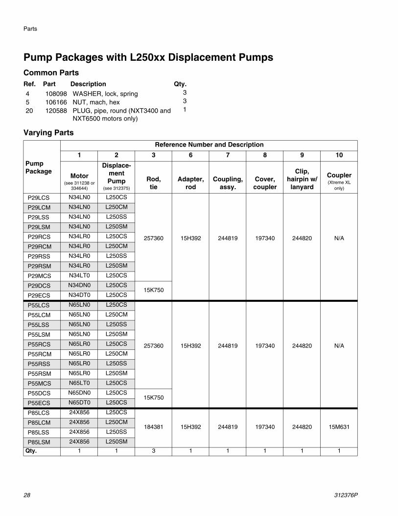
Pump Packages with L250xx Displacement PumpsCommon Parts
Varying Parts
Ref. Part Description Qty.
4 108098 WASHER, lock, spring 3
5 106166 NUT, mach, hex 3
20 120588 PLUG, pipe, round (NXT3400 and NXT6500 motors only)
1
Pump Package
Reference Number and Description
1 2 3 6 7 8 9 10
Motor(see 311238 or
334644)
Displace-ment Pump
(see 312375)
Rod,tie
Adapter, rod
Coupling, assy.
Cover, coupler
Clip, hairpin w/
lanyard
Coupler (Xtreme XL
only)
P29LCS N34LN0 L250CS
257360 15H392 244819 197340 244820 N/A
P29LCM N34LN0 L250CM
P29LSS N34LN0 L250SS
P29LSM N34LN0 L250SM
P29RCS N34LR0 L250CS
P29RCM N34LR0 L250CM
P29RSS N34LR0 L250SS
P29RSM N34LR0 L250SM
P29MCS N34LT0 L250CS
P29DCS N34DN0 L250CS15K750
P29ECS N34DT0 L250CS
P55LCS N65LN0 L250CS
257360 15H392 244819 197340 244820 N/A
P55LCM N65LN0 L250CM
P55LSS N65LN0 L250SS
P55LSM N65LN0 L250SM
P55RCS N65LR0 L250CS
P55RCM N65LR0 L250CM
P55RSS N65LR0 L250SS
P55RSM N65LR0 L250SM
P55MCS N65LT0 L250CS
P55DCS N65DN0 L250CS15K750
P55ECS N65DT0 L250CS
P85LCS 24X856 L250CS
184381 15H392 244819 197340 244820 15M631P85LCM 24X856 L250CM
P85LSS 24X856 L250SS
P85LSM 24X856 L250SM
Qty. 1 1 3 1 1 1 1 1
Parts
312376P 29
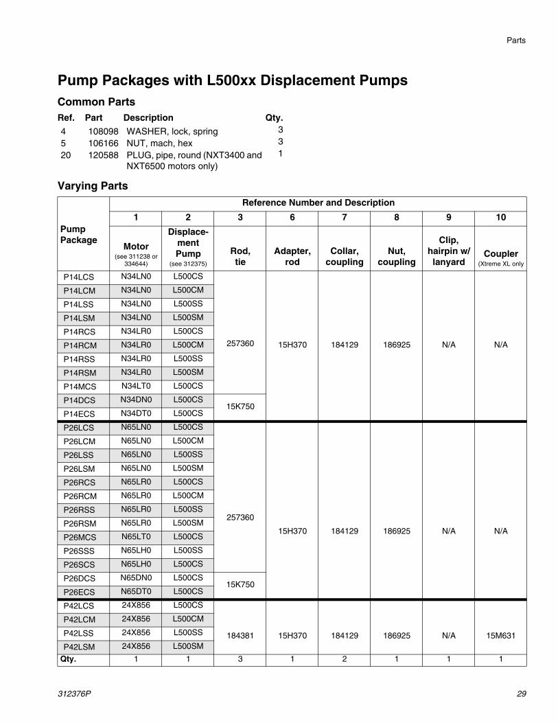
Pump Packages with L500xx Displacement PumpsCommon Parts
Varying Parts
Ref. Part Description Qty.
4 108098 WASHER, lock, spring 3
5 106166 NUT, mach, hex 3
20 120588 PLUG, pipe, round (NXT3400 and NXT6500 motors only)
1
Pump Package
Reference Number and Description
1 2 3 6 7 8 9 10
Motor(see 311238 or
334644)
Displace-ment Pump
(see 312375)
Rod,tie
Adapter, rod
Collar, coupling
Nut, coupling
Clip, hairpin w/ lanyard
Coupler (Xtreme XL only
P14LCS N34LN0 L500CS
257360 15H370 184129 186925 N/A N/A
P14LCM N34LN0 L500CM
P14LSS N34LN0 L500SS
P14LSM N34LN0 L500SM
P14RCS N34LR0 L500CS
P14RCM N34LR0 L500CM
P14RSS N34LR0 L500SS
P14RSM N34LR0 L500SM
P14MCS N34LT0 L500CS
P14DCS N34DN0 L500CS15K750
P14ECS N34DT0 L500CS
P26LCS N65LN0 L500CS
257360
15H370 184129 186925 N/A N/A
P26LCM N65LN0 L500CM
P26LSS N65LN0 L500SS
P26LSM N65LN0 L500SM
P26RCS N65LR0 L500CS
P26RCM N65LR0 L500CM
P26RSS N65LR0 L500SS
P26RSM N65LR0 L500SM
P26MCS N65LT0 L500CS
P26SSS N65LH0 L500SS
P26SCS N65LH0 L500CS
P26DCS N65DN0 L500CS15K750
P26ECS N65DT0 L500CS
P42LCS 24X856 L500CS
184381 15H370 184129 186925 N/A 15M631
P42LCM 24X856 L500CM
P42LSS 24X856 L500SS
P42LSM 24X856 L500SM
Qty. 1 1 3 1 2 1 1 1
Dimensions
30 312376P
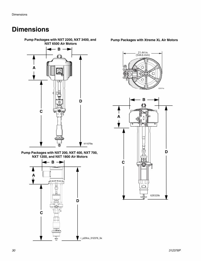
Dimensions
21.44 in.(544.6 mm)
Pump Packages with Xtreme XL Air Motors
A
C
D
ti11079a
Pump Packages with NXT 2200, NXT 3400, and NXT 6500 Air Motors
A
C
B
D
Pump Packages with NXT 200, NXT 400, NXT 700, NXT 1200, and NXT 1800 Air Motors
B
A
D
C
r_p20lcs_312376_3e
B
Dimensions
312376P 31
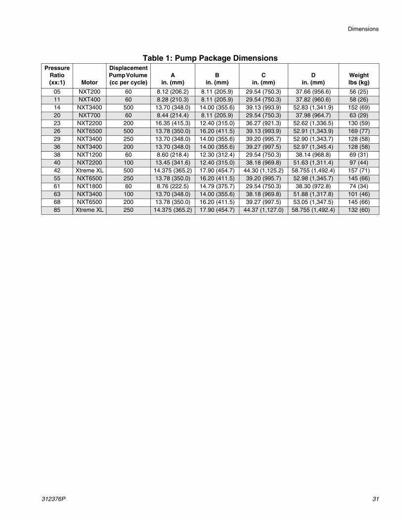
Table 1: Pump Package DimensionsPressure
Ratio (xx:1) Motor
Displacement Pump Volume (cc per cycle)
Ain. (mm)
Bin. (mm)
Cin. (mm)
Din. (mm)
Weightlbs (kg)
05 NXT200 60 8.12 (206.2) 8.11 (205.9) 29.54 (750.3) 37.66 (956.6) 56 (25)11 NXT400 60 8.28 (210.3) 8.11 (205.9) 29.54 (750.3) 37.82 (960.6) 58 (26)14 NXT3400 500 13.70 (348.0) 14.00 (355.6) 39.13 (993.9) 52.83 (1,341.9) 152 (69)20 NXT700 60 8.44 (214.4) 8.11 (205.9) 29.54 (750.3) 37.98 (964.7) 63 (29)23 NXT2200 200 16.35 (415.3) 12.40 (315.0) 36.27 (921.3) 52.62 (1,336.5) 130 (59)26 NXT6500 500 13.78 (350.0) 16.20 (411.5) 39.13 (993.9) 52.91 (1,343.9) 169 (77)29 NXT3400 250 13.70 (348.0) 14.00 (355.6) 39.20 (995.7) 52.90 (1,343.7) 128 (58)36 NXT3400 200 13.70 (348.0) 14.00 (355.6) 39.27 (997.5) 52.97 (1,345.4) 128 (58)38 NXT1200 60 8.60 (218.4) 12.30 (312.4) 29.54 (750.3) 38.14 (968.8) 69 (31)40 NXT2200 100 13.45 (341.6) 12.40 (315.0) 38.18 (969.8) 51.63 (1,311.4) 97 (44)42 Xtreme XL 500 14.375 (365.2) 17.90 (454.7) 44.30 (1,125.2) 58.755 (1,492.4) 157 (71)55 NXT6500 250 13.78 (350.0) 16.20 (411.5) 39.20 (995.7) 52.98 (1,345.7) 145 (66)61 NXT1800 60 8.76 (222.5) 14.79 (375.7) 29.54 (750.3) 38.30 (972.8) 74 (34)63 NXT3400 100 13.70 (348.0) 14.00 (355.6) 38.18 (969.8) 51.88 (1,317.8) 101 (46)68 NXT6500 200 13.78 (350.0) 16.20 (411.5) 39.27 (997.5) 53.05 (1,347.5) 145 (66)85 Xtreme XL 250 14.375 (365.2) 17.90 (454.7) 44.37 (1,127.0) 58.755 (1,492.4) 132 (60)
Performance Charts
32 312376P
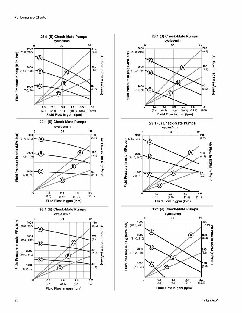
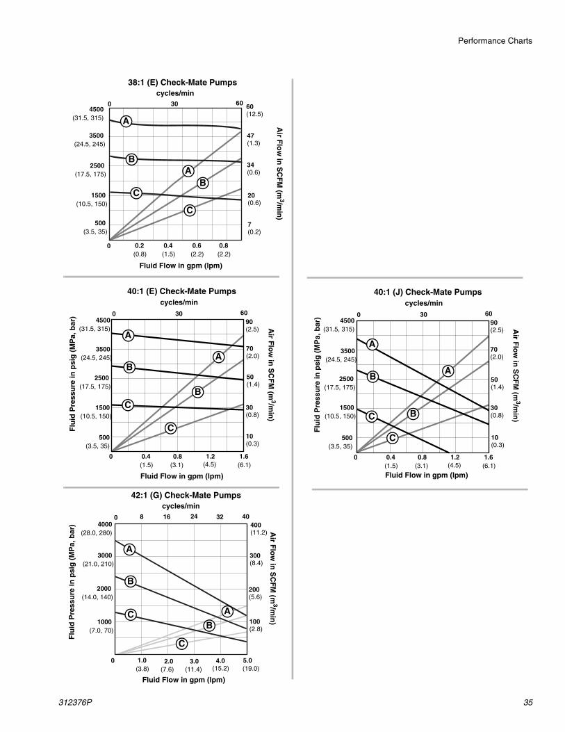
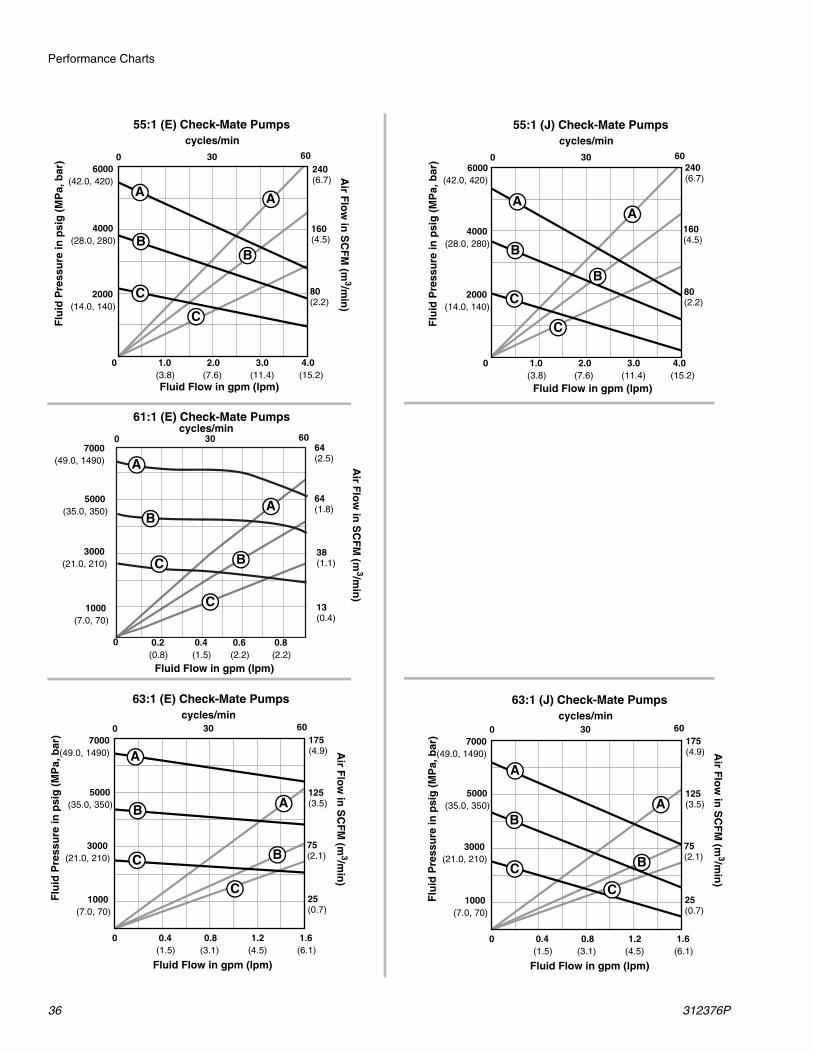
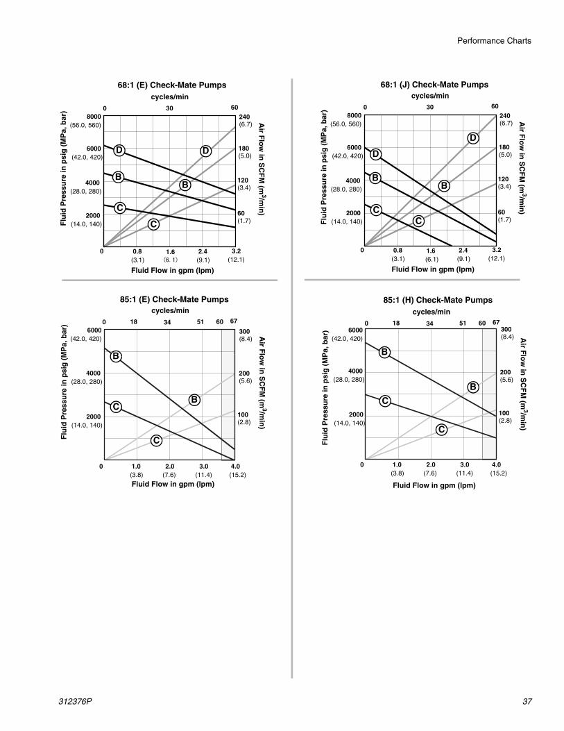
Performance Charts
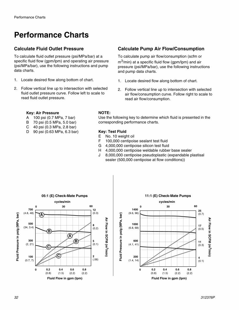
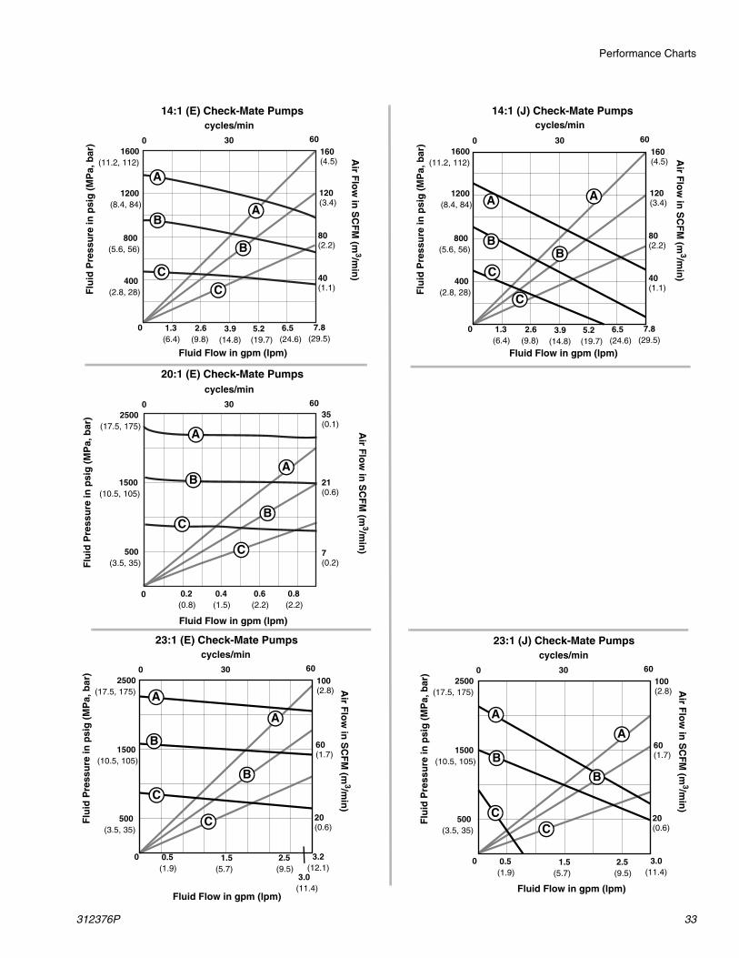
Calculate Fluid Outlet Pressure
To calculate fluid outlet pressure (psi/MPa/bar) at a specific fluid flow (gpm/lpm) and operating air pressure (psi/MPa/bar), use the following instructions and pump data charts.
1. Locate desired flow along bottom of chart.
2. Follow vertical line up to intersection with selected fluid outlet pressure curve. Follow left to scale to read fluid outlet pressure.
Calculate Pump Air Flow/Consumption
To calculate pump air flow/consumption (scfm or
m3/min) at a specific fluid flow (gpm/lpm) and air pressure (psi/MPa/bar), use the following instructions and pump data charts.
1. Locate desired flow along bottom of chart.
2. Follow vertical line up to intersection with selected air flow/consumption curve. Follow right to scale to read air flow/consumption.
Key: Air PressureA 100 psi (0.7 MPa, 7 bar)B 70 psi (0.5 MPa, 5.0 bar)C 40 psi (0.3 MPa, 2.8 bar)D 90 psi (0.63 MPa, 6.3 bar)
NOTE:Use the following key to determine which fluid is presented in the corresponding performance charts.
Key: Test FluidE No. 10 weight oil F 100,000 centipoise sealant test fluidG 4,000,000 centipoise silicon test fluidH 4,000,000 centipoise weldable rubber base sealerJ 8,000,000 centipoise pseudoplastic (expandable plastisal
sealer (500,000 centipoise at flow conditions))
05:1 (E) Check-Mate Pumps 11:1 (E) Check-Mate Pumps
Flu
id P
ress
ure
in p
sig
(M
Pa,
bar
)
Fluid Flow in gpm (lpm)
0
cycles/min
30 600
Air F
low
in S
CF
M (m
3/min
)
0.2(0.8)
0.4(1.5)
0.6(2.2)
100 (0.7, 7)
300 (2, 21)
500 (34, 3.4)
700 (4.8, 48) A
B
C
AB
C
cycles/min
30 600
Flu
id P
ress
ure
in p
sig
(M
Pa,
bar
)
Air F
low
in S
CF
M (m
3/min
)
Fluid Flow in gpm (lpm)
00.8(2.2)
200 (1.4, 14)
600 (4.1, 41)
1000 (6.8, 68)
1400 (9.6, 96)
0.2(0.8)
0.4(1.5)
0.6(2.2)
0.8(2.2)
2(.06)
5(0.1)
8(0.2)
12(0.3)
4(0.1)
11(0.3)
17(0.5)
25(0.7)
Performance Charts
312376P 33
23:1 (E) Check-Mate Pumps
Flu
id P
ress
ure
in p
sig
(M
Pa,
bar
)
Fluid Flow in gpm (lpm)
Air F
low
in S
CF
M (m
3/min
)
500
1500
2500
0 1.50.5(1.9) (5.7)
3.2(12.1)
(17.5, 175)
(10.5, 105)
(3.5, 35)
100(2.8)
60(1.7)
20(0.6)
A
A
B
B
C
C
cycles/min
3.0(11.4)
2.5(9.5)
30 600
23:1 (J) Check-Mate Pumps
Flu
id P
ress
ure
in p
sig
(M
Pa,
bar
)
Fluid Flow in gpm (lpm)
Air F
low
in S
CF
M (m
3/min
)
500
1500
2500
0 1.50.5(1.9) (5.7)
3.0(11.4)
(17.5, 175)
(10.5, 105)
(3.5, 35)
100(2.8)
60(1.7)
20(0.6)
A
A
B
B
CC
cycles/min
2.5(9.5)
30 600
14:1 (E) Check-Mate Pumps
Flu
id P
ress
ure
in p
sig
(M
Pa,
bar
)
Fluid Flow in gpm (lpm)
800
1200
1600
400
0 2.6 3.91.3(6.4) (9.8) (14.8)
7.8(29.5)
(11.2, 112)
(8.4, 84)
(5.6, 56)
(2.8, 28)
160(4.5)
120(3.4)
80(2.2)
40(1.1)
A
A
B
B
C
C
cycles/min
6.5(24.6)
5.2(19.7)
30 600
14:1 (J) Check-Mate Pumps
Flu
id P
ress
ure
in p
sig
(M
Pa,
bar
)
Fluid Flow in gpm (lpm)
Air F
low
in S
CF
M (m
3/min
)
800
1200
1600
400
0 2.6 3.91.3(6.4) (9.8) (14.8)
7.8(29.5)
(11.2, 112)
(8.4, 84)
(5.6, 56)
(2.8, 28)
160(4.5)
120(3.4)
80(2.2)
40(1.1)
AA
BB
C
C
cycles/min
6.5(24.6)
5.2(19.7)
30 600
Air F
low
in S
CF
M (m
3/min
)20:1 (E) Check-Mate Pumps
cycles/min
30 600
Flu
id P
ress
ure
in p
sig
(M
Pa,
bar
)
Fluid Flow in gpm (lpm)
0
Air F
low
in S
CF
M (m
3/min
)
0.2(0.8)
0.4(1.5)
0.6(2.2)
500 (3.5, 35)
1500 (10.5, 105)
2500 (17.5, 175)
A
B
C
A
B
C
0.8(2.2)
7(0.2)
21(0.6)
35(0.1)
Performance Charts
34 312376P
36:1 (J) Check-Mate Pumps
Flu
id P
ress
ure
in p
sig
(M
Pa,
bar
)
Fluid Flow in gpm (lpm)
Air F
low
in S
CF
M (m
3/min
)
2000
3000
4000
1000
0 0.8(3.1)
3.2(12.1)
(28.0, 280)
(21.0, 210)
(14.0, 140)
(7.0, 70)
400(11.2)
300(8.4)
200(5.6)
100(2.8)
AA
B
B
CC
cycles/min
1.6(6.1)
2.4(9.1)
30 600
36:1 (E) Check-Mate Pumps
Flu
id P
ress
ure
in p
sig
(M
Pa,
bar
)
Fluid Flow in gpm (lpm)
Air F
low
in S
CF
M (m
3/min
)
2000
3000
4000
1000
0 1.60.8(3.1) (6.1)
3.2(12.1)
(28.0, 280)
(21.0, 210)
(14.0, 140)
(7.0, 70)
160(4.5)
120(3.4)
80(2.2)
40(1.1)
A
A
B
BC
C
cycles/min
2.4(9.1)
30 600
26:1 (E) Check-Mate Pumps
Flu
id P
ress
ure
in p
sig
(M
Pa,
bar
)
Air F
low
in S
CF
M (m
3/min
)
Fluid Flow in gpm (lpm)
1000
2000
3000(21.0, 210)
(14.0, 140)
(7.0, 70)
240(6.7)
160(4.5)
80(2.2)
A
C
A
B
B
C
cycles/min
0 2.6 3.91.3(6.4) (9.8) (14.8)
7.8(29.5)
6.5(24.6)
5.2(19.7)
30 600
26:1 (J) Check-Mate Pumps
Flu
id P
ress
ure
in p
sig
(M
Pa,
bar
)
Fluid Flow in gpm (lpm)
1000
2000
3000(21.0, 210)
(14.0, 140)
(7.0, 70)
240(6.7)
160(4.5)
80(2.2)
A
C
A
B
B
C
cycles/min
0 2.6 3.91.3(6.4) (9.8) (14.8)
7.8(29.5)
6.5(24.6)
5.2(19.7)
30 600
29:1 (J) Check-Mate PumpsF
luid
Pre
ssu
re in
psi
g (
MP
a, b
ar)
Air F
low
in S
CF
M (m
3/min
)
Fluid Flow in gpm (lpm)
1000
2000
3000(21.0, 210)
(14.0, 140)
(7.0, 70)
240(6.7)
160(4.5)
80(2.2)
A
C
A
B
B
C
cycles/min
0 2.01.0(3.8) (7.6)
4.0(15.2)
3.0(11.4)
30 600
29:1 (E) Check-Mate Pumps
Flu
id P
ress
ure
in p
sig
(M
Pa,
bar
)
Fluid Flow in gpm (lpm)
Air F
low
in S
CF
M (m
3/min
)
1000
2000
3000
0
(21.0, 210)
(14.0, 140)
(7.0, 70)
180(5.0)
120(3.4)
60(2.2)
A
A
B
BC
C
cycles/min
30 600
2.0 3.01.0(3.8) (7.6) (11.4)
4.0(15.2)
Air F
low
in S
CF
M (m
3/min
)
Performance Charts
312376P 35
40:1 (E) Check-Mate Pumps
Flu
id P
ress
ure
in p
sig
(M
Pa,
bar
)
Fluid Flow in gpm (lpm)
Air F
low
in S
CF
M (m
3/min
)
2500
3500
4500
1500
0 0.8 1.20.4(1.5) (3.1) (4.5)
(31.5, 315)
(24.5, 245)
(17.5, 175)
(10.5, 150)
90(2.5)
70(2.0)
50(1.4)
30(0.8)
A
A
B
BC
C
cycles/min
1.6(6.1)
30 600
500(3.5, 35)
10(0.3)
40:1 (J) Check-Mate Pumps
Flu
id P
ress
ure
in p
sig
(M
Pa,
bar
)
Fluid Flow in gpm (lpm)
Air F
low
in S
CF
M (m
3/min
)
2500
3500
4500
1500
0 0.8 1.20.4(1.5) (3.1) (4.5)
(31.5, 315)
(24.5, 245)
(17.5, 175)
(10.5, 150)
90(2.5)
70(2.0)
50(1.4)
30(0.8)
A
A
B
BC
C
cycles/min
1.6(6.1)
30 600
500(3.5, 35)
10(0.3)
42:1 (G) Check-Mate Pumps
Flu
id P
ress
ure
in p
sig
(M
Pa,
bar
)
Fluid Flow in gpm (lpm)
Air F
low
in S
CF
M (m
3/min
)
2000
3000
4000
1000
0 2.01.0(3.8) (7.6)
5.0(19.0)
(28.0, 280)
(21.0, 210)
(14.0, 140)
(7.0, 70)
400(11.2)
300(8.4)
200(5.6)
100(2.8)
A
A
B
BC
C
cycles/min
3.0(11.4)
32 400 24168
4.0(15.2)
38:1 (E) Check-Mate Pumps
Fluid Flow in gpm (lpm)
0
cycles/min30 600
Air F
low
in S
CF
M (m
3/min
)
0.2(0.8)
0.4(1.5)
0.6(2.2)
500 (3.5, 35)
1500 (10.5, 150)
A
B
C
AB
C
0.8(2.2)
2500 (17.5, 175)
3500
4500(31.5, 315)
(24.5, 245)
7(0.2)
20(0.6)
34(0.6)
47(1.3)
60(12.5)
Performance Charts
36 312376P
63:1 (J) Check-Mate Pumps
Flu
id P
ress
ure
in p
sig
(M
Pa,
bar
)
Fluid Flow in gpm (lpm)
Air F
low
in S
CF
M (m
3/min
)
3000
5000
7000
1000
(49.0, 1490)
(35.0, 350)
(21.0, 210)
(7.0, 70)
175(4.9)
125(3.5)
75(2.1)
25(0.7)
A
A
B
BC
C
cycles/min30 600
0 0.8 1.20.4(1.5) (3.1) (4.5)
1.6(6.1)
63:1 (E) Check-Mate Pumps
Flu
id P
ress
ure
in p
sig
(M
Pa,
bar
)
Fluid Flow in gpm (lpm)
Air F
low
in S
CF
M (m
3/min
)
3000
5000
7000
1000
(49.0, 1490)
(35.0, 350)
(21.0, 210)
(7.0, 70)
175(4.9)
125(3.5)
75(2.1)
25(0.7)
A
A
B
BC
C
cycles/min30 600
0 0.8 1.20.4(1.5) (3.1) (4.5)
1.6(6.1)
55:1 (J) Check-Mate Pumps
Flu
id P
ress
ure
in p
sig
(M
Pa,
bar
)
2000
4000
6000
0 2.0 3.01.0(3.8) (7.6) (11.4)
(42.0, 420)
(28.0, 280)
(14.0, 140)
240(6.7)
160(4.5)
80(2.2)
AA
B
B
C
C
cycles/min
4.0(15.2)
30 600
Fluid Flow in gpm (lpm)
55:1 (E) Check-Mate Pumps
Flu
id P
ress
ure
in p
sig
(M
Pa,
bar
)
Air F
low
in S
CF
M (m
3/min
)
2000
4000
6000
0 2.0 3.01.0(3.8) (7.6) (11.4)
(42.0, 420)
(28.0, 280)
(14.0, 140)
240(6.7)
160(4.5)
80(2.2)
AA
BB
C
C
cycles/min
4.0(15.2)
30 600
Fluid Flow in gpm (lpm)
61:1 (E) Check-Mate Pumps
Fluid Flow in gpm (lpm)
0
cycles/min30 600
Air F
low
in S
CF
M (m
3/min
)
0.2(0.8)
0.4(1.5)
0.6(2.2)
1000 (7.0, 70)
A
B
C
A
B
C
0.8(2.2)
3000
5000
7000(49.0, 1490)
(35.0, 350)
(21.0, 210)
13(0.4)
38(1.1)
64(1.8)
64(2.5)
Performance Charts
312376P 37
85:1 (E) Check-Mate Pumps
Flu
id P
ress
ure
in p
sig
(M
Pa,
bar
)
Fluid Flow in gpm (lpm)
Air F
low
in S
CF
M (m
3/min
)
2000
4000
6000(42.0, 420)
(28.0, 280)
(14.0, 140)
300(8.4)
200(5.6)
100(2.8)
B
B
C
C
cycles/min85:1 (H) Check-Mate Pumps
Flu
id P
ress
ure
in p
sig
(M
Pa,
bar
)
Fluid Flow in gpm (lpm)
Air F
low
in S
CF
M (m
3/min
)
2000
4000
6000(42.0, 420)
(28.0, 280)
(14.0, 140)
300(8.4)
200(5.6)
100(2.8)
B
B
C
C
cycles/min670
0 2.0 3.01.0(3.8) (7.6) (11.4)
4.0(15.2)
0 2.0 3.01.0(3.8) (7.6) (11.4)
4.0(15.2)
513418 60670 513418 60
68:1 (E) Check-Mate Pumps
Flu
id P
ress
ure
in p
sig
(M
Pa,
bar
)
Fluid Flow in gpm (lpm)
Air F
low
in S
CF
M (m
3/min
)
4000
6000
8000
2000
0 1.60.8(3.1)
3.2(12.1)
(56.0, 560)
(42.0, 420)
(28.0, 280)
(14.0, 140)
240(6.7)
180(5.0)
120(3.4)
60(1.7)
DD
BB
C
C
cycles/min
2.4(9.1)
30 600
68:1 (J) Check-Mate Pumps
Flu
id P
ress
ure
in p
sig
(M
Pa,
bar
)
Fluid Flow in gpm (lpm)
Air F
low
in S
CF
M (m
3/min
)
4000
6000
8000
2000
0 1.60.8(3.1) (6.1)
3.2(12.1)
(56.0, 560)
(42.0, 420)
(28.0, 280)
(14.0, 140)
240(6.7)
180(5.0)
120(3.4)
60(1.7)
D
D
BB
CC
cycles/min
2.4(9.1)
30 600
(6.1)
Performance Charts
38 312376P
Technical Specifications
312376P 39
Technical Specifications
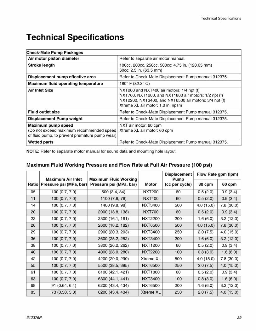
NOTE: Refer to separate motor manual for sound data and mounting hole layout.
Maximum Fluid Working Pressure and Flow Rate at Full Air Pressure (100 psi)
Check-Mate Pump PackagesAir motor piston diameter Refer to separate air motor manual.
Stroke length 100cc, 200cc, 250cc, 500cc: 4.75 in. (120.65 mm)60cc: 2.5 in. (63.5 mm)
Displacement pump effective area Refer to Check-Mate Displacement Pump manual 312375.
Maximum fluid operating temperature 180° F (82.3° C)
Air Inlet Size NXT200 and NXT400 air motors: 1/4 npt (f)NXT700, NXT1200, and NXT1800 air motors: 1/2 npt (f)NXT2200, NXT3400, and NXT6500 air motors: 3/4 npt (f)Xtreme XL air motor: 1.0 in. npsm
Fluid outlet size Refer to Check-Mate Displacement Pump manual 312375.
Displacement Pump weight Refer to Check-Mate Displacement Pump manual 312375.
Maximum pump speed(Do not exceed maximum recommended speed of fluid pump, to prevent premature pump wear)
NXT air motor: 60 cpmXtreme XL air motor: 60 cpm
Wetted parts Refer to Check-Mate Displacement Pump manual 312375.
RatioMaximum Air Inlet
Pressure psi (MPa, bar)Maximum Fluid Working Pressure psi (MPa, bar) Motor
Displacement Pump
(cc per cycle)
Flow Rate gpm (lpm)
30 cpm 60 cpm
05 100 (0.7, 7.0) 500 (3.4, 34) NXT200 60 0.5 (2.0) 0.9 (3.4)
11 100 (0.7, 7.0) 1100 (7.6, 76) NXT400 60 0.5 (2.0) 0.9 (3.4)
14 100 (0.7, 7.0) 1400 (9.8, 98) NXT3400 500 4.0 (15.0) 7.8 (30.0)
20 100 (0.7, 7.0) 2000 (13.8, 138) NXT700 60 0.5 (2.0) 0.9 (3.4)
23 100 (0.7, 7.0) 2300 (16.1, 161) NXT2200 200 1.6 (6.0) 3.2 (12.0)
26 100 (0.7, 7.0) 2600 (18.2, 182) NXT6500 500 4.0 (15.0) 7.8 (30.0)
29 100 (0.7, 7.0) 2900 (20.3, 203) NXT3400 250 2.0 (7.5) 4.0 (15.0)
36 100 (0.7, 7.0) 3600 (25.2, 252) NXT3400 200 1.6 (6.0) 3.2 (12.0)
38 100 (0.7, 7.0) 3800 (26.2, 262) NXT1200 60 0.5 (2.0) 0.9 (3.4)
40 100 (0.7, 7.0) 4000 (28.0, 280) NXT2200 100 0.8 (3.0) 1.6 (6.0)
42 100 (0.7, 7.0) 4200 (29.0, 290) Xtreme XL 500 4.0 (15.0) 7.8 (30.0)
55 100 (0.7, 7.0) 5500 (38.5, 385) NXT6500 250 2.0 (7.5) 4.0 (15.0)
61 100 (0.7, 7.0) 6100 (42.1, 421) NXT1800 60 0.5 (2.0) 0.9 (3.4)
63 100 (0.7, 7.0) 6300 (44.1, 441) NXT3400 100 0.8 (3.0) 1.6 (6.0)
68 91 (0.64, 6.4) 6200 (43.4, 434) NXT6500 200 1.6 (6.0) 3.2 (12.0)
85 73 (0.50, 5.0) 6200 (43.4, 434) Xtreme XL 250 2.0 (7.5) 4.0 (15.0)

All written and visual data contained in this document reflects the latest product information available at the time of publication. Graco reserves the right to make changes at any time without notice.
Original instructions. This manual contains English. MM 312376Graco Headquarters: Minneapolis
International Offices: Belgium, China, Japan, Korea
GRACO INC. AND SUBSIDIARIES • P.O. BOX 1441 • MINNEAPOLIS MN 55440-1441 • USACopyright 2018, Graco Inc. All Graco manufacturing locations are registered to ISO 9001.
www.graco.comRevision P, June 2018
Graco Standard WarrantyGraco warrants all equipment referenced in this document which is manufactured by Graco and bearing its name to be free from defects in material and workmanship on the date of sale to the original purchaser for use. With the exception of any special, extended, or limited warranty published by Graco, Graco will, for a period of twelve months from the date of sale, repair or replace any part of the equipment determined by Graco to be defective. This warranty applies only when the equipment is installed, operated and maintained in accordance with Graco’s written recommendations.
This warranty does not cover, and Graco shall not be liable for general wear and tear, or any malfunction, damage or wear caused by faulty installation, misapplication, abrasion, corrosion, inadequate or improper maintenance, negligence, accident, tampering, or substitution of non-Graco component parts. Nor shall Graco be liable for malfunction, damage or wear caused by the incompatibility of Graco equipment with structures, accessories, equipment or materials not supplied by Graco, or the improper design, manufacture, installation, operation or maintenance of structures, accessories, equipment or materials not supplied by Graco.
This warranty is conditioned upon the prepaid return of the equipment claimed to be defective to an authorized Graco distributor for verification of the claimed defect. If the claimed defect is verified, Graco will repair or replace free of charge any defective parts. The equipment will be returned to the original purchaser transportation prepaid. If inspection of the equipment does not disclose any defect in material or workmanship, repairs will be made at a reasonable charge, which charges may include the costs of parts, labor, and transportation.
THIS WARRANTY IS EXCLUSIVE, AND IS IN LIEU OF ANY OTHER WARRANTIES, EXPRESS OR IMPLIED, INCLUDING BUT NOT LIMITED TO WARRANTY OF MERCHANTABILITY OR WARRANTY OF FITNESS FOR A PARTICULAR PURPOSE.
Graco’s sole obligation and buyer’s sole remedy for any breach of warranty shall be as set forth above. The buyer agrees that no other remedy (including, but not limited to, incidental or consequential damages for lost profits, lost sales, injury to person or property, or any other incidental or consequential loss) shall be available. Any action for breach of warranty must be brought within two (2) years of the date of sale.
GRACO MAKES NO WARRANTY, AND DISCLAIMS ALL IMPLIED WARRANTIES OF MERCHANTABILITY AND FITNESS FOR A PARTICULAR PURPOSE, IN CONNECTION WITH ACCESSORIES, EQUIPMENT, MATERIALS OR COMPONENTS SOLD BUT NOT MANUFACTURED BY GRACO. These items sold, but not manufactured by Graco (such as electric motors, switches, hose, etc.), are subject to the warranty, if any, of their manufacturer. Graco will provide purchaser with reasonable assistance in making any claim for breach of these warranties.
In no event will Graco be liable for indirect, incidental, special or consequential damages resulting from Graco supplying equipment hereunder, or the furnishing, performance, or use of any products or other goods sold hereto, whether due to a breach of contract, breach of warranty, the negligence of Graco, or otherwise.
FOR GRACO CANADA CUSTOMERSThe Parties acknowledge that they have required that the present document, as well as all documents, notices and legal proceedings entered into, given or instituted pursuant hereto or relating directly or indirectly hereto, be drawn up in English. Les parties reconnaissent avoir convenu que la rédaction du présente document sera en Anglais, ainsi que tous documents, avis et procédures judiciaires exécutés, donnés ou intentés, à la suite de ou en rapport, directement ou indirectement, avec les procédures concernées.
Graco InformationFor the latest information about Graco products, visit www.graco.com.
For patent information, see www.graco.com/patents.
TO PLACE AN ORDER, contact your Graco distributor or call to identify the nearest distributor.Phone: 612-623-6921 or Toll Free: 1-800-328-0211 Fax: 612-378-3505