Embed Size (px)
Citation preview
1
ISOTHERMAL REACTOR DESIGN
In Chapter 1 & 2, we discussed balances on batch & flow reactors. In Chapter 3, we discussed rxns. Here, we will combine rxns and reactors.
TopicsPart 1: Mole Balances in Terms of Conversion
1. Algorithm for Isothermal Reactor Design 2. Applications/Examples of CRE Algorithm 3. Reversible Reactions 4. ODE Solutions to CRE Problems 5. General Guidelines for California Problems 6. PBR with Pressure Drop 7. Engineering Analysis
Part 2: Measures Other Than Conversion 1. Measures Other Than Conversion 2. Membrane Reactors 3. Semibatch Reactors
Part 1: Mole Balances in Terms of Conversion
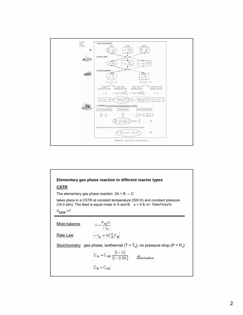
1. Algorithm for Isothermal Reactor Design
The algorithm for the pathway of interest can be summarized as:
1. Mole Balance and Design Equation (choose reactor type)
2. Rate Law (choose rxn type; gas or liq. phase)
3. Stoichiometry
4. Combine
5. Evaluate
The Evaluate Step can be carried out
A. Graphically (Plots)
B. Numerically (Quadrature Formulas)
C. Analytically (Integral tables)
D. Using Software Packages
2
Elementary gas phase reaction in different reactor types
CSTRThe elementary gas phase reaction 2A + B → C
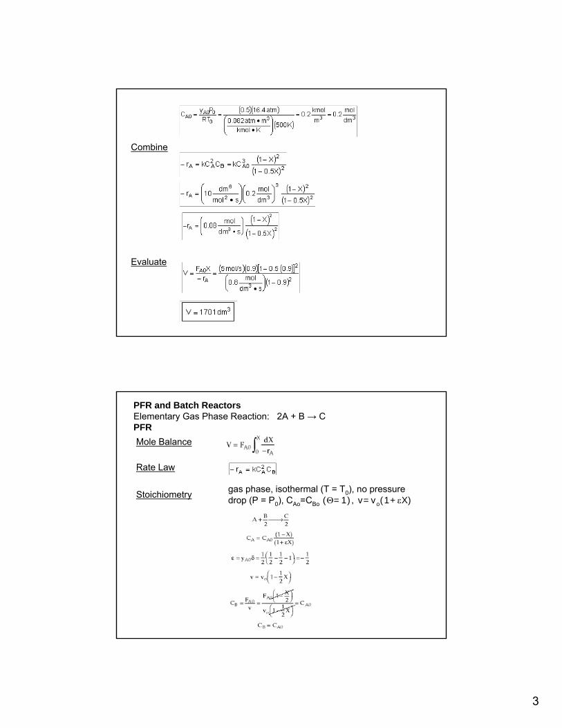
takes place in a CSTR at constant temperature (500 K) and constant pressure (16.4 atm). The feed is equal molar in A and B. x = 0.9, k= 10dm6/mol2s
VCSTR =?
Mole balance
Rate Law
Stoichiometry gas phase, isothermal (T = T0), no pressure drop (P = P0)
Derivation
3
Combine
Evaluate
PFR and Batch ReactorsElementary Gas Phase Reaction: 2A + B → CPFR Mole Balance
Rate Law
gas phase, isothermal (T = T0), no pressure drop (P = P0), CAo=CBo (Θ=1), v=vo(1+εX)
Stoichiometry
4
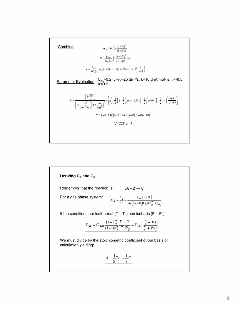
Combine
CAo=0.2, v=vo=25 dm3/s, k=10 dm6/mol2 s, ε=-0.5, X=0.9Parameter Evaluation
V=227 dm3
Remember that the reaction is:
For a gas phase system:
If the conditions are isothermal (T = T0) and isobaric (P = P0):
We must divide by the stoichiometric coefficient of our basis ofcalculation yielding:
Deriving CA and CB
5
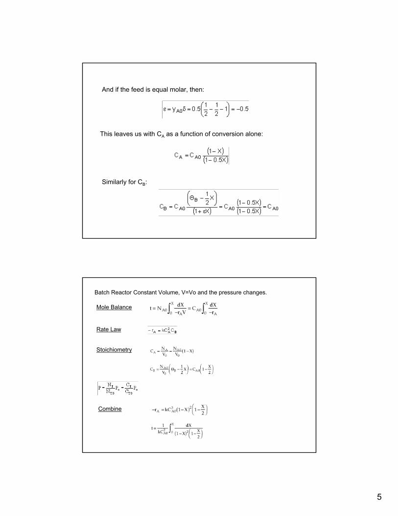
This leaves us with CA as a function of conversion alone:
Similarly for CB:
And if the feed is equal molar, then:
Batch Reactor Constant Volume, V=Vo and the pressure changes.
Mole Balance
Rate Law
Stoichiometry
Combine
6
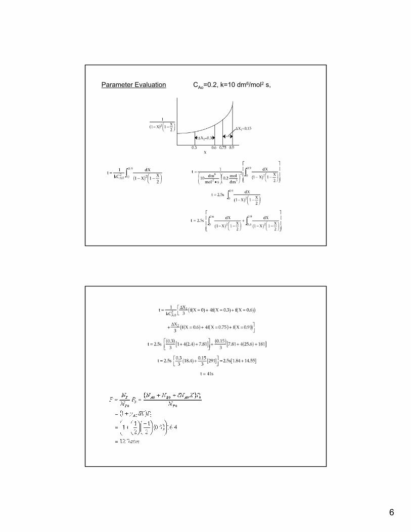
CAo=0.2, k=10 dm6/mol2 s,Parameter Evaluation
7
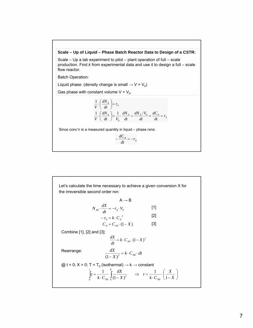
Scale – Up of Liquid – Phase Batch Reactor Data to Design of a CSTR:
Scale – Up a lab experiment to pilot – plant operation of full – scale production. Find k from experimental data and use it to design a full – scale flow reactor.
Batch Operation:
Liquid phase: (density change is small → V = V0)
Gas phase with constant volume V = V0.
AAAAA
AA
rdt
dCdt
VdNdt
dNVdt
dNV
rdt
dNV
===⋅=⎟⎠⎞
⎜⎝⎛⋅
=⎟⎠⎞
⎜⎝⎛⋅
0
0
/11
1
Since conc’n is a measured quantity in liquid – phase rxns:
AA r
dtdC
−=−
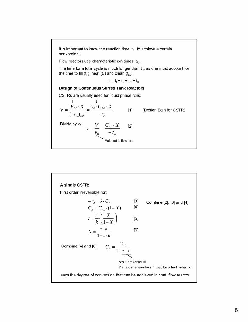
Let’s calculate the time necessary to achieve a given conversion X for the irreversible second order rxn:
A → B
)1(0
2
00
XCCCkr
VrdtdXN
AA
AA
AA
−⋅=⋅=−
⋅−=⋅ [1]
[2]
[3]
Combine [1], [2] and [3];2
0 )1( XCkdtdX
A −⋅⋅=
Rearrange: dtCkX
dXA ⋅⋅=
− 02)1(
@ t = 0; X = 0; T = T0 (isothermal) → k → constant
⎟⎠⎞
⎜⎝⎛−
⋅⋅
=⇒−⋅
= ∫∫ XX
Ckt
XdX
Ckt
A
X
A
t
11
)1(1
002
00
8
It is important to know the reaction time, tR, to achieve a certain conversion.
Flow reactors use characteristic rxn times, tR.
The time for a total cycle is much longer than tR, as one must account for the time to fill (tF), heat (th) and clean (tC).
t = tf + th + tC + tRDesign of Continuous Stirred Tank Reactors
CSTRs are usually used for liquid phase rxns:
A
A
exitA
A
rXCv
rXFV
−⋅⋅
=−
⋅= 000
)([1] (Design Eq’n for CSTR)
Divide by v0:
A
A
rXC
vV
−⋅
== 0
0
τ [2]
Volumetric flow rate
A single CSTR:
First order irreversible rxn:
kkX
XX
k
XCCCkr
AA
AA
⋅+⋅
=
⎟⎠⎞
⎜⎝⎛−
⋅=
−⋅=⋅=−
ττ
τ
1
11
)1(0
[3][4]
[5]
[6]
Combine [4] and [6]
Combine [2], [3] and [4]
kCC A
A ⋅+=
τ10
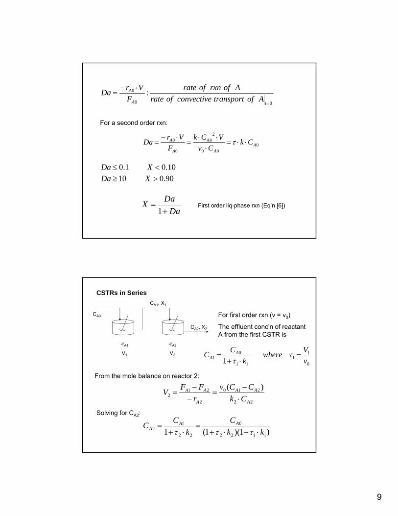
rxn Damköhler #,Da: a dimensionless # that for a first order rxn
says the degree of conversion that can be achieved in cont. flow reactor.
9
00
0 :=
⋅−=
tA
A
AoftransportconvectiveofrateAofrxnofrate
FVrDa
For a second order rxn:
000
20
0
0A
A
A
A
A CkCv
VCkF
VrDa ⋅⋅=⋅
⋅⋅=
⋅−= τ
90.01010.01.0
>≥<≤
XDaXDa
DaDaX+
=1
First order liq-phase rxn (Eq’n [6])
CSTRs in Series
CA0
CA1, X1
CA2, X2
-rA1
V1
-rA2
V2
For first order rxn (v = v0)
The effluent conc’n of reactant A from the first CSTR is
0
11
11
01 1 v
Vwherek
CC AA =
⋅+= τ
τ
From the mole balance on reactor 2:
22
210
2
212
)(
A
AA
A
AA
CkCCv
rFFV
⋅−
=−−
=
Solving for CA2:
)1)(1(1 1122
0
22
12 kk
Ck
CC AAA ⋅+⋅+
=⋅+
=τττ
10
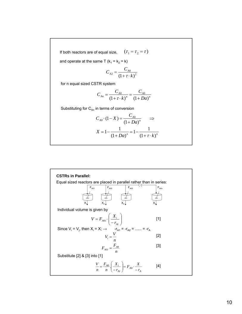
If both reactors are of equal size, )( 21 τττ ==
and operate at the same T (k1 = k2 = k)
20
2 )1( kCC A
A ⋅+=
τfor n equal sized CSTR system
nA
nA
An DaC
kCC
)1()1(00
+=
⋅+=
τ
Substituting for CAn in terms of conversion
nn
nA
A
kDaX
DaCXC
)1(11
)1(11
)1()1( 0
0
⋅+−=
+−=
⇒+
=−⋅
τ
CSTRs in Parallel:Equal sized reactors are placed in parallel rather than in series:
FA01
X1
FA02 FA03 FA0n
X2 X3 Xn
Individual volume is given by
⎟⎟⎠
⎞⎜⎜⎝
⎛−
⋅=Ai
iiA r
XFV 0 [1]
Since Vi = Vj, then Xi = X; → -rA1 = -rA2 = ...... = -rA
nFF
nVV
AiA
i
00 =
= [2]
[3]
AA
Ai
iA
rXF
rX
nF
nV
−⋅=⎟⎟
⎠
⎞⎜⎜⎝
⎛−
= 00 .
Substitute [2] & [3] into [1]
[4]
11
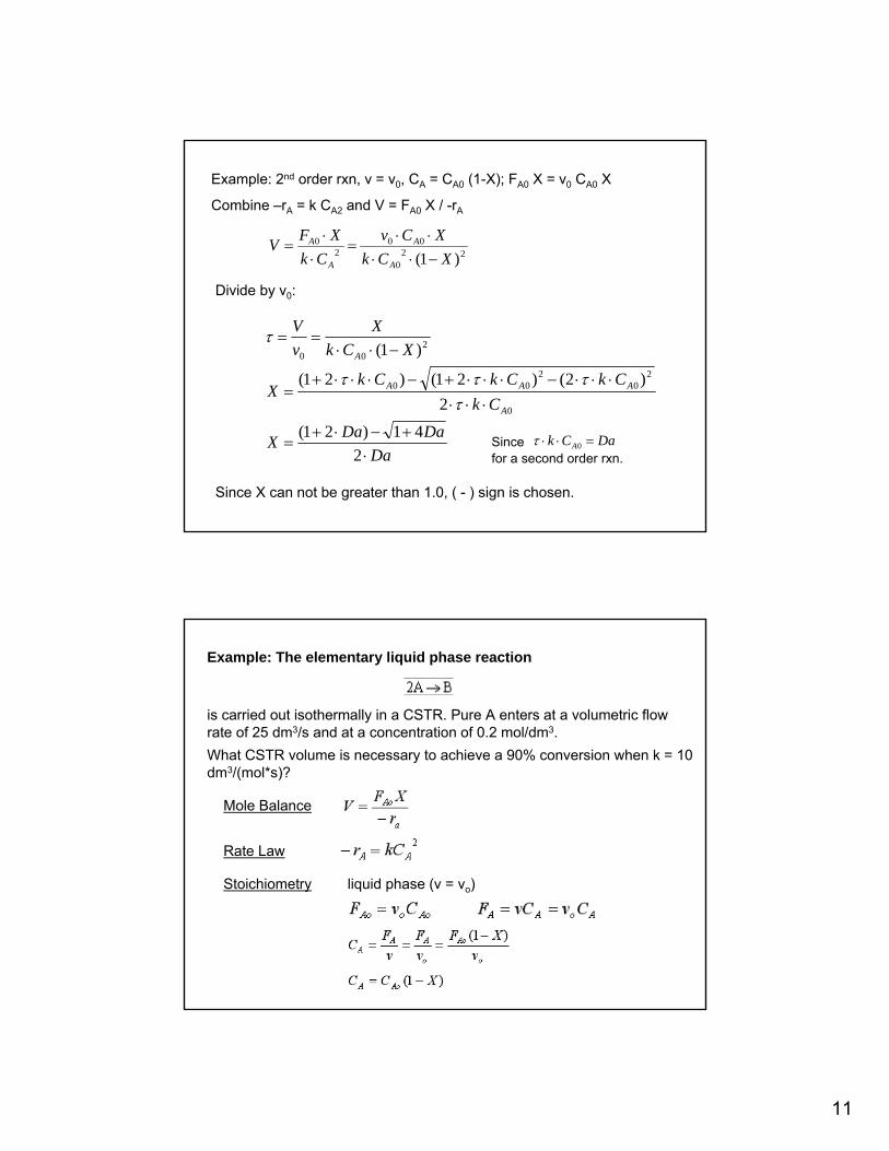
Example: 2nd order rxn, v = v0, CA = CA0 (1-X); FA0 X = v0 CA0 X
Combine –rA = k CA2 and V = FA0 X / -rA
220
002
0
)1( XCkXCv
CkXFV
A
A
A
A
−⋅⋅⋅⋅
=⋅⋅
=
Divide by v0:
DaDaDaX
CkCkCkCk
X
XCkX
vV
A
AAA
A
⋅+−⋅+
=
⋅⋅⋅⋅⋅⋅−⋅⋅⋅+−⋅⋅⋅+
=
−⋅⋅==
241)21(
2)2()21()21(
)1(
0
20
200
200
ττττ
τ
Since DaCk A =⋅⋅ 0τfor a second order rxn.
Since X can not be greater than 1.0, ( - ) sign is chosen.
Example: The elementary liquid phase reaction
is carried out isothermally in a CSTR. Pure A enters at a volumetric flow rate of 25 dm3/s and at a concentration of 0.2 mol/dm3. What CSTR volume is necessary to achieve a 90% conversion when k = 10 dm3/(mol*s)?
Mole Balance
Rate Law
Stoichiometry liquid phase (v = vo)
12
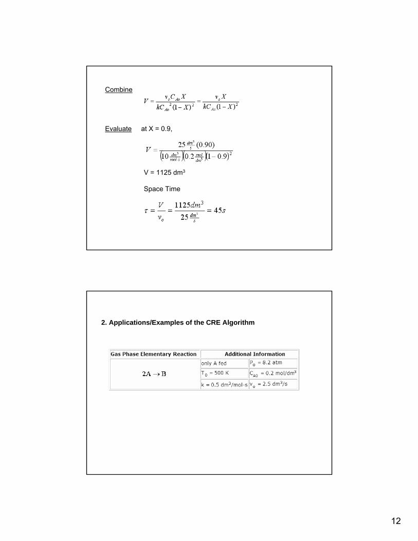
Combine
Evaluate at X = 0.9,
V = 1125 dm3
Space Time
2. Applications/Examples of the CRE Algorithm

13
Applying the algorithm to the above reaction occuring in Batch, CSTR, PFR
14
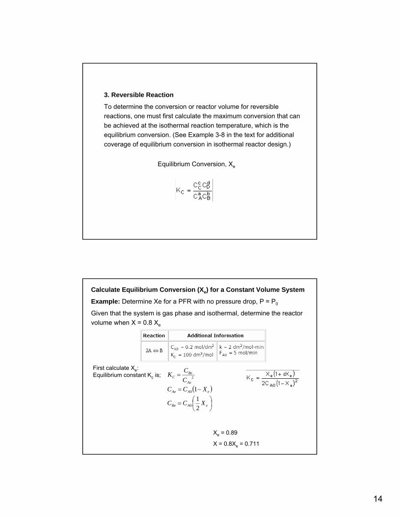
3. Reversible Reaction
To determine the conversion or reactor volume for reversible reactions, one must first calculate the maximum conversion that can be achieved at the isothermal reaction temperature, which is theequilibrium conversion. (See Example 3-8 in the text for additional coverage of equilibrium conversion in isothermal reactor design.)
Equilibrium Conversion, Xe
Calculate Equilibrium Conversion (Xe) for a Constant Volume System
Example: Determine Xe for a PFR with no pressure drop, P = P0
Given that the system is gas phase and isothermal, determine the reactor volume when X = 0.8 Xe
First calculate Xe:Equilibrium constant Kc is;
Xe = 0.89
X = 0.8Xe = 0.711
( )
⎟⎠⎞
⎜⎝⎛=
−=
=
eABe
eAAe
Ae
BeC
XCC
XCCCCK
21
1
0
0
2
15
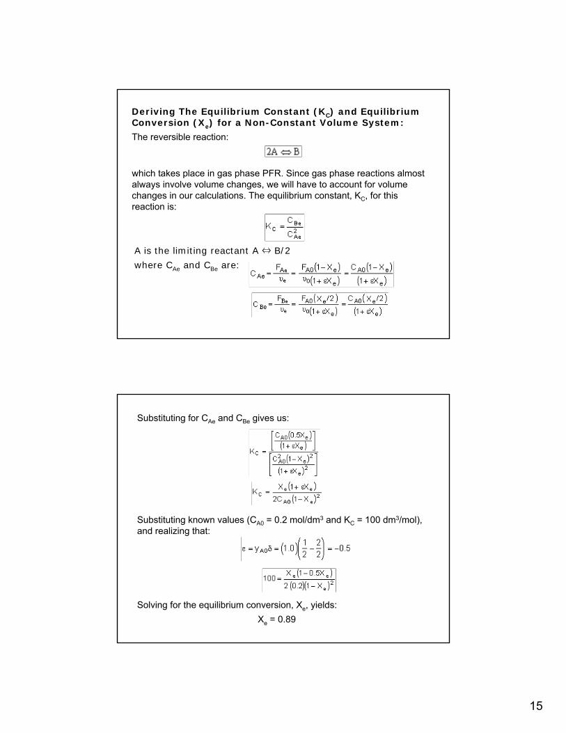
Deriving The Equilibrium Constant (KC) and Equilibrium Conversion (Xe) for a Non-Constant Volume System:
The reversible reaction:
which takes place in gas phase PFR. Since gas phase reactions almost always involve volume changes, we will have to account for volume changes in our calculations. The equilibrium constant, KC, for this reaction is:
where CAe and CBe are:
A is the limiting reactant A ⇔ B/2
Substituting for CAe and CBe gives us:
Substituting known values (CA0 = 0.2 mol/dm3 and KC = 100 dm3/mol), and realizing that:
Xe = 0.89Solving for the equilibrium conversion, Xe, yields:
16
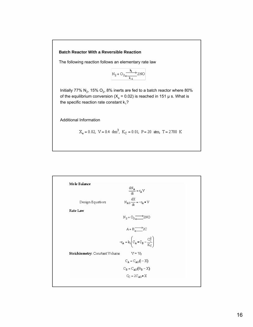
Batch Reactor With a Reversible Reaction
The following reaction follows an elementary rate law
Initially 77% N2, 15% O2, 8% inerts are fed to a batch reactor where 80% of the equilibrium conversion (Xe = 0.02) is reached in 151 µ s. What is the specific reaction rate constant k1?
Additional Information
17
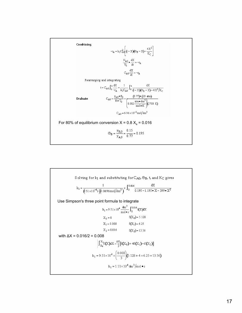
For 80% of equilibrium conversion X = 0.8 Xe = 0.016
Use Simpson's three point formula to integrate
with ∆X = 0.016/2 = 0.008
18
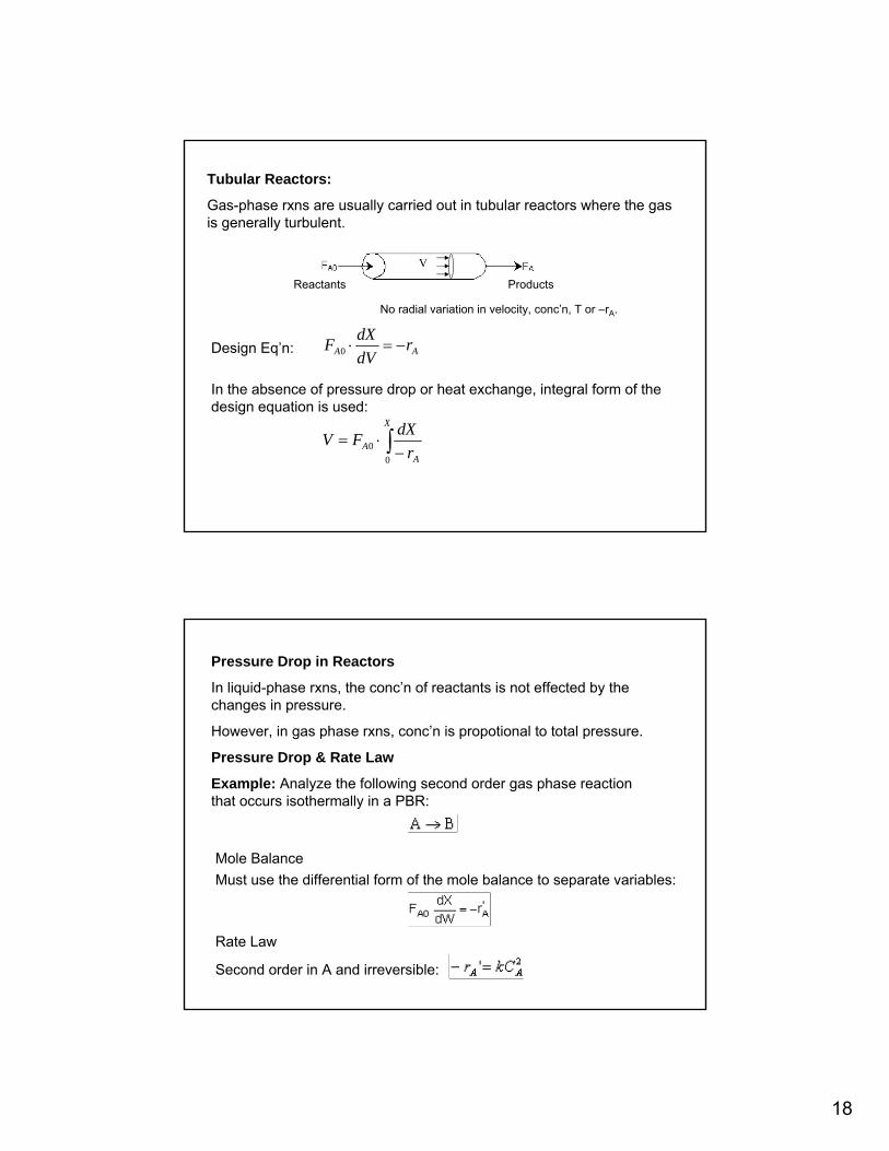
Tubular Reactors:
Gas-phase rxns are usually carried out in tubular reactors where the gas is generally turbulent.
Reactants Products
No radial variation in velocity, conc’n, T or –rA.
Design Eq’n: AA rdVdXF −=⋅0
In the absence of pressure drop or heat exchange, integral form of the design equation is used:
∫ −⋅=X
AA r
dXFV0
0
Pressure Drop in Reactors
In liquid-phase rxns, the conc’n of reactants is not effected by the changes in pressure.
However, in gas phase rxns, conc’n is propotional to total pressure.
Pressure Drop & Rate Law
Example: Analyze the following second order gas phase reaction that occurs isothermally in a PBR:
Mole Balance Must use the differential form of the mole balance to separate variables:
Rate Law
Second order in A and irreversible:
19
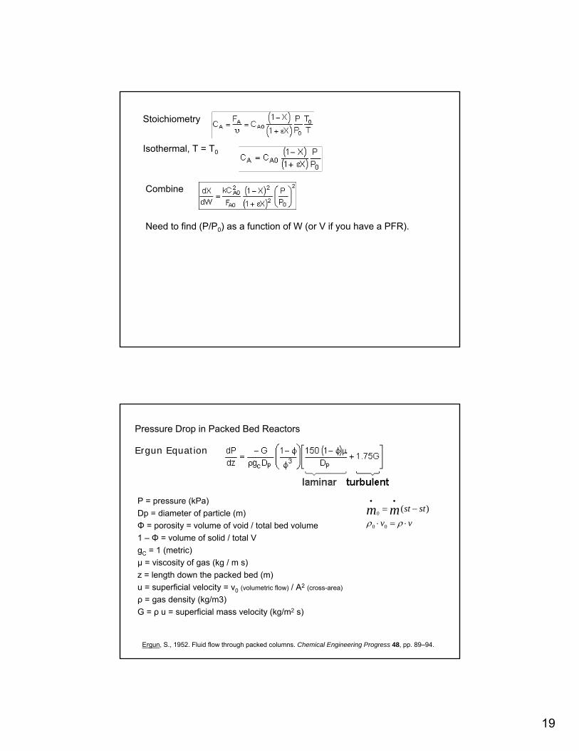
Stoichiometry
Isothermal, T = T0
Combine
Need to find (P/P0) as a function of W (or V if you have a PFR).
Pressure Drop in Packed Bed Reactors
Ergun Equation
P = pressure (kPa)Dp = diameter of particle (m)Φ = porosity = volume of void / total bed volume1 – Φ = volume of solid / total VgC = 1 (metric)µ = viscosity of gas (kg / m s)z = length down the packed bed (m)u = superficial velocity = v0 (volumetric flow) / A2 (cross-area)
ρ = gas density (kg/m3)G = ρ u = superficial mass velocity (kg/m2 s)
vvststmm
⋅=⋅
−=••
ρρ 00
0)(
Ergun, S., 1952. Fluid flow through packed columns. Chemical Engineering Progress 48, pp. 89–94.
20
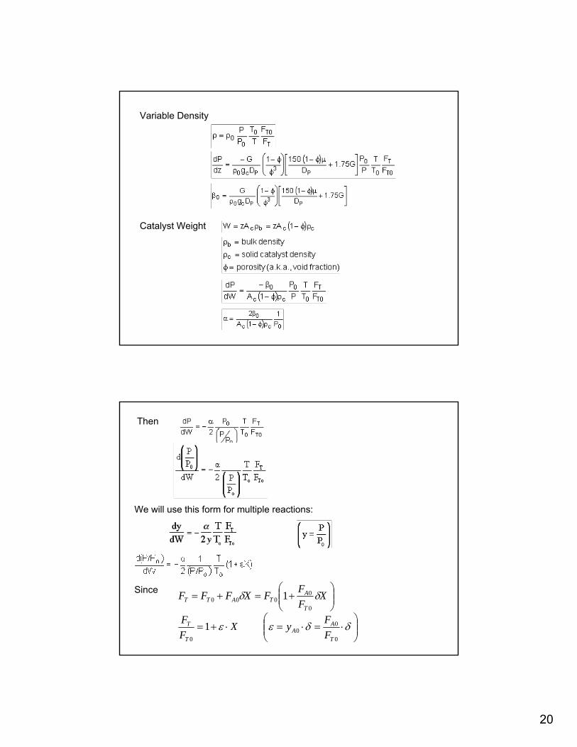
Variable Density
Catalyst Weight
Then
We will use this form for multiple reactions:
⎟⎟⎠
⎞⎜⎜⎝
⎛⋅=⋅=⋅+=
⎟⎟⎠
⎞⎜⎜⎝
⎛+=+=
δδεε
δδ
0
00
0
0
0000
1
1
T
AA
T
T
T
ATATT
FFyX
FF
XFFFXFFFSince
21
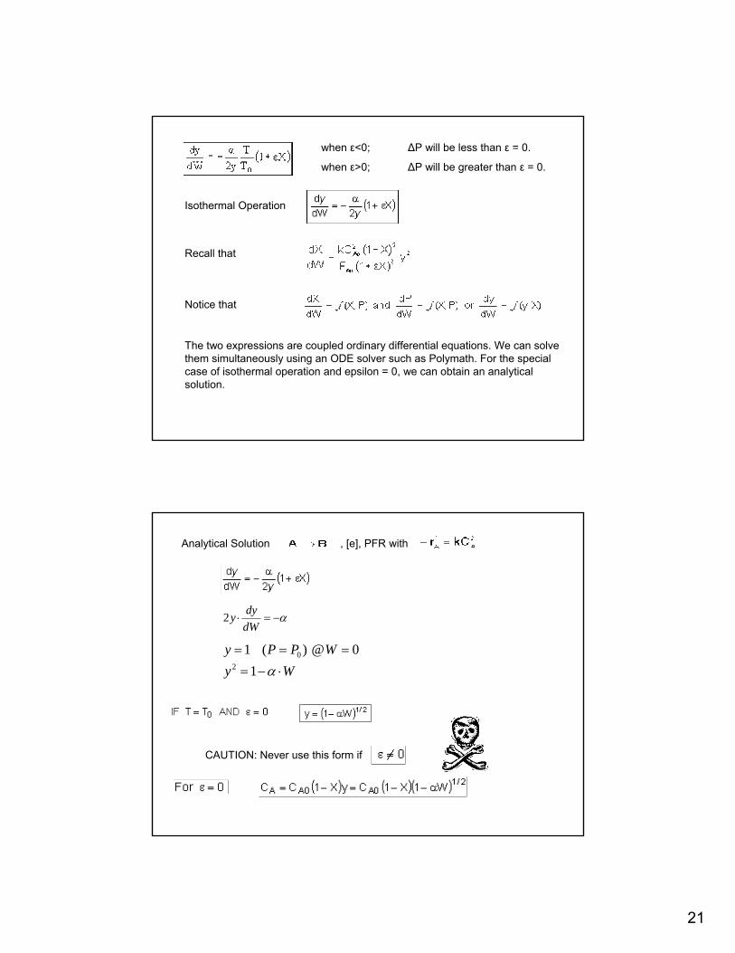
when ε<0; ∆P will be less than ε = 0.
when ε>0; ∆P will be greater than ε = 0.
Isothermal Operation
Recall that
Notice that
The two expressions are coupled ordinary differential equations. We can solve them simultaneously using an ODE solver such as Polymath. For the special case of isothermal operation and epsilon = 0, we can obtain an analytical solution.
Analytical Solution , [e], PFR with
α−=⋅dWdyy2
WyWPPy
⋅−=
===
α10@)(1
20
CAUTION: Never use this form if
22
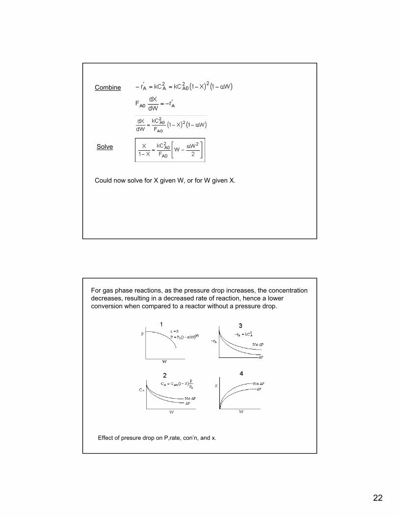
Combine
Solve
Could now solve for X given W, or for W given X.
For gas phase reactions, as the pressure drop increases, the concentration decreases, resulting in a decreased rate of reaction, hence a lower conversion when compared to a reactor without a pressure drop.
Effect of presure drop on P,rate, con’n, and x.
23
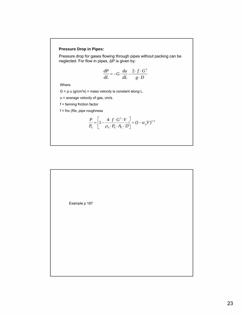
Pressure Drop in Pipes:
Pressure drop for gases flowing through pipes without packing can be neglected. For flow in pipes, ∆P is given by:
DgGf
dLduG
dLdP
⋅⋅⋅
−⋅−=22
Where
G = ρ u (g/cm3s) = mass velocity is constant along L.
u = average velocity of gas, cm/s.
f = fanning friction factor
f = fnc (Re, pipe roughness
2/1
00
2
0
)1(41 VDAP
VGfPP
pC
αρ
−=⎥⎦
⎤⎢⎣
⎡⋅⋅⋅⋅⋅⋅
−=
Example p 187
24
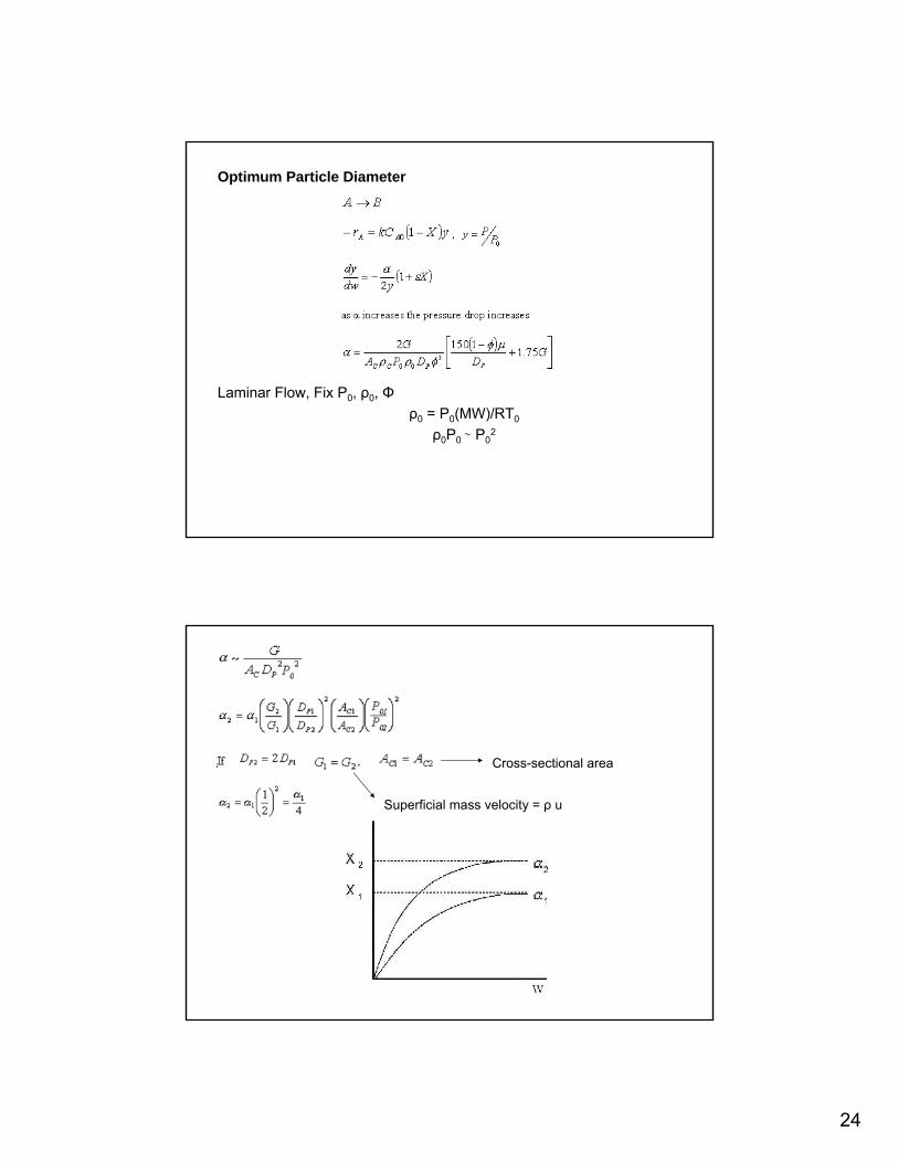
Optimum Particle Diameter
Laminar Flow, Fix P0, ρ0, Φρ0 = P0(MW)/RT0
ρ0P0 ∼ P02
Superficial mass velocity = ρ u
Cross-sectional area
25
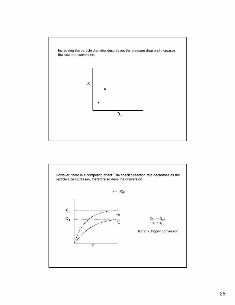
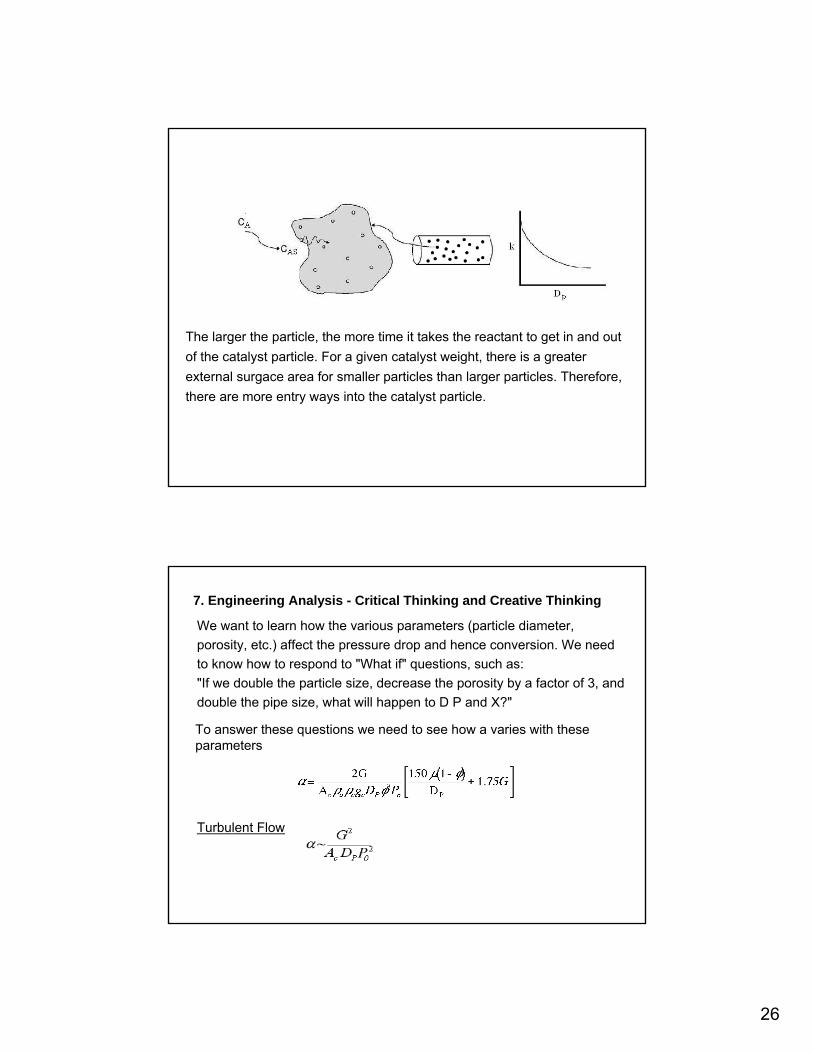
Increasing the particle diameter descreases the pressure drop and increases the rate and conversion.
DP1 > DP2k1 > k2
Higher k, higher conversion
However, there is a competing effect. The specific reaction rate decreases as the particle size increases, therefore so deos the conversion.
k ∼ 1/Dp
26
The larger the particle, the more time it takes the reactant to get in and out of the catalyst particle. For a given catalyst weight, there is a greater external surgace area for smaller particles than larger particles. Therefore, there are more entry ways into the catalyst particle.
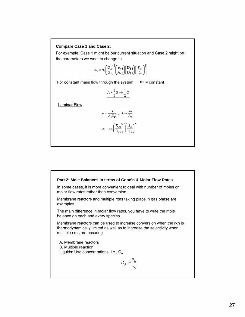
7. Engineering Analysis - Critical Thinking and Creative Thinking
We want to learn how the various parameters (particle diameter, porosity, etc.) affect the pressure drop and hence conversion. We need to know how to respond to "What if" questions, such as:"If we double the particle size, decrease the porosity by a factor of 3, and double the pipe size, what will happen to D P and X?"
To answer these questions we need to see how a varies with theseparameters
Turbulent Flow
27
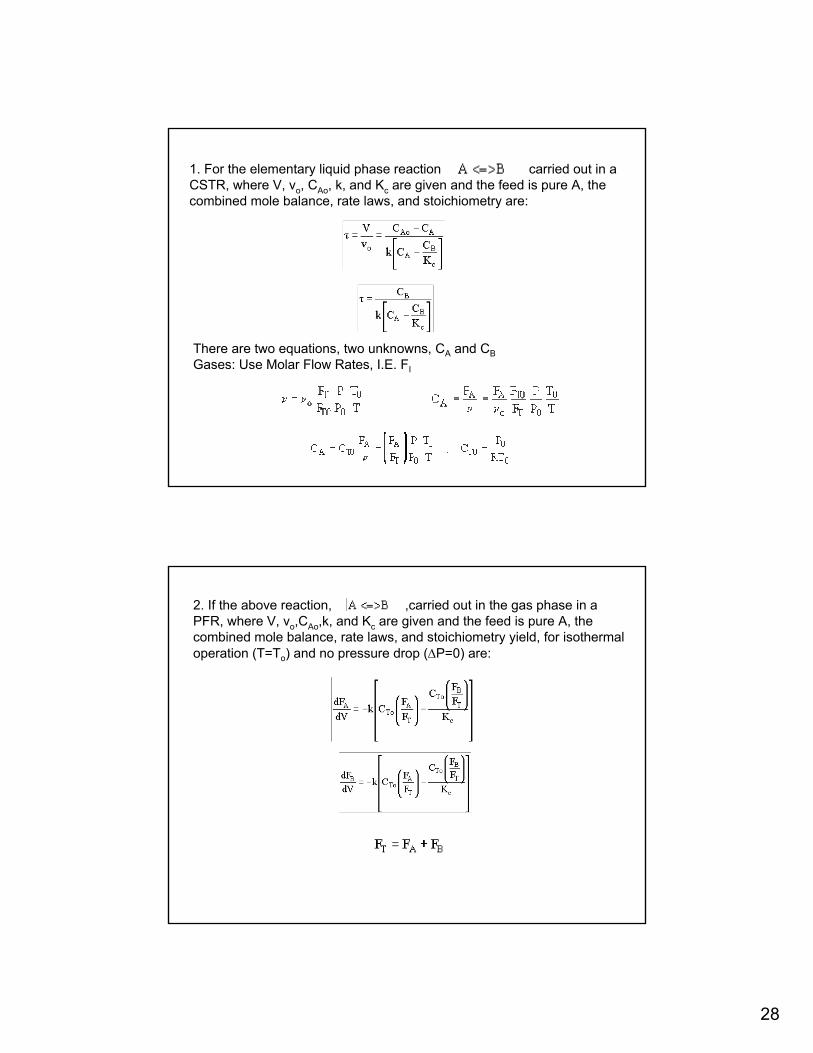
Compare Case 1 and Case 2:For example, Case 1 might be our current situation and Case 2 might be the parameters we want to change to.
For constant mass flow through the system = constant
Laminar Flow
Part 2: Mole Balances in terms of Conc’n & Molar Flow Rates
In some cases, it is more convenient to deal with number of moles or molar flow rates rather than conversion.
Membrane reactors and multiple rxns taking place in gas phase are examples.
The main difference in molar flow rates, you have to write the mole balance on each and every species.
Membrane reactors can be used to increase conversion when the rxn is thermodynamically limited as well as to increase the selectivity when multiple rxns are occuring.
A. Membrane reactorsB. Multiple reactionLiquids: Use concentrations, i.e., CA
28
1. For the elementary liquid phase reaction carried out in a CSTR, where V, vo, CAo, k, and Kc are given and the feed is pure A, the combined mole balance, rate laws, and stoichiometry are:
There are two equations, two unknowns, CA and CBGases: Use Molar Flow Rates, I.E. FI
2. If the above reaction, ,carried out in the gas phase in a PFR, where V, vo,CAo,k, and Kc are given and the feed is pure A, the combined mole balance, rate laws, and stoichiometry yield, for isothermal operation (T=To) and no pressure drop (∆P=0) are:
29
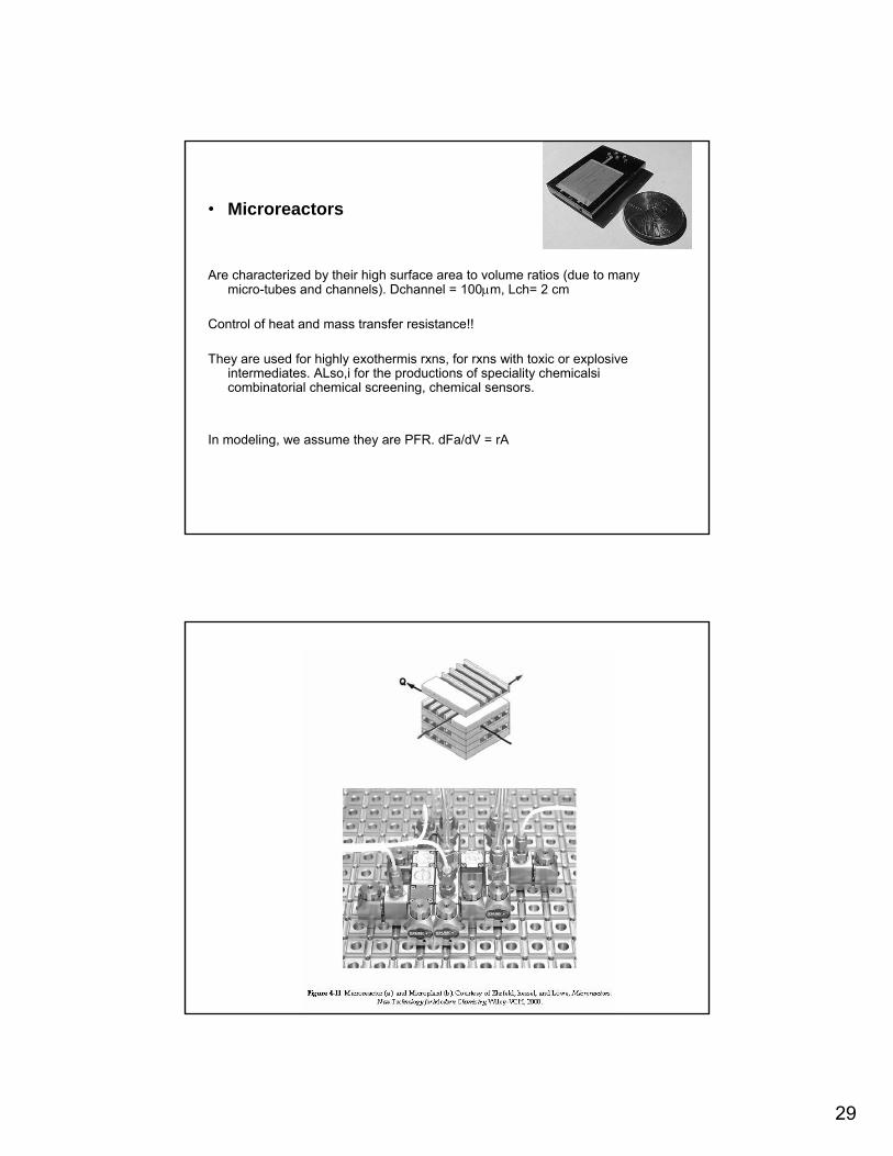
• Microreactors
Are characterized by their high surface area to volume ratios (due to many micro-tubes and channels). Dchannel = 100µm, Lch= 2 cm
Control of heat and mass transfer resistance!!
They are used for highly exothermis rxns, for rxns with toxic or explosive intermediates. ALso,i for the productions of speciality chemicalsi combinatorial chemical screening, chemical sensors.
In modeling, we assume they are PFR. dFa/dV = rA
30
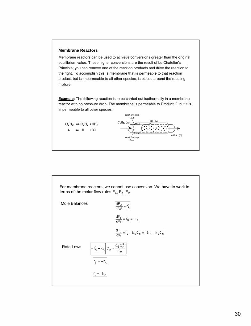
Membrane ReactorsMembrane reactors can be used to achieve conversions greater than the original equilibrium value. These higher conversions are the result of Le Chatelier's Principle; you can remove one of the reaction products and drive the reaction to the right. To accomplish this, a membrane that is permeable to that reaction product, but is impermeable to all other species, is placed around the reacting mixture.
Example: The following reaction is to be carried out isothermally in a membrane reactor with no pressure drop. The membrane is permeable to Product C, but it is impermeable to all other species.
For membrane reactors, we cannot use conversion. We have to work in terms of the molar flow rates FA, FB, FC.
Mole Balances
Rate Laws
31
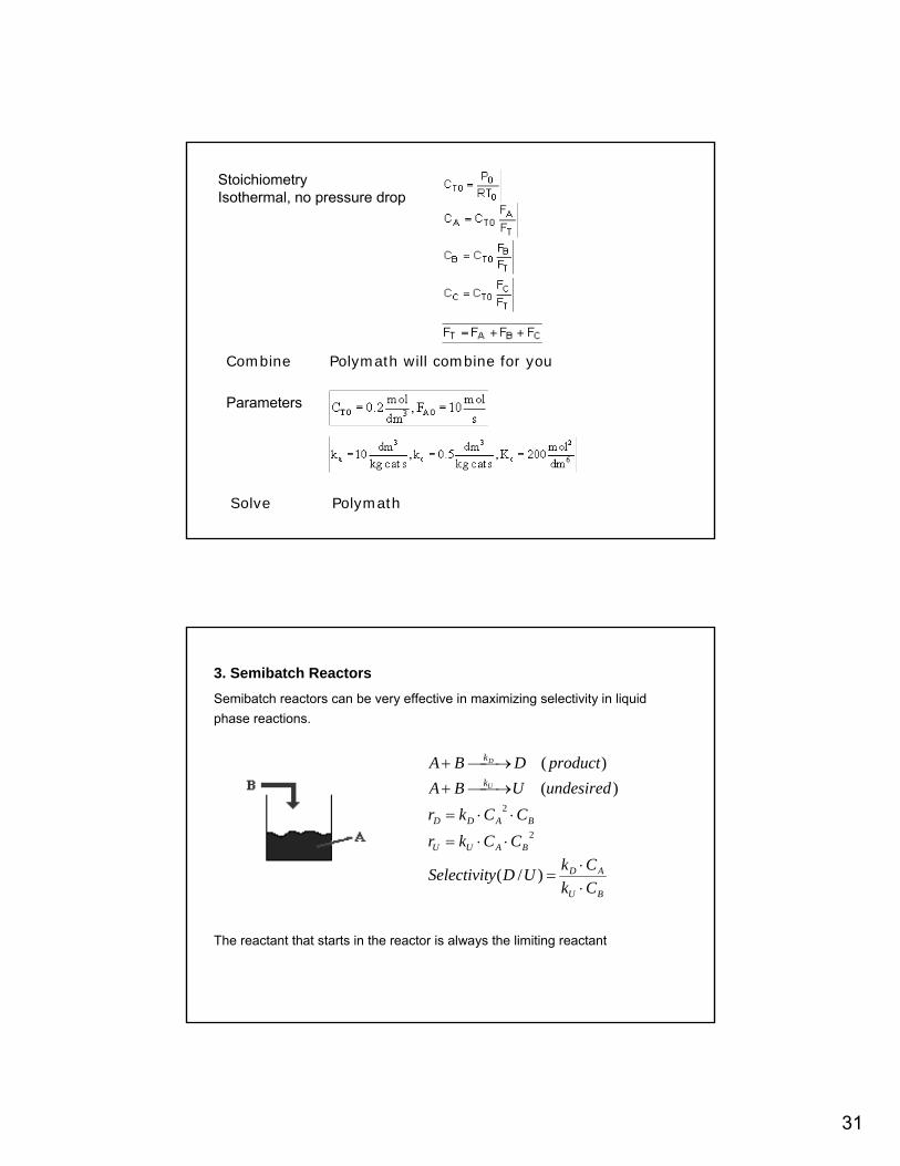
StoichiometryIsothermal, no pressure drop
Polymath will combine for youCombine
Parameters
Polymath Solve
3. Semibatch Reactors Semibatch reactors can be very effective in maximizing selectivity in liquid phase reactions.
The reactant that starts in the reactor is always the limiting reactant
BU
AD
BAUU
BADD
k
k
CkCkUDySelectivit
CCkrCCkr
undesiredUBAproductDBA
U
D
⋅⋅
=
⋅⋅=
⋅⋅=
⎯→⎯+
⎯→⎯+
)/(
)()(
2
2
32
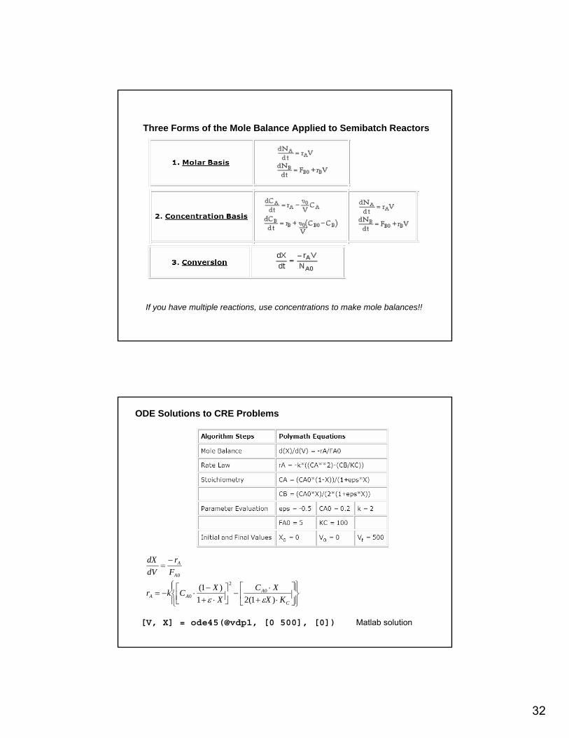
Three Forms of the Mole Balance Applied to Semibatch Reactors
If you have multiple reactions, use concentrations to make mole balances!!
ODE Solutions to CRE Problems
⎪⎭
⎪⎬⎫
⎪⎩
⎪⎨⎧
⎥⎦
⎤⎢⎣
⎡⋅+
⋅−⎥⎦
⎤⎢⎣⎡
⋅+−
⋅−=
−=
C
AAA
A
A
KXXC
XXCkr
Fr
dVdX
)1(21)1( 0
2
0
0
εε
[V, X] = ode45(@vdp1, [0 500], [0]) Matlab solution
33
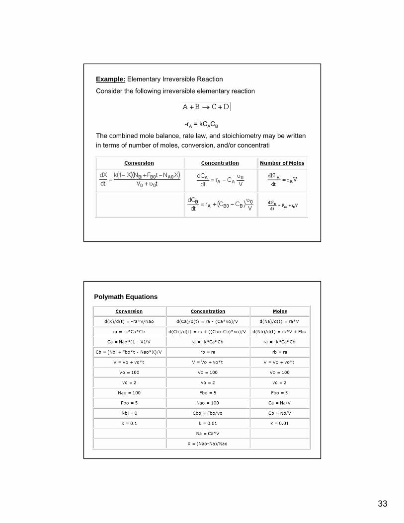
Example: Elementary Irreversible Reaction
Consider the following irreversible elementary reaction
-rA = kCACB
The combined mole balance, rate law, and stoichiometry may be written in terms of number of moles, conversion, and/or concentrati
Polymath Equations
34
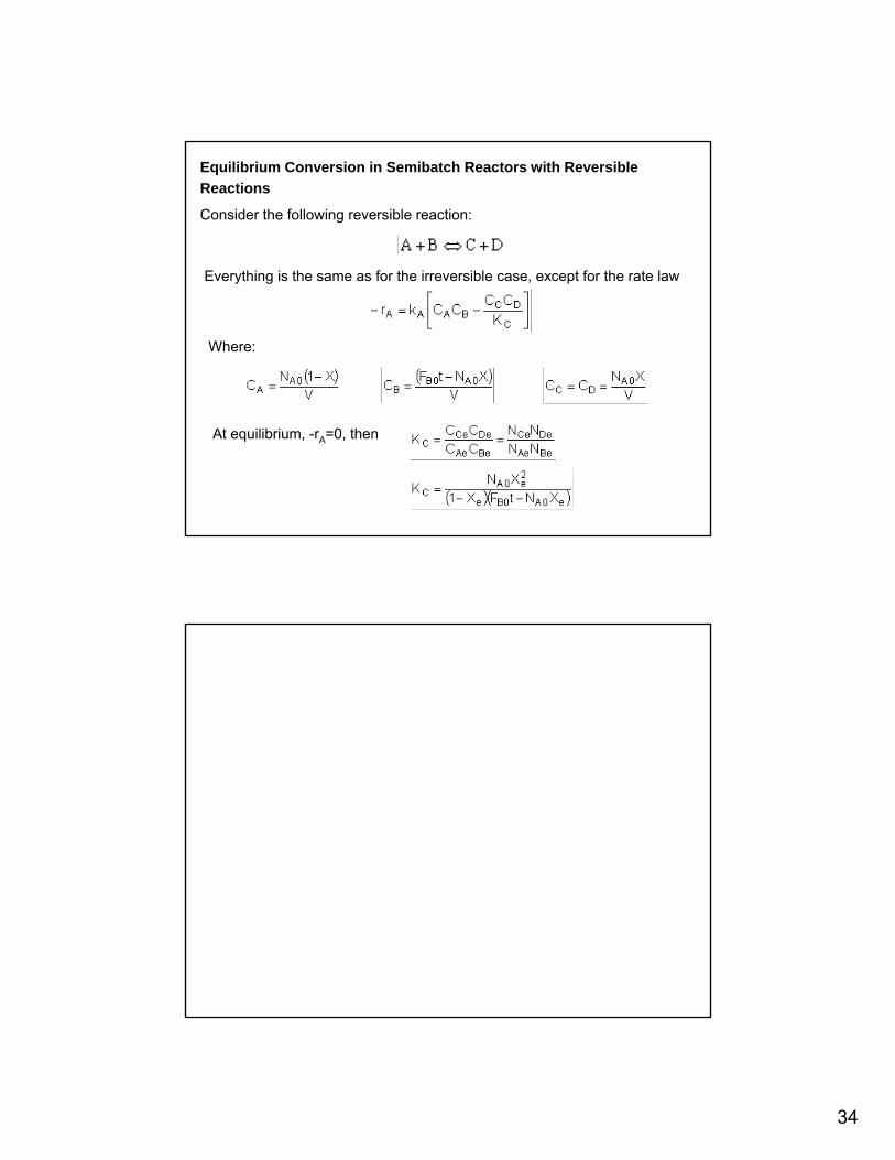
Equilibrium Conversion in Semibatch Reactors with Reversible Reactions
Consider the following reversible reaction:
Everything is the same as for the irreversible case, except for the rate law
Where:
At equilibrium, -rA=0, then
35
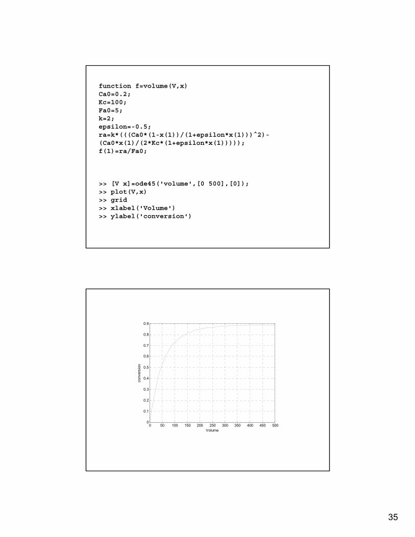
function f=volume(V,x)Ca0=0.2;Kc=100;Fa0=5;k=2;epsilon=-0.5;ra=k*(((Ca0*(1-x(1))/(1+epsilon*x(1)))^2)-(Ca0*x(1)/(2*Kc*(1+epsilon*x(1)))));f(1)=ra/Fa0;
>> [V x]=ode45('volume',[0 500],[0]);>> plot(V,x)>> grid>> xlabel('Volume')>> ylabel('conversion')
0 50 100 150 200 250 300 350 400 450 5000
0.1
0.2
0.3
0.4
0.5
0.6
0.7
0.8
0.9
Volume
conv
ersi
on
36
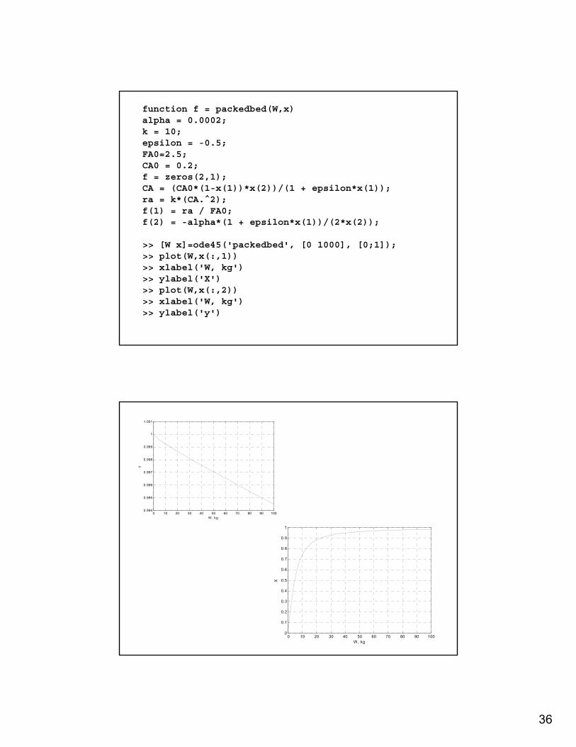
function f = packedbed(W,x)alpha = 0.0002;k = 10;epsilon = -0.5;FA0=2.5;CA0 = 0.2;f = zeros(2,1);CA = (CA0*(1-x(1))*x(2))/(1 + epsilon*x(1));ra = k*(CA.^2);f(1) = ra / FA0;f(2) = -alpha*(1 + epsilon*x(1))/(2*x(2));
>> [W x]=ode45('packedbed', [0 1000], [0;1]);>> plot(W,x(:,1))>> xlabel('W, kg')>> ylabel('X')>> plot(W,x(:,2))>> xlabel('W, kg')>> ylabel('y')
0 10 20 30 40 50 60 70 80 90 1000
0.1
0.2
0.3
0.4
0.5
0.6
0.7
0.8
0.9
1
X
W, kg
0 10 20 30 40 50 60 70 80 90 1000.994
0.995
0.996
0.997
0.998
0.999
1
1.001
W, kg
y
37
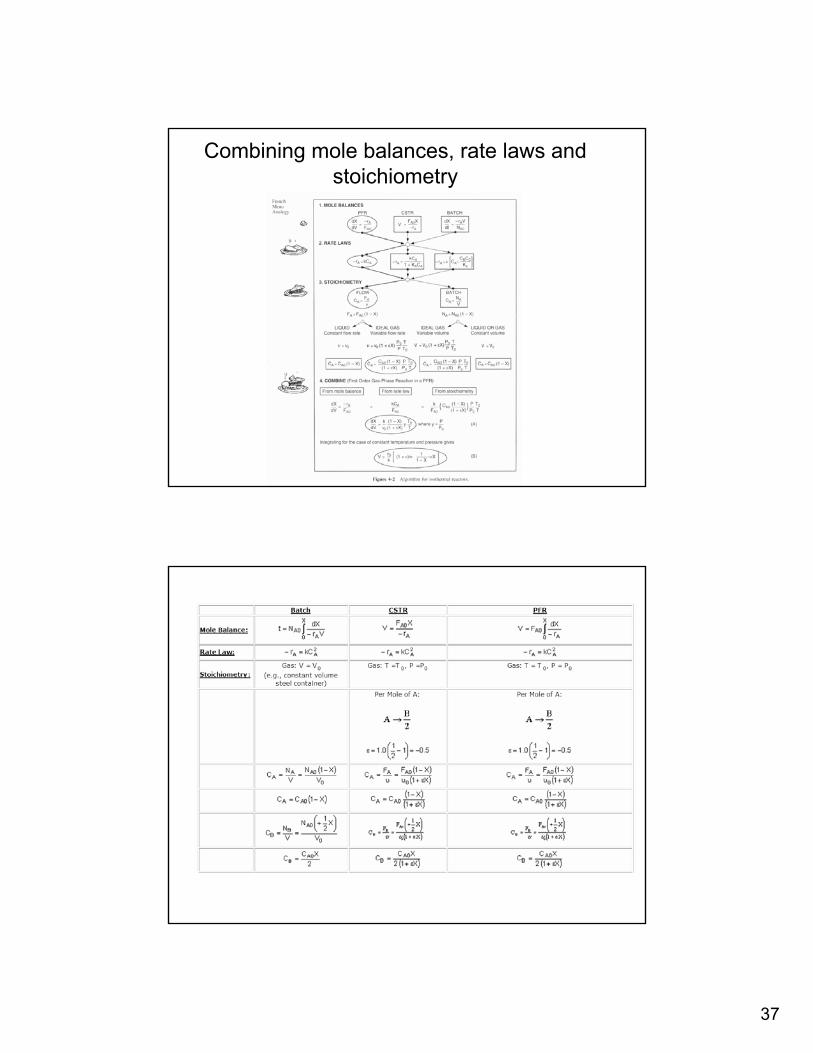
Combining mole balances, rate laws and stoichiometry
38
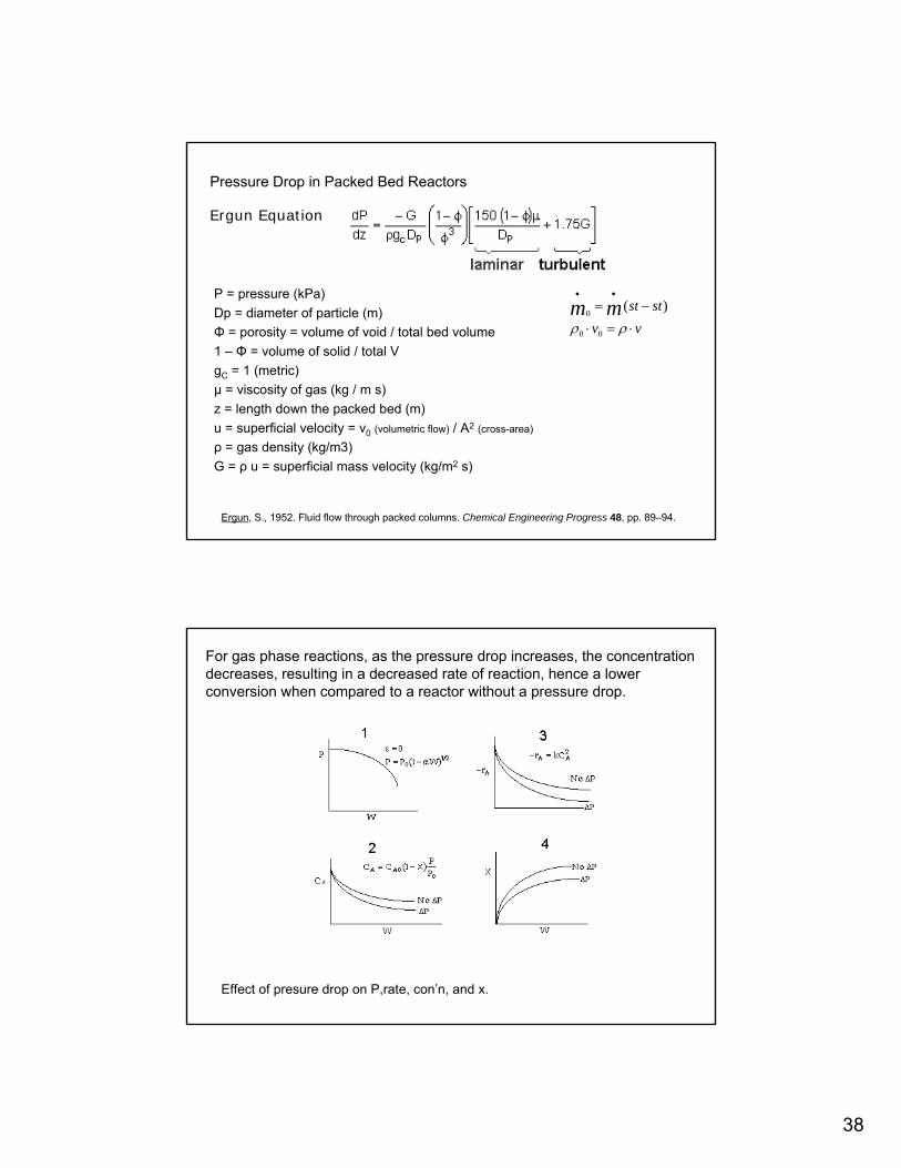
Pressure Drop in Packed Bed Reactors
Ergun Equation
P = pressure (kPa)Dp = diameter of particle (m)Φ = porosity = volume of void / total bed volume1 – Φ = volume of solid / total VgC = 1 (metric)µ = viscosity of gas (kg / m s)z = length down the packed bed (m)u = superficial velocity = v0 (volumetric flow) / A2 (cross-area)
ρ = gas density (kg/m3)G = ρ u = superficial mass velocity (kg/m2 s)
vvststmm
⋅=⋅
−=••
ρρ 00
0)(
Ergun, S., 1952. Fluid flow through packed columns. Chemical Engineering Progress 48, pp. 89–94.
For gas phase reactions, as the pressure drop increases, the concentration decreases, resulting in a decreased rate of reaction, hence a lower conversion when compared to a reactor without a pressure drop.
Effect of presure drop on P,rate, con’n, and x.

39
Part 2: Mole Balances in terms of Conc’n & Molar Flow RatesIn some cases, it is more convenient to deal with number of moles or molar flow rates rather than conversion.
Membrane reactors and multiple rxns taking place in gas phase are examples.Microreactors with multiple reactions