Embed Size (px)
Citation preview

CHASING EME: ARGUMENTS FOR AN
END-MIDDLE-END INTERNET
A Dissertation
Presented to the Faculty of the Graduate School
of Cornell University
in Partial Fulfillment of the Requirements for the Degree of
Doctor of Philosophy
by
Saikat Guha
August 2009

c© 2009 Saikat Guha
ALL RIGHTS RESERVED

CHASING EME: ARGUMENTS FOR AN END-MIDDLE-END INTERNET
Saikat Guha, Ph.D.
Cornell University 2009
Connection establishment in the Internet has remained unchanged from its orig-
inal design in the 1970s: first, the path between the communicating endpoints
is assumed to always be open. It is assumed that an endpoint can reach any
other endpoint by simply sending a packet addressed to the destination. This
assumption is no longer borne out in practice: Network Address Translators
(NATs) prevent all hosts from being addressed, firewalls prevent all packets
from being delivered, and middleboxes transparently intercept packets with-
out endpoint knowledge. Second, the Internet strives to deliver all packets ad-
dressed to a destination regardless of whether the packet is ultimately desired
by the destination or not. Denial of Service (DoS) attacks are therefore common-
place, and the Internet remains vulnerable to flash worms.
This thesis presents the End-Middle-End (EME) requirements for connec-
tion establishment that the modern Internet should satisfy, and explores the de-
sign space of a signaling-based architecture that meets these requirements with
minimal changes to the existing Internet. In so doing, this thesis proposes so-
lutions to three real-world problems. First, it focuses on the problem of TCP
NAT Traversal, where endpoints behind their respective NATs today cannot es-
tablish a direct TCP connection with each other due to default NAT behavior.
It presents a set of techniques, called STUNT, that solves this problem without
any changes to NATs or to existing operating systems. In STUNT, the commu-
nicating endpoints use signaling to coordinate the creation of NAT state that
then enables a direct TCP connection. The second problem this thesis focuses
on is that of mitigating unwanted traffic on the Internet, such as DoS attacks
and worms, originating from botnets. It presents a simple architecture, called
ShutUp, that mitigates unwanted traffic in a completely End-to-End (E2E) man-
ner without requiring any changes to the network. Trusted code near the source
of unwanted traffic, for instance in the virtualization layer, network card, or
nearby router, responds to signals from the destination by taking corrective ac-
tion. Finally, this thesis focuses on the broader problem of establishing con-
nections that adhere to all applicable network policy, including access control,
multihomed route control, andmiddlebox usage— all open problems in today’s
Internet. This thesis presents the NUTSS architecture which takes into account
policy set by all stakeholders, including both the endpoints and the middle net-
works. NUTSS uses name-based signaling to negotiate high-level policy before
connection establishment, and couples it to address-based signaling for efficient
enforcement during the connection lifetime. NUTSS does not change the proto-
col stack and can be deployed incrementally.
Solving each of the aforementioned problems requires a departure from the
original Internet architecture. Yet in this thesis clean-slate solutions are ex-
pressly avoided in favor of evolutionary changes. The central argument of this
thesis is that solving a wide range of architectural shortcomings of today’s In-
ternet, and incremental deployment are not mutually exclusive.
BIOGRAPHICAL SKETCH
Saikat Guha seeks nothing short of world domination through the blunt instru-
ment of research in network systems. Following in the footsteps of his role
models Dr. Evil, Dr. Doom, and Dr. Octopus (that may or may not be his nick-
names for his committee members), he sought out his B.S., M.S., and Ph.D. in
Computer Science from Cornell University in 2003, 2008, and 2009 respectively.
Prior to escaping to Cornell, he spent the first year of his undergraduate in-
carceration at the Indian Institute of Technology (IIT) Delhi sentenced to study
Chemical Engineering. Having established his base of operations at Cornell,
Saikat reached out for venture capital: DoCoMo Labs introduced him to the
evils of Peer-to-Peer (P2P) technology in the summer of 2005. This brought him
to the attention of the evil empire, which offered him an internship at Microsoft
Research Cambridge in summer 2006 where he worked on more P2P stuff. He
finally graduated to the most evil of them all, Google Inc., where in the summer
of 2007 he worked on projects too evil to put in print. Meanwhile at Cornell, he
repeatedly broke the Internet architecture and put it back together, most notably
having to do with NAT Traversal, which gained him notoriety in the IETF and
the research community. With graduation imminent, Saikat evaluated the Max
Planck Institute for Software Systems (MPI-SWS) in Germany as a potential new
base of operations in the summer of 2008, and found it suitable for a temporary
post-doctoral position. From there he plans to launch the privacy preserving ad-
vertising revolution, which would unseat the evil advertising overlord Google
from its absolute monarchy over cloud computing. He then plans to ally with
his enemy’s enemy to re-imagine cloud computing so it protects user privacy,
thereby winning over legions of delighted users who will naturally deliver him
the world.
iii

To Ma, Bapi, Didu, and Mashi.
iv

ACKNOWLEDGEMENTS
Paul Francis, my advisor, taught me everything I know of architecting systems.
He ingrained in me the principle that a good architecture is not one which has
the most features, but one that meets the requirements with the fewest mech-
anisms. He constantly challenged me to reach higher, to solve a problem with
fewer assumptions, or with more severe constraints. Above all, Paul taught me
to be an independent researcher. He taught me to look for problems with real-
world significance, and to solve them in a way that would create real-world
impact. At the same time, Paul illustrated, by example, the role of an ideal
mentor. His hands-off nature encouraged me to find my own way, while his
endless patience, eye for detail, and brutal honesty made discussions with him
my first recourse in times of doubt. I will especially treasure every hard-fought
argument where I successfully defended my own for the thrill and sense of ac-
complishment it brought.
AndrewMyers cultivated the love of teaching in me. Emin Gun Sirer taught
memuch about the art of presenting one’s research to an audience. Fred Schnei-
der was a source of infallible wisdom and insight in analyzing and providing
constructive criticism on research. Neil Daswani at DoCoMo Labs and Google,
Pablo Rodriguez at Microsoft Research, and Nina Taft, Dina Papagiannaki, and
Jaideep Chandrasekhar at Intel Research gave me the opportunity to expand
my research interests and experience research from the industry perspective.
My internship with Krishna Gummadi at MPI-SWS and the Glasnost team un-
der him (Marcel Dischinger, Ratul Mahajan, Stefan Sariou, and Bryan Ford) was
an enriching collaborative experience.
Research cannot be done in isolation, and I owe a big debt to my many
cohabitants in the Cornell Systems Lab (Syslab). Under the stewardship of
v

Andrew Myers, Emin Gun Sirer, Ken Birman, and Johannes Gerkhe, the lab
brought together Ph.D. students from different areas under one roof. The Sys-
lab community was an invaluable resource in matters of research (and life in
general). Permanent Syslab residents: Hitesh Ballani, Oliver Kennedy, Jed Liu,
Alan Shieh, Krishnaprasad Vikram, Vivek Vishnumurthy, Dan Williams, and
Bernard Wong, and visitors: Mahesh Balakrishnan, Tuan Cao, Lakshmi Ganesh,
Tudor Marian, Patrick Reynolds, Yee Jiun Song, and Kevin Walsh were good
company through the years. I will cherish the late hours spent discussing re-
search on whiteboards, followed soon after by movies and takeout.
Finally, none of this would have been possible without the love and support
of my family. From introducing me to computer programming at the age of six,
to encouraging my obsession ever since, to supporting my decision to transfer
from IIT Delhi to a university in another country, my parents, my (late) grand-
mother, andmy aunt have been instrumental in enabling me to follow my every
dream, and to them I dedicate this thesis.
vi

TABLE OF CONTENTS
Biographical Sketch . . . . . . . . . . . . . . . . . . . . . . . . . . . . . . iiiDedication . . . . . . . . . . . . . . . . . . . . . . . . . . . . . . . . . . . ivAcknowledgements . . . . . . . . . . . . . . . . . . . . . . . . . . . . . . vTable of Contents . . . . . . . . . . . . . . . . . . . . . . . . . . . . . . . viiList of Tables . . . . . . . . . . . . . . . . . . . . . . . . . . . . . . . . . . ixList of Figures . . . . . . . . . . . . . . . . . . . . . . . . . . . . . . . . . x
1 Introduction 11.1 Clean Slate, Patches, or Evolution? . . . . . . . . . . . . . . . . . . 31.2 Using Signaling for Internet Connection Establishment . . . . . . 5
1.2.1 STUNT: NAT Traversal . . . . . . . . . . . . . . . . . . . . 91.2.2 ShutUp: Reducing Unwanted Traffic . . . . . . . . . . . . . 101.2.3 NUTSS: End-Middle-End Connection Establishment . . . 11
1.3 Evolving the Real-World Internet . . . . . . . . . . . . . . . . . . . 12
2 STUNT: Restoring Global Connectivity Through NATs 142.1 TCP NAT-Traversal . . . . . . . . . . . . . . . . . . . . . . . . . . . 17
2.1.1 STUNT . . . . . . . . . . . . . . . . . . . . . . . . . . . . . . 182.1.2 NATBlaster . . . . . . . . . . . . . . . . . . . . . . . . . . . 202.1.3 Peer-to-Peer NAT (P2PNAT) . . . . . . . . . . . . . . . . . 212.1.4 Implementation . . . . . . . . . . . . . . . . . . . . . . . . . 22
2.2 Experiment Setup . . . . . . . . . . . . . . . . . . . . . . . . . . . . 242.3 NAT TCP Characteristics . . . . . . . . . . . . . . . . . . . . . . . . 27
2.3.1 NATMapping . . . . . . . . . . . . . . . . . . . . . . . . . . 282.3.2 Endpoint Filtering . . . . . . . . . . . . . . . . . . . . . . . 332.3.3 Packet Mangling . . . . . . . . . . . . . . . . . . . . . . . . 372.3.4 TCP Timers . . . . . . . . . . . . . . . . . . . . . . . . . . . 37
2.4 Port Prediction . . . . . . . . . . . . . . . . . . . . . . . . . . . . . . 392.4.1 Effect of Port-Prediction Vulnerability Window . . . . . . . 422.4.2 Problems . . . . . . . . . . . . . . . . . . . . . . . . . . . . . 46
2.5 TCP Establishment . . . . . . . . . . . . . . . . . . . . . . . . . . . 482.5.1 Implementation . . . . . . . . . . . . . . . . . . . . . . . . . 51
2.6 Related Work . . . . . . . . . . . . . . . . . . . . . . . . . . . . . . 532.7 Conclusion and Future Work . . . . . . . . . . . . . . . . . . . . . 54
3 ShutUp: Reducing Unwanted Traffic 563.1 ShutUp Details . . . . . . . . . . . . . . . . . . . . . . . . . . . . . 61
3.1.1 ShutUp Components . . . . . . . . . . . . . . . . . . . . . . 613.1.2 Basic Operation . . . . . . . . . . . . . . . . . . . . . . . . . 633.1.3 SM Operation . . . . . . . . . . . . . . . . . . . . . . . . . . 643.1.4 NM Operation . . . . . . . . . . . . . . . . . . . . . . . . . 733.1.5 Protecting the SM . . . . . . . . . . . . . . . . . . . . . . . . 74
vii
3.1.6 Deployment . . . . . . . . . . . . . . . . . . . . . . . . . . . 753.2 Attacking ShutUp . . . . . . . . . . . . . . . . . . . . . . . . . . . . 753.3 Stopping DoS with ShutUp . . . . . . . . . . . . . . . . . . . . . . 793.4 Slowing Scanning Worms . . . . . . . . . . . . . . . . . . . . . . . 843.5 Evaluation . . . . . . . . . . . . . . . . . . . . . . . . . . . . . . . . 87
3.5.1 Tuning Parameters . . . . . . . . . . . . . . . . . . . . . . . 893.5.2 False Positives . . . . . . . . . . . . . . . . . . . . . . . . . . 92
3.6 Extensions to ShutUp . . . . . . . . . . . . . . . . . . . . . . . . . . 933.7 Related Work . . . . . . . . . . . . . . . . . . . . . . . . . . . . . . 943.8 Summary . . . . . . . . . . . . . . . . . . . . . . . . . . . . . . . . . 96
4 NUTSS: End-Middle-End Connection Establishment 984.1 NUTSS Architecture . . . . . . . . . . . . . . . . . . . . . . . . . . 103
4.1.1 NUTSS Overview . . . . . . . . . . . . . . . . . . . . . . . . 1034.1.2 Naming and Access Control . . . . . . . . . . . . . . . . . . 1064.1.3 Name-routed Signaling . . . . . . . . . . . . . . . . . . . . 1074.1.4 Address-routed Messages . . . . . . . . . . . . . . . . . . . 1154.1.5 Security Considerations . . . . . . . . . . . . . . . . . . . . 1174.1.6 Incremental Deployment . . . . . . . . . . . . . . . . . . . 1204.1.7 An Example: Asymmetric Routing through Firewalls . . . 121
4.2 Using and Extending NUTSS . . . . . . . . . . . . . . . . . . . . . 1234.2.1 Mobility . . . . . . . . . . . . . . . . . . . . . . . . . . . . . 1244.2.2 Legacy NAT Traversal . . . . . . . . . . . . . . . . . . . . . 1244.2.3 Endpoint-Imposed Middleboxes . . . . . . . . . . . . . . . 1254.2.4 Application-Level Anycast . . . . . . . . . . . . . . . . . . 1264.2.5 Negotiating Multicast . . . . . . . . . . . . . . . . . . . . . 1274.2.6 Default-Off . . . . . . . . . . . . . . . . . . . . . . . . . . . 1274.2.7 Protocol Negotiation . . . . . . . . . . . . . . . . . . . . . . 1284.2.8 Optimizations . . . . . . . . . . . . . . . . . . . . . . . . . . 129
4.3 Implementation . . . . . . . . . . . . . . . . . . . . . . . . . . . . . 1304.3.1 Findings . . . . . . . . . . . . . . . . . . . . . . . . . . . . . 133
4.4 Related Work . . . . . . . . . . . . . . . . . . . . . . . . . . . . . . 1354.5 Summary . . . . . . . . . . . . . . . . . . . . . . . . . . . . . . . . . 137
5 Impact 1385.1 BEHAVE-TCP: Standardizing NAT TCP Behavior . . . . . . . . . 1395.2 ICE-TCP: TCP NAT Traversal . . . . . . . . . . . . . . . . . . . . . 1415.3 EMERG: End-Middle-End Research Group . . . . . . . . . . . . . 141
6 Summary and the Road Forward 1436.1 The Real Challenge in Evolving the Internet . . . . . . . . . . . . . 145
Bibliography 147
viii
LIST OF TABLES
2.1 NAT, Network, and Implementation Issues . . . . . . . . . . . . . 232.2 NATs Tested . . . . . . . . . . . . . . . . . . . . . . . . . . . . . . . 262.3 NAT Vendor Market Share . . . . . . . . . . . . . . . . . . . . . . 272.4 NAT Parameters . . . . . . . . . . . . . . . . . . . . . . . . . . . . 282.5 NATMapping Classification . . . . . . . . . . . . . . . . . . . . . 292.6 NATMapping Observed . . . . . . . . . . . . . . . . . . . . . . . 322.7 NAT Filtering Classification . . . . . . . . . . . . . . . . . . . . . . 342.8 NAT Filtering Observed . . . . . . . . . . . . . . . . . . . . . . . . 352.9 NAT TCP Compliance Observed . . . . . . . . . . . . . . . . . . . 362.10 Survey of Computers Owned . . . . . . . . . . . . . . . . . . . . . 46
3.1 ShutUp Protocol . . . . . . . . . . . . . . . . . . . . . . . . . . . . 633.2 ShutUp State Maintained . . . . . . . . . . . . . . . . . . . . . . . 643.3 ShutUp Impact on Legitimate Connections . . . . . . . . . . . . . 91
4.1 NUTSS Protocol . . . . . . . . . . . . . . . . . . . . . . . . . . . . 1054.2 NUTSS Example Protocol Exchange . . . . . . . . . . . . . . . . . 1224.3 NUTSS API . . . . . . . . . . . . . . . . . . . . . . . . . . . . . . . 130
ix

LIST OF FIGURES
1.1 Signaling Design Space . . . . . . . . . . . . . . . . . . . . . . . . 8
2.1 STUNT Approach #1 . . . . . . . . . . . . . . . . . . . . . . . . . . 182.2 STUNT Approach #2 . . . . . . . . . . . . . . . . . . . . . . . . . . 192.3 NATBlaster Approach . . . . . . . . . . . . . . . . . . . . . . . . . 202.4 P2PNAT Approach . . . . . . . . . . . . . . . . . . . . . . . . . . . 212.5 Composite NAT Example . . . . . . . . . . . . . . . . . . . . . . . 252.6 NATMapping Test . . . . . . . . . . . . . . . . . . . . . . . . . . . 302.7 NAT Filtering Test . . . . . . . . . . . . . . . . . . . . . . . . . . . 332.8 NAT Timers Test . . . . . . . . . . . . . . . . . . . . . . . . . . . . 382.9 NAT Port-Prediction . . . . . . . . . . . . . . . . . . . . . . . . . . 402.10 CDF of Traffic Bursts . . . . . . . . . . . . . . . . . . . . . . . . . . 432.11 Port-Prediction Success Estimation . . . . . . . . . . . . . . . . . . 452.12 Issues with Port-Prediction . . . . . . . . . . . . . . . . . . . . . . 472.13 Success of TCP NAT Traversal Approaches . . . . . . . . . . . . . 492.14 NAT Traversal Test Setup . . . . . . . . . . . . . . . . . . . . . . . 512.15 NAT Traversal Delay . . . . . . . . . . . . . . . . . . . . . . . . . . 52
3.1 Basic ShutUp Operation . . . . . . . . . . . . . . . . . . . . . . . . 583.2 ShutUp Component Placement . . . . . . . . . . . . . . . . . . . . 623.3 ShutUp DoS Mitigation Simulation . . . . . . . . . . . . . . . . . 823.4 ShutUp Time Taken to Stop DoS . . . . . . . . . . . . . . . . . . . 833.5 ShutUp Worm Mitigation Simulation . . . . . . . . . . . . . . . . 863.6 Selecting ShutUp Timers . . . . . . . . . . . . . . . . . . . . . . . 90
4.1 NUTSS Example Network Topology . . . . . . . . . . . . . . . . . 1074.2 NUTSS Endpoint Registration . . . . . . . . . . . . . . . . . . . . 1104.3 NUTSS Flow Negotiation . . . . . . . . . . . . . . . . . . . . . . . 1134.4 NUTSS On-Path Signaling . . . . . . . . . . . . . . . . . . . . . . 1154.5 NUTSS Asymmetric Routing Example . . . . . . . . . . . . . . . 121
x

CHAPTER 1
INTRODUCTION
The Internet was designed to provide a small but critical set of transport
services:
1. User-friendly naming of all Internet hosts (through DNS).
2. Network-level identification of all Internet hosts (through the IP address) and
best-effort delivery of datagrams to identified hosts.
3. Identification of the application on the host that should receive a given packet
(through the port number).
Implicit among these serviceswas the idea that applications would individu-
ally take care of access control. The Internet1 would deliver transmitted packets
to the target application, and it was up to the application to decide whether to
accept or reject the packet. A further implication of this approach is that there is
no danger in asking an application to process an incoming packet. The applica-
tion is assumed to be competent to look inside the packet and decide whether
or not to accept it. Industry recognized in the early 90’s that this approach was
wrong: DoS attacks can overwhelm an application, and because of either bugs
or just poor design, applications are incapable of securing themselves with cer-
tainty. The industry answer to this problem was the firewall, which effectively
enunciated a fourth critical requirement for the Internet transport service:
1By “Internet”, we mean the naming and transport services provided by IP ad-dresses, ports, and DNS for today’s “fixed” Internet (including wireless access to thewired Internet). Sensor networks and MANETs that perform their own naming androuting separate from the Internet are not included in this definition.
1
4. Blocking of unwanted packets before they reach the target application
(through packet filters in firewalls).
Of course it is well-known that the Internet today is ill-equipped to sat-
isfy these four core requirements. The IP address shortage prevents all hosts
from being identifiable in the network. Port numbers do not adequately iden-
tify applications anywhere outside of the operating system (OS) that created
the socket. As a result, firewalls cannot be certain what application is behind
a given port number. Thus firewals tend to use costly deep packet inspection,
and often err on the side of caution (preventing flows that might otherwise be
acceptable).
The firewall compromised the End-to-End (E2E) [103] nature of the Internet
architecture by placing a point of control outside of the end host. While this
development was widely viewed as negative [49], we and others [127] believe
that it is not only inevitable, but necessary and largely positive. A primary
reason for this is the fact that there may be multiple legitimate stakeholders in
a given packet flow—the end user, the corporate IT department, or the ISP—
each with their own policies. The E2E nature of the Internet does not easily
accommodate these policies. Another reason, however, is that sometimes it is
simply economically expedient to deploy a function in the middle, even if it
might ultimately be better done at the ends. Today there are often good reasons
to want to route packets through middleboxes other than firewalls: for instance,
virus scanners, web caches, traffic shapers, performance enhancing proxies and
protocol translators (IPv4 to IPv6). These middleboxes sometimes interrupt E2E
semantics. The legitimate rise of middleboxes leads to another requirement:
5. Explicit negotiation of middlebox usage between the endpoints and networks
2
in the middle, including the ability to steer packets through middleboxes
not otherwise on the data-path between source and destination.
We refer to this set of five requirements as the End-Middle-End (EME) naming
and addressing problem. Together they constitute what we consider to be the
absolute minimum set of requirements that the modern Internet should satisfy.
Put another way, a new standard sockets interface, and the networking infras-
tructure that supports it, should at a minimum satisfy the above requirements.
1.1 Clean Slate, Patches, or Evolution?
Before we discuss our proposed solution, it is worth taking a step back and
exploring the design space of any Internet architecture that solves today’s prob-
lems. There are three basic approaches: at one end of the spectrum is rearchi-
tecting the Internet from scratch — the so called “Clean Slate” approach. At the
other end are purely E2E patches that make use of existing (unmodified) net-
work infrastructure and require changes only at the endpoints. The third op-
tion is a middle ground where E2E techniques are combined with incremental
modifications to the existing Internet architecture. This allows maximal reuse of
existing infrastructure while evolving the underlying architecture.
Clean slate redesign answers the question: “How would we have designed
the Internet if we had had the hindsight of the last forty years of Internet evolu-
tion?” There has been phenomenal change since when the Internet was de-
signed: the number of hosts once expected to be in the few thousands has
exploded to several billions; the friendly collaboration between networks has
3

given way to legal and economic agreements that bind networks; and the once-
open network, under constant siege by malicious parties with the ability to in-
flict widespread harm, is increasingly becoming less open. No doubt given full
hindsight a clean slate redesign of the Internet architecture would address a
majority of today’s problems.
A clean slate redesign cannot, however, anticipate future evolution of the In-
ternet. The evolution of the Internet has been marked by one disruptive tech-
nology after another — the World Wide Web (WWW), Peer-to-Peer (P2P), and
Instant Messaging and Online Social Networks, to name a few. The role of the
Internet itself has changed from remote access, to content delivery, to commu-
nication. A clean slate redesign before 1989 could not have accounted for the
WWW, the resulting commercialization of the Internet, and the problem that
would lead to (e.g. phishing). A redesign before 1999 would, arguably, have
paid little attention to the P2Pmodel, choosing instead to optimize for the client-
server WWW. Today the Internet is undergoing yet another change; the emer-
gence of online social networks is transforming the Internet from primarily a
content-delivery platform to a platform for communication. It is therefore naıve
to believe that a clean slate architecture based on the Internet of 2009 will be
ideal even ten years hence. Nor is there reason to believe that a clean slate re-
design is a one-shot solution; we are bound to seek clean slate solutions each
time the Internet evolves in unpredictable ways, with each iteration coming at
a deployment cost greater than the previous.
A pragmatic alternative is to solve problems within the confines of today’s
Internet architecture — in essence, hacks and patches to the Internet. Patching
has two main benefits over a clean slate approach. First, patching capitalizes
4
on already deployed infrastructure and existing expertise. As a result, costs can
be significantly lower than a clean slate redesign. Second, patching tends to be
expedient. While a clean slate redesign affects components across the protocol
stack, patching can target individual problems, resulting in a solution that can
potentially be deployed more easily.
The downside to patching, however, is that it leads to point solutions with
limited utility. At the same time, patching can be dangerous if it lacks fore-
sight. The design of Network Address Translation (NAT) to solve the IP ad-
dress space exhaustion problem is a prime example. NAT is largely transparent
to the private-client public-server communication model that was dominant in
the early ’90s. As a result, NAT saw rapid deployment. Later when P2P ap-
plications were designed, in which any peer may communicate with any other
peer, NAT proved to be a fundamental stumbling block. A lot of time and effort
has since been expended on solving these problems; problems that, for the most
part, will be rendered moot when IPv6 eventually displaces NAT altogether.
What is needed, then, is a middleground that solves a large class of prob-
lems, and yet makes maximal use of existing infrastructure. Such an approach
can evolve the Internet architecture in an incrementally deployable manner.
This is the approach we take in this thesis.
1.2 Using Signaling for Internet Connection Establishment
The EME problem fundamentally stems from the lack of coordination between
the endpoints and the network. Ultimately, it is the endpoints that know
whether a connection should be allowed or not allowed, while it is the network
5
that is in a position to make that connection feasible or infeasible. Yet, today,
there is no direct communication between the two. This observation leads natu-
rally to the solution we explore in this thesis: the design of a signaling primitive,
which creates a dialog between the endpoints and the network, that can solve
the End-Middle-End problem in an incrementally deployable manner.
The design space for a signaling primitive is defined by three key axes, which
correspond to the answers to the questions: who participates, where they are lo-
cated, and how they are contacted. The answer to what information is conveyed
by signaling and when depends on the specific problem, but broadly it is un-
derstood to be metadata that endpoints and in-network elements can use to
configure their behavior towards a connection when needed.
Who participates: Signaling can be performed between only the endpoints,
or only between elements in the middle of the network, or between both end-
points and the middle. Endpoint-only signaling corresponds to the current In-
ternet architecture with a “dumb” network and intelligent endpoints. Middle-
only signaling corresponds to an intelligent network and dumb endpoints,
much like the telephone network. Involving both endpoints and the middle
in the signaling allows connection establishment intelligence to be shared.
Where are participants located: Signaling elements in the middle of the net-
work can be located either onpath (i.e., along the physical path between the end-
points over which data will flow), or offpath (i.e., off on the side). Discovering
onpath elements simply requires sending a packet to the destination, but for dis-
covering offpath elements, the architecture must provide some discovery mech-
anism. Signaling, then, can be onpath-only, offpath-only, or a combination of
the two. Onpath-only corresponds to the current Internet architecture that does
6
not have a separate control-plane. Offpath-only corresponds to an architecture
with a control-plane that is tightly coupled to the data-plane. This is because, ul-
timately, elements on the data-plane must enforce control-plane decisions; since
the data-plane elements do not participate in signaling, the control-plane must
have full knowledge of the data-plane and must directly drive data-plane ele-
ments. A combination of offpath and onpath signaling allows for a loosely cou-
pled control-plane. In this case, control-plane decisions can be more abstract,
which the data-plane elements can then make concrete depending on the actual
path taken by the data.
How are participants contacted: Signaling can be implicit or explicit. Im-
plicit signaling is when the act of sending a data packet triggers elements in
the network; the Internet architecture today is an example, where the first data
packet establishes connection state in middleboxes. Explicit signaling is when
the endhost engages in a separate signaling protocol to network elements be-
fore sending the first data packet. While implicit signaling is simpler, explicit
signaling conveys richer information about the connection.
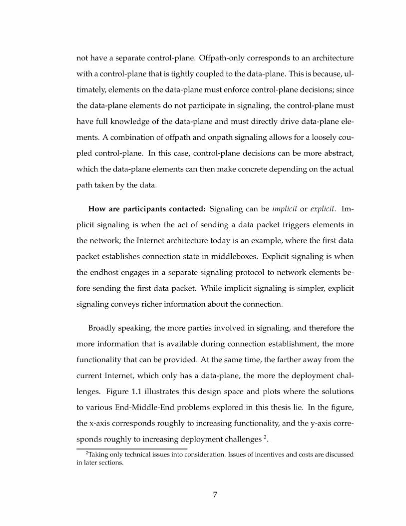
Broadly speaking, the more parties involved in signaling, and therefore the
more information that is available during connection establishment, the more
functionality that can be provided. At the same time, the farther away from the
current Internet, which only has a data-plane, the more the deployment chal-
lenges. Figure 1.1 illustrates this design space and plots where the solutions
to various End-Middle-End problems explored in this thesis lie. In the figure,
the x-axis corresponds roughly to increasing functionality, and the y-axis corre-
sponds roughly to increasing deployment challenges 2.
2Taking only technical issues into consideration. Issues of incentives and costs are discussedin later sections.
7
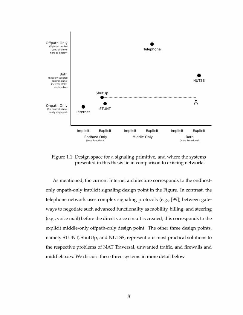
Figure 1.1: Design space for a signaling primitive, and where the systemspresented in this thesis lie in comparison to existing networks.
As mentioned, the current Internet architecture corresponds to the endhost-
only onpath-only implicit signaling design point in the Figure. In contrast, the
telephone network uses complex signaling protocols (e.g., [99]) between gate-
ways to negotiate such advanced functionality as mobility, billing, and steering
(e.g., voice mail) before the direct voice circuit is created; this corresponds to the
explicit middle-only offpath-only design point. The other three design points,
namely STUNT, ShutUp, and NUTSS, represent our most practical solutions to
the respective problems of NAT Traversal, unwanted traffic, and firewalls and
middleboxes. We discuss these three systems in more detail below.
8
1.2.1 STUNT: NAT Traversal
First, we tackle the problem of NAT Traversal. The problem arises from the
fundamental constraint of network address translation: multiple hosts behind a
NAT share the same (external) IP address. When a host behind the NAT initiates
a connection to an external host, the NAT creates state based on the connection
5-tuple (addresses, ports, protocol) that allows it to correctly route packets in
the reverse direction. If, however, the external host initiates the connection, the
NAT cannot disambiguate which internal host to route the connection to. When
two hosts behind their respective NATs wish to communicate, neither host can
successfully initiate the connection since each is external to the other’s NAT.
In Chapter 2, we present a comprehensive set of solutions to the NAT traver-
sal problem. In recent years, solutions have been developed for traversing NAT
boxes using UDP (that is, establishing UDP flows between hosts behind NATs).
The UDP solution relies on the connection-less nature of UDP to create NAT
state. Unlike UDP, however, TCP requires connection initiation packets to be
received and acknowledged by the destination before the connection is estab-
lished [89]. Since NATs prevent delivery of these packets, TCP NAT traversal
is more difficult. Indeed, TCP NAT traversal was considered impossible until
recently when we proposed our solution.
STUNT establishes TCP connections between hosts behind NATs without
any changes to existing NATs, or to existing endhost protocol stacks. We lever-
age the existing implicit signaling channel between the endhost and the NAT
(that is, the act of initiating a connection) simultaneously on both ends to create
the necessary state in both NATs. Explicit signaling between the two endpoints
is needed to synchronize the connection establishment attempt.
9
Since our original proposal, other researchers have proposed additional TCP
traversal approaches. The success of all these approaches depends on howNAT
boxes in the real-world respond to various sequences of TCP (and ICMP) pack-
ets. To settle this question, we perform the first broad study of NAT behavior
for a comprehensive set of TCP NAT traversal techniques over a wide range of
commercial NAT products. We develop a publicly available software test suite
for this purpose that measures the NAT responses both to a variety of isolated
probes and to complete TCP connection establishments. We test sixteen NAT
products in the lab, and 87 home NATs in the wild. Using these results, as well
as market data for NAT products, we estimate the likelihood of successful NAT
traversal for home networks. We find that NATs deployed on the Internet to-
day can be traversed successfully 85%–90% of the time using the techniques
presented in Chapter 2.
1.2.2 ShutUp: Reducing Unwanted Traffic
In Chapter 3, we take a fresh perspective on the problem of unwanted traffic
— DoS attacks and Internet worms. The majority of existing defense proposals
assume a purely in-network architecture, requiring changes to routers deployed
deep in the Internet core or requiring new infrastructure to be deployed at spe-
cific points in the network. We pose, and answer in the affirmative, the question
of whether a purely E2E architecture can solve DoS and worms. The challenge
in doing so is to design the simplest set of primitives and mechanisms that ad-
dress both classes of unwanted traffic within the same general framework.
We present the design of a “ShutUp Service”, whereby the recipient of DoS
10
traffic explicitly signals the sender to slow down or stop. Tamper-proof end-
host software, implemented for instance with trusted platforms and virtual ma-
chines, reacts to the signal by taking the appropriate action. The same basic
approach is used to slow down the spread of flash worms: non-vulnerable end-
hosts that a worm attempts to infect explicitly signal the sender to block address
or port scans performed by the worm.
As purely a deployment expedient, the design allows in-network elements
to play the same role for a group of endhosts. ShutUp requires only minimal
changes to the endhost, which can be achievedwith buy-in from a small number
of vendors, and requires no changes to Internet protocols or to the network. We
present a detailed security analysis and show through experimentation that the
service has little impact on legitimate traffic.
1.2.3 NUTSS: End-Middle-End Connection Establishment
In Chapter 4, we present the NUTSS architecture, protocol design, and imple-
mentation that satisfies the End-Middle-End requirements for connection es-
tablishment. NUTSS takes into account the combined policies of endpoints and
network providers. Specifically, NUTSS solves a wide range of problems on the
Internet, including access control, middlebox steering, multi-homing, mobility,
and protocol negotiation.
While NUTSS borrows liberally from other proposals (URI-like naming, sig-
naling to manage ephemeral IPv4 or IPv6 data flows), NUTSS is unique in
that it uses explicit offpath and onpath signaling, and couples the two using
lightweight mechanisms. As a result, NUTSS requires no changes to existing
11
network protocols, and combined with recent NAT traversal techniques, works
with IPv4 and existing NATs and firewalls. Overall, NUTSS represents an ar-
gument that advanced connection establishment functionality, and incremental
deployment are not mutually exclusive.
1.3 Evolving the Real-World Internet
Impact in the real world owes perhaps a small fraction to the research that went
into it, and the majority to the engineering effort. A discussion about evolving
the Internet without the engineering perspective is incomplete. In Chapter 5
we chronicle our efforts within the Internet Research Task Force (IRTF) and the
Internet Engineering Task Force (IETF) to bridge the gap between research and
practice.
We have succeeded in incorporating the lessons learned from STUNT into
the specifications of designing NATs [7, 45, 110], and in incorporating the
STUNT mechanism into the Session Traversal Utilities for NAT (STUN) and In-
teractive Connectivity Establishment (ICE) toolkits that application developers
can use to traverse NATs [98, 96]. With NUTSS, we experienced a more mixed
result within the End-Middle-End Research Group (EMERG) formed specifi-
cally to explore the architectural implications.
Finally, in Chapter 6, we conclude this thesis by reflecting on the challenges
in bridging the gap from research to practice that go largely unnoticed by the re-
search and engineering communities. Given the money at stake for companies
maintaining and extending the Internet, we believe a purely technical perspec-
tive on evolving the Internet is no longer sufficient. As researchers, we must rise
12

to the challenge of tackling not only the technological issues, but doing so in a
way that is aligned with the business interests of those who are in a position to
bring the research into practice.
13
CHAPTER 2
STUNT: RESTORING GLOBAL CONNECTIVITY THROUGH NATS
The Internet architecture today is vastly different from that envisioned when
TCP/IP was designed. Firewalls and Network address and port translators
(NATs) often make it impossible to establish a connection even if it does not
violate policy. NATs break the IP connectivity model by preventing hosts on
the external side of the NAT from initiating a connection with a host behind the
NAT since the external host cannot name the internal host using an IP address.
If both endpoints are behind their respective NAT, ordinary TCP cannot be es-
tablished since the end initiating the TCP is outside the other end’s NAT. The
problem is not specific to NATs; firewalls too have this problem, albeit because
firewalls unilaterally block packets. Even if the connection would be allowed
according to each end’s firewall security policy, for instance, if the firewall pol-
icy is that internal hosts may initiate TCP connections and both hosts wish to
initiate, still neither host’s packet is delivered to the other host as each host
is outside the other’s firewall. In Section 2.3 of this chapter, we present our
original set of workarounds that establish a TCP connection without the use of
proxies or tunnels, and review more recent proposals [24, 11, 28]. These ap-
proaches set up the necessary connection state on the NAT or firewall1 through
a carefully crafted exchange of TCP packets. However, because NAT behavior
is not standardized2, not all NATs in the wild react the same way, causing these
approaches to fail in various cases. Understanding such behavior in NATs and
1For the remainder of this chapter, the term NAT is understood to include firewalls.2At the time this research was conducted (early 2005), there existed no Internet RFC specify-
ing how NATs should behave. Indeed, the research presented in this chapter led directly to RFC5382 [45], which lays out the NAT Behavioral Requirements for TCP.
14
measuring how much they detract from the original goal of universal connec-
tivity in the Internet is crucial to integrating them cleanly into the architecture.
To illustrate the NAT problem, consider for instance Alice and Bob whowish
to communicate with each other. Both Alice and Bob disallow unsolicited con-
nections by hiding behind a NAT or by configuring their firewalls to drop in-
bound SYN packets. Yet when both Alice and Bob agree to establish a connec-
tion, there is no way to do so without reconfiguring their NAT since Alice’s
SYN is dropped by Bob’s NAT and vice versa. Even so, NATs and firewalls
have become a permanent part of the network infrastructure and will continue
to remain so for a long time. Even if IPv6 is deployed globally, IPv4-IPv6 NATs
will be needed during the lengthy transition, and IPv6 firewalls will be needed
for security. As a result, mechanisms that enable two consenting hosts behind
NATs to communicate with each other are needed.
This problem has been solved for UDP by STUN [100]. STUN leverages the
basic NAT translation mechanism [109]: NATsmaintain a mapping between the
internal IP address and port, and the external IP address and port allocated for
the first outbound packet of a flow; any packets to the external address and port
are translated and routed to the internal address and port. In STUN, Alice sends
a UDP packet to Bob. Although this packet is dropped by Bob’s NAT, it causes
Alice’s NAT to create local state that allows Bob’s response to be directed to Al-
ice. A third party that both Alice and Bob are in contact with informs Bob that
Alice attempted to contact him from her allocated external address and port.
Bob then sends a UDP packet to Alice. Alice’s NAT considers it part of the first
packet’s flow and routes it through, while Bob’s NAT considers it a connection
initiation and creates local state to route Alice’s responses. This approach is
15
used by Skype, a popular VoIP application [9]. Unfortunately, establishing TCP
is more complicated. Once Alice sends her SYN packet, her OS stack as well as
her NAT expect to receive a SYNACK packet from Bob in response. However,
since the SYN packet was dropped, Bob’s stack doesn’t generate the SYNACK.
Proposed workarounds to the problem [24, 11, 28] are complicated, their inter-
actions with NATs in the wild are poorly understood, and the extent to which
they solve the problem is not known. Consequently, applications such as the
file-transfer module in Skype, which require reliably in-order delivery that TCP
is designed to provide, reinvent the wheel by building on top of UDP. While
such approaches may work, we believe it is important that wherever possible,
applications use the native OS TCP stack. This is in part to avoid increasingly
complex protocol stacks, but more importantly because TCP stacks have, over
the years, been carefully optimized for high performance and congestion friend-
liness.
In summary, this chapter describes five contributions. First, it identifies and
describes the complete set of NAT characteristics important to TCP NAT traver-
sal. Second, it reports on the prevalence both of these individual characteristics
and of the success rate of peer-to-peer TCP connections for the various proposed
approaches. Third, based on these measurements, it suggests modifications to
the proposed approaches. Fourth, it provides insights for application develop-
ers into the implementation issues pertaining to NAT traversal. Additionally, it
describes a public-domain software toolkit that can be used to measure NATs
as they evolve, and can serve as the basis of TCP NAT traversal in P2P appli-
cations. Finally, the results presented in this chapter have been used to guide
the standardization process of NATs and firewalls, making them more traversal
friendly without circumventing security policies.
16

2.1 TCP NAT-Traversal
In this section we discuss the TCP NAT-traversal approaches that have been
proposed in recent literature. All approaches share certain elements in common:
First, in all the approaches, both ends initiate a TCP connection; this is neces-
sary since NAT state for TCP connections can only be created by an outbound
SYN packet. Second, each approach then reconciles the two TCP attempts into
a single connection through different mechanisms. The reconciliation mecha-
nism used triggers different behavior in different NATs causing the proposed
approaches to fail in many instances. Third, each approach must predict the
address and port the SYN will appear to come from so the other side can create
the correct NAT mapping. This is performed through port prediction. Port pre-
diction allows a host to guess the NATmapping for a connection before sending
the outbound SYN. Fourth, each approach also requires some coordination be-
tween the two hosts. This is accomplished over an out-of-band channel such as
a connection proxied by a third party or a UDP/STUN session. Once the direct
TCP connection is established, the out-of-band channel can be closed. Finally, it
is possible for either endpoint to be behind multiple NATs3. In such cases the
result of each approach depends on a composite of the behavior of all the NATs
and firewalls in the path. For brevity we overload the term ‘NAT’ to mean the
composite NAT/firewall.
17
SYN (low TTL)
SYNACK (spoofed)
ACK
ClientA
NATM
STUNTServer
NATN
ClientB
ICMP
TCP Seq#
SYN (low TTL)
ICMP
TCP Seq#
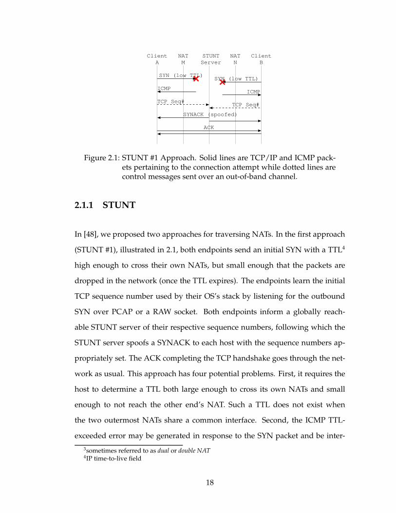
Figure 2.1: STUNT #1 Approach. Solid lines are TCP/IP and ICMP pack-ets pertaining to the connection attempt while dotted lines arecontrol messages sent over an out-of-band channel.
2.1.1 STUNT
In [48], we proposed two approaches for traversing NATs. In the first approach
(STUNT #1), illustrated in 2.1, both endpoints send an initial SYN with a TTL4
high enough to cross their own NATs, but small enough that the packets are
dropped in the network (once the TTL expires). The endpoints learn the initial
TCP sequence number used by their OS’s stack by listening for the outbound
SYN over PCAP or a RAW socket. Both endpoints inform a globally reach-
able STUNT server of their respective sequence numbers, following which the
STUNT server spoofs a SYNACK to each host with the sequence numbers ap-
propriately set. The ACK completing the TCP handshake goes through the net-
work as usual. This approach has four potential problems. First, it requires the
host to determine a TTL both large enough to cross its own NATs and small
enough to not reach the other end’s NAT. Such a TTL does not exist when
the two outermost NATs share a common interface. Second, the ICMP TTL-
exceeded error may be generated in response to the SYN packet and be inter-
3sometimes referred to as dual or double NAT4IP time-to-live field
18
SYN (low TTL)
ACK
ClientA
NATM
NATN
ClientB
ICMP
SYN
SYNACK
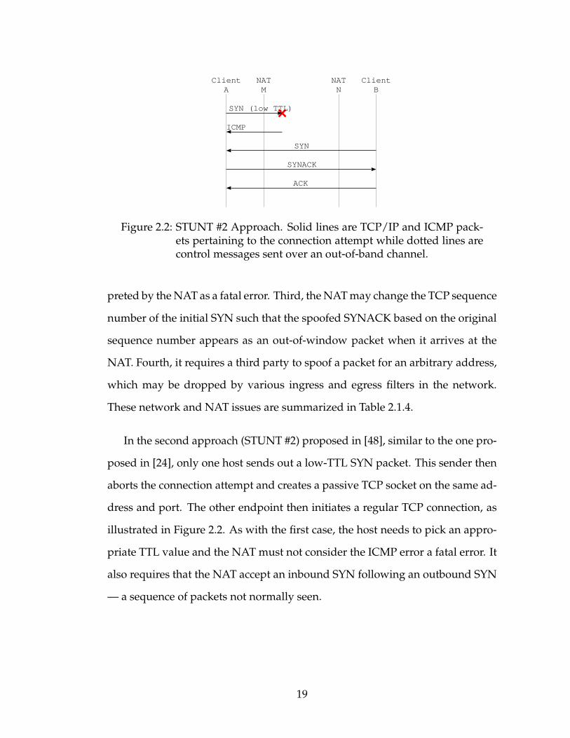
Figure 2.2: STUNT #2 Approach. Solid lines are TCP/IP and ICMP pack-ets pertaining to the connection attempt while dotted lines arecontrol messages sent over an out-of-band channel.
preted by theNAT as a fatal error. Third, theNATmay change the TCP sequence
number of the initial SYN such that the spoofed SYNACK based on the original
sequence number appears as an out-of-window packet when it arrives at the
NAT. Fourth, it requires a third party to spoof a packet for an arbitrary address,
which may be dropped by various ingress and egress filters in the network.
These network and NAT issues are summarized in Table 2.1.4.
In the second approach (STUNT #2) proposed in [48], similar to the one pro-
posed in [24], only one host sends out a low-TTL SYN packet. This sender then
aborts the connection attempt and creates a passive TCP socket on the same ad-
dress and port. The other endpoint then initiates a regular TCP connection, as
illustrated in Figure 2.2. As with the first case, the host needs to pick an appro-
priate TTL value and the NAT must not consider the ICMP error a fatal error. It
also requires that the NAT accept an inbound SYN following an outbound SYN
— a sequence of packets not normally seen.
19
SYN (low TTL)
SYNACK
ACK
ClientA
NATM
NATN
ClientB
ICMP
TCP Seq#
SYN (low TTL)
ICMP
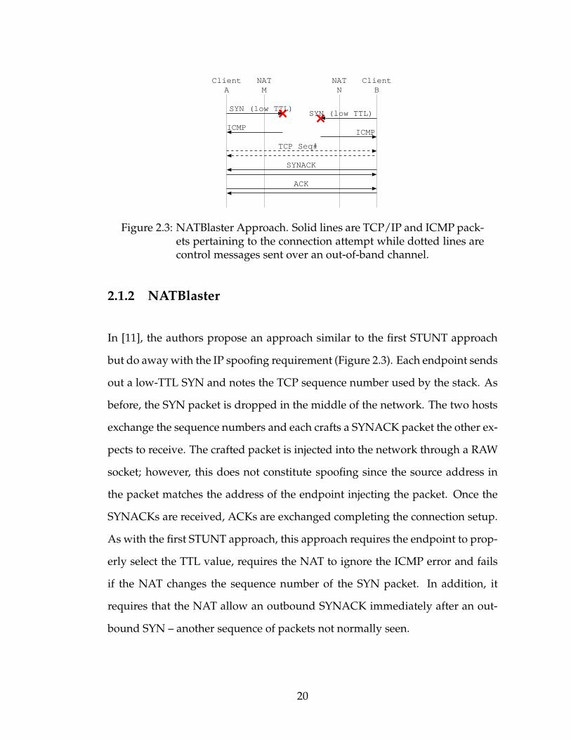
Figure 2.3: NATBlaster Approach. Solid lines are TCP/IP and ICMP pack-ets pertaining to the connection attempt while dotted lines arecontrol messages sent over an out-of-band channel.
2.1.2 NATBlaster
In [11], the authors propose an approach similar to the first STUNT approach
but do awaywith the IP spoofing requirement (Figure 2.3). Each endpoint sends
out a low-TTL SYN and notes the TCP sequence number used by the stack. As
before, the SYN packet is dropped in the middle of the network. The two hosts
exchange the sequence numbers and each crafts a SYNACK packet the other ex-
pects to receive. The crafted packet is injected into the network through a RAW
socket; however, this does not constitute spoofing since the source address in
the packet matches the address of the endpoint injecting the packet. Once the
SYNACKs are received, ACKs are exchanged completing the connection setup.
As with the first STUNT approach, this approach requires the endpoint to prop-
erly select the TTL value, requires the NAT to ignore the ICMP error and fails
if the NAT changes the sequence number of the SYN packet. In addition, it
requires that the NAT allow an outbound SYNACK immediately after an out-
bound SYN – another sequence of packets not normally seen.
20
SYN
SYNACK
ACK
ClientA
NATM
NATN
ClientB
SYN
Figure 2.4: P2PNAT Approach. Solid lines are TCP/IP and ICMP pack-ets pertaining to the connection attempt while dotted lines arecontrol messages sent over an out-of-band channel.
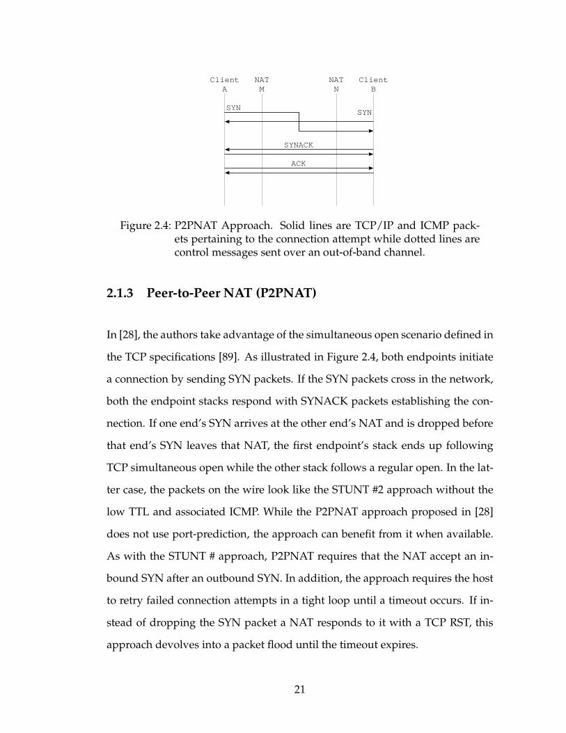
2.1.3 Peer-to-Peer NAT (P2PNAT)
In [28], the authors take advantage of the simultaneous open scenario defined in
the TCP specifications [89]. As illustrated in Figure 2.4, both endpoints initiate
a connection by sending SYN packets. If the SYN packets cross in the network,
both the endpoint stacks respond with SYNACK packets establishing the con-
nection. If one end’s SYN arrives at the other end’s NAT and is dropped before
that end’s SYN leaves that NAT, the first endpoint’s stack ends up following
TCP simultaneous open while the other stack follows a regular open. In the lat-
ter case, the packets on the wire look like the STUNT #2 approach without the
low TTL and associated ICMP. While the P2PNAT approach proposed in [28]
does not use port-prediction, the approach can benefit from it when available.
As with the STUNT # approach, P2PNAT requires that the NAT accept an in-
bound SYN after an outbound SYN. In addition, the approach requires the host
to retry failed connection attempts in a tight loop until a timeout occurs. If in-
stead of dropping the SYN packet a NAT responds to it with a TCP RST, this
approach devolves into a packet flood until the timeout expires.
21
2.1.4 Implementation
We implemented STUNT #1 and #2, NATBlaster, and P2PNAT on both Linux
and Windows. We also developed a Windows device driver that implements
the functionality required by the approaches that are not natively supported by
Windows. The STUNT # approach requires superuser privileges under both
Windows and Linux to overhear the TCP SYN packet on the wire and learn its
sequence number. In order to set the TTL on the first SYN packet, we use the
IP TTL socket option under Linux and our driver under Windows. We also im-
plemented the STUNT server and host it behind an ISP that does not perform
egress filtering in order to spoof arbitrary addresses. While the server was able
to spoof most SYNACKs, it was not successful in spoofing SYNACKs where
both the source and destination were in the same administrative domain and
the domain used ingress filtering. When possible, an additional STUNT server
is installed inside such domains. The STUNT #2 approach requires the driver
to set the TTL under Windows. The NATBlaster approach requires superuser
privileges to learn the sequence number of the SYN and to inject the crafted
SYNACK through a RAW socket. Due to a restriction introduced in Windows
XP SP2, the approach requires the driver to inject this packet. The P2PNAT ap-
proach requires the OS to support TCP simultaneous open; this is supported
under Linux and Windows XP SP2 but not by Windows XP prior to SP2. On
Windows XP SP1 and earlier, our driver adds support for this. These imple-
mentation issues are summarized in the top half of Table 2.1.4.
We found that setting the TTL is problematic under Windows; therefore, we
consider the consequences of not using it. If the TTL is not reduced, the first
SYN sent by one of the hosts reaches the other end’s NAT before that end’s SYN
22
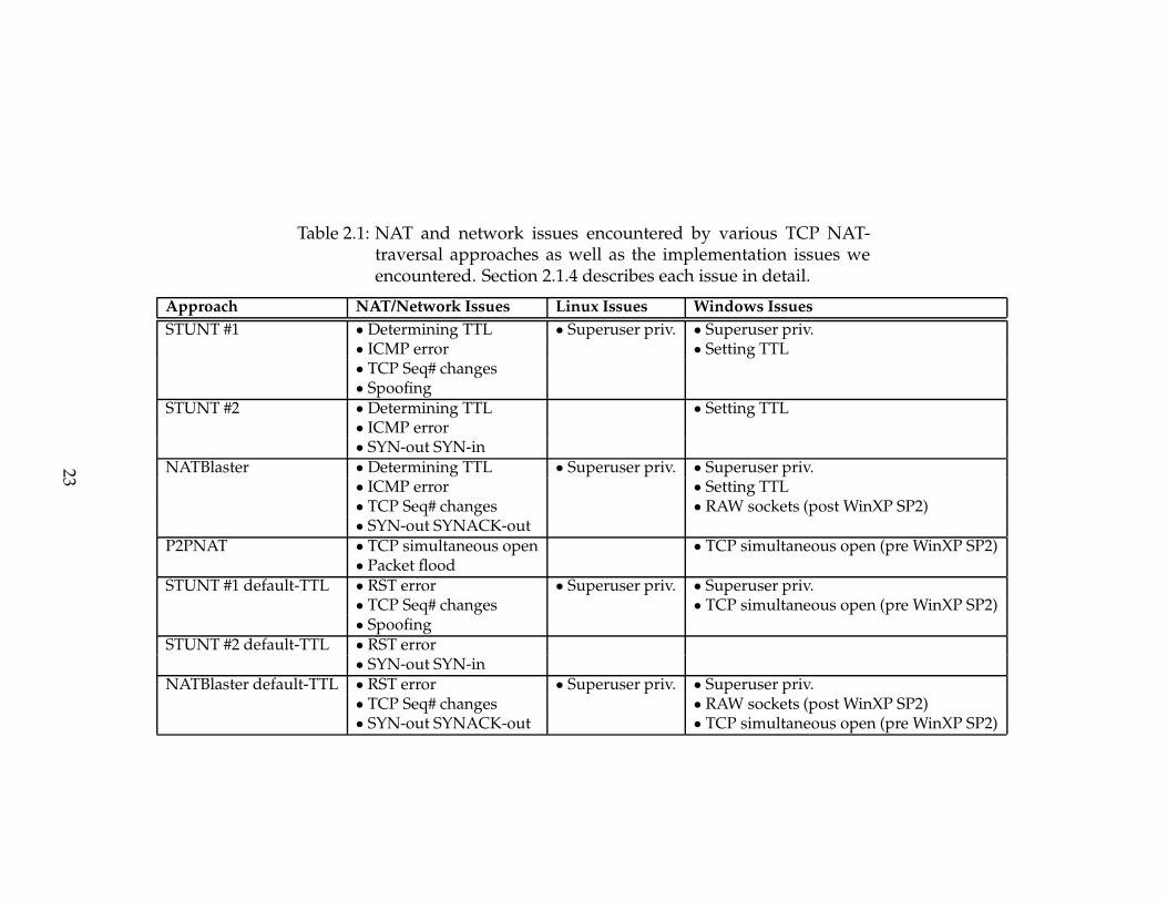
Table 2.1: NAT and network issues encountered by various TCP NAT-traversal approaches as well as the implementation issues weencountered. Section 2.1.4 describes each issue in detail.
Approach NAT/Network Issues Linux Issues Windows Issues
STUNT #1 • Determining TTL • Superuser priv. • Superuser priv.• ICMP error • Setting TTL• TCP Seq# changes• Spoofing
STUNT #2 • Determining TTL • Setting TTL• ICMP error• SYN-out SYN-in
NATBlaster • Determining TTL • Superuser priv. • Superuser priv.• ICMP error • Setting TTL• TCP Seq# changes • RAW sockets (post WinXP SP2)• SYN-out SYNACK-out
P2PNAT • TCP simultaneous open • TCP simultaneous open (pre WinXP SP2)• Packet flood
STUNT #1 default-TTL • RST error • Superuser priv. • Superuser priv.• TCP Seq# changes • TCP simultaneous open (pre WinXP SP2)• Spoofing
STUNT #2 default-TTL • RST error• SYN-out SYN-in
NATBlaster default-TTL • RST error • Superuser priv. • Superuser priv.• TCP Seq# changes • RAW sockets (post WinXP SP2)• SYN-out SYNACK-out • TCP simultaneous open (pre WinXP SP2)
23

exits the same NAT. The NAT can either silently drop the inbound packet, or
respond with an ICMP unreachable error or a TCP RST/ACK. The response, if
any, may trigger transitions in the sender’s NAT and OS stack unaccounted for
by the approach. If the TTL for the other end’s SYN packet is not reduced either,
the SYN may reach the intended destination triggering unforeseen transitions.
The behavior may be favorable to the ultimate goal if, for instance, it triggers a
TCP simultaneous-open, or it may be detrimental if it confuses the stack or NAT.
To test the outcome of not lowering the TTL, we implement modified versions
of the above approaches that use the default TTLs set by the operating system.
Issues encountered are summarized in the bottom half of Table 2.1.4.
The astute reader will have noticed that the detailed description promised
for each issue in Table 2.1.4 has been omitted from this section. This is inten-
tional. We encourage the reader to contact the author for these details and a
small reward.
2.2 Experiment Setup
We have defined the STUNT client-server protocol that both tests NAT/firewall
behavior and assists in establishing TCP connections between NATed peers. A
complete protocol description is available in [43]. The protocol is implemented
by our test applications comprising of a client component and server compo-
nent. As shown in Figure 2.5, the client is run on a host behind one or more
NATs while the server is external to all of them. The STUNT test client detects
the composite behavior of all the NATs and firewalls between the client and the
server. While both the test client and server require superuser privileges to an-
24

Client
Personalfirewall
App.Wireless
Gateway/NATISP
NAT/firewall
Server Internet
Figure 2.5: A possible experiment setup for STUNT. Client component isbehind multiple NATs and the server component is outside allof them. The behavior determined by STUNT is the compositeof the individual NAT behaviors.
alyze raw packets on the wire, the requirement can be dropped for the client
in exchange for a small loss in functionality. The server, in addition, requires
at least two network interfaces to properly differentiate between various NAT
port allocation algorithms in use. The tests performed by the client and the NAT
characteristics inferred from them are described later in Section 2.3.
We used the client to test a diverse set of sixteen NATs in the lab (Table 2.2).
These include one of each brand of NAT that we could find in online stores in
the United States. The NATs tested also include software NAT implementations
in popular operating systems. In each lab test, the client host was the only host
internal to the NAT. To measure the latency introduced by the approaches, the
server was located on the same Ethernet segment as the external interface of
that NAT. The client host was set to not generate any network traffic other than
that caused by the test client.
In addition to these lab tests, we also tested NAT boxes in the wild. Themain
reason for this was to expose our test software to a wider range of scenarios than
25
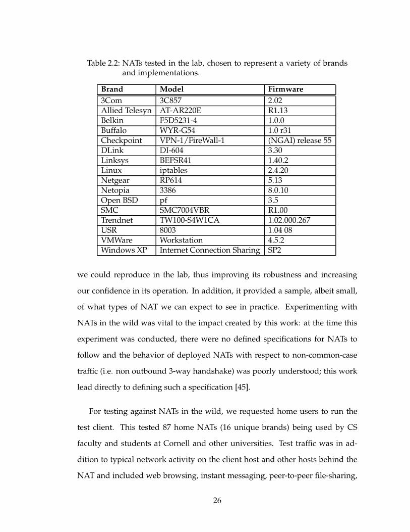
Table 2.2: NATs tested in the lab, chosen to represent a variety of brandsand implementations.
Brand Model Firmware
3Com 3C857 2.02Allied Telesyn AT-AR220E R1.13Belkin F5D5231-4 1.0.0Buffalo WYR-G54 1.0 r31Checkpoint VPN-1/FireWall-1 (NGAI) release 55DLink DI-604 3.30Linksys BEFSR41 1.40.2Linux iptables 2.4.20Netgear RP614 5.13Netopia 3386 8.0.10Open BSD pf 3.5SMC SMC7004VBR R1.00Trendnet TW100-S4W1CA 1.02.000.267USR 8003 1.04 08VMWare Workstation 4.5.2Windows XP Internet Connection Sharing SP2
we could reproduce in the lab, thus improving its robustness and increasing
our confidence in its operation. In addition, it provided a sample, albeit small,
of what types of NAT we can expect to see in practice. Experimenting with
NATs in the wild was vital to the impact created by this work: at the time this
experiment was conducted, there were no defined specifications for NATs to
follow and the behavior of deployed NATs with respect to non-common-case
traffic (i.e. non outbound 3-way handshake) was poorly understood; this work
lead directly to defining such a specification [45].
For testing against NATs in the wild, we requested home users to run the
test client. This tested 87 home NATs (16 unique brands) being used by CS
faculty and students at Cornell and other universities. Test traffic was in ad-
dition to typical network activity on the client host and other hosts behind the
NAT and included web browsing, instant messaging, peer-to-peer file-sharing,
26

Table 2.3: Observed market share of NAT brands in our sample set andworldwide SOHO/HomeWLANmarket share of each brand inQ1 2005 according to Synergy Research Group
MarketBrand Sample Survey
Linksys 24.1% 28.8%D-Link 9.2% 20.2%Netgear 6.9% 14.7%Buffalo Technologies 1.1% 10.9%Belkin 9.2% 4.6%Other 49.4% 20.9%
email, etc. The resulting data draws from a mix of NAT brands with both
new and old models and firmware; however, it admits a bias in the selection
of NATs given the relatively small user base with most of them living in the
north-eastern United States. This discrepancy is evident in Table 2.2, where the
observed popularity of brands in our sample is listed under ‘Sample’ and the
worldwide SOHO/HomeWLANmarket share of the brands in the first quarter
of 2005 as per the Synergy Research Group [120] is listed under ‘Market Survey’.
In particular, Buffalo Technologies and Netgear were under-represented in our
sample and the percentage of other brands was significantly higher. The full list
of home NATs tested is available in [44].
2.3 NAT TCP Characteristics
In this section, we identify how different NATs affect TCP NAT-traversal ap-
proaches. We identify five classifications for NAT behavior; namely, NAT map-
ping, endpoint packet filtering, filtering response, TCP sequence number pre-
serving and TCP timers. The classifications and the possible values that a NAT
27
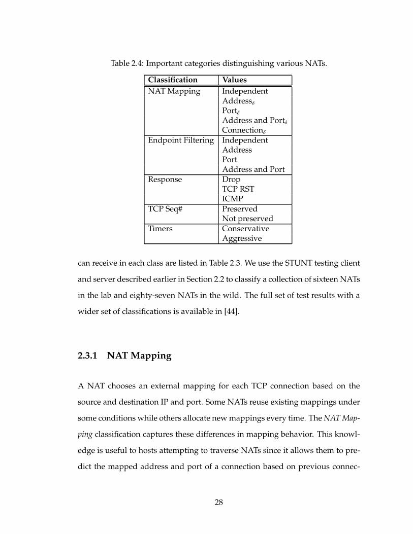
Table 2.4: Important categories distinguishing various NATs.
Classification Values
NATMapping IndependentAddressδPortδAddress and PortδConnectionδ
Endpoint Filtering IndependentAddressPortAddress and Port
Response DropTCP RSTICMP
TCP Seq# PreservedNot preserved
Timers ConservativeAggressive
can receive in each class are listed in Table 2.3. We use the STUNT testing client
and server described earlier in Section 2.2 to classify a collection of sixteen NATs
in the lab and eighty-seven NATs in the wild. The full set of test results with a
wider set of classifications is available in [44].
2.3.1 NATMapping
A NAT chooses an external mapping for each TCP connection based on the
source and destination IP and port. Some NATs reuse existing mappings under
some conditions while others allocate newmappings every time. TheNATMap-
ping classification captures these differences in mapping behavior. This knowl-
edge is useful to hosts attempting to traverse NATs since it allows them to pre-
dict the mapped address and port of a connection based on previous connec-
28

Table 2.5: NAT Mapping test behavior observed. Nat1–5 show the 5 dif-ferent mapping patterns that are observed in practice. Nat6 isa possible mapping pattern that has not been observed in oursample set.
# From To Nat1 Nat2 Nat3 Nat4 Nat5 Nat6
1 a:p B:Q A:P A:P A:P A:P1 A:P A:P2 a:p B:Q A:P A:P A:P+1 A:P2 A:P A:P3 a:p B:Q A:P A:P A:P+2 A:P3 A:P A:P4 a:p B:R A:P A:P+1 A:P+3 A:P4 A:P+1 A:P5 a:p B:R A:P A:P+1 A:P+4 A:P5 A:P+1 A:P6 a:p B:R A:P A:P+1 A:P+5 A:P6 A:P+1 A:P7 a:p C:R A:P A:P+2 A:P+6 A:P7 A:P+1 A:P+18 a:p C:R A:P A:P+2 A:P+7 A:P8 A:P+1 A:P+19 a:p C:R A:P A:P+2 A:P+8 A:P9 A:P+1 A:P+1
10 a:p C:Q A:P A:P+3 A:P+9 A:P10 A:P A:P+111 a:p C:Q A:P A:P+3 A:P+10 A:P11 A:P A:P+112 a:p C:Q A:P A:P+3 A:P+11 A:P12 A:P A:P+113 a:s B:Q A:S A:S A:S A:S1 A:S A:S
...
Classification NB: NB:Address NB: NB: NB: NB:Independent and Port1 Connection1 Connectionℜ Port1 Address1
29
Client
NAT
Server
Server
a:p
B:Q
B:R
C:R
C:Q
A:P
??
?
?
?
???
?
?
?
TCPConnections
#1
#12port
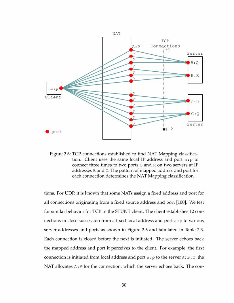
Figure 2.6: TCP connections established to find NAT Mapping classifica-tion. Client uses the same local IP address and port a:p toconnect three times to two ports Q and R on two servers at IPaddresses B and C. The pattern of mapped address and port foreach connection determines the NATMapping classification.
tions. For UDP, it is known that some NATs assign a fixed address and port for
all connections originating from a fixed source address and port [100]. We test
for similar behavior for TCP in the STUNT client. The client establishes 12 con-
nections in close succession from a fixed local address and port a:p to various
server addresses and ports as shown in Figure 2.6 and tabulated in Table 2.3.
Each connection is closed before the next is initiated. The server echoes back
the mapped address and port it perceives to the client. For example, the first
connection is initiated from local address and port a:p to the server at B:Q; the
NAT allocates A:P for the connection, which the server echoes back. The con-
30
nection is closed, and a second connection is initiated from the same local port
to the same server port; four out of the six types on NATs (Nat1–2,Nat5–6) reuse
the A:P allocation, while Nat3 allocates a new external port A:P+1 and Nat4
allocates a random other port (A:P2). The third connection once again contacts
the server at B:Q, the fourth connection contacts the server at a different port
(B:R), and so on. The test is repeated multiple times for different choices of the
local port (e.g. row 13).
We notice several distinct patterns among the mapped ports shown as Nat1–
Nat6 in Table 2.3. Let the mapping allocated for the first connection be called
A:P for each NAT. Nat1 reuses this mapping as long as the client source ad-
dress and port of a new connection matches that of the first connection. We
classify this behavior as NB:Independent since the mapping is determined only
by the source address and port and is independent of the destination address
and port. This is equivalent to cone behavior in [100] extended to include TCP.
Nat2 reuses the mapping only if both the source and destination address and
port for the new connection match the first connection. Such NATs are classi-
fied NB:Address and Port1 since both the destination address and port affect the
mapping. The subscript ‘1’ signifies that the difference between new mappings,
denoted by δ, is 1. [113] shows that for UDP, δ is fixed for many NATs and is
usually 1 or 2. We find that the same holds for TCP as well. All of the NATs
we encountered, however, have δ = 1. Nat3 allocates a new mapping for each
new connection, however, each new mapping has port δ = 1 higher than the
previous port. We classify Nat3 as NB:Connection1. Nat4, like Nat3, allocates a
new mapping for each TCP connection but there is no discernable pattern be-
tween subsequent mappings. We classify such NATs NB:Connectionℜ where the
subscript ‘ℜ’ indicates a random δ. Nat5 is a variation of Nat2 where the map-
31

Table 2.6: NATmapping types observed in a set of 16 NATs in the lab, andthat estimated for NATs in the wild based on our sampling of81 home NATs and worldwide market shares.
NATMapping Lab Wild
NB:Independent 9 70.7%NB:Address and Port1 3 23.1%NB:Connection1 3 3.6%NB:Port1 0 2.2%NB:Addressδ 0 0.0%NB:Connectionℜ 1 0.5%
ping is reused if the destination port matches in addition to the source address
and port. Nat6 is similar except the destination address needs to match instead
of the port. Together Nat5 and Nat6 are classified NB:Port1 and NB:Address1
respectively. NATs 2–6 display symmetric behavior as per [100].
Table 2.3.1 shows the relative proportion of each type of NAT. Column 2
shows the number of NATs from our testbed of sixteen NATs that were classi-
fied as a particular type. A majority of them are NB:Independent. The only one
that is NB:Connectionℜ is the NAT implementation in OpenBSD’s pf utility. We
also noticed that our Netgear RP614NATwith firmware 5.13 is NB:Connection1,
however, more recent Netgear NATs such as MR814V2 with firmware 5.3 05 are
NB:Independent. Column 3 estimates the behavior of NATs in the wild. The es-
timates are computed by taking the proportion of each type and brand of NAT
from eighty-one home NATs sampled and scaling them with a correction fac-
tor chosen to overcome the bias in our sample. The correction factor for each
brand is the ratio between the surveyed and observed market shares presented
in Table 2.2. The factor serves to increase the contribution of under-represented
brands in the estimated result and decrease the contribution of over-represented
brands. While our estimates are indicative of the general trend to the best of
32
?
?
a:p A:P B:Q B:W C:W
SYN
SYN
TCP 3-Way Handshake
1
3
Client NAT ServerC:Q
?
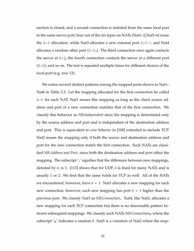
SYN2
Figure 2.7: TCP packets exchanged for Endpoint Filtering test. Client es-tablishes a connection to B:Q. Packet (1) is an inbound SYNfrom a different address and port (C:W), (2) from the same ad-dress but different port (B:W) and (3) from the same port butdifferent address (C:Q). The response to each of these deter-mines the Endpoint Filtering classification.
our knowledge, we note that in an industry changing at the rate of 47% per
year [120] the accuracy of any results is short lived at best. Nevertheless, we
estimate a majority of the NATs (70.7%) to be NB:Independent and almost none
to be NB:Connectionℜ. A significant percent (29.3%) of NATs have symmetric
behavior as defined in [100]. Consequently in a large fraction of cases, multiple
connections from the same port will not be assigned the same mapping and ap-
plications must employ the more sophisticated port-prediction techniques de-
scribed later.
2.3.2 Endpoint Filtering
Both NATs and firewalls may filter inbound packets addressed to a port unless
certain conditions are met. If no NAT mapping exists at that port, a NAT is
forced to filter the packet since it cannot forward it. If a mapping exists, how-
33

Table 2.7: NAT endpoint filtering behavior observed. Nat1′–Nat4′ show 4different filtering behaviors that are observed for inbound SYNpackets after an internal host establishes a connection from a:pto B:Qwith allocated mapping A:P.
# From To Nat1′ Nat2′ Nat3′ Nat4′
1 C:W A:P accepted filtered filtered filtered2 B:W A:P accepted filtered accepted filtered3 C:Q A:P accepted filtered filtered acceptedClassification EF:Independent EF:Address EF:Address EF:Port
and Port
ever, or if it the device is a firewall, then it may require that the source address
and/or port of the inbound packet match the destination of a preceding out-
bound packet. These differences in conditions that trigger filtering are captured
by the Endpoint Filtering classification. The STUNT test client determines this
by first establishing NAT state by connecting to the server. It then requests the
server to initiate connections to the mapped address and port from different
addresses and ports as shown in Figure 2.7.
The different filtering behaviors observed for the test are tabulated in Ta-
ble 2.3.2. Nat1′ accepts all three SYN packets. Such NATs allow inbound TCP
connections independent of the source address and port as long as necessary
state exists for routing the request. We classify such NATs as having the end-
point filtering behavior EF:Independent. Nat2′ filters all the packets thus requir-
ing the source of the inbound TCP packet match both the address and port of
the destination of the connection that created the mapping. The endpoint fil-
tering of such NATs is classified EF:Address and Port. Nat3′ and Nat4′ allow in-
bound packets from the same address or port as the destination address of the
connection but filter packets from a different address or port respectively. We
classify the endpoint filtering behavior of such NATs as EF:Address and EF:Port
34
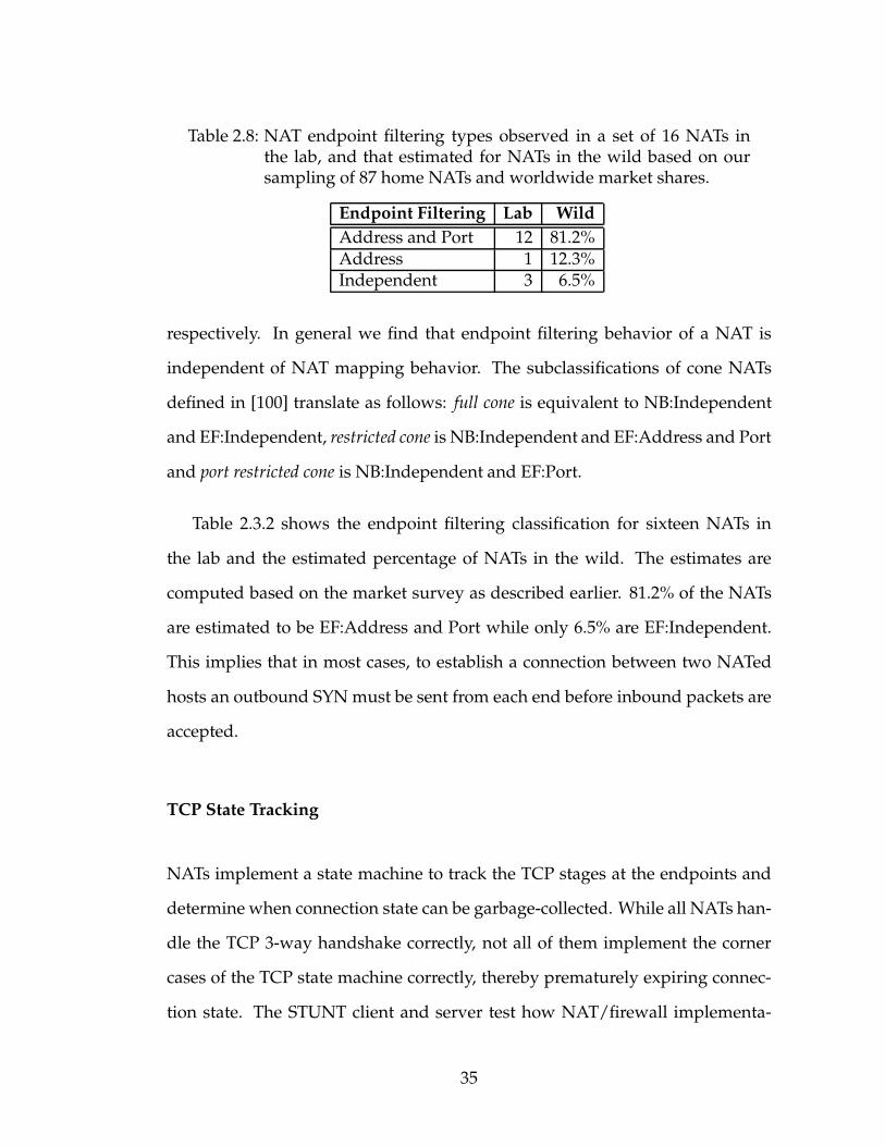
Table 2.8: NAT endpoint filtering types observed in a set of 16 NATs inthe lab, and that estimated for NATs in the wild based on oursampling of 87 home NATs and worldwide market shares.
Endpoint Filtering Lab Wild
Address and Port 12 81.2%Address 1 12.3%Independent 3 6.5%
respectively. In general we find that endpoint filtering behavior of a NAT is
independent of NAT mapping behavior. The subclassifications of cone NATs
defined in [100] translate as follows: full cone is equivalent to NB:Independent
and EF:Independent, restricted cone is NB:Independent and EF:Address and Port
and port restricted cone is NB:Independent and EF:Port.
Table 2.3.2 shows the endpoint filtering classification for sixteen NATs in
the lab and the estimated percentage of NATs in the wild. The estimates are
computed based on the market survey as described earlier. 81.2% of the NATs
are estimated to be EF:Address and Port while only 6.5% are EF:Independent.
This implies that in most cases, to establish a connection between two NATed
hosts an outbound SYN must be sent from each end before inbound packets are
accepted.
TCP State Tracking
NATs implement a state machine to track the TCP stages at the endpoints and
determine when connection state can be garbage-collected. While all NATs han-
dle the TCP 3-way handshake correctly, not all of them implement the corner
cases of the TCP state machine correctly, thereby prematurely expiring connec-
tion state. The STUNT client and server test how NAT/firewall implementa-
35

Table 2.9: Percentage of NATs not accepting various packet sequences. In-bound packets (-in) are in response to preceding outbound pack-ets (-out). ICMP code used is TTL-exceeded (non-fatal error).
Sequence Filtered
SYN-out SYNACK-in 0%SYN-out SYN-in 13.4%SYN-out ICMP-in SYNACK-in 7.0%SYN-out ICMP-in SYN-in 22.7%SYN-out RST-in SYNACK-in 19.8%SYN-out RST-in SYN-in 27.8%
tions affect TCP NAT-traversal approaches by replaying the packet sequences
observed for these approaches.
Table 2.3.2 lists some of the packet sequences tested. We estimate that
13.4% of NATs do not support TCP simultaneous open where an outbound SYN
is followed by an inbound SYN. This affects the P2PNAT approach, which re-
quires at least one end support simultaneous open as well as the second STUNT
approach. 7.0% filter inbound SYNACK packets after a transient ICMP TTL-
exceeded error. A similar number of NATs drop the inbound SYN packet after
the ICMP but accept it in the absence of the error. This behavior affects all the
approaches that set low TTLs on SYN packets. A fair number of NATs (27.8%)
accept inbound SYN packets even after the SYN packet that created the connec-
tion state is met with a fatal TCP RST. This mitigates the issue of spurious RSTs
that some approaches contend with. Not mentioned in the table is the sequence
SYN-out SYNACK-out that is required for the NATBlaster approach. We did
not test this case widely due to restrictions introduced by Windows XP SP2. In
the lab, however, we found that the D-Link NAT (DI-604) does not support it.
36

Filtering Response
When an inbound packet is filtered by a NAT it can choose to either drop the
packet silently or notify the sender. An estimated 91.7% of the NATs simply
drop the packet without any notification. The remaining NATs signal an error
by sending back a TCP RST acknowledgment for the offending packet.
2.3.3 Packet Mangling
NATs change the source address and port of outbound packets and the desti-
nation address and port of inbound packets. In addition, they need to translate
the address and port of encapsulated packets inside ICMP payloads so hosts can
match ICMPs to their respective transport sockets. All the NATs in our sample
set either perform the ICMP translation correctly or filter the ICMP packets,
which are not always generated in the first place. Some NATs change the TCP
sequence numbers by adding a constant per-flow offset to the sequence num-
ber of outbound packets and subtracting the same from the acknowledgment
number of inbound packets. We estimate that 8.8% of NATs change the TCP Se-
quence Number. Consequently in some cases, TCP NAT-traversal approaches
that require the initial sequence number of the packet leaving the NAT cannot
use the sequence number of the SYN at the end host in its stead.
2.3.4 TCP Timers
NATs and firewalls cannot indefinitely hold state since it makes them vulnerable
to DoS attacks. Instead they expire idle connections and delete connection state
37
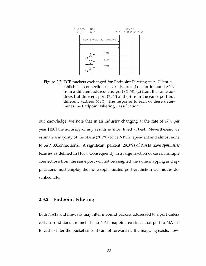
a:p A:PClient NAT
SYN
SYNACK
ACK
ACK
FIN
FIN/ACK
ACK
1 minute
2 hours
1 minute 1
2
3
ServerB:Q
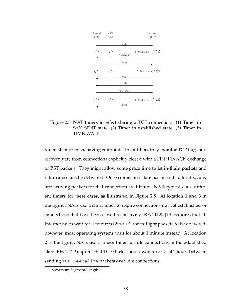
Figure 2.8: NAT timers in effect during a TCP connection. (1) Timer inSYN SENT state, (2) Timer in established state, (3) Timer inTIME WAIT.
for crashed or misbehaving endpoints. In addition, they monitor TCP flags and
recover state from connections explicitly closed with a FIN/FINACK exchange
or RST packets. They might allow some grace time to let in-flight packets and
retransmissions be delivered. Once connection state has been de-allocated, any
late-arriving packets for that connection are filtered. NATs typically use differ-
ent timers for these cases, as illustrated in Figure 2.8. At location 1 and 3 in
the figure, NATs use a short timer to expire connections not yet established or
connections that have been closed respectively. RFC 1122 [13] requires that all
Internet hosts wait for 4 minutes (2×MSL5) for in-flight packets to be delivered;
however, most operating systems wait for about 1 minute instead. At location
2 in the figure, NATs use a longer timer for idle connections in the established
state. RFC 1122 requires that TCP stacks should wait for at least 2 hours between
sending TCP-Keepalive packets over idle connections.
5Maximum Segment Length
38
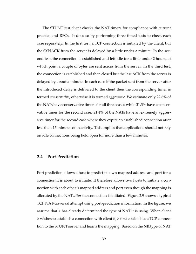
The STUNT test client checks the NAT timers for compliance with current
practice and RFCs. It does so by performing three timed tests to check each
case separately. In the first test, a TCP connection is initiated by the client, but
the SYNACK from the server is delayed by a little under a minute. In the sec-
ond test, the connection is established and left idle for a little under 2 hours, at
which point a couple of bytes are sent across from the server. In the third test,
the connection is established and then closed but the last ACK from the server is
delayed by about a minute. In each case if the packet sent from the server after
the introduced delay is delivered to the client then the corresponding timer is
termed conservative, otherwise it is termed aggressive. We estimate only 22.6% of
the NATs have conservative timers for all three cases while 31.3% have a conser-
vative timer for the second case. 21.4% of the NATs have an extremely aggres-
sive timer for the second case where they expire an established connection after
less than 15 minutes of inactivity. This implies that applications should not rely
on idle connections being held open for more than a few minutes.
2.4 Port Prediction
Port prediction allows a host to predict its own mapped address and port for a
connection it is about to initiate. It therefore allows two hosts to initiate a con-
nection with each other’s mapped address and port even though themapping is
allocated by the NAT after the connection is initiated. Figure 2.9 shows a typical
TCP NAT-traversal attempt using port-prediction information. In the figure, we
assume that A has already determined the type of NAT it is using. When client
Awishes to establish a connection with client B, A first establishes a TCP connec-
tion to the STUNT server and learns the mapping. Based on the NB:type of NAT
39
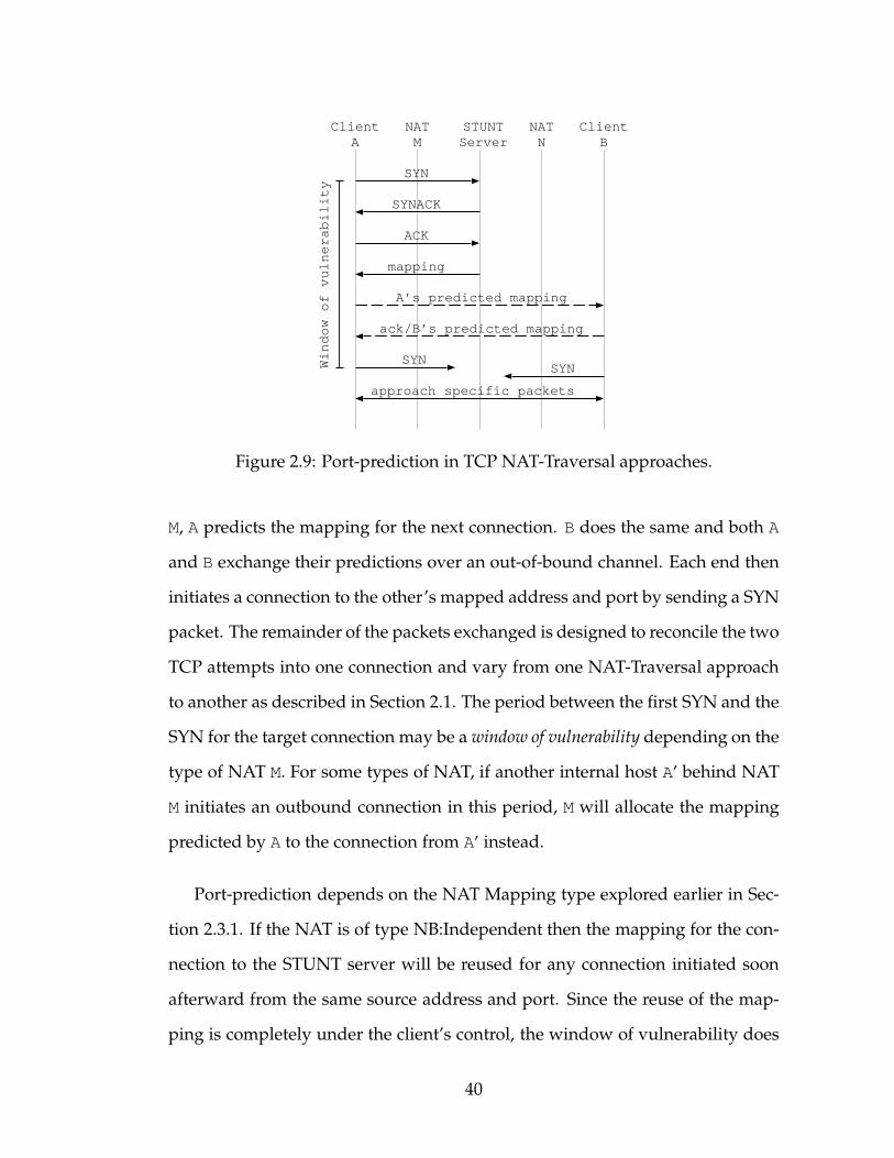
SYN
SYNACK
ACK
mapping
A’s predicted mapping
ack/B’s predicted mapping
SYNWindow of vulnerability
ClientA
NATM
STUNTServer
NATN
ClientB
approach specific packets
SYN
Figure 2.9: Port-prediction in TCP NAT-Traversal approaches.
M, A predicts the mapping for the next connection. B does the same and both A
and B exchange their predictions over an out-of-bound channel. Each end then
initiates a connection to the other’s mapped address and port by sending a SYN
packet. The remainder of the packets exchanged is designed to reconcile the two
TCP attempts into one connection and vary from one NAT-Traversal approach
to another as described in Section 2.1. The period between the first SYN and the
SYN for the target connection may be a window of vulnerability depending on the
type of NAT M. For some types of NAT, if another internal host A′ behind NAT
M initiates an outbound connection in this period, M will allocate the mapping
predicted by A to the connection from A′ instead.
Port-prediction depends on the NAT Mapping type explored earlier in Sec-
tion 2.3.1. If the NAT is of type NB:Independent then the mapping for the con-
nection to the STUNT server will be reused for any connection initiated soon
afterward from the same source address and port. Since the reuse of the map-
ping is completely under the client’s control, the window of vulnerability does
40

not exist in this case. However, this approach introduces a latency of 2×RTT6
to the STUNT server before the mapping can be predicted. For a possible op-
timization, we noticed that a number of NATs usually allocate a mapped port
equal to the source port used by the client. We term these NATs port preserving.
Clients behind such a NAT can, with high probability, predict the mapped port
without first establishing a connection to the STUNT server. If the NAT is not
NB:Independent but has a fixed δ then a connection initiated immediately after
the server connection will have a mapped port δ higher than the mapped port
observed by the server. Since the mapping changes from connection to connec-
tion, a “rogue” connection attempt in the window of vulnerability can steal the
mapping. In addition, this approach fails if the predicted mapping is already in
use, causing the NATs allocation routine to skip over it.
We implemented port-prediction in the STUNT test client and predicted
mappings for seventy-nine home users for an hour. Every minute, the test client
initiates a connection to the STUNT server from a source address and port and
learns the mapping allocated. Next it uses the same source address and port to
initiate a connection to a remote host setup for the purpose of this experiment.
The test client checks the mapping actually observed for the second connec-
tion against the one predicted based on the mapping for the first and type of
NAT. Port-prediction is successful if and only if they match. The predictions
are performed while users use their host and network normally. This includes
web browsers, email readers, instant messaging and file-sharing applications
running on the client host and other hosts behind the same NAT. 89.8% of the
NB:Independent NATs are port preserving. This represents a big win for in-
teractive applications that implement the optimization above. We find that in
6Round-trip time
41
82.3% of the cases the port was predicted correctly every time. This includes
all but one of the NB:Independent NATs and 36.4% of the non-NB:Independent
NATs. For the remaining 63.6% of the latter variety, at least one time out of the
sixty another host or application stole the mapping the test client predicted for
itself. In one particular case, the client host behind a NB:Connection1 NAT was
infected with a virus that generated several randomly-addressed SYN packets
per second causing all predictions to fail! In another case, the user initiated a
VPN connection midway through the test causing all subsequent requests to be
sent over the VPN and thus through a different type of NAT. This suggests that
long-running applications may cache the NATmapping type for some time but
must revalidate it from time to time. Overall, in 93.7% of the cases, more than
three-fourths of the port-predictions were correct. Hence after a failed attempt
if an application simply retries the connection, it is likely to succeed.
2.4.1 Effect of Port-Prediction Vulnerability Window
Outbound connections initiated by other applications or internal hosts during
the window of vulnerability can foil a port-prediction attempt. This window
of vulnerability lasts for about 3×RTT as illustrated in Figure 2.9. In [133],
the authors measure RTTs for 16 million host-pairs and find that under nor-
mal network operation the maximum RTT is 1 second (250ms in the median
case). Given this, we try to answer the question: what is the likelihood that a
port-prediction attempt will fail due to another interfering connection attempt.
We first try to understand how typical hosts initiate connections. We traced
TCP SYN packets from 641 hosts in the Cornell CS Department to hosts outside
42

0
10
20
30
40
50
60
70
80
90
100
0 10 20 30 40 50 60
% o
f Bur
sts
Time (seconds)
Burst LengthInter-Burst Interval
Figure 2.10: CDF of length and inter-arrival time of bursts.
for 33 days for a total of 13.6 million TCP connections. The hosts traced included
hosts used by faculty, staff and students as their primary terminals, data acqui-
sition and compute clusters but not webservers, mail servers and other hosts
placed in the DMZ. The trace was collected at the department’s firewall that
only allows outbound connections. We find that the arrival of new connections
is bursty in accordance with the observations made in [25]. Hosts established
about 820 connections per day on average but 88.8% of the connections were
initiated within 5 seconds of another connection from the same host. This is be-
cause a large fraction of the connections are HTTP requests where the browsers
download a website and then initiate additional connections to same or other
servers for content embedded in the webpage.
43

We clustered these connections into bursts where a sequence of connections
from a host with at most 5 seconds between connections is clustered together.
This resulted in 1.52 million bursts. For each burst, we define the length of the
burst as the time between the first and last connection in that burst. The inter-
burst interval of two sequential bursts for the same host is defined as the time
between the last connection of the first burst and the first connection of the sec-
ond burst. Figure 2.10 shows the CDF of burst lengths and inter-burst intervals
observed. 61.0% of the bursts have a length less than 1 second while 95% of
bursts have length less than 14 seconds. The median inter-burst interval, on
the other hand, is 26 seconds. Together this suggests that if a port-prediction
attempt is made, it is more likely to fall in the gap of inactivity between two
bursts and therefore succeed.
To quantify the how often port-prediction attempts will be interrupted by
rogue connection attempts, multiple active hosts behind the same NAT need
to be modeled. The type of the NAT is irrelevant as we only need to deter-
mine the likelihood of seeing a SYN packet in the window of vulnerability. This
likelihood increases with the number of hosts in the internal network thereby
decreasing the chances of a successful port-prediction. We simulate multiple
internal hosts by picking a group of k hosts from our trace. Their traced con-
nection requests are replayed while a simulated client application running on
one of the hosts attempts port-prediction. The window of vulnerability is set to
3 seconds corresponding to 3 times the maximum RTT observed. We compute
the probability of success by computing the fraction of time a port-prediction
attempt can be initiated without it being interrupted by a rogue connection at-
tempt in its window of vulnerability. This simulation is repeated for all groups
of size k in our trace and the resulting CDF is shown in the semi-log plot in Fig-
44

0
20
40
60
80
100
0.1 1 10 100
Pro
babi
lity
of S
ucce
ss (
%)
Groups (%)
k=1k=2k=3k=4k=8
k=16
Figure 2.11: Estimated probability of uninterrupted port-predictions forvarious home network topologies
ure 2.11. The figure shows success rates for different k’s where k = 1 represents
one host behind a NATwhile k = 8 represents eight hosts behind the same NAT.
We find that in the one-host case, more than 95% of the port-predictions are suc-
cessful for 96% of the networks simulated. In the median case, 99.92% of the
predictions are correct. As the number of internal hosts increases, the chance
of success drops. The mean probability of success drops from 98.9% in the one-
host case to 97.7% in the two-host case to 96.7% and 95.3% for three and four
internal hosts respectively.
We combine these results for different k with the distribution of internal
hosts in US households. Table 2.4.1 lists the number of computers in US house-
45
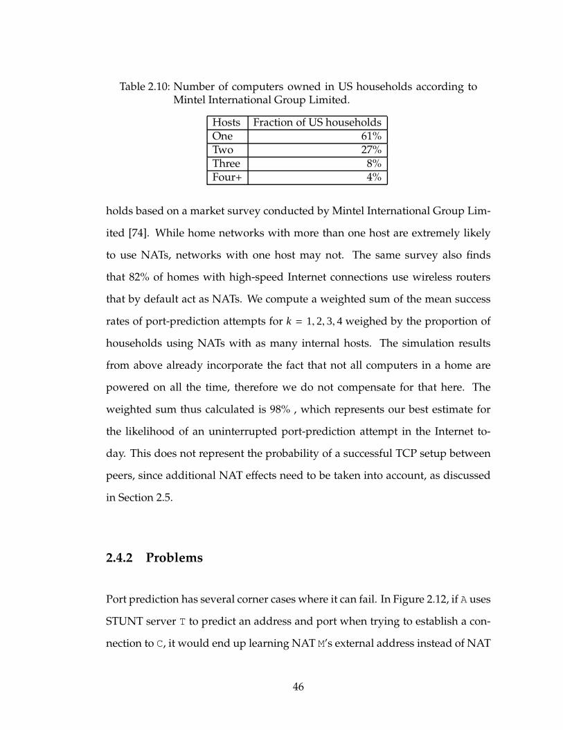
Table 2.10: Number of computers owned in US households according toMintel International Group Limited.
Hosts Fraction of US householdsOne 61%Two 27%Three 8%Four+ 4%
holds based on a market survey conducted by Mintel International Group Lim-
ited [74]. While home networks with more than one host are extremely likely
to use NATs, networks with one host may not. The same survey also finds
that 82% of homes with high-speed Internet connections use wireless routers
that by default act as NATs. We compute a weighted sum of the mean success
rates of port-prediction attempts for k = 1, 2, 3, 4 weighed by the proportion of
households using NATs with as many internal hosts. The simulation results
from above already incorporate the fact that not all computers in a home are
powered on all the time, therefore we do not compensate for that here. The
weighted sum thus calculated is 98% , which represents our best estimate for
the likelihood of an uninterrupted port-prediction attempt in the Internet to-
day. This does not represent the probability of a successful TCP setup between
peers, since additional NAT effects need to be taken into account, as discussed
in Section 2.5.
2.4.2 Problems
Port prediction has several corner cases where it can fail. In Figure 2.12, if A uses
STUNT server T to predict an address and port when trying to establish a con-
nection to C, it would end up learning NAT M’s external address instead of NAT
46
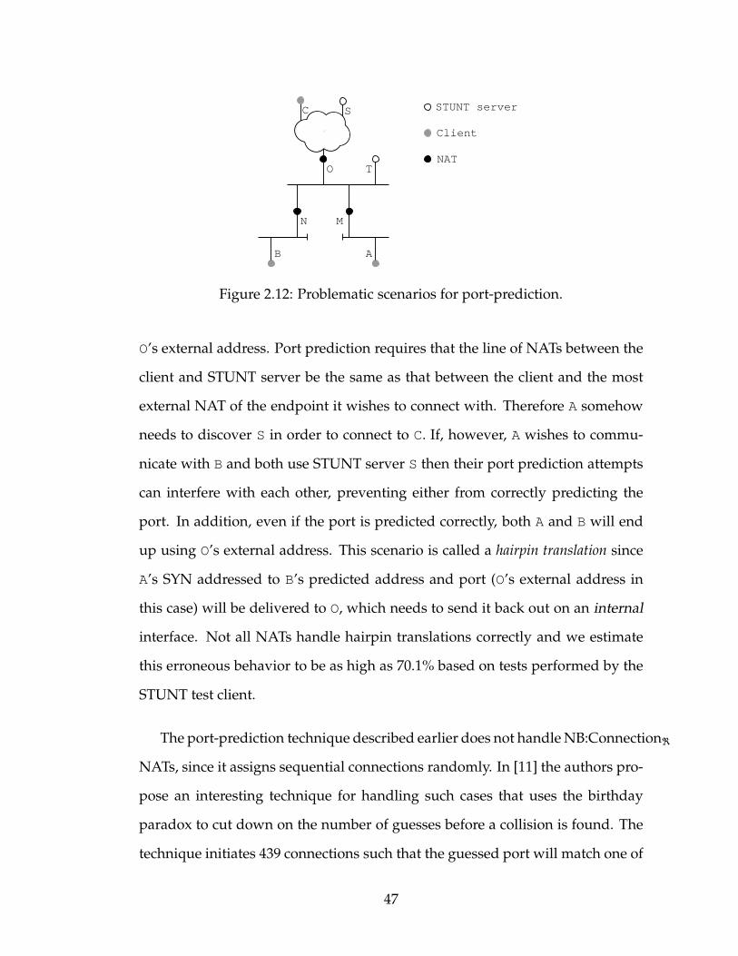
SC
AB
T
N M
O
STUNT server
Client
NAT
Figure 2.12: Problematic scenarios for port-prediction.
O’s external address. Port prediction requires that the line of NATs between the
client and STUNT server be the same as that between the client and the most
external NAT of the endpoint it wishes to connect with. Therefore A somehow
needs to discover S in order to connect to C. If, however, A wishes to commu-
nicate with B and both use STUNT server S then their port prediction attempts
can interfere with each other, preventing either from correctly predicting the
port. In addition, even if the port is predicted correctly, both A and B will end
up using O’s external address. This scenario is called a hairpin translation since
A’s SYN addressed to B’s predicted address and port (O’s external address in
this case) will be delivered to O, which needs to send it back out on an internal
interface. Not all NATs handle hairpin translations correctly and we estimate
this erroneous behavior to be as high as 70.1% based on tests performed by the
STUNT test client.
The port-prediction technique described earlier does not handleNB:Connectionℜ
NATs, since it assigns sequential connections randomly. In [11] the authors pro-
pose an interesting technique for handling such cases that uses the birthday
paradox to cut down on the number of guesses before a collision is found. The
technique initiates 439 connections such that the guessed port will match one of
47
them with 95% probability. Unfortunately, we find that some NATs, like Net-
gear, limit the total number of pending connection attempts to 1000, causing
this approach to quickly stifle the NAT. Fortunately, very few NATs demon-
strate NB:Connectionℜ behavior, mitigating the problem.
2.5 TCP Establishment
In this section, we estimate the success of the various NAT traversal approaches,
as well as report our experience with peer-to-peer TCP establishment for a small
wide-area testbed. The success of TCP NAT-traversal approaches depends on
the behavior of all NATs between the two hosts, as well as the activity of other
hosts behind the NATs. Section 2.3 analyzes a variety of NATs in isolation
while Section 2.4 analyzes competing network activity and its effect on port-
prediction. Combining the results from these sections we can quantitatively
estimate the success of each NAT traversal approach.
We make the following assumptions about the deployment of the TCP-
traversal approaches. We assume that STUNT servers are deployed widely
enough to ensure that for each pair of hosts, there is a STUNT server that meets
the port-prediction requirements and can spoof packets appearing to come from
the mapped address and port of each host. We assume that host network stacks
can be fixed so all software issues at the ends are resolved. Lastly, since we lack
data to model the scenarios presented in Section 2.4.2, we assume the contribu-
tion from such scenarios to be negligible. As a result of these assumptions, our
estimates may be optimistic.
48
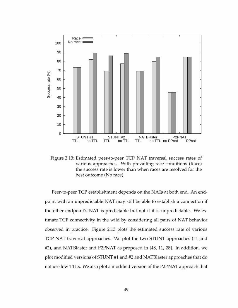
0
10
20
30
40
50
60
70
80
90
100
STUNT #1 TTL no TTL
STUNT #2 TTL no TTL
NATBlaster TTL no TTL
P2PNAT no PPred PPred
Suc
cess
rat
e (%
)
RaceNo race
Figure 2.13: Estimated peer-to-peer TCP NAT traversal success rates ofvarious approaches. With prevailing race conditions (Race)the success rate is lower than when races are resolved for thebest outcome (No race).
Peer-to-peer TCP establishment depends on the NATs at both end. An end-
point with an unpredictable NAT may still be able to establish a connection if
the other endpoint’s NAT is predictable but not if it is unpredictable. We es-
timate TCP connectivity in the wild by considering all pairs of NAT behavior
observed in practice. Figure 2.13 plots the estimated success rate of various
TCP NAT traversal approaches. We plot the two STUNT approaches (#1 and
#2), and NATBlaster and P2PNAT as proposed in [48, 11, 28]. In addition, we
plot modified versions of STUNT #1 and #2 and NATBlaster approaches that do
not use low TTLs. We also plot a modified version of the P2PNAT approach that
49

uses port-prediction. There is a race condition between the SYN packets in some
of these approaches that leads to spurious packets for certain NAT-pairs. The
light-gray bars represent the success rate when each end has an equal chance of
winning the race; this corresponds to simultaneous invocation of the approach
on both ends. The dark-gray bar represents the success rate when the race is
broken in favor of a successful connection; this corresponds to two separate in-
vocations of the approach where for the first invocation, one end is initiated
slightly before the other while for the second invocation, the order is reversed.
The attempt is declared successful if either invocation succeeds in establishing
a TCP connection.
As shown in the graph, the original approaches proposed succeed between
45.5% to 73.2% of the time for P2PNAT and STUNT #1 respectively. Breaking
the race condition in the original STUNT #2 approach by trying it once from
each end boosts its success to 86.0%. Similarly, adding port-prediction to the
P2PNAT approach allows it to handle symmetric NATs, increasing its success
rate to 84.9%. Surprisingly, modifying the original approaches to not use low
TTLs benefits all of them by ∼5%! Breaking the race conditions thus introduced
yields the best success rates of 89.1% and 88.8% for the two modified STUNT
approaches and 84.7% for the modified NATBlaster approach.
The unexpected benefits to not using low-TTL SYNs are explained as fol-
lows. A large fraction of NATs silently drop the first SYN packet (Section 2.3.2)
and only a small fraction of NATs filter inbound SYN packets after the out-
bound SYN packet (Table 2.3.2). Consequently in a large number of cases, the
modified approaches end up triggering TCP simultaneous open even though
they do not intend to. The small penalty they pay for NATs that generate a TCP
50
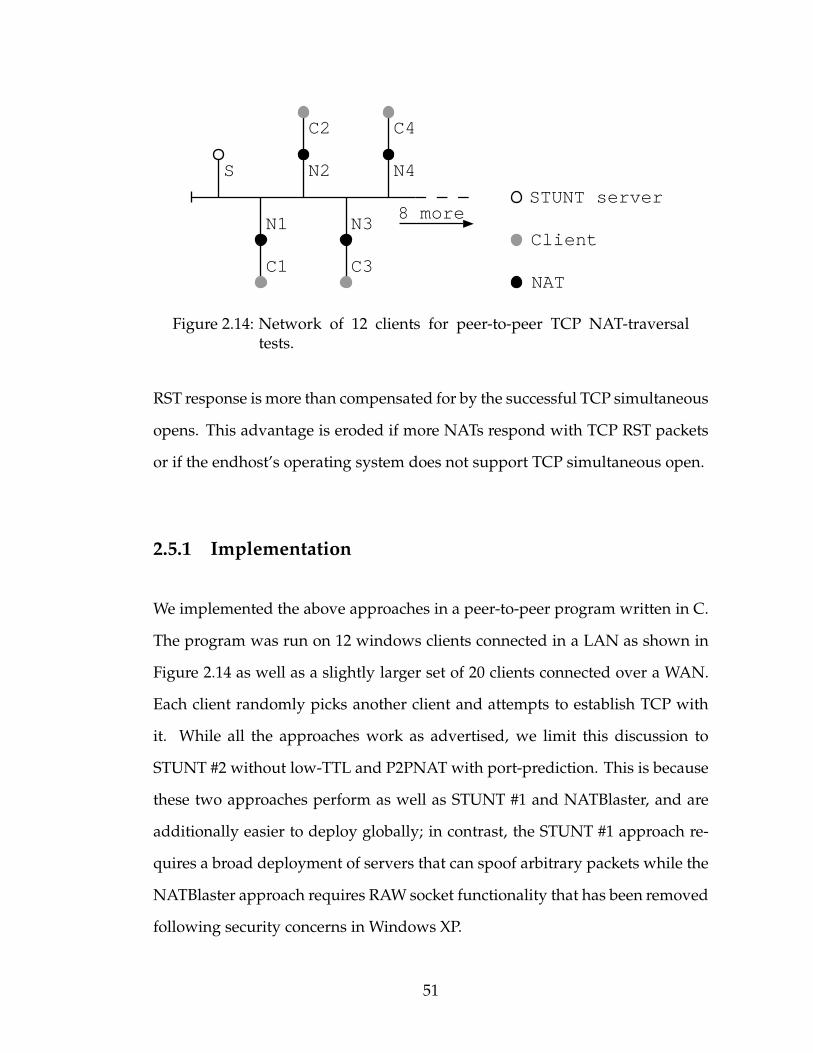
STUNT server
Client
NAT
8 more
C1
C2
C3
C4
N2 N4
N1 N3
S
Figure 2.14: Network of 12 clients for peer-to-peer TCP NAT-traversaltests.
RST response is more than compensated for by the successful TCP simultaneous
opens. This advantage is eroded if more NATs respond with TCP RST packets
or if the endhost’s operating system does not support TCP simultaneous open.
2.5.1 Implementation
We implemented the above approaches in a peer-to-peer program written in C.
The program was run on 12 windows clients connected in a LAN as shown in
Figure 2.14 as well as a slightly larger set of 20 clients connected over a WAN.
Each client randomly picks another client and attempts to establish TCP with
it. While all the approaches work as advertised, we limit this discussion to
STUNT #2 without low-TTL and P2PNAT with port-prediction. This is because
these two approaches perform as well as STUNT #1 and NATBlaster, and are
additionally easier to deploy globally; in contrast, the STUNT #1 approach re-
quires a broad deployment of servers that can spoof arbitrary packets while the
NATBlaster approach requires RAW socket functionality that has been removed
following security concerns in Windows XP.
51
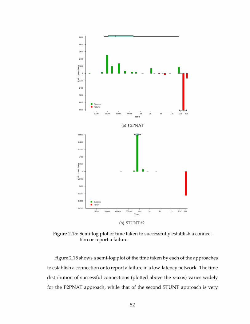
Time
# of
con
nect
ions
00
1200
1200
2400
2400
3600
3600
4800
4800
6000
6000
100ms 200ms 400ms 800ms 1.6s 3s 6s 12s 21s 30s
Success
Failure
(a) P2PNAT
Time
# of
con
nect
ions
00
3700
3700
7400
7400
11100
11100
14800
14800
18500
18500
100ms 200ms 400ms 800ms 1.6s 3s 6s 12s 21s 30s
Success
Failure
(b) STUNT #2
Figure 2.15: Semi-log plot of time taken to successfully establish a connec-tion or report a failure.
Figure 2.15 shows a semi-log plot of the time taken by each of the approaches
to establish a connection or to report a failure in a low-latency network. The time
distribution of successful connections (plotted above the x-axis) varies widely
for the P2PNAT approach, while that of the second STUNT approach is very
52
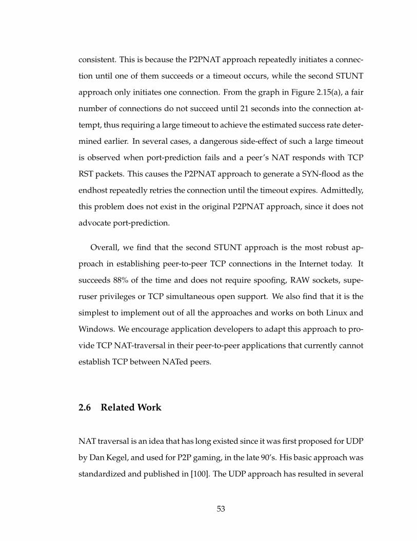
consistent. This is because the P2PNAT approach repeatedly initiates a connec-
tion until one of them succeeds or a timeout occurs, while the second STUNT
approach only initiates one connection. From the graph in Figure 2.15(a), a fair
number of connections do not succeed until 21 seconds into the connection at-
tempt, thus requiring a large timeout to achieve the estimated success rate deter-
mined earlier. In several cases, a dangerous side-effect of such a large timeout
is observed when port-prediction fails and a peer’s NAT responds with TCP
RST packets. This causes the P2PNAT approach to generate a SYN-flood as the
endhost repeatedly retries the connection until the timeout expires. Admittedly,
this problem does not exist in the original P2PNAT approach, since it does not
advocate port-prediction.
Overall, we find that the second STUNT approach is the most robust ap-
proach in establishing peer-to-peer TCP connections in the Internet today. It
succeeds 88% of the time and does not require spoofing, RAW sockets, supe-
ruser privileges or TCP simultaneous open support. We also find that it is the
simplest to implement out of all the approaches and works on both Linux and
Windows. We encourage application developers to adapt this approach to pro-
vide TCP NAT-traversal in their peer-to-peer applications that currently cannot
establish TCP between NATed peers.
2.6 Related Work
NAT traversal is an idea that has long existed since it was first proposed for UDP
by Dan Kegel, and used for P2P gaming, in the late 90’s. His basic approach was
standardized and published in [100]. The UDP approach has resulted in several
53
working documents and Internet drafts that classify UDP behavior of NATs [56]
and propose standardization of the same [7]. The area of TCP NAT-traversal
without explicit control of the NAT, however, is fairly new. Several approaches
have been analyzed in this chapter [48, 24, 11, 28] and have been demonstrated
to traverse NATs in the current Internet. In [28], the authors present a similar
studywhere the authors test a small subset of UDP and TCPNAT characteristics
for a number of NATs. We present the first broad study of NAT behavior and
peer-to-peer TCP establishment for a comprehensive set of TCP NAT traversal
techniques over a wide range of commercial NAT products.
Protocols such as UPnP [73] and MIDCOM [111] allow endhost applications
to explicitly control the NAT in order to facilitate peer-to-peer connections. The
downside of this type of approach is that they require that these protocols exist
and are enabled in the NAT. An application developer cannot depend on either
of these, and so for the time being they are not an attractive option.
Another endhost approaches to TCP connectivity includes TURN [97],
where TCP data is proxied by a third party. This third party represents a po-
tential network bottleneck. Teredo [54] allows IPv6 packets to traverse IPv4
NATs by tunneling IPv6 over UDP. Here, TCP runs natively in the sense that it
is layered directly above IPv6. Teredo has been implemented in the Windows
OS, but to our knowledge is not widely used.
2.7 Conclusion and Future Work
This chapter presents the first measurement study of a comprehensive set of
NAT characteristics as they pertain to TCP. While this study shows that there
54
are a significant number of problems with TCP traversal of current NATs, it
nevertheless gives us much to be optimistic about. Even with existing NATs,
which have not been designed with TCP NAT traversal in mind, we are able to
show a 88% average success rate for TCP connection establishment with NATs
in the wild, and a 100% success rate for pairs of certain common types of NAT
boxes. These numbers are especially encouraging given that only a couple years
ago, it was widely assumed that TCP NAT traversal was simply not possible.
While a failure rate of 11% is not acceptable for many applications, the users
of those applications at least have the option of buying NAT boxes that allow
TCP traversal (e.g. Linksys). Additionally, NAT vendors have the option of
designing their NAT boxes to be more TCP friendly; to this end, RFC 5283 [45]
lays out guidelines for NAT vendors.
This study is limited in several respects. First, we did not test all existing
NAT boxes. For the most part our study was limited to NAT boxes available in
North America. Second, our field test is too small and biased to be able to accu-
rately predict success rates broadly. Using market data helps, but even this data
was limited in scope and in detail. Third, we tested only for home NATs. Port
prediction in enterprise networks for “delta” type NATs will succeed less often,
and it would be useful to measure this. Fourth, although TCP NAT traversal
techniques apply broadly to firewalls, we did not test firewalls outside the con-
text of NAT. Nor did we test IPv4-IPv6 translation gateways. Finally, like most
measurement studies, this is a snapshot in time. Indeed, during the course of
this project, new versions of the same NAT product exhibited different behavior
from previous versions. Moving forwards, we hope that our TCP NAT traversal
test suite can continue to be used to broaden our knowledge of NAT and firewall
characteristics as well as to track trends in NAT products and their deployment.
55
CHAPTER 3
SHUTUP: REDUCING UNWANTED TRAFFIC
An ongoing problem in the Internet is that of large scale DoS attacks
launched from botnets, worms, and port scanning. A wide variety of systems
have been deployed or proposed that address one or more of these types of
unwanted traffic, including [137, 136, 2, 61, 6, 69] that require in-network infras-
tructure help to filter DoS traffic, and [132, 131, 105] for worm detection and
mitigation. By requiring infrastructure deep in the network, these approaches
are forced to forfeit the benefits of an E2E deployment model [103] that has en-
abled the edge of the Internet to evolve much faster than the middle. It is no
surprise, perhaps, that DoS attacks remain commonplace, and the Internet re-
mains vulnerable to flash worms.
More recently, the authors of [4], propose a new approach of filtering DoS
traffic at the source endhost; however, to do so securely, the authors rely on a
clean-slate redesign of the network layer that adds cryptographic accountability
to each packet. While we like this idea of filtering at the offending endhost,
requiring a clean-slate Internet Protocol is far too heavy-weight. We believe
DoS attacks can be mitigated using E2E techniques with far more light-weight
mechanisms.
In this chapter, we explore a new point in the solution design space. In par-
ticular, we propose a pure end-to-end ShutUp Service that does not require any
changes to the protocol stack, nor require any in-network infrastructure. In
essence, a host that receives packets can tell the sending host to rate-limit or
stop sending packets to it. This is enforced at the sending host by a tamper-
56
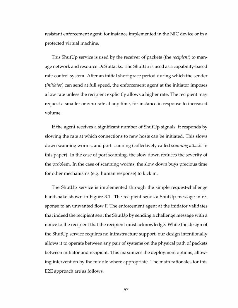
resistant enforcement agent, for instance implemented in the NIC device or in a
protected virtual machine.
This ShutUp service is used by the receiver of packets (the recipient) to man-
age network and resource DoS attacks. The ShutUp is used as a capability-based
rate-control system. After an initial short grace period during which the sender
(initiator) can send at full speed, the enforcement agent at the initiator imposes
a low rate unless the recipient explicitly allows a higher rate. The recipient may
request a smaller or zero rate at any time, for instance in response to increased
volume.
If the agent receives a significant number of ShutUp signals, it responds by
slowing the rate at which connections to new hosts can be initiated. This slows
down scanning worms, and port scanning (collectively called scanning attacks in
this paper). In the case of port scanning, the slow down reduces the severity of
the problem. In the case of scanning worms, the slow down buys precious time
for other mechanisms (e.g. human response) to kick in.
The ShutUp service is implemented through the simple request-challenge
handshake shown in Figure 3.1. The recipient sends a ShutUp message in re-
sponse to an unwanted flow F. The enforcement agent at the initiator validates
that indeed the recipient sent the ShutUp by sending a challengemessage with a
nonce to the recipient that the recipient must acknowledge. While the design of
the ShutUp service requires no infrastructure support, our design intentionally
allows it to operate between any pair of systems on the physical path of packets
between initiator and recipient. This maximizes the deployment options, allow-
ing intervention by the middle where appropriate. The main rationales for this
E2E approach are as follows.
57

Figure 3.1: Basic ShutUp operation: Recipient NM sends SHUTUP for un-wanted data. Initiator SM validates ShutUp was sent by pur-ported recipient before blocking the flow at the source. Noncesprotect against spoofing.
• By putting enforcement at the misbehaving host, we maximize the scenar-
ios whereby the ShutUp service can be effective. For instance, hosts within
an enterprise or datacenter would be protected from each other.
• By allowing recipient endhosts to issue ShutUp requests, we maximize
the potential of integrating with external mechanisms to detect unwanted
packets, such as those based on application-specific knowledge (e.g. [92]).
At the same time, by allowing firewalls or even routers on the data path
to issue ShutUp requests, we can exploit the broader knowledge a firewall
has due to its vantage point.
• The ShutUp service requires no new changes to existing protocols or to
infrastructure equipment. While we do not want to pretend that glob-
ally deploying ShutUp (or any other defense system) is easy, the deploy-
ment model for ShutUp is intriguing because it could be accomplished
58
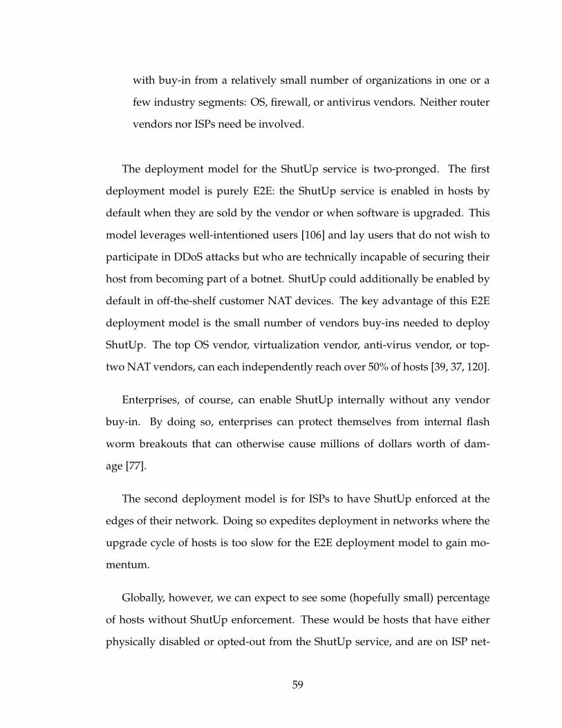
with buy-in from a relatively small number of organizations in one or a
few industry segments: OS, firewall, or antivirus vendors. Neither router
vendors nor ISPs need be involved.
The deployment model for the ShutUp service is two-pronged. The first
deployment model is purely E2E: the ShutUp service is enabled in hosts by
default when they are sold by the vendor or when software is upgraded. This
model leverages well-intentioned users [106] and lay users that do not wish to
participate in DDoS attacks but who are technically incapable of securing their
host from becoming part of a botnet. ShutUp could additionally be enabled by
default in off-the-shelf customer NAT devices. The key advantage of this E2E
deployment model is the small number of vendors buy-ins needed to deploy
ShutUp. The top OS vendor, virtualization vendor, anti-virus vendor, or top-
two NAT vendors, can each independently reach over 50% of hosts [39, 37, 120].
Enterprises, of course, can enable ShutUp internally without any vendor
buy-in. By doing so, enterprises can protect themselves from internal flash
worm breakouts that can otherwise cause millions of dollars worth of dam-
age [77].
The second deployment model is for ISPs to have ShutUp enforced at the
edges of their network. Doing so expedites deployment in networks where the
upgrade cycle of hosts is too slow for the E2E deployment model to gain mo-
mentum.
Globally, however, we can expect to see some (hopefully small) percentage
of hosts without ShutUp enforcement. These would be hosts that have either
physically disabled or opted-out from the ShutUp service, and are on ISP net-
59
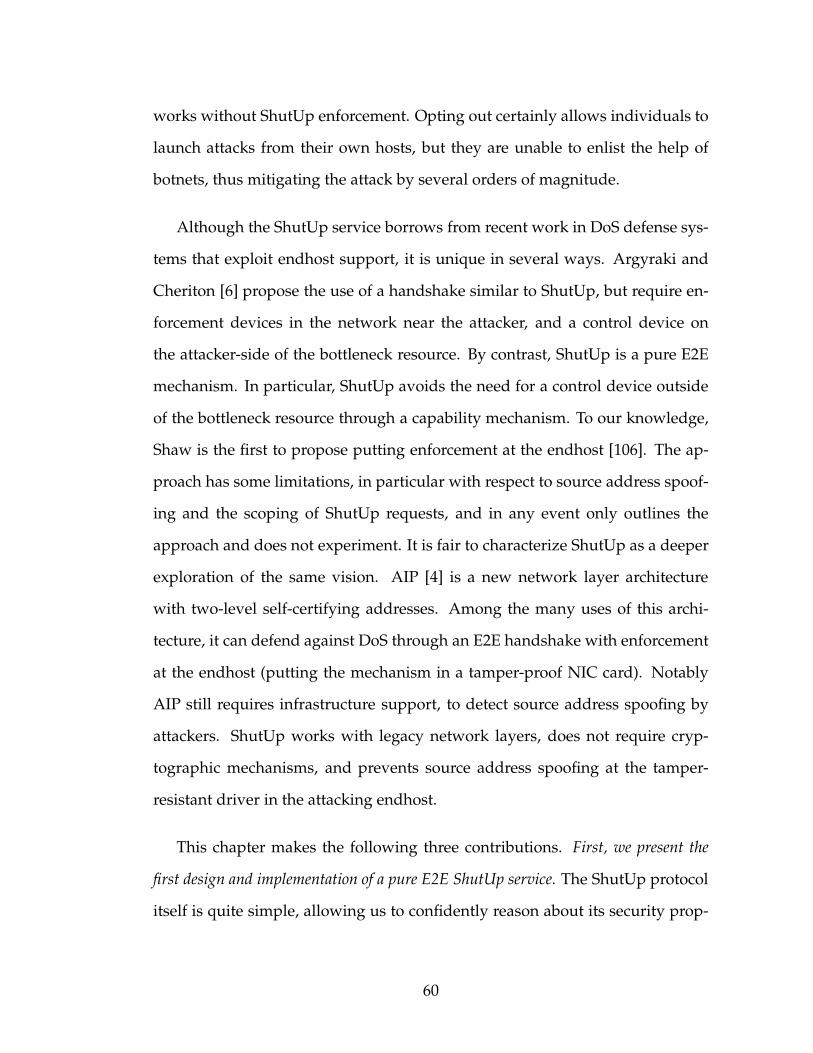
works without ShutUp enforcement. Opting out certainly allows individuals to
launch attacks from their own hosts, but they are unable to enlist the help of
botnets, thus mitigating the attack by several orders of magnitude.
Although the ShutUp service borrows from recent work in DoS defense sys-
tems that exploit endhost support, it is unique in several ways. Argyraki and
Cheriton [6] propose the use of a handshake similar to ShutUp, but require en-
forcement devices in the network near the attacker, and a control device on
the attacker-side of the bottleneck resource. By contrast, ShutUp is a pure E2E
mechanism. In particular, ShutUp avoids the need for a control device outside
of the bottleneck resource through a capability mechanism. To our knowledge,
Shaw is the first to propose putting enforcement at the endhost [106]. The ap-
proach has some limitations, in particular with respect to source address spoof-
ing and the scoping of ShutUp requests, and in any event only outlines the
approach and does not experiment. It is fair to characterize ShutUp as a deeper
exploration of the same vision. AIP [4] is a new network layer architecture
with two-level self-certifying addresses. Among the many uses of this archi-
tecture, it can defend against DoS through an E2E handshake with enforcement
at the endhost (putting the mechanism in a tamper-proof NIC card). Notably
AIP still requires infrastructure support, to detect source address spoofing by
attackers. ShutUp works with legacy network layers, does not require cryp-
tographic mechanisms, and prevents source address spoofing at the tamper-
resistant driver in the attacking endhost.
This chapter makes the following three contributions. First, we present the
first design and implementation of a pure E2E ShutUp service. The ShutUp protocol
itself is quite simple, allowing us to confidently reason about its security prop-
60

erties and the correctness of the implementation. The enforcement module, for
instance, is implemented in less than 200 lines of Python code. This small foot-
print alsomaximizes the deployment options. For instance, the ShutUp protocol
may be implemented in a NIC or on small wireless devices. It requires no en-
cryption or key distribution, allowing us to avoid the associated complexity and
hazards. Second, we analyze the ShutUp service’s effectiveness as a DoS prevention
mechanism. We show, for instance, that a host with 10Mbps of access bandwidth
can completely stop a 10Gbps attack from ∼10,000 ShutUp-enabled hosts behind
broadband links. Finally, we analyze the ShutUp service’s effectiveness as a defense
against scanning attacks. Of particular interest here is the trade-off between effec-
tiveness (how quickly scanning attacks are discovered and how much they are
slowed down) and false positives (identifying legitimate activity as scanning
attacks). For example, we show that ShutUp slows down scanning worms to
the same degree as existing approaches while reducing false positives by two
orders of magnitude.
3.1 ShutUp Details
This section starts with an overview of the ShutUp components, followed by a
detailed description of its operation.
3.1.1 ShutUp Components
There are two components in ShutUp, ShutUp modules (SM) and notification mod-
ules (SM). As illustrated in Figure 3.2, an SM is deployed at the initiator, out
61
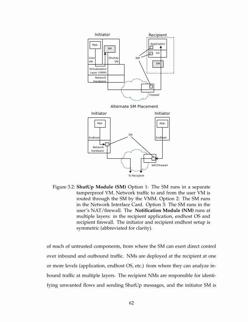
Figure 3.2: ShutUp Module (SM) Option 1: The SM runs in a separatetamperproof VM. Network traffic to and from the user VM isrouted through the SM by the VMM. Option 2: The SM runsin the Network Interface Card. Option 3: The SM runs in theuser’s NAT/firewall. The Notification Module (NM) runs atmultiple layers: in the recipient application, endhost OS andrecipient firewall. The initiator and recipient endhost setup issymmetric (abbreviated for clarity).
of reach of untrusted components, from where the SM can exert direct control
over inbound and outbound traffic. NMs are deployed at the recipient at one
or more levels (application, endhost OS, etc.) from where they can analyze in-
bound traffic at multiple layers. The recipient NMs are responsible for identi-
fying unwanted flows and sending ShutUp messages, and the initiator SM is
62

Table 3.1: ShutUp primitives and message contents
ShutUp PrimitiveSHUTUP(FLOW, APPNAME, NONCER , TTL, IDNM)THROTTLE(FLOW, APPNAME, NONCER , TTL, RATE, IDNM )
Recipient NM directs initiator SM to ShutUpor throttle a flow (5-tuple; wildcards allowed).
CHALLENGE(FLOW, NONCER , NONCEI , IDNM )Initiator SM requests confirmation of request
RESPONSE(FLOW, NONCEI )DISCLAIM(FLOW, NONCEI )
Recipient NM confirms or denies original requestQuery PrimitiveQUERYAPPNAME(FLOW, NONCEI )APPNAME(FLOW, APPNAME, NONCEI )
SM queries remote NM for application name (toblock scanning attacks before probe is sent)
responsible for enforcing the recipient’s decision and for correct operation of
the ShutUp protocol. Since an endhost can both initiate and receive flows, NMs
and an SM are deployed in each endhost. The SM is the only trusted component
in the system; the NM is not a trusted component since it cannot affect flows to
other recipients.
3.1.2 Basic Operation
ShutUp offers two primitives (Table 3.1.2). The primary primitive, SHUTUP, is
used to block or rate-limit individual flows. The basic ShutUp operation illus-
trated in Figure 3.1 is fairly straightforward. The recipient NM sends a SHUTUP
request (unencrypted) in response to unwanted traffic. The request includes a
nonce (NONCER) for verification purposes. To save state, the nonce may be com-
puted as a cryptographic hash of the flow identifier and a local time-varying
63
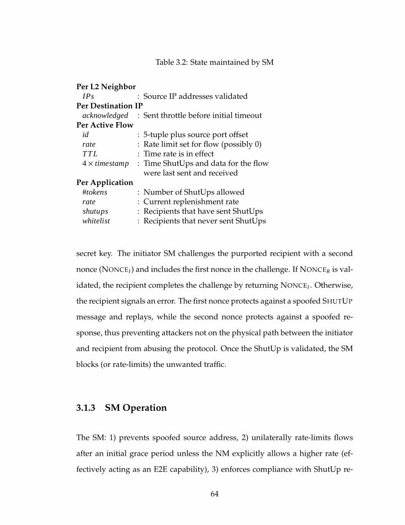
Table 3.2: State maintained by SM
Per L2 NeighborIPs : Source IP addresses validated
Per Destination IPacknowledged : Sent throttle before initial timeout
Per Active Flowid : 5-tuple plus source port offsetrate : Rate limit set for flow (possibly 0)TT L : Time rate is in effect4 × timestamp : Time ShutUps and data for the flow
were last sent and receivedPer Application
#tokens : Number of ShutUps allowedrate : Current replenishment rateshutups : Recipients that have sent ShutUpswhitelist : Recipients that never sent ShutUps
secret key. The initiator SM challenges the purported recipient with a second
nonce (NONCEI ) and includes the first nonce in the challenge. If NONCER is val-
idated, the recipient completes the challenge by returning NONCEI . Otherwise,
the recipient signals an error. The first nonce protects against a spoofed SHUTUP
message and replays, while the second nonce protects against a spoofed re-
sponse, thus preventing attackers not on the physical path between the initiator
and recipient from abusing the protocol. Once the ShutUp is validated, the SM
blocks (or rate-limits) the unwanted traffic.
3.1.3 SM Operation
The SM: 1) prevents spoofed source address, 2) unilaterally rate-limits flows
after an initial grace period unless the NM explicitly allows a higher rate (ef-
fectively acting as an E2E capability), 3) enforces compliance with ShutUp re-
64
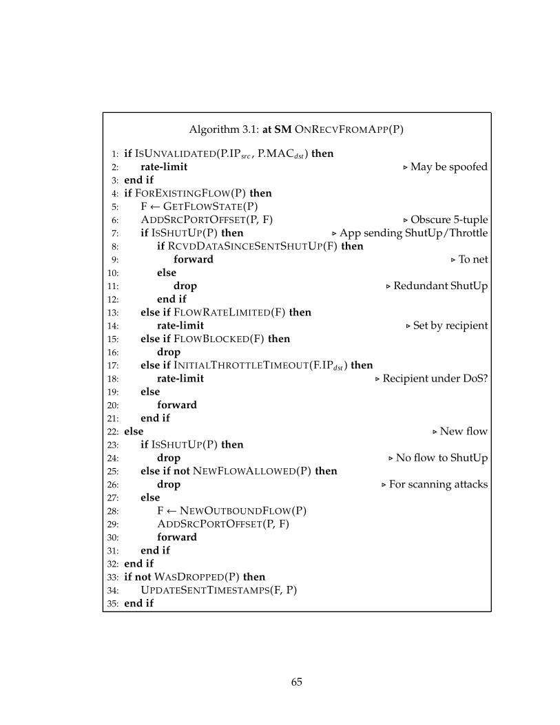
Algorithm 3.1: at SM ONRECVFROMAPP(P)
1: if ISUNVALIDATED(P.IPsrc , P.MACdst ) then2: rate-limit ⊲May be spoofed3: end if4: if FOREXISTINGFLOW(P) then5: F← GETFLOWSTATE(P)6: ADDSRCPORTOFFSET(P, F) ⊲ Obscure 5-tuple7: if ISSHUTUP(P) then ⊲ App sending ShutUp/Throttle8: if RCVDDATASINCESENTSHUTUP(F) then9: forward ⊲ To net10: else11: drop ⊲ Redundant ShutUp12: end if13: else if FLOWRATELIMITED(F) then14: rate-limit ⊲ Set by recipient15: else if FLOWBLOCKED(F) then16: drop17: else if INITIALTHROTTLETIMEOUT(F.IPdst ) then18: rate-limit ⊲ Recipient under DoS?19: else20: forward21: end if22: else ⊲New flow23: if ISSHUTUP(P) then24: drop ⊲ No flow to ShutUp25: else if not NEWFLOWALLOWED(P) then26: drop ⊲ For scanning attacks27: else28: F← NEWOUTBOUNDFLOW(P)29: ADDSRCPORTOFFSET(P, F)30: forward31: end if32: end if33: if not WASDROPPED(P) then34: UPDATESENTTIMESTAMPS(F, P)35: end if
65

Algorithm 3.2: at SM ONRECVFROMNET(P)
1: SETVALIDATED(P.IPdst , P.MACsrc ) ⊲ Learn IP2: if FOREXISTINGFLOW(P) then3: F← GETFLOWSTATE(P)4: if ISSHUTUP(P) then ⊲ Got ShutUp/Throttle5: if SENTDATASINCERCVDSHUTUP(F) then6: SENDCHALLENGE(P)7: else8: drop ⊲ Redundant ShutUp9: end if10: else if ISVALIDCHALLENGERESPONSE(P) then11: if ISFORTHROTTLE(P) then12: RATELIMITFLOW(F, P.RATE, P.TTL)13: else14: BLOCKFLOW(F, P.TTL)15: CHECKSCANNING(P.IPsrc , P.APP)16: end if17: else18: SUBDSTPORTOFFSET(P, F) ⊲ Unobscure 5-tuple19: deliver ⊲ To app20: end if21: else ⊲New flow22: if ISSHUTUP(P) then23: drop ⊲ No flow to ShutUp24: else25: F← NEWINBOUNDFLOW(P)26: deliver27: end if28: end if29: if not WASDROPPED(P) then30: UPDATERCVDTIMESTAMPS(F, P)31: end if
66

quests, and 4) detects and slows scanning attacks. The state maintained at the
SM is listed in Table 3.1.3. The SM operations when forwarding a packet from
the application to the network and vice versa are listed in pseudo-code in Algo-
rithms 3.1 and 3.2 respectively, with key fragments highlighted in the descrip-
tion below.
Preventing Address Spoofing
A host that can spoof source addresses can launch an attack without allow-
ing ShutUp requests to reach it. To prevent this, the SM must prevent source
spoofing. The difficulty in doing this lies in determining what an acceptable
source address is. A firewall can be configured with this information. An end-
host SM must however determine whether the endhost is authorized to use the
present address. It is hard for the SM to make this determination, especially if
the endhost statically assigns the address. However, we consider cryptographic
solutions [3] unnecessarily complex in this context.
The SM rate-limits sending “unvalidated” packets to each layer-two neigh-
bor, where validation requires receiving a packet for the purported IP address
from that L2 neighbor (Algorithm 3.1.1 and 3.2.1). Since the SM does not know
which addresses are spoofed and which not, rate-limiting, rather than blocking,
is necessary to give an unvalidated address a chance to be validated. If the ad-
dress is in fact spoofed, the validation does not succeed as long as the spoofing
host is not on the same subnet as the recipient, because responses are not routed
back to the SM, and the rate-limit is maintained indefinitely. Since virtually all
applications send packets in both directions [65], validation is effectively piggy-
67

backed on application traffic. The approach does not require any infrastructure
or changes to the protocol stacks.
We choose to validate the IP address and destination MAC pair rather than
just the IP address. Doing so foils two colluding endhosts on the same network
attempting to validate a spoofed address. For instance, a colluding L2 neighbor
may trigger validation by sending a packet to the endhost’s MAC with the des-
tination address set to the spoofed address — the resulting validation whitelists
the spoofed address, but for use with that neighbor only. Therefore for the secu-
rity of the mechanism, the SM must prevent spoofing the source MAC address.
But since the SM has exclusive access to the physical network hardware, this is
not difficult. (Section 3.2 discusses the case where the colluding host does not
have an SM.)
Delivering ShutUp Messages
ShutUp messages contain the 5-tuple (protocol number, and source and desti-
nation address and port) of the data flow they refer to. The messages are sent
along the datapath encoded as ICMP destination unreachable packets with the
5-tuple contained in the encapsulated payload headers. The reason for this is
that NATs and firewalls today already translate and forward ordinary ICMP
messages related a flow [110], and so will transparently forward ShutUp mes-
sages. Another option would be to use a shim layer between IP and the trans-
port, which we avoid since it modifies the protocol stack, thus breaking existing
middleboxes and application firewalls.
68
Flow Initiation and ShutUps
A general problem with using multiway handshakes in DoS prevention mech-
anisms is that the validation message is likely to be dropped at the bottle-
neck link. If the attack is large enough, very few validation messages will get
through, and it will take a long time to slow the attack. To deal with this, the
SM enforces a rate-limit on flows that must be explicitly lifted by the recipient
NM. The rate-limiting operates as follows.
The SM initially allows the application to send at an unlimited rate on new
flows, but only for a short time interval. The interval is picked conservatively
(10 seconds in our simulations) within which time the recipient must send a
THROTTLE message indicating the allowed rate-limit for the flow. If neither
a THROTTLE nor a SHUTUP is received, the SM automatically rate-limits the
flow (Alg. 3.1.18). When the throttle’s TTL expires, the SM again rate-limits the
flow (to 10kbps in our simulations). The NMmust periodically send throttles to
maintain the flow at high speed.
In addition to rate-limiting flow packets, the SM limits both inbound and
outbound ShutUp requests. For outbound ShutUp requests sent by the applica-
tion, the SM ensures that the associated flow exists, and has received data since
the last ShutUp was sent (Alg. 3.1.11). This gates ShutUp messages with ap-
plication traffic, preventing endhosts from abusing ShutUp messages to launch
certain attacks. Similarly, the SM ignores inbound ShutUp requests for flows
that do not exist and flows on which no data has been sent since the last ShutUp
was received. These safeguards require the SM to maintain per-flow state and
timestamps.
69
Legacy recipients: The automatic rate-limiting above does not affect legit-
imate flows to NM-enabled recipients, but creates tradeoffs for legacy recipi-
ents that lack a NM. On the one hand, the rate-limit mitigates DoS attacks on
legacy recipients incapable of sending ShutUps. While on the other hand, le-
gitimate flows to legacy recipients that last more than a few seconds are unnec-
essarily slowed. To avoid this latter issue, the SM disables the rate-limit if it
receives any packet for the flow from the receiver. But to prevent an attacker
from abusing this mechanism, the SM makes it hard for the attacker to spoof
a flow packet, for instance by adding a random offset to the source port in the
5-tuple1 (Alg. 3.1.29); an attacker may attempt to brute force the 5-tuple, but the
SM can detect such an attempt. The security implications of this mechanism are
considered in Section 3.2.
Slowing Scanning Attacks
ShutUp usually slows the scanning application rather than cordoning off the
entire infected endhost, in order to reduce collateral damage to other applica-
tions. Identifying the application from just the flow 5-tuple is notoriously hard.
Firewalls often resort to complex deep-packet inspection to identify application
flows to dynamically selected ports. ShutUp avoids this complexity by having
the NM provide the application name in the ShutUp message. Doing so is not
hard for the NM, since it is deployed in the recipient application or endhost OS
and can readily query the application. Since the NM is not trusted in any event,
the name reported by the application is not verified.
1Like NAT except only the local port for locally initiated flows is modified. Since in-bound packets can be unambiguously delivered (Alg. 3.2.18), NAT traversal approaches arenot needed.
70
At its simplest, the SM considers an anomalous rate (per unit time) of
ShutUps an indication of a scanning attack, at which point new flow initiations
for the application are rate-limited (lines 3.2.15 and 3.1.25). In principle, a num-
ber of other options can be used for detecting scanning attacks, for instance
based on the fraction of flows that receive ShutUps [131, 105], or more complex
introspection of the user application [36]. We base our choice on the simplicity
of the approach and the low number of false positives we encountered, as we
report in later sections.
The SM algorithm for slowing scanning attacks is as follows. The SM main-
tains a token bucket for each application. A token is consumed by each ShutUp
from a distinct recipient. Flow initiations to recipients are blocked if no tokens
are present; however, flows to a dynamic list of previously successfully con-
tacted recipients are not affected. Over time, tokens are replenished at a config-
ured rate up to a maximum value, but persistent scanning decreases this rate at
which tokens are replenished. The reasoning behind these design decisions are
as follows.
Distinct recipients: Consuming one token formultiple ShutUps from the same
recipient limits the potential damage caused by a (malicious) recipient. For this
purpose, the SM maintains per-application state consisting of recipients that
have previously sent ShutUps.
Blocking by application: While the application name is piggybacked on
ShutUp requests as mentioned above, at flow initiation time the packet 5-tuple
does not, in general, identify the application. Since the first flow packet can it-
self exploit a vulnerability [77], this creates a chicken-and-egg scenario where
the first flow packet must be blocked if it is for the offending application, but
71

to determine the application, the flow must be allowed and a ShutUp sought.
ShutUp breaks this dependency with the Query primitive (Table 3.1.2), which
is a simple request-response exchange whereby the SM queries the NM for the
name of the application the flow would reach if it were to be allowed. The
query is not needed for well-known ports and is only invoked when the host
is believed to be participating in an attack. Legacy recipients without an NM
cannot respond to these queries.
New Recipients: To mitigate the impact of false positives, the SM maintains
a list of recipients contacted previously that have never sent a ShutUp for the
application. While flow initiations to new recipients are rate-limited during a
suspected scanning attack, flows to recipients on this list are whitelisted.
Rate limiting flow initiation: A common concern with thresholds is how the
threshold is picked. A low static threshold creates false positives, which we
determined in our dataset to be bursty, whereas a threshold high enough to ac-
commodate bursts allows sub-threshold scans that does not adequately slow the
attacker. For this purpose, ShutUp uses a dynamic threshold: the rate at which
new flow initiations are allowed is picked randomly (our implementation uses
an exponential distribution around a configured mean), and this rate is halved
every time the token-bucket underflows. In effect, the rate-limit allows large
but short bursts of ShutUps for legitimate applications, while forcing persistent
scans to a much lower rate.
72
3.1.4 NMOperation
A single recipient NM cannot detect the wide range of unwanted traffic we are
interested in (address scans, DoS, intrusions etc.). The design therefore accom-
modates separate collaborating NMs operating at various layers. Each NM tags
ShutUp messages with its ID and responds to challenges intended for it. That
said, how unwanted traffic is detected, for instance distinguishing between flash
crowds and DoS attacks, is beyond the scope of this thesis. We rely on exist-
ing or future methods of detecting these attacks at the application, endhost OS,
and recipient firewall, including IDS (e.g. [88]), CAPTCHAs [125], and exploit
detectors (e.g. [20]) as applicable. Given these detection mechanisms, ShutUp
answers the question of what to do once the attack is detected.
Out of the three, the design of the endhost OS NM is non-trivial. If the recip-
ient application is not running, the endhost OS must determine whether or not
to send a ShutUp. The choice is not clearcut because sending a ShutUp prevents
the source from reattempting the flow, at least until the ShutUp expires. Such
ShutUps hinder interactive applications such as web browsing if the web server
is momentarily unavailable. Further, if enough endhosts generate false posi-
tives, it unduly triggers the scanning defense at the initiator. This affects P2P
applications, for example, where stale membership information results in peers
attempting to contact a recently running (or crashed) application for some time.
To avoid these false positives, applications in ShutUp register an application-
specific “linger” time when binding to a port (fewminutes for P2P applications,
infinity for server applications). The endhost OS does not send ShutUps for an
unbound port until the linger period expires. For legacy applications, the OS
NMmay be configured with a small default linger time.
73
3.1.5 Protecting the SM
One of the challenges in implementing ShutUp is protecting the SM from being
subverted by endhost malware, while at the same time not placing undue con-
straints on the resources available to it. There are a number of E2E deployment
options, for instance, implementing the SM as part of the NIC firmware, in the
NAT/firewall router, or as a virtualization layer. In the virtualization scenario,
user software and the SM are run in separate virtual machines (VM), and only
the ShutUp VM is allowed access to the physical network interfaces. Traffic to
and from the user VM is routed through the ShutUp VM (Figure 3.2), where the
SM can filter packets as necessary. Designing the SM for the NIC, NAT/firewall,
or ISP router near the initiator is, of course, more straightforward.
There are a number of reasons why we believe a VM-based deployment is
a good choice. First, desktop virtualization has come of age. VMs are used
today to allow users to run games, or business software on otherwise unsup-
ported operating systems [124, 86]. Second, a VM has access to more resources
(multiple cores, memory) than a hardware implementation (e.g. NIC). Based
on trace-driven simulations, we estimate a typical endhost will require around
256kB of SM state isolated from the user; tamperproof memory in hardware is
expensive, whereas a VMM can virtualize main system memory. Third, a VM
protected by a VMM provides a trusted platform [35] while being easy to up-
date once deployed. Updating hardware securely requires physical access. In
contrast, a VM can be securely upgraded by the VMM (assuming the VMM has
not been compromised). Finally, a VM is needed to demultiplex ShutUps for
middleboxes. With a hardware or NAT/firewall SM, a ShutUp for a middlebox
(webproxy, virtual private network tunnel endpoint) resulting from traffic initi-
74
ated by a single user would affect the entire middlebox, thus affecting all users
behind the middlebox. In a VM, a trusted version of the middlebox service can
run alongside the SM to redirect ShutUps to the offending user.
3.1.6 Deployment
Enterprises can deploy NMs and SMs with or without buy-in from hardware
and software vendors. The ability to protect enterprise hosts from one another,
particularly during internal worm outbreaks, provides incentive to do so.
Buy-in from the major OS vendors would result in rapid endhost NM de-
ployment, potentially through automated software update mechanisms. De-
ploying the SM securely, however, requires an environment isolated from mal-
ware already present in the endhost. Buy-in from the top five PC vendors would
result in 49% deployment [38]; buy-in from the top five home router vendors
would result in 79% [120]; and, buy-in from the top five anti-virus vendors
would result in 91% global deployment [37]. It is therefore conceivable that
a concerted effort by 10 or so companies could realize a near global ShutUp
deployment in a few years time. At the same time, it isn’t necessary for all
concerned vendors to buy in. As we show later, even a partial deployment is
beneficial.
3.2 Attacking ShutUp
In this section we consider attacks on ShutUp components and mechanisms
through which an attacker may attempt to disrupt flow establishment.
75
Attacker Model: We assume that the attacker has complete physical control
over a small number of hosts. In particular, the attacker can disable the SM on
these hosts. In addition, the attacker has software control over a much larger
number of compromised hosts.
We initially assume the attacker is not on the datapath between the initiator
and recipient. An on-path attacker, for instance on a compromised router, can
disrupt communication by dropping or modifying packets enroute even in the
absence of ShutUp. We later relax this assumption to consider eavesdroppers
— on-path attackers that can observe but not modify in-flight packets.
Software Compromise: Vulnerabilities in the SM implementation or virtual-
ization layer could allow an attacker to gain control of the SM through software
methods. In case of compromise, the VMM can restore a pristine SM from read-
only media, and rely on automatic software update mechanisms to apply all
relevant patches. Physical access is required only if the VMM itself is compro-
mised or for updates to the readonly media.
Compromising the NM is less severe. A compromised NM may fail to
ShutUp unwanted flows, or worse, ShutUp flows that are not unwanted. In the
first case, NMs deployed at other layers can still ShutUp unwanted flows. In the
second case, the danger is not so much to the recipient, since such an attacker
can block flows passing through the NM evenwithout cooperation from the SM,
but rather to the initiator for being falsely implicated of unwanted traffic. How-
ever, the attacker must compromise multiple NMs at recipients contacted by the
initiator to successfully trigger the scanning defense, mitigating the severity of
the attack.
76

Spoofed Packets: In order to spoof packets at an unlimited rate without
disabling the SM, the attacker must be able to complete the address validation
process by spoofing the MAC address of the first-hop router, which requires
physical access to a second endhost on the same network. With software-only
access to a given network, an attacker can at best hijack an address in that net-
work, but since the endhost would receive all packets for the hijacked address,
in particular ShutUp messages as well, there is little impact on ShutUp for do-
ing so. Consequently, the number of networks an attacker can spoof packets
from is limited by the number of hosts the attacker has physical access to — sig-
nificantly better than today, where up to 25% of edge ASs allow spoofing [10].
If an attacker compromises a legacy (no SM) host on the subnet, it can fake the
MAC address of the router and then create arbitrary addresses on compromised
SM-enabled hosts. If the attacker already has such a foothold in a legacy host,
however, it can in any event spoof arbitrary addresses.
In order to successfully fake ShutUps, an attacker must be able to eavesdrop
packets. This is because, as previously mentioned, all ShutUp messages must
be validated before any action is taken by the SM, and the attacker must be
able to guess the nonces involved to fake the validation. But since nonces are
not encrypted, an eavesdropper can win a validation race. However, since the
eavesdropper cannot stop the in-flight challenge, the real recipient will generate
a conflicting response. The SM can therefore at least detect the presence of an
eavesdropper, although not which of the responses is legitimate. In any event,
an eavesdropper can disrupt flows even without ShutUp, so ShutUp does not
introduce a qualitatively new attack.
77
Abusing ShutUpMessages: ShutUpmessages are gated by application traf-
fic at the SM. The mechanism prevents an attacker from flooding a victim with
ShutUp messages absent an application flow between the two. Even when a
flow exists, the number of ShutUp messages that can be sent is upper bound by
the number of flow packets. The same mechanism gates reflection attacks con-
sisting of ShutUp challenges if an attacker spoofs a stream of ShutUp messages;
the amplification factor for such attacks is at most one.
Avoiding Initial Rate-Limit: An attacker may attempt to disable the initial
rate-limit for unacknowledged flows by abusing the mechanism intended for
legacy recipients. Doing so requires the attacker to guess the random initiator
port, which requires on average 215 guesses. After the first few guesses, the
SM can detect the attack and lock in the rate-limit such that only a validated
THROTTLE may lift it. Thus an attacker cannot disable the initial rate-limit, nor
affect flows to NM-equipped recipients, and can at best target flows to legacy
recipients to be rate-limited; the recipient can counter by deploying an NM.
Triggering Scanning Defense: An attacker can trigger the scanning defense
at an endhost by convincing the initiator to contact recipients not expecting the
flows. For instance, a malicious website may return a webpage with inline
image URLs pointing to recipients not running a webserver. Alternatively, a
compromised router enroute to multiple destinations may fake ShutUps. While
ShutUp does not defend against such attacks, ShutUp limits the impact. First,
in the case of a duped application, the scanning defense only applies to the
one application and not to other applications running on the endhost. Second,
the defense does not affect communication to recipients that have never previ-
ously ShutUp the endhost, allowing the application to operate with diminished
78
reachability. Finally, as the defense is lifted unless the application is persistently
scanning, a legitimate application can resume normal operations after caution-
ing the user against reattempting flows to the problematic destinations.
3.3 Stopping DoS with ShutUp
The ShutUp service can be used to mitigate both application-level as well as
network-level DoS attacks. At the application level, the efficacy depends on
how quickly and accurately the attack is detected, which is contingent on detec-
tion mechanisms external to ShutUp; once detected, the application NM sends
ShutUps to the attackers. Defending against network-level DoS, where attack-
ers saturate a bottleneck link, is more involved, because the ShutUp challenge-
response mechanism must operate through the same bottleneck.
If the bandwidth of challenges incident at the bottleneck link is B, and aggre-
gate attacker bandwidth is X times the bandwidth of the bottleneck link, then
only B/X challenges will cross the bottleneck. To put in numbers, if a small num-
ber of attackers, say 5000, command a bandwidth 10 times that of a 100Mbps
bottleneck, an incident challenge bandwidth of 10Mbps would ShutUp around
1000 attackers per second assuming 128 byte challenge packets, stopping the
attack in 5 seconds.
Relying solely on the challenges getting through the bottleneck suffices for
small attacks but not large attacks. This is because the incident challenge band-
width B required to maintain the same rate of validated ShutUps increases lin-
early with X. However, since challenges are driven directly by ShutUp requests,
B is upper bound by the victim’s upload bandwidth, which remains fixed as X
79

increases. Moreover, B is more realistically a fraction, typically one-tenth, of the
bottleneck bandwidth assuming ∼1kB attack packets. This is because the victim
can, at best, generate one ShutUp per attack packet crossing the bottleneck, each
of which results in a challenge. Generating more ShutUps or challenges creates
the possibility of amplification attacks. Since B cannot be increased indefinitely,
ShutUp decreases X for large DoS attacks.
In large DoS attacks (e.g. X > 20), the SM enforced automatic rate-limit af-
ter the first few seconds cuts X by several orders of magnitude. The rate-limit
alone does not address congestion at the bottleneck, as even with the dimin-
ished bandwidth, the attackers can be numerous enough to saturate the bottle-
neck. The purpose of the rate-limit is to increase the fraction of challenges in
the attack traffic, which is possible because B is independent of X as long as the
bottleneck is saturated. This allows the challenge-response mechanism to kick
in more effectively and stop large DoS attacks.
The above discussion assumes that only the NM at the victim is responding
to the attack, however, other NMs may additionally be involved. For instance,
ShutUp challenges to an ISPNMupstream of the bottleneck linkwould succeed.
Or in case of an endhost behind the bottleneck colluding with attackers by not
sending ShutUps for traffic crossing the bottleneck, a firewall NM between the
bottleneck and the colluding endhost may instead send ShutUps to protect other
endhosts behind the bottleneck. Overall ShutUp requires an NM to be present
somewhere along the attack path to stop a DoS.
Simulation Results: We used ns-2 to simulate how well ShutUp mitigates
DoS attacks. We use a fan-in topology where a varying number of attackers
(from 10 to 9600) send traffic to a bottleneck link; the recipient is on the other
80
side of the bottleneck. The topology models a DoS where attack traffic does
not self-interfere except at the bottleneck. In the Internet, attackers sharing a
common link other than the bottleneck may cause additional packet loss. Nev-
ertheless, since ShutUp is entirely end-to-end (or edge-to-edge), we expect such
AS- and router-level topology to have little impact. To convince ourselves of
this, we simulated ShutUp on the router-level topology collected by the Rock-
etfuel project [108] and a sampling of the AS topology collected by the Route-
Views [119] project and found the results to be qualitatively similar; however,
these simulations were restricted to small attacks (upto X = 100) due to simula-
tor limitations.
The latency between the attacker and the bottleneck is parameterized by
end-to-end RTT data collected by the Meridian project [133]. Each attacker
sends 1Mbps of attack traffic. The bottleneck link is set to 10Mbps with drop-
tail queuing. All other links are set to 10Gbps. We simulate attack traffic from
10Mbps to 9.6Gbps, that is between 1 and 960 times the bottleneck bandwidth.
To determine the contribution of the ShutUpmechanism and automatic rate-
limit, we compare the effectiveness of ShutUp with and without the rate-limit.
When enabled, the SM automatically rate-limits traffic to 10Kbps after 10 sec-
onds. The choice of these parameters is primarily to explore the scaling proper-
ties of the DoS defensemechanisms in ShutUp rather than to guide deployment.
Figure 3.3 plots a representative attack with aggregate bandwidth 240 times
the bottleneck link bandwidth. The figure is split in two parts: the top plots
the bottleneck link utilization over time, while the bottom plots the number of
attackers that have not received a validated ShutUp. We observe three distinct
phases during the attack. Phase 1 lasts for 10 seconds where the bottleneck
81
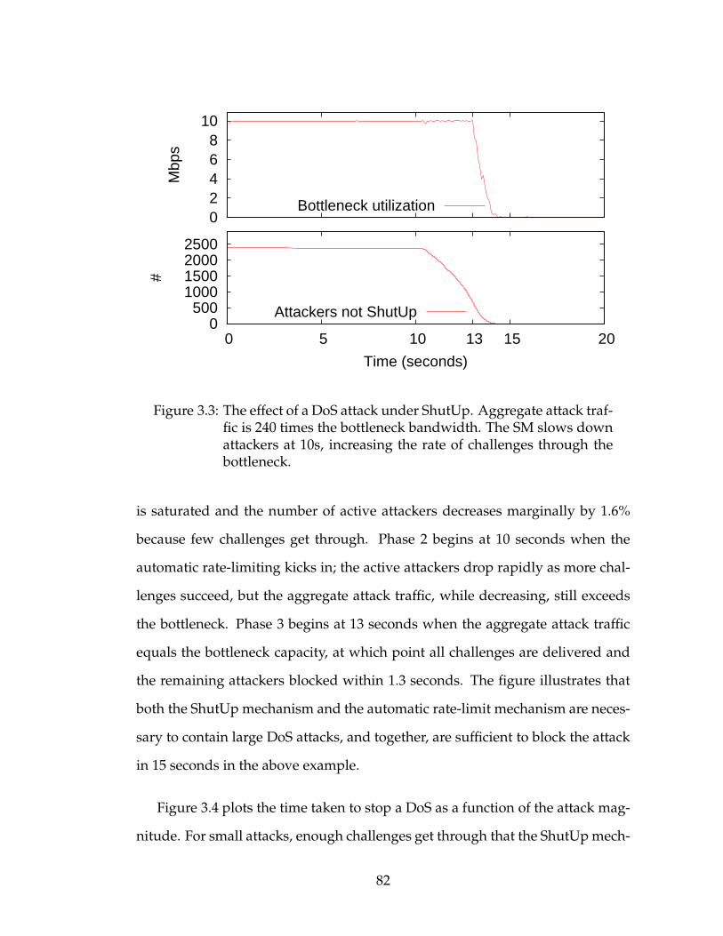
0 2 4 6 8
10
Mbp
s
Bottleneck utilization
0 500
1000 1500 2000 2500
0 5 10 13 15 20
#
Time (seconds)
Attackers not ShutUp
Figure 3.3: The effect of a DoS attack under ShutUp. Aggregate attack traf-fic is 240 times the bottleneck bandwidth. The SM slows downattackers at 10s, increasing the rate of challenges through thebottleneck.
is saturated and the number of active attackers decreases marginally by 1.6%
because few challenges get through. Phase 2 begins at 10 seconds when the
automatic rate-limiting kicks in; the active attackers drop rapidly as more chal-
lenges succeed, but the aggregate attack traffic, while decreasing, still exceeds
the bottleneck. Phase 3 begins at 13 seconds when the aggregate attack traffic
equals the bottleneck capacity, at which point all challenges are delivered and
the remaining attackers blocked within 1.3 seconds. The figure illustrates that
both the ShutUp mechanism and the automatic rate-limit mechanism are neces-
sary to contain large DoS attacks, and together, are sufficient to block the attack
in 15 seconds in the above example.
Figure 3.4 plots the time taken to stop a DoS as a function of the attack mag-
nitude. For small attacks, enough challenges get through that the ShutUpmech-
82

0
10
20
30
40
50
60
10x 100x 1000x
Tim
e (s
)
Attack magnitude (logscale)
ShutUps onlyShutUps + auto ratelimit
Figure 3.4: Time taken to stop a DoS attack as attack magnitude increases
anism alone can completely stop the attack, but there is a threshold (X = 20)
beyond which the automatic rate-limiting is needed to keep pace with the at-
tack magnitude. Only when the attack magnitude increases by two orders of
magnitude — the same factor as our chosen automatic rate-limit parameter —
does the combined approach experience a disproportionate increase. Overall,
ShutUp is able to stop attacks ranging widely in their magnitude.
To determine the effectiveness of a partial deployment, we simulated attacks
where we varied the fraction of legacy attackers that do not have an SM, and are
therefore immune to ShutUps. We simulated ShutUp deployments from 90% to
10% holding the aggregate bandwidth of legacy attackers constant at 90% of the
bottleneck link. The results were not surprising: in all cases, ShutUp is able
to desaturate the bottleneck in under two seconds by stopping all SM-enabled
attackers. ShutUp reduces attack bandwidth by the same fraction as the degree
of deployment (i.e. 90% reduction for 90% deployment) — what we might call
83
“incremental improvability” — the more endhosts in the botnet population that
have it, the better the results.
3.4 Slowing Scanning Worms
The scanning defense in ShutUp allows worm outbreaks to be contained (or
slowed) using the service. A scanning worm, by its nature, propagates by dis-
covering and infecting vulnerable endhosts. There are several ways how such
worms may receive ShutUps. ShutUps may result, for instance, from probes
to endhosts not running the vulnerable application, probes to honeynets [107]
or network telescopes [76], attack packets to vulnerable endhosts protected by
application-level defenses [20], traffic monitored by in-network intrusion detec-
tion systems [88] and firewalls.
As mentioned, the SM slows down new flow initiations when a threshold
rate of ShutUps is crossed. In contrast, threshold randomwalk (TRW) based de-
tectors [131, 105] place bounds on the fraction of bad flows to good flows. Both
approaches have their pros and cons. TRW can detect an extremely low rate
of scanning, but is susceptible to collusion where worm instances can maintain
a fixed fraction by establishing “good” flows amongst themselves or with bot-
net members to absolve an equal number of probes. ShutUp is not affected by
such collusion, but does not target sub-threshold scanning; to the extent the ran-
domness and exponential rate-limit in ShutUp compel the worm to scan slowly,
ShutUp buys time for other approaches to detect and disinfect compromised
hosts. Consequently, we focus on fast scanning worms.
84

ShutUp ignores worm probes that do not generate a response (not even a
ShutUp), for instance probes to non-existent addresses or to hosts behind NATs;
interpreting such silent probes as implicit ShutUps would increase the ShutUp
frequency and thus reduce the reaction time, but it would also increase false
positives (Section 3.5.2). Inside an enterprise, last-hop routers could certainly
be configured to send ShutUps for such probes. On the Internet, however, we
expect policy will prevent stealthy NATs and firewalls from sending ShutUps
for such probes [46]. Fortunately, as we report below, the impact of ignoring
these silent probes is minimal for a typical worm attack. We hope to revisit this
design decision in the future if the behavior of legitimate applications improves.
Simulation Results: We simulated worm outbreaks in a custom simulator to
determine howwell ShutUp performs as compared to the TRW-based approach
proposed in [131]. We parameterized our simulator with Internet census data
collected by the ANT project [51]. As per the data, out of the 2.8 billion allo-
cated unicast public IPv4 addresses, 187 million (6.7%) respond to probes. The
remaining addresses are either unused, or used by stealthy hosts. We simulate a
Code Red-like worm [78] that scans at a peak rate of ∼11 addresses per second,
and has a vulnerable population of 359K endhosts. The vulnerable endhosts
are distributed uniformly at random among the 2.8B allocated addresses. If the
worm probes a vulnerable address, the destination is instantly infected (unless
already infected) and begins scanning. Otherwise, if the probe is to the 6.7%
addresses that send a response, a ShutUp is simulated, else the probe times out
(remaining 93% of the time). At t = 0, the attacker infects 1000 vulnerable hosts
to initiate the outbreak.
Figure 3.5 plots the number of infected hosts as a function of time. Without
85
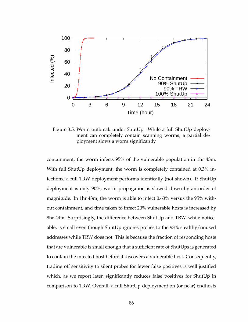
0
20
40
60
80
100
0 3 6 9 12 15 18 21 24
Infe
cted
(%
)
Time (hour)
No Containment90% ShutUp
90% TRW100% ShutUp
Figure 3.5: Worm outbreak under ShutUp. While a full ShutUp deploy-ment can completely contain scanning worms, a partial de-ployment slows a worm significantly
containment, the worm infects 95% of the vulnerable population in 1hr 43m.
With full ShutUp deployment, the worm is completely contained at 0.3% in-
fections; a full TRW deployment performs identically (not shown). If ShutUp
deployment is only 90%, worm propagation is slowed down by an order of
magnitude. In 1hr 43m, the worm is able to infect 0.63% versus the 95% with-
out containment, and time taken to infect 20% vulnerable hosts is increased by
8hr 44m. Surprisingly, the difference between ShutUp and TRW, while notice-
able, is small even though ShutUp ignores probes to the 93% stealthy/unused
addresses while TRW does not. This is because the fraction of responding hosts
that are vulnerable is small enough that a sufficient rate of ShutUps is generated
to contain the infected host before it discovers a vulnerable host. Consequently,
trading off sensitivity to silent probes for fewer false positives is well justified
which, as we report later, significantly reduces false positives for ShutUp in
comparison to TRW. Overall, a full ShutUp deployment on (or near) endhosts
86
can completely stop a worm, while a partial deployment can slow it down sig-
nificantly.
3.5 Evaluation
To evaluate the impact on real endhosts, we evaluated ShutUp using datasets
from an enterprise environment, an academic environment, and a home envi-
ronment.
Implementation: We implemented a proof-of-concept SM in Python. The
SM processes connection events generated by Bro [88], infers ShutUps from
TCP errors, and for each new outbound flow, passes a verdict whether the flow
would have been allowed, rate-limited, or blocked had the SM been running
on the endhost during data collection. The implementation is 153 lines long,
demonstrating the simplicity of the SM. While our implementation allowed us
to rapidly prototype (and refine) the ShutUp design, and provided insights into
the impact on legitimate flows, performance and auditability of the SM software
stack are important deployment concerns that we believe are best addressed us-
ing a non-interpreted language.
Trace Data: Our enterprise dataset consists of a month-long trace of packet
headers for all traffic to and from endhosts, primarily employee laptops, for a
major corporation. The data was collected at the endhost, and thus includes traf-
fic even when the endhost was outside the enterprise. This is the ideal dataset
for evaluating an endhost SM. The trace contains little peer-to-peer filesharing
traffic as enterprise policy forbid the use of P2P applications. The trace covers
357 users during the first quarter of 2007 with the median trace lasting 26 days.
87
Processed through Bro, the trace contains about 24.5M TCP flows initiated by
the endhosts to 111K addresses.
Our university dataset consists of a 6-day trace of packet headers from end-
hosts in the computer science department of a major university collected at the
border router. The dataset is ideal for evaluating a firewall SM. As with the
enterprise, policy discourages the use of P2P filesharing applications. The data
contains 5M flows from 1680 IP addresses during a week when the university
was in session.
Our home-user dataset consists of an 8-day trace of primarily BitTorrent traf-
fic collected in a home network. It contains 37K flows over which around 5Gb
of data was transferred in both directions, which we use to counter the lack of
P2P filesharing traffic in the other two datasets.
Methodology: We treat any error responses from the endhost as ShutUps;
this typically includes TCP RST packets and non-transient ICMP errors in re-
sponse to the initial SYN. Flows over which at least one byte of application data
is exchanged do not generate ShutUps regardless of how the flow is terminated
(e.g. FIN exchange, RST packets, or TCP timeout). Flows where the initial SYN
packet does not elicit any response within 3 seconds are treated as unacknowl-
edged flows. We discard other TCP flows (e.g. when a SYN ACK is seen but
no data is transferred); such flows comprise less than 0.1% of our data. We do
not analyze UDP traffic as we cannot, in general, determine if a flow would
have generated a ShutUp. Furthermore, because we do not have packet pay-
loads, our evaluation is limited to ShutUps that an endhost or firewall NMmay
generate; consequently, application-level errors over a successful TCP flow (e.g.
SMTP errors) count as successful flows.
88

3.5.1 Tuning Parameters
Our choice of system parameters is driven by our data.
IP Spoofing Limit: Users in our enterprise trace use, in the median case, 24
unique source IP addresses over the duration of the trace, with 10% of users us-
ing more than 70. The number is significantly higher than that measured for the
average Internet user (1 IP address over 2 weeks) [16], which can be explained
by the difference in vantage points as [16] measures from the perspective of a
content provider. On average, the SM must validate a source IP address and
MAC pair every 7 hours.
87% of the time the address is validated within one second, typically by the
first application flow. In the worst case, an endhost attempted 1 flow per sec-
ond for 18 minutes before eliciting any response; in such cases, the endhost OS
may be configured to ping the first-hop router shortly after assigning a new IP
address to more quickly validate the address. Our implementation rate-limits
packets with unvalidated addresses MAC pairs to a burst of at most 60 packets
in the first ten minutes, and one packet perminute after that. The rate-limit does
not impact 99% of address changes.
Linger period and ShutUp TTL: In order to determine the minimum linger
period to be observed by the endhost NM, and the TTL for ShutUp requests, we
plot the CDF of the time elapsed until a flow to a destination succeeds after the
first encountered failure in Figure 3.6. The y-value represents the fraction of re-
tries that would have succeeded had a failed flow not been incorrectly ShutUp
for a given TTL value (x-axis). Curiously, the plot for our enterprise trace is lin-
ear on a semi-log scale across six orders of magnitude — a phenomenon well
89

0
20
40
60
80
100
1 10 100 1000 10000 100000 1e+06 1e+07
CD
F o
f suc
cess
ful r
etrie
s (%
)
Time since first failure (seconds)
Figure 3.6: Determining the impact of endhost OS ShutUp TTL and lingertime on legitimate retries
worth investigating in its own right. In essence, the longer an application has
been failing, the longer it is expected to keep failing, whereas the more recent
the failure, the more likely it is that a quick retry will succeed, something which
we term “failure momentum”. A minimum linger time of 2 seconds prevents
35% of retries from being incorrectly blocked. Beyond this, the NM may dy-
namically pick the TTL in proportion to the length of the outage, however, our
implementation uses a static value of 60 seconds.
Scanning threshold: In order to determine a threshold that does not impede
legitimate flows while placing a bound on scanning activity, we require an or-
acle to separate benign traffic from suspicious traffic in our dataset. For this
purpose we use the TRW-based scan detection algorithm proposed in [131] to
flag potential scanners in our enterprise dataset. We assume the 182 users not
flagged are least likely to be scanners. For these users, a minimum threshold of
9 ShutUps perminute is necessary to not trigger the scanning defense. Adding a
90
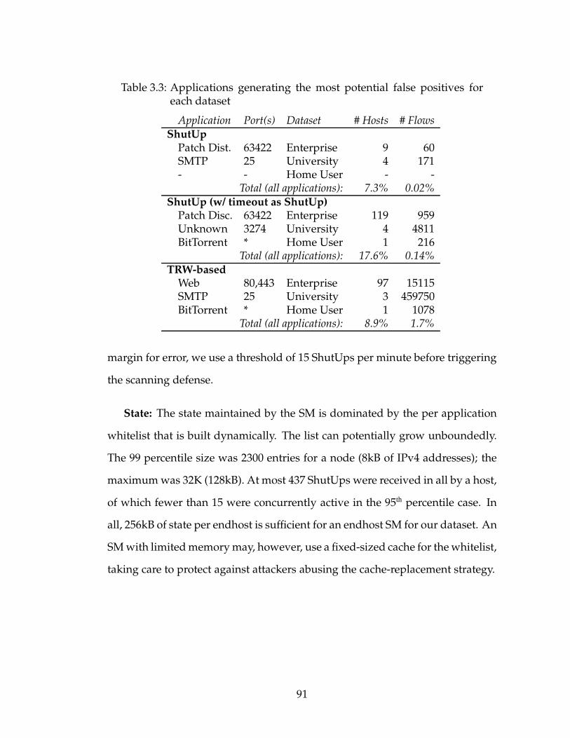
Table 3.3: Applications generating the most potential false positives foreach dataset
Application Port(s) Dataset # Hosts # FlowsShutUpPatch Dist. 63422 Enterprise 9 60SMTP 25 University 4 171- - Home User - -
Total (all applications): 7.3% 0.02%ShutUp (w/ timeout as ShutUp)Patch Disc. 63422 Enterprise 119 959Unknown 3274 University 4 4811BitTorrent * Home User 1 216
Total (all applications): 17.6% 0.14%TRW-basedWeb 80,443 Enterprise 97 15115SMTP 25 University 3 459750BitTorrent * Home User 1 1078
Total (all applications): 8.9% 1.7%
margin for error, we use a threshold of 15 ShutUps per minute before triggering
the scanning defense.
State: The state maintained by the SM is dominated by the per application
whitelist that is built dynamically. The list can potentially grow unboundedly.
The 99 percentile size was 2300 entries for a node (8kB of IPv4 addresses); the
maximumwas 32K (128kB). At most 437 ShutUps were received in all by a host,
of which fewer than 15 were concurrently active in the 95th percentile case. In
all, 256kB of state per endhost is sufficient for an endhost SM for our dataset. An
SMwith limitedmemorymay, however, use a fixed-sized cache for thewhitelist,
taking care to protect against attackers abusing the cache-replacement strategy.
91
3.5.2 False Positives
We evaluated ShutUp on all three datasets. For comparison, we also evaluated
the TRW-based approach proposed in [131], and a modified version of ShutUp
that treats unacknowledged flows as implicit ShutUps. We use well-known port
numbers to determine the application name in the enterprise and university
trace, while for the home user trace, we tag all flows generated by BitTorrent as
such regardless of the port number. For ShutUp, we use the parameters above.
For TRW, we primarily use the parameters in [131], which the authors tune us-
ing multiple datasets and conclude are applicable in general. We also tested
TRW with higher thresholds, and while this reduced the false positives quanti-
tatively, it did not do so qualitatively: the same applications generate the most
false positives.
For each approach, we consider flows that the approach decided to block,
but which did in fact exchange data during the trace. We manually examined
the most egregious endhosts and eliminated blatant scanners based on sequen-
tial address or port scans. However, since we lack payload data to automatically
disambiguate certain cases, some successful flows may in fact be successful
scan attempts; as such, our results identify legitimate applications potentially
affected by ShutUp. Table 3.5.2 plots the top applications generating potential
false positives for each dataset. Overall, ShutUp results in fewer false positives
(0.02% versus 1.7%) for the following reasons:
Enterprise: In the enterprise case, as mentioned previously, the linger mech-
anism reduces the number of ShutUps generated due to momentary outages.
False positives in ShutUp stem from the automated patching application which
performs distributed scanning to quickly discover unpatched endhosts; we ex-
92
pect IT to configure enterprise endhost NMs to not send ShutUps for benign
scanning authorized by the enterprise, or filter ShutUps for such applications in
the network.
University: The outbound mail-server has a ratio of 70% unsuccessful flows,
largely due to undeliverable bounces to spammessages, triggering the scanning
defense. The whitelist in ShutUp allows flows to legitimate mail-servers that
have never sent a ShutUp to continue unimpeded.
Home User: BitTorrent generates a large number of unacknowledged flows,
presumably to other clients behind NATs, but potentially also to clients that
have recently left the cloud. Since ShutUp ignores such flows, the scanning
defense is not triggered.
3.6 Extensions to ShutUp
In this section we present some extensions to ShutUp that enhance the service
provided by the SM. Additionally, we promise cake to those who contact us
with ideas for other interesting extensions. In general, extensions to ShutUp
present new potential vulnerabilities that need to be considered.
Weighted ShutUps: The SM can give more importance to ShutUps for more
severe violations or from authoritative sources. For instance, a ShutUp from
an application protected by Vigilante [20], could instantly trigger the scanning
defense. Such ShutUps would need to carry proof of their authenticity, such as
Vigilante’s self-certifying alert that the SM can verify in the ShutUp VM.
93

Collaborating SMs: The SM can collaborate with nearby SMs to determine
the uncleanliness [19] of the local network. The metric may be used to adjust
the sensitivity of the SM to better contain worms.
Initiator behavior: The SM can provide information about the initiator’s
past behavior, such as the diversity of recipients contacted, to new recipients.
The NM can compare this to the expected diversity for the application [60] to
help determine the legitimacy of the flow.
Wireless Contention: Wireless nodes sharing the broadcast medium with
an overly-chatty node could request it to ShutUp. Once the SM verifies that a
majority of wireless neighbors concur, it can throttle the application reducing
contention.
3.7 Related Work
Receiver oriented communication models are not new. IPmulticast [23], i3 [112],
and off-by-default [8] all allow the recipient to choose what data it receives.
Multicast is not intended for one-to-one communication, i3 requires infrastruc-
ture, and off-by-default requires modification to routers and Internet routing. In
contrast, ShutUp is end-to-end (or edge-to-edge) and requires no infrastructure.
The work closest to the ShutUp service, either because they use a challenge-
response approach or because they propose tamper-proof mechanisms in the
attacking endhost [106, 4, 6], are discussed in Section 4.
Many DoS mitigation approaches operate by installing filters along the at-
tack path. The simplest approach is to thin attack traffic using passive and active
94
filters at the upstream ISP [93]. Taking this idea further, endhosts may install fil-
ters in gateway routers, or in routers progressively closer to the source [6, 70, 69].
Combining filtering with explicit authorization, routers upsteam of the bottle-
neck may be configured to, by default, impede packets not explicitly autho-
rized by the endhost through capability nonces [136, 137]. A second class of ap-
proaches [1, 34, 67, 2, 61] dissipate DoS attacks before absorbing the unwanted
traffic. One approach is to use a currency, such as bandwidth, to grant access
through filters at network choke points [128]. In contrast, ShutUp explores a
hybrid design point in between filtering and capabilities, thereby retaining both
higher effectiveness and greater resistance to attackers. Furthermore, ShutUp
filters DoS traffic at the source (or its firewall), preventing attack traffic from
consuming any network resources. Finally, ShutUp, more generally, handles
scanning attacks within the same architecture.
Worm containment has been subject of much recent work. In [79], the au-
thors provide guidelines applicable to any worm containment approach. One
approach is to rate-limit all flow initiations or to bound the diversity of recip-
ients [132, 41]. Such approaches may negatively impact certain classes of ap-
plications such as peer-to-peer applications. Targeted more directly at worms,
TRW [58] detects scanning worms from the recipient firewall’s perspective.
Turning the TRW approach inside-out and operating at a router upstream of the
infected endhost, worms may be detected and contained based on an anoma-
lous fraction of failed flows for a particular port number [131, 105]. While the
SM can use any combination of these mechanisms, ShutUp extends to applica-
tions that use dynamic ports.
95
Much work has been done in detecting unwanted traffic both in the net-
work and at the recipient endhost that ShutUps complements. In the network,
traffic can be classified as portscans [58], worms [62, 104], DoS attacks [55], flash
crowds [57], and of dubious origin [22]. Classification can be performed through
correlation [116], rule-based matching [63], or entropy in feature sets [66] in,
potentially aggregated, flow parameters. At the endhost, application-agnostic
exploit detection [20, 107], as well as application-specific detection based on
common usage profiles, and deviations therefrom [92, 114] have been proposed.
More active methods of detection include CAPTCHAs [80, 59] or tracking user-
activity [87] to verify the presence of a human, and puzzle auctions [129] to
rate-limit attacks. The NM can directly use these and future approaches to de-
tect unwanted traffic to ShutUp.
3.8 Summary
In this chapter, we propose ShutUp, an end-to-end (or edge-to-edge) service
to reduce unwanted traffic in the Internet. We thoroughly explore the design
space and determine the small set of mechanisms required to mitigate, and in
many cases completely stop, a wide range of unwanted traffic ranging fromDoS
attacks to scanning worms. ShutUp does not require any additional infrastruc-
ture or changes to the protocol stack. Through simulations we find that ShutUp
scales well to defend against large scale DoS attacks up to three orders of mag-
nitude in excess of bottleneck links, and can slow scanning worms by an order
of magnitude. Using extensive trace data from three environments we establish
that ShutUp’s impact on legitimate traffic is minimal. Overall, we believe there
is a compelling case to be made for containing unwanted traffic at the ends.
96

That being said, there is still a lot work to be done before ShutUp can be
deployed. While ShutUp is easily deployable in enterprises, and globally de-
ployable with buy-in from only a few vendors, it is likely that deployment, at
least initially, will be driven by ISPs. Convincing ISPs would require, first, a
more thorough analysis of the security implications of deploying an in-network
SM, and second, an evaluation of the performance and scaling characteristics of
the SM in an ISP setting. In any event, we believe that our biggest challenge is
more social than technical, or economical. While the model pushes cost onto the
attacker, the cost is actually small. Rather, software and hardware vendors, and
ISPs all too often do not even acknowledge their responsibility, far less actively
participating, in stemming attacks originating from infected computers or net-
works under their control. Success requires that we convince vendors and ISPs,
or regulatory bodies governing them, that ShutUp is far better than the status
quo.
97
CHAPTER 4
NUTSS: END-MIDDLE-END CONNECTION ESTABLISHMENT
This chapter presents an architecture and protocol, called NUTSS, that satis-
fies these core EME naming and addressing requirements identified in Chap-
ter 1. Specifically, NUTSS names endpoint applications with user-friendly
names, and uses signaling protocols to dynamically and securely do late bind-
ing of named endpoints to ephemeral 5-tuple transport flows. Unlike previous
architectures [42, 127], transport flows in NUTSS are ephemeral and renegoti-
ated using both offpath (an overlay off of the data-path) and onpath (on the IP data
path) signaling protocols when required. This is in contrast to SIP [99] (offpath
only) and RSVP [14] (onpath only), neither of which solves the EME problem.
A simplified NUTSS connection establishment is described as follows. An
initiating host transmits a signaling message containing source and destination
name, and the name of an application. Using these names as the basis for rout-
ing, this message traverses offpath policy-aware boxes near both ends, where
authentication is done and decisions are made to allow or disallow the connec-
tion. Once allowed, ephemeral addresses, ports, and firewall-traversal tokens
are conveyed to both ends. Using the learned address as the basis for routing,
this information is then used by an onpath signaling protocol to establish a data
connection through firewalls. The firewall uses the secure tokens as capabilities
to allow or disallow flows. It is these tokens that couple the offpath and on-
path signaling phases. If the connection breaks, for instance because of mobility
or firewall crashing, NUTSS can retry the onpath signaling using the addresses
and tokens previously obtained, or failing that, fall back on offpath signaling
using the names to re-establish the data flow.
98

NUTSS does more than satisfy the core EME requirements listed above. By
using names as stable unique identifiers, and binding them late to 5-tuple flows
as explored in much recent work [81, 112], NUTSS separates identification from
network location, thus supporting network mobility and host and site multi-
homing. Finally, NUTSS signaling allows endpoints and middleboxes to nego-
tiate the protocol stack used in the data-path. This can be used not only to ne-
gotiate transport (UDP, TCP, SCTP, etc.) and security (IPsec, TLS, SSH, etc.), but
different network layers as well (IPv6, IPNL [32], TRIAD [42], HIP [81], i3 [112],
DoA [127], etc.). The ability to negotiate protocols as well as middleboxes cre-
ates a framework for managing multiple network layers created through virtual
routers and switches, for instance as proposed for the GENI infrastructure [40].
Indeed, this very flexibility is exploited by NUTSS to provide itself with an in-
cremental deployment path (Section 4.1.6).
Up to this point, we have asserted that NUTSS satisfies contemporary EME
requirements without changes to existing network protocols. Indeed, we can
make a stronger assertion: that any new network protocol benefits tremen-
dously from a name-based signaling approach like NUTSS. This claim flies in
the face of recent self-certifying, identity-based architectures [81, 112, 126, 127,
64], which suggest not only that flat identities can serve as the basis of network
or content identities, but in some cases go so far as to suggest that there is no
need for a single global user-friendly name space [126, 64]. Rather, a wide range
of ad hoc mechanisms, such as search engines and HTML links, can be used to
“discover” identifiers.
Our difficulty with these architectures derives mainly from the fourth EME
requirement—that unwanted packets must be blocked before they reach the ap-
99

plication, ideally in the network. This requires, among other things, that access
control policy (e.g. ACLs) be configured in middleboxes. Today firewall ven-
dors strive to build devices that may be configured using user-friendly names
(“BitTorrent”, or “ftp”), and that can filter on aggregates such as DNS zones or
IP prefixes [17]. Flat identifiers are neither user-friendly nor aggregatable, and
therefore are not well-suited to serve as the basis for ACL configuration. This is
an issue that the proponents of identity-based approaches have not addressed,
in spite of the fact that they recognize middleboxes as being no longer harm-
ful, and incorporate mechanisms to steer packets through them [112, 127, 64].
There must be a globally-understood user-friendly namespace that identifies
endpoints (applications, services, users, etc.), as well as a way to bind those
names to the addresses, ports, and identifiers of data packets (collectively re-
ferred to here as “addressing material”).
A key issue, then, is how to bind names to the addressing material. Both
TRIAD [42] and IPNL [32], which use DNS names as user-friendly host identi-
fiers, bind those names to network addresses by carrying both names and ad-
dresses in data packets. These schemes literally treat names as addresses in the
sense that network routers run routing algorithms on the names themselves,
and bind these to numerical addresses primarily as an optimization for the ad-
dress lookup function. Both name-routed and address-routed packets follow
the data path (in other words, are routed onpath).
While neither TRIAD nor IPNL sought to solve the middlebox problem, one
can imagine extending them to do so, for instance by extending their host names
with user, application, and service names, and by authenticating those extended
names. Even so, we find onpath approaches to be less attractive than offpath
100
approaches that use overlays to do name-based routing. Onpath approaches
are both overly constraining and overly intrusive. They are constraining in that
they force the name-based access control policy decision to be made onpath.
They are intrusive in that they force all routers to participate in a name-based
routing algorithm that, in the case of TRIAD, may scale poorly, or in the case of
IPNL, requires a DNS lookup at packet forwarding time.
An overlay approach to name-based routing, by contrast, allows the access
control policy decision to be made anywhere in the Internet. In particular, it al-
lows access control to be widely replicated and therefore more resilient to flash
crowds or DoS attacks [90]. DNS, of course, is a name-based routing overlay,
and certainly much of its success may be attributed to the fact that it is decou-
pled from onpath routing and is therefore easier to deploy. The problem with
DNS in the EME context is that it is not at all designed to do access control.
DNS is not aware of who is making a DNS query, and is typically not aware of
the purpose of the query (i.e. which application the query is for). Indeed, cur-
rent use of dynamic DNS [123] reveals private location information about mo-
bile users, making it possible for instance to follow their travel itineraries [47].
Merely confirming the existence of a valid name to an unauthorized user can be
considered a breach of privacy defined as contextual integrity [83].
Another widely deployed name-based routing overlay is SIP [99], which is
used for media (voice or video) flow establishment. For the purposes of EME
requirements, SIP is at least better than DNS in that it carries the identity of
both endpoints and allows them to be authenticated. Furthermore, SIP enables
a powerful set of features, including mobility, rich naming of users and end-
points, discovery, the ability to negotiate different protocols, independence from
101

underlying transport, and the creation of infrastructure to support it all. Nev-
ertheless, SIP itself is not designed to couple the offpath access control policy
decision with onpath access control enforcement. Industry has tried to address
this shortcoming in two ways. One is to implement SIP in the firewall itself [18].
This approach does not work in all cases, because the name-routed signaling
path may differ from the address-routed data path. For instance, consider a
dual-homed site with combined firewall/SIP servers F1 and F2. The signaling
path may traverse F1, which authorizes the flow and allows access for the asso-
ciated addressing material. The subsequent data path, however, may traverse
F2, which has not authorized the flow.
The other way is to define a protocol that allows the SIP server to coordi-
nate with the firewall [72, 115]. This approach suffers from a similar problem
which may be solved in a brute-force fashion by having the SIP server enable
a given flow in all possible firewalls that the data flow may traverse. While in
the common case (a dual-homed site) this may be reasonable if inefficient, it be-
comes unworkable in scenarios where there are many firewalls. For instance, a
widely replicated distributed firewall addressed as an IP anycast group might
have hundreds or thousands of firewalls [30].
The key contribution of this chapter is the design of NUTSS, a protocol
that satisfies the core EME requirements through the novel combination of
dual signaling—the explicit coupling of offpath name-routed signaling with
onpath address-routed signaling to establish ephemeral 5-tuple flows. It is
this novel coupling that overcomes the disconnect between name-based routing
and IP routing that plagues previous approaches. NUTSS works with existing
data protocol stacks (IPv4 or IPv6), and includes an incremental deployment
102

path that initially requires no changes to NAT boxes. As with other architec-
tures that separate location from identity, NUTSS facilitates mobility and multi-
homing. Besides describing the design of NUTSS, this chapter presents a proof-
of-concept implementation and deployment of NUTSS and examines whether
SIP [99] is appropriate as the offpath signaling protocol for NUTSS.
4.1 NUTSS Architecture
This section starts with a brief overview of the NUTSS architecture, followed by
a detailed description of NUTSS.
4.1.1 NUTSS Overview
In NUTSS, named endpoints may be applications or services, and may be asso-
ciated with individual users or endhosts. The names are user-friendly, long-
term stable, and location-independent. When an endpoint application wishes
to establish a data flow with another endpoint, it opens a NUTSS socket us-
ing the names only (and not IP addresses) as endpoint identifiers. This triggers
an end-to-end name-based signaling exchange that authenticates the endpoints
and establishes the state necessary to transmit a 5-tuple (source and destination
IP address, source and destination port, and IP protocol) data flow end-to-end
via a series of middleboxes, including NATs and firewalls. In addition to the
5-tuple parameters and NAT mappings normally required by flows, this state
also includes authorization tokens needed to traverse middleboxes that do ac-
cess control.
103

There are two components in NUTSS, P-boxes and M-boxes (for policy-box
and middlebox respectively). P-boxes and M-boxes are deployed in the net-
work as well as in endhosts. Networks that enforce policies, such as access
control or steering policies, must deploy P-boxes and M-boxes. P-boxes form
an overlay over which name-routed signaling messages are carried end-to-end.
Data flows (or just flows for short) do not traverse P-boxes. Flows do, on the
other hand, traverse M-boxes, either because the M-box is deployed on the IP
path between endpoints (as with a firewall), or because the signaling has nego-
tiated to steer a flow through an M-box (for instance, an anonymizer). P-boxes
make policy decisions about richly-named flows: whether to allow or disallow
them, whether to steer them through M-boxes, whether to require encryption,
and so on. M-boxes enforce the policy decisions made by an associated P-box.
Signaling messages may traverse P-boxes or M-boxes. They traverse P-
boxes, routed by name, when no IP address is known for the destination, or
when the security tokens needed to traverse M-boxes have not been obtained.
Signaling through P-boxes is referred to as name-routed signaling. Otherwise,
signaling messages naturally traverse M-boxes, routed by the destination IP ad-
dress obtained during name-routed signaling (called address-routed signaling).
Because a name-routed P-box overlay path always exists between endpoints,
even for endpoints behind NAT boxes, there is always a way to signal another
endpoint to establish a flow (policy permitting).
There is a bidirectional coupling that exists between name-routed and
address-routed signaling, which exists by virtue of shared information (keys
and addresses) between P-boxes and their associated M-boxes. This coupling
is necessary to overcome the unavoidable lack of coordination between name-
104

Table 4.1: NUTSS API for establishing flows and controlling access
ParametersE : (user, domain, service) - Endpoint nameA : address - Network address to reach endpointP : port - Transport port for data flowτ : (token, nexthop) - address-routing stateρ : (EP, AP) - Referral to P-Box
Name-routed messages (sent to P-Box)REGISTER(E, A)
Register a name-route (wildcards OK).FLOWNEGOTIATE(Esrc , Edst, Asrc, τ1...n)
Use name-routed signaling to negotiate address-routed path.P-Boxes add τi, and modify Ax to effective address Ax′
Address-routed messages (sent throughM-Box)ρ = FLOWINIT(Asel f , Apeer′ , Psel f , τ1...n)
Use address-routed signaling to initialize data path.An M-Box may refer to additional P-Boxes to contactM-Boxes modify Px to effective port Px′
ρ = SEND(Asel f : Psel f , Apeer′ : Ppeer′ , data)Send data packet
Access Control (sent to P-Box)DISALLOW(Edst , Esrc)ALLOW(Edst , Esrc)
Add/remove filters for destination (wildcards OK).
based overlay routing and IP-based address routing. Specifically, P-boxes con-
vey secure tokens to endpoints during name-routed signaling, which are then
carried in address-routed signaling to traverse M-boxes. If an unapproved flow
is attempted through anM-box, theM-box refers the sending endpoint to a P-box
that may authorize the flow.
105

4.1.2 Naming and Access Control
Endpoint names in NUTSS are (user, domain, service) 3-tuples. The user is a
user-friendly identifier that is not globally unique (e.g., bob). The domain is
a globally-unique, user-friendly, hierarchical DNS name (e.g., acme.org). To-
gether the user and domain identify the principal that is considered to own the
endpoint; the user may be NULL, in which case the domain effectively identi-
fies a machine. The service is a globally-unique, user-friendly identifier for the
service provided by the endpoint (e.g. ftpd for an FTP-server). Names are inde-
pendent of network location.
Access control policy is defined in terms of names. Wildcards are permit-
ted in policy definitions. A wildcard service name ∗ matches all services run
by a particular principal (e.g. (bob, acme.org, ∗)), while a wildcard user name
matches all principals in that domain. Because, as domains are organized hier-
archically, a wildcard prefix in the domain name matches all subdomains below
that domain (e.g. (∗, ∗.cs.acme.org, ∗)).
NUTSS relies on existing mechanisms to authenticate endpoint identities.
Standard protocols, such as public-key signatures or challenge-response proto-
cols (e.g. DIAMETER [15]), over the name-routed path are used to authenticate
principals. Similarly, services can be authenticated if the necessary hardware
and software support is present at endpoints. For instance, [101] proposes an
architecture that leverages trusted hardware [117] to measure the integrity of
the software-stack. Therefore, authentication is not further addressed in this
chapter.
106

Figure 4.1: Network topology and referral mechanism. Network N5 ismulti-homed.
4.1.3 Name-routed Signaling
We now discuss how NUTSS creates a name-routed path between endpoints.
Our goal in creating this path is to incorporate the policy of networks on the
data path between the endpoints. As mentioned, this is accomplished through
policy-aware P-Boxes that, by design, form a name-routing tree1 (rooted at the
DNS). Endpoints form the leaves of the tree such that the path between two
endpoints along the tree passes through P-Boxes designated by networks topo-
logically between the two endpoints.
Network Topology
NUTSS models the Internet topology as policy-aware edge networks connected
by a policy-free core (Figure 4.1). The policy-free core (or just core for short)
1In the presence of multi-homed networks, this is a directed acyclic graph
107
is defined as the set of interconnected networks that do not assert middlebox
policies and so do not deploy P-Boxes. This model reflects the current Internet:
networks with firewalls today correspond to (policy-aware) edge networks, and
networks without firewalls correspond to the (policy-free) core. Edge networks
may comprise smaller networks that are separate administrative entities. Each
network designates one logical P-Box (potentially multiple physical instances),
which may be located either inside or outside that network (e.g. in the figure,
network N2 designates P-Box P2 and N1 designated P1). A P-Box for a network
not connected directly to the core has a parent P-Box. The parent P-Box is the P-
Box for an adjacent network through which the former connects to the core (P1
is P2’s parent). A P-Box for a multi-homed network (P5) has multiple parents
(P3, P4).
The network administrator associates M-Boxes with the P-Box for the net-
work. M-Boxes are typically, though not always, deployed at the network
boundary (e.g. M2). P-Boxes use standard cryptographic mechanisms (shared
symmetric keys, or public keys) to pass confidential messages to the M-Box via
untrusted third-parties. To facilitate deploying many M-Boxes, a P-Box need
not know the addresses of the M-Boxes (except for M-Boxes that must be ex-
plicitly addressed e.g. NATs). M-Boxes, on the other hand, are all configured
with the name and address of their associated P-Box. The P-Box and M-Box
may optionally be co-located in the same physical package.
Endhosts have a resident P-Box and M-Box (Figure 4.1). NUTSS primitives
(Table 4.1.1) are initially sent by endpoints to their local in-host P-Box and M-
Box, and from there, to other P-Boxes and M-Boxes.
108
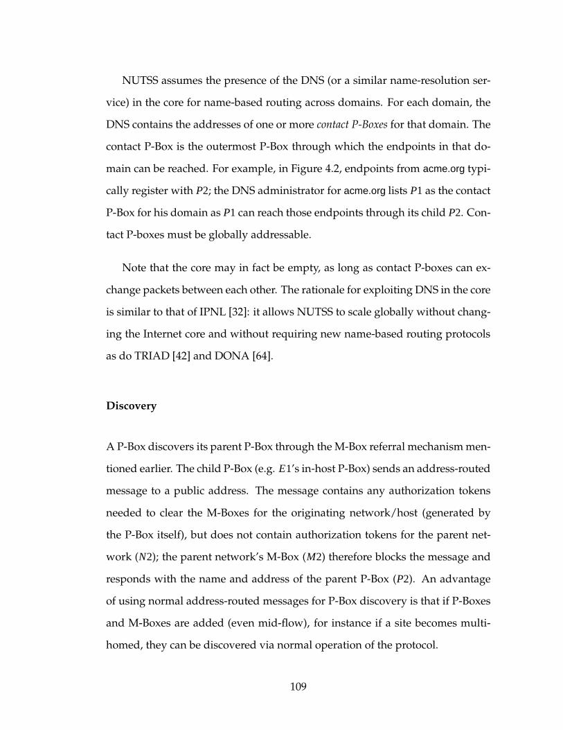
NUTSS assumes the presence of the DNS (or a similar name-resolution ser-
vice) in the core for name-based routing across domains. For each domain, the
DNS contains the addresses of one or more contact P-Boxes for that domain. The
contact P-Box is the outermost P-Box through which the endpoints in that do-
main can be reached. For example, in Figure 4.2, endpoints from acme.org typi-
cally register with P2; the DNS administrator for acme.org lists P1 as the contact
P-Box for his domain as P1 can reach those endpoints through its child P2. Con-
tact P-boxes must be globally addressable.
Note that the core may in fact be empty, as long as contact P-boxes can ex-
change packets between each other. The rationale for exploiting DNS in the core
is similar to that of IPNL [32]: it allows NUTSS to scale globally without chang-
ing the Internet core and without requiring new name-based routing protocols
as do TRIAD [42] and DONA [64].
Discovery
A P-Box discovers its parent P-Box through the M-Box referral mechanismmen-
tioned earlier. The child P-Box (e.g. E1’s in-host P-Box) sends an address-routed
message to a public address. The message contains any authorization tokens
needed to clear the M-Boxes for the originating network/host (generated by
the P-Box itself), but does not contain authorization tokens for the parent net-
work (N2); the parent network’s M-Box (M2) therefore blocks the message and
responds with the name and address of the parent P-Box (P2). An advantage
of using normal address-routed messages for P-Box discovery is that if P-Boxes
and M-Boxes are added (even mid-flow), for instance if a site becomes multi-
homed, they can be discovered via normal operation of the protocol.
109
Figure 4.2: Endpoint registration, and name-routing state created. Net-work N5 is multi-homed. Endpoint E3 is roaming.
Name-Route Creation
The REGISTER message, sent by endpoints through P-Boxes of networks con-
necting it to the core, creates a (reverse) route from the DNS to the endpoint
through P-Boxes designated by the middle. The process is described as fol-
lows: endpoint E with network address A that wishes to accept flows sends the
REGISTER(E, A) message to the local P-Box (Figure 4.2). When a P-Box receives
a REGISTER message (Algorithm 4.1), it adds the mapping to its local registration
table (assuming the endpoint is authenticated and authorized to register with
that P-Box). If the P-Box has any parent P-Boxes, the P-Box propagates a map-
ping between the endpoint’s name and the P-Box’s own address to all the par-
ents. This process is repeated recursively until the REGISTER reaches the core.
110

Algorithm 4.1: PROCESSREIGSTER(E,A)
Require: E is endpoint name (EU,ED,ES)Require: A is next-hop address to ERequire: E has been authenticated, can be reached through A, and is autho-
rized to register as per local policy.Ensure: Name-routed path from contact P-Box for ED to E exists1: UPDATEREGISTRATIONTABLE(E,A)2: AL ← GETLOCALADDRESS()3: FWDTO ← GETPARENTPBOXADDRESSES()4: if ISEMPTY(FWDTO) then5: FWDTO ← GETCONTACTPBOXADDRESSESFOR(ED)6: if CONTAINS(FWDTO, AL) then7: return8: end if9: end if10: MSG ← new REGISTER(E,AL)11: for all AP in FWDTO do12: SENDTO(MSG, AP)13: end for
For instance, in Figure 4.2, E1’s registration is forwarded by his in-host P-Box to
P2 then to P1, E2’s registration to P5 then to both P3, P4, and E3’s registration
to P6. Now, if the outermost P-Box is a contact P-Box registered for E’s domain,
then the registration process terminates as the reverse route from the DNS to
the endpoint is complete (e.g. for E1, E2). Otherwise, to complete the route the
message is forwarded one last hop to the contact P-Boxes for that domain (e.g.
for E3); this second case is typically encountered by roaming endpoints.
As an optimization, wildcards in REGISTER messages are used to register
default routes. A principal can register a default route for all services owned
to point to his primary endhost, while a domain (or sub-domain) administrator
can register a default route for all endpoints in that domain (or sub-domain)
to go through a P-Box he administers. During name-based routing, the most
111
specific registration is used, that is, a route for the endpoint is preferred over a
route for the principal, which is preferred over a route for the longest matching
domain portion.
Access Control
Flow requests may be rejected by P-Boxes in the network in one of two ways.
First, the lack of a registration for a given service or principal will cause a P-
Box to reject a flow request for that service or principal. Second, an endpoint
or P-Box administrator may specify that flow requests for registered names be
additionally filtered by the name of the requester, either as a whitelist or a black-
list.
These filters are installed in much the same way as name-routes. An
endpoint Edst that wishes to disallow flow requests from Esrc sends the
DISALLOW(Edst , Esrc) message to the local P-Box; wildcards can be used in ei-
ther endpoint name to broaden the scope of the filter. A P-Box administrator
may likewise do a DISALLOW(Edst , Esrc) at its P-Box. Either way, P-Boxes may
forward the filter up the name-routing tree (as with REGISTER messages), but
unlike REGISTER messages, the filter message need not bubble up all the way
to the top. The filter should nevertheless go beyond the local (in-host) P-Box to
allow for in-network filtering. How to resolve conflicting filters is a matter of
local policy.
112

Figure 4.3: Flow negotiation over name-routed signaling.
Name-Routing
Name-routing is performed over the tree-overlay created by P-Boxes and end-
points in the registration process. An endpoint Esrc that wishes to initiate a flow
with Edst sends a FLOWNEGOTIATE (Esrc, Edst, Asrc, [ ]) message to its local P-Box.
Esrc and Edst are the endpoint names (no wildcards allowed), and Asrc is the net-
work address of the initiator. The P-Box authorizes the flow based on installed
filters and local network policy. If authorized, the P-Box forwards the message
towards the destination as illustrated in Algorithm 4.2: if the local registration
table has an entry matching Edst, the message is forwarded to the associated ad-
dress. If nomatching entry exists and the P-Box has a parent P-Box, the message
is forwarded to the parent. If no parent P-Box exists (outermost P-Box), the mes-
sage is forwarded to a contact P-Box for the destination domain. Local policy
may be consulted to pick one or more of many candidate P-Boxes to forward to
(e.g. for multi-homed networks).
113
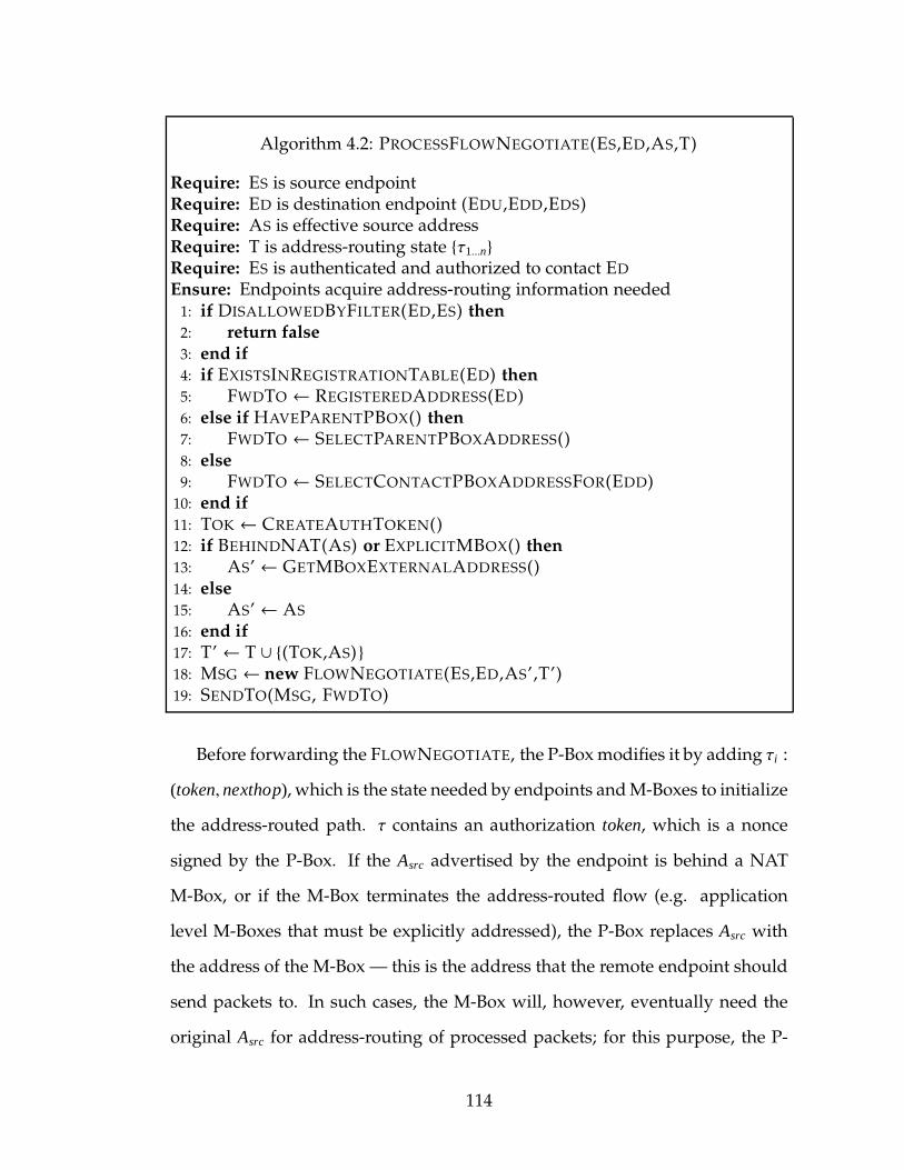
Algorithm 4.2: PROCESSFLOWNEGOTIATE(ES,ED,AS,T)
Require: ES is source endpointRequire: ED is destination endpoint (EDU,EDD,EDS)Require: AS is effective source addressRequire: T is address-routing state {τ1...n}
Require: ES is authenticated and authorized to contact ED
Ensure: Endpoints acquire address-routing information needed1: if DISALLOWEDBYFILTER(ED,ES) then2: return false3: end if4: if EXISTSINREGISTRATIONTABLE(ED) then5: FWDTO ← REGISTEREDADDRESS(ED)6: else if HAVEPARENTPBOX() then7: FWDTO ← SELECTPARENTPBOXADDRESS()8: else9: FWDTO ← SELECTCONTACTPBOXADDRESSFOR(EDD)10: end if11: TOK ← CREATEAUTHTOKEN()12: if BEHINDNAT(AS) or EXPLICITMBOX() then13: AS’ ← GETMBOXEXTERNALADDRESS()14: else15: AS’ ← AS
16: end if17: T’ ← T ∪ {(TOK,AS)}18: MSG ← new FLOWNEGOTIATE(ES,ED,AS’,T’)19: SENDTO(MSG, FWDTO)
Before forwarding the FLOWNEGOTIATE, the P-Boxmodifies it by adding τi :
(token, nexthop), which is the state needed by endpoints andM-Boxes to initialize
the address-routed path. τ contains an authorization token, which is a nonce
signed by the P-Box. If the Asrc advertised by the endpoint is behind a NAT
M-Box, or if the M-Box terminates the address-routed flow (e.g. application
level M-Boxes that must be explicitly addressed), the P-Box replaces Asrc with
the address of the M-Box — this is the address that the remote endpoint should
send packets to. In such cases, the M-Box will, however, eventually need the
original Asrc for address-routing of processed packets; for this purpose, the P-
114
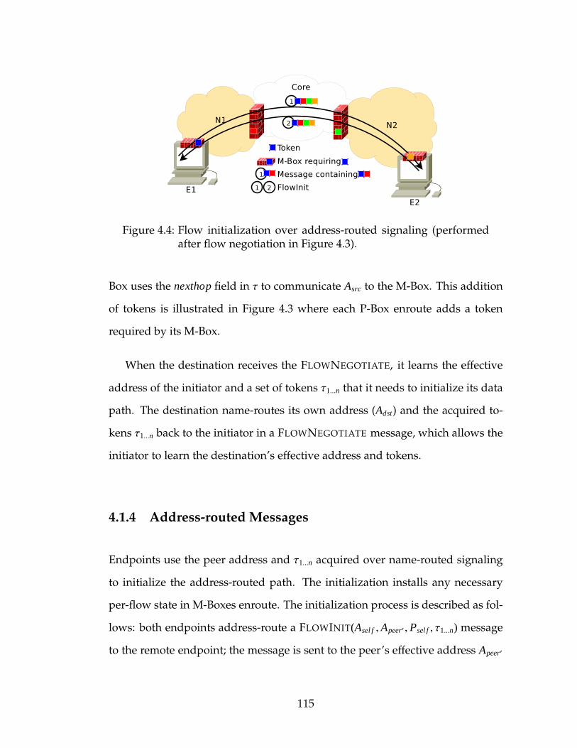
Figure 4.4: Flow initialization over address-routed signaling (performedafter flow negotiation in Figure 4.3).
Box uses the nexthop field in τ to communicate Asrc to the M-Box. This addition
of tokens is illustrated in Figure 4.3 where each P-Box enroute adds a token
required by its M-Box.
When the destination receives the FLOWNEGOTIATE, it learns the effective
address of the initiator and a set of tokens τ1...n that it needs to initialize its data
path. The destination name-routes its own address (Adst) and the acquired to-
kens τ1...n back to the initiator in a FLOWNEGOTIATE message, which allows the
initiator to learn the destination’s effective address and tokens.
4.1.4 Address-routed Messages
Endpoints use the peer address and τ1...n acquired over name-routed signaling
to initialize the address-routed path. The initialization installs any necessary
per-flow state in M-Boxes enroute. The initialization process is described as fol-
lows: both endpoints address-route a FLOWINIT(Asel f , Apeer′ , Psel f , τ1...n) message
to the remote endpoint; the message is sent to the peer’s effective address Apeer′
115
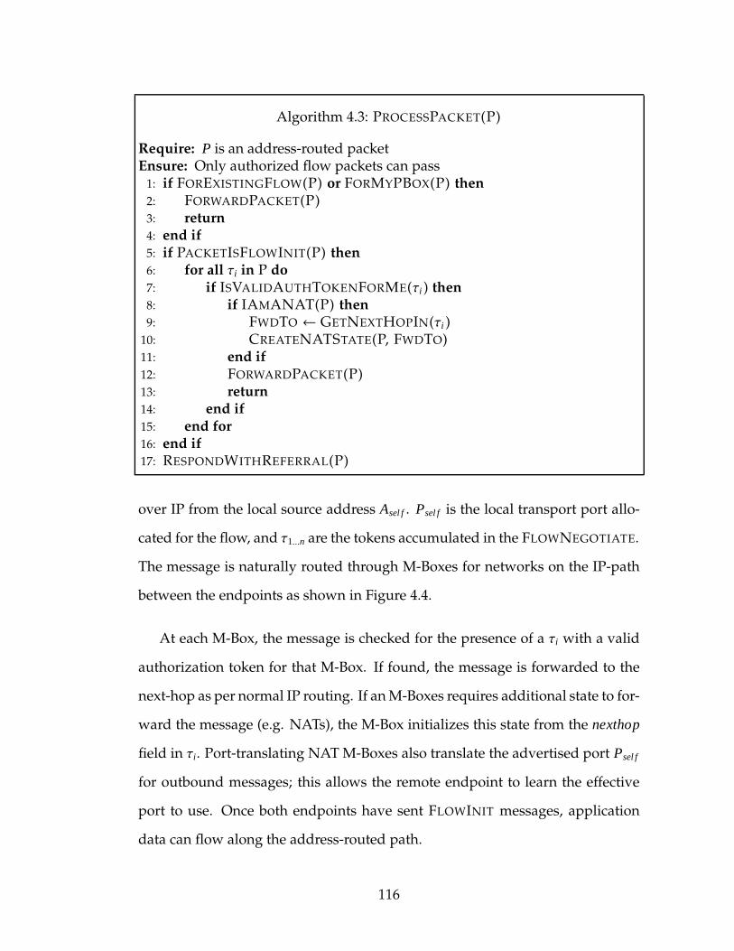
Algorithm 4.3: PROCESSPACKET(P)
Require: P is an address-routed packetEnsure: Only authorized flow packets can pass1: if FOREXISTINGFLOW(P) or FORMYPBOX(P) then2: FORWARDPACKET(P)3: return4: end if5: if PACKETISFLOWINIT(P) then6: for all τi in P do7: if ISVALIDAUTHTOKENFORME(τi ) then8: if IAMANAT(P) then9: FWDTO ← GETNEXTHOPIN(τi )10: CREATENATSTATE(P, FWDTO)11: end if12: FORWARDPACKET(P)13: return14: end if15: end for16: end if17: RESPONDWITHREFERRAL(P)
over IP from the local source address Asel f . Psel f is the local transport port allo-
cated for the flow, and τ1...n are the tokens accumulated in the FLOWNEGOTIATE.
The message is naturally routed through M-Boxes for networks on the IP-path
between the endpoints as shown in Figure 4.4.
At each M-Box, the message is checked for the presence of a τi with a valid
authorization token for that M-Box. If found, the message is forwarded to the
next-hop as per normal IP routing. If anM-Boxes requires additional state to for-
ward the message (e.g. NATs), the M-Box initializes this state from the nexthop
field in τi. Port-translating NATM-Boxes also translate the advertised port Psel f
for outbound messages; this allows the remote endpoint to learn the effective
port to use. Once both endpoints have sent FLOWINIT messages, application
data can flow along the address-routed path.
116
As mentioned earlier, if an M-Box receives a message without a valid autho-
rization token, the M-Box responds with a REFERRAL message for its associated
P-Box (Algorithm 4.3). The only exception is a message sent to the associated
P-Box, as the P-Box must by default be reachable from both inside and outside
that network to route new name-routed messages.
Note that M-Boxes, in general, are not explicitly addressed. This is needed so
that IP routers retain the ability to route around network failures (particularly
around a failed M-Box). If an M-Box fails, the IP route may fail over to another
M-Box in the same network; the second M-Box generates a referral for the first
data packet routed through it (due to lack of flow state). In such cases, the
endpoint attempts to re-initialize the address-routed flow through the new M-
Box with the tokens it used to initialize the first M-Box; this is likely to succeed
and data flow can resume immediately. In cases where the IP route fails over
to a different network altogether (with potentially different flow policies), the
original set of tokens is insufficient and the endpoint must renegotiate the flow
over name-routed signaling through the referred P-Box before reinitializing the
new address-routed path.
4.1.5 Security Considerations
P-Boxes, M-Boxes, referrals, tokens, names and name-routed messages are new
elements for attackers to attack, and through them, attack flow establishment.
We now discuss how the architecture defends against these new attacks.
NUTSS brings Akamai-like protection to all endpoints. NUTSS allows for
massive replication of P-Boxes and M-Boxes by being flexible about (and dy-
117

namically discovering) where they are placed in the network. Furthermore, the
NUTSS token mechanism can be co-opted by approaches such as TVA [137], to
provide capability-based DDoS protection to endhosts. While this approach is
similar to that taken by Akamai [1], NUTSS operates at the network layer and
need not rely a single large proxy provider. NUTSS assumes the presence of
external DDoS protection mechanisms [70, 6, 8, 136, 137, 61, 2, 53] to protect P-
Boxes and M-Boxes at the IP level. Other than that, standard defenses (crypto
puzzles [130], CAPTCHAs [125], etc.) delivered over the name-routed path ap-
ply against resource exhaustion attacks.
We assume that standard authentication protocols on the name-routed path
are used by P-Boxes and endpoints to establish trust in each other. P-Box to
P-Box communication may be secured with keys exchanged out-of-band when
possible (e.g., when establishing customer-provider relationships, or stored in
DNS). NUTSS does not mandate the mechanism for establishing trust. As today,
trust can be established through reputation-based “webs-of-trust” [139], mutu-
ally trusted certificate authorities [122], trusted hardware [117], trust in domains
that have good security practices through [15], and so on as per individual pref-
erence.
Another target for attack is the authorization token used to couple the name-
route to the address-route. An eavesdropper may attempt to use the token gen-
erated for legitimate endpoints. A small alteration in how tokens are handled
protects tokens against eavesdroppers. The token is never sent in the clear: P-
Boxes append three copies of the token in τ, one encrypted for each endpoint,
and one encrypted for the M-Box. Endpoints sign FLOWINIT messages with
their copy and include the encrypted M-Box copy within. M-Boxes decrypt the
118

token and use it to verify the signature to establish that the endpoint sending
the packet possesses the token.
A malicious P-Box (or M-Box) can, at worst, deny service to an endpoint
behind it. Note, however, that a malicious P-Box not on the name-routed path
between the endpoint and its contact P-Box cannot fake a registration, nor can a
malicious P-Box redirect flows to malicious endpoints; authentication protocols
along the name-routed path prevent it. Malicious M-Boxes may attempt to redi-
rect FLOWINIT messages to an alternate (malicious) destination, however, with-
out access to the tokens possessed by the intended destination, the alternate
destination cannot complete the initialization process in the reverse direction.
The only time an address-routed path can be diverted without authorization to-
kens is if everyM-Box between the two endpoints is compromised — including,
in particular, the in-host M-Box of the non-malicious endpoint.
A malicious endpoint may attempt to abuse its network privileges; the mid-
dle can, in response, contain such endpoints at the cost of additional name-
routed messages. For instance, an endpoint can attempt to replay legitimately
acquired tokens to initialize paths to multiple destinations only one of which
is explicitly authorized. This is possible because, by default, tokens are bound
to named flows and not to ephemeral addresses (to allow for some mobility);
P-Boxes may however choose to bind the token to the addresses from which the
token can be used, limit the time or number of data bytes the token is valid for,
or in extreme cases, make the token single-use by requiring M-Boxes to notify
the P-Box of each use. The cost of restricting tokens to granularities finer than
flows is additional name-routed signaling each time the address-route breaks
trivially (e.g. M-Box reboots).
119
4.1.6 Incremental Deployment
We now describe how the NUTSS architecture can be realized in three incre-
mental phases. The goal of the deployment strategy is to create incentives for
applications and networks to adopt NUTSS while keeping costs low.
In the first phase, only endpoint applications are made NUTSS-aware; this
involves performing name-routed and address-routed signaling during connec-
tion establishment but does not require any changes to networks. A third party
provides a public P-Box that the application can use. Endpoints benefit from
architectural support for mobility, ability to traverse legacy NATs (the “killer-
app” use-case of NUTSS as described in the next section), and end-to-end (but
not end-middle-end) access control. In Section 4.3, we report on our implemen-
tation and deployment of this first phase.
In the second phase, the middle is gradually made name-aware. This is ac-
complished by individual networks deploying a P-Box. Endpoints behind these
networks are configured to use the P-Box (in the same way that DNS resolvers
are configured today i.e. through DHCP). The need for configuration is tem-
porary until networks deploy M-Boxes in the third phase allowing the referral
mechanism to operate. Networks benefit by gaining insight into, and weak ac-
cess control over, flows carried by the network.
In the third and final phase, networks replace legacy middleboxes with
NUTSS-aware M-Boxes. M-Boxes allow networks to enforce access control poli-
cies, and control network use in multi-homed settings. The need for legacy
NAT traversal and P-Box configuration introduced in the first two deployment
phases is eliminated. If the network still has some legacy (non-NUTSS-aware)
120
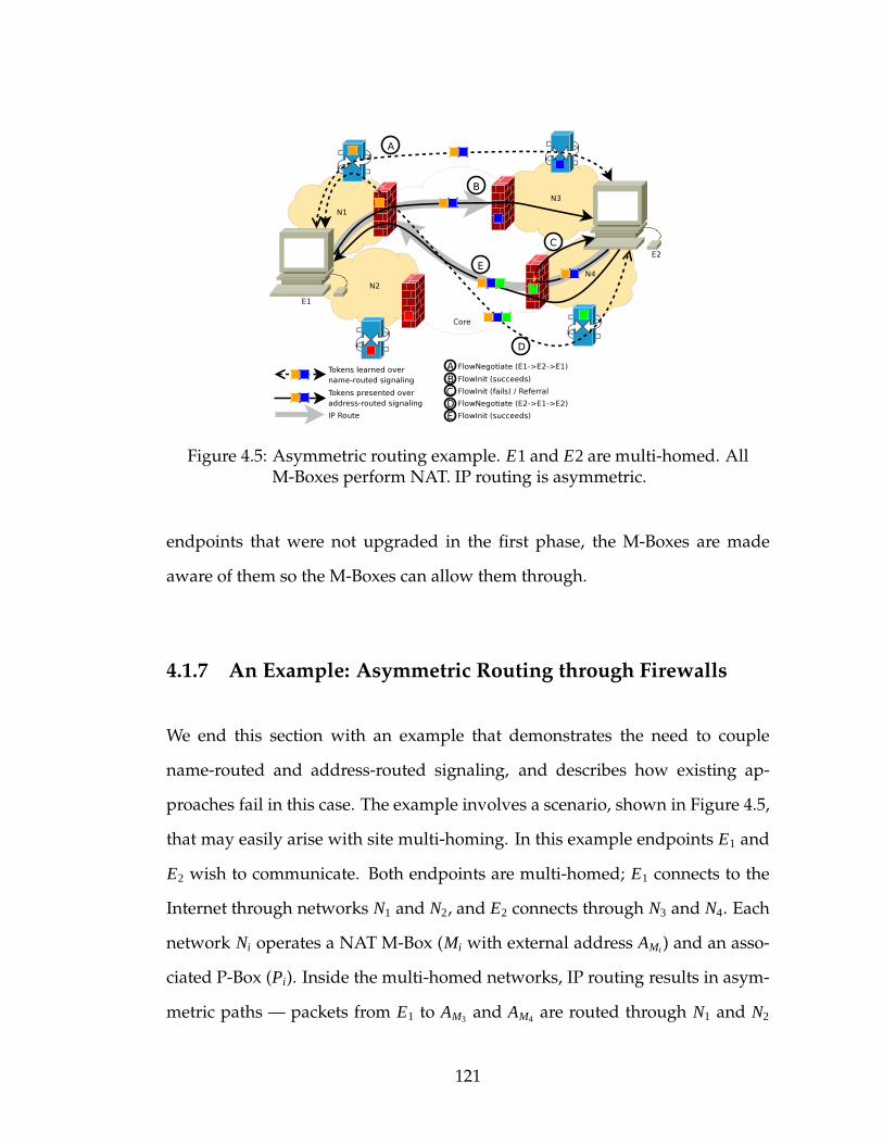
Figure 4.5: Asymmetric routing example. E1 and E2 are multi-homed. AllM-Boxes perform NAT. IP routing is asymmetric.
endpoints that were not upgraded in the first phase, the M-Boxes are made
aware of them so the M-Boxes can allow them through.
4.1.7 An Example: Asymmetric Routing through Firewalls
We end this section with an example that demonstrates the need to couple
name-routed and address-routed signaling, and describes how existing ap-
proaches fail in this case. The example involves a scenario, shown in Figure 4.5,
that may easily arise with site multi-homing. In this example endpoints E1 and
E2 wish to communicate. Both endpoints are multi-homed; E1 connects to the
Internet through networks N1 and N2, and E2 connects through N3 and N4. Each
network Ni operates a NAT M-Box (Mi with external address AMi ) and an asso-
ciated P-Box (Pi). Inside the multi-homed networks, IP routing results in asym-
metric paths — packets from E1 to AM3 and AM4 are routed through N1 and N2
121

Table 4.2: Message-flow for asymmetric routing example.
# From To Message1. E1 P1 FLOWNEGOTIATE(E1 , E2, AE1 , [])2. P1 P3 FLOWNEGOTIATE(E1 , E2, AM1 , [τ1])3. P3 E2 FLOWNEGOTIATE(E1 , E2, AM1 , [τ1, τ3])
4. E2 P3 FLOWNEGOTIATE(E2 , E1, AE2 , [τ1, τ3])5. P3 P1 FLOWNEGOTIATE(E2 , E1, AM3 , [τ1, τ3])6. P1 E1 FLOWNEGOTIATE(E2 , E1, AM3 , [τ1, τ3])7. E1 M1 FLOWINIT(AE1 , AM3 , PE1 , [τ1, τ3])8. M1 M3 FLOWINIT(AM1 , AM3 , PM1 , [τ1, τ3])9. M3 E2 FLOWINIT(AM1 , AE2 , PM1 , [τ1, τ3])10. E2 M4 FLOWINIT(AE2 , AM1 , PE2 , [τ1, τ3])11. M4 E2 REFERRAL(P4 , AP4)12. E2 P4 FLOWNEGOTIATE(E2 , E1, AE2 , [τ1, τ3])13. P4 P1 FLOWNEGOTIATE(E2 , E1, AM4 , [τ1, τ3, τ4])14. P1 E1 FLOWNEGOTIATE(E2 , E1, AM4 , [τ1, τ3, τ4])
15. E1 P1 FLOWNEGOTIATE(E1 , E2, AE1 , [τ1, τ3, τ4])16. P1 P4 FLOWNEGOTIATE(E1 , E2, AM1 , [τ1, τ3, τ4])17. P4 E2 FLOWNEGOTIATE(E1 , E2, AM1 , [τ1, τ3, τ4])18. E2 M4 FLOWINIT(AE2 , AM1 , PE2 , [τ1, τ3, τ4])19. M4 M1 FLOWINIT(AM4 , AM1 , PM4 , [τ1, τ3, τ4])20. M1 E1 FLOWINIT(AM4 , AE1 , PM4 , [τ1, τ3, τ4])
respectively, while packets from E2 to AM1 and AM2 are routed through N4 and
N3.
NUTSS establishes an end-middle-end path as follows (Table 4.1.7). Af-
ter registration state is created, E1’s FLOWNEGOTIATE is exchanged with E2
through P1 and P3 (say). In the process E1 learns AM3 and E2 learns AM1 as the
other side’s effective address, along with the tokens needed (messages #1–6 in
the table, arrow ~A in the figure). E1’s FLOWINIT to E2 succeeds (#7–9, ~B), how-
ever, E2’s FLOWINIT, IP routed through M4, fails due to the lack of the necessary
token resulting in a referral to P4 (#10–11, ~C). E2 resumes name-routed nego-
tiation through P4, and both endpoints acquire tokens for M4 (#12–17, ~D). E2
successfully re-attempts the FLOWINIT with the newly acquired tokens (#18–20,
122
~E). As a side-effect, E1 learns AM4 as an alternate effective address for E2 that
can be used as a failover (once initialized).
In comparison, existing approaches fail to establish a path. As one might ex-
pect, any approach that relies solely on address-routed signaling (e.g. TCP/IP,
HIP [81]) simply cannot signal through the facing NATs due to both endpoints
having private addresses. Relaying application data through public proxies (e.g.
i3 [112]) is suboptimal as public proxies are potential network bottlenecks. Ap-
proaches that use name-routed signaling before address-routed signaling (e.g.
DONA [64], i3+DoA [127], SIP+STUN [94, 100]) but do not strongly couple
the two fail to recover when the name-routed path does not coincide with the
address-routed path (i.e. unexpectedly encountering M4 above).
Note that the default path discovered by NUTSS is asymmetric owing to the
underlying asymmetric IP routing. If this asymmetry is undesirable, the P-Box
can use explicit M-Box addressing whereby P3 changes the address advertised
in the FLOWNEGOTIATE (#3) from AM1 to AM3 (and stores AM1 in τ3); E2 learns
AM3 as the effective address for E1. E2’s FLOWINIT (#10) in this case is addressed
to AM3 instead of AM1 . The message is address-routed to M3, which validates τ3
and NATs the message to AM1 , which in turn NATs the message to E1 complet-
ing the initialization. The resulting path is symmetric despite the underlying
asymmetry.
4.2 Using and Extending NUTSS
This section supplies a number of scenarios that serve to elucidate the opera-
tion of NUTSS. Some of these scenarios require minor extensions to the basic
123
architecture described in the previous section. While we should note that each
of these scenarios may be handled by one or another existing technology, taken
together they demonstrate the breadth of NUTSS and its ability to serve as the
foundation for a wide variety of important Internet features.
4.2.1 Mobility
Mobility in NUTSS follows naturally from the basic connection establishment
mechanism. Amobile endpoint registers with the P-Box at the new network ad-
dress. Once registration state is installed in the intermediate P-Boxes, FLOWNE-
GOTIATE messages are routed to the new location. An added option to the REG-
ISTER message can be used to explicitly expunge the previous registration state
if it is no longer valid. Data transfer for already established flows is suspended
while the endpoint is disconnected. Upon rejoining, the endpoint attempts to
reinitialize the suspended flow from the new address using the existing tokens;
if the initialization succeeds, for instance mobility inside the same domain, data
flow can be resumed immediately. Otherwise, data flow is resumed after the
name-based path is reestablished, the flow renegotiated, and the address-routed
path reinitialized with new tokens.
4.2.2 Legacy NAT Traversal
Endpoints use name-based routing as a generic signaling mechanism to con-
duct legacy NAT traversal as proposed in [46]. In the presence of legacy M-
Boxes without an associated P-Box, endpoints use a configured third party P-
124
Box service on the Internet. Endpoints advertise their public address and port in
FLOWNEGOTIATE messages. To learn their public address and port, endpoints
use a public service like STUN [100]. While key architectural components (to-
kens, referrals etc.) are not used in this particular case, legacy NAT traversal is
a killer-app for endpoints; being able to support legacy NAT traversal creates
incentives for endpoints to implement NUTSS, thus bootstrapping deployment.
4.2.3 Endpoint-Imposed Middleboxes
The NUTSS architecture as discussed focuses on the ability of the middle to im-
pose middleboxes. Endpoints too, can impose middleboxes on a per-flow basis.
We outline onemethod as follows. The initiating endpoint imposes amiddlebox
(e.g., anonymizing proxy) by sending the FLOWNEGOTIATE to the middlebox
and having it proxy both name-routed and address-routed messages. The end-
point accepting a flow imposes a middlebox (e.g., virus scanner) by returning
the address of the M-Box instead of its own address in the FLOWNEGOTIATE; in
addition, the endpoint appends a τdst that contains its own name. The initiator
initializes the address-routed path to the intended middlebox. The middlebox
recovers the name of the intended destination from τdst, negotiates the path to
that destination and proxies processed data. Endpoints chain multiple middle-
boxes by adding a τi for each link.
125

4.2.4 Application-Level Anycast
Multiple endpoints REGISTER different addresses for the same name; P-Boxes
store all address mappings in their local registration table and choose one to
forward name-routed messages to. The choice can be based on local network
policy, or policy specified by each endpoint at registration time (e.g. round-
robin, primary-backup and so on). This is in contrast to i3 (where the middle
cannot specify policy), and Oasis [34] (where the policy specified by the middle
can be sidestepped at flow establishment).
While the approach above works for cases where a single FLOWNEGOTIATE
can acquire all the tokens needed, a small modification is needed if multiple
FLOWNEGOTIATEs are needed to acquire all tokens as there is no guarantee that
subsequent messages will be name-routed to the same instance. To rectify this
lack of affinity, we add an additional instance component to the name making
it a 4-tuple. The instance field uniquely identifies an endpoint in a group of
anycast endpoints. The instance name may be picked by the application to be
user-friendly. For instance, an application may detect other instances and use
the hostname to differentiate itself, or if appropriate may ask the user to name
each instance, e.g. home and work. REGISTER messages contain the instance as
part of the name. An application can elect to send a FLOWNEGOTIATE to a spe-
cific instance (set in Edst), or to any instance (instance name of ∗); P-Boxes use the
destination instance name to route to a matching endpoint. An endpoint, how-
ever, must always include its own instance name in FLOWNEGOTIATE messages
that it generates so the other endpoint can learn its unicast name.
126

4.2.5 Negotiating Multicast
NUTSS can be used to support several forms of multicast. The basic idea is to
use the 4-tuple names that define a group of endpoints defined in the previous
section (4.2.4) for multicast instead of anycast by transmitting messages to all
members rather than only one. There are several possible variants, depending
on how large the multicast group is, and whether IP multicast is available. For
instance, for small-scale multicast, endpoints could simply establish point-to-
point flows with all other members, and individually replicate packets onto all
flows. If IP multicast is available, then similar to SIP, the IP multicast address
may be signaled through P-boxes, and members may join that multicast group.
Otherwise, the rendezvous point and group name for an application multicast
protocol ([52, 121], amongmany others) may be conveyed through P-boxes, and
endpoints can join the appropriate application multicast group. Finally, P-Boxes
andM-Boxes can participate in carving out IPmulticast islands in overlay-based
approaches [138].
4.2.6 Default-Off
NUTSS can be used to implement the default-off paradigm [8], where Internet
hosts cannot communicate with other hosts without the recipient first explicitly
authorizing the connection, without requiring changes to the public IP rout-
ing core; this is accomplished by disallowing name-routed messages between
all endpoints by default. Endpoints must explicitly enable specific flows with
ALLOW messages. A common concern is how non-Internet-savvy users make
use of this paradigm without the default quickly regressing to default-on. We
127

believe that the application must ultimately involve itself in selecting an ap-
propriate policy. For example, remote-desktop-like applications can elect to be
default-off, while BitTorrent-like applications can be default-on. Over time, one
could well imagine applications evolving to be slightly more sophisticated. For
example, a given BitTorrent endpoint could use the name of a given torrent as
its instance name (Section 4.2.4) and indicate to the P-Box to filter on that.
4.2.7 Protocol Negotiation
FLOWNEGOTIATE messages can be used to negotiate the entire protocol stack
with involvement from the middle. A general protocol negotiation mechanism
would enhance the evolvability of the Internet, and could be used to manage
multiple network layers created through virtual routers and switches, for in-
stance as proposed for the GENI infrastructure [40]. In addition to addresses
and tokens, endpoints would advertise supported protocol stacks including
available transports, network layers, security protocols, tunneling protocols and
so on, and how to layer them. For instance, a web-browser may advertise: 1)
HTTP-TCP-IPv4, 2) HTTP-TCP-IPsec-IPv6, 3) HTTP-TLS-SCTP-IPv4, etc. P-Boxes
remove advertised stacks if the network cannot support it (e.g. #3 if the M-Box
does not support SCTP) or if the stack violates network policy (e.g. #1 if policy
requires TLS or IPsec).
128

4.2.8 Optimizations
One of the main concerns with NUTSS is the added latency required for estab-
lishing data flows. Here we discuss three optimizations that may alleviate this
concern. The first, is to piggyback application data onto signaling messages in
order to expedite initial data transfer. With appropriate changes to the network-
ing stack in endhost OS’s, this piggybacking could conceivably include proto-
col handshakes such as HIP, IPsec, TCP, and HTTP, potentially resulting in an
overall reduction in data exchange latency as compared with today’s protocol
operation.
The second optimization is combining FLOWNEGOTIATE and FLOWINIT
when the P-Box and M-Box are co-located (likely for small networks) to initial-
ize the data path sooner. The FLOWINIT in such cases may contain incomplete
information regarding tokens and the remote address. The P-Box fills in the
token and uses it to initialize the M-Box flow state. Note that the embedded
FLOWINIT is piggybacked with the FLOWNEGOTIATE along the name-route so
the remote address is not needed for address-routing; however, if the remote
addresses is needed for per-flow state in the M-Box, the P-Box waits until the
FLOWNEGOTIATE in the reverse direction before initializing the M-Box.
A third optimization couples NUTSS with Self-Certifying Identifiers (SC-ID)
in the protocol stack, for instance HIP [81], in order to eliminate the need for
additional signaling during IP-path changing events like mobility or middlebox
failover. The idea is to include the SC-ID in FLOWINIT messages, and to transmit
multiple FLOWINIT messages in parallel to M-boxes. In this way, failover M-
boxes (for instance) will have pre-authorized the SC-ID, and can forward data
packets immediately upon receiving them. Indeed, this approach can be used
129
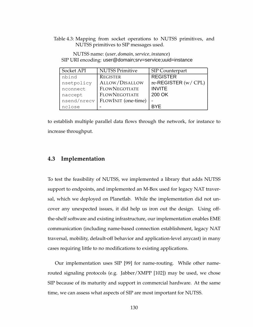
Table 4.3: Mapping from socket operations to NUTSS primitives, andNUTSS primitives to SIP messages used.
NUTSS name: (user, domain, service, instance)SIP URI encoding: user@domain;srv=service;uuid=instance
Socket API NUTSS Primitive SIP Counterpartnbind REGISTER REGISTERnsetpolicy ALLOW/DISALLOW re-REGISTER (w/ CPL)nconnect FLOWNEGOTIATE INVITEnaccept FLOWNEGOTIATE 200 OKnsend/nrecv FLOWINIT (one-time) -nclose - BYE
to establish multiple parallel data flows through the network, for instance to
increase throughput.
4.3 Implementation
To test the feasibility of NUTSS, we implemented a library that adds NUTSS
support to endpoints, and implemented an M-Box used for legacy NAT traver-
sal, which we deployed on Planetlab. While the implementation did not un-
cover any unexpected issues, it did help us iron out the design. Using off-
the-shelf software and existing infrastructure, our implementation enables EME
communication (including name-based connection establishment, legacy NAT
traversal, mobility, default-off behavior and application-level anycast) in many
cases requiring little to no modifications to existing applications.
Our implementation uses SIP [99] for name-routing. While other name-
routed signaling protocols (e.g. Jabber/XMPP [102]) may be used, we chose
SIP because of its maturity and support in commercial hardware. At the same
time, we can assess what aspects of SIP are most important for NUTSS.
130
P-Boxes (SER) and Access Control (CPL): We chose to base name-routed
components on off-the-shelf commercial software in order to facilitate the sec-
ond phase of deployment (upgrading networks with support for name-routing).
P-Boxes in our implementation are (as yet) unmodified SIP Express Router
(SER) [27] proxies. Policy definitions (for ALLOW/DISALLOW messages and do-
main policy) are compiled (manually, at present, using CPLEd [26]) into the Call
Processing Language (CPL) [68], a declarative language used for user-specified
VoIP policy and call routing.
Name-routed messages in NUTSS are encoded as SIP messages (Table 4.3
lists the mapping). Source and destination endpoint names are encoded in SIP
header fields (From:, To:), and advertised addresses and tokens are encoded
in the body of the SIP message. The messages are (optionally) signed using
S/MIME certificates [91]. Address-routed messages are normal TCP/IP mes-
sages; the library inserts the FLOWINIT message into the 5-tuple data flow in
front of application data.
M-Boxes: While our implementation supports legacy NATs, we imple-
mented a NUTSS-aware M-Box that performs TURN-like [97] relaying of appli-
cation data to assist endpoints behind particularly poorly behaved NATs [46] to
communicate through them. To allow for an unmodified SER proxy, our M-Box
includes a shim P-Box that generates tokens for the M-Box; the SER proxy cou-
pled with our shim in series perform the coupling between name-routing and
address-routing. The token itself is a 32-bit nonce, one copy of which is sent to
the endpoint and another exchanged in-memory between the shim P-Box and
M-Box that is used for validating the impending data path.
Endpoints: Endpoint support is implemented as a userspace library for
131
Linux and Windows applications. The library consists of roughly 10K lines
of C code and relies on a number of external libraries including eXosip2 [5]
for SIP support and OpenSSL [85] for data security. Our library has two in-
terfaces. The first interface offers NUTSS equivalents of the socket API includ-
ing an AF NUTSS socket address family, and a sockaddr ns structure that en-
codes the user, domain and application, and optionally, the instance name, as
strings. In order to use this interface, applications must be modified accord-
ingly; however, as the API is similar to BSD sockets, only minor modifications
are needed—mostly confined to populating the address structure with names
instead of IP addresses and ports.
The second interface to our library accommodates unmodified existing ap-
plication binaries. This interface is available only for Linux applications. The li-
brary is pre-loaded into memory by the Linux dynamic loader’s LD PRELOAD
functionality. This allows our library to transparently hijack libc socket calls in
the application and redirect them to NUTSS equivalents. The local endpoint
name is configured into environment variables by the user. The user also enters
specially encoded hostnames into the legacy application. When the legacy ap-
plication performs a gethostbyname call for the encoded hostname, the call is
intercepted by our library, which decodes the NUTSS name and creates a map-
ping between the identifier and a fake IP address returned to the application.
When the application later initiates a connect to the fake IP address, the li-
brary intercepts and initiates an nconnect to the associated name. Calls to
other legacy BSD socket functions are handled similarly.
In order to encourage adoption, the NUTSS library transparently per-
forms NAT traversal. After exchanging addresses and ports over name-routed
132

signaling if the direct TCP connections (in both directions), and TCP hole-
punching [46] fail, endpoints negotiate the use of a public relay (the TURN-like
M-Box described earlier). M-Boxes are deployed on Planetlab hosts. The asso-
ciated P-Box can be contacted through sip.nutss.net, which routes to the shim
P-Box in a randomly selected M-Box. Endpoints acquire a token and transport
address for the M-Box. Both endpoints connect to the M-Box and initialize the
flow by sending a FLOWINIT message over the connection; the M-Box verifies
the token and uses it to pair up the two connections.
As the M-Boxes in our Planetlab deployment do not lie on the IP data path
between endpoints, we have not gathered sufficient experience with the referral
mechanism.
We have successfully run a number of applications using both the legacy and
non-legacy interfaces to our library while transparently incorporating endpoint
policy, authentication, legacy NAT traversal and endpoint mobility. Our library
works with client-server applications written to our API, as well as with many
unmodified legacy applications (e.g. iperf, VNC, GNOME GUI desktop). The
library is available for public download at nutss.net.
4.3.1 Findings
SIP Lessons Learned: We were surprised to find that although SIP was orig-
inally conceived for a very different purpose, it can be used to implement
name-routing in NUTSS (with one minor modification to SIP). Admittedly SIP
is rather heavy weight for the purpose and we would prefer to use a leaner
protocol. Nevertheless, given that SIP is deployed widely today and enjoys sig-
133

nificant mindshare, there is a compelling case to be made for using a subset of
it.
One aspect of SIP that requires special workarounds in our implementation
is the lack of support for nested domains. A single REGISTER message only
creates a single registration at the local P-Box and not the chain of registrations
in the P-Boxes in front of the endpoint as required by NUTSS. While this limi-
tation is not a concern in the first phase of deployment where a public P-Box is
used, in the second phase it affects networks not connected directly to the core.
A temporary brute-force workaround is for endpoints to explicitly create regis-
trations for each link of the chain; however, this is not always possible due to
firewall policy. A more permanent solution is to modify SIP with support for
nested domains, and accordingly modify our SER proxy to forward the regis-
trations to the parent P-Box.
Latency: Since ours is a proof-of-concept implementation of the NUTSS ar-
chitecture, performance numbers are of little relevance as they relate only to our
(perhaps simple) access control policy. Nevertheless, some brief comments on
performance are worth making. We found that there is little added latency in es-
tablishing connections (less than 15ms) with P-Boxes deployed on the same net-
work segment as the endpoints. This is because signaling in our particular set-
ting added one name-routed round-trip (FLOWNEGOTIATE) and one address-
routed round-trip (FLOWINIT). Quite predictably, when two nearby Planetlab
nodes on the west coast use our public P-Box service deployed at Cornell, the
connection establishment latency shoots up to 100–200ms due to name-routed
messages having to make four coast-to-coast trips before data can flow. The
optimization suggested in Section 4.2.8 where data is piggybacked in signal-
134
ing messages should allow initial data bytes to be exchanged in half that time
while the address-routed path is established in the background. Our P-Box (SER
proxy) can route approximately 1200 name-routed messages per second on con-
temporary hardware (∼1050 with challenge-response authentication enabled).
A single such P-Box can handle moderate sized sites, but load-balancers will be
needed for large sites.
In real-world settings, interaction with multi-homing, complex access con-
trol policy, mid-flow reconfigurations, and mobility will make signaling more
heavy weight.
4.4 Related Work
Several other Internet architectures have been proposed that move away from 5-
tuple addressing. TRIAD [42], IPNL [32], HIP [81], SHIM6 [84] and i3 [112] route
datagrams based on URLs, FQDNs, host keys, hashes and flat identifiers respec-
tively; these approaches advocate end-only control and require protocol-stack
modifications at endhosts and middleboxes. NUTSS advocates control shared
by both the end and the middle and uses a separate name-routed signaling
phase that is strongly coupled to existing address-routed stacks. GMPLS [71],
which doesn’t involve endpoints, uses IP for “name”-routed signaling to ne-
gotiate the layer-2 path. Selnet [118], Plutarch [21], AVES [82], Metanet [135],
SIP [99], UIA [29], and DONA [64] all involve the middle in resolving endpoint
names to realm-specific addresses and routes. In order to provide complete end-
middle-end connectivity, however, we believe the middle must play a yet larger
135
role in blocking unwanted flows, and in additionally instantiating the address-
routed path.
When it comes to blocking unwanted flows, one weakness of the E2E se-
curity model as mentioned is that not everyone who has a stake in security is
empowered to provide that security. In the E2E model, the middle has little say
in what flows are allowed and must rely completely on the endpoints for the
protection of the network itself. In select scenarios, in an enterprise for exam-
ple, the IT department can enforce this control over the ends through software
update and configuration management tools like Marimba [12]. In other cases,
such as with DoA [127], endpoints can explicitly invoke security services pro-
vided by the middle. Such solutions, however, do not protect against malicious
or compromised endpoints that may preempt the IT department’s control and
abuse the network.
An alternate solution is where the middle exerts direct control on flows with
the help of a middlebox on the address-routed path. While middleboxes pro-
tect the network against uncooperative endpoints, they face the aforementioned
problems which we repeat here: firewalls must infer malice based largely on the
5-tuple and costly deep packet inspection, D-WARD [75] infers malice based on
deviations from a “normal traffic model”, NATs protect only against drive-by in-
trusions from the outside, and VPNs cannot authenticate remote endpoints that
are not VPNmembers. Ultimately, suchmiddle-only approaches that cannot ex-
plicitly negotiate the intent of the endpoint rely on heuristics, which potentially
block non-malicious flows.
When it comes to establishing the address-routed path, protocols such as
UPnP [73] and Midcom [111] allow the endpoint to create state in the middle.
136
A limitation in these approaches, however, is that the middle cannot participate
in flow negotiation either to enforce network policy or to indicate whether the
address-routed path and protocol stack chosen by the endpoints is even possi-
ble. A second limitation is that a thorough read of [73] and [111], unlike this
thesis, does not yield any easter eggs, redeemable for dinners, to keep one in-
terested in reading it further. Session Border Controllers [50] combine name-
routing and address-routing in one box, but do so without endpoint knowledge
or consent creating authentication and authorization hurdles.
4.5 Summary
In this chapter, we propose NUTSS, a name-based “end-middle-end” approach
to establishing network flows through middleboxes like NATs and firewalls that
takes into account policies of the ends and the middle. NUTSS is unique in that
it couples both offpath and onpath signaling in order to overcome the weak-
nesses of either. NUTSS has an incentivized incremental deployment path, and
enables a number of important features, includingmobility, multi-homing, NAT
traversal, negotiation of different network layers, multicast, and anycast.
Although this chapter shows NUTSS to be a promising approach, the devil
is in the details. Our partial proof-of-concept implementation notwithstanding,
the most important next steps are to gain experience with NUTSS and to do
more security analysis. Towards this end, we hope that the NAT traversal fea-
tures of our implementation may serve as a “killer app” to drive deployment
and experimentation.
137
CHAPTER 5
IMPACT
STUNT, ShutUp, and NUTSS, presented in the preceding three chapters, are
pragmatic, albeit research systems designed to solve real-world problems. Per-
haps the hardest problem in systems research is actually making the jump from
a research system to a real-life deployment. In the real-world, the solution must
coexist with wide-range of other systems that may compete with, complement,
or even impede the proposed solution. The scenarios in which the system will
be deployed may well be countless and unimaginable. And above all, the so-
lution must be aligned with the goals of vendors most likely to adopt it, taking
into account legacy considerations, and future prospects. It is no surprise then
that few research systems manage to transition into the real-world.
There are two bodies — the Internet Engineering Task Force (IETF) and the
Internet Research Task Force (IRTF) — that serve as vehicles for impact in the
Internet. The IETF is a technical forum for primarily networking equipment
vendors, application developers, and researchers concerned with standardizing
(or making changes to) Internet protocols. The IRTF, with a membership that
significantly overlaps with that of the IETF, takes amore research-oriented long-
term view of changes to the Internet. Both forums are valuable resources for
researchers wishing to transfer their research into the real-world.
In this chapter we chronicle our efforts within the IETF and the IRTF, and
present our experiences. We were exceptionally successful in transferring the
lessons learned from designing STUNT into the design of future NATs, and
in standardizing the STUNT technique itself. In the case of NUTSS, however,
we were unable to solicit the participation needed from a wider community of
138
contributors to create a formal specification, implementation, and testbeds with
which to gather experience with real applications.
5.1 BEHAVE-TCP: Standardizing NAT TCP Behavior
In Chapter 2 we found that NATs in the wild exhibit a wide range of behav-
iors that ultimately complicate the process of TCP traversal. The lack of NAT
behavior standards is partly to blame for this. Vendors independently decided
on their NAT design based on their respective understanding of the security
implications, application transparency, and implementation effort. Taking into
account these constraints, we found that while there is no one single NAT de-
sign that addresses all vendor concerns, just two designs (one geared towards
security and the other towards transparency) are sufficient for reaching a prac-
tical compromise between vendors and application designers.
Working with vendors and application developers in IETF’s BEHAVEwork-
ing group, we developed a set of ten design guidelines for NAT vendors [45].
In it we note that Endpoint-Independent Mapping behavior greatly simplifies
NAT traversal by removing the need for port-prediction. Second, we note that
the security properties of the NAT depend on the Filtering behavior, rather than
the Mapping behavior that most vendors had previously incorrectly assumed.
Further, we provide guidelines that make NATs less fragile by mandating min-
imum durations for various inactivity timeouts, and describe the proper han-
dling of tricky situations, such as hairpinning, that vendors have foundered on
in the past.
Our biggest learning experience was the art of reaching a consensus. Many
139
of our original proposals, drafted from the researcher perspective, were rejected
outright by vendors for non-technical reasons; in one case, the objection was
that the vendor would be unable to competitively market a product that could
be perceived as being less secure. The approach to reaching consensus that served
us well was selecting a second proposal that, while non-optimal from the re-
search perspective, still had significant merits, and was more appealing to par-
ties that had objections to the first proposal. Picking a suitable alternate pro-
posal was in itself a research exercise; it would need to satisfy our original goals
(i.e., simplifying NAT traversal) while interoperating with the first proposal
and meeting vendor constraints. This significantly lengthened the consensus
process. Ultimately, however, it was time well spent as we were able to avoid
alienating parties who would otherwise have balked at the document.
An example of such a compromise is the proposed handling of unsolicited
inbound SYN packets by the NAT. To facilitate NAT traversal, application de-
velopers would prefer NATs to silently drop the packet1. NAT vendors would
also prefer to stealthily drop packets so as to avoid being detected by address
scans. However, silently dropping packets goes counter to the requirements of
other IETF efforts, because it complicates problem diagnosis. Joe Touch pro-
posed the alternate solution of NATs delaying the error response (by several
seconds) instead of silently dropping the packet, which was an acceptable solu-
tion for application developers and other IETF groups, but not for all vendors.
Consensus was reached by recommending vendors to delay errors, while allow-
ing vendors to silently drop packets at their discretion. Since both approaches
simplify NAT traversal for application developers, we met our goal without
alienating any vendors or other IETF groups.
1See [45] for details.
140
In the year since the document has been published there have been reports
of several vendors that have declared compliance with the requirements of the
document. Additionally, the document has been adopted for standardizing TCP
and SCTP behavior of IPv6 firewalls [134].
5.2 ICE-TCP: TCP NAT Traversal
Standardizing the STUNT TCP NAT traversal technique was simpler for two
reasons. First, it is a new protocol that is not constrained by backwards com-
patibility. And second, being similar to STUN UDP traversal, it can reuse much
of the protocols developed for it with minor modifications. Discovering the
TCP Mapping for STUNT required updating the original STUN protocol [100]
to operate over TCP [98]. Coordination between the endpoint is performed over
the ICE [95] signaling protocol originally designed for STUN. To this end, ICE-
TCP [96] extends the ICE protocol for use with STUNT. ICE and ICE-TCP re-
main drafts as of this writing because the attention of the BEHAVE working
group has been refocused on the more urgent issue of standardizing IPv4-IPv6
NAT behavior.
5.3 EMERG: End-Middle-End Research Group
Our work on NUTSS led to the creation of the End-Middle-End Research Group
(EMERG) in the IRTF. EMERG was chartered to explore the problem-space pre-
sented by today’s Internet and come up with a new Internet architecture that
incorporates both the end and the middle. In [31] we proposed the design of an
141

EME signaling protocol. Despite significant interest, however, EMERG lacked
the direct contributions and participation of the community needed to arrive
at a formal specification, and initial implementation through which to gather
actual experience. While the EMERG has been suspended due to lack of par-
ticipation as of this writing, we are confident that the principles behind EME
are sound, and remain hopeful that this area will receive the necessary attention
from researchers and vendors in the future.
142
CHAPTER 6
SUMMARY AND THE ROAD FORWARD
The Internet architecture is showing its age. The research community is
presently engaged in a spirited debate about how best to address the shortcom-
ings and prepare for the future. Some favor a clean-slate redesign of the Internet,
while others favor a more evolutionary approach. In this thesis we have argued
that in the context of Internet connection establishment, evolutionary solutions,
which do not require any changes to the currently deployed Internet routing
core, are not only possible, they are practical, and from a pragmatic standpoint,
perhaps even necessary.
The root cause of connection establishment problems is the implicit assump-
tion that the path between the communicating endpoints is open. Develop-
ments such as NATs and firewalls, which necessarily violate this assumption,
have rendered applications fragile. Meanwhile networks that have strived to
uphold the assumption have done so at the cost of being vulnerable to DoS and
worm attacks. We have argued that it is neither reasonable, nor desirable, to
guarantee an open path between endpoints. As a result, connection establish-
ment must be rearchitected.
In this thesis we have proposed using explicit signaling between the end-
points and the middle for connection establishment. Our proposal derives from
our experience in solving connection establishment through NAT, firewalls, and
middleboxes that takes into account policy of all stakeholders in a robust yet
incrementally deployable manner. In our experience, signaling also allows ar-
chitectures for mitigating DoS attacks and worm outbreaks to additionally take
advantage of end-to-end deployment options. Through these examples we have
143
presented an existence proof of the value of signaling in incrementally evolving
Internet connection establishment to cater to present day needs.
We empirically determine the features of a signaling primitive suited to the
Internet. Explicit signaling is necessary to bridge the wide information gap
between the endpoints and the middle created by the original Internet archi-
tecture, although ancillary implicit signaling can serve to simplify protocol de-
sign. Deployment options are greatly increased by using offpath signaling over
a separate control plane to “open” the data plane, however ultimately onpath
signaling is needed to control the data plane during the lifetime of the connec-
tion. Furthermore, the data plane leverages the existing (essentially unmodi-
fied) Internet in both hardware and software. Doing so requires preserving the
independence of the data plane, which is accomplished by requiring very weak
coupling between it and the control plane.
There is a tremendous amount of work still to be done. Foremost among
these is to write a complete specification of the signaling primitive, implement
that spec, and start gaining experience with real applications. Much of the pro-
cess for this must include a wider community of contributors, perhaps through
an IETF or IRTF working group. As always, the devil is in the details, and our
partial proof-of-concept designs notwithstanding, there are many details to be
worked out. Nevertheless, we believe that the basic approach of using explicit
signaling and combining offpath and onpath signaling through weak coupling
is compelling.
Having said that, our experience with the IETF and IRTF has been mixed.
On the one hand we have seen some ideas generate tremendous enthusiasm,
vigorous debate, and highly productive community participation. While on the
144

other hand vested interests, Internet religion, or nonchalance have conspired to
derail the process for other ideas. If such impediments make incremental evo-
lution of the Internet hard, one wonders what hope clean-slate solutions have
of reversing four decades of momentum. Indeed there is much to be gained
by reflecting on why only a small fraction of research in flagship conferences
manages to make the transition from research to practice.
The researchers’ arbitrary understanding of “incrementally deployable” or
“practical” deserves some blame in the matter. Throughout this thesis we have
used these terms without ever precisely defining them. An ex post facto defini-
tion would be “partial gain for partial deployment”, or “scalable, robust, cheap,
secure, powerful, . . . ” — all important technical challenges. But ultimately,
technology is only half the equation; the other half is business incentives. The
disconnect between research and practice lies all too often in not even acknowl-
edging, far less addressing, this issue of business incentives.
6.1 The Real Challenge in Evolving the Internet
Internet technology is implemented by entrepreneurs, start-ups, and estab-
lished companies that are all driven by the bottom line. There is little, if any,
involvement of the government or philanthropic organizations that have more
altruistic goals. Creating impact then requires solutions with a business model
for deployment. In the ideal case, a practical solution will naturally lead to
tangible profits. In other cases, however, despite technical practicality, profits
may be contingent on some amount of customer altruism. The real challenge in
evolving the Internet is to incorporate this insight as part of the original problem
statement.
145

Keeping business interests at the back of one’s mind during the research
stage would subtly bias design decisions in favor of creating impact. Who
would build the product? How much would R&D cost? Would they be able
to market the product? How many customers would they get, and how much
would the customers be willing to pay? Would the customers buy the product
because it lowers their operating costs, or would their operating costs increase?
Could the customer opt for a cheaper solution that works “well-enough”? Is
there a business case to be made for the proposed solution? Clearly these
questions cannot be answered with any degree of accuracy during the research
phase. However, they force a more nuanced look at the question of deployment
incentives.
To summarize, the Internet has long passed its tipping point — billions of
dollars are at stake for companies maintaining and extending it, as well as
companies conducting business over it. A purely technological perspective on
evolving the Internet is not sufficient. As researchers, we must rise to the chal-
lenge of tackling not only the technological issues, but doing so in a way that
is aligned with the business interests of those involved. A promising research
methodology for the future is to design abstractions, primitives, architectures,
and systems, that are explicitly aligned with business interests. The end prod-
uct of research conducted thus would stand the best chance to truly evolve the
Internet.
146
BIBLIOGRAPHY
[1] Akamai Technologies, Inc. Akamai: How it works. http://www.akamai.com/.
[2] David Andersen. Mayday: Distributed Filtering for Internet Services. InProceedings of the 5th USENIX Symposium on Internet Technologies and Sys-tems (USITS ’03), Seattle, WA, March 2003.
[3] David Andersen, Hari Balakrishnan, Nick Feamster, Teemu Koponen,Daekyeong Moon, and Scott Shenker. Holding the Internet Accountable.In Proceedings of the 6th Workshop on Hot Topics in Networks (HotNets ’07),Atlanta, GA, November 2007.
[4] David Andersen, Hari Balakrishnan, Nick Feamster, Teemu Koponen,Daekyeong Moon, and Scott Shenker. Accountable Internet Protocol(AIP). In Proceedings of the 2008 Conference of the Special Interest Group onData Communication (SIGCOMM), Seattle, WA, August 2008.
[5] Antisip SARL. The eXtended Osip Library. http://www.antisip.com/.
[6] Katerina Argyraki andDavid R. Cheriton. Active Internet Traffic Filtering:Real-TimeResponse to Denial-of-Service Attacks. In Proceedings of the 2005USENIX Annual Technical Conference, Anaheim, CA, April 2005.
[7] Francois Audet andCullen Jennings. Network Address Translation (NAT)Behavioral Requirements for Unicast UDP. IETF Request For Comments(RFC 4787), January 2007.
[8] Hitesh Ballani, Yatin Chawathe, Sylvia Ratnasamy, Timothy Roscoe, andScott Shenker. Off by Default! In Proceedings of the 4th Workshop on HotTopics in Networks (HotNets ’05), College Park, MD, November 2005.
[9] Salman A. Baset and Henning Schulzrinne. An Analysis of the SkypePeer-to-Peer Internet Telephony Protocol. In Proceedings of the 25th AnnualJoint Conference of the IEEE Computer and Communications Societies (Infocom’06), Barcelona, Spain, May 2006.
[10] Robert Beverly and Steven Bauer. The Spoofer Project: Inferring the Ex-tent of Source Address Filtering on the Internet. In Proceedings of the 1st
147
Workshop on Steps to Reducing Unwanted Traffic on the Internet (SRUTI ’05),Cambridge, MA, July 2005.
[11] Andrew Biggadike, Daniel Ferullo, Geoffrey Wilson, and Adrian Per-rig. NATBLASTER: Establishing TCP Connections Between Hosts BehindNATs. In Proceedings of the 2005 ACM SIGCOMM Asia Workshop, Beijing,China, April 2005.
[12] BMC Software. Marimba Product Line. http://www.marimba.com/.
[13] Robert Braden. Requirements for Internet Hosts – Communication Lay-ers. IETF Request For Comments (RFC 1122), October 1989.
[14] Robert Braden, Lixia Zhang, Steve Berson, Shai Herzog, and Sugih Jamin.Resource ReSerVation Protocol (RSVP). IETF Request For Comments(RFC 2205), September 1997.
[15] Pat R. Calhoun, John Loughney, Jari Arkko, Erik Guttman, and GlenZorn. Diameter Base Protocol. IETF Request For Comments (RFC 3588),September 2003.
[16] Martin Casado and Michael J. Freedman. Peering through the Shroud:The Effect of Edge Opacity on IP-based Client Identification. In Proceed-ings of the 4th Symposium on Networked Systems Design and Implementation(NSDI ’07), Cambridge, MA, April 2007.
[17] Cisco Systems, Inc. Cisco IOS Security Configuration Guide (Release 12.4),chapter Access Control Lists: Overview and Guidelines, pages 429–436.Cisco Press, 2006.
[18] Cisco Systems, Inc. Cisco IOS Security Configuration Guide (Release 12.4),chapter Firewall Support for SIP, pages 587–600. Cisco Press, 2006.
[19] M. Patrick Collins, Timothy J. Shimeall, Sidney Faber, Jeff Janies, Rhian-non Weaver, and Markus De Shon. Using Uncleanliness to Predict FutureBotnet Addresses. In Proceedings of the 2007 Internet Measurement Confer-ence (IMC), San Diego, CA, October 2007.
[20] Manuel Costa, Jon Crowcroft, Miguel Castro, Antony Rowstron, LidongZhou, Lintao Zhang, and Paul Barham. Vigilante: End-to-End Contain-ment of Internet Worms. In Proceedings of the 20th ACM Symposium onOperating Systems Principles (SOSP ’05), Brighton, UK, October 2005.
148
[21] Jon Crowcroft, Steven Hand, Richard Mortier, Timothy Roscoe, and An-drew Warfield. Plutarch: An Argument for Network Pluralism. In Pro-ceedings of the 2003 ACM SIGCOMM Workshop on Future Directions in Net-work Architecture (FDNA), Karlsruhe, Germany, August 2003.
[22] Drew Dean, Matt Franklin, and Adam Stubblefield. An Algebraic Ap-proach to IP Traceback. Information and System Security, 5(2), 2002.
[23] Stephen Deering. Host Extensions for IP Multicasting. IETF Request ForComments (RFC 1112), August 1989.
[24] Jeffrey L. Eppinger. TCP Connections for P2P Apps: A Software Ap-proach to Solving the NAT Problem. Technical Report CMU-ISRI-05-104,Carnegie Mellon University, Pittsburgh, PA, January 2005.
[25] Anja Feldman. Characteristics of TCP Connection Arrivals. In Park andWillinger, editors, Self-Similar Network Traffic and Performance Evaluation.Wiley-Interscience, 2000.
[26] Fraunhofer Fokus. CPLEd - A CPL Editor. http://www.iptel.org/products/cpled/.
[27] Fraunhofer Fokus. SIP Express Router. http://www.iptel.org/ser/.
[28] Bryan Ford, Pyda Srisuresh, and Dan Kegel. Peer-to-Peer CommunicationAcross Network Address Translators. In Proceedings of the 2005 USENIXAnnual Technical Conference, Anaheim, CA, April 2005.
[29] Bryan Ford, Jacob Strauss, Chris Lesniewski-Laas, Sean Rhea, FransKaashoek, and Robert Morris. Persistent Personal Names for GloballyConnected Mobile Devices. In Proceedings of the 7th Symposium on Operat-ing System Design and Implementation (OSDI ’06), Seattle, WA, November2004.
[30] Paul Francis. Firebreak: An IP Perimeter Defense Architecture. TechnicalReport cul.cis/TR2006-2060, Cornell University, Ithaca, NY, 2006.
[31] Paul Francis, Saikat Guha, Scott Brim, and Melinda Shore. An EMESignaling Protocol Design. Internet Draft: draft-irtf-eme-francis-nutss-design-00 (expired), April 2007.
149
[32] Paul Francis and Ramakrishna Gummadi. IPNL: A NAT-extended Inter-net Architecture. In Proceedings of the 2001 Conference of the Special InterestGroup on Data Communication (SIGCOMM), San Diego, CA, August 2001.
[33] Benny Franklin and Saikat Guha. On Incentivising Thesis ReadershipthroughMicro-Economic Transactions. PhD thesis, SodafundUniversity, Au-gust 2009.
[34] Michael J. Freedman, Karthik Lakshminarayanan, and David Mazieres.OASIS: Anycast for Any Service. In Proceedings of the 3rd Symposium onNetworked Systems Design and Implementation (NSDI ’06), San Jose, CA,May 2006.
[35] Tal Garfinkel, Ben Pfaff, Jim Chow, Mendel Rosenblum, and Dan Boneh.Terra: A Virtual Machine-based Platform for Trusted Computing. In Pro-ceedings of the 19th ACM Symposium on Operating Systems Principles (SOSP’03), Bolton Landing, NY, October 2003.
[36] Tal Garfinkel and Mendel Rosenblum. A Virtual Machine IntrospectionBased Architecture for Intrusion Detection. In Proceedings of the 2003 Net-work and Distributed System Security Symposium (NDSS), San Diego, CA,February 2003.
[37] Gartner, Inc. Gartner Dataquest Market Insights. Gartner, Inc., June 2006.
[38] Gartner, Inc. Gartner Dataquest QStats. Gartner, Inc., April 2007.
[39] Gartner, Inc. Emerging Technology Analysis: Hosted Virtual Desktops. Gart-ner, Inc., February 2009.
[40] GENI Planning Group. GENI: Global Environment for Network Innova-tions. http://www.geni.net/.
[41] Prem Gopalan, Kyle Jamieson, Panayiotis Mavrommatis, and Massimil-iano Poletto. Signature Metrics for Accurate and Automated Worm De-tection. In Proceedings of the 4th Workshop on Recurring Malcode (WORM’06), Fairfax, VA, November 2006.
[42] Mark Gritter and David R. Cheriton. AnArchitecture for Content RoutingSupport in the Internet. In Proceedings of the 3rd USENIX Symposium onInternet Technologies and Systems (USITS ’01), San Francisco, CA, March2001.
150
[43] Saikat Guha. STUNT - Simple Traversal of UDP Through NATs and TCPToo. http://nutss.net/pub/draft-guha-STUNT-00.txt.
[44] Saikat Guha. STUNT Test Results. http://nutss.net/stunt-results.php.
[45] Saikat Guha, Kaushik Biswas, Bryan Ford, Senthil Sivakumar, and PydaSrisuresh. NATBehavioral Requirements for TCP. IETF Request For Com-ments (RFC 5382), October 2008.
[46] Saikat Guha and Paul Francis. Characterization andMeasurement of TCPTraversal through NATs and Firewalls. In Proceedings of the 2005 InternetMeasurement Conference (IMC), New Orleans, LA, October 2005.
[47] Saikat Guha and Paul Francis. Identity Trail: Covert Surveillance UsingDNS. In Proceedings of the 7th International Symposium on Privacy EnhancingTechnologies (PET ’07), Ottawa, Canada, June 2007.
[48] Saikat Guha, Yutaka Takeda, and Paul Francis. NUTSS: A SIP-basedApproach to UDP and TCP Network Connectivity. In Proceedings of the2004 ACM SIGCOMM Workshop on Future Directions in Network Architec-ture (FDNA), pages 43–48, Portland, OR, August 2004.
[49] Tony Hain. Architectural Implications of NAT. IETF Request For Com-ments (RFC 2993), November 2000.
[50] Jani Hautakorpi, Gonzalo Camarillo, Robert F. Penfield, AlanHawrylyshen, and Medhavi Bhatia. Requirements from SIP (Ses-sion Initiation Protocol) Session Border Control Deployments. InternetDraft: draft-ietf-sipping-sbc-funcs-08 (work in progress), January 2009.
[51] John Heidemann, Yuri Pradkin, Ramesh Govindan, Christos Papadopou-los, and Joseph Bannister. Exploring Visible Internet Hosts through Cen-sus and Survey. Technical Report ISI-TR-2007-640, USC/Information Sci-ences Institute, Marina del Rey, CA, 2007.
[52] Yang hua Chu, Sanjay G. Rao, Srini Seshan, and Hui Zhang. A Case forEnd System Multicast. IEEE Journal on Selected Areas in Communications,20(8):1456–1471, October 2002.
151
[53] Felipe Huici and Mark Handley. An Edge-to-Edge Filtering Architec-ture Against DoS. ACM SIGCOMM Computer Communications Review,37(2):41–50, April 2007.
[54] Christian Huitema. Teredo: Tunneling IPv6 over UDP through NetworkAddress Translations (NATs). IETF Request For Comments (RFC 4380),February 2006.
[55] AlefiyaHussain, JohnHeidemann, and Christos Papadopoulos. A Frame-work for Classifying Denial of Service Attacks. In Proceedings of the 2003Conference of the Special Interest Group on Data Communication (SIGCOMM),August 2003.
[56] Cullen Jennings. NAT Classification Test Results. Internet Draft: draft-jennings-behave-test-results-04 (work in progress), July 2007.
[57] Jaeyeon Jung, Balachander Krishnamurthy, and Michael Rabinovich.Flash Crowds and Denial of Service Attacks: Characterization and Im-plications for CDNs and Web Sites. In Proceedings of the 11th InternationalWorld Wide Web Conference, May 2002.
[58] Jaeyeon Jung, Vern Paxson, ArthurW. Berger, andHari Balakrishnan. FastPortscan Detection Using Sequential Hypothesis Testing. In Proceedings ofthe 2004 IEEE Symposium on Security and Privacy (Oakland), Oakland, CA,May 2004.
[59] Srikanth Kandula, Dina Katabi, Matthias Jacob, and Arthur Berger. Botz-4-sale: Surviving Organized DDoS Attacks that Mimic Flash Crowds. InProceedings of the 2nd Symposium on Networked Systems Design and Imple-mentation (NSDI ’05), May 2005.
[60] Thomas Karagiannis, Dina Papagiannaki, and Michalis Faloutsos.BLINC: Multilevel Traffic Classification in the Dark. In Proceedings of the2005 Conference of the Special Interest Group on Data Communication (SIG-COMM), pages 217–228, Philadelphia, PA, August 2005.
[61] Angelos D. Keromytis, Vishal Misra, and Dan Rubenstein. SOS: Se-cure Overlay Services. ACM SIGCOMM Computer Communication Review,32(4):61–72, 2002.
[62] Hyang-Ah Kim and Brad Karp. Autograph: Toward Automated, Dis-tributed Worm Signature Detection. In Proceedings of the 13th USENIXSecurity Symposium (Security ’04), August 2004.
152

[63] Myung-Sup Kim, Hun-Jeong Kang, Seong-Cheol Hung, Seung-HwaChung, , and James W. Hong. A Flow-based Method for Abnormal Net-work Traffic Detection. In Proceedings of the 8th IEEE/IFIP Network Opera-tions and Management Symposium (NOMS ’04), April 2004.
[64] Teemu Koponen, Mohit Chawla, Byung-Gon Chun, Andrey Ermolinskiy,Kye Hyun Kim, Scott Shenker, and Ion Stoica. A Data-Oriented (and Be-yond) Network Architecture. In Proceedings of the 2007 Conference of theSpecial Interest Group on Data Communication (SIGCOMM), Kyoto, Japan,August 2007.
[65] Christian Kreibich, Andrew Warfield, Jon Crowcroft, Steven Hand, andIan Pratt. Using Packet Symmetry to Curtail Malicious Traffic. In Pro-ceedings of the 4th Workshop on Hot Topics in Networks (HotNets ’05), CollegePark, MD, November 2005.
[66] Anukool Lakhina, Mark Crovella, and Christophe Diot. Mining Anoma-lies Using Traffic Feature Distributions. In Proceedings of the 2005 Confer-ence of the Special Interest Group on Data Communication (SIGCOMM), pages217–228, Philadelphia, PA, August 2005.
[67] Karthik Lakshminarayanan, Daniel Adkins, Adrian Perrig, and Ion Sto-ica. Taming IP Packet Flooding Attacks. ACM SIGCOMM Computer Com-munications Review, 34(1):45–50, January 2004.
[68] Jonathan Lennox, Xiaotao Wu, and Henning Schulzrinne. Call Process-ing Language (CPL): A Language for User Control of Internet TelephonyServices. IETF Request For Comments (RFC 3880), October 2004.
[69] Xin Liu, Xiaowei Yang, and Yanbin Lu. To Filter or to Authorize:Network-Layer DoS Defense Against Multimillion-node Botnets. In Pro-ceedings of the 2008 Conference of the Special Interest Group on Data Commu-nication (SIGCOMM), Seattle, WA, August 2008.
[70] Ratul Mahajan, Steven M. Bellovin, Sally Floyd, John Ioannidis, Vern Pax-son, and Scott Shenker. Controlling High Bandwidth Aggregates in theNetwork. ACM SIGCOMMComputer Communications Review, 32(3):62–73,July 2002.
[71] Eric Mannie. Generalized Multi-Protocol Label Switching (GMPLS) Ar-chitecture. IETF Request For Comments (RFC 3945), October 2004.
153
[72] William Marshall. Private Session Initiation Protocol (SIP) Extensions forMedia Authorization. IETF Request For Comments (RFC 3313), January2003.
[73] Microsoft Corporation. UPnP – Universal Plug and Play Internet Gate-way Device v1.01. http://www.upnp.org/standardizeddcps/documents/UPnP_IGD_1.0.zip, November 2001.
[74] Mintel International Group, Ltd. Emerging Technologies: Wi-Fi & WirelessHome Networks – US. Chicago, IL, October 2004.
[75] Jelena Mirkovic, Gregory Prier, and Peter Reiher. Attacking DDoS at theSource. In Proceedings of the 10th IEEE International Conference on NetworkProtocols (ICNP ’02), Paris, France, November 2002.
[76] David Moore. Network Telescopes: Observing Small or Distant SecurityEvents. In Proceedings of the 11th USENIX Security Symposium (Security’02), San Francisco, CA, August 2002.
[77] David Moore, Vern Paxson, Stefan Savage, Colleen Shannon, Stuart Stan-iford, and Nicholas Weaver. Inside the Slammer Worm. IEEE Security andPrivacy, 1(4):33–39, 2003.
[78] David Moore, Colleen Shannon, and kc claffy. Code-Red: A Case Studyon the Spread and Victims of an Internet Worm. In Proceedings of the 2ndInternet Measurement Workshop, Marseille, France, November 2002.
[79] David Moore, Colleen Shannon, Geoffrey M. Voelker, and Stefan Sav-age. Internet Quarantine: Requirements for Containing Self-PropagatingCode. In Proceedings of the 22nd Annual Joint Conference of the IEEE Com-puter and Communications Societies (Infocom ’03), San Francisco, CA, March2003.
[80] William Morein, Angelos Stavrou, Debra Cook, Angelos Keromytis,Vishal Mishra, and Dan Rubenstein. Using Graphic Turing Tests toCounter Automated DDoS Attacks Against Web Servers. In Proceedingsof the 10th ACM Conference on Computer and Communications Security (CCS’03), Washington D.C., USA, 2003.
[81] Robert Moskowitz and Pekka Nikander. Host Identity Protocol (HIP) Ar-chitecture. IETF Request For Comments (RFC 4423), May 2006.
154
[82] T. S. Eugene Ng, Ion Stoica, and Hui Zhang. A Waypoint Service Ap-proach to Connect Heterogeneous Internet Address Spaces. In Proceedingsof the 2002 USENIX Annual Technical Conference, Monterey, CA, June 2002.
[83] Helen Nissenbaum. Privacy as Contextual Integrity. Washington Law Re-view, 79(1):119–158, February 2004.
[84] Erik Nordmark and Marcelo Bagnulo. Shim6: Level 3 MultihomingShim Protocol for IPv6. Internet Draft: draft-ietf-shim6-proto-12 (workin progress), February 2009.
[85] OpenSSL Team. The Open Source toolkit for SSL/TLS. http://www.openssl.org/.
[86] Parallels. Desktop Virtualization. http://www.parallels.com/computing/.
[87] KyoungSoo Park and Vivek S. Pai Kang-Won Lee. Securing Web Serviceby Automatic Robot Detection. In Proceedings of the 2006 USENIX AnnualTechnical Conference, Boston, MA, May 2006.
[88] Vern Paxson. Bro: A System for Detecting Network Intruders in Real-Time. Computer Networks, 31(23–24), 1999.
[89] Jon Postel. DoD standard Transmission Control Protocol. IETF RequestFor Comments (RFC 761), January 1980.
[90] Venugopalan Ramasubramanian and Emin Gun Sirer. CoDoNS: The De-sign and Implementation of a Next Generation Name Service for the In-ternet. In Proceedings of the 2004 Conference of the Special Interest Group onData Communication (SIGCOMM), Portland, OR, August 2004.
[91] Blake Ramsdell. Secure/Multipurpose Internet Mail Extensions(S/MIME) Version 3.1 Message Specification. IETF Request For Com-ments (RFC 3851), July 2004.
[92] Supranamaya Ranjan, Ram Swaminathan, Mustafa Uysal, and EdwardKnightly. DDoS-Resilient Scheduling to Counter Application Layer At-tacks under Imperfect Detection. In Proceedings of the 25th Annual JointConference of the IEEE Computer and Communications Societies (Infocom ’06),Barcelona, Spain, May 2006.
155

[93] Riverhead Networks, Inc. DDoS Mitigation: Maintaining Business Conti-nuity in the Face of Malicious Attacks. http://www.riverhead.com.
[94] Jonathan Rosenberg. A Presence Event Package for the Session InitiationProtocol (SIP). IETF Request For Comments (RFC 3856), August 2004.
[95] Jonathan Rosenberg. Interactive Connectivity Establishment (ICE): A Pro-tocol for Network Address Translator (NAT) Traversal for Offer/AnswerProtocols. Internet Draft: draft-ietf-mmusic-ice-19 (work in progress), Oc-tober 2007.
[96] Jonathan Rosenberg. TCP Candidates with Interactive Connectivity Es-tablishment (ICE). Internet Draft: draft-ietf-mmusic-ice-tcp-07 (work inprogress), July 2008.
[97] Jonathan Rosenberg, Rohan Mahy, and Philip Matthews. Traversal UsingRelays around NAT (TURN): Relay Extensions to Session Traversal Util-ities for NAT (STUN). Internet Draft: draft-ietf-behave-turn-16 (work inprogress), July 2009.
[98] Jonathan Rosenberg, Rohan Mahy, Philip Matthews, and Dan Wing. Ses-sion Traversal Utilities for NAT (STUN). IETF Request For Comments(RFC 5389), October 2008.
[99] Jonathan Rosenberg, Henning Schulzrinne, Gonzalo Camarillo, AlanJohnston, Jon Peterson, Robert Sparks, Mark Handley, and Eve Schooler.SIP Session Initiation Protocol. IETF Request For Comments (RFC 3261),June 2002.
[100] Jonathan Rosenberg, Joel Weinberger, Christian Huitema, and RohanMahy. STUN – Simple Traversal of User Datagram Protocol (UDP)Through Network Address Translators (NATs). IETF Request For Com-ments (RFC 3489), March 2003.
[101] Reiner Sailer, Xiaolan Zhang, Trent Jaeger, and Leendert van Doorn. De-sign and Implementation of a TCG-based Integrity Measurement Archi-tecture. In Proceedings of the 13th USENIX Security Symposium (Security’04), pages 223–238, San Diego, CA, August 2004.
[102] Peter Saint-Andre. Extensible Messaging and Presence Protocol (XMPP):Core. IETF Request For Comments (RFC 3920), October 2004.
156
[103] Jerome H. Saltzer, David P. Reed, and David D. Clark. End-to-end Argu-ments in System Design. ACM Transactions on Computer Systems, 2(4):277–288, 1984.
[104] Stuart Schechter, Jaeyeon Jung, and Arthur Berger. Fast Detection of Scan-ning Worm Infections. In Proceedings of the 7th International Symposium onRecent Advances in Intrusion Detection (RAID ’04), September 2004.
[105] Stuart E. Schechter, Jaeyeon Jung, and Arthur W. Berger. Fast Detectionof Scanning Worm Infections. In Proceedings of the 7th International Sympo-sium on Recent Advances in Intrusion Detection (RAID ’04), French Riviera,France, September 2004.
[106] Marianne Shaw. Leveraging Good Intentions to Reduce Unwanted Net-work Traffic. In Proceedings of the 2nd Workshop on Steps to Reducing Un-wanted Traffic on the Internet (SRUTI ’06), San Jose, CA, July 2006.
[107] Lance Spitzner. The Honeynet Project: Trapping the Hackers. IEEE Secu-rity and Privacy Magazine, 1(2):15–23, March 2003.
[108] Neil Spring, Ratul Mahajan, , and David Wetherall. Measuring ISPTopologies with Rocketfuel. In Proceedings of the 2002 Conference of theSpecial Interest Group on Data Communication (SIGCOMM), Pittsburgh, PA,August 2002.
[109] Pyda Srisuresh and Kjeld Egevang. Traditional IP Network AddressTranslator (Traditional NAT). IETF Request For Comments (RFC 3022),January 2001.
[110] Pyda Srisuresh, Bryan Ford, Senthil Sivakumar, and Saikat Guha. NATBehavioral Requirements for ICMP. IETF Request For Comments (RFC5508), April 2009.
[111] Martin Stiemerling, Juergen Quittek, and Tom Taylor. Middlebox Com-munications (MIDCOM) Protocol Semantics. IETF Request For Com-ments (RFC 3989), February 2005.
[112] Ion Stoica, Daniel Adkins, Shelley Zhuang, Scott Shenker, and SoneshSurana. Internet Indirection Infrastructure. In Proceedings of the 2002 Con-ference of the Special Interest Group on Data Communication (SIGCOMM),Pittsburgh, PA, August 2002.
157
[113] Yutaka Takeda. Symmetric NAT Traversal using STUN. Internet Draft:draft-takeda-symmetric-nat-traversal-00 (expired), June 2003.
[114] Pang-Ning Tan and Vipin Kumar. Discovery of Web Robot Sessions Basedon their Navigational Patterns. Data Min. Knowl. Discov., 6(1), 2002.
[115] Technical Specification Group Core Network and Terminals. 3GPP TS29.207: Policy Control Over Go Interface, September 2005.
[116] Marina Thottan and Chuanyi Ji. Anomaly Detection in IP Networks. InIEEE Transactions on Signal Processing (Special issue of Signal Processing inNetworking), August 2003.
[117] Trusted Computing Group. TPM Specification Version 1.2. http://www.trustedcomputinggroup.org/.
[118] Christian Tschudin and Richard Gold. SelNet: A Translating UnderlayNetwork. Technical Report 2003-020, Uppsala University, Uppsala, Swe-den, November 2001.
[119] University of Oregon. RouteViews Project. http://www.routeviews.org/.
[120] Aaron Vance, editor. Q1 2005 Worldwide WLAN Market Shares, page 40.Synergy Research Group, Inc., Scottsdale, AZ, May 2005.
[121] Vidhyashankar Venkataraman, Paul Francisy, and John Calandrino.Chunkyspread: Multitree Unstructured Peer-to-Peer Multicast. In Pro-ceedings of the 5th International Workshop on Peer-to-Peer Systems (IPTPS ’06),Santa Barbara, CA, February 2006.
[122] VeriSign, Inc. Security (SSL Certificates), Communications, and Informa-tion Services. http://www.verisign.com/.
[123] Paul Vixie, Susan Thomson, Yakov Rekhter, and Jim Bound. DynamicUpdates in the Domain Name System. IETF Request For Comments (RFC2136), December 1997.
[124] VMware, Inc. VMware Fusion: Run Windows on Mac, for Mac DesktopVirtualization. http://www.vmware.com/products/fusion/.
158
[125] Luis von Ahn, Manuel Blum, Nicholas J. Hopper, and John Langford.CAPTCHA: Using Hard AI Problems for Security. In Proceedings of the22nd Annual International Conference on the Theory and Applications of Cryp-tographic Techniques (EUROCRYPT ’03), Warsaw, Poland, May 2003.
[126] Michael Walfish, Hari Balakrishnan, and Scott Shenker. Untangling theWeb from DNS. In Proceedings of the 1st Symposium on Networked SystemsDesign and Implementation (NSDI ’04), San Francisco, CA, March 2004.
[127] Michael Walfish, Jeremy Stribling, Maxwell Krohn, Hari Balakrishnan,Robert Morris, , and Scott Shenker. Middleboxes No Longer ConsideredHarmful. In Proceedings of the 6th Symposium on Operating System Designand Implementation (OSDI ’04), San Francisco, CA, December 2004.
[128] MichaelWalfish, Mythili Vutukuru, Hari Balakrishnan, David Karger, andScott Shenker. DDoS Defense by Offense. In Proceedings of the 2006 Confer-ence of the Special Interest Group on Data Communication (SIGCOMM), Pisa,Italy, September 2006.
[129] XiaoFeng Wang and Michael K. Reiter. Defending Against Denial-of-Service Attacks with Puzzle Auctions. In Proceedings of the 2003 IEEE Sym-posium on Security and Privacy (Oakland), Oakland, CA, 2003.
[130] XiaoFeng Wang and Michael K. Reiter. Defending Against Denial-of-Service Attacks with Puzzle Auctions. In Proceedings of the 2003 IEEE Sym-posium on Security and Privacy, page 78, Washington, DC, USA, 2003. IEEEComputer Society.
[131] Nicholas Weaver, Stuart Staniford, and Vern Paxson. Very Fast Contain-ment of Scanning Worms. In Proceedings of the 13th USENIX Security Sym-posium (Security ’04), San Diego, CA, August 2004.
[132] Matthew M. Williamson. Throttling Viruses: Restricting Propagation toDefeat Malicious Mobile Code. In Proceedings of the 18th Annual ComputerSecurity Applications Conference (ACSAC ’02), Las Vegas, NV, December2002.
[133] Bernard Wong, Aleksandrs Slivkins, and Emin Gun Sirer. Meridian: ALightweight Network Location Service without Virtual Coordinates. InProceedings of the 2005 Conference of the Special Interest Group on Data Com-munication (SIGCOMM), Philadelphia, PA, August 2005.
159
[134] James Woodyatt. Recommended Simple Security Capabilities in Cus-tomer Premises Equipment for Providing Residential IPv6 Internet Ser-vice. Internet Draft: draft-ietf-v6ops-cpe-simple-security-07 (work inprogress), July 2009.
[135] John Wroclawski. The MetaNet: White Paper. In Proceedings of the 1997Workshop on Research Directions for the Next Generation Internet, Vienna, VA,May 1997.
[136] Abraham Yaar, Adrian Perrig, and Dawn Song. SIFF: A Stateless InternetFlow Filter to Mitigate DDoS Flooding Attacks. In Proceedings of the 2004IEEE Symposium on Security and Privacy, pages 130– 143, Pittsburgh, PA,May 2004.
[137] Xiaowei Yang, David Wetherall, and Tom Anderson. A DoS-limiting Net-work Architecture. In Proceedings of the 2005 Conference of the Special Inter-est Group on Data Communication (SIGCOMM), Philadelphia, PA, August2005.
[138] Beichuan Zhang, Wenjie Wang, Sugih Jamin, Daniel Massey, and LixiaZhang. Universal IP Multicast Delivery. Computer Networks, special is-sue on Overlay Distribution Structures and their Applications, 50(6):781–806,April 2006.
[139] Philip R. Zimmermann. The Official PGP User’s Guide. MIT Press, Cam-bridge, MA, 1995.
160