Embed Size (px)
Citation preview
35Proceedings of the 10th EME Conference
24 GHZ EME - CONQUERED47 GHZ EME – THE NEXT FRONTIER
Al Ward (W5LUA) and Barry Malowanchuk (VE4MA)
On August 18, 2001 at 14:19 UTC VE4MA and W5LUA completed the fi rst 24 GHz Earth-Moon-Earth (EME)
QSO. Th is paper will discuss eff orts over the past several years by Barry VE4MA and Al W5LUA to make the fi rst moonbounce contact on 24 GHz and subsequent experiments and QSOs since the initial QSO.
Moonbounce QSO’s have been accomplished on all amateur bands from 28 MHz through 10368 MHz. Over the past 10 years, EME contacts on all microwave bands through 10368 MHz have been very common place and occur monthly. Th e next highest amateur band at 24 GHz represents an enormous technology change from the lower frequencies. Most of the standard construction techniques don’t work very well at 24 GHz, and moonbounce requires very high performance systems, thus moonbounce at 24 GHz represents a supreme technical challenge!
Th e recent improvements in low noise microwave transistors allow good low noise amplifi ers to be created, although this still takes a great deal of skill and patience to achieve. Th e commercial satellite industry at 14 GHz has created effi cient parabolic antenna refl ectors that might be useful with reduced effi ciency at 24 GHz but obtaining high transmitter power still represents the biggest individual challenge. High power TWTs are not commonly available and low frequency units would be hard pressed to produce the gain and output power needed. As all the radio technologies are challenged to perform well at this frequency, strict attention to details are necessary.
Beyond the technology challenges the high path loss adds a further barrier. Th e minimum EME path loss to the moon at 24 GHz is approximately 297 dB. Furthermore the 24 GHz band is also severely aff ected by water vapor absorption in the atmosphere.
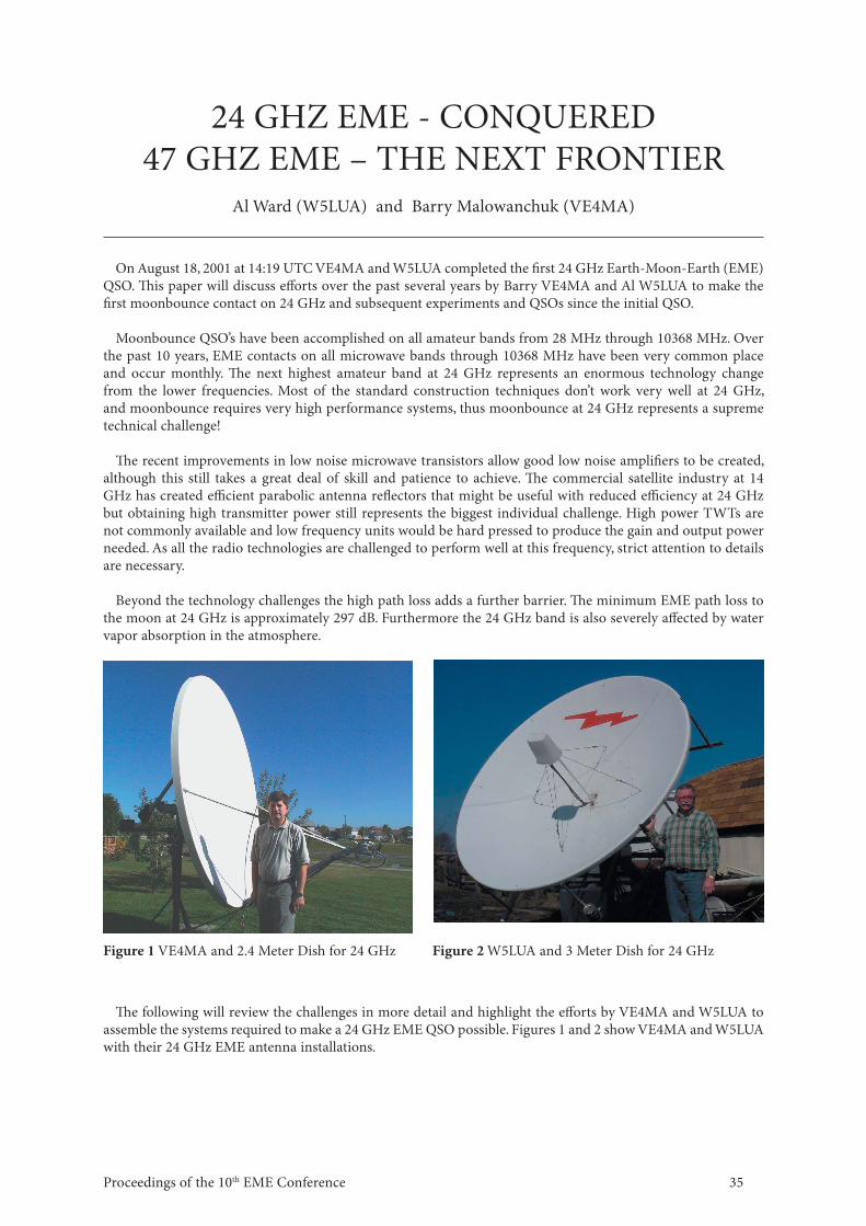
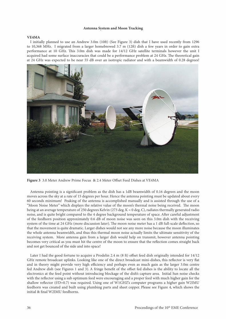
Figure 1 VE4MA and 2.4 Meter Dish for 24 GHz Figure 2 W5LUA and 3 Meter Dish for 24 GHz
Th e following will review the challenges in more detail and highlight the eff orts by VE4MA and W5LUA to assemble the systems required to make a 24 GHz EME QSO possible. Figures 1 and 2 show VE4MA and W5LUA with their 24 GHz EME antenna installations.
Proceedings of the 10th EME Conference 36
Antenna System and Moon Tracking
VE4MAI initially planned to use an Andrew 3.0m (10ft ) (See Figure 3) dish that I have used recently from 1296
to 10,368 MHz. I migrated from a larger homebrewed 3.7 m (12ft ) dish a few years in order to gain extra performance at 10 GHz. Th is 3.0m dish was made for 14/12 GHz satellite terminals however the unit I acquired had some surface inaccuracies that could be a performance problem at 24 GHz. Th e theoretical gain at 24 GHz was expected to be near 55 dB over an isotropic radiator and with a beamwidth of 0.28 degrees!
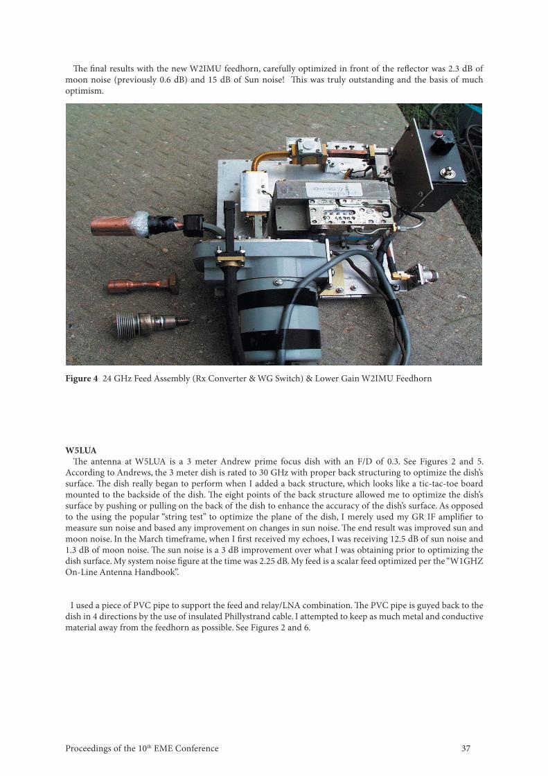
Figure 3 3.0 Meter Andrew Prime Focus & 2.4 Meter Off set Feed Dishes at VE4MA
Antenna pointing is a signifi cant problem as the dish has a 1dB beamwidth of 0.16 degrees and the moon moves across the sky at a rate of 15 degrees per hour. Hence the antenna pointing must be updated about every 60 seconds minimum! Peaking of the antenna is accomplished manually and is assisted through the use of a “Moon Noise Meter” which displays the relative value of the moon’s thermal noise being received. Th e moon being at an average temperature of 250 degrees Kelvin (273 deg. K = 0 deg. C), radiates thermally generated radio noise, and is quite bright compared to the 4 degree background temperature of space. Aft er careful adjustment of the feedhorn position approximately 0.6 dB of moon noise was seen on this 3.0m dish with the receiving system of the time at 24 GHz (more discussion later). Th e moon noise meter has a 1 dB full-scale defl ection, so that the movement is quite dramatic. Larger dishes would not see any more noise because the moon illuminates the whole antenna beamwidth, and thus this thermal moon noise actually limits the ultimate sensitivity of the receiving system. More antenna gain from a larger dish would help on transmit, however antenna pointing becomes very critical as you must hit the centre of the moon to ensure that the refl ection comes straight back and not get bounced of the side and into space!
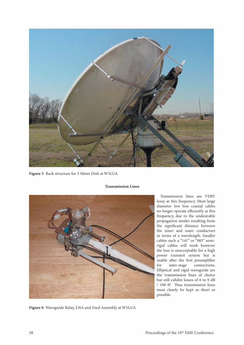
Later I had the good fortune to acquire a Prodelin 2.4 m (8 ft ) off set feed dish originally intended for 14/12 GHz remote broadcast uplinks. Looking like one of the direct broadcast mini-dishes, this refl ector is very fl at and in theory might provide very high effi ciency and perhaps even as much gain as the larger 3.0m centre fed Andrew dish (see Figures 1 and 3). A fringe benefi t of the off set fed dishes is the ability to locate all the electronics at the feed point without introducing blockage of the dish’s capture area. Initial Sun noise checks with the refl ector using a sub optimum feed were encouraging and a proper feed with much higher gain for the shallow refl ector (f/D=0.7) was required. Using one of W1GHZ’s computer programs a higher gain W2IMU feedhorn was created and built using plumbing parts and sheet copper. Please see Figure 4, which shows the initial & fi nal W2IMU feedhorns.
37Proceedings of the 10th EME Conference
Th e fi nal results with the new W2IMU feedhorn, carefully optimized in front of the refl ector was 2.3 dB of moon noise (previously 0.6 dB) and 15 dB of Sun noise! Th is was truly outstanding and the basis of much optimism.
Figure 4 24 GHz Feed Assembly (Rx Converter & WG Switch) & Lower Gain W2IMU Feedhorn
W5LUATh e antenna at W5LUA is a 3 meter Andrew prime focus dish with an F/D of 0.3. See Figures 2 and 5.
According to Andrews, the 3 meter dish is rated to 30 GHz with proper back structuring to optimize the dish’s surface. Th e dish really began to perform when I added a back structure, which looks like a tic-tac-toe board mounted to the backside of the dish. Th e eight points of the back structure allowed me to optimize the dish’s surface by pushing or pulling on the back of the dish to enhance the accuracy of the dish’s surface. As opposed to the using the popular “string test” to optimize the plane of the dish, I merely used my GR IF amplifi er to measure sun noise and based any improvement on changes in sun noise. Th e end result was improved sun and moon noise. In the March timeframe, when I fi rst received my echoes, I was receiving 12.5 dB of sun noise and 1.3 dB of moon noise. Th e sun noise is a 3 dB improvement over what I was obtaining prior to optimizing the dish surface. My system noise fi gure at the time was 2.25 dB. My feed is a scalar feed optimized per the “W1GHZ On-Line Antenna Handbook”.
I used a piece of PVC pipe to support the feed and relay/LNA combination. Th e PVC pipe is guyed back to the dish in 4 directions by the use of insulated Phillystrand cable. I attempted to keep as much metal and conductive material away from the feedhorn as possible. See Figures 2 and 6.
Proceedings of the 10th EME Conference 38
Transmission Lines
Transmission lines are VERY lossy at this frequency. Most large diameter low loss coaxial cables no longer operate effi ciently at this frequency, due to the undesirable propagation modes resulting from the signifi cant distance between the inner and outer conductors in terms of a wavelength. Smaller cables such a “141” or “085” semi-rigid cables will work however the loss is unacceptable for a high power transmit system but is usable aft er the fi rst preamplifi er for inter-stage connections. Elliptical and rigid waveguide are the transmission lines of choice but still exhibit losses of 6 to 9 dB / 100 ft ! Th us transmission lines must clearly be kept as short as possible.
Figure 5 Back structure for 3 Meter Dish at W5LUA
Figure 6 Waveguide Relay, LNA and Feed Assembly at W5LUA
39Proceedings of the 10th EME Conference
WR-42 rectangular waveguide is the best choice for rigid lines and it exhibits a loss of about 11dB/100 ft . WR-28 and WR-62 could be used for short runs (a few centimeters or 1 inch).Th e Elliptical waveguides off er lower losses and being fl exible also off er ease of use over rigid waveguide. Th ere are two choices for elliptical waveguides Andrew EW220 and EW180 and equivalents from other manufacturers. EW180 is rated from 14-20 GHz but with care (no sharp bends) will work and can produce losses of under 6 dB/100 ft . EW220 is designed for 17-24 GHz and is specifi ed with a loss of about 8.5 dB/100 ft .
EW180 is used at VE4MA for the transmit feedlines from the feedpoint of the dish to inside the ham shack in order to avoid exposing transmitter equipment to extreme weather. Th e very high voltage TWT power supplies do not like high humidity while the tubes themselves do not take well to cold temperatures.
With very large prime focus dishes, the transmitter feed line loss from the dish feedpoint back to the operating position could be prohibitive, and thus great eff ort is oft en put into mounting the transmit power amplifi er as close as possible to the dish. Ideally it should be mounted along with the receive preamplifi ers and relays right at the feedpoint of the dish but that is usually is impractical for prime focus dishes. Th is is where the off set or rear fed dishes excel by having the feedhorn outside the capture area of the dish. At W5LUA, I use a combination of rigid and fl exible waveguide to connect the output of my TWT to the waveguide relay. I use a 3ft piece of rigid WR-42 waveguide from the waveguide relay at the feed to a point just behind the dish where I continue with a 12 inch length of WR-42 fl exible waveguide to the TWT. Th e TWT and transverter are mounted on a shelf, which is attached to the back of the dish. Th ere is an advantage of a low 0.3 f/d dish, i.e. short length from feed to back of dish! Regardless of what type of antenna is used, every eff ort must be made to minimize transmit feedline loss by keeping it as short as possible and even putting the transmitter out by the dish if practical.
Receiving and Low level Transmitting Equipment
VE4MATh e system is homebuilt and the use of surplus components for the up/down converters signifi cantly
minimized the work required. My station starts with an old Icom IC-490 70cm Multimode transceiver, which works into a transverter to convert the signals to and from 24 GHz. I also use a separate 70 cm receive converter down to 28 MHz to drive an HF receiver and the moon noise meter. Th e system is linear and highly stable so that CW, SSB and even FM could be used if signal levels permitted.
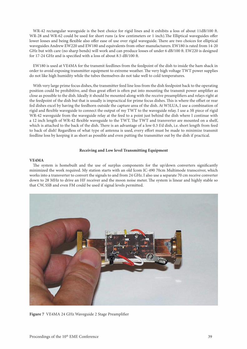
Figure 7 VE4MA 24 GHz Waveguide 2 Stage Preamplifi er
Proceedings of the 10th EME Conference 40
Th e receiving preamplifi ers can be home built but achieving the very best noise fi gures can be extremely diffi cult. I have created a good noise fi gure measurement system and believe I am reasonably skilled at tuning these preamplifi ers with small copper tabs. I have built about 6 waveguide input/ output preamplifi ers using a variety of devices and achieved mixed results. Th e best results of 2.3 dB NF were with an Agilent ATF36077 PHEMT FET (see fi gure 7). Th is preamplifi er was used with the initial tests with my 3m dish.
Th ere are designs published and PC boards, parts and even assembled units can be obtained if desired from a few European suppliers. As discussed earlier coaxial cable is extremely lossy so that the input to the moonbounce preamplifi ers must use WR-42 rectangular waveguide. Th e WR-42 waveguide input also provides a convenient method of tuning for lowest noise fi gure with screws at the appropriate positions
In the interest of improving things further and moving on to the power amplifi er work, I purchased a 3 stage preamplifi er from DB6NT. Th is unit delivers an extremely impressive 1.55 dB NF @28 dB gain and represents the state of the art and was well worth the cost!
W5LUA
My transverter is also homebrew and mounted out behind the dish on a shelf along with the TWT. Th e transverter uses a DMC LO and a DMC power amplifi er providing 50 milliwatts on transmit. I use cascaded homebrew LNAs to set the system noise fi gure. Th e LNA that I used to hear my fi rst echoes on 24 GHz is a homebrew 2 stage W5LUA design using a pair of Agilent Technologies PHEMT devices which provided a 2.25 dB system noise fi gure. I have since acquired some lower noise fi gure devices which has produced a 1.75 dB system noise fi gure. Th e transverter is dual conversion with a fi rst IF of 2304 MHz and a second IF of 144 MHz. Th e 144 MHz is piped into the shack. My IF radio is an ICOM IC-271. I sample some of the 2 meter IF signal and down-convert even further to 28 MHz. Th e 28 MHz feeds both a GR-1216 IF amplifi er for measuring sun and moon noise and also a Drake R7 receiver. Although I have used my IC-271 for nearly every EME and tropo QSO I have made through 10 GHz, I must admit the R7 receiver produced an easier to copy signal off the moon on 24 GHz. Th e Drake R7 receiver was originally used by W4HHK for his IF on 2304 MHz EME so it is carrying on the EME tradition.
Transmitter Power Amplifi ers
Transmitter power is the most diffi cult thing to achieve. Modern solid-state amplifi ers are available on the surplus market up to about ½ Watt, but above this we must rely on traveling wave tube amplifi ers (TWTA). Most 24 GHz rated TWTAs that become surplus are instrumentation units that at are only rated at 1 Watt output, while lower frequency TWTAs (e.g. 12-18 GHz) are usually rated to about 25 Watts. All TWT amplifi ers are usually capable of considerably more power if the focusing voltages are optimized for the specifi c frequency of interest.
VE4MAMy initial power amplifi er work focused on trying to get Varian and Hughes 18 GHz instrumentation
amplifi ers to move up to 24 GHz. Unfortunately these surplus amplifi ers units are oft en surplus because the power supply and or the TWT itself are defective. I spent many weeks time in reverse engineering switching power supplies, only to fi nd that the tubes are also bad. My best results with a Hughes 1177 10 Watt amplifi er was a best of 5 Watts out with only about 17 dB of gain. Notably the low frequency minimum gain specifi cation is 30 dB. With such low gain a driver of about 100 mW is required. I have also tried to use the Hughes 1277 (20 Watt) with very poor results Th e best results were obtained with a Hughes 1177 amplifi er driving a Logimetrics 10 Watt 8-18 GHz amplifi er (ITT tube) to achieve 11 Watts on 24 GHz.
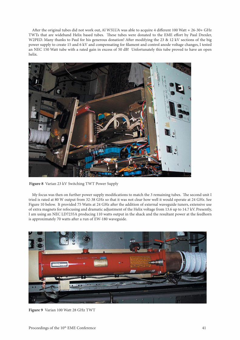
I was fortunate to acquire some 4 Varian 100Watt 28 GHz TWTs and power supplies. Unfortunately these TWTs proved to be narrow band “cavity coupled” tubes and produced no output at 24 GHz. Th e power supplies are very impressive providing a regulated 23 kV, 12 kV at 150 mA, etc. from a 220V single-phase line. Physically these are hidden behind a 14 inch high 19 inch rack panel and are about 30 inches deep and weigh over 100 pounds. Fortunately there was a complete set of schematics for these power supplies, which has proven to be very important for future work. Please see fi gures 8 & 9.
41Proceedings of the 10th EME Conference
Aft er the original tubes did not work out, Al W5LUA was able to acquire 4 diff erent 100 Watt + 26-30+ GHz TWTs that are wideband Helix based tubes. Th ese tubes were donated to the EME eff ort by Paul Drexler, W2PED. Many thanks to Paul for his generous donation! Aft er modifying the 23 & 12 kV sections of the big power supply to create 15 and 6 kV and compensating for fi lament and control anode voltage changes, I tested an NEC 150 Watt tube with a rated gain in excess of 50 dB! Unfortunately this tube proved to have an open helix.
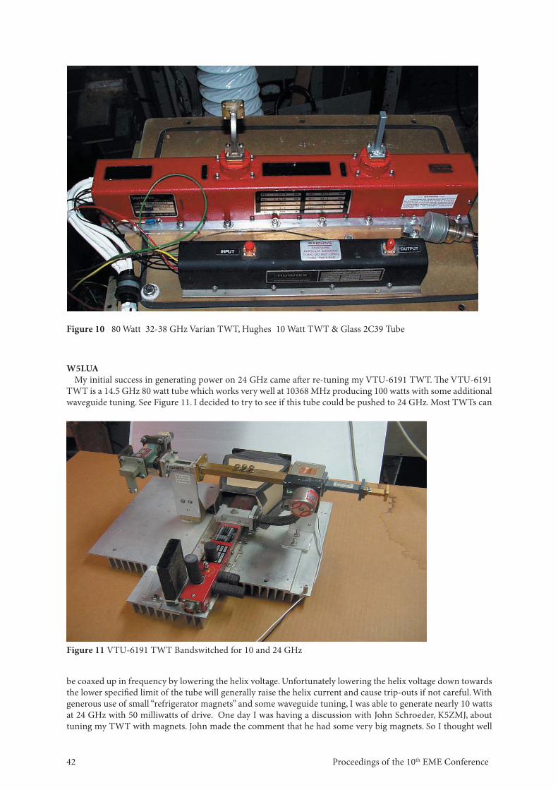
My focus was then on further power supply modifi cations to match the 3 remaining tubes. Th e second unit I tried is rated at 80 W output from 32-38 GHz so that it was not clear how well it would operate at 24 GHz. See Figure 10 below. It provided 75 Watts at 24 GHz aft er the addition of external waveguide tuners, extensive use of extra magnets for refocusing and dramatic adjustment of the Helix voltage from 13.6 up to 14.7 kV. Presently, I am using an NEC LD7235A producing 110 watts output in the shack and the resultant power at the feedhorn is approximately 70 watts aft er a run of EW-180 waveguide.
Figure 9 Varian 100 Watt 28 GHz TWT
Figure 8 Varian 23 kV Switching TWT Power Supply
Proceedings of the 10th EME Conference 42
Figure 10 80 Watt 32-38 GHz Varian TWT, Hughes 10 Watt TWT & Glass 2C39 Tube
W5LUAMy initial success in generating power on 24 GHz came aft er re-tuning my VTU-6191 TWT. Th e VTU-6191
TWT is a 14.5 GHz 80 watt tube which works very well at 10368 MHz producing 100 watts with some additional waveguide tuning. See Figure 11. I decided to try to see if this tube could be pushed to 24 GHz. Most TWTs can
be coaxed up in frequency by lowering the helix voltage. Unfortunately lowering the helix voltage down towards the lower specifi ed limit of the tube will generally raise the helix current and cause trip-outs if not careful. With generous use of small “refrigerator magnets” and some waveguide tuning, I was able to generate nearly 10 watts at 24 GHz with 50 milliwatts of drive. One day I was having a discussion with John Schroeder, K5ZMJ, about tuning my TWT with magnets. John made the comment that he had some very big magnets. So I thought well
Figure 11 VTU-6191 TWT Bandswitched for 10 and 24 GHz
43Proceedings of the 10th EME Conference
why not try one and see what happens. Th e fi rst thing that happened was that I noticed it was a lot easier to trip out the helix current when placing the magnet in the “wrong” position! Aft er careful positioning near the input waveguide connector, I was able to get nearly 20 watts output, a gain of 3 dB over my previous best. At this power level, I was able to hear my fi rst echoes off the moon in March 2001. Also note the bandswitch between 10 and 24 GHz as shown in Figure 11.When I operate 10 GHz, I MUST remove the large magnet!
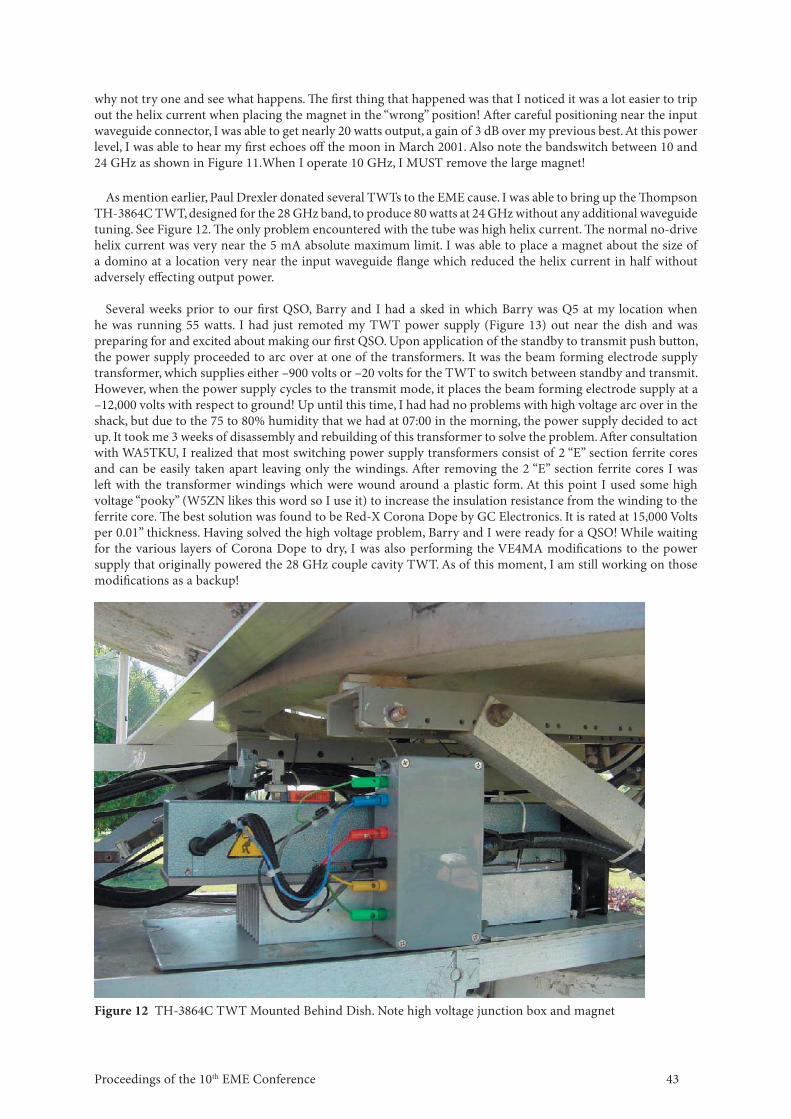
As mention earlier, Paul Drexler donated several TWTs to the EME cause. I was able to bring up the Th ompson TH-3864C TWT, designed for the 28 GHz band, to produce 80 watts at 24 GHz without any additional waveguide tuning. See Figure 12. Th e only problem encountered with the tube was high helix current. Th e normal no-drive helix current was very near the 5 mA absolute maximum limit. I was able to place a magnet about the size of a domino at a location very near the input waveguide fl ange which reduced the helix current in half without adversely eff ecting output power.
Several weeks prior to our fi rst QSO, Barry and I had a sked in which Barry was Q5 at my location when
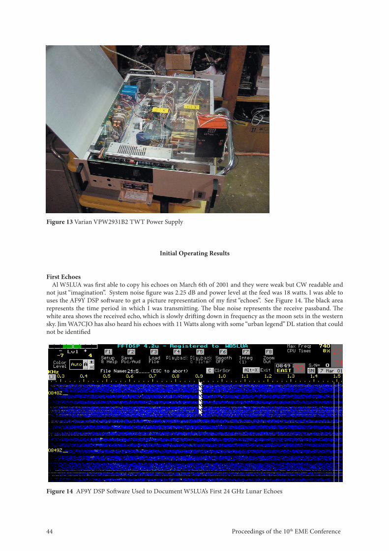
he was running 55 watts. I had just remoted my TWT power supply (Figure 13) out near the dish and was preparing for and excited about making our fi rst QSO. Upon application of the standby to transmit push button, the power supply proceeded to arc over at one of the transformers. It was the beam forming electrode supply transformer, which supplies either –900 volts or –20 volts for the TWT to switch between standby and transmit. However, when the power supply cycles to the transmit mode, it places the beam forming electrode supply at a –12,000 volts with respect to ground! Up until this time, I had had no problems with high voltage arc over in the shack, but due to the 75 to 80% humidity that we had at 07:00 in the morning, the power supply decided to act up. It took me 3 weeks of disassembly and rebuilding of this transformer to solve the problem. Aft er consultation with WA5TKU, I realized that most switching power supply transformers consist of 2 “E” section ferrite cores and can be easily taken apart leaving only the windings. Aft er removing the 2 “E” section ferrite cores I was left with the transformer windings which were wound around a plastic form. At this point I used some high voltage “pooky” (W5ZN likes this word so I use it) to increase the insulation resistance from the winding to the ferrite core. Th e best solution was found to be Red-X Corona Dope by GC Electronics. It is rated at 15,000 Volts per 0.01” thickness. Having solved the high voltage problem, Barry and I were ready for a QSO! While waiting for the various layers of Corona Dope to dry, I was also performing the VE4MA modifi cations to the power supply that originally powered the 28 GHz couple cavity TWT. As of this moment, I am still working on those modifi cations as a backup!
Figure 12 TH-3864C TWT Mounted Behind Dish. Note high voltage junction box and magnet
Proceedings of the 10th EME Conference 44
Initial Operating Results
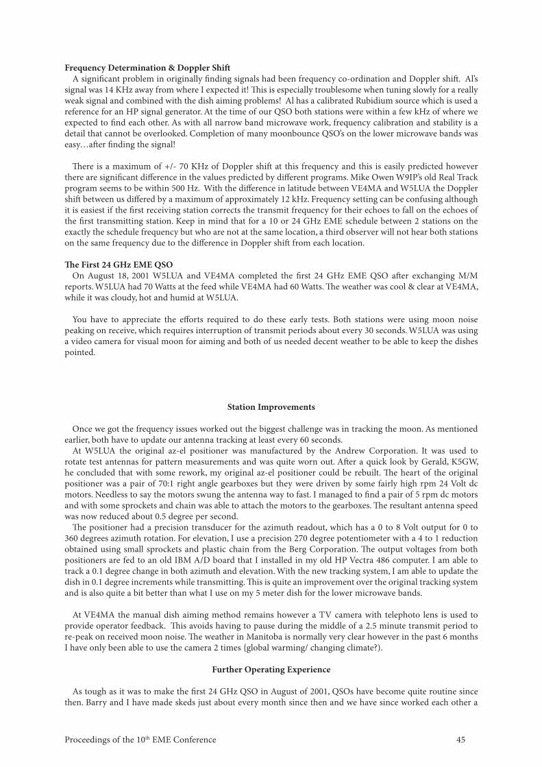
First EchoesAl W5LUA was fi rst able to copy his echoes on March 6th of 2001 and they were weak but CW readable and
not just “imagination”. System noise fi gure was 2.25 dB and power level at the feed was 18 watts. I was able to uses the AF9Y DSP soft ware to get a picture representation of my fi rst “echoes”. See Figure 14. Th e black area represents the time period in which I was transmitting. Th e blue noise represents the receive passband. Th e white area shows the received echo, which is slowly drift ing down in frequency as the moon sets in the western sky. Jim WA7CJO has also heard his echoes with 11 Watts along with some “urban legend” DL station that could not be identifi ed
Figure 14 AF9Y DSP Soft ware Used to Document W5LUA’s First 24 GHz Lunar Echoes
Figure 13 Varian VPW2931B2 TWT Power Supply
45Proceedings of the 10th EME Conference
Frequency Determination & Doppler Shift A signifi cant problem in originally fi nding signals had been frequency co-ordination and Doppler shift . Al’s
signal was 14 KHz away from where I expected it! Th is is especially troublesome when tuning slowly for a really weak signal and combined with the dish aiming problems! Al has a calibrated Rubidium source which is used a reference for an HP signal generator. At the time of our QSO both stations were within a few kHz of where we expected to fi nd each other. As with all narrow band microwave work, frequency calibration and stability is a detail that cannot be overlooked. Completion of many moonbounce QSO’s on the lower microwave bands was easy…aft er fi nding the signal!
Th ere is a maximum of +/- 70 KHz of Doppler shift at this frequency and this is easily predicted however there are signifi cant diff erence in the values predicted by diff erent programs. Mike Owen W9IP’s old Real Track program seems to be within 500 Hz. With the diff erence in latitude between VE4MA and W5LUA the Doppler shift between us diff ered by a maximum of approximately 12 kHz. Frequency setting can be confusing although it is easiest if the fi rst receiving station corrects the transmit frequency for their echoes to fall on the echoes of the fi rst transmitting station. Keep in mind that for a 10 or 24 GHz EME schedule between 2 stations on the exactly the schedule frequency but who are not at the same location, a third observer will not hear both stations on the same frequency due to the diff erence in Doppler shift from each location.
Th e First 24 GHz EME QSOOn August 18, 2001 W5LUA and VE4MA completed the fi rst 24 GHz EME QSO aft er exchanging M/M
reports. W5LUA had 70 Watts at the feed while VE4MA had 60 Watts. Th e weather was cool & clear at VE4MA, while it was cloudy, hot and humid at W5LUA.
You have to appreciate the eff orts required to do these early tests. Both stations were using moon noise
peaking on receive, which requires interruption of transmit periods about every 30 seconds. W5LUA was using a video camera for visual moon for aiming and both of us needed decent weather to be able to keep the dishes pointed.
Station Improvements
Once we got the frequency issues worked out the biggest challenge was in tracking the moon. As mentioned earlier, both have to update our antenna tracking at least every 60 seconds.
At W5LUA the original az-el positioner was manufactured by the Andrew Corporation. It was used to rotate test antennas for pattern measurements and was quite worn out. Aft er a quick look by Gerald, K5GW, he concluded that with some rework, my original az-el positioner could be rebuilt. Th e heart of the original positioner was a pair of 70:1 right angle gearboxes but they were driven by some fairly high rpm 24 Volt dc motors. Needless to say the motors swung the antenna way to fast. I managed to fi nd a pair of 5 rpm dc motors and with some sprockets and chain was able to attach the motors to the gearboxes. Th e resultant antenna speed was now reduced about 0.5 degree per second.
Th e positioner had a precision transducer for the azimuth readout, which has a 0 to 8 Volt output for 0 to 360 degrees azimuth rotation. For elevation, I use a precision 270 degree potentiometer with a 4 to 1 reduction obtained using small sprockets and plastic chain from the Berg Corporation. Th e output voltages from both positioners are fed to an old IBM A/D board that I installed in my old HP Vectra 486 computer. I am able to track a 0.1 degree change in both azimuth and elevation. With the new tracking system, I am able to update the dish in 0.1 degree increments while transmitting. Th is is quite an improvement over the original tracking system and is also quite a bit better than what I use on my 5 meter dish for the lower microwave bands.
At VE4MA the manual dish aiming method remains however a TV camera with telephoto lens is used to provide operator feedback. Th is avoids having to pause during the middle of a 2.5 minute transmit period to re-peak on received moon noise. Th e weather in Manitoba is normally very clear however in the past 6 months I have only been able to use the camera 2 times {global warming/ changing climate?).
Further Operating Experience
As tough as it was to make the fi rst 24 GHz QSO in August of 2001, QSOs have become quite routine since then. Barry and I have made skeds just about every month since then and we have since worked each other a
Proceedings of the 10th EME Conference 46
total of 10 times with “O” copy signals most of the time. We used this time to test improvements to our systems, encourage other stations to listen and learn more about 24 GHz EME conditions.
Reception ReportsSince our initial QSO we have been heard by G3WDG, RW3BP, VE7CLD and AA6IW. RW3BP has been
hearing both Barry and I almost every time we have been on. All stations have been using dishes that range from a 2.4 m off set fed to a 4.5m prime focus unit, and are using preamplifi ers of approximately 2 dB noise fi gure. Just as the EME experience at 10 GHz has shown, moon noise at 24 GHz limits the ultimate receiver sensitivity, so that a large dish and a “really good” preamplifi er do not produce signifi cantly better received signals. “Small” receive stations should be able to hear signals, however in order to be heard above the moon noise, the transmit ERP cannot be reduced.
In addition to the stations providing reception reports mentioned earlier, several other stations in Europe such as LX1DB, CT1DMK, OH2AUE, OK1UWA and more recently PA0EHG are capable of receiving but lack the transmitters with above 1 Watt output. Others interested in the AO-40 satellite should be able to receive 24 GHz EME signals.
Notably VE7CLD, AA6IW and WA7CJO have TWTAs capable of producing power in the 100 watt class. RW3BP has received a high power TWT and currently has it operational with a homebrew power supply! G3WDG has a tube but is awaiting the results of some TWT power supply testing that should be completed in early summer. With so many stations nearing operation many new 24 GHz QSOs are expected later this year.
Power Level TestingBarry and I ran power level tests in January that help give some insight as to how high above threshold our
signals are. For reference both Barry and I run about 70 watts at the feed. My TWT is mounted just behind the dish and Barry’s TWT is located in the house and actually runs about 110 watts and with waveguide losses delivers about 70 watts as measured at the feed. We ran an hour sked and proceeded to reduce power very 15 minutes. Th e fi rst 15 minutes was easy “O” copy at the 70 Watt level. Th e next 15 minutes was using 35 watts output. Signals were still “O” copy. Th e third 15 minute period was run at the 17 watt level. Signals were “M” copy and about at the same level as my echoes were in March 2001. “M” copy is about the minimum level required to hear a complete set of calls. We did not lower the power level any further. I would guess that at 10 watts at the feed, signals would be identifi able especially if one were to place their echoes on top of the stronger signal. Hunting for a 10 watt station calling CQ at 24 GHz, would be a challenge.
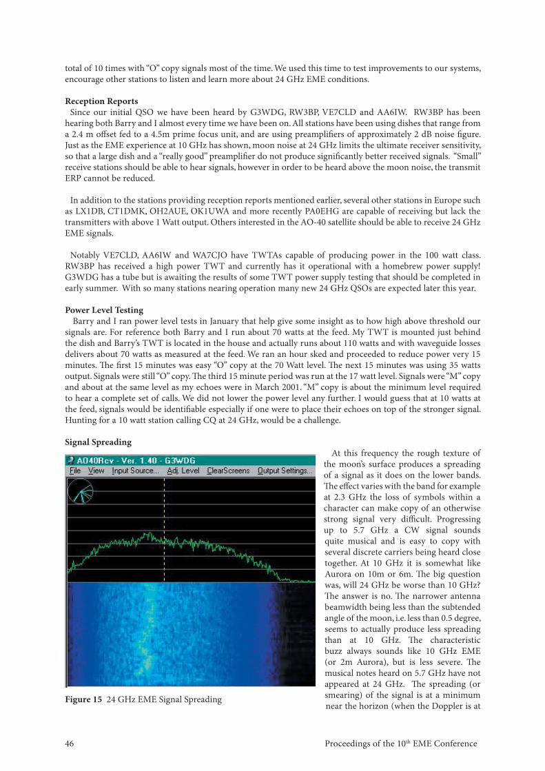
Signal SpreadingAt this frequency the rough texture of
the moon’s surface produces a spreading of a signal as it does on the lower bands. Th e eff ect varies with the band for example at 2.3 GHz the loss of symbols within a character can make copy of an otherwise strong signal very diffi cult. Progressing up to 5.7 GHz a CW signal sounds quite musical and is easy to copy with several discrete carriers being heard close together. At 10 GHz it is somewhat like Aurora on 10m or 6m. Th e big question was, will 24 GHz be worse than 10 GHz? Th e answer is no. Th e narrower antenna beamwidth being less than the subtended angle of the moon, i.e. less than 0.5 degree, seems to actually produce less spreading than at 10 GHz. Th e characteristic buzz always sounds like 10 GHz EME (or 2m Aurora), but is less severe. Th e musical notes heard on 5.7 GHz have not appeared at 24 GHz. Th e spreading (or smearing) of the signal is at a minimum near the horizon (when the Doppler is at
Figure 15 24 GHz EME Signal Spreading
47Proceedings of the 10th EME Conference
a maximum) and increases to a maximum as the moon passes directly south (Doppler minimum).To illustrate the spreading of signals please see fi gure 15, which is a spectrum display received from Charlie
G3WDG. Clearly the CW signal shown from VE4MA is widely spread. Th e horizontal scale is 3.5 kHz. Th e moon at the time was about 30 degrees above the horizon at both ends, so that the spreading is probably about what can be normally expected. As the moon gets closer to directly south the spreading is much more severe and readability is severely aff ected. Conversely at moon rise/ set the spreading is at a minimum. Sergei RW3BP has observed signals with only a 7.5 degree elevation on a setting moon. At the time signals from VE4MA (moon getting close to south ~ -25 LHA) while for AA6IW the moon was very low in the Eastern sky. Sergei noted almost no spreading (a very sharp signal) from AA6IW, while VE4MA was very distorted. At this time VE4MA observed a high amount of spreading on all signals.
Eff ect of Seasons & Elevation Angle on System Performance Th ere is a large water absorption peak (resonance) in the atmosphere just below 24 GHz. Th e loss going
through the atmosphere will thus vary with the amount of water vapor, which is related to the ambient temperature and the weather. In the colder atmosphere at VE4MA it should be expected that the water vapor level and hence absorption will be signifi cantly less than at W5LUA (Dallas area). Th e absorption in the atmosphere has 2 eff ects, pure path attenuation and an increase in sky temperature. A receiver looking at a 4 degrees Kelvin cold sky will see a sky temperature increase from the “temperature” of the path attenuation as well as perhaps some back scattering from the warm earth.
Th e high values of moon noise achieved in winter dropped dramatically to as low as 1.2 dB (vs. 2.3 dB) at VE4MA and down to 0.8 dB (vs. 1.3dB) at W5LUA. Th e receive performance had dropped in summer due to the combined eff ects of increased atmospheric absorption and the rise in ambient operating temperature. Please consider that for the winter tests the ambient temperature at VE4MA was ~ –30 C vs. +25-35 C in summer! For Al W5LUA the moon noise received peaked at about 1.6 dB for only a relatively short period in February and March, before the higher temperatures and water vapor returned.
Since clouds are water vapor it would be expected that they would have a signifi cant eff ect. Th e fi rst reception of W5LUA by VE4MA and also the fi rst QSO between W5LUA and VE4MA occurred through high altitude clouds at VE4MA that were thick enough to obscure visual tracking of the moon but had no apparent eff ect on reception. Some time earlier on the occasion of the fi rst sun/moon noise checks at VE4MA, the tests were conducted during a hot summer day that had low and thick cloud cells producing local rain showers. As the clouds passed the moon noise was observed to be very erratic with signifi cant drops. Th is weather is unusual at VE4MA but served to show the eff ects.
Th e local elevation angle of the moon was found to be very important. All stations have observed that the moon noise is reduced below about 30 degrees elevation. Th is is surely due to the eff ect of the atmosphere discussed earlier and perhaps some ground noise pickup from sidelobes of the dish. Even at lower frequencies the antenna temperatures increase with elevation angles less than 30 degrees. Considering the higher receive noise fi gures (system temperatures) of 24 GHz systems the increase in antenna temperature should not be a signifi cant contributor.
More QSOs
As mentioned above several new stations were preparing for activity on 24 GHz EME. All of the work culminated in a major rush of activity in April 2002 as follows:
April 18 RW3BP QSO’d W5LUA “M/M” Initial QSO for RW3BPApril 20 RW3BP QSO’d VE4MA “O/M”April 20 VE4MA QSO’d VE7CLD “M/M” Initial QSO for VE7CLDApril 20 RW3BP QSO’d AA6IW “M/O” Initial QSO for AA6IWApril 21 VE4MA QSO’d AA6IW “M/M”
Proceedings of the 10th EME Conference 48
Th e QSO between RW3BP and AA6IW is note worthy since the QSO ended with only 7.5 degrees of elevation at RW3BP. Atmospheric attenuation should have been higher and Sergei’s receive performance degraded, but it seems that the low level of signal spreading compensated for it. Th is also sets a new distance record of 8392.9 km from KO85ws to CN87vi. Unfortunately W5LUA was away for April 20/21, so the May weekend should provide some great activity.
New Station Details
RW3BP
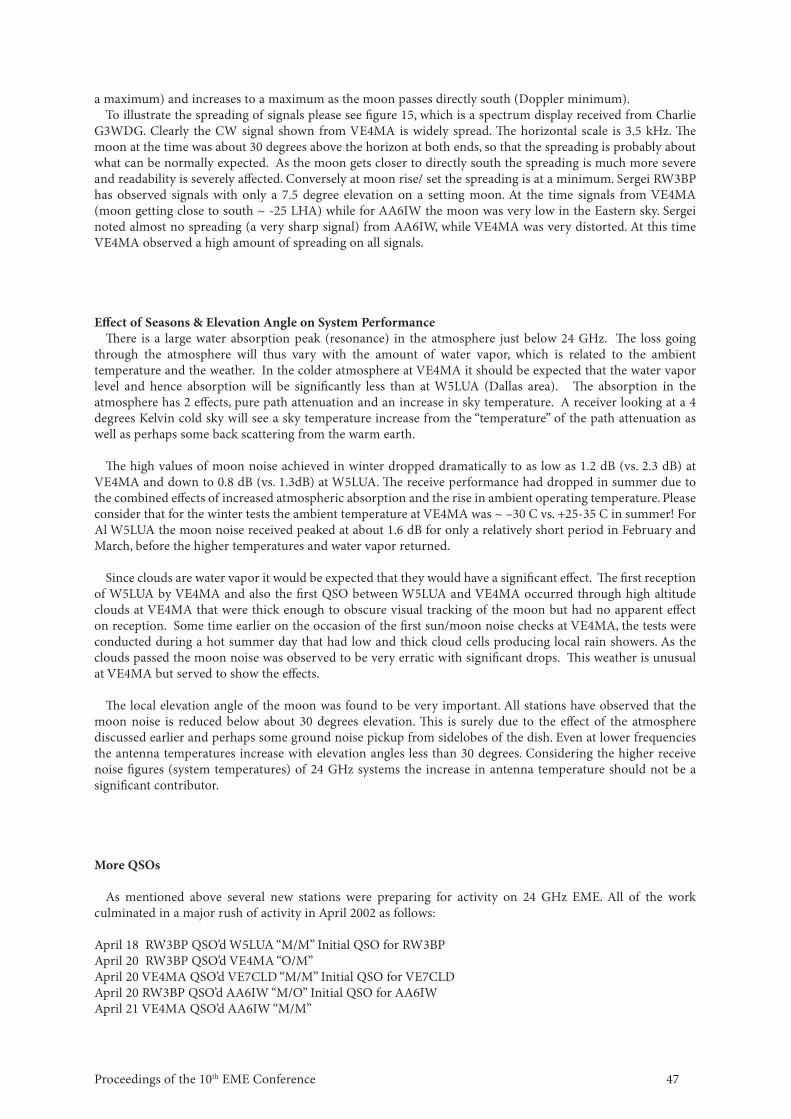
Figure 16 RW3BP 3 Meter Dish for 24 GHz Figure 17 Water Cooled TWT at FeedPoint
Sergei RW3BP is the third station to have a successful 24 GHz QSO. He is using a 2.4 m off set fed dish, with an Alelco 100 Watt water cooled TWT mounted right at the feedpoint as shown in fi gure 17 . Th e high voltage power supply was built by Sergei using parts from X Ray machine power supplies and is remotely connected to the feedpoint mounted TWT through extension cables. A 1.6 dB noise fi gure DB6NT preamplifi er provides consistently more than 2 dB of moon noise and 15 dB of sun noise. Sergei has copied nearly all VE4MA & W5LUA 24 GHz QSOs. Sergei uses an ingenious mechanical scheme to move the transmit and receive feedhorns into the proper position , thus eliminating the need for a waveguide switch. During transmit periods the receive feedhorn opening is covered by lossy rubber as an extra safety measure.
Figure 18 Mechanical TX/RX Switching at Feed
49Proceedings of the 10th EME Conference
AA6IW
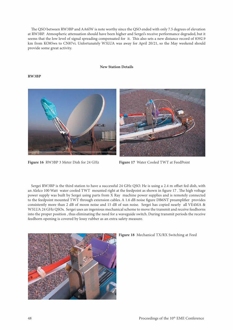
Lars became the fourth station to complete a 24 GHz EME QSO and is using a Prodelin 2.4 m off set fed dish similar to the one used by VE4MA. Lars has a 1.6 dB noise fi gure DB6NT preamplifi er and a 100 Watt class Varian TWT amplifi er. His dish is computer controlled and has readouts accurate to ~0.005 degrees but he has noticed tracking problems with many of the available tracking programs. Lars and Sergei have both noticed that the Doppler predictions from tracking programs have signifi cant errors, but will require further study.
VE7CLD
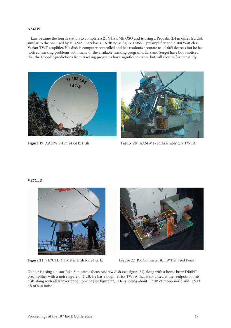
Gunter is using a beautiful 4.5 m prime focus Andrew dish (see fi gure 21) along with a home brew DB6NT preamplifi er with a noise fi gure of 2 dB. He has a Logimetrics TWTA that is mounted at the feedpoint of his dish along with all tranverter equipment (see fi gure 22). He is seeing about 1.2 dB of moon noise and 12-13 dB of sun noise.
Figure 19 AA6IW 2.4 m 24 GHz Dish Figure 20 AA6IW Feed Assembly c/w TWTA
Figure 21 VE7CLD 4.5 Meter Dish for 24 GHz Figure 22 RX Converter & TWT at Feed Point
Proceedings of the 10th EME Conference 50
What Could Possibly Be Next? 47 GHz EME……Naturally!
As much of a challenge that 24 GHz EME was, 47 GHz is going to be exponentially tougher. At this frequency everything is more diffi cult to do and the availability of good test equipment and parts is limited. Th e creation of components for a 47 GHz EME system is virtually beyond amateur construction capabilities so the use of military/ commercial pieces is essential.
AntennasFrom the EME work at 24 GHz it appears that a dish approximately 1.2 m diameter will be needed to provide
similar gain (beamwidth ~0.3 degrees) . Th is is probably the minimum size required and fi nding anything larger that will provide good effi ciency will be diffi cult. Th ere are a lot of 1.2 m off set dishes around from commercial satellite service, and Prodelin even sells a 30 GHz rated model that should work very well. Th e off set dishes of course tend to be higher effi ciency and facilitate mounting the electronics right at the feed without blockage.
Th e 2.4 m Prodelin dish at VE4MA was tested at 47 GHz and provided a little over 4 dB of sun noise however the noise fi gure of the receiver was poor at 9 dB. Sergei RW3BP has tested his 2.4 m dish (illuminating only 1.5m )and found 4.9 dB of sun and even 0.6 dB of moon noise using a 8 dB DSB noise fi gure DB6NT converter.
W0EOM and AD6FP are also working on a 47 GHz system and getting good sun noise with a relatively small 1 m precision antenna. Yet to be tested are several 1.2 m prime focus ,”plastic” and metal off set dishes at VE4MA as well as the 3m dish at W5LUA.
ReceiversAt 24 GHz we have been able to achieve “state of the art” 1.6 dB noise fi gures with amateur construction
methods. At 47 GHz the ability to build preamplifi ers disappears. Th ere has been a lot of work trying to get packaged devices to work with no apparent success. Th is is the region of the microwave integrated circuit chips. Th ere are many chips available from Raytheon, Agilent, UMS, etc that are primarily designed for commercial microwave service at 40 GHz and more recently to support the next generation of fi bre optic systems at 40 Gbps. Th ese chips off er reasonably gain still at 47 GHz and certainly better noise fi gures than mixers (4-5 dB but the chip and wire technique for using these devices is out of the reach of most amateurs. DB6NT recently wrote an article on the use of microwave chip amplifi ers on 47 GHz and good results were obtained (see the DB6NT Web page), however this is unlikely to become a standard DB6NT off ering.
A big obstacle appears to be the relatively poor noise fi gure performance of harmonic mixers. With a 15 to 20 dB mixer NF the preamplifi er gain requirements to overcome the high noise fi gure, represent a real barrier. Th us recent eff orts at VE4MA and W5LUA have focused on reducing the mixer noise fi gure by using fundamental mixing. At W5LUA, the best surplus mixer found to date is the Phillips ML202938-002 up-converter. Th e mixer was designed for the 39 GHz market and incorporates an internal X3 LO multiplier for fundamental injection into a singly balanced mixer. Although Phillips manufactured both up and down converter mixers, both mixers are passive and therefore bilateral and can be used for both transmit and receive applications. I use a 13 GHz LO which produces a fi rst IF in the 8 GHz frequency range. ( 47 – (3 X 13) = 8 GHz). Since the RF match on the mixer was optimized at 39 GHz, I used a short piece of WR-28 wave-guide and several 0-80 screws to optimize the match at 47 GHz. I was able to reduce the conversion loss from 15 to 20 dB down to something near 10 to 12 dB.
Th e next problem is obtaining suffi cient image rejection. A high IF is thus desirable however this also results in higher conversion losses. Th is image problem is likely to be a further aggravated with use of “low frequency” 40 GHz amplifi ers being stretched to operate at 47 GHz. Th e use of harmonic mixers creates a further problem with images of the 3rd / 4th harmonic products falling within the 33-50 GHz waveguide operating frequency range. Image fi ltering at low loss is required and few easily reproducible fi lter designs have existed until recently. Surplus 39 Ghz fi lters are oft en very narrow band and not easily tuned up in frequency. At W5LUA, I was fortunate enough to be given a 51 GHz diplexer by W0EOM. Th e diplexer consisted of 2 fi lters that were tuned somewhere above 50 GHz. Cutting the diplexer in half with a hack saw yielded 2 fi lters. My borrowed Agilent 50 GHz network analyzer could barely see activity until I was able to start walking the fi lters down in frequency. With a lot of work , I was able to tune both fi lters to 47 GHz. I measured losses at 1.5 dB for one and 2 dB for the other. Th e passband response was good enough that 1296 MHz IFs would be do-able. My system uses a 7920
51Proceedings of the 10th EME Conference
MHz fi rst IF but this was chosen based on where my mixer performance was optimum.
Recent advertisements in the “trade” magazines are now showing commercial preamplifi ers at nearly 1 dB noise fi gure. Further some surplus preamplifi ers are in the hands of amateurs so there may be hope for prospective EME use. Certainly a level of preamplifi er noise fi gure performance less than 5 dB will be required for 47 GHz EME systems as the dish gains and transmitter output performance are unlikely to compare with 24 GHz values.
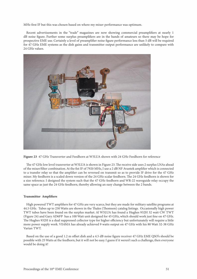
Figure 23 47 GHz Transverter and Feedhorn at W5LUA shown with 24 GHz Feedhorn for reference
Th e 47 GHz low level transverter at W5LUA is shown in Figure 23. Th e receive side uses 2 surplus LNAs ahead of the mixer/fi lter combination. At the fi st IF of 7920 MHz, I use a 2 dB NF Avantek amplifi er which is connected to a transfer relay so that the amplifi er can be reversed on transmit so as to provide IF drive for the 47 GHz mixer. My feedhorn is a scaled down version of the 24 GHz scalar feedhorn. Th e 24 GHz feedhorn is shown for a size reference. I designed the system such that the 47 GHz feedhorn and WR-22 waveguide relay occupy the same space as just the 24 GHz feedhorn, thereby allowing an easy change between the 2 bands.
Transmitter Amplifi ers
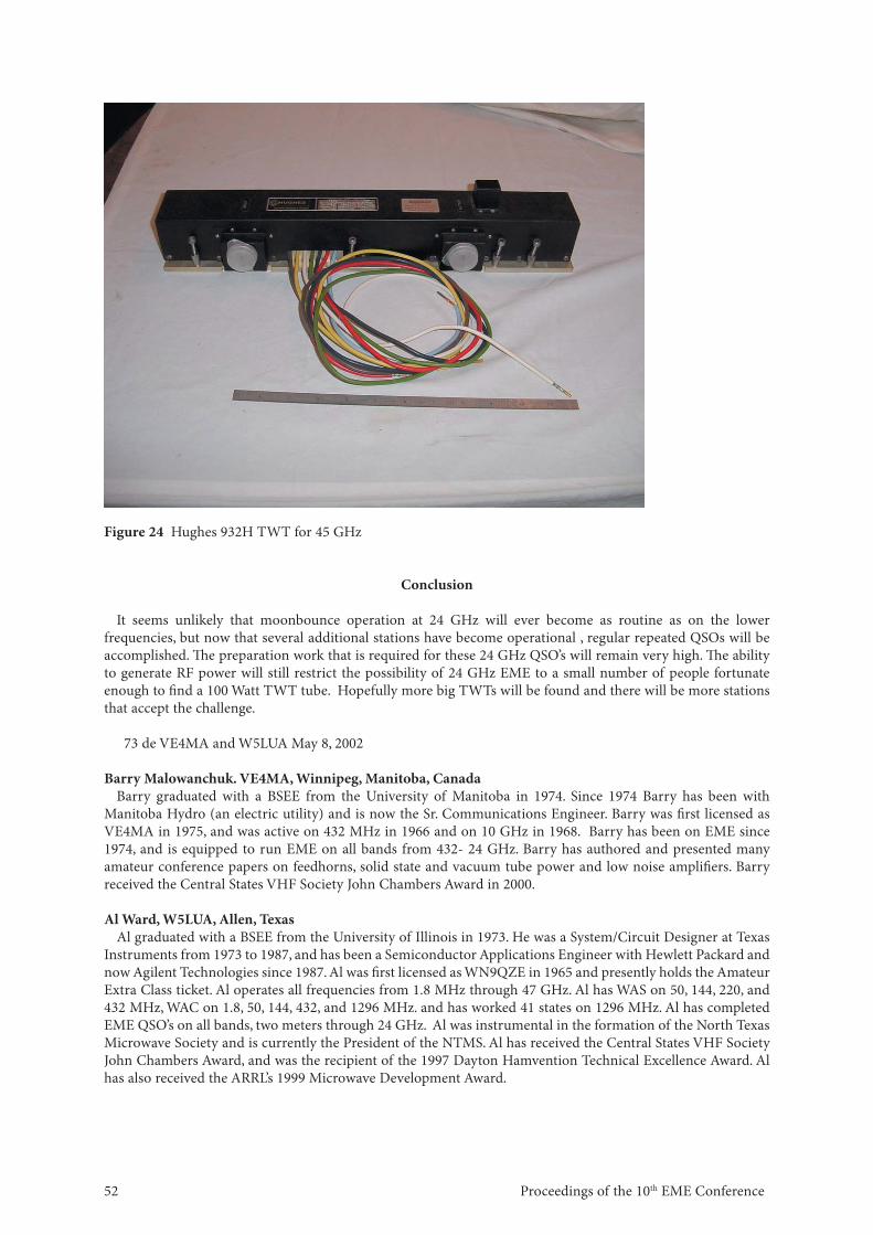
High powered TWT amplifi ers for 47 GHz are very scarce, but they are made for military satellite programs at 44.5 GHz. Tubes up to 250 Watts are shown in the Th ales (Th omson) catalog listings. Occasionally high power TWT tubes have been found on the surplus market. Al W5LUA has found a Hughes 932H 32 watt CW TWT (Figure 24) and Gary AD6FP has a 100 Watt unit designed for 45 GHz, which should work just fi ne on 47 GHz. Th e Hughes 932H is a dual suppressed collector type for higher effi ciency but unfortunately will require a little more power supply work. VE4MA has already achieved 9 watts output on 47 GHz with his 80 Watt 32-38 GHz Varian TWT.
Based on the use of a good 1.2 m off set dish and a 4.5 dB noise fi gure receiver 47 GHz EME QSO’s should be possible with 25 Watts at the feedhorn, but it will not be easy. I guess if it weren’t such a challenge, then everyone would be doing it!
Proceedings of the 10th EME Conference 52
Figure 24 Hughes 932H TWT for 45 GHz
Conclusion
It seems unlikely that moonbounce operation at 24 GHz will ever become as routine as on the lower frequencies, but now that several additional stations have become operational , regular repeated QSOs will be accomplished. Th e preparation work that is required for these 24 GHz QSO’s will remain very high. Th e ability to generate RF power will still restrict the possibility of 24 GHz EME to a small number of people fortunate enough to fi nd a 100 Watt TWT tube. Hopefully more big TWTs will be found and there will be more stations that accept the challenge.
73 de VE4MA and W5LUA May 8, 2002
Barry Malowanchuk. VE4MA, Winnipeg, Manitoba, CanadaBarry graduated with a BSEE from the University of Manitoba in 1974. Since 1974 Barry has been with
Manitoba Hydro (an electric utility) and is now the Sr. Communications Engineer. Barry was fi rst licensed as VE4MA in 1975, and was active on 432 MHz in 1966 and on 10 GHz in 1968. Barry has been on EME since 1974, and is equipped to run EME on all bands from 432- 24 GHz. Barry has authored and presented many amateur conference papers on feedhorns, solid state and vacuum tube power and low noise amplifi ers. Barry received the Central States VHF Society John Chambers Award in 2000.
Al Ward, W5LUA, Allen, TexasAl graduated with a BSEE from the University of Illinois in 1973. He was a System/Circuit Designer at Texas
Instruments from 1973 to 1987, and has been a Semiconductor Applications Engineer with Hewlett Packard and now Agilent Technologies since 1987. Al was fi rst licensed as WN9QZE in 1965 and presently holds the Amateur Extra Class ticket. Al operates all frequencies from 1.8 MHz through 47 GHz. Al has WAS on 50, 144, 220, and 432 MHz, WAC on 1.8, 50, 144, 432, and 1296 MHz. and has worked 41 states on 1296 MHz. Al has completed EME QSO’s on all bands, two meters through 24 GHz. Al was instrumental in the formation of the North Texas Microwave Society and is currently the President of the NTMS. Al has received the Central States VHF Society John Chambers Award, and was the recipient of the 1997 Dayton Hamvention Technical Excellence Award. Al has also received the ARRL’s 1999 Microwave Development Award.