Embed Size (px)
Citation preview
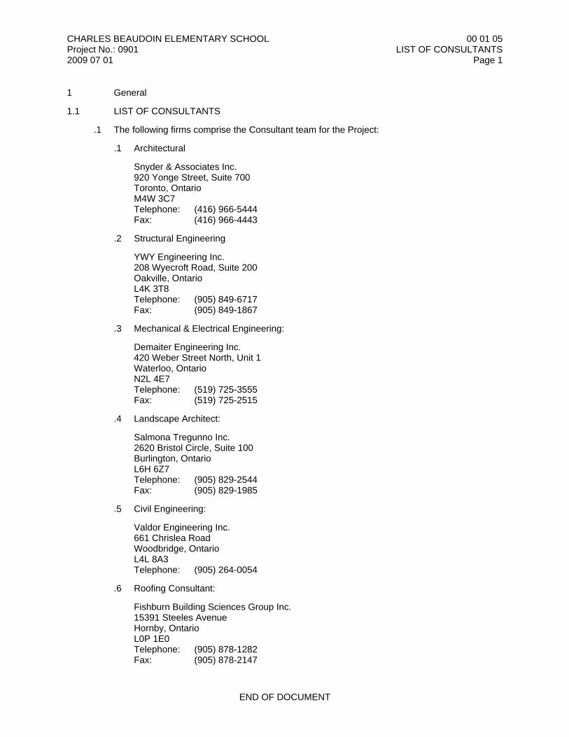
CHARLES BEAUDOIN ELEMENTARY SCHOOLProject No.: 09012009 07 01
00 01 05LIST OF CONSULTANTS
Page 1
1 General
1.1 LIST OF CONSULTANTS
.1 The following firms comprise the Consultant team for the Project:
.1 Architectural
Snyder & Associates Inc.920 Yonge Street, Suite 700Toronto, OntarioM4W 3C7Telephone: (416) 966-5444Fax: (416) 966-4443
.2 Structural Engineering
YWY Engineering Inc.208 Wyecroft Road, Suite 200Oakville, OntarioL4K 3T8Telephone: (905) 849-6717Fax: (905) 849-1867
.3 Mechanical & Electrical Engineering:
Demaiter Engineering Inc.420 Weber Street North, Unit 1Waterloo, OntarioN2L 4E7Telephone: (519) 725-3555Fax: (519) 725-2515
.4 Landscape Architect:
Salmona Tregunno Inc.2620 Bristol Circle, Suite 100Burlington, OntarioL6H 6Z7Telephone: (905) 829-2544Fax: (905) 829-1985
.5 Civil Engineering:
Valdor Engineering Inc.661 Chrislea RoadWoodbridge, OntarioL4L 8A3Telephone: (905) 264-0054
.6 Roofing Consultant:
Fishburn Building Sciences Group Inc.15391 Steeles AvenueHornby, OntarioL0P 1E0Telephone: (905) 878-1282Fax: (905) 878-2147
END OF DOCUMENT

CHARLES BEAUDOIN ELEMENTARY SCHOOLProject No.: 09012009 07 01
00 01 10TABLE OF CONTENTS
Page 1
PROCUREMENT AND CONTRACTING REQUIREMENTS GROUPDivision 00 - Procurement and Contracting RequirementsIntroductory Information00 01 05 List of Consultants00 01 10 Table of ContentsProcurement Requirements00 21 13 Instructions to Bidders00 41 03 Cost-Plus Fee Bid Form00 41 11 Stipulated Sum Subcontract Bid FormContracting Requirements00 52 03 Cost-Plus Agreement00 52 11 Subcontract Agreement00 61 11 Consent of Surety - Sample Form00 71 03 Cost-Plus Contracting Definitions00 71 11 Subcontracting Definitions00 72 03 General Conditions00 72 11 Subcontract Conditions00 73 03 Supplementary Conditions00 73 11 Supplementary Subcontract Conditions
SPECIFICATIONS GROUPGENERAL REQUIREMENTS SUBGROUPDivision 01 - General Requirements01 12 00 Multiple Contract Summary01 21 00 Allowances01 23 00 Alternatives01 25 00 Substitution Procedures01 26 00 Contract Modification Procedures01 31 00 Project Management and Coordination01 32 00 Construction Progress Documentation01 33 00 Submittal Procedures01 35 00 Special Procedures01 40 00 Quality Requirements01 50 00 Temporary Facilities and Controls01 60 00 Product Requirements01 71 00 Examination and Preparation Procedures01 73 00 Execution01 73 29 Cutting and Patching01 74 00 Cleaning and Waste Management01 76 00 Protecting Installed Construction01 77 00 Closeout Procedures 01 78 00 Closeout Submittals01 79 00 Demonstration and Training
FACILITY CONSTRUCTION SUBGROUPDivision 02 - Existing Conditions02 41 19 Selective Structure Demolition
Division 03 - Concrete03 10 00 Concrete Forming and Accessories03 20 00 Concrete Reinforcing03 30 00 Cast-In-Place Concrete03 35 00 Concrete Finishing03 41 13 Precast Concrete Hollow Core Planks03 41 23 Precast Concrete Stairs
CHARLES BEAUDOIN ELEMENTARY SCHOOLProject No.: 09012009 07 01
00 01 10TABLE OF CONTENTS
Page 2
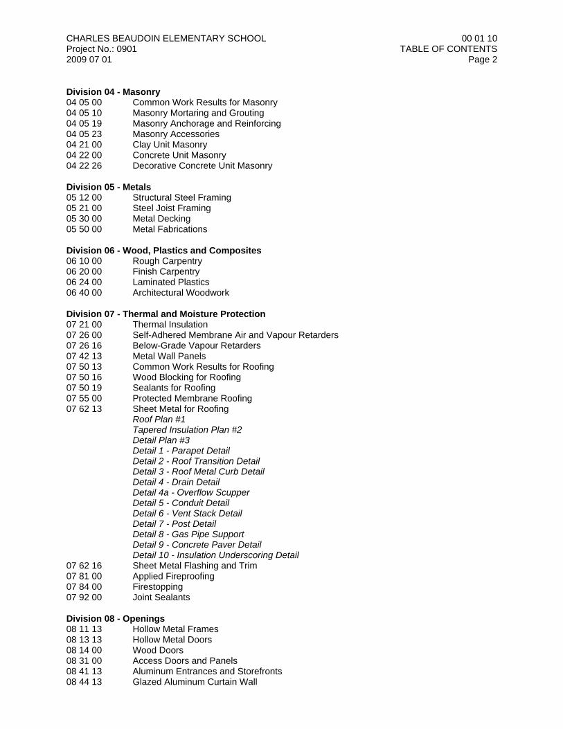
Division 04 - Masonry04 05 00 Common Work Results for Masonry04 05 10 Masonry Mortaring and Grouting04 05 19 Masonry Anchorage and Reinforcing04 05 23 Masonry Accessories04 21 00 Clay Unit Masonry04 22 00 Concrete Unit Masonry04 22 26 Decorative Concrete Unit Masonry
Division 05 - Metals05 12 00 Structural Steel Framing05 21 00 Steel Joist Framing05 30 00 Metal Decking05 50 00 Metal Fabrications
Division 06 - Wood, Plastics and Composites06 10 00 Rough Carpentry06 20 00 Finish Carpentry 06 24 00 Laminated Plastics06 40 00 Architectural Woodwork
Division 07 - Thermal and Moisture Protection07 21 00 Thermal Insulation07 26 00 Self-Adhered Membrane Air and Vapour Retarders07 26 16 Below-Grade Vapour Retarders07 42 13 Metal Wall Panels07 50 13 Common Work Results for Roofing07 50 16 Wood Blocking for Roofing07 50 19 Sealants for Roofing07 55 00 Protected Membrane Roofing07 62 13 Sheet Metal for Roofing
Roof Plan #1Tapered Insulation Plan #2Detail Plan #3Detail 1 - Parapet DetailDetail 2 - Roof Transition DetailDetail 3 - Roof Metal Curb DetailDetail 4 - Drain DetailDetail 4a - Overflow ScupperDetail 5 - Conduit DetailDetail 6 - Vent Stack DetailDetail 7 - Post DetailDetail 8 - Gas Pipe SupportDetail 9 - Concrete Paver DetailDetail 10 - Insulation Underscoring Detail
07 62 16 Sheet Metal Flashing and Trim07 81 00 Applied Fireproofing07 84 00 Firestopping07 92 00 Joint Sealants
Division 08 - Openings08 11 13 Hollow Metal Frames08 13 13 Hollow Metal Doors08 14 00 Wood Doors08 31 00 Access Doors and Panels08 41 13 Aluminum Entrances and Storefronts08 44 13 Glazed Aluminum Curtain Wall
CHARLES BEAUDOIN ELEMENTARY SCHOOLProject No.: 09012009 07 01
00 01 10TABLE OF CONTENTS
Page 3
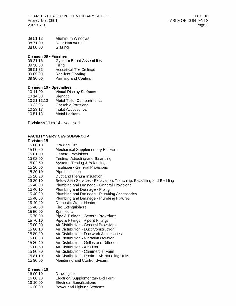
08 51 13 Aluminum Windows08 71 00 Door Hardware08 80 00 Glazing
Division 09 - Finishes09 21 16 Gypsum Board Assemblies09 30 00 Tiling09 51 23 Acoustical Tile Ceilings09 65 00 Resilient Flooring09 90 00 Painting and Coating
Division 10 - Specialties10 11 00 Visual Display Surfaces10 14 00 Signage10 21 13.13 Metal Toilet Compartments10 22 26 Operable Partitions10 28 13 Toilet Accessories10 51 13 Metal Lockers
Divisions 11 to 14 - Not Used
FACILITY SERVICES SUBGROUPDivision 1515 00 10 Drawing List15 00 50 Mechanical Supplementary Bid Form15 01 00 General Provisions15 02 00 Testing, Adjusting and Balancing15 02 50 Systems Testing & Balancing15 20 00 Insulation - General Provisions15 20 10 Pipe Insulation15 20 20 Duct and Plenum Insulation15 30 10 Below Slab Services - Excavation, Trenching, Backfilling and Bedding15 40 00 Plumbing and Drainage - General Provisions15 40 10 Plumbing and Drainage - Piping15 40 20 Plumbing and Drainage - Plumbing Accessories15 40 30 Plumbing and Drainage - Plumbing Fixtures15 40 40 Domestic Water Heaters15 40 50 Fire Extinguishers15 50 00 Sprinklers15 70 00 Pipe & Fittings - General Provisions15 70 10 Pipe & Fittings - Pipe & Fittings15 80 00 Air Distribution - General Provisions15 80 10 Air Distribution - Duct Construction15 80 20 Air Distribution - Ductwork Accessories15 80 30 Air Distribution - Vibration Isolation15 80 40 Air Distribution - Grilles and Diffusers15 80 50 Air Distribution - Air Filter15 80 80 Air Distribution - Commercial Fans15 81 10 Air Distribution - Rooftop Air Handling Units15 90 00 Monitoring and Control System
Division 1616 00 10 Drawing List16 00 20 Electrical Supplementary Bid Form16 10 00 Electrical Specifications16 20 00 Power and Lighting Systems
CHARLES BEAUDOIN ELEMENTARY SCHOOLProject No.: 09012009 07 01
00 01 10TABLE OF CONTENTS
Page 4
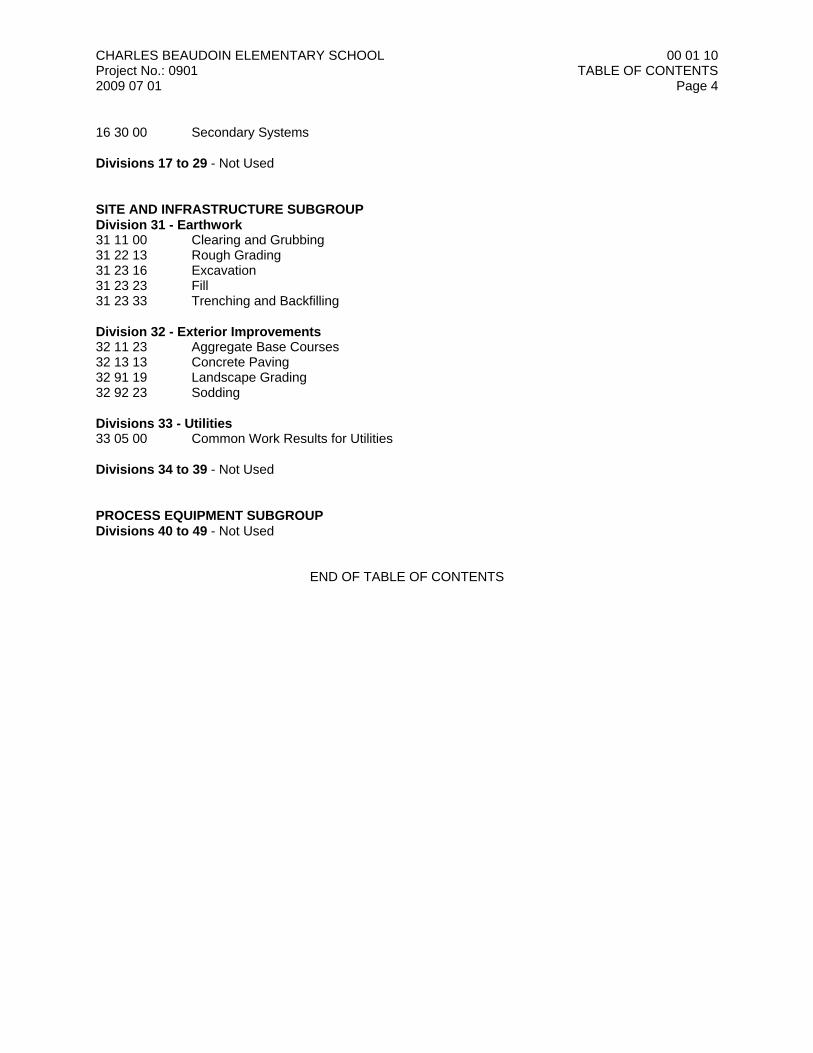
16 30 00 Secondary Systems
Divisions 17 to 29 - Not Used
SITE AND INFRASTRUCTURE SUBGROUPDivision 31 - Earthwork31 11 00 Clearing and Grubbing31 22 13 Rough Grading31 23 16 Excavation31 23 23 Fill31 23 33 Trenching and Backfilling
Division 32 - Exterior Improvements32 11 23 Aggregate Base Courses32 13 13 Concrete Paving32 91 19 Landscape Grading32 92 23 Sodding
Divisions 33 - Utilities33 05 00 Common Work Results for Utilities
Divisions 34 to 39 - Not Used
PROCESS EQUIPMENT SUBGROUPDivisions 40 to 49 - Not Used
END OF TABLE OF CONTENTS
CHARLES BEAUDOIN ELEMENTARY SCHOOLProject No.: 09012009 07 01
00 21 13INSTRUCTIONS TO BIDDERS
Page 1
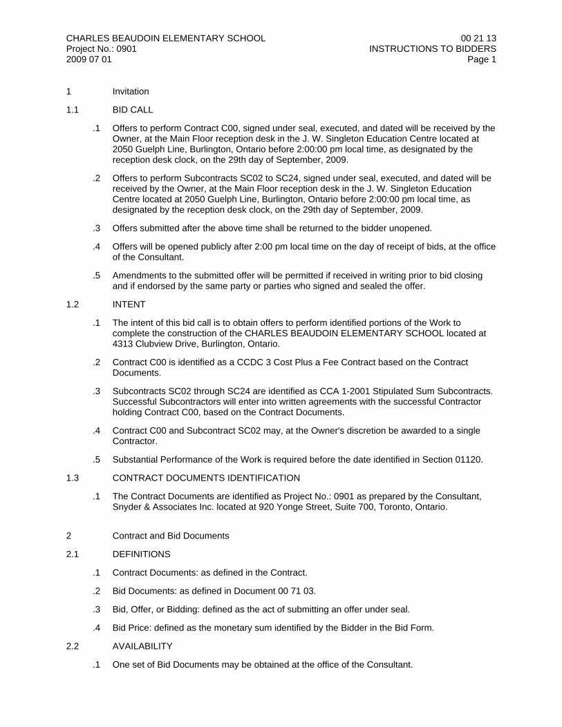
1 Invitation
1.1 BID CALL
.1 Offers to perform Contract C00, signed under seal, executed, and dated will be received by theOwner, at the Main Floor reception desk in the J. W. Singleton Education Centre located at2050 Guelph Line, Burlington, Ontario before 2:00:00 pm local time, as designated by thereception desk clock, on the 29th day of September, 2009.
.2 Offers to perform Subcontracts SC02 to SC24, signed under seal, executed, and dated will bereceived by the Owner, at the Main Floor reception desk in the J. W. Singleton EducationCentre located at 2050 Guelph Line, Burlington, Ontario before 2:00:00 pm local time, asdesignated by the reception desk clock, on the 29th day of September, 2009.
.3 Offers submitted after the above time shall be returned to the bidder unopened.
.4 Offers will be opened publicly after 2:00 pm local time on the day of receipt of bids, at the officeof the Consultant.
.5 Amendments to the submitted offer will be permitted if received in writing prior to bid closingand if endorsed by the same party or parties who signed and sealed the offer.
1.2 INTENT
.1 The intent of this bid call is to obtain offers to perform identified portions of the Work tocomplete the construction of the CHARLES BEAUDOIN ELEMENTARY SCHOOL located at4313 Clubview Drive, Burlington, Ontario.
.2 Contract C00 is identified as a CCDC 3 Cost Plus a Fee Contract based on the ContractDocuments.
.3 Subcontracts SC02 through SC24 are identified as CCA 1-2001 Stipulated Sum Subcontracts. Successful Subcontractors will enter into written agreements with the successful Contractorholding Contract C00, based on the Contract Documents.
.4 Contract C00 and Subcontract SC02 may, at the Owner's discretion be awarded to a singleContractor.
.5 Substantial Performance of the Work is required before the date identified in Section 01120.
1.3 CONTRACT DOCUMENTS IDENTIFICATION
.1 The Contract Documents are identified as Project No.: 0901 as prepared by the Consultant,Snyder & Associates Inc. located at 920 Yonge Street, Suite 700, Toronto, Ontario.
2 Contract and Bid Documents
2.1 DEFINITIONS
.1 Contract Documents: as defined in the Contract.
.2 Bid Documents: as defined in Document 00 71 03.
.3 Bid, Offer, or Bidding: defined as the act of submitting an offer under seal.
.4 Bid Price: defined as the monetary sum identified by the Bidder in the Bid Form.
2.2 AVAILABILITY
.1 One set of Bid Documents may be obtained at the office of the Consultant.
CHARLES BEAUDOIN ELEMENTARY SCHOOLProject No.: 09012009 07 01
00 21 13INSTRUCTIONS TO BIDDERS
Page 2
.2 Return Bid Documents complete, undamaged, unmarked and reusable within 14 days of bidsubmission.
.3 Bid Documents are made available only for the purpose of obtaining offers for this project.Their use does not confer a license or grant for other purposes.
2.3 EXAMINATION
.1 Bid Documents may be viewed at the office of the Consultant.
.2 Upon receipt of Bid Documents verify that documents are complete; notify Consultant shouldthe documents be incomplete.
.3 Immediately notify the Consultant upon finding discrepancies or omissions in the BidDocuments.
2.4 QUERIES AND ADDENDA
.1 Direct queries in writing by Fax to: Anil Gokarn at Snyder & Associates Inc., Fax: (416) 966-4443.
.2 Addenda may be issued during the bidding period. All addenda become part of the ContractDocuments. Include costs in Bid Price.
.3 Verbal answers are only binding when confirmed by written addenda.
.4 Clarifications requested by bidders must be in writing not less than 4 Working Days before dateset for receipt of bids. The reply will be in the form of an addendum, a copy of which will beforwarded to known bidders no later than 2 Working Days before receipt of bids.
2.5 PRODUCT / SYSTEM OPTIONS
.1 Where Bid Documents stipulate a particular Product, requests for substitutions will not beconsidered by the Consultant less than seven days before receipt of bids.
.2 When a request to substitute a Product is made, the Consultant may approve the substitutionand will issue an Addendum to known bidders.
.3 When requesting a substitution to specified Products, include any changes required in theWork to accommodate such substitutions. A later claim by the bidder for an addition to theContract Price resulting from changes in the Work necessitated by use of substituted Productswill not be considered.
.4 Product or system substitutions recommended by Bidders at the time of receipt of bids may beconsidered by Consultant if submitted as an attachment to the Bid Form. Substitutions notapproved in writing by the Consultant prior to the receipt of bids shall not be included in thebase Bid Price. Refer to Section 01 25 00.
.5 Requests for Product or system substitutions submitted with the Bid Form will be evaluatedand will be either included in, or excluded from, the Contract. The Consultant will be the solejudge as to their acceptability.
.6 Provide sufficient information to enable the Consultant to determine acceptability of suchProduct or system substitutions.
.7 Provide complete information on required revisions to other work to accommodate eachProduct or system substitution, the dollar amount of additions to or reductions from the BidPrice, including revisions to other work.
.8 Unless requests for substitutions are submitted prior to, or as part of the bid submission, andsubsequently accepted, provide the specified Products.
CHARLES BEAUDOIN ELEMENTARY SCHOOLProject No.: 09012009 07 01
00 21 13INSTRUCTIONS TO BIDDERS
Page 3
.9 Prior approval to submit requests for substitutions is not required.
3 Site Assessment
3.1 PRE-BID SITE EXAMINATION
.1 A mandatory visit to the Place of the Work has been arranged for the following listed bidderson September 22, 2009 at 3:30 pm local time:.1 Contract C00 - Contractor..2 Subcontract SC02 - General..3 Subcontract SC04 - Mechanical..4 Subcontract SC05 - Electrical.
.2 Meet in the existing school's Main Office.
.3 Bidders visiting the Place of the Work will be required to sign in at the Main Office and obtain avisitor badge. Upon completion of visit, sign out and return visitor badge to Owner.
.4 Bidders visiting the Place of the Work will be required to be accompanied at all times by arepresentative of the Owner and the Consultant.
.5 No claims for extra payment to the successful Contractor will be allowed for the execution ofadditional work or difficulties encountered due to conditions at the Place of the Work whichwere visible or reasonably inferred from an examination of the Place of the Work prior toreceipt of the Bids.
4 Qualifications
4.1 SUBCONTRACTORS
.1 The Owner reserves the right to reject a proposed Subcontractor for reasonable cause. Uponsuch rejection, the bidder will be required to propose an alternate subcontractor with a resultingchange to the Bid Price. This change can effect the status of the low bid, and may result in adifferent bid becoming low.
.2 Refer to CCDC 3-1998, GC 3.8 - Subcontractor and Supplier; and CCA 1-2001, SCC 3.4 -Sub-subcontractors.
5 Bid Submission
5.1 BID INELIGIBILITY
.1 Bids that are unsigned, improperly signed or sealed, conditional, illegible, obscure, containarithmetical errors, erasures, alterations, or irregularities of any kind shall, at the discretion ofthe Owner, be declared informal.
.2 Bids with Bid Forms and enclosures which are missing, incomplete or improperly preparedshall, at the discretion of the Owner, be declared informal.
.3 Bids that fail to include the consent of surety (where applicable) or WSIB requirements shall, atthe discretion of the Owner, be declared informal.
.4 Bids based upon prices seeming to be so unbalanced as to adversely affect the interests of theOwner shall, at the discretion of the Owner, be declared informal.
.5 Bids based upon an unreasonable period of time for completion of the Work shall, at thediscretion of the Owner, be declared informal.
CHARLES BEAUDOIN ELEMENTARY SCHOOLProject No.: 09012009 07 01
00 21 13INSTRUCTIONS TO BIDDERS
Page 4
.6 Bids are by invitation only from lists of preselected bidders. Bids received from unsolicitedbidders shall be returned unopened.
5.2 SUBMISSIONS
.1 Bidders shall be solely responsible for the delivery of their bids in the manner and timeprescribed.
.2 Submit one copy of the properly executed offer on the Bid Forms provided, together with therequired appendices in a closed opaque envelope, clearly identified with:.1 the Project name and address,.2 the Owner's name and address,.3 the Bidder's name and address, .4 the Owner's Tender Number, and.5 the relevant Contract or Subcontract number and title.
.3 Bidders wishing to submit prices for more than one Contract or Subcontract may do so onseparate bid forms, submitted separately as described above. Do not combine informationpertaining to multiple Contracts or Subcontracts on a single bid form.
.4 Subcontract bids must include the appropriate reference to the Subcontract number and title. Refer to Section 01 12 00 for the summary of Subcontract numbers and titles.
.5 An abstract of submitted bids will be made available to bidders following bid opening.
6 Bid Enclosures and Requirements
6.1 CONSENT OF SURETY
.1 Subcontractors who are required to acquire bonding shall submit with the Bid Form a Consentof Surety, stating that the identified surety is willing to supply the Performance Bond andLabour & Materials Payment Bond required. Refer to Document 00 61 11.
.2 Include the cost of the Consent of Surety in the Bid Price.
6.2 PERFORMANCE ASSURANCE
.1 Specified Subcontractors will be required to acquire and submit a Performance Bond and aLabour & Materials Payment Bond as described in the Supplementary Subcontract Conditions.
.2 Include the cost of bonds in the Bid Price.
6.3 WORKPLACE SAFETY AND INSURANCE BOARD
.1 Provide a signed confirmation from the Workplace Safety and Insurance Board (WSIB) that, atthe date of the letter, the bidder maintains an account with the WSIB, and is in good standing.
6.4 TAXES
.1 Unless specifically excluded by the Contract, include all applicable government taxes in thebase Bid Price.
.2 The General Conditions of the Contract specifically excludes Value Added Taxes, such as thefederal government's Goods and Services Tax, from the Contract Price.
.3 Refer to Supplementary Conditions for inclusion of taxes and procedures for tax rebate claimsby the Owner.
CHARLES BEAUDOIN ELEMENTARY SCHOOLProject No.: 09012009 07 01
00 21 13INSTRUCTIONS TO BIDDERS
Page 5
6.5 BID FORM REQUIREMENTS
.1 The bidder, in submitting an offer, agrees to complete the Work by the date indicated in theContract Documents.
.2 The Owner requires that the Work be completed as quickly and expeditiously as possible.
6.6 BID SIGNING
.1 Sign and seal the Bid Form prior to submission using the most appropriate of the followingmethods:.1 Sole Proprietorship: signature of sole proprietor in the presence of a witness who will also
sign. Insert the words "Sole Proprietor" under the signature..2 Partnership: signature of all partners in the presence of a witness who will also sign..3 Limited Company: signature of a duly authorized signing officer(s) in their normal
signatures. Insert the officer's capacity in which the signing officer acts, under eachsignature. Affix the corporate seal. If the bid is signed by officials other than the Presidentand Secretary of the company, or the President-Secretary-Treasurer of the company, acopy of the by-law resolution of the Board of Directors authorizing them to do so, mustalso be submitted with the Bid in the Bid envelope.
.4 Joint Venture: each party of the joint venture shall execute the Bid under their respectiveseals in a manner appropriate to such party as described above, similar to therequirements of a Partnership.
6.7 APPENDICES TO THE BID FORM
.1 The following appendix to the Bid Form must be submitted with the Bid:.1 Appendix A - Bid Documents: a complete listing of all documents and information issued
by which the Bid Price was derived.
7 Offer Acceptance Or Rejection
7.1 DURATION OF OFFER
.1 Bids shall remain open to acceptance and shall be irrevocable for a period of 60 days after thebid closing.
7.2 ACCEPTANCE OF OFFER
.1 The Owner reserves the right to accept or reject any or all offers.
.2 The Owner may decide to award Contract C00 and Subcontract SC02 to the same bidder. Inthis instance, the lowest bidder would be determined by the aggregate sum of the Contractor'sFee identified for Contract C00 and the Subcontract Price for Subcontract SC02.
.3 The Owner reserves the right to negotiate with the lowest acceptable bidder to verify their Bid,undertake value engineering and consider the benefit of dividing the Work into multipleSubcontracts for the different Phases. The Owner may, at their sole discretion, reject a bidduring such negotiations if sufficient information and cost breakdowns are not forthcomingwithin a reasonable time frame.
.4 After acceptance by the Owner, the Consultant, on behalf of the Owner, will issue to thesuccessful bidder a written bid acceptance.
.5 After a bid has been accepted, all rejected bids will be returned to the respective bidders withsubmitted bid securities and other requested enclosures.
END OF DOCUMENT
DOCUMENT 00 41 03 1
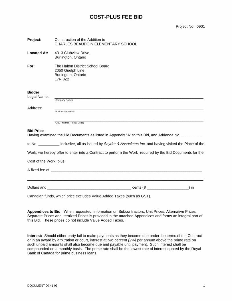
COST-PLUS FEE BIDProject No.: 0901
Project: Construction of the Addition toCHARLES BEAUDOIN ELEMENTARY SCHOOL
Located At: 4313 Clubview Drive, Burlington, Ontario
For: The Halton District School Board2050 Guelph Line,Burlington, OntarioL7R 3Z2
BidderLegal Name: _______________________________________________________________________
(Company Name)
Address: _______________________________________________________________________(Business Address)
_______________________________________________________________________(City, Province, Postal Code)
Bid PriceHaving examined the Bid Documents as listed in Appendix "A" to this Bid, and Addenda No. __________
to No. __________ inclusive, all as issued by Snyder & Associates Inc. and having visited the Place of the
Work; we hereby offer to enter into a Contract to perform the Work required by the Bid Documents for the
Cost of the Work, plus:
A fixed fee of: ________________________________________________________________________
____________________________________________________________________________________
Dollars and ________________________________________ cents ($ ____________________) in
Canadian funds, which price excludes Value Added Taxes (such as GST).
Appendices to Bid: When requested, information on Subcontractors, Unit Prices, Alternative Prices,Separate Prices and Itemized Prices is provided in the attached Appendices and forms an integral part ofthis Bid. These prices do not include Value Added Taxes.
Interest: Should either party fail to make payments as they become due under the terms of the Contractor in an award by arbitration or court, interest at two percent (2%) per annum above the prime rate onsuch unpaid amounts shall also become due and payable until payment. Such interest shall becompounded on a monthly basis. The prime rate shall be the lowest rate of interest quoted by the RoyalBank of Canada for prime business loans.
DOCUMENT 00 41 03 2
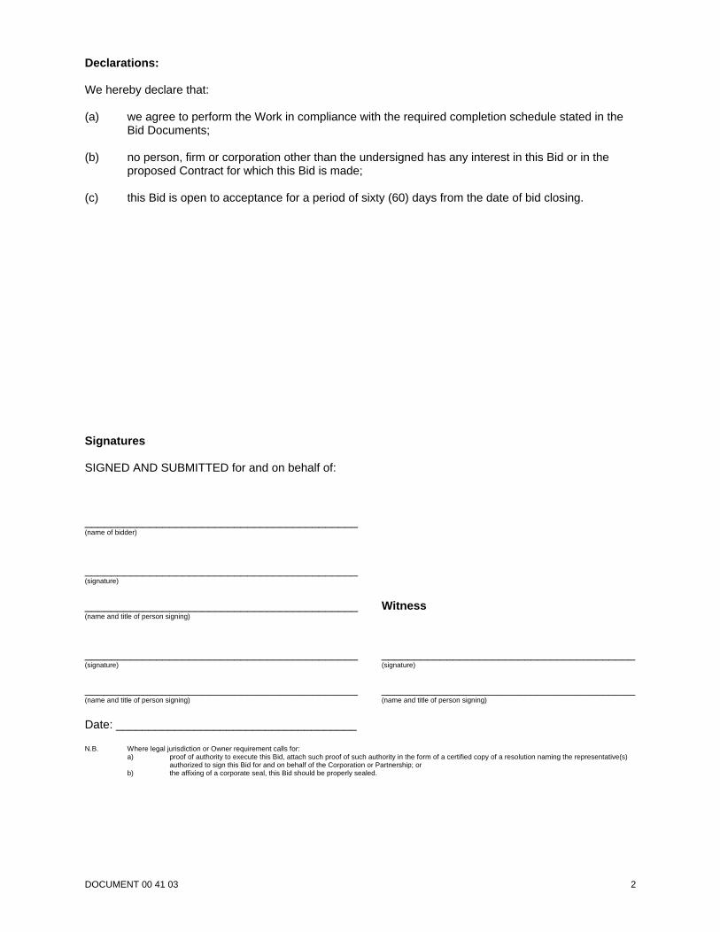
Declarations:
We hereby declare that:
(a) we agree to perform the Work in compliance with the required completion schedule stated in theBid Documents;
(b) no person, firm or corporation other than the undersigned has any interest in this Bid or in theproposed Contract for which this Bid is made;
(c) this Bid is open to acceptance for a period of sixty (60) days from the date of bid closing.
Signatures
SIGNED AND SUBMITTED for and on behalf of:
__________________________________________(name of bidder)
__________________________________________(signature)
__________________________________________ Witness(name and title of person signing)
__________________________________________ _______________________________________(signature) (signature)
__________________________________________ _______________________________________(name and title of person signing) (name and title of person signing)
Date: _____________________________________
N.B. Where legal jurisdiction or Owner requirement calls for:a) proof of authority to execute this Bid, attach such proof of such authority in the form of a certified copy of a resolution naming the representative(s)
authorized to sign this Bid for and on behalf of the Corporation or Partnership; orb) the affixing of a corporate seal, this Bid should be properly sealed.
DOCUMENT 00 41 03 3
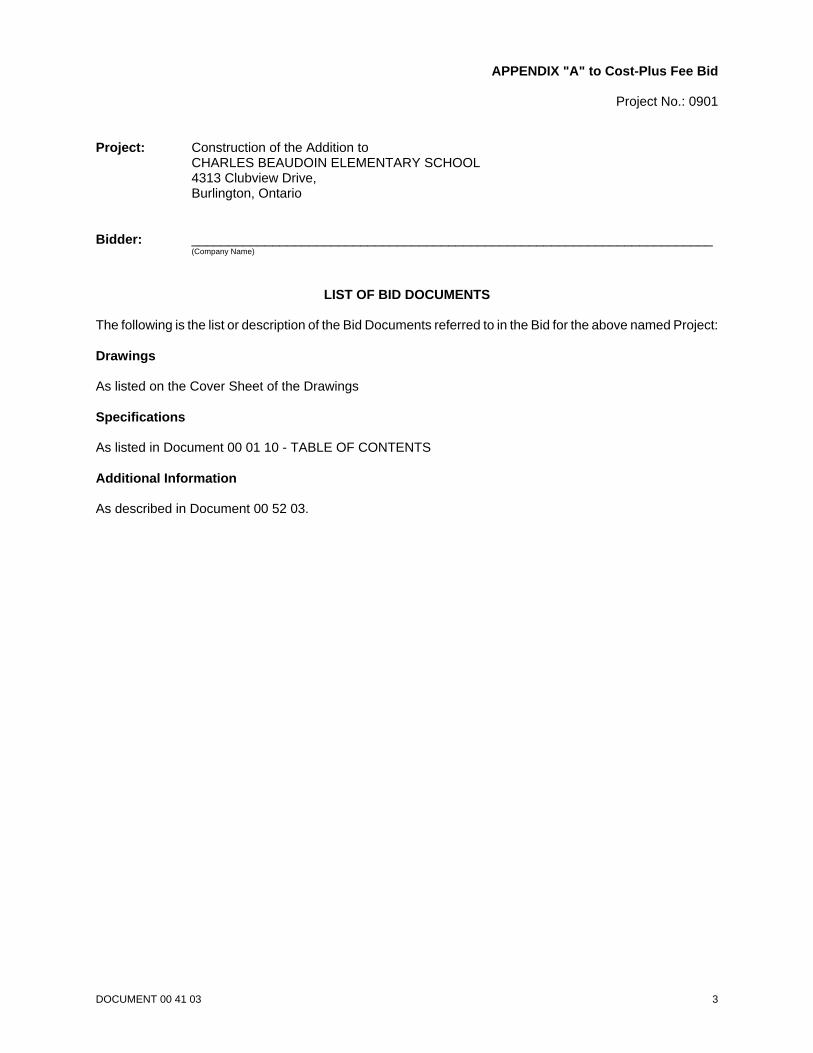
APPENDIX "A" to Cost-Plus Fee Bid
Project No.: 0901
Project: Construction of the Addition to CHARLES BEAUDOIN ELEMENTARY SCHOOL4313 Clubview Drive, Burlington, Ontario
Bidder: _______________________________________________________________________(Company Name)
LIST OF BID DOCUMENTS
The following is the list or description of the Bid Documents referred to in the Bid for the above named Project:
Drawings
As listed on the Cover Sheet of the Drawings
Specifications
As listed in Document 00 01 10 - TABLE OF CONTENTS
Additional Information
As described in Document 00 52 03.
DOCUMENT 00 41 11 1
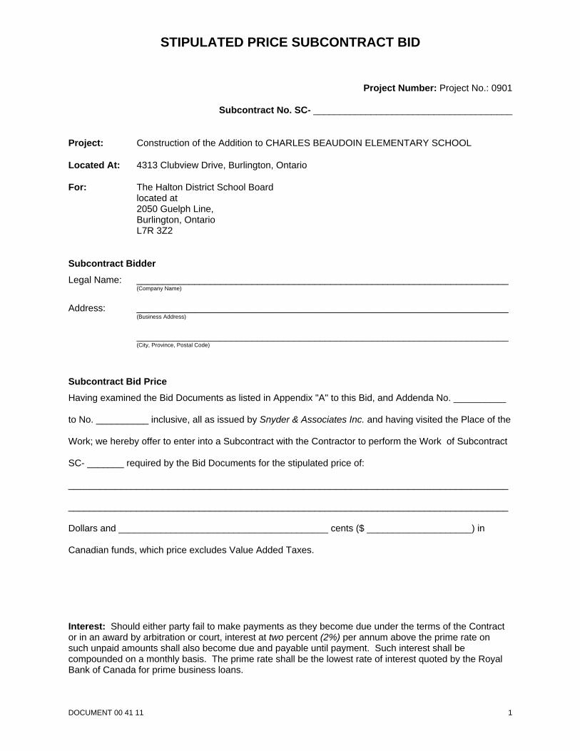
STIPULATED PRICE SUBCONTRACT BID
Project Number: Project No.: 0901
Subcontract No. SC- ______________________________________
Project: Construction of the Addition to CHARLES BEAUDOIN ELEMENTARY SCHOOL
Located At: 4313 Clubview Drive, Burlington, Ontario
For: The Halton District School Boardlocated at 2050 Guelph Line, Burlington, Ontario L7R 3Z2
Subcontract BidderLegal Name: _______________________________________________________________________
(Company Name)
Address: _______________________________________________________________________(Business Address)
_______________________________________________________________________(City, Province, Postal Code)
Subcontract Bid PriceHaving examined the Bid Documents as listed in Appendix "A" to this Bid, and Addenda No. __________
to No. __________ inclusive, all as issued by Snyder & Associates Inc. and having visited the Place of the
Work; we hereby offer to enter into a Subcontract with the Contractor to perform the Work of Subcontract
SC- _______ required by the Bid Documents for the stipulated price of:
____________________________________________________________________________________
____________________________________________________________________________________
Dollars and ________________________________________ cents ($ ____________________) in
Canadian funds, which price excludes Value Added Taxes.
Interest: Should either party fail to make payments as they become due under the terms of the Contractor in an award by arbitration or court, interest at two percent (2%) per annum above the prime rate onsuch unpaid amounts shall also become due and payable until payment. Such interest shall becompounded on a monthly basis. The prime rate shall be the lowest rate of interest quoted by the RoyalBank of Canada for prime business loans.
DOCUMENT 00 41 11 2
Declarations:
We hereby declare that:
(a) we agree to perform the Subcontract Work in compliance with the required completion schedulestated in the Bid Documents, or if no schedule is stated, to attain Substantial Performance of theWork within __________ weeks from commencement of the Work;
(b) no person, firm or corporation other than the undersigned has any interest in this Bid or in theproposed Contract for which this Bid is made;
(c) we agree to enter into a Subcontract Agreement, as identified in the Contract Documents, with thesuccessful Contractor;
(d) this Bid is open to acceptance for a period of sixty (60) days from the date of bid closing.
Signatures
SIGNED AND SUBMITTED for and on behalf of:
__________________________________________(name of bidder)
__________________________________________(signature)
__________________________________________ Witness(name and title of person signing)
__________________________________________ _______________________________________(signature) (signature)
__________________________________________ _______________________________________(name and title of person signing) (name and title of person signing)
Date: _____________________________________
N.B. Where legal jurisdiction or Owner requirement calls for:a) proof of authority to execute this Bid, attach such proof of such authority in the form of a certified copy of a resolution naming the representative(s)
authorized to sign this Bid for and on behalf of the Corporation or Partnership; orb) the affixing of a corporate seal, this Bid should be properly sealed.
DOCUMENT 00 41 11 3
APPENDIX "A" to Stipulated Price Bid
Project Number: Project No.: 0901
Subcontract No. SC- ______________________________________
Project: Construction of the Addition to CHARLES BEAUDOIN ELEMENTARY SCHOOL4313 Clubview Drive, Burlington, Ontario
SubcontractBidder: _______________________________________________________________________
(Company Name)
LIST OF BID DOCUMENTS
The following is the list or description of the Bid Documents referred to in the Bid for the above named Project:
Drawings
As listed on the Cover Sheet of the Drawings.
Specifications
As listed in Document 00 01 10 - TABLE OF CONTENTS.
Additional Information
As described in Document 00 52 11.
CHARLES BEAUDOIN ELEMENTARY SCHOOLProject No.: 09012009 07 01
00 52 03COST-PLUS AGREEMENT
Page 1
1 General
1.1 AGREEMENT
.1 The CCDC 3-1998 Cost Plus Contract, as amended below, forms the basis of Agreementbetween the Owner and the Contractor.
1.2 AMENDMENTS TO THE AGREEMENT
.1 Article A-4 - Cost of the Work.1 Delete Paragraph A-4.1 in its entirety and replace with the following: "The Cost of the
Work, which excludes Value Added Taxes, shall be comprised of the stipulated sum costsof subsequently awarded Subcontracts, as nominated by the Owner, and the following:.1 deposits lost;.2 the costs to the Contractor that result from any Subcontractor's or Supplier's
insolvency or failure to perform;.3 royalties, patent license fees and damages for infringement of patents and cost of
defending suits therefor subject always to the Contractor's obligations to indemnifythe Owner as provided in paragraph 10.3.1 of GC 10.3 - PATENT FEES;
.4 losses and expenses sustained by the Contractor for matters which are the subjectof insurance under the policies prescribed in GC 11.1 - INSURANCE when suchlosses and expenses are not recoverable because the amounts are in excess ofcollectible amounts or within the deductible amounts;
.5 legal costs, incurred by the Contractor, in relation to the performance of the Workprovided that they are not caused by negligent acts or omissions of the Contractorand the Work is performed in accordance with the Contract Documents; and
.6 the cost of auditing when requested by the Owner.Notwithstanding the foregoing and any provisions contained in the General Conditions ofthe Contract, it is the intention of the parties that the Cost of the Work referred to hereinshall cover and include any and all contingencies other than those which are the result ofor occasioned by any failure on the part of the Contractor to exercise reasonable care anddiligence in the Contractor's attention to the Work. Any cost due to failure on the part ofthe Contractor to exercise reasonable care and diligence in the Contractor's attention tothe Work shall be borne by the Contractor."
.2 Article A-5 - Contractor’s Fee.1 Delete Paragraph A-5.1.1 in its entirety.
.3 Article A-6 - Contract Price.1 Delete Paragraph A-6.2 in its entirety.
.4 Article A-7 - Payment.1 Revise Subparagraph A-7.1.1 to insert the phrase "... make progress payments to
Contractor subject to GC 5.4 - Progress Payment...".
END OF DOCUMENT
CHARLES BEAUDOIN ELEMENTARY SCHOOLProject No.: 09012009 07 01
00 52 11SUBCONTRACT AGREEMENT
Page 1
1 General
1.1 AGREEMENT
.1 The CCA 1-2001 Stipulated Price Subcontract, as amended below, forms the basis ofAgreement between the Contractor and the Subcontractor.
1.2 AMENDMENTS TO THE AGREEMENT
.1 Delete Article 1B in its entirety.
.2 Delete Article 2B in its entirety.
.3 Delete Article 3B in its entirety.
.4 Article 5 - SUBCONTRACT PRICE, delete Paragraph 5.5 in its entirety.
.5 Article 6 - PAYMENT, Paragraph 6.2, Third Sentence; revise to read as follows: "TheContractor shall pay the Subcontractor, in accordance with the payment procedures requiredby the Contract Documents, no later than thirty (30) days after the date of the Consultant'scertificate of payment, 90 percent of the amount applied for or such other amount as theConsultant determines to be properly due."
.6 Article 6 - PAYMENT, Paragraph 6.4; revise to read as follows: "... and for which theContractor or Owner might in any way be held responsible ..."
.7 Article 6 - PAYMENT, Paragraph 6.4; delete Subparagraph 6.4.2 in its entirety.
.8 Article 6 - PAYMENT, Paragraph 6.5; revise Subparagraph 6.5.1 to read as follows: "... therate of interest quoted by the Bank of Canada."
END OF DOCUMENT
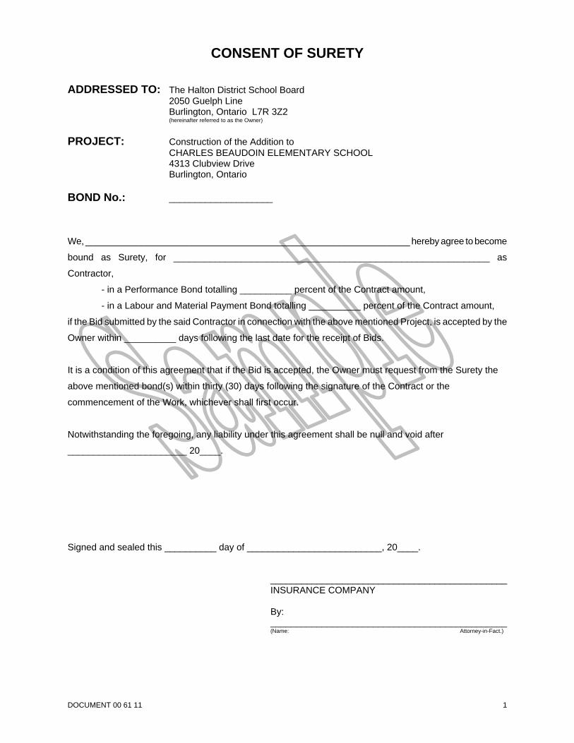
DOCUMENT 00 61 11 1
CONSENT OF SURETY
ADDRESSED TO: The Halton District School Board2050 Guelph LineBurlington, Ontario L7R 3Z2(hereinafter referred to as the Owner)
PROJECT: Construction of the Addition toCHARLES BEAUDOIN ELEMENTARY SCHOOL4313 Clubview DriveBurlington, Ontario
BOND No.: ____________________
We, ________________________________________________________________ hereby agree to become
bound as Surety, for _____________________________________________________________ as
Contractor,
- in a Performance Bond totalling __________ percent of the Contract amount,
- in a Labour and Material Payment Bond totalling __________ percent of the Contract amount,
if the Bid submitted by the said Contractor in connection with the above mentioned Project, is accepted by the
Owner within __________ days following the last date for the receipt of Bids.
It is a condition of this agreement that if the Bid is accepted, the Owner must request from the Surety the
above mentioned bond(s) within thirty (30) days following the signature of the Contract or the
commencement of the Work, whichever shall first occur.
Notwithstanding the foregoing, any liability under this agreement shall be null and void after
_______________________ 20____.
Signed and sealed this __________ day of __________________________, 20____.
______________________________________________INSURANCE COMPANY
By:______________________________________________(Name: Attorney-in-Fact.)
CHARLES BEAUDOIN ELEMENTARY SCHOOLProject No.: 09012009 07 01
00 71 03COST-PLUS CONTRACTING DEFINITIONS
Page 1
1 General
1.1 AGREEMENT
.1 The CCDC 3-1998 Cost Plus Contract, includes the Definitions of specific words and terms.
1.2 SUPPLEMENTARY DEFINITIONS
.1 Amend Definition 2 - Contract Documents by inserting the words "in writing" after the words"agreed upon".
.2 Amend Definition 14 - Contractor's Fee by adding the following: "... and including amounts forall overhead and profit, bond and insurance premiums, and any costs for labour and Productsrequired by the Contractor to undertake portions of the Work identified in the ContractDocuments and not included in an Owner-nominated Subcontract."
.3 Delete Definition 16 - Guaranteed Maximum Price in its entirety.
.4 Add a new Definition for Bid Documents, as follows: "The Bid Documents shall consist of theContract Documents, Instructions to Bidders, Geotechnical Investigation Reports, Bid Form,and other information issued for the benefit of bidders."
.5 Add a new Definition for Make Good as follows: "Make Good means to restore new or existingwork after being damaged, cut or patched. Use materials identical to the original materials,with visible surfaces matching the appearance of the original surfaces in all details, and with noapparent junctions between new and original surfaces."
END OF DOCUMENT
CHARLES BEAUDOIN ELEMENTARY SCHOOLProject No.: 09012009 07 01
00 71 11SUBCONTRACTING DEFINITIONS
Page 1
1 General
1.1 AGREEMENT
.1 The CCA 1-2001 Stipulated Price Subcontract includes the Definitions of specific words andterms.
1.2 SUUPLEMENTARY SUBCONTRACT DEFINITIONS
.1 Add a new Definition for Make Good as follows: "Make Good means to restore new or existingwork after being damaged, cut or patched. Use materials identical to the original materials,with visible surfaces matching the appearance of the original surfaces in all details, and with noapparent junctions between new and original surfaces."
END OF DOCUMENT
CHARLES BEAUDOIN ELEMENTARY SCHOOLProject No.: 09012009 07 01
00 72 03GENERAL CONDITIONS
Page 1
1 General
1.1 GENERAL CONDITIONS
.1 CCDC 3 - 1998, The General Conditions of the Cost Plus Contract is the General Conditionsbetween the Owner and Contractor.
1.2 SUPPLEMENTARY CONDITIONS
.1 Refer to Supplementary Conditions for amendments and supplements to the GeneralConditions.
END OF DOCUMENT
CHARLES BEAUDOIN ELEMENTARY SCHOOLProject No.: 09012009 07 01
00 72 11SUBCONTRACT CONDITIONS
Page 1
1 General
1.1 GENERAL CONDITIONS
.1 CCA 1-2001, The Subcontract Conditions of the Stipulated Price Subcontract are theSubcontract Conditions between the Contractor and the Subcontractors.
1.2 SUPPLEMENTARY CONDITIONS
.1 Refer to Supplementary Subcontract Conditions for amendments and supplements to theSubcontract Conditions.
END OF DOCUMENT
CHARLES BEAUDOIN ELEMENTARY SCHOOLProject No.: 09012009 07 01
00 73 03SUPPLEMENTARY CONDITIONS
Page 1
1 Supplements to General Conditions
1.1 GC 1.1 - CONTRACT DOCUMENTS
.1 Revise Paragraph 1.1.7 by adding the following sentences: "The location of fixtures, outlets,conduit, piping and any other locations shown or specified but not dimensioned shall beconsidered approximate. The actual location shall be as approved by the Consultant and asrequired to suit job conditions.”
1.2 GC 2.2 - ROLE OF THE CONSULTANT
.1 Add new Subparagraph 2.2.7.1 as follows: "Verbal instructions, regardless of the source, willnot be binding on the parties to the Contract, unless otherwise confirmed in writing by theOwner or the Consultant ."
1.3 GC 2.4 - DEFECTIVE WORK
.1 Add new Subparagraph 2.4.1.1 as follows: "Where defective work or work not performed asprovided in the Contract Documents is the responsibility of a Subcontractor or Supplier, theContractor shall require the responsible Subcontractor or Supplier to Make Good the defectivework or work not performed as provided in the Contract Documents so as to conform with theContract Documents."
1.4 GC 3.2 - CONSTRUCTION BY OWNER
.1 Delete Paragraph 3.2.2 in its entirety.
.2 Add new Subparagraph 3.2.3.5 as follows: "Assume overall responsibility for the separatecontractors and Owner's own forces and for compliance with applicable health andconstruction safety legislation at the Place of the Work".
.3 Add new Subparagraph 3.2.3.6 as follows: "The Owner will notify the Contractor no later than2 Working Days prior to any other contractor or their own forces being on site. The Contractorwill make all necessary arrangements to accommodate access and maintain compliance withapplicable health and construction safety legislation at the Place of the Work".
1.5 GC 3.5 - CONSTRUCTION SCHEDULE
.1 Add new Paragraph 3.5.2 as follows: "Where portions of the Work are performed by Subcontractors or Suppliers, the Contractor shall coordinate with, and arrange for theSubcontractors and Suppliers to provide detailed construction schedules for their portion ofthe Work, to be submitted along with the construction schedule described herein."
.2 Add new Paragraph 3.5.3 as follows: "No change in Contract Time resulting from a change inthe Work will be accepted, if, in the Consultant's opinion, such change in the Work canreasonably be accommodated within the approved schedule."
.3 Amend Paragraph 3.5.1.1 by deleting the phrase "... the first application for payment ..." andreplacing it with "... commencing the work ...".
1.6 GC 3.6 - CONSTRUCTION SAFETY
.1 Amend Paragraph 3.6.1 by deleting the phrase "Subject to paragraph 3.2.2.2 of GC 3.2 -CONSTRUCTION BY OWNER OR OTHER CONTRACTORS".
.2 Add new Paragraph 3.6.2 as follows: "The Contractor shall comply and cause all of itsSubcontractors and Suppliers to comply with all applicable provisions, requirements, andsafety standards of the Ontario Occupational Health and Safety Act and regulations thereto. The Contractor shall be designated and hereby accepts the responsibilities and designation as"constructor" under the Occupational Health and Safety Act on the project and herebyassumes all liabilities and obligations imposed on a "constructor" by the Occupational Healthand Safety Act".
CHARLES BEAUDOIN ELEMENTARY SCHOOLProject No.: 09012009 07 01
00 73 03SUPPLEMENTARY CONDITIONS
Page 2
.3 Add new Paragraph 3.6.3 as follows: "Prior to commencement of the Work, the Contractorshall submit to the Owner:.1 Documentation of a valid Workplace Safety and Insurance Board clearance certificate and
confirmation of the Contractor's WSIB CAD-7 performance rating..2 Documentation of the Contractor's insurance coverage..3 Documentation of the Contractor's safety-related programs for the Project..4 A copy of the Notice of Project filed with the Ministry of Labour."
.4 Add new Paragraph 3.6.4 as follows: "The Contractor hereby represents and warrants to theOwner that appropriate health and safety instruction and training has been provided and will beprovided to the Contractor's employees before the Work is commenced and agrees to provideto the Owner and Consultant satisfactory proof of such instruction and training. The Contractorfurther undertakes to verify that other contractors and the Owner's own forces have receivedappropriate health and safety instruction and training in accordance with GC 3.2."
.5 Add new Subparagraph 3.6.4.1 as follows: "The Contractor shall require proof from theSubcontractors and Suppliers that appropriate health and safety instruction and training hasbeen provided to the Subcontractor's and Supplier's employees before the Work iscommenced. This information will be kept on file at the site."
.6 Add new Paragraph 3.6.5 as follows: "The Contractor shall tour the appropriate area tofamiliarize itself with the job site prior to the commencement of the Work",
.7 Add new Paragraph 3.6.6 as follows: "The Contractor shall never work in a manner that mayendanger anyone".
.8 Add new Paragraph 3.6.7 as follows: "The Contractor shall indemnify and save harmless theOwner, together with the Owner's agents, officers, directors, employees, consultants,successors and assigns, from and against any and all safety infractions under the OntarioOccupational Health and Safety Act, and regulations thereto including the payment of all legalfees on a solicitor and client basis."
.9 Add new Paragraph 3.6.8 as follows: "The Contractor shall ensure that its employees,Subcontractors and Suppliers comply with the foregoing conditions".
1.7 GC 3.8 - SUBCONTRACTORS AND SUPPLIERS
.1 Revise Subparagraph 3.8.1.1 to read as follows: "enter into contracts or written agreementswith Subcontractors or Suppliers, including those nominated by the Owner, to require them toperform their work as provided in the Contract Documents;.1 The Consultant will prepare the written agreements between the Contractor and each
Subcontractor or Supplier, based upon a modified CCA 1-2001, Stipulated PriceSubcontract, similar in content and intent of this Contract."
.2 Add new Subparagraph 3.8.1.4 as follows: "immediately notify the Consultant of any acts oromissions of Subcontractors or Suppliers and of persons directly or indirectly employed bythem."
.3 Add new Subparagraph 3.8.2.1 as follows: "The Contractor shall not change or terminateSubcontractors or Suppliers without the prior written permission of the Owner."
.4 Add new Paragraph 3.8.6 as follows: "The Owner may direct the Contractor to terminate thecontract of a Subcontractor or Supplier and the Owner shall nominate a replacementSubcontractor or Supplier to complete that part or portion of the Work. The Contractor shallenter into a contract with the nominated Subcontractor or Supplier for the completion of thatportion of the Work. In the event of such an instance, the Contract Time and the Contractor'sFee is to be adjusted by an appropriate amount. The Contractor may reasonably refuse toterminate the contract of a Subcontractor or Supplier if to comply with the Owner's directionwould result in a breach of any of the Contractor's obligations under GC 3.6 -CONSTRUCTION SAFETY."
CHARLES BEAUDOIN ELEMENTARY SCHOOLProject No.: 09012009 07 01
00 73 03SUPPLEMENTARY CONDITIONS
Page 3
.5 Add new Paragraph 3.8.7 as follows: "The Contractor shall involve the Consultant in anycommunications with the Subcontractors or Suppliers related to GC 3.5 - CONSTRUCTIONSCHEDULE and PART 6 - CHANGES IN THE WORK. The Consultant may discuss issuesdirectly with the Subcontractors and Suppliers related to GC 3.5 - CONSTRUCTIONSCHEDULE and PART 6 - CHANGES IN THE WORK , however, the Consultant shall notdirect or supervise the Work.."
1.8 GC 3.9 - LABOUR AND PRODUCTS
.1 Add new Paragraph 3.9.3 as follows: "The Contractor will cooperate with the Owner to avoidlabour complications and will employ workers whose presence and work will be acceptable to,and be in harmony with, other workers employed on the Work, and under conditionssatisfactory to the Owner. In the event of labour difficulties resulting from the employment ofworkers by the Contractor or by the presence of the Contractor on the Project, the Contractorwill make any necessary arrangements as required by the Owner in order to prevent delaysand additional expense to the Owner."
.2 Add new Paragraph 3.9.4 as follows: "The Contractor is responsible for the safe on-sitestorage of Products and their protection (including Products supplied by the Owner) in such away to avoid dangerous conditions or contamination to the Products or other person orproperty."
1.9 GC 4.1 - CASH ALLOWANCES
.1 Delete Paragraph 4.1.1 in its entirety.
.2 Revise Paragraph 4.1.6 by deleting the phrase "... and the Guaranteed Maximum Price ...".
.3 Add new Paragraph 4.1.8 as follows: "Unexpended Cash Allowances will be deducted fromthe Contract Price."
1.10 GC 5.2 - ACCOUNTING AND AUDIT
.1 Revise Paragraph 5.2.1 by replacing the phrase "... Cost of the Work as in accordance withArticle A-3 - CONTRACT DOCUMENTS." with "... payments under the Contract."
.2 Revise Paragraph 5.2.2 by replacing the phrase "... Cost of the Work ..." with "... paymentsunder the Contract ...".
1.11 GC 5.3 - APPLICATIONS FOR PROGRESS PAYMENT
.1 Revise Paragraph 5.3.1 to read as follows: "The Contractor shall make monthly applications forpayment on account as provided in Article A-7 of the Agreement - PAYMENT as the Workprogresses."
1.12 GC 5.4 - PROGRESS PAYMENT
.1 Revise Paragraph 5.4.2 by replacing the words "... five (5) days ..." to read "... fourteen (14)days ...".
.2 Add a new Paragraph 5.4.3 as follows: "The Owner shall make all payments under theContract on account of the Cost of the Work in accordance with Article A-7 by depositing thefunds into a joint chequing account, in the joint names of the Contractor and Consultant, to beused for no other purposes other than for making payments under the Contract. The Ownerwill notify the Contractor and the Consultant in writing once payment is deposited."
.3 Add new Paragraph 5.4.5 as follows: "The Consultant, along with the Contractor, will draft andco-sign cheques as payments to the Contractor, Subcontractors and Suppliers. TheConsultant will distribute payment to the Contractor, Subcontractors and Suppliers no laterthan twenty(20) days after the date of the certificate for payment."
CHARLES BEAUDOIN ELEMENTARY SCHOOLProject No.: 09012009 07 01
00 73 03SUPPLEMENTARY CONDITIONS
Page 4
1.13 GC 5.5 - SUBSTANTIAL PERFORMANCE OF THE WORK
.1 Add new Paragraph 5.5.5 as follows: "The Contractor's application for a Certificate ofSubstantial Performance of the Work shall, without limiting the foregoing, include the following:.1 A written statement to the Owner and the Consultant stating that:
.1 The Contract is substantially performed,
.2 The performance of the balance of the Contract is in process, and identifying thedate when this Work will be completed. Where portions of the Contract can not becompleted forthwith for reasons beyond the Contractor's control, the Contractor shallindicate completion dates for each outstanding portion of the Work."
.2 A statement showing the amount of holdback monies due for release and paymentfollowing the issue of the Certificate of Substantial Performance of the Work.
.3 A statement of completion with the cost value of:.1 the portion of the Work to be completed, including any defective work or work not
performed as provided in the Contract Documents..2 portions of the Work which can not be performed for reasons beyond the control of
the Contractor..4 The submission of all data, operating instructions, maintenance manuals, record
drawings, spare parts and materials, evidence of all tests, instructions to Owner'srepresentatives, warranties and any other such documents to enable the Owner tooperate and maintain the Project."
.2 Add new Paragraph 5.5.6 as follows: "When making an application for SubstantialPerformance of the Work, the Contractor shall submit to the Consultant all specifiedwarranties, bonds, maintenance manuals, records, certificates and a Statutory Declaration in aform acceptable to the Consultant, signed by the Contractor, stating that all material, work andservices in connection with the Contract have been paid in full, up to the holdback, and that noliens exist, including a receipt from each Subcontractor and Supplier, stating that it has beenpaid in full up to the holdback for all services and materials supplied in connection with thisContract, and such other statements as the Owner and Consultant may require."
1.14 GC 5.8 - FINAL PAYMENT
.1 Revise Paragraph 5.8.4 by replacing the words "... five (5) days ..." to read "... fourteen (14)days ...".
.2 Add new Paragraph 5.8.5 as follows: "The Owner shall make final payment under the Contracton account of the Cost of the Work in accordance with Article A-7 by depositing the funds intoa joint chequing account, in the joint names of the Contractor and Consultant, to be used for noother purposes other than for making payments under the Contract. The Owner will notify theContractor and the Consultant in writing once payment is deposited."
.3 Add new Paragraph 5.8.6 as follows: "Subject to the lien legislation applicable to the Place ofthe Work, the Consultant, along with the Contractor, will draft and co-sign cheques aspayments to the Contractor, Subcontractors and Suppliers. The Consultant will distributepayment to the Contractor, Subcontractors and Suppliers no later than twenty (20) days afterthe date of the certificate for payment."
1.15 GC 5.9 - WITHHOLDING OF PAYMENT
.1 Add new Paragraph 5.9.2 as follows, "The Consultant shall deduct on each certificate forpayment, after the 10 percent lien holdback has been deducted, a further one percent, to beset aside and held as a Contract completion security account. The accumulated amount in thisaccount shall be released to the Contractor as part of the final payment. Partial releases willnot be made."
CHARLES BEAUDOIN ELEMENTARY SCHOOLProject No.: 09012009 07 01
00 73 03SUPPLEMENTARY CONDITIONS
Page 5
.2 Add new Paragraph 5.9.3 as follows, "If, within fifteen (15) days of written notification by Ownerat any time after Substantial Performance of the Work, the Contractor does not completelyfinish the Work, the Owner shall have the right to complete such portions of the Work anddeduct the cost for such portions, together with an appropriate administration fee, from theContract completion security account."
1.16 GC 6.2 - CHANGE ORDER
.1 Revise Paragraph 6.2.1 by deleting the phrase "... Guaranteed Maximum Price; ..." andreplacing it with "... Contract Price; ...".
.2 Revise Paragraph 6.2.2 by deleting the phrase "... Guaranteed Maximum Price ..." andreplacing it with "... Contract Price ...".
.3 Add new Paragraph 6.2.3 as follows: "The value of a change to the Contractor's Fee shall becharged as a percentage of the actual increase to the Cost of the Work, as follows:.1 On additional work performed by the Contractor's own forces: 5 percent; and.2 On additional work performed by the Subcontractors and Suppliers: 5 percent."
1.17 GC 6.3 - CHANGE DIRECTIVE
.1 Revise paragraph 6.3.1 by deleting the phrase "... Guaranteed Maximum Price ..." andreplacing it with "... Contract Price ...".
.2 Add new Paragraph 6.3.7 as follows: "The value of a change to the Contractor's Fee shall becharged as a percentage of the actual increase to the Cost of the Work, as follows:.1 On additional work performed by the Contractor's own forces: 5 percent; and.2 On additional work performed by the Subcontractors and Suppliers: 5 percent.
1.18 GC 7.2 - CONTRACTOR'S RIGHT TO STOP THE WORK OR TERMINATE CONTRACT
.1 Add new Paragraph 7.2.6 as follows: "If the Contractor stops the Work or terminates theContract as provided for in the preceding paragraphs, he shall ensure that the site and theWork is left and maintained in a secure and safe condition as required by authorities havingjurisdiction and these Contract Documents."
1.19 GC 9.2 - DAMAGES AND MUTUAL RESPONSIBILITY
.1 Add new Paragraph 9.2.5 as follows: "Should there be a stoppage of the Work, for any cause,the Contractor shall assume all responsibility for protecting the Work and provide and maintainsecurity to the building and site during such periods, with appropriate adjustments being madeto the Contractor's Fee and Contract Time when it can be proven that the stoppage of theWork was not caused by any action or lack of action on the part of the Contractor."
1.20 GC 10.1 - TAXES AND DUTIES
.1 Add new Paragraph 10.1.2 as follows: "With respect to taxes and duties, the Contractor shall,at the request of the Owner, assist, join in, or at the Owner's expense, make application onbehalf of the Owner for any exemption, recovery or refund. The Contractor shall provide theOwner with copies, or, where required original of records, invoices, purchase orders or otherdocumentation as may be necessary to support such application."
.2 Add new Paragraph 10.1.3 as follows: "Any amount included in the Contract or anySubcontract for tax or duty, whether or not paid, which is found to be inapplicable or for whicha refund is obtained shall become the sole and exclusive property of the Owner."
CHARLES BEAUDOIN ELEMENTARY SCHOOLProject No.: 09012009 07 01
00 73 03SUPPLEMENTARY CONDITIONS
Page 6
1.21 GC 10.2 - LAWS, NOTICES, PERMITS & FEES
.1 Add to Paragraph 10.2.2 as follows: “The Contractor shall take all necessary steps to obtainthe occupancy permit, including delivering any notice of completion of the building required bythe authorities having jurisdiction.”
.2 Add new Paragraph 10.2.8 as follows: "The Contractor's or its Subcontractor's or Supplier'scompliance with statutes or regulations made thereunder or by-laws shall not relieve them ofobligations set out in the Contract Documents which may be more extensive than therequirements of those statutes, regulations or by-laws."
1.22 GC 11.1 - INSURANCE
.1 Delete Paragraph 11.1.1 in its entirety and replace with the following: "General liabilityinsurance shall be in the joint names of the Contractor, the Owner, the Consultant, and anyand all Subcontractors and subconsultants involved in the Work, with limits not less than$5,000,000 per occurrence and with a property damage deductible not exceeding $5,000. Theinsurance coverage shall include at least the following extensions: Premises, Property andOperations; Occurrence basis, Owners/Contractors protective, Products and CompletedOperations; Blanket Contractual; Employees as Additional Insureds; Broad Form PropertyDamage; Broad Form Loss of Use; Personal Injury; Incidental Malpractice; ContingentEmployers Liability; Cross Liability/Severability of Interests; Non-Owned Automobile Liabilityincluding Endorsement Form 96; Intentional Injury to protect persons or property, X-plate/unlicensed/specially licensed vehicles; Attached Machinery; Hostile fire exception to anypollution exclusion; Voluntary Medical Payments. To achieve the desired limit, umbrella orexcess liability insurance may be used. All liability coverage shall be maintained for thecompleted operations hazard from the date of Substantial Performance of the Work, for 24months following. The Policy shall be endorsed to provide the named insureds with not lessthan 30 days notice in writing in advance of any cancellation or change or amendmentrestricting coverage."
.2 Add new Paragraph 11.1.5 as follows: "Notwithstanding the fact that a claim has been madeunder any insurance policy described in GC 11, the Contractor shall continue to perform itsobligations under the Contract ."
1.23 GC 11.2 - BONDS
.1 Add new Paragraph 11.2.3 as follows: "The Contractor shall at the option of the Ownerprovide a Performance Bond in the name of the Owner for Fifty Percent (50%) of theContractor's Fee, to assure the faithful performance of the Contract; on Performance BondForm, CCDC 221."
.2 Add new Paragraph 11.2.4 as follows: "Bonds obtained by the Subcontractors or Suppliers willbe issued in the joint names of the Contractor and the Owner (as dual obligees)."
1.24 GC 12.3 - WARRANTY
.1 Add new Paragraph 12.3.7 as follows: "Should the Work be delayed due to conditions beyondthe control of the Contractor, the warranty period shall commence at the time of acceptance ofthe Work by the Owner."
.2 Add new Paragraph 12.3.8 as follows: "Where warranty repairs on such parts or portions ofthe Work become necessary, the Consultant will notify the Contractor which Subcontractor orSupplier is responsible to rectify the defective work or work not performed as provided in theContract Documents."
END OF DOCUMENT

CHARLES BEAUDOIN ELEMENTARY SCHOOLProject No.: 09012009 07 01
00 73 11SUPPLEMENTARY SUBCONTRACT CONDITIONS
Page 1
1 Supplements to Subcontract Conditions
1.1 SCC 1.1 - DOCUMENTS
.1 Delete Subparagraph 1.1.7.2 in its entirety.
.2 Revise Paragraph 1.1.8 as follows: "The Consultant shall provide the Subcontractors, withoutcharge, ..."
.3 Revise Paragraph 1.1.9 by adding the following sentences: "The location of fixtures, outlets,conduit, piping and any other locations shown or specified but not dimensioned shall beconsidered approximate. The actual location shall be as approved by the Consultant and asrequired to suit job conditions.”
1.2 SCC 2.2 - REVIEW AND INSPECTION OF THE WORK
.1 Revise Paragraph 2.2.2 as follows: "... the Subcontractor shall give the Contractor andConsultant timely notice requesting inspection."
1.3 SCC 2.3 - DEFECTIVE WORK
.1 Revise Paragraph 2.3.1 as follows: "The Subcontractor shall within 5 Working Days removefrom the Place of the Work and Make Good defective work that has been rejected by theContractor or Consultant as failing to conform to the Contract Documents ...".
1.4 SCC 3.4 - SUB-SUBCONTRACTORS
.1 Revise Subparagraph 3.4.1.3 as follows: "be as fully responsible to the Contractor, Owner andConsultant for acts and omissions of Sub-Subcontractors and of persons directly or indirectlyemployed by them as for acts and omissions of persons directly employed by theSubcontractor."
.2 Revise Paragraph 3.4.6 as follows: "The Contractor or Consultant may provide to a Sub-Subcontractor information as to the percentage ...".
1.5 SCC 3.5 - SHOP DRAWINGS
.1 Revise Paragraph 3.5.2 as follows: "The Consultant shall determine the number of copies ofShop Drawings ...the Subcontractor shall notify the Contractor and Consultant in writing of anydeviations ...".
1.6 SCC 3.7 - CUTTING AND REMEDIAL WORK
.1 Revise Paragraph 3.7.3 as follows: "... nor alter the work of any others without the Contractor'sand Consultant's written consent, where such member, existing work or other work is apparentfrom the Subcontract Documents, reasonable examination or instruction of the Consultant."
.2 Add a new Paragraph 3.7.6 as follows: “Each Subcontractor shall make allowances in his ownwork to accommodate other Subcontractor's work. The Contractor shall coordinate the cuttingand remedial work amongst Subcontractors such that all pieces come together properly."
1.7 SCC 4.1 - CASH ALLOWANCES
.1 Revise Paragraph 4.1.3 to read as follows: "Expenditures under cash allowances shall beauthorized by the Consultant."
1.8 SCC 5.1 - APPLICATION FOR PAYMENT
.1 Revise Paragraph 5.1.2 as follows: "The Subcontractor shall submit to the Contractor for theConsultant's approval before the first application ..."
CHARLES BEAUDOIN ELEMENTARY SCHOOLProject No.: 09012009 07 01
00 73 11SUPPLEMENTARY SUBCONTRACT CONDITIONS
Page 2
.2 Revise Paragraph 5.1.3 as follows: "... supported by such evidence as the Consultant mayreasonably direct and when accepted by the Contractor, with the approval of the Consultant,shall ..."
.3 Add new Paragraph 5.1.6 as follows: "Each application for payment must include theSubcontractor's GST Registration number."
.4 Add new Paragraph 5.1.7 as follows: "The Subcontractor shall submit with every applicationfor payment, a "Certificate of Standing" from the Workplace Safety & Insurance Board (WSIB)stating that the Subcontractor has complied with the requirements of the Workers'Compensation Act and is in good standing as of the date of the Certificate."
1.9 SCC 5.2 - WITHHOLDING OF PAYMENT
.1 Add new Paragraph 5.2.3 as follows, "The Consultant shall deduct on each certificate forpayment, after the 10 percent lien holdback has been deducted, a further one percent, to beset aside and held as a Subcontract completion security account. The accumulated amount inthis account shall be released to the Subcontractor as part of the final payment. Partialreleases will not be made."
.2 Add new Paragraph 5.2.4 as follows, "If, within fifteen (15) days of written notification by Ownerat any time after Substantial Performance of the Subcontract Work, the Subcontractor does notcompletely finish the Work, the Owner shall have the right to complete such portions of theWork and deduct the cost for such portions, together with an appropriate administration fee,from the Subcontract completion security account."
1.10 SCC 6.1 - CHANGES
.1 Revise Paragraph 6.1.1 as follows: "The Contractor, with the approval of the Consultant, andwithout invalidating the Subcontract, may make changes ...".
.2 Add new Paragraph 6.1.3 as follows: "The Subcontractor shall respond to requests forinformation pertaining to Changes within 10 Working Days of receipt of such requests."
1.11 SCC 6.2 - CHANGE ORDER
.1 Revise Paragraph 6.2.2 as follows: "When the Contractor, with the approval of the Consultant,and the Subcontractor agree ..."
.2 Add new Paragraph 6.2.3 as follows: "The value of a change shall be determined by actualcredits and cost to the Subcontractor. Where additional work is required, the value of thechange shall be the actual cost plus a percentage covering overhead and profit, after all creditsincluded in the change have been deducted. The following percentage fee for overhead andprofit shall be applied to additional work:.1 On work performed by the Subcontractor's own forces: the Subcontractor may charge a
maximum of 5 percent combined percentage for overhead and profit;.2 On work performed by Sub-Subcontractors, the Sub-Subcontractors may charge a
maximum of 5 percent combined percentage for overhead and profit; and.3 On work performed by Sub-Subcontractors, the Subcontractor may charge a maximum of
5 percent combined percentage for overhead and profit on work performed by the Sub-Subcontractors."
1.12 SCC 6.3 - CHANGE DIRECTIVE
.1 Revise Paragraph 6.3.1 as follows: Insert "... prior to the Contractor receiving the approval ofthe Consultant..."
CHARLES BEAUDOIN ELEMENTARY SCHOOLProject No.: 09012009 07 01
00 73 11SUPPLEMENTARY SUBCONTRACT CONDITIONS
Page 3
.2 Revise Paragraph 6.3.5 as follows: "The value of a change shall be determined by actualcredits and cost to the Subcontractor. Where additional work is required, the value of hechange shall be the actual cost plus a percentage covering overhead and profit, after all creditsincluded in the change have been deducted. The following percentage fee for overhead andprofit shall be applied to additional work:.1 On work performed by the Subcontractor's own forces: the Subcontractor may charge a
maximum of 5 percent combined percentage for overhead and profit;.2 On work performed by Sub-Subcontractors, the Sub-Subcontractors may charge a
maximum of 5 percent combined percentage for overhead and profit; and.3 On work performed by Sub-Subcontractors, the Subcontractor may charge a maximum of
5 percent combined percentage for overhead and profit on work performed by the Sub-Subcontractors."
.3 Revise Subparagraph 6.3.6.1 as follows: "... under a salary or wage schedule approved by theContractor and the Consultant, or in the absence ..."
.4 Revise Paragraph 6.3.10 as follows: "If the Contractor, does not have the approval of theConsultant or the Contractor and the Subcontractor do not agree ...".
.5 Revise Paragraph 6.3.11 as follows: "... the Contractor, with the approval of the Consultant,and the Subcontractor reach an agreement on the adjustment to the Subcontract Price and tothe Subcontract Time...."
1.13 SCC 6.4 - CONCEALED OR UNKNOWN CONDITIONS
.1 Revise Paragraph 6.4.1 as follows: "... shall notify the other party and the Consultant ...".
.2 Revise Paragraph 6.4.2 as follows: "The Contractor and the Consultant will promptlyinvestigate such conditions and the Consultant will make a finding.... "
.3 Revise Paragraph 6.4.3 as follows: "If the Consultant finds that the conditions ... are notmaterially different ... the Consultant shall report the reasons for his finding to the Contractorand Subcontractor in writing."
1.14 SCC 6.5 - DELAYS
.1 Revise Paragraph 6.5.1 as follows: "... then the Subcontract Time shall be extended for suchreasonable time as the Contractor, with the approval of the Consultant and the Subcontractorshall agree that the Subcontract Work was delayed. The Subcontractor shall be reimbursedfor reasonable costs incurred by the Subcontractor as a result of such delay."
.2 Revise Paragraph 6.5.2 as follows: "... then the Subcontract Time shall be extended for suchreasonable time as the Contractor, with the approval of the Consultant and Subcontractor shallagree that the Subcontract Work was delayed. The Subcontractor shall be reimbursed forreasonable costs incurred by the Subcontractor as a result of such delay."
.3 Revise Paragraph 6.5.4 as follows: "... unless notice in writing of claim is given to theContractor and Consultant not later than ...".
.4 Revise Paragraph 6.5.5 as follows: "... no request for extension shall be made as a result offailure of the Contractor or Consultant to furnish instructions ...".
1.15 SCC 7.2 - SUBCONTRACTOR'S RIGHT TO STOP THE SUBCONTRACTS WORK ORTERMINATE THE SUBCONTRACTS
.1 Revise Paragraph 7.2.1 as follows "...terminate the Subcontract and such notice shall beprovided to the Consultant."
.2 Revise Paragraph 7.2.2 as follows: "...terminate the Subcontract and such notice shall beprovided to the Consultant."
CHARLES BEAUDOIN ELEMENTARY SCHOOLProject No.: 09012009 07 01
00 73 11SUPPLEMENTARY SUBCONTRACT CONDITIONS
Page 4
.3 Revise Paragraph 7.2.3 to read as follows: "The Subcontractor may notify the Contractor inwriting that the Contractor is in default of their contractual obligation if payment is not receivedas stated in Article 4 of the Subcontract Agreement - PAYMENT and the Subcontractor shallprovide a copy of such notice to the Consultant"
.4 Revise Paragraph 7.2.4 by deleting the phrase "... to the Contractor ...". Add a new Sentenceto read as follows: "The Owner may remedy the Contractor's default and the Subcontractoragrees to continue to complete the Subcontract Work for the Owner or a new Contractornominated by the Owner".
1.16 SCC 9.3 - TOXIC OR HAZARDOUS SUBSTANCES AND MATERIALS
.1 Revise Paragraph 9.3.2 as follows: "... the Subcontract Time shall be extended for suchreasonable time as the Contractor, with the approval of the Consultant, and the Subcontractorshall agree ...".
1.17 SCC 9.4 - CONSTRUCTION SAFETY
.1 Add new Paragraph 9.4.2 as follows: "Prior to commencement of the Work, the Subcontractorshall submit to the Contractor:.1 Documentation of a valid Workplace Safety and Insurance Board clearance certificate and
confirmation of the Subcontractor's WSIB CAD-7 performance rating..2 Documentation of the Subcontractor's insurance coverage..3 Documentation of the Subcontractor's safety-related programs for the Project..4 A copy of the Subcontractor's Form of Notification."
1.18 SCC 10.1 - TAXES AND DUTIES
.1 Add new Paragraph 10.1.3 as follows: "With respect to taxes and duties, the Subcontractorshall, at the request of the Contractor, assist, join in, or at the Contractor's expense, makeapplication on behalf of the Contractor for any exemption, recovery or refund. TheSubcontractor shall provide the Contractor with copies, or, where required original of records,invoices, purchase orders or other documentation as may be necessary to support suchapplication."
.2 Add new Paragraph 10.1.4 as follows: "Any amount included in the Subcontract for tax orduty, whether or not paid, which is found to be inapplicable or for which a refund is obtainedshall become the sole and exclusive property of the Contractor."
1.19 SCC 10.2 - LAWS, NOTICES, PERMITS & FEES
.1 Revise Paragraph 10.2.5 as follows: "... the Subcontractor shall notify the Contractor andConsultant in writing requesting direction immediately upon such variance or change becomingknown. The Consultant will make the changes required to the Contract Documents...".
.2 Revise Paragraph 10.2.6 as follows: "If the Subcontractor fails to notify the Contractor and theConsultant in writing; and ...".
.3 Add new Paragraph 10.2.8 as follows: "The Contractor's and Subcontractor's compliance withstatutes or regulations made thereunder or by-laws shall not relieve them of obligations set outin the Contract Documents which may be more extensive than the requirements of thosestatutes, regulations or by-laws."
1.20 SCC 11.1 - LIABILITY INSURANCE
.1 Revise Paragraph 11.1.1 as follows: "Without restricting the generality of SCC 12.1 -INDEMNIFICATION, the Contractor will arrange for a project specific 'Wrap-up Liability' policyin the amounts of not less than $5,000,000 per occurrence with a property damage deductiblenot exceeding $5,000 on behalf of, and indemnification of the Owner, the Consultants, theContractor, the Subcontractors, and any other parties as instructed by the Owner."
CHARLES BEAUDOIN ELEMENTARY SCHOOLProject No.: 09012009 07 01
00 73 11SUPPLEMENTARY SUBCONTRACT CONDITIONS
Page 5
1.21 SCC 11.2 - PROPERTY INSURANCE
.1 Add new Paragraph 11.2.3 as follows: "The Subcontractor shall be responsible forSubcontractor's Equipment Insurance covering construction machinery and equipment used bythe Subcontractor for the performance of the Work. Such insurance shall be on an 'all risks'basis and be endorsed to provide the Consultant and the Owner with not less than 30 daysnotice in writing in advance of any cancellation, and of any change or amendment restrictingcoverage."
.2 Add new Paragraph 11.2.4 as follows: "The Subcontractor shall maintain automobile liabilityinsurance in respect of licensed vehicles with limits of not less than $2,000,000 inclusive peroccurrence for bodily injury, death and damage to property, and covering all licensed vehiclesowned or leased by the Subcontractor. This automobile liability insurance shall be endorsed toprovide the Consultant and the Owner with not less than 30 days notice in writing in advance ofany cancellation, and of any change or amendment restricting coverage. Where the policy hasbeen issued pursuant to a government-operated automobile system, the Subcontractor shallprovide the Owner with confirmation of automobile insurance coverage for all automobilesregistered in the name of the Subcontractor."
1.22 SCC 11.3 - CONTRACT SECURITY
.1 Delete Paragraph 11.3.2 in its entirety.
.2 Add new Paragraph 11.3.3 as follows: "Those Subcontractors listed in Paragraph 11.3.5 shallprovide a Performance Bond in the joint names of the Contractor and the Owner (as dualobligees) for Fifty Percent (50%) of the Subcontract Price, to assure the faithful performance ofthe Contract, including corrections to the Work required under GC 12.2 - Warranty; onPerformance Bond Form, CCDC 221."
.3 Add new Paragraph 11.3.4 as follows: "Those Subcontractors listed in Paragraph 11.3.5 shallalso provide a Labour and Material Payment Bond in the joint names of the Contractor and theOwner (as dual obligees) for Fifty Percent (50%) of the Subcontract Price, to assume faithfulpayment of monies by the Subcontractor to its suppliers of labour and material ; on Labour andMaterial Payment Bond Form, CCDC 222."
.4 Add new Paragraph 11.3.5 as follows: "The following Subcontractors are to provide thespecified bonding:.1 Mechanical, and.2 Electrical."
1.23 SCC 12.1 - INDEMNIFICATION
.1 Insert Paragraph 12.1.5 as follows: "The Subcontractor shall indemnify and hold harmless theContractor, the Owner, and the Consultant, their agents and employees from and againstclaims, demands, losses, costs, damages, actions, suits, or proceedings (hereinafter called"claims"), suffered or incurred on account of any obligation or a provision in the SubcontractDocuments, or attributable to, the Subcontractor's performance of the Subcontract. TheSubcontractor assumes towards the Contractor all the obligations and responsibilities thatContractor assumes towards Owner as set forth in the Contract Documents, insofar asapplicable, generally or specifically, to the materials to be furnished and the Work to beperformed under this Subcontract".
1.24 SCC 12.3 - WARRANTY
.1 Add new Paragraph 12.3.7 as follows: "Should the Work be delayed due to conditions beyondthe control of the Subcontractor, the warranty period shall commence at the time of acceptanceof the Work by the Owner."
END OF DOCUMENT
CHARLES BEAUDOIN ELEMENTARY SCHOOLProject No.: 09012009 07 01
01 12 00MULTIPLE CONTRACT SUMMARY
Page 1
1 General
1.1 SECTION INCLUDES
.1 Title of project, type of contract, and Work of each affected separate contract.
.2 Work sequence.
.3 Use of premises.
.4 Owner occupancy.
1.2 PROJECT DESCRIPTION
.1 Work of the Contractor package and several separate Subcontract packages to be performedunder a single Cost Plus Contract comprises the Project, the construction of the CHARLESBEAUDOIN ELEMENTARY SCHOOL, located at 4313 Clubview Drive Burlington, Ontario; andfurther identified as Project No.: 0901.
1.3 CONTRACT DOCUMENTS
.1 Refer to CCDC 3-1998, GC 1.1 and CCA 1-2001, SCC 1.1.
.2 The Contract Documents were prepared by the Consultant for the account of the Owner. Thematerial contained herein reflects the Consultant’s best judgement in light of the informationavailable to him at the time of preparation. Any use which a third party makes of the ContractDocuments, or any reliance on or decisions to be made based on them, are the responsibilityof such third parties. The Consultant accepts no responsibility for damages, if any, suffered byany third party as a result of decisions made or actions based on the Contract Documents.
.3 These specifications are written in imperative mood in an abbreviated form. The imperativelanguage of the technical sections is directed to the Contractor, unless specifically notedotherwise. Incomplete sentences shall be completed by inserting "shall", "the Contractor shall", and "shall be", and similar mandatory phrases by inference in the same manner as theyare applied to notes on the drawings. The words "shall be" will be supplied by inference wherea colon (:) is used within sentences and phrases. Except where worded to the contrary, fulfiland perform all indicated requirements whether stated imperatively or otherwise.
1.4 CONTRACT METHOD
.1 Single Construction Contract: The Contractor shall construct the Work under a CCDC 3 - 1998,Cost Plus contract.
.2 Throughout the execution of the Project, the Consultant may bid portions of the Project andnominate Subcontractors, whose parts or portions of the Project will be incorporated as part ofthis Contract to make up the Work.
.3 The Consultant will prepare stipulated price CCA 1 Subcontracts for execution between theContractor and the Subcontractors.
.4 Refer to the Supplementary Conditions and Supplementary Subcontract Conditions forinformation pertaining to the contractual relationship between the Contractor and theSubcontractors.
.5 Sections listed as part of a particular Subcontract package may include work described underother Sections. When referenced as a Related Section, include such portions of the Work aspart of that particular Subcontract.
1.5 ADMINISTRATIVE / PROCEDURAL SECTIONS APPLICABLE TO ALL CONTRACTS ANDSUBCONTRACTS
.1 Section 01 12 00 - Multiple Contract Summary
CHARLES BEAUDOIN ELEMENTARY SCHOOLProject No.: 09012009 07 01
01 12 00MULTIPLE CONTRACT SUMMARY
Page 2
.2 Section 01 21 00 - Allowances
.3 Section 01 23 00 - Alternatives
.4 Section 01 25 00 - Substitution Procedures
.5 Section 01 26 00 - Contract Modification Procedures
.6 Section 01 31 00 - Project Management and Coordination
.7 Section 01 32 00 - Construction Progress Documentation
.8 Section 01 33 00 - Submittal Procedures
.9 Section 01 35 00 - Special Procedures
.10 Section 01 40 00 - Quality Requirements
.11 Section 01 60 00 - Product Requirements
.12 Section 01 71 00 - Examination and Preparation Procedures
.13 Section 01 73 00 - Execution
.14 Section 01 73 29 - Cutting and Patching
.15 Section 01 74 00 - Cleaning and Waste Management
.16 Section 01 76 00 - Protecting Installed Construction
.17 Section 01 77 00 - Closeout Procedures
.18 Section 01 78 00 - Closeout Submittals
.19 Section 01 79 00 - Demonstration and Training
1.6 TEMPORARY UTILITIES, FACILITIES AND SERVICES
.1 Subcontract SC-02: Refer to Section 01 50 00 - Temporary Facilities and Controls.
.2 Each Subcontractor shall Provide and perform the following:.1 Electrical extension cords from distribution sources, work lights and any special power
required for Subcontract Work..2 Separate telephone service required for Subcontract Work..3 Water hoses required for Subcontract Work..4 Field offices and sheds required for Subcontract Work..5 Cleaning of Subcontract Work; delivery of debris to collection.
1.7 CONTRACT No. C00 - CONTRACTOR
.1 Assume total control of the Works of the Project. Be responsible for coordination, sequencingand scheduling of work of all Contracts, ensure conformity with the Contract Documents.
.2 Assume sole responsibility for construction means; methods, techniques, sequences andprocedures, including site usage; provision of temporary utilities, facilities and services; qualitycontrol and coordination of testing and inspection services; and, site administration.
.3 Fulfill the role of the "constructor" as defined in the Ontario Occupational Health and Safety Act(Construction Projects). File the required Notice of Project and carry out and enforce theprovisions in the Act and the requirements of the Project Health and Safety Policy.
.4 Report directly to the Consultant.
CHARLES BEAUDOIN ELEMENTARY SCHOOLProject No.: 09012009 07 01
01 12 00MULTIPLE CONTRACT SUMMARY
Page 3
.5 Conduct site management duties for the duration of the Project, including field engineeringservices necessary to layout the Project and ensure accurate working lines and levels for allSubcontract Work. Refer to Section 01 71 00.
.6 Appoint a single supervisor for the duration of the Contract, until completion of the Contract. Refer to GC 3.7 - Supervisor.
.7 Arrange for a minimum of one labourer to be present on site each Working Day untilcompletion of the Contract.
.8 Arrange and pay for the publication of the Project's Certificate of Substantial Performance ofthe Work.
.9 Monitor site cleanliness on a daily basis and ensure conformance to the requirements ofauthorities having jurisdiction with respect to waste audits and waste reduction work plans. Provide waste containers on site and arrange for periodic waste removal as necessary untilcompletion of the Contract.
1.8 SUBCONTRACT No. SC02 - GENERAL
.1 Report directly to the Contractor on all matters pertaining to the execution of the Work.
.2 Maintain site cleanliness on a daily basis as it applies to the work of this Subcontract andensure conformance to the requirements of authorities having jurisdiction with respect to wasteaudits and waste reduction work plans.
.3 Perform final cleaning of the Project as specified in Section 01 74 00.
.4 Sections listed as part of a particular Subcontract package may include work described underother Sections. When referenced as a Related Section, include such portions of the Work aspart of that particular Subcontract.
.5 Include the following Work as part of Subcontract SC02:.1 Division 00
.1 00 52 11 - Subcontract Agreement
.2 00 71 11 - Subcontracting Definitions
.3 00 72 11 - Subcontract Conditions
.4 00 73 11 - Supplementary Subcontract Conditions..2 Division 01 - General Requirements
.1 Administrative / procedural sections applicable to all contracts as listed above.
.2 Provide and pay for those items listed above in the temporary utilities, facilities andservices as required for the Subcontract Work.
.3 01 50 00 - Temporary Facilities and Controls (excluding temporary heat formasonry).
.3 Division 02 - Existing Conditions.1 02 41 19 - Selective Structure Demolition
.4 Division 03 - Concrete.1 03 10 00 - Concrete Forming and Accessories.2 03 20 00 - Concrete Reinforcing (including supply and installation of rebar for all
cast-in-place concrete footings, foundation walls and slabs only).3 03 30 00 - Cast-in-Place Concrete.4 03 35 00 - Concrete Finishing
.5 Division 05 - Metals.1 05 50 00 - Metal Fabrications
.6 Division 06 - Wood, Plastics and Composites.1 06 10 00 - Rough Carpentry (excluding exterior garbage enclosure).2 06 20 00 - Finish Carpentry (install wood doors and finish hardware only).3 06 24 00 - Laminated Plastic (including doors under Division 8 only).
CHARLES BEAUDOIN ELEMENTARY SCHOOLProject No.: 09012009 07 01
01 12 00MULTIPLE CONTRACT SUMMARY
Page 4
.7 Division 07 - Thermal and Moisture Protection.1 07 21 00 - Thermal Insulation (include rigid insulation under floor slabs and frost
slabs only)..2 07 26 16 - Below-Grade Vapour Retarders.3 07 42 13 - Metal Wall Panels.4 07 81 00 - Applied Fireproofing.5 07 84 00 - Firestopping.6 07 92 00 - Joint Sealants
.8 Division 08 - Openings.1 08 11 13 - Hollow Metal Frames (Install Only).2 08 13 13 - Hollow Metal Doors (Install Only).3 08 14 00 - Wood Doors.4 08 31 00 - Access Doors and Panels (Supply Only).5 08 71 00 - Door Hardware (Install Hardware Only).6 08 80 00 - Glazing.7 08 90 00 - Louvers and Vents
.9 Division 15.1 15 01 00 - General Provisions
.10 Division 31 - Earthwork.1 31 23 16 - Excavation.2 31 23 23 - Fill
.11 Division 32 - Exterior Improvements.1 32 11 23 - Aggregate Base Courses (excluding exterior works)
1.9 SUBCONTRACT No. SC03 - MASONRY
.1 Report directly to the Contractor on all matters pertaining to the execution of the Work.
.2 Maintain site cleanliness on a daily basis as it applies to the work of this Subcontract andensure conformance to the requirements of authorities having jurisdiction with respect to wasteaudits and waste reduction work plans.
.3 Sections listed as part of a particular Subcontract package may include work described underother Sections. When referenced as a Related Section, include such portions of the Work aspart of that particular Subcontract.
.4 Include the following Work as part of Subcontract SC03:.1 Division 00
.1 00 52 11 - Subcontract Agreement
.2 00 71 11 - Subcontracting Definitions
.3 00 72 11 - Subcontract Conditions
.4 00 73 11 - Supplementary Subcontract Conditions..2 Division 01 - General Requirements
.1 Administrative / procedural sections applicable to all contracts as listed above.
.2 Provide and pay for those items listed above in the temporary utilities, facilities andservices as required for the Subcontract Work.
.3 01 50 00 - Temporary Facilities and Controls (temporary heat for masonry only)..3 Division 4 - Masonry
.1 04 05 00 - Common Work Results for Masonry
.2 04 05 10 - Masonry Mortaring and Grouting
.3 04 05 19 - Masonry Anchorage and Reinforcing
.4 04 05 23 - Masonry Accessories
.5 04 21 00 - Clay Unit Masonry
.6 04 22 00 - Concrete Unit Masonry
.7 04 22 26 - Decorative Concrete Unit Masonry.4 Division 07 - Thermal and Moisture Protection
.1 07 21 00 - Thermal Insulation (cavity wall rigid insulation only).
.2 07 26 00 - Self-Adhered Membrane Air and Vapour Retarders
CHARLES BEAUDOIN ELEMENTARY SCHOOLProject No.: 09012009 07 01
01 12 00MULTIPLE CONTRACT SUMMARY
Page 5
.5 Division 08 - Openings.1 08 31 00 - Access Doors and Panels (Install Only)
1.10 SUBCONTRACT No. SC04 - MECHANICAL
.1 Report directly to the Contractor on all matters pertaining to the execution of the Work.
.2 Maintain site cleanliness on a daily basis as it applies to the work of this Subcontract andensure conformance to the requirements of authorities having jurisdiction with respect to wasteaudits and waste reduction work plans.
.3 Sections listed as part of a particular Subcontract package may include work described underother Sections. When referenced as a Related Section, include such portions of the Work aspart of that particular Subcontract.
.4 Include the following Work as part of Subcontract SC04:.1 Division 00
.1 00 52 11 - Subcontract Agreement
.2 00 71 11 - Subcontracting Definitions
.3 00 72 11 - Subcontract Conditions
.4 00 73 11 - Supplementary Subcontract Conditions..2 Division 01 - General Requirements
.1 Administrative / procedural sections applicable to all contracts as listed above.
.2 Provide and pay for those items listed above in the temporary utilities, facilities andservices as required for the Subcontract Work.
.3 Division 15.1 15 00 10 - Drawing List.2 15 00 50 - Mechanical Supplementary Bid Form.3 15 01 00 - General Provisions.4 15 02 00 - Testing, Adjusting and Balancing.5 15 02 50 - Systems Testing & Balancing.6 15 20 00 - Insulation - General Provisions.7 15 20 10 - Pipe Insulation.8 15 20 20 - Duct and Plenum Insulation.9 15 30 10 - Below slab Services - Excavation, Trenching, Backfilling and Bedding.10 15 40 00 - Plumbing and Drainage - General Provisions.11 15 40 10 - Plumbing and Drainage - Piping.12 15 40 20 - Plumbing and Drainage - Plumbing Accessories.13 15 40 30 - Plumbing and Drainage - Plumbing Fixtures.14 15 40 40 - Domestic Water Heaters.15 15 40 50 - Fire Extinguishers.16 15 50 00 - Sprinklers.17 15 70 00 - Pipe & Fittings - General Provisions.18 15 70 10 - Pipe & Fittings - Pipe & Fittings.19 15 80 00 - Air Distribution - General Provisions.20 15 80 10 - Air Distribution - Duct Construction.21 15 80 20 - Air Distribution - Ductwork Accessories.22 15 80 30 - Air Distribution - Vibration Isolation.23 15 80 40 - Air Distribution - Grilles and Diffusers.24 15 80 50 - Air Distribution - Air Filter.25 15 80 80 - Air Distribution - Commercial Fans.26 15 81 10 - Air Distribution - Rooftop Air Handling Units
1.11 SUBCONTRACT No. SC05 - ELECTRICAL
.1 Report directly to the Contractor on all matters pertaining to the execution of the Work.
CHARLES BEAUDOIN ELEMENTARY SCHOOLProject No.: 09012009 07 01
01 12 00MULTIPLE CONTRACT SUMMARY
Page 6
.2 Maintain site cleanliness on a daily basis as it applies to the work of this Subcontract andensure conformance to the requirements of authorities having jurisdiction with respect to wasteaudits and waste reduction work plans.
.3 Sections listed as part of a particular Subcontract package may include work described underother Sections. When referenced as a Related Section, include such portions of the Work aspart of that particular Subcontract.
.4 Include the following Work as part of Subcontract SC05:.1 Division 00
.1 00 52 11 - Subcontract Agreement
.2 00 71 11 - Subcontracting Definitions
.3 00 72 11 - Subcontract Conditions
.4 00 73 11 - Supplementary Subcontract Conditions..2 Division 01 - General Requirements
.1 Administrative / procedural sections applicable to all contracts as listed above.
.2 Provide and pay for those items listed above in the temporary utilities, facilities andservices as required for the Subcontract Work.
.3 Division 16.1 16 00 10 - Drawing List.2 16 00 20 - Electrical Supplementary Bid Form.3 16 10 00 - Electrical Specifications.4 16 20 00 - Power and Lighting Systems.5 16 30 00 - Secondary Systems
1.12 SUBCONTRACT No. SC06 - PRECAST CONCRETE
.1 Report directly to the Contractor on all matters pertaining to the execution of the Work.
.2 Maintain site cleanliness on a daily basis as it applies to the work of this Subcontract andensure conformance to the requirements of authorities having jurisdiction with respect to wasteaudits and waste reduction work plans.
.3 Sections listed as part of a particular Subcontract package may include work described underother Sections. When referenced as a Related Section, include such portions of the Work aspart of that particular Subcontract.
.4 Include the following Work as part of Subcontract SC06:.1 Division 00
.1 00 52 11 - Subcontract Agreement
.2 00 71 11 - Subcontracting Definitions
.3 00 72 11 - Subcontract Conditions
.4 00 73 11 - Supplementary Subcontract Conditions..2 Division 01 - General Requirements
.1 Administrative / procedural sections applicable to all contracts as listed above.
.2 Provide and pay for those items listed above in the temporary utilities, facilities andservices as required for the Subcontract Work.
.3 Division 03 - Concrete.1 03 41 13 - Precast Concrete Hollow Core Planks.2 03 41 23 - Precast Concrete Stairs
1.13 SUBCONTRACT No. SC07 - STRUCTURAL STEEL
.1 Report directly to the Contractor on all matters pertaining to the execution of the Work.
.2 Maintain site cleanliness on a daily basis as it applies to the work of this Subcontract andensure conformance to the requirements of authorities having jurisdiction with respect to wasteaudits and waste reduction work plans.
CHARLES BEAUDOIN ELEMENTARY SCHOOLProject No.: 09012009 07 01
01 12 00MULTIPLE CONTRACT SUMMARY
Page 7
.3 Sections listed as part of a particular Subcontract package may include work described underother Sections. When referenced as a Related Section, include such portions of the Work aspart of that particular Subcontract.
.4 Include the following Work as part of Subcontract SC07:.1 Division 00
.1 00 52 11 - Subcontract Agreement
.2 00 71 11 - Subcontracting Definitions
.3 00 72 11 - Subcontract Conditions
.4 00 73 11 - Supplementary Subcontract Conditions..2 Division 01 - General Requirements
.1 Administrative / procedural sections applicable to all contracts as listed above.
.2 Provide and pay for those items listed above in the temporary utilities, facilities andservices as required for the Subcontract Work.
.3 Division 05 - Metals.1 05 12 00 - Structural Steel Framing.2 05 21 00 - Steel Joist Framing.3 05 30 00 - Metal Decking
1.14 SUBCONTRACT No. SC08 - MEMBRANE ROOFING
.1 Report directly to the Contractor on all matters pertaining to the execution of the Work.
.2 Maintain site cleanliness on a daily basis as it applies to the work of this Subcontract andensure conformance to the requirements of authorities having jurisdiction with respect to wasteaudits and waste reduction work plans.
.3 Sections listed as part of a particular Subcontract package may include work described underother Sections. When referenced as a Related Section, include such portions of the Work aspart of that particular Subcontract.
.4 Include the following Work as part of Subcontract SC08:.1 Division 00
.1 00 52 11 - Subcontract Agreement
.2 00 71 11 - Subcontracting Definitions
.3 00 72 11 - Subcontract Conditions
.4 00 73 11 - Supplementary Subcontract Conditions..2 Division 01 - General Requirements
.1 Administrative / procedural sections applicable to all contracts as listed above.
.2 Provide and pay for those items listed above in the temporary utilities, facilities andservices as required for the Subcontract Work.
.3 Division 07 - Thermal and Moisture Protection.1 07 50 13 - Common Work Results for Roofing.2 07 50 16 - Wood Blocking for Roofing.3 07 50 19 - Sealants for Roofing.4 07 55 00 - Protected Membrane Roofing.5 07 62 13 - Sheet Metal for Roofing.6 Roofing Details as listed in the Table of Contents.
1.15 SUBCONTRACT No. SC09 - ALUMINUM WINDOWS
.1 Report directly to the Contractor on all matters pertaining to the execution of the Work.
.2 Maintain site cleanliness on a daily basis as it applies to the work of this Subcontract andensure conformance to the requirements of authorities having jurisdiction with respect to wasteaudits and waste reduction work plans.
.3 Sections listed as part of a particular Subcontract package may include work described underother Sections. When referenced as a Related Section, include such portions of the Work aspart of that particular Subcontract.
CHARLES BEAUDOIN ELEMENTARY SCHOOLProject No.: 09012009 07 01
01 12 00MULTIPLE CONTRACT SUMMARY
Page 8
.4 Include the following Work as part of Subcontract SC09:.1 Division 00
.1 00 52 11 - Subcontract Agreement
.2 00 71 11 - Subcontracting Definitions
.3 00 72 11 - Subcontract Conditions
.4 00 73 11 - Supplementary Subcontract Conditions..2 Division 01 - General Requirements
.1 Administrative / procedural sections applicable to all contracts as listed above.
.2 Provide and pay for those items listed above in the temporary utilities, facilities andservices as required for the Subcontract Work.
.3 Division 08 - Openings.1 08 41 13 - Aluminum Entrances and Storefronts.2 08 44 13 - Glazed Aluminum Curtain Wall.3 08 51 13 - Aluminum Windows
1.16 SUBCONTRACT No. SC10 - HOLLOW METAL DOORS AND FRAMES (SUPPLY ONLY)
.1 Report directly to the Contractor on all matters pertaining to the execution of the Work.
.2 Maintain site cleanliness on a daily basis as it applies to the work of this Subcontract andensure conformance to the requirements of authorities having jurisdiction with respect to wasteaudits and waste reduction work plans.
.3 Sections listed as part of a particular Subcontract package may include work described underother Sections. When referenced as a Related Section, include such portions of the Work aspart of that particular Subcontract.
.4 Include the following Work as part of Subcontract SC10:.1 Division 00
.1 00 52 11 - Subcontract Agreement
.2 00 71 11 - Subcontracting Definitions
.3 00 72 11 - Subcontract Conditions
.4 00 73 11 - Supplementary Subcontract Conditions..2 Division 01 - General Requirements
.1 Administrative / procedural sections applicable to all contracts as listed above.
.2 Provide and pay for those items listed above in the temporary utilities, facilities andservices as required for the Subcontract Work.
.3 Division 08 - Openings.1 08 11 13 - Hollow Metal Frames (Supply Only).2 08 13 13 - Hollow Metal Doors (Supply Only)
1.17 SUBCONTRACT No. SC11 - SIGNAGE
.1 Report directly to the Contractor on all matters pertaining to the execution of the Work.
.2 Maintain site cleanliness on a daily basis as it applies to the work of this Subcontract andensure conformance to the requirements of authorities having jurisdiction with respect to wasteaudits and waste reduction work plans.
.3 Sections listed as part of a particular Subcontract package may include work described underother Sections. When referenced as a Related Section, include such portions of the Work aspart of that particular Subcontract.
.4 Include the following Work as part of Subcontract SC11:.1 Division 00
.1 00 52 11 - Subcontract Agreement
.2 00 71 11 - Subcontracting Definitions
.3 00 72 11 - Subcontract Conditions
.4 00 73 11 - Supplementary Subcontract Conditions.
CHARLES BEAUDOIN ELEMENTARY SCHOOLProject No.: 09012009 07 01
01 12 00MULTIPLE CONTRACT SUMMARY
Page 9
.2 Division 01 - General Requirements.1 Administrative / procedural sections applicable to all contracts as listed above..2 Provide and pay for those items listed above in the temporary utilities, facilities and
services as required for the Subcontract Work..3 Division 10 - Specialties
.1 10 14 00 - Signage.
1.18 SUBCONTRACT No. SC12 - SITE WORK
.1 Report directly to the Contractor on all matters pertaining to the execution of the Work.
.2 Maintain site cleanliness on a daily basis as it applies to the work of this Subcontract andensure conformance to the requirements of authorities having jurisdiction with respect to wasteaudits and waste reduction work plans.
.3 Sections listed as part of a particular Subcontract package may include work described underother Sections. When referenced as a Related Section, include such portions of the Work aspart of that particular Subcontract.
.4 Include the following Work as part of Subcontract SC12:.1 Division 00
.1 00 52 11 - Subcontract Agreement
.2 00 71 11 - Subcontracting Definitions
.3 00 72 11 - Subcontract Conditions
.4 00 73 11 - Supplementary Subcontract Conditions..2 Division 01 - General Requirements
.1 Administrative / procedural sections applicable to all contracts as listed above.
.2 Provide and pay for those items listed above in the temporary utilities, facilities andservices as required for the Subcontract Work.
.3 Division 31 - Earthwork.1 31 11 00 - Clearing and Grubbing.2 31 22 13 - Rough Grading.3 31 23 33 - Trenching and Backfilling
.4 Division 32 - Site Improvements.1 32 11 23 - Aggregate Base Courses (excluding interior works).2 32 13 13 - Concrete Paving.3 32 91 19 - Landscape Grading.4 32 92 23 - Sodding
.5 Division 33 - Utilities.1 33 05 00 - Common Work Results for Utilities
1.19 SUBCONTRACT No. SC13 - RESERVED
1.20 SUBCONTRACT No. SC14 - RESERVED
1.21 SUBCONTRACT No. SC15 - PAINTING AND FINISHING
.1 Report directly to the Contractor on all matters pertaining to the execution of the Work.
.2 Maintain site cleanliness on a daily basis as it applies to the work of this Subcontract andensure conformance to the requirements of authorities having jurisdiction with respect to wasteaudits and waste reduction work plans.
.3 Sections listed as part of a particular Subcontract package may include work described underother Sections. When referenced as a Related Section, include such portions of the Work aspart of that particular Subcontract.
CHARLES BEAUDOIN ELEMENTARY SCHOOLProject No.: 09012009 07 01
01 12 00MULTIPLE CONTRACT SUMMARY
Page 10
.4 Include the following Work as part of Subcontract SC15:.1 Division 00
.1 00 52 11 - Subcontract Agreement
.2 00 71 11 - Subcontracting Definitions
.3 00 72 11 - Subcontract Conditions
.4 00 73 11 - Supplementary Subcontract Conditions..2 Division 01 - General Requirements
.1 Administrative / procedural sections applicable to all contracts as listed above.
.2 Provide and pay for those items listed above in the temporary utilities, facilities andservices as required for the Subcontract Work.
.3 Division 09 - Finishes.1 09 90 00 - Painting and Coating.
1.22 SUBCONTRACT No. SC16 - MILLWORK
.1 Report directly to the Contractor on all matters pertaining to the execution of the Work.
.2 Maintain site cleanliness on a daily basis as it applies to the work of this Subcontract andensure conformance to the requirements of authorities having jurisdiction with respect to wasteaudits and waste reduction work plans.
.3 Sections listed as part of a particular Subcontract package may include work described underother Sections. When referenced as a Related Section, include such portions of the Work aspart of that particular Subcontract.
.4 Include the following Work as part of Subcontract SC16:.1 Division 00
.1 00 52 11 - Subcontract Agreement
.2 00 71 11 - Subcontracting Definitions
.3 00 72 11 - Subcontract Conditions
.4 00 73 11 - Supplementary Subcontract Conditions..2 Division 01 - General Requirements
.1 Administrative / procedural sections applicable to all contracts as listed above.
.2 Provide and pay for those items listed above in the temporary utilities, facilities andservices as required for the Subcontract Work.
.3 Division 06 - Wood and Plastics.1 06 20 00 - Finish Carpentry (excluding wood door and finish hardware installation)..2 06 24 00 - Laminated Plastic (excluding doors under Division 8 only)..3 06 40 00 - Architectural Woodwork
1.23 SUBCONTRACT No. SC17 - DRYWALL AND ACOUSTICS
.1 Report directly to the Contractor on all matters pertaining to the execution of the Work.
.2 Maintain site cleanliness on a daily basis as it applies to the work of this Subcontract andensure conformance to the requirements of authorities having jurisdiction with respect to wasteaudits and waste reduction work plans.
.3 Sections listed as part of a particular Subcontract package may include work described underother Sections. When referenced as a Related Section, include such portions of the Work aspart of that particular Subcontract.
.4 Include the following Work as part of Subcontract SC17:.1 Division 00
.1 00 52 11 - Subcontract Agreement
.2 00 71 11 - Subcontracting Definitions
.3 00 72 11 - Subcontract Conditions
.4 00 73 11 - Supplementary Subcontract Conditions.
CHARLES BEAUDOIN ELEMENTARY SCHOOLProject No.: 09012009 07 01
01 12 00MULTIPLE CONTRACT SUMMARY
Page 11
.2 Division 01 - General Requirements.1 Administrative / procedural sections applicable to all contracts as listed above..2 Provide and pay for those items listed above in the temporary utilities, facilities and
services as required for the Subcontract Work..3 Division 07 - Thermal and Moisture Protection
.1 07 21 00 - Thermal Insulation (include thermal and acoustic mineral fibre battinsulation only).
.4 Division 08 - Openings.1 08 31 00 - Access Doors and Panels (Install Only)
.5 Division 09 - Finishes.1 09 21 16 - Gypsum Board Assemblies.2 09 51 23 - Acoustical Tile Ceilings
1.24 SUBCONTRACT No. SC18 - FLOORING
.1 Report directly to the Contractor on all matters pertaining to the execution of the Work.
.2 Maintain site cleanliness on a daily basis as it applies to the work of this Subcontract andensure conformance to the requirements of authorities having jurisdiction with respect to wasteaudits and waste reduction work plans.
.3 Sections listed as part of a particular Subcontract package may include work described underother Sections. When referenced as a Related Section, include such portions of the Work aspart of that particular Subcontract.
.4 Include the following Work as part of Subcontract SC18:.1 Division 00
.1 00 52 11 - Subcontract Agreement
.2 00 71 11 - Subcontracting Definitions
.3 00 72 11 - Subcontract Conditions
.4 00 73 11 - Supplementary Subcontract Conditions..2 Division 01 - General Requirements
.1 Administrative / procedural sections applicable to all contracts as listed above.
.2 Provide and pay for those items listed above in the temporary utilities, facilities andservices as required for the Subcontract Work.
.3 Division 09 - Finishes.1 09 30 00 - Tiling.2 09 65 00 - Resilient Flooring
1.25 SUBCONTRACT No. SC19 - METAL LOCKERS
.1 Report directly to the Contractor on all matters pertaining to the execution of the Work.
.2 Maintain site cleanliness on a daily basis as it applies to the work of this Subcontract andensure conformance to the requirements of authorities having jurisdiction with respect to wasteaudits and waste reduction work plans.
.3 Sections listed as part of a particular Subcontract package may include work described underother Sections. When referenced as a Related Section, include such portions of the Work aspart of that particular Subcontract.
.4 Include the following Work as part of Subcontract SC19:.1 Division 00
.1 00 52 11 - Subcontract Agreement
.2 00 71 11 - Subcontracting Definitions
.3 00 72 11 - Subcontract Conditions
.4 00 73 11 - Supplementary Subcontract Conditions.
CHARLES BEAUDOIN ELEMENTARY SCHOOLProject No.: 09012009 07 01
01 12 00MULTIPLE CONTRACT SUMMARY
Page 12
.2 Division 01 - General Requirements.1 Administrative / procedural sections applicable to all contracts as listed above..2 Provide and pay for those items listed above in the temporary utilities, facilities and
services as required for the Subcontract Work..3 Division 10 - Specialties
.1 10 51 13 - Metal Lockers
1.26 SUBCONTRACT No. SC20 - VISUAL DISPLAY BOARDS
.1 Report directly to the Contractor on all matters pertaining to the execution of the Work.
.2 Maintain site cleanliness on a daily basis as it applies to the work of this Subcontract andensure conformance to the requirements of authorities having jurisdiction with respect to wasteaudits and waste reduction work plans.
.3 Sections listed as part of a particular Subcontract package may include work described underother Sections. When referenced as a Related Section, include such portions of the Work aspart of that particular Subcontract.
.4 Include the following Work as part of Subcontract SC20:.1 Division 00
.1 00 52 11 - Subcontract Agreement
.2 00 71 11 - Subcontracting Definitions
.3 00 72 11 - Subcontract Conditions
.4 00 73 11 - Supplementary Subcontract Conditions..2 Division 01 - General Requirements
.1 Administrative / procedural sections applicable to all contracts as listed above.
.2 Provide and pay for those items listed above in the temporary utilities, facilities andservices as required for the Subcontract Work.
.3 Division 10 - Specialties.1 10 11 00 - Visual Display Surfaces
1.27 SUBCONTRACT No. SC21 - OPERABLE WALLS
.1 Report directly to the Contractor on all matters pertaining to the execution of the Work.
.2 Maintain site cleanliness on a daily basis as it applies to the work of this Subcontract andensure conformance to the requirements of authorities having jurisdiction with respect to wasteaudits and waste reduction work plans.
.3 Sections listed as part of a particular Subcontract package may include work described underother Sections. When referenced as a Related Section, include such portions of the Work aspart of that particular Subcontract.
.4 Include the following Work as part of Subcontract SC21:.1 Division 00
.1 00 52 11 - Subcontract Agreement
.2 00 71 11 - Subcontracting Definitions
.3 00 72 11 - Subcontract Conditions
.4 00 73 11 - Supplementary Subcontract Conditions..2 Division 01 - General Requirements
.1 Administrative / procedural sections applicable to all contracts as listed above.
.2 Provide and pay for those items listed above in the temporary utilities, facilities andservices as required for the Subcontract Work.
.3 Division 10 - Specialties.1 10 22 26 - Operable Partitions
1.28 SUBCONTRACT No. SC22 - TOILET PARTITIONS
.1 Report directly to the Contractor on all matters pertaining to the execution of the Work.
CHARLES BEAUDOIN ELEMENTARY SCHOOLProject No.: 09012009 07 01
01 12 00MULTIPLE CONTRACT SUMMARY
Page 13
.2 Maintain site cleanliness on a daily basis as it applies to the work of this Subcontract andensure conformance to the requirements of authorities having jurisdiction with respect to wasteaudits and waste reduction work plans.
.3 Sections listed as part of a particular Subcontract package may include work described underother Sections. When referenced as a Related Section, include such portions of the Work aspart of that particular Subcontract.
.4 Include the following Work as part of Subcontract SC22:.1 Division 00
.1 00 52 11 - Subcontract Agreement
.2 00 71 11 - Subcontracting Definitions
.3 00 72 11 - Subcontract Conditions
.4 00 73 11 - Supplementary Subcontract Conditions..2 Division 01 - General Requirements
.1 Administrative / procedural sections applicable to all contracts as listed above.
.2 Provide and pay for those items listed above in the temporary utilities, facilities andservices as required for the Subcontract Work.
.3 Division 10 - Specialties.1 10 21 13.13 - Metal Toilet Compartments.2 10 28 13 - Toilet Accessories.
1.29 SUBCONTRACT No. SC23 - FINISH HARDWARE SUPPLY
.1 Report directly to the Contractor on all matters pertaining to the execution of the Work.
.2 Maintain site cleanliness on a daily basis as it applies to the work of this Subcontract andensure conformance to the requirements of authorities having jurisdiction with respect to wasteaudits and waste reduction work plans.
.3 Sections listed as part of a particular Subcontract package may include work described underother Sections. When referenced as a Related Section, include such portions of the Work aspart of that particular Subcontract.
.4 Include the following Work as part of Subcontract SC23:.1 Division 00
.1 00 52 11 - Subcontract Agreement
.2 00 71 11 - Subcontracting Definitions
.3 00 72 11 - Subcontract Conditions
.4 00 73 11 - Supplementary Subcontract Conditions..2 Division 01 - General Requirements
.1 Administrative / procedural sections applicable to all contracts as listed above.
.2 Provide and pay for those items listed above in the temporary utilities, facilities andservices as required for the Subcontract Work.
.3 Division 08 - Openings.1 08 71 00 - Door Hardware.
1.30 SUBCONTRACT No. SC24 - BUILDING CONTROLS
.1 Report directly to the Contractor on all matters pertaining to the execution of the Work.
.2 Maintain site cleanliness on a daily basis as it applies to the work of this Subcontract andensure conformance to the requirements of authorities having jurisdiction with respect to wasteaudits and waste reduction work plans.
.3 Sections listed as part of a particular Subcontract package may include work described underother Sections. When referenced as a Related Section, include such portions of the Work aspart of that particular Subcontract.
CHARLES BEAUDOIN ELEMENTARY SCHOOLProject No.: 09012009 07 01
01 12 00MULTIPLE CONTRACT SUMMARY
Page 14
.4 Include the following Work as part of Subcontract SC24:.1 Division 00
.1 00 52 11 - Subcontract Agreement
.2 00 71 11 - Subcontracting Definitions
.3 00 72 11 - Subcontract Conditions
.4 00 73 11 - Supplementary Subcontract Conditions..2 Division 01 - General Requirements
.1 Administrative / procedural sections applicable to all contracts as listed above.
.2 Provide and pay for those items listed above in the temporary utilities, facilities andservices as required for the Subcontract Work.
.3 Division 15.1 15 90 00 - Monitoring and Control Systems
1.31 CONTRACTOR USE OF PREMISES
.1 Contractor shall limit use of the Place of the Work for execution of the Work, for storage, andfor access, to allow:.1 Owner occupancy,.2 Work by other contractors,.3 Public usage.
1.32 OWNER OCCUPANCY OF EXISTING FACILITIES
.1 Owner will occupy existing facilities during entire construction period for execution of normaloperations.
.2 Cooperate with Owner in scheduling operations to minimize conflict and to facilitate Ownerusage.
1.33 PARTIAL OWNER OCCUPANCY OF THE WORK
.1 Owner may temporarily occupy designated areas for the purpose of storing furnishings andequipment, and installing equipment.
.2 In accordance with GC 5.9 - Non-Conforming Work, partial Owner occupancy will not beconsidered as an acceptance of the Work, nor in any way relieve the Contractor of hisresponsibility to complete the Work.
1.34 SUBSTANTIAL PERFORMANCE OF THE WORK
.1 Refer to CCDC 3, GC 5.4.
.2 Substantial Performance of the Work is required for Owner occupancy before August 2, 2010.
END OF SECTION
CHARLES BEAUDOIN ELEMENTARY SCHOOLProject No.: 09012009 07 01
01 21 00ALLOWANCES
Page 1
1 General
1.1 CASH ALLOWANCES
.1 Refer to GC 4.1 - Cash Allowances.
.2 Submit to the Consultant, if directed, before submission of final application for payment,certified copies of all invoices and statements from Suppliers or Subcontractors furnishingProducts purchased under a cash allowance.
.3 The amount of each allowance, for Work specified in the respective specification Sections:.1 Subcontract SC-02:
.1 Include the stipulated sum of $200,000 for unforeseen eventualities..2 Subcontract SC-05:
.1 Include the stipulated sum of $11,500 for the supply and installation of the publicaddress system.
.2 Include the stipulated sum of $2,000 for the supply and installation of the CCTVsystem.
.3 Include the stipulated sum of $5,500 for the supply and installation of the securitysystem.
.4 Include the stipulated sum of $12,000 for the supply and installation of the computerdata networking system.
.5 Include the stipulated sum of $5,000 for the upgrade of the existing computer datanetworking system.
.3 Subcontract SC-24:.1 Include the stipulated sum of $45,000 for the supply and installation of building
management and control systems (BMCS).
END OF SECTION
CHARLES BEAUDOIN ELEMENTARY SCHOOLProject No.: 09012009 07 01
01 23 00ALTERNATES
Page 1
1 General
1.1 DEFINITIONS
.1 Alternate Prices: Unless incorporated by written agreement prior to the execution of theAgreement, Alternate Prices are not included in the Contract Price.
.2 Separate Prices: Unless incorporated by written agreement prior to the execution of theAgreement, Separate Prices are not included in the Contract Price.
.3 Itemized Prices: Unless removed by written agreement prior to the execution of theAgreement, Itemized Prices are included in the Contract Price.
1.2 INSTRUCTIONS
.1 Individual specification Sections may specify requirements for Products and methods toachieve the Work stipulated under an Alternative.
.2 Coordinate affected related work and modify surrounding work to integrate each Alternative.
1.3 AWARD / SELECTION OF ALTERNATIVES
.1 Indicate variation in the Subcontract Bid Price for any Alternatives described in the individualspecification Sections.
.2 When applicable, submit Alternatives along with Subcontract Bid Form as a separatedocument under company logo, signed by an authorized representative.
.3 Indicate Alternatives as a difference in cost from the submitted Subcontract Bid Price.
.4 Do not include Value Added Taxes in Alternatives.
.5 In accordance with CCDC 23-2005 - A Guide to Calling Bids and Awarding ConstructionContracts, the low Subcontract Bid will be determined by adjusting each Subcontract bidder'sSubcontract Bid Price by the identified amounts to incorporate those Alternatives for whichprices have been invited and which are to be incorporated in the Subcontract Work.
END OF SECTION
CHARLES BEAUDOIN ELEMENTARY SCHOOLProject No.: 09012009 07 01
01 25 00SUBSTITUTION PROCEDURES
Page 1
1 General
1.1 SECTION INCLUDES
.1 Product substitution procedures.
1.2 PRODUCT SUBSTITUTION PROCEDURES
.1 Requests for substitution will only be considered when submitted in sufficient time to permitproper evaluation by the Consultant.
.2 When requesting Consultant review of a proposed Product substitution, demonstrate that theproposed substitute will perform equally as well or better as the specified Product.
.3 Accompany each request for substitution with a list of properties for both the specified Productand the proposed substitute, including the following information:.1 Product identification, including manufacturer’s name, address, telephone and fax
numbers, and web site address where available..2 Manufacturer’s Product data sheets, including material descriptions, compliance with
applicable reference standards, and performance and test data..3 A summarized comparison of physical properties and performance characteristics for the
specified Product and the proposed substitution, and clearly highlighting significantvariations.
.4 Indication of availability of maintenance services and sources of replacement materialsand parts, including associated costs and time frames.
.5 Indication of cost savings and reduction of construction schedule.
.6 Verification that the substitute will not result in additional costs or a reduction inperformance to other portions of the Work.
.7 Reason for requesting the substitution.
.4 The clauses "or equal", "or approved equal", or other similar clauses, will not be construed asan invitation to submit requests for substitution or to unilaterally substitute Products in place ofthe specified Products and systems.
.5 Failure to order specified Products in adequate time to meet the approved constructionschedule will not be a valid reason to submit a request for substitution. In accordance withGC 6.5 - Delays, such delays remain the responsibility of the Contractor, and will not result inan extension to the Contract Time or be subject to reimbursement by the Owner.
.6 The Owner is under no obligation to consider Product or system substitutions recommendedby the Contractor.
.7 Remove and replace substitutions incorporated into the Work without the Consultant's writtenapproval.
END OF SECTION
CHARLES BEAUDOIN ELEMENTARY SCHOOLProject No.: 09012009 07 01
01 26 00CONTRACT MODIFICATION PROCEDURES
Page 1
1 General
1.1 CONTRACT MODIFICATION PROCEDURES
.1 Refer to GC 6.1 - Changes, GC 6.2 - Change Order and GC 6.3 - Change Directive.
.2 Once a Proposed Change has been issued by the Consultant, it shall be the responsibility ofthe Contractor to ensure that no work is carried out that may increase the cost of the variationcontemplated.
.3 The Consultant will assess the fair market cost of each change before issuing a Change Order. Assist the Consultant with this task by quoting variations in a complete manner, listing:.1 quantity of each material, .2 unit cost of each material, .3 man hours involved, .4 cost per hour, .5 Subcontractor quotations, .6 mark-up.
.4 The Consultant may require further quotations in order to show a breakdown of costs.
.5 The Owner and the Consultant will not be responsible for delays to the Work resulting fromlate, incomplete or inadequately broken down valuations submitted by the Contractor.
.6 Minor variations may be made in the project from time to time as approved by the Consultant. Such alterations or adjustments shall not constitute a change in cost unless a request is madeat the time. No extra will be contemplated except where a clear indication is made that extrapayment is claimed, in which case a Proposed Change or Change Directive will be issued bythe Consultant in accordance with GC 6.1 - Changes or GC 6.3 - Change Directive. Unlessthis procedure is followed, no claims for extras will be allowed.
END OF SECTION
CHARLES BEAUDOIN ELEMENTARY SCHOOLProject No.: 09012009 07 01
01 31 00PROJECT MANAGEMENT AND COORDINATION
Page 1
1 General
1.1 COORDINATION
.1 Coordinate the Work to ensure the Work proceeds safely and expeditiously.
.2 Ensure adequate communication among involved parties.
.3 Allocate mobilization areas of the Place of the Work; for field offices and sheds, for access,traffic, and parking facilities.
.4 Coordinate use of the Place of the Work and facilities through procedures for submittals,reports and records, schedules, coordination of Drawings, recommendations, and resolution ofambiguities and conflicts.
.5 Submit information required for preparation of coordination and interference drawings. Reviewand approve revised drawings for submission to Consultant.
1.2 OTHER CONTRACTORS
.1 Cooperate with any separate contractor employed by the Owner and, if necessary, co-ordinatewith their work.
.2 Submit necessary information to Owner to assist in the required scheduling of suchcontractors.
1.3 CONTINUANCE OF OWNER OPERATIONS
.1 Coordinate and schedule the Work to minimize any disruption of the normal functions of theexisting building.
.2 Changes to the traditional scheduling of construction may be required and certain portions ofthe Work may not be able to proceed in continuous sequence.
.3 Every reasonable effort will be made to cooperate with the construction process.
.4 The Owner may modify proposed scheduling where such changes are in the best interestsregarding the operation of the existing building.
1.4 PROJECT MEETINGS
.1 Schedule and administer project meetings in consultation with Consultant, throughout theprogress of the Work.
.2 Prepare agenda for meetings.
.3 Distribute written notice of each meeting 4 days in advance of meeting date to Consultant andOwner.
.4 Provide physical space and make arrangements for meetings.
.5 Preside at meetings.
.6 Record the minutes. Include significant proceedings and decisions. Identify action by theparties.
.7 Reproduce and distribute copies of minutes within 5 days after meeting and transmit tomeeting participants, affected parties not in attendance, the Consultant, and the Owner.
.8 Representative of Contractor, Subcontractor, and suppliers attending meetings shall bequalified and authorized to act on behalf of the party each represents.
CHARLES BEAUDOIN ELEMENTARY SCHOOLProject No.: 09012009 07 01
01 31 00PROJECT MANAGEMENT AND COORDINATION
Page 2
.9 Schedule meetings at regular 14 day intervals, on a day that is determined as convenient byContractor and Consultant.
1.5 PRECONSTRUCTION MEETING
.1 Within 15 days after award of Contract, request a meeting of parties in contract to discuss andresolve administrative procedures and responsibilities.
.2 Owner, Consultant, Contractor, major Subcontractors, field inspectors and supervisors will bein attendance.
.3 Establish time and location of meeting and notify parties concerned a minimum of 5 daysbefore meeting.
.4 Incorporate mutually agreed variations to Contract Documents into Agreement, prior to signing.
.5 Agenda to include the following:.1 Appointment of official representative of participants in the Work;.2 Schedule of Work, progress scheduling;.3 Schedule of submissions of shop drawings, samples, colour chips;.4 Requirements for temporary facilities, site sign, offices, storage sheds, utilities, fences;.5 Delivery schedule of specified equipment;.6 Site security;.7 Proposed changes, change orders, procedures, approvals required, mark-up percentages
permitted, time extensions, overtime, administrative requirements;.8 Owner provided products;.9 Record drawings;.10 Maintenance manuals;.11 Take-over procedures, acceptance, warranties;.12 Monthly progress claims, administrative procedures, photographs, holdbacks;.13 Appointment of inspection and testing agencies or firms;.14 Insurances, transcripts of policies.
1.6 PROGRESS MEETINGS
.1 During course of Work and 2 weeks prior to project completion, schedule progress meetingsbiweekly.
.2 During course of Work, schedule progress draw meetings monthly.
.3 Submit to Consultant a copy of the application for payment not less than two Working Daysbefore scheduled progress draw meeting. Consultant may require changes to the applicationfor payment prior to progress draw meeting.
.4 Contractor, major Subcontractors involved in Work, Consultant, and Owner are to be inattendance.
.5 Notify parties minimum 4 days prior to meetings.
.6 Record minutes of meetings and circulate to attending parties and affected parties not inattendance within 3 days after meeting.
.7 Agenda to include the following:.1 Review, approval of minutes of previous meeting;.2 Review of Work progress since previous meeting;.3 Field observations, problems, conflicts;.4 Problems impeding construction schedule;.5 Review of off-site fabrication delivery schedules;.6 Corrective measuring and procedures to regain project schedule;.7 Revision of construction schedule;.8 Progress, schedule, during succeeding work period;

CHARLES BEAUDOIN ELEMENTARY SCHOOLProject No.: 09012009 07 01
01 31 00PROJECT MANAGEMENT AND COORDINATION
Page 3
.9 Review submittal schedules, record drawings: expedite as required;
.10 Maintenance of quality standards;
.11 Review of proposed changes for affect on construction schedule and on completion date;
.12 Other business.
END OF SECTION
CHARLES BEAUDOIN ELEMENTARY SCHOOLProject No.: 09012009 07 01
01 32 00CONSTRUCTION PROGRESS DOCUMENTATION
Page 1
1 General
1.1 SECTION INCLUDES
.1 Schedules.
.2 Construction photographs.
1.2 SUBMISSION REQUIREMENTS
.1 Submit initial schedules within 15 days after award of Contract and resubmit updated schedulewith each application for payment.
.2 Submit one translucent reproduction, plus two opaque copies to be retained by the Consultant.
1.3 CONSTRUCTION SCHEDULE - CRITICAL PATH METHOD
.1 Include complete sequence of construction activities.
.2 Include dates for commencement and completion of each major element of construction.
.3 Show projected percentage of completion of each item as of first day of month.
.4 Indicate progress of each activity to date of submission of the schedule.
.5 Update schedule monthly and resubmit with each application for progress payment. TheConsultant will not review an application for payment that does not include an updatedconstruction schedule.
.6 Show changes occurring since previous submission of schedule:.1 Major changes in scope..2 Activities modified since previous submission..3 Revised projections of progress and completion..4 Other identifiable changes.
.7 Provide a narrative report to define:.1 Problem areas, anticipated delays, and impact on schedule..2 Corrective action recommended and its effect..3 Effect of changes on schedules of other contractors.
1.4 ADDITIONAL SCHEDULES
.1 Concurrently with construction schedule, submit a schedule of values, a cash flow schedule, ashop drawing schedule and an equipment delivery schedule in formats acceptable toConsultant.
.2 Cash Flow Schedule: broken down on a monthly basis, indicating anticipated monthly progressbillings for duration of Contract.
.3 Schedule of Values: to requirements of the Contract.
.4 Submittal Schedule:.1 Refer to GC 3.10 - Shop Drawings..2 Indicate anticipated submission dates and review periods for shop drawings, samples,
lists of materials and other documentation..3 Highlight critical items, including latest date for submittal review by Consultant..4 Design sequence of submissions to reflect requirements of construction schedule.
.5 Equipment Delivery Schedule: indicate list of manufactured equipment complete with orderdates and anticipated delivery dates.

CHARLES BEAUDOIN ELEMENTARY SCHOOLProject No.: 09012009 07 01
01 32 00CONSTRUCTION PROGRESS DOCUMENTATION
Page 2
1.5 PROGRESS PHOTOGRAPHS
.1 Concurrently, with monthly application for payment, submit three sets of four 200 x 250 mmsized colour photographs.
.2 Digital submissions will be accepted in place of hard copy, provided the images are formattedas either Bitmap (.bmp) or JPEG (.jpg) image files.
.3 Photographs shall be taken by an experienced photographer.
.4 Positions of photographs to be determined by Consultant.
.5 Photographs will be properly exposed and in focus, with unobstructed views.
.6 Identify each photograph with:.1 name of Project, .2 name of photographer, .3 description of view, and .4 date photograph was taken.
END OF SECTION
CHARLES BEAUDOIN ELEMENTARY SCHOOLProject No.: 09012009 07 01
01 33 00SUBMITTAL PROCEDURES
Page 1
1 General
1.1 SECTION INCLUDES
.1 Shop drawings and product data.
.2 Samples.
1.2 ADMINISTRATIVE
.1 Submit to Consultant submittals listed for review. Submit with reasonable promptness and inan orderly sequence so as not to cause delay in the Work.
.2 Work affected by the submittal shall not proceed until review is complete.
.3 Review submittals prior to submission to the Consultant. Submittals not stamped, signed,dated and identified will not be reviewed by Consultant.
.4 Contractor's responsibility for deviations in submission from requirements of ContractDocuments is not relieved by Consultant review.
.5 Include with each submission a duplicate transmittal document indicating the following:.1 Date of initial submission,.2 Date of each resubmission, and.3 Project title and Consultant's project number.
.6 Indicate on each submission, the following information:.1 Name of Contractor,.2 Name of Subcontractor,.3 Name of supplier (as applicable),.4 Name of manufacturer (as applicable),.5 Name of person responsible for preparation of submission, and.6 Relevant specification Section numbers.
1.3 SUBMITTALS PRIOR TO START OF WORK
.1 Submit the following documents within the time stipulated, or, if not stipulated, prior to firstapplication for payment:.1 Insurance certificates,.2 Bonds,.3 Workplace Safety and Insurance Board certificates,.4 Construction schedule,.5 Interference drawings,.6 Schedule of values,.7 Cash flow schedule,.8 Shop drawing schedule, and.9 Equipment delivery schedule.
1.4 INTERFERENCE DRAWINGS
.1 Prepare a set of interference drawings, identifying and resolving potential conflicts amongvarious parts of the Work, including fire suppression systems, HVAC ductwork, plumbing anddrainage lines, lighting, and electrical systems.
.2 Submit three copies of interference drawings to Consultant prior to start of Work.
.3 Coordinate and review interference drawings with affected Subcontractors prior tocommencement of their portions of the Work.
1.5 SHOP DRAWINGS AND PRODUCT DATA
.1 Refer to GC 3.11 - Shop Drawings.
CHARLES BEAUDOIN ELEMENTARY SCHOOLProject No.: 09012009 07 01
01 33 00SUBMITTAL PROCEDURES
Page 2
.2 Prepare shop drawings in metric measurement only. Shop drawings containing only imperialmeasures may be rejected.
.3 Submit one reproducible copy and 4 opaque copies of Shop Drawings for each requirementrequested in specification Sections and as Consultant may reasonably request.
.4 Submit 5 copies of Product data sheets or brochures for requirements requested inspecification Sections and as the Consultant may reasonably request where Shop Drawingswill not be prepared due to standardized manufacture of product.
.5 The Consultant's review of the Shop Drawings does not authorize changes in either theContract Price or Contract Time.
.6 After review, the Consultant will return the reproducible transparency to Contractor. Produceand distribute the necessary copies to affected parties.
1.6 SAMPLES
.1 No later than 3 weeks after the award of the Contract, submit to Consultant the followinginformation:.1 a complete list of Suppliers and/or manufacturers intended for use in the completion of the
Contract..2 all colour samples required by the individual sections for selection by Consultant. Include
the preparation of any representative panels of materials or colours deemed necessary bythe Consultant.
.2 Adjustments made on samples by the Consultant are not intended to change the ContractPrice or Contract Time. If adjustments affect the Contract Price or Contract Time, state such inwriting to the Consultant prior to proceeding with the Work.
END OF SECTION
CHARLES BEAUDOIN ELEMENTARY SCHOOLProject No.: 09012009 07 01
01 35 00SPECIAL PROCEDURES
Page 1
1 General
1.1 DRAINAGE
.1 Provide temporary drainage and pumping as necessary to keep the excavations and the Placeof the Work free from water.
.2 Dispose of water containing silt in suspension in accordance with local authority requirements.
.3 Maintain existing drainage, above ground and underground, adjacent to the Work or affectedby the Work.
.4 Before commencing any portion of the Work likely to affect the drainage of water from theexisting building or the Place of the Work, provide necessary alternative drainage systems toensure that water will be conducted to alternative outlets. Do not block or impede any drain,roof outlet or rainwater leader after such safety precautions have been made.
1.2 CONSTRUCTION SAFETY
.1 Refer to GC 3.6 - Construction Safety.
.2 Assume the role of "Constructor" as defined by applicable safety legislation.
.3 Provide a copy of the registration filed with a Director under the provincial Occupational Healthand Safety Act (Construction Projects); referred to as "Registration Forms of Construction andEmployers of Workers".
.4 Hold regular, scheduled safety meetings.
1.3 HEALTH AND SAFETY REQUIREMENTS
.1 Prepare and initiate a Health and Safety Plan in accordance with appropriate regulatoryagencies' requirements prior to commencing work activities involving the excavation, transportor handling of potentially contaminated material.
.2 Submit final draft of Health and Safety Plan to the Consultant for review prior to implementationof Plan.
.3 Adhere to approved Health and Safety Plan for the duration of the removal and disposal ofcontaminated material from the Place of the Work.
.4 Provide and maintain a safe working environment for on-site personnel and minimize theimpact of construction activities on the general public and the surrounding environment.
.5 Supply workers, Consultants, inspectors and other site-visitors with appropriate personalprotective equipment.
.6 Should any unforeseen, or site-peculiar safety related factor, hazard, or condition becomeevident during the performance of the work, notify the authority having jurisdiction and theConsultant immediately, and take prudent temporary action to establish and maintain safeworking conditions until suitable permanent action can be implemented. Safeguard workers,the public and the surrounding area from contamination.
.7 Perform routine air monitoring at the Place of the Work, testing for organic vapours, explosiveconditions and oxygen deficient conditions. Evacuate work area immediately and implementcorrective measures if unsatisfactory conditions are discovered.
.8 In the event of injury to on-site personnel, contact the designated hospital and describe theinjury prior to or during transport of injured personnel. Transport the injured personnel to thedefined medical facility along a predefined route.
CHARLES BEAUDOIN ELEMENTARY SCHOOLProject No.: 09012009 07 01
01 35 00SPECIAL PROCEDURES
Page 2
.9 Take appropriate measures to minimize the contact of vehicles and equipment with potentiallycontaminated materials. Vehicles, equipment and workers which do contact contaminatedmaterials shall be decontaminated in an approved manner prior to leaving the Place of theWork.
1.4 SECURITY DEPOSITS
.1 When the Owner has submitted security deposits to the authorities having jurisdiction prior tothe award of a particular Subcontract, the responsible Subcontractor shall reimburse theOwner the deposit amount. Failure to reimburse the Owner the required amount will result inthe postponement of payment of the Subcontractor's first application for payment.
END OF SECTION
CHARLES BEAUDOIN ELEMENTARY SCHOOLProject No.: 09012009 07 01
01 40 00QUALITY REQUIREMENTS
Page 1
1 General
1.1 SECTION INCLUDES
.1 Regulatory requirements.
.2 References.
.3 Inspection and testing requirements.
.4 Testing and mix designs.
.5 Mock-ups.
.6 Mill tests.
1.2 REGULATORY REQUIREMENTS
.1 Conform to the latest editions of the following regulatory requirements, hereinafter referred toas codes:.1 The Ontario Building Code;.2 The Ontario Fire Code;.3 The Ontario Plumbing Code;.4 The Canadian Electrical Code;.5 The Construction Lien Act;.6 The Occupational Health and Safety Act (Construction Projects);.7 The Elevating Devices Act;.8 The Workplace Hazardous Materials Information System Regulation (WHMIS);.9 Waste Audits and Waste Reduction Workplans; and.10 Industrial, Commercial and Institutional Source Separation Programs.
.2 Conform to requirements of authorities having jurisdiction, including public utilities.
.3 Nothing contained in the Contract Documents shall be so construed as to be in conflict withany law, by-law, or regulation of the municipal, regional, provincial, or other Authorities HavingJurisdiction. Perform all work in conformity with all such regulatory requirements.
1.3 PERMITS AND FEES
.1 Refer to GC 10.2 - Laws, Notices, Permits and Fees.
.2 Determine detailed requirements of authorities having jurisdiction.
.3 Pay construction damage deposits levied by municipality in connection with the issuance of abuilding permit.
1.4 REFERENCES
.1 Where edition date is not specified, consider that references to manufacturer's data, andpublished codes, standards and specifications are made to the latest edition or revision,approved by the issuing organization.
.2 Reference standards and specifications are quoted to establish minimum standards. Workwhich in quality exceeds the specified minimum will be considered to conform.
.3 The requirements of the Contract Documents govern over the requirements of referencestandards and specifications.
.4 Standards, specifications, associations and regulatory agencies are generally referred tothroughout the Contract Documents by their abbreviated designations, as listed below:.1 AA The Aluminum Association.2 AAMA Architectural Aluminum Manufacturer's Association

CHARLES BEAUDOIN ELEMENTARY SCHOOLProject No.: 09012009 07 01
01 40 00QUALITY REQUIREMENTS
Page 2
.3 ACI American Concrete Institute
.4 AISI American Iron and Steel Institute
.5 AMCA Air Movement and Air Control Association
.6 ANSI American National Standards Institute
.7 ARI Air Conditioning and Refrigeration Institute
.8 ASME American Society of Mechanical Engineering
.9 ASTM American Society for Testing and Materials
.10 ASHRAE American Society of Heating, Refrigeration and Air Conditioning Engineers,Inc.
.11 AWMAC Architectural Woodwork Manufacturers Association of Canada
.12 CGA Canadian Gas Association
.13 CGSB Canadian General Standards Board
.14 CISC Canadian Institute of Steel Construction
.15 CRCA Canadian Roofing Contractors' Association
.16 CSA Canadian Standards Association
.17 CSC Construction Specifications Canada
.18 CSSBI Canadian Sheet Steel Building Institute
.19 CWC Canadian Wood Council
.20 NFPA National Fire Protection Association
.21 OPCA Ontario Painting Contractors' Association
.22 SMACNA Sheet Metal and Air Conditioning Contractors' National Association
.23 ULC Underwriters Laboratories of Canada
.24 ULI Underwriters Laboratories Incorporated
.25 WHI Warnock-Hersey International
1.5 QUALITY ASSURANCE
.1 Quality of work shall be the best quality, executed by the workers experienced and skilled inthe respective duties for which they are employed.
.2 Maintain good order and discipline among workers engaged on the Project. Do not employ onthe Work anyone not skilled in the tasks assigned.
.3 Immediately notify the Consultant if required Work is such as to make it impractical to producerequired results.
.4 Decisions as to the quality or fitness of work in cases of dispute rest solely with the Consultant,whose decision is final.
1.6 QUALITY CONTROL
.1 Refer to GC 2.3 - Review and Inspection of the Work.
1.7 TESTING AND INSPECTION SERVICES
.1 Independent Inspection and Testing Agencies will be engaged by the Owner for the purpose ofinspecting and testing portions of the Work.
.2 Cost of testing and inspection shall be paid directly by Owner.
.3 Supply equipment required for executing inspection and testing by the appointed agencies.
.4 Employment of inspection and testing agencies does not relax the responsibility to performWork in accordance with the Contract Documents.
.5 If defects are revealed during inspection and testing, the appointed agency will requestadditional inspection and testing to ascertain full degree of defect. Correct defect andirregularities as advised by Consultant at no additional cost to Owner. Pay costs for retestingand reinspection.
CHARLES BEAUDOIN ELEMENTARY SCHOOLProject No.: 09012009 07 01
01 40 00QUALITY REQUIREMENTS
Page 3
.6 Allow inspection and testing agencies access to the Work, off-site manufacturing andfabrication plants.
.7 Cooperate to provide reasonable facilities for such access.
.8 Notify the appropriate agency and Consultant in advance of the requirement for tests, in orderthat attendance arrangements can be made.
.9 Submit samples or materials required for testing, as specifically requested in specifications. Submit with reasonable promptness and in an orderly sequence so as not to cause delay in theWork.
.10 Provide labour and facilities to obtain and handle samples and materials on site. Providesufficient space to store and cure test samples.
1.8 DEFECTIVE WORK
.1 Refer to GC 2.4 - Defective Work.
1.9 QUALITY CONTROL REPORTS
.1 Forward copies of inspection and test reports promptly to each affected Subcontractor.
1.10 TESTS AND MIX DESIGNS
.1 Furnish test results and mix design as may be required.
.2 The costs of tests and mix designs beyond those called for in the Contract Documents orbeyond those required by the law of the Place of Work shall be appraised by the Consultantand may be authorized as recoverable.
1.11 MOCK-UP
.1 Prepare mock-ups for portions of the Work specifically requested in the Contract Documents. Include work of all Sections required to provide each mock-up.
.2 Construct mock-ups in locations acceptable to Consultant.
.3 Prepare mock-up for Consultant review with reasonable promptness and in an orderlysequence, so as not to cause delay in the Work.
.4 Failure to prepare mock-up in ample time is not considered sufficient reason for an extensionof Contract Time and no claim for extension by reason of such default will be allowed.
.5 If requested, the Consultant will assist in preparing a schedule fixing the dates for preparation.
.6 Specification section identifies whether the mock-up may remain as part of the Work or mustbe removed.
1.12 MILL TESTS
.1 Submit mill tests certificates as may be requested.
1.13 EQUIPMENT AND SYSTEMS
.1 Submit adjustment and balancing reports for mechanical, electrical and building equipmentsystems.
.2 Refer to facility services Sections for definitive requirements.
END OF SECTION

CHARLES BEAUDOIN ELEMENTARY SCHOOLProject No.: 09012009 07 01
01 50 00TEMPORARY FACILITIES AND CONTROLS
Page 1
1 General
1.1 SECTION INCLUDES
.1 Temporary utilities.
.2 Construction facilities.
.3 Construction aids.
.4 Vehicular access and parking.
.5 Temporary barriers and enclosures.
.6 Temporary controls.
.7 Project identification.
1.2 ADMINISTRATIVE REQUIREMENTS
.1 Provide and maintain temporary utilities, facilities and controls in order to execute the Workexpeditiously.
.2 Maintain temporary utilities, facilities and controls in a neat and tidy condition.
.3 Remove temporary utilities, facilities and controls from the Place of the Work after use.
1.3 TEMPORARY UTILITIES
.1 Temporary Electricity.1 Provide and pay for temporary power during construction to provide adequate temporary
lighting; operation of power tools; temporary heating and ventilation; and to ensure theproper completion of the Work.
.2 Arrange for connection with appropriate utility company. Pay all costs for installation,maintenance and removal.
.3 Provide and maintain temporary electrical systems to CSA C22.1-1990, CanadianElectrical Code, Part 1 - Temporary Wiring.
.2 Temporary Heating, Cooling and Ventilating.1 Provide temporary heating and cooling required during construction period, including
attendance, maintenance and fuel..2 Maintain temperatures of minimum 10 degrees Celsius and maximum of 35 degrees
Celsius in areas where construction is in progress, unless indicated otherwise inspecifications.
.3 Temporary heaters will be forced hot air type, operated in a well ventilated location. Ventdirect fired heaters directly to exterior and extend vent beyond wall face to avoid staining. Open flame heaters or salamanders are not permitted.
.4 Uniformly distribute heat to avoid hot and cold areas and to prevent excessive drying.
.5 Upon approval of the Owner, the permanent heating system of the building, or portionsthereof, may be used when available. Be responsible for damage thereto.
.6 On completion of Work, replace filters in permanent heating system and clean all ducts.
.7 Provide minimum one air change per hour for enclosed areas receiving architecturalfinishes.
.8 Prior to commencement of Work using hazardous or volatile adhesives, coatings orsubstances, install adequate mechanical ventilation.
.9 Do not allow excessive build up of moisture in building.
.3 Temporary Lighting: Provide and maintain suitable lighting during hours of darkness at dangerpoints.
.4 Temporary Telephone: Provide temporary telephones and fax machines necessary for ownuse and use of Consultant.

CHARLES BEAUDOIN ELEMENTARY SCHOOLProject No.: 09012009 07 01
01 50 00TEMPORARY FACILITIES AND CONTROLS
Page 2
.5 Temporary Water:.1 Provide and pay for a continuous supply of potable water for construction use..2 Arrange for connection with appropriate utility company and pay costs for installation,
maintenance and removal.
1.4 CONSTRUCTION FACILITIES
.1 Field Offices and Sheds.1 Provide and maintain in clean condition during progress of Work, adequately lighted,
heated and ventilated Contractor's office with space for filing and layout of ContractDocuments.
.2 Subcontractors may provide their own offices as necessary. Direct the location of theseoffices.
.3 Do not store building materials or equipment in construction office.
.4 Provide and maintain, in a clean and orderly condition, lockable weatherproof sheds forstorage of tools, equipment and materials.
.2 First Aid.1 Provide appropriate emergency and first aid equipment as prescribed by authorities
having jurisdiction..2 Mount emergency and first aid equipment in a prominent and easily accessible location
with easily identifiable labels..3 A minimum of one person trained in basic first aid shall be on site at all times. This person
may perform other duties, but must be immediately available to render first aid whenneeded.
.3 Sanitary Facilities.1 Provide sufficient separate sanitary facilities for workers in accordance with local health
authorities..2 Keep sanitary facilities clean and fully stocked with the necessary supplies at all times..3 New sanitary facilities may not be used during the construction period..4 Except where connected to municipal sewer system, periodically remove wastes from the
Place of the Work.
1.5 CONSTRUCTION AIDS
.1 Provide, operate and maintain hoists and cranes required for moving of workers, materials andequipment. Make financial arrangements with Subcontractors for use thereof.
.2 Hoists and cranes shall be operated by qualified operator.
.3 Provide and maintain scaffolding, ramps, ladders, swing staging, platforms and temporarystairs as required for the safe execution of the Work.
1.6 VEHICULAR ACCESS AND PARKING
.1 Construct and maintain temporary roads and accesses.
.2 Clean private and municipal roadways as necessary or as directed by Consultant.
.3 Coordinate access restrictions with Subcontractors and Suppliers.
.4 Provide temporary drainage measures to maintain adequate drainage at the Place of the Workand surrounding areas.
.5 Remove snow from temporary roads and accesses to allow complete access to the Place ofthe Work.
.6 Maintain access of emergency vehicles to the Place of the Work at all times.
CHARLES BEAUDOIN ELEMENTARY SCHOOLProject No.: 09012009 07 01
01 50 00TEMPORARY FACILITIES AND CONTROLS
Page 3
.7 Parking will be permitted at the Place of the Work, provided it does not disrupt the performanceof the Work.
1.7 TEMPORARY BARRIERS AND ENCLOSURES
.1 Protective Enclosures:.1 Erect suitably high solid protective enclosures around entire perimeter of the Place of the
Work to protect the public, workers, public and private property from injury or damage.Provide locking gates to restrict access to only authorized personnel and vehicles.
.2 Provide and maintain full safety protection at open shafts in floors, roof decks and otherworking surfaces.
.3 Provide and maintain suitable warning signs as required by all applicable regulations andby-laws.
.2 Weather Enclosures:.1 Provide weather tight closures to unfinished door and window openings, tops of shafts
and other openings in floors and roofs..2 Close off floor areas where walls are not finished; seal off other openings; enclose
building interior work for temporary heat.
.3 Dust Barriers:.1 Provide dust tight screens or partitions to localize dust generating activities, and for the
protection of workers, finished areas of Work and the public..2 Maintain and relocate protection until such Work is complete.
.4 Security Measures:.1 Maintain security of construction site by control of access through enclosing fences,
barricades, and hoardings during times work is in progress, and by locking hardwareotherwise.
.2 After new building is enclosed, maintain its security by adequate barriers to entry, and bytemporary doors equipped with locking hardware.
.3 Maintain security at all times construction is shut down due to strikes or lockouts.
.4 Make Good damage resulting from vandalism or other breaches of security.
.5 Replace stolen and damaged Products resulting from breaches of security.
1.8 TEMPORARY CONTROLS
.1 Erosion and Sediment Control: Provide erosion and sedimentation fencing with filter mat asrequired by authorities having jurisdiction.
.2 Drainage: refer to Section 01 35 00.
.3 Clean catch basins and storm lines on site as required to ensure their continuous operationduring the execution of the Work.
1.9 PROJECT IDENTIFICATION
.1 Provide and erect, within 3 weeks of signing Contract, a project sign in a location designatedby Consultant.
.2 Construction sign to be 2.4 x 2.4 metre size; of wood framing and plywood construction paintedwith exhibit lettering produced by a professional sign painter.
.3 Indicate on sign, the name of the Project, Owner, Consultant and Contractor, of a design styleestablished by the Consultant.

CHARLES BEAUDOIN ELEMENTARY SCHOOLProject No.: 09012009 07 01
01 50 00TEMPORARY FACILITIES AND CONTROLS
Page 4
.4 Maintain sign in clean condition.
.5 Remove and dispose of sign when directed by Consultant.
END OF SECTION
CHARLES BEAUDOIN ELEMENTARY SCHOOLProject No.: 09012009 07 01
01 60 00PRODUCT REQUIREMENTS
Page 1
1 General
1.1 SECTION INCLUDES
.1 Product requirements.
.2 Owner furnished products.
.3 Delivery, storage and handling requirements.
1.2 BASIC PRODUCT REQUIREMENTS
.1 Refer to GC 3.9 - Labour and Products.
1.3 OWNER FURNISHED ITEMS
.1 Owner's Responsibilities.1 Arrange for delivery of shop drawings, product data, samples, manufacturer's instructions
and certificates to Contractor..2 Deliver supplier's bill of materials to Contractor..3 Arrange and pay for delivery to the Place of the Work in accordance with progress
schedule..4 Inspect deliveries jointly with the Contractor..5 Submit claims for transportation damage..6 Arrange for replacement of damaged, defective or missing items..7 Arrange for manufacturer's field services; arrange for and deliver manufacturer's
warranties and bonds to Contractor.
.2 Contractor's Responsibilities.1 Designate submittals and delivery date for each product in progress schedule..2 Review shop drawings, product data, samples, manufacturer's instructions and other
submittals. Submit to Consultant notification of any observed discrepancies or problemsanticipated due to non-conformance with Contract Documents.
.3 Receive and unload products at the Place of the Work.
.4 Inspect deliveries jointly with Owner, record shortages and damaged or defective items.
.5 Handle Products at the Place of the Work, including uncrating and storage.
.6 Protect Products from damage and from exposure to elements.
.7 Assemble, install, connect, adjust and finish Products.
.8 Conduct installation inspections required by public authorities.
.9 Repair or replace items damaged by Contractor or Subcontractors at the Place of theWork.
1.4 PRODUCT DELIVERY REQUIREMENTS
.1 Ensure that Products are packaged, delivered and stored to prevent damage and to ensurethat their moisture content is not increased beyond manufactured or specified installation limits.
.2 Label packaged goods to completely describe contents.
.3 Immediately review Product delivery requirements and anticipate foreseeable supply delays forany items.
.4 In the event of failure to notify the Consultant at commencement of Work, the Consultantreserves the right to substitute more readily available products of similar character, at noincrease in Contract Price.
CHARLES BEAUDOIN ELEMENTARY SCHOOLProject No.: 09012009 07 01
01 60 00PRODUCT REQUIREMENTS
Page 2
1.5 PRODUCT STORAGE AND HANDLING REQUIREMENTS
.1 Handle and store Products in a manner to prevent damage, adulteration, deterioration andsoiling and in accordance with manufacturer's instructions when applicable.
.2 Provide necessary protection for those materials that require it.
.3 Store Products in a neat and tidy manner.
.4 Store packaged or bundle Product in original and undamaged condition with manufacturer'sseal and labels intact. Do not remove from packaging or bundling until required in the Work.
.5 Do not allow Product to be placed in contact with the ground nor with other materials that couldstain them. Store Product subject to damage from weather in weatherproof enclosures.
.6 Store paint and other volatile substances in a separate structure located at least 15 metresfrom the building and equipped with a fire extinguisher.
.7 Store materials within the building only as approved by Owner. Move materials stored withinthe building should they be a hindrance to the work or delivery of other materials.
.8 Receive, handle, protect and store Products purchased by the Owner for the Work as it isdelivered to the premises.
.9 Remove flammable rubbish and packing materials such as sawdust, paint cans, woodshavings, etc. from the Place of the Work.
END OF SECTION
CHARLES BEAUDOIN ELEMENTARY SCHOOLProject No.: 09012009 07 01
01 71 00EXAMINATION AND PREPARATION
Page 1
1 General
1.1 SECTION INCLUDES
.1 Field engineering.
.2 Concealed conditions.
.3 Acceptance of existing conditions.
1.2 SUBMITTALS
.1 Submit name and address of surveyor to Consultant.
.2 On request of Consultant, submit documentation to verify accuracy of field engineering work.
.3 Submit certificate signed by surveyor certifying that elevations and locations of completedWork are in conformance, or non-conformance with Contract Documents.
.4 Maintain a complete, accurate log of control and survey work as it progresses.
.5 On completion of foundation and major site improvements, prepare a certified survey showingdimensions, locations, angles, and elevations of Work.
1.3 QUALITY ASSURANCE
.1 Surveyor: registered land surveyor, acceptable to Owner.
1.4 FIELD ENGINEERING
.1 Retain services of a surveyor.
.2 Existing base horizontal and vertical control points are designated on Drawings.
.3 Locate, confirm and protect control points prior to starting work. Preserve permanentreference points during construction.
.4 Make no changes or relocations without prior written notice to Consultant.
.5 Report to Consultant when a reference point is lost or destroyed, or requires relocationbecause of necessary changes in grades or location.
.6 Require surveyor to replace control points in accordance with original survey control.
.7 Establish 2 permanent bench marks at the Place of the Work, referenced to established benchmarks by survey control points. Record locations with horizontal and vertical data in ProjectRecord Documents.
.8 Establish lines and levels, locate and lay out by instrumentation.
.9 Stake for grading, fill and topsoil placement and landscaping features.
.10 Stake slopes and berms.
.11 Establish pipe invert elevations.
.12 Stake batter boards for foundations.
.13 Establish foundation and column locations and floor elevations.
.14 Establish lines and levels for mechanical and electrical work.
1.5 CONCEALED CONDITIONS
.1 Refer to GC 6.4 - Concealed or Unknown Conditions.
CHARLES BEAUDOIN ELEMENTARY SCHOOLProject No.: 09012009 07 01
01 71 00EXAMINATION AND PREPARATION
Page 2
1.6 EXAMINATION AND ACCEPTANCE OF CONDITIONS
.1 Verify conditions are ready to receive installation.
.2 Ensure substrate surfaces are clean, dimensionally stable, cured and free of contaminantssuch as oil, sealers and curing compounds.
.3 Notify Consultant in writing of unacceptable conditions.
.4 Commencement of installation means acceptance of conditions.
END OF SECTION
CHARLES BEAUDOIN ELEMENTARY SCHOOLProject No.: 09012009 07 01
01 73 00EXECUTION
Page 1
1 General
1.1 SECTION INCLUDES
.1 Execution requirements.
1.2 COLD WEATHER REQUIREMENTS
.1 Perform the Work continually and avoid weather delays.
.2 Provide temporary heating and cold weather working measures during the cold weather peri-ods and winter months. Refer to Section 01 50 00.
.3 Construction delays, whether the responsibility of the Contractor or otherwise, which result inunanticipated or extended winter work will not be considered justification for claims foradditional payments.
.4 Uniformly distribute heat to avoid hot or cool areas or excessive drying.
1.3 SITE STORAGE AND OVERLOADING
.1 Refer to GC 3.12 - Use of the Work.
1.4 EXISTING UTILITIES
.1 When breaking into or connecting to existing services' utilities, execute Work at times directedby local governing authorities, with a minimum of disturbance to Work, and pedestrian andvehicular traffic.
.2 Protect, relocate or maintain existing active services. When services are encountered, cap offin a manner approved by authority having jurisdiction and stake otherwise record location ofcapped service.
1.5 EXECUTION REQUIREMENTS
.1 Unless otherwise indicated in the specifications, install or erect Products in accordance withmanufacturer's instructions.
.2 Improper installation or erection of Products, due to failure to comply with these requirements,authorizes Consultant to require removal and reinstallation at no increase in Contract Price.
.3 In finished areas, conceal pipes, ducts, and wiring in floors, walls and ceilings, except whereindicated otherwise.
.4 Extra payment for incidental furring or other enclosure will not be approved.
.5 Provide metal fastenings and accessories in same texture, colour and finish as adjacentmaterials, unless indicated otherwise.
.6 Prevent electrolytic action between dissimilar metals and materials.
.7 Use non-corrosive hot dip galvanized steel fasteners and anchors for securing exterior work,unless stainless steel or other material is specifically requested in the affected specificationSection.
.8 Prevent overloading of any part of the Work. Do not cut, drill or sleeve any load bearingstructural member, unless specifically indicated without written approval of Consultant.
.9 Remedial Work: Refer to GC 3.13 - Cutting and Remedial Work, and Section 01 73 29.
END OF SECTION
CHARLES BEAUDOIN ELEMENTARY SCHOOLProject No.: 09012009 07 01
01 73 29CUTTING AND PATCHING
Page 1
1 General
1.1 SECTION INCLUDES
.1 Requirements and limitations for cutting and patching portions of the Work.
1.2 SUBMITTALS
.1 Submit written request in advance of cutting or alteration which affects:.1 Structural integrity of any element of Project..2 Integrity of weather-exposed or moisture-resistant elements..3 Efficiency, maintenance or safety of any operational element..4 Visual qualities of sight-exposed elements..5 Work of Owner or separate contractor.
.2 Include in request:.1 Identification of Project..2 Location and description of affected work..3 Statement on necessity for cutting or alteration..4 Description of proposed work, and products to be used..5 Alternatives to cutting and patching..6 Effect on work of Owner or separate contractor..7 Written permission of affected separate contractors..8 Date and time work will be executed.
1.3 MATERIALS
.1 Required for original installation.
.2 Change in Materials: Submit requests for substitutions as specified in Section 01 25 00.
1.4 PREPARATION
.1 Inspect existing conditions, including elements subject to damage or movement during cuttingand patching.
.2 After uncovering, inspect conditions affecting performance of work.
.3 Beginning of cutting and patching means acceptance of existing conditions.
.4 Provide supports to assure structural integrity of surroundings; devices and methods to protectother portions of project from damage.
.5 Provide protection from elements for areas which may be exposed by uncovering work;maintain excavations free of water.
1.5 EXECUTION
.1 Execute cutting, fitting, and patching including excavation and fill to complete the Work.
.2 Fit the several parts together, to integrate with other work.
.3 Uncover work to install ill-timed work.
.4 Remove and replace defective and non-conforming work.
.5 Remove samples of installed work for testing.
.6 Provide openings in non-structural elements of Work for penetrations of mechanical andelectrical work.
.7 Execute work by methods to avoid damage to other work, and which will provide propersurfaces to receive patching and finishing.
CHARLES BEAUDOIN ELEMENTARY SCHOOLProject No.: 09012009 07 01
01 73 29CUTTING AND PATCHING
Page 2
.8 Employ properly trained labourers to perform cutting and patching for weather-exposed andmoisture-resistant elements, and for visually-exposed surfaces.
.9 Cut rigid materials using masonry saw or core drill. Pneumatic or impact tools not allowed withmasonry materials without prior written approval.
.10 Restore work with new products in accordance with requirements of Contract Documents.
.11 Fit work airtight to pipes, sleeves, ducts, conduit, and other penetrations through surfaces.
.12 At penetration of fire-rated wall, ceiling or floor construction, completely seal voids withfirestopping and smoke seal materials, full thickness of the construction element.
.13 Refinish surfaces to match adjacent finishes: For continuous surfaces refinish to nearestintersection; for an assembly, refinish entire unit.
END OF SECTION
CHARLES BEAUDOIN ELEMENTARY SCHOOLProject No.: 09012009 07 01
01 74 00CLEANING AND WASTE MANAGEMENT
Page 1
1 General
1.1 SECTION INCLUDES
.1 Progress cleaning.
.2 Final cleaning.
.3 Waste management and disposal procedures.
.4 Hazardous waste disposal procedures.
1.2 PROGRESS CLEANING
.1 Maintain the Work in tidy condition, free from accumulation of waste products and debris, otherthan that caused by the Owner or other contractors.
.2 Make arrangements with and obtain permits from authorities having jurisdiction for disposal ofwaste and debris.
.3 Remove waste material and debris from the Place of the Work in an approved manner at theend of each Working Day.
.4 Clean interior areas prior to installing finishing Products.
.5 Maintain areas free of dust and other contaminants during finishing operations.
1.3 FINAL CLEANING
.1 Refer to GC 3.14 - Cleanup.
.2 Provide professional cleaning by a recognized, established cleaning company.
.3 Standards Meeting: Prior to final cleaning, hold a meeting on site to determine the acceptablestandard of cleaning. Owner, Consultant, Contractor and cleaning Subcontractor to be inattendance.
.4 Lock each room after completing final cleaning in that area.
.5 Restrict access to areas that have been final cleaned. Re-clean areas that have beenaccessed by workers prior to Owner occupancy.
.6 Remove stains, dirt and smudges from finished surfaces. Conform to respectivemanufacturers' recommendations.
.7 Clean and polish glass, mirrors, hardware, wall tile, stainless steel, chrome, porcelain enamel,baked enamel, and plastic laminate.
.8 Replace broken, scratched or disfigured glass.
.9 Clean electrical and mechanical fixtures and other fittings of labels, wrappings, paper and otherforeign material.
.10 Vacuum clean and dust building interiors, including inside ducts, blowers and coils and behindgrilles, louvres and screens.
.11 Wax, seal, shampoo and prepare floor finishes as recommended by manufacturers.
.12 Power wash exterior paved surfaces.
CHARLES BEAUDOIN ELEMENTARY SCHOOLProject No.: 09012009 07 01
01 74 00CLEANING AND WASTE MANAGEMENT
Page 2
1.4 WASTE MANAGEMENT AND DISPOSAL
.1 Fire and burning of rubbish and waste materials at the Place of the Work is not permitted.
.2 Burying of rubbish and waste materials at the Place of the Work is not permitted.
.3 Disposal of waste or volatile materials, such as kerosene, mineral spirits, oil or paint thinnerinto storm or sanitary sewers is prohibited. Collect such waste materials in appropriatecontainers and dispose of in accordance with the regulations and guidelines of the authorityhaving jurisdiction.
.4 Provide on-site disposal service for rubbish accumulated by Subcontractors and Suppliers, inaccordance with the requirements of the local municipality.
.5 Prevent extraneous materials from contaminating air beyond application areas by providingtemporary enclosures as specified in Section 01 50 00.
.6 Cover or wet down dry materials and rubbish to prevent blowing dust and debris.
.7 Deposit packaging materials in appropriate container at the Place of the Work for recycling orreuse.
.8 Avoid using landfill waste disposal procedures when recycling facilities are available.
.9 Keep discarded packaging away from children.
1.5 HAZARDOUS WASTE DISPOSAL
.1 If and when required, remove and dispose of contaminated material in accordance with theregulations and guidelines of the authority having jurisdiction.
.2 Contaminated material shall be transported by a licensed waste hauling company. Submit acopy of the "Certificate of Approval" to the Consultant prior to the transport of anycontaminated material.
.3 Stockpile suspected contaminated material temporarily in neat and secure stockpiles overlyinga double layer of 0.20 mm thick high density polyethylene. Isolate stockpiles from remainder ofthe Site and cover with a single layer of 0.20 mm thick polyethylene to prevent entry, winddisturbance or the collection of surface water.
.4 Do not transport potentially contaminated material until such material has been identified bythe appropriate authority.
END OF SECTION
CHARLES BEAUDOIN ELEMENTARY SCHOOLProject No.: 09012009 07 01
01 76 00PROTECTING INSTALLED CONSTRUCTION
Page 1
1 General
1.1 SECTION INCLUDES
.1 Protection of installed construction.
1.2 PROTECTING INSTALLED CONSTRUCTION
.1 Adequately protect parts of the Work that are completed and in-progress.
.2 Protect Products from cold-weather during construction. Make Good damage to the Workresulting from lack of adequate heating protection.
.3 As soon as the Work is sufficiently advanced, and in order to prevent delay, enclose the Workusing tarpaulins, plastic sheeting or glazing and temporary doors, with locks to doors asrequired.
.4 Following completion of the roof system, adequately ventilate the Work to prevent moisturebuild-up under the new roof membrane. Coordinate requirements with roofing Subcontractor'srecommendations.
.5 Provide protection for finished and partially finished building finishes and equipment duringperformance of the Work.
.6 Protect existing trees and vegetation designated to remain from construction damage. Providesnow fencing or other protection where directed by Consultant.
.7 Make Good parts or portions of the Work identified as defective or unacceptable. Coordinateadjacent affected Work as required.
END OF SECTION
CHARLES BEAUDOIN ELEMENTARY SCHOOLProject No.: 09012009 07 01
01 77 00CLOSEOUT PROCEDURES
Page 1
1 General
1.1 SECTION INCLUDES
.1 Closeout procedures.
1.2 CLOSEOUT PROCEDURES
.1 Conform to OAA/OGCA Document 100.
.2 Video Inspections of Underground Site Services.1 Prior to applying for Substantial Performance of the Work, conduct a video inspection of
the interior condition of underground site service systems, including water mains, stormsewers and sanitary sewers.
.2 Pay all costs of video inspection as a Cost of the Work.
.3 Submit video record to Consultant.
.3 Above Ceiling Work.1 Prior to installation of gypsum board ceilings and placement of acoustical lay-in ceiling
tiles, advise Consultant that above-ceiling work is complete and ready for review. Allowminimum 72 hours notice for any cancellation or changes; failure to do so may result inback charges to Contractor for costs of Owner's personnel.
.2 Owner, Consultant, and affected subconsultants will conduct above-ceiling review andprepare list of deficiencies.
.3 Correct deficiencies and advise Consultant when they have been corrected.
.4 Do not install gypsum board ceilings or acoustical ceiling panels until Consultant hasverified that all above-ceiling deficiencies have been corrected.
.5 The substantial performance inspection may not proceed until all above-ceilingdeficiencies have been corrected.
.4 Substantial Performance of the Work.1 Prior to requesting Substantial Performance of the Work, prepare and submit a complete
deficiency list..2 Owner, Consultant, and affected subconsultants will review the Work and may require
additional items to be added to the deficiency list..3 Prior to requesting Substantial Performance of the Work, submit the following:
.1 Written statement that the Work has been substantially performed in accordance withthe Contract Documents, and is ready for use.
.2 Verification that operation of systems has been demonstrated to Owner.
.3 Two copies of complete and reviewed operations and maintenance manuals.
.4 Inspection and acceptance certificates required from regulatory agencies.
.5 Life safety systems verification.
.5 Final Payment.1 When all deficiencies have been corrected, but not later than 60 days after the date of
Substantial Performance of the Work, request a final review of the Work..2 Owner, Consultant, and affected subconsultants will review the Work and notify the
Contractor of outstanding deficiencies..3 After expiry of 60 day period, Owner may elect to correct outstanding deficiencies and
deduct resulting costs from final payment. Deficient work shall be valued at 150 percentof normal cost with no item less than $50.00.
.4 Prior to claiming final payment, submit:.1 record drawings..2 a complete set of reviewed Shop Drawings, folded to 8-1/2" x 11" size, contained in
heavy duty manila envelopes, numbered and labelled. Follow specification formatwith no more than one Section per envelope.
.3 maintenance manuals.

CHARLES BEAUDOIN ELEMENTARY SCHOOLProject No.: 09012009 07 01
01 77 00CLOSEOUT PROCEDURES
Page 2
.4 a final accounting of all approved changes to the Contract Price, includingadjustments to cash allowances.
END OF SECTION
CHARLES BEAUDOIN ELEMENTARY SCHOOLProject No.: 09012009 07 01
01 78 00CLOSEOUT SUBMITTALS
Page 1
1 General
1.1 SECTION INCLUDES
.1 Closeout submittals.
1.2 OPERATION AND MAINTENANCE MANUALS
.1 Submit two final copies of operating and maintenance manuals to Consultant as describedabove.
.2 Organize data in the form of an instructional manual in binders of commercial quality, 8-1/2" x11" size, maximum ring size.
.3 Cover: Identify each binder with typed or printed title "Project Record Documents"; list title ofProject, identify subject matter of contents.
.4 Arrange content by systems, under Section numbers and sequence of Table of Contents.
.5 Provide tabbed fly leaf for each separate product and system, with typed description of productand major component parts of equipment.
.6 Extended Warranties: arranged in systematic order matching specification format;. Include alisting of extended warranties. Each warranty must indicate the name and address of theProject, the name of the Owner and the corresponding Section number and title, and theissuer's name, address, telephone and fax number, contact person information, seal andsignature.
.7 Drawings: Provide with reinforced punched binder tab. Bind in with text; fold larger drawings tosize of text pages.
.8 Product Data: Mark each sheet to clearly identify specific products and component parts, anddata applicable to installation; delete inapplicable information.
.9 As a minimum requirement, include the following material as applicable:.1 Table of Contents. If more than one volume is required, provide a cross-reference
contents page at the front of each volume..2 Complete list of Subcontractors and Suppliers, indicating name, address, telephone and
fax numbers, contact person information, and description of work performed..3 Complete list of Products used in the Work, indicating Product name, part number or code
and manufacturer for each listing..4 Finish hardware schedule, as amended..5 Schedule of paints and coatings, including identification of each surface with applicable
paint or coating used. Enclose copy of colour schedule..6 Maintenance instructions for all finished surfaces..7 Brochures, cuts of equipment and fixtures..8 Operating and maintenance instructions for equipment..9 Valve manual..10 Controls schematics..11 Air and water balancing reports..12 Extended warranties..13 Maintenance contracts..14 Other data required by the Contract Documents.
1.3 AS-BUILT DOCUMENTS
.1 Promptly record revisions, omissions and additions on a set of black line opaque Drawings andin the Project Manual. These documents must be kept up to date at all times. Failure to do sowill result in postponement of payment.
.2 Record information concurrently with construction progress.
CHARLES BEAUDOIN ELEMENTARY SCHOOLProject No.: 09012009 07 01
01 78 00CLOSEOUT SUBMITTALS
Page 2
.3 Do not conceal work until required information is recorded.
.4 Specifications: legibly mark each item to record actual construction, including manufacturers,trade name, and catalog number of each project actually installed, particularly optional itemsand substitute items.
.5 Other Documents: maintain manufacturers' certifications, inspection certifications, hardwareschedules, colour schedules and field test records as required by the individual specificationSections.
1.4 RECORD DOCUMENTS
.1 Prior to Substantial Performance of the Work, collect as-built documents and have informationtransferred to a set of reproducible sepias for submission to the Consultant.
.2 Mark revised drawings as "RECORD DRAWINGS". Include all revisions, with specialemphasis on mechanical, electrical, structural steel and reinforced concrete.
.3 Employ a competent draftsperson to indicate changes on the sepia set of Record Drawings.
1.5 SPARE PARTS AND MAINTENANCE MATERIALS
.1 Two weeks prior to Substantial Performance of the Work, submit to Consultant any specialtools or equipment supplied for maintenance purposes.
.2 Spare parts and maintenance materials provided shall be new, not damaged or defective, andof same quality and manufacture as Products provided in the Work. If requested, furnishevidence as to type, source and quality of Products provided.
.3 Defective Products will be rejected, regardless of previous inspections. Replace products atown expense.
.4 Store spare parts and maintenance materials in a manner to prevent damage, or deterioration.
.5 Provide spare parts, special tools, maintenance and extra materials in quantities specified inindividual specification Sections.
.6 Provide items of same manufacture and quality as items in Work.
END OF SECTION
CHARLES BEAUDOIN ELEMENTARY SCHOOLProject No.: 09012009 07 01
01 79 00DEMONSTRATION AND TRAINING
Page 1
1 General
1.1 SECTION INCLUDES
.1 System start-up procedures.
.2 Testing, adjusting and balancing procedures.
.3 Demonstration and training.
1.2 REFERENCES
.1 Associated Air Balance Council (AABC): National Standards for Field Measurements andInstrumentation, Total Systems Balance, Air Distribution Hydronics Systems.
1.3 QUALITY ASSURANCE
.1 Testing Organization: Current member in good standing of AABC certified to perform specifiedservices.
.2 Perform services under direction of supervisor qualified under certification requirements ofsponsoring association.
1.4 SUBMITTALS
.1 Prior to start of Work, submit names of specialty personnel proposed to perform services.
.2 Submit 3 copies of final reports on applicable forms.
1.5 SYSTEM START-UP PROCEDURES
.1 Comply with procedural standards of certifying associations under whose standards these services will be performed.
.2 Arrange for affected Subcontractors to send senior and capable personnel for demonstrations,training and start-up instructions prior to system start-up.
.3 Start-up the following equipment and systems, bringing them to expected operational levels:.1 Heating, ventilating and air conditioning..2 Building security..3 Fire detection..4 Fire suppression.
.4 Report to Consultant any deficiencies or defects noted during start-up.
.5 Prepare each system for testing and balancing.
1.6 TESTING, ADJUSTING AND BALANCING PROCEDURES
.1 Test equipment, balance distribution systems, and adjust devices for building equipment andsystems noted above.
.2 Cooperate with testing organization, provide access to equipment and systems.
.3 Notify testing organization 7 days prior to when the Project will be ready for testing, adjusting,and balancing.
.4 Provide instruments required for test, adjust, and balance operations.
.5 Verify systems installation is complete and in continuous operation.
.6 Verify lighting is turned on when lighting is included in cooling load.
.7 Verify equipment is in full operation.
CHARLES BEAUDOIN ELEMENTARY SCHOOLProject No.: 09012009 07 01
01 79 00DEMONSTRATION AND TRAINING
Page 2
1.7 DEMONSTRATION AND TRAINING
.1 Demonstrate start-up, operation, control, adjustment, trouble-shooting, servicing, andmaintenance of each item of equipment at agreed upon times, at the equipment location.
.2 Owner will provide list of personnel to receive instructions, and will coordinate their attendanceat agreed upon times.
.3 Instruct personnel in the phases of operation and maintenance using operation andmaintenance manuals as the basis of instruction.
.4 Review contents of manual in detail to explain aspects of operation and maintenance.
.5 Prepare and insert additional data in operations and maintenance manuals when the need foradditional data becomes apparent during demonstrations.
END OF SECTION
CHARLES BEAUDOIN ELEMENTARY SCHOOLProject No.: 09012009 07 01
02 41 19SELECTIVE STRUCTURE DEMOLITION
Page 1
1 General
1.1 SECTION INCLUDES
.1 Selective demolition and removal as indicated, including breaking out of structure, removal offitments and preparation of existing surfaces for subsequent work.
1.2 REFERENCES
.1 CSA S350-M1980 (R2003): Code of Practice for Safety in Demolition of Structures.
1.3 SUBMITTALS
.1 Submit three copies of each photograph taken of existing conditions to Consultant.
1.4 QUALITY ASSURANCE
.1 Qualifications: a firm specializing in the work of this Section, and using only adequateequipment and skilled workers; and having a minimum five years documented experience.
.2 Demolition Supervisor: an individual experienced in the work of this Section to ensure that alldemolition work is carried out safely, expeditiously and without unnecessary damage tomaterials and surfaces that are designated to remain.
1.5 REGULATORY REQUIREMENTS
.1 Permits and Fees: include the cost of tipping charges and other related fees necessary for thecompletion of the demolition operations.
.2 Utilities: Obtain approval from the appropriate authorities prior to commencing demolitionoperations.
.3 Hazardous Waste: Refer to Section 01 74 00.
1.6 SITE CONDITIONS
.1 Inspect and photograph existing adjacent surfaces and assemblies.
.2 Record conditions and stability in a manner suitable for evaluation of possible damage causedby demolition operations.
.3 Approximate locations of existing building services may be indicated on Drawings. TheConsultant assumes no responsibility for the accuracy of this information.
1.7 SEQUENCING AND SCHEDULING
.1 Schedule demolition activities to minimize disruption to existing building operations.
.2 Verify demolition schedule with Consultant prior to commencement of the Work.
.3 Protect occupants from dust and from any danger arising from the work of this Section. Refer toSection 01 50 00.
2 Products
2.1 EQUIPMENT
.1 Demolition: appropriate equipment for the phase of work contemplated.
.2 Do not use heavy equipment for making openings in existing walls or in confined spaces wheredamage to other work may result.
CHARLES BEAUDOIN ELEMENTARY SCHOOLProject No.: 09012009 07 01
02 41 19SELECTIVE STRUCTURE DEMOLITION
Page 2
3 Execution
3.1 EXAMINATION
.1 Refer to Section 01 71 00.
.2 Verify locations and construction of structures to be demolished.
.3 Verify construction and details of other existing and adjacent property.
.4 Verify location of utility and other services.
3.2 PREPARATION
.1 Erect shoring, bracing and other temporary structures to prevent collapse, settlement andmovement of property. Refer to Section 01 50 00.
.2 Provide and maintain dust protection screen as specified in Section 01 50 00.
.3 Barricade all access by unauthorized persons to areas in which demolition is in progress.
.4 Post danger signs in conspicuous locations to warn persons that demolition is in progress.
.5 Erect protection to provide safe access that must be maintained to existing areas still occupiedby public.
.6 Protect adjacent property from damage caused by demolition operations.
.7 Remove flammable and contaminated materials, and refuse from area before demolitionoperations commence.
.8 Arrange for the disconnection, capping and plugging of any building services that may beaffected by demolition operations.
3.3 DEMOLITION
.1 Perform demolition work in an expeditious and safe manner. Conform to CSA S350-M.
.2 Confine demolition operations to only the areas required.
.3 Prevent and contain the spread of dust.
.4 Do not drop debris more than one storey unless in an enclosed chute. Lower large componentscarefully, under control and fully supported at all times.
.5 Withdraw or flatten protruding nails as demolition operations proceed.
3.4 SALVAGE
.1 Carefully remove materials scheduled for salvage. Protect from damage.
.2 Store salvaged materials in secure locations, protected from damage.
.3 Items not scheduled for salvage become the property of the Contractor.
3.5 CLEANING
.1 Leave the Place of the Work in a clean and orderly condition, ready for use by others.
.2 Remove debris as specified in Section 01 74 00.
.3 Remove protections, barricades and other temporary constructions on completion of demolitionoperations.
.4 Make Good property and materials damaged during demolition operations.
END OF SECTION
CHARLES BEAUDOIN ELEMENTRY SCHOOL 03 10 00 Project No. 0901 CONCRETE FORMWORK AND ACCESSORIES 2009 07 01 Page 1 1 General 1.1 SECTION INCLUDES .1 Provide all labour, materials, plant and equipment to complete the concrete formwork
indicated on the drawings and specified herein. .2 In addition to requirements specified above, provide other work and perform other services
whether or not specifically required by Contract Documents, necessary for completion of work of this section.
1.2 RELATED SECTIONS
.1 Section 03 20 00 – Concrete Reinforcing. .2 Section 03 30 00 – Cast-in-Place Concrete.
.3 Section 03 35 00 – Concrete Finishes.
.4 Section 05 12 00 – Structural Steel Framing.
1.3 REFERENCES
.1 Conform with the Ontario Building Code Regulations 350/06 as amended by O.Reg. 137/07, and any applicable acts of any authority having jurisdiction and the following:
- CSA A23.1-04 - CSA A23.2-04 - CSA A23.3-04 - CSA S269.1-1975 (R2003) - CSA S269.2-M87 (R2003) - CSA S269.3-M92 (R2008) .2 Where there are differences between the specifications and drawings and the codes
standards or acts, the most stringent shall govern. 1.4 TOLERANCES
.1 Perform forming operations and place hardware so that finished concrete will be within the tolerances set out in A23.1.
.1 Variations in building lines which result in extension of the building over lot lines or
restriction lines will not be permitted.
.2 These tolerances are acceptable with regard to structural requirements. Interfacing tolerances may not be compatible with the above. Review and coordinate interfacing tolerances so that the various elements come together properly.
1.5 DESIGN .1 Formwork and Shoring.
.1 Design formwork and shoring to safely support vertical and lateral loads until they can be supported by the structure. Design formwork for loads and lateral pressures recommended in CSA S269.1

CHARLES BEAUDOIN ELEMENTRY SCHOOL 03 10 00 Project No. 0901 CONCRETE FORMWORK AND ACCESSORIES 2009 07 01 Page 2
.2 Design and provide shoring and bracing to excavations and underpinning to safely withstand any lateral pressures to which they may be subjected.
1.6 SUBMITTALS
.1 Submit Shop Drawings as specified in Section 01 33 00.
.2 Shop Drawings: Clearly indicate method of construction, materials, arrangement of joints, ties
shores, sills, liners and locations of temporary parts and other complete details necessary for fabrication and erection of the component parts of the temporary structure.
.3 Shop Drawings must be stamped, signed and dated by the fabricator’s design engineer who
will also provide field review. 1.7 QUALITY ASSURANCE .1 Fabricator’s Design Engineer: design, erect and maintain concrete formwork and falsework
under the direct supervision of a professional engineer, experienced in such work and licensed in the Province of Ontario
2. Products 2.1 MATERIALS .1 Forms
.1 Formwork lumber: plywood and wood formwork materials shall conform to CSA O86-01 and CSA O325-07.
.2 Sheathings for exposed surfaces: New, Douglas Fir Plywood not less than 19 mm thick,
concrete form grade, sanded one side, conforming to CSA O325.
.3 Walls and Studs: Eastern spruce, construction or standard grade, selected for straightness, 38mm x 89mm minimum surface one side and one edge, except that
64mm x 89mm minimum shall be used at vertical joints in plywood sheathing. .4 Grooves, Reglets & Chamfers: White pine dressed or rigid formed plastic type to exact
size. .2 Form Ties: Acrow-Richmond Ltd. Snap Tys. For Architecturally exposed concrete, use Cone-Tight Tyscrus 12mm diameter with TSP plug. .3 Form Release Agent: “Duogard” by W.R. Meadows of Canada or approved equal. .4 Premoulded Joint filler:
.1 Bituminous fibre board – “Sealtight Fibre” by W.R. Meadows of Canada Ltd.
.2 Impregnated pre-compressed polyurethane form – “Greyflex” by Emseal Corporation. .5 Dovetail Anchor Channels: To CSA A370, minimum 0.65mm thick, galvanized steel with
insulation filled slots.
.6 Waterstops: 150 “Sealtight PVC” by W.R. Meadows of Canada Ltd. .7 Expansion Joint Filler and Cover: As specified on drawings or as manufactured by Emseal
Corporation.
CHARLES BEAUDOIN ELEMENTRY SCHOOL 03 10 00 Project No. 0901 CONCRETE FORMWORK AND ACCESSORIES 2009 07 01 Page 3 3 Execution 3.1 FORMWORK .1 General
.1 Erect, support, brace, and maintain formwork to safely support vertical and lateral loads
until they can be supported by the structure. .2 Construction
.1 Form footing sides unless footings are shown to be placed against undisturbed soil. .2 When using earth forms, hand trim sides and bottoms, and remove loose dirt prior to
placing concrete. .3 Where shown, camber formwork such that hardened concrete, prior to stripping of forms,
is cambered as shown. Maintain beam depth and slab thickness from cambered surface.
.4 Camber slabs and beams 1 in 500 of span unless shown otherwise. .5 Mark building, grid or other lines on forms to permit the accurate positioning of reinforcing
steel. .6 Construct templates and supports to rigidly fix reinforcing dowels in the forms prior to
concreting. .7 Provide suitable markers to indicate the location and configuration of continuing concrete
members so that dowels can be positioned accurately in relation to their position in the continuing members.
.8 Set anchor bolts, templates, steel connection units, hardware, or other inserts into the
forms and secure them rigidly so that they do not become displaced during concreting. Set and secure these items to the tolerances specified and required in the appropriate Sections.
.3 Sleeves, Chases and Formed Openings .1 Form sleeves, chases and openings except where such items are specified to be formed
or sleeved by the appropriate trade. .2 All openings, sleeves, chases are not necessarily shown on the structural drawings nor
are their sizes or locations shown. Refer to architectural, mechanical and electrical drawings and specifications for openings and sleeving requirements not shown, located and dimensioned on the structural drawings.
.3 No sleeves, chases and openings through structural members shall be formed without
the Consultant’s approval. .4 Exposed Concrete Forms .1 Make joints of forms sufficiently tight to prevent leakage of concrete fines at corners
of exposed beams, walls and columns or at the corners of exposed edges of slabs, and other concrete exposed to view in the finished building.
.2 Provide 19 mm chamfer strips at all exposed corners and edges of concrete and
CHARLES BEAUDOIN ELEMENTRY SCHOOL 03 10 00 Project No. 0901 CONCRETE FORMWORK AND ACCESSORIES 2009 07 01 Page 4 19 mm v-joints at control joints.
.3 Form panels for exposed concrete may be reused 3 times, providing the tie holes are reused and panels are not damaged in a way that will cause visual defects.
3.2 CONSTRUCTION JOINTS .1 Obtain approval from the Consultant for location and details of construction joints not shown. 3.3 EXPANSION AND CONTROL JOINTS .1 Construct expansion and control joints at the location indicated and in accordance with the
details shown. .2 Construct clean expansion joints free of foreign material, likely to impair the proper operation of
the joint. .3 Provide a non-extruding joint filler in expansion joints for the full area between adjacent concrete
members. Anchor the filler material to one of the adjacent members or between concrete members and adjacent members of other materials.
3.4 WATERSTOPS .1 Install waterstops to provide continuous water seal. Do not distort or pierce waterstop to hamper
performance. Do not displace reinforcement when installing waterstops. Tie waterstops rigidly in place.
.2 Splice in accordance with the manufacturer’s printed instructions and as follows. Only straight
heat sealed butt joints permitted in filed. Shop weld corners and intersections. .3 Where waterstops are noted to be installed into existing work, sawcut appropriately sized slots
into the existing work and grout waterstops into the slots. Make waterstops continuous for the full length of the joint. Splice waterstops so that the waterstopping action will not be interrupted.
3.5 QUALITY CONTROL .1 Implement a system of quality control to ensure that the minimum standards specified herein are
attained. .2 Bring to the attention of the Consultant any defects in the work or departures from the Contract
Documents which may occur during construction. The Consultant will decide upon corrective action and give recommendations in writing.
.3 The Consultant’s general review during construction and inspection and testing by Independent
Inspection and Testing Companies reporting to the Consultant are both undertaken to inform the Owner of the Contractor’s performance and shall in no way augment the Contractor’s quality control or relieve the Contractor of contractual responsibility.
3.6 NOTIFICATION .1 Prior to commencing significant segments of the work, give the Consultant and Independent
Inspection and Testing Companies appropriate notification so as to afford them reasonable opportunity to review the work. Failure to meet this requirement may be cause for the Consultant to classify the work as defective.
3.7 INSPECTION AND TESTING
CHARLES BEAUDOIN ELEMENTRY SCHOOL 03 10 00 Project No. 0901 CONCRETE FORMWORK AND ACCESSORIES 2009 07 01 Page 5 .1 The Owner will appoint an Independent Inspection and Testing Companies to make inspections
or perform tests as the Consultant directs. The Independent Inspection and Testing Companies shall be responsible only to the Consultant, and shall make only such inspections or tests as the Consultant may direct.
3.8 DEFECTIVE MATERIALS AND WORK .1 Where evidence exists that defective work has occurred or that work has been carried out
incorporating defective materials, the Consultant may have tests, inspections or surveys performed, analytical calculations of structural strength, made and the like, in order to help determine whether the work must be corrected or replaced. Tests, inspections or surveys or calculations carried out under these circumstances will be made at the Contractor’s expense, regardless of their results, which may be such that, in the Consultant’s opinion, the work may be acceptable.
.2 All testing shall be conducted in accordance with the requirements of the Ontario Building Code,
except where this would, in the Consultant’s opinion, cause undue delay or give results not representative of the rejected material in place. In this case, the tests shall be conducted in accordance with the standards given by the Consultant.
.3 Materials or work which fail to meet specified requirements may be rejected by the Consultant
whenever found at any time prior to final acceptance of the work regardless of previous inspection. If rejected, defective materials or work shall be promptly removed and replaced or repaired to the satisfaction of the Consultant, at no expense to the Owner.
END OF SECTION

CHARLES BEAUDOIN ELEMTARY SCHOOL 03 20 00 Project No. 0901 CONCRETE REINFORCING 2009 07 01 Page 1 1 General 1.1 SECTION INCLUDES .1 Provide all labour, materials, plant and equipment to complete the concrete reinforcement
work indicated on the drawings and specified herein. .2 In addition to requirements specified above, provide other services, whether or not specifically
required by Contract documents, necessary for completion of work of this section. 1.2 RELATED WORK SPECIFIED ELSEWHERE
.1 Section 03 10 00 – Concrete Formwork and Accessories. .2 Section 03 30 00 – Cast-in-Place Concrete.
1.3 REFERENCES
.1 Conform with the Ontario Building Code Regulations 350/06 as amended by O.Reg. 137/07, and any applicable acts of any authority having jurisdiction and the following:
- CSA A23.1-04 - CSA A23.2-04 - CSA A23.3-04 - CAN/CSA-G30.5-M1983 (R1998)
- CAN/CSA-G30.18-M92 (R2007) - CSA W186-M1990 (R2007) - RSIC - Reinforcing Steel Institute of Canada (RSIC), Manual of Standard Practice.
.2 Where there are differences between the specifications and drawings and the codes,
standards or acts, the most stringent shall govern. 1.4 TOLERANCES
.1 Perform fabrication and setting so that completed work will be within the tolerances set out in A23.1.
.2 These tolerances are acceptable with regard to structural requirements. Interfacing tolerances
may not be compatible with the above. Review and coordinate interfacing tolerances so that the various elements come together properly.
1.5 QUALIFICATION
.1 Welding Reinforcement
.1 Be qualified by the Canadian Welding Bureau under the requirements of W186. 1.6 SAMPLES AND ACCESSORIES
.1 General
.1 Supply samples of all materials and the following, the cost of which shall be paid for by this trade.
.2 Reinforcement

CHARLES BEAUDOIN ELEMTARY SCHOOL 03 20 00 Project No. 0901 CONCRETE REINFORCING 2009 07 01 Page 2
.1 Provide the Consultant access to the reinforcement fabricator’s plant. Inform the Consultant of the period during which fabrication will be undertaken.
.2 Cut samples of reinforcing steel designated by the Consultant from steel shipped to
jobsite. Replace cut reinforcement or splice where permitted by the Consultant.
.3 Support Accessories
.1 Provide samples of support accessories (chairs, bolsters, spacers) which are intended to be used.
1.7 SUBMITTALS
.1 Submit Shop Drawings as specified in Section 01 33 00. .2 Shop Drawings for Reinforcement
.1 Reproduction of the structural drawings, to serve as shop drawings, will be permitted.
Cost of reproduction to be paid for by this section. Any identification or reference to the Owners or Consultants is to be removed from all structural drawings which are used as shop drawings.
.2 Prepare reinforcement placing drawings and bar lists taking into account all openings and
recesses shown on the architectural, structural, mechanical and electrical drawings, and on the sleeving shop drawings.
.3 Completely dimension openings, recesses and sleeves, and relate to suitable grid lines
and elevation datum. .4 Prepare placing drawings to a minimum scale of 1:50 in a clear complete manner that will
permit placing of reinforcement to be performed without reference to contract drawings. .5 Detail reinforcement in accordance with the contract documents, A23.1 and detailing
standards in RSIC Manual of Standard Practice. .6 Where 10M top bars are shown, provide adequate chairs, bolsters or supports to ensure
that these bars are not bent or displaced prior to or during the concreting operation. .7 As a minimum, show the following: .1 Bar sizes, spacing, location and quantities of reinforcement, welded wire fabric. .2 Identification of each bar with a code mark corresponding to the bar lists. .3 Detail sections to fully illustrate placement of reinforcement at areas such as
openings, change of levels, spandrel, stairs and wherever else required. .4 Large scale detail sections at areas of steel concentrations such as at intersections of
beams and columns, column splices or wherever else required. .5 Placing sequence for reinforcement such as intersections of beams and beams,
slabs and beams, and within flat slabs. .6 Minimum clearances between reinforcement and minimum concrete protection to
reinforcement. .7 Location and embedment of dowels.
CHARLES BEAUDOIN ELEMTARY SCHOOL 03 20 00 Project No. 0901 CONCRETE REINFORCING 2009 07 01 Page 3
.8 Location, number and type of support accessories, including support bars suitably
sized and spaced to rigidly support the weight of reinforcement and construction load. .8 Submit code marks or symbols used on reinforcement of each manufacturer so that Consultant may identify grades and sizes of reinforcement.
.3 Shop drawings for Welding Reinforcement
.1 Submit drawings showing, as a minimum, the following: locations, elevations and size of
welds, welding procedures and techniques, stamped as approved by the Canadian Welding Bureau.
.2 Submit drawings showing, as a minimum, the following: Location, elevations and size of
splices, materials and procedures.
.4 Certificates
.1 Canadian Manufacture: Provide Consultant with certified copy of reports of reinforcing steel showing physical and chemical analysis minimum (1) week prior to commencing work.
.2 Weldable Reinforcement: Submit reports of chemical compositions and verification of
weldability. .3 Submit code marks or symbols used on reinforcement of each manufacturer so that
Consultant may identify grades and sizes of reinforcement. .5 Substitutions
.1 Substitution of different size bars permitted only upon written approval of Consultant.
.6 As-Built Drawings
.1 Mark on a completer set of final reproducible drawings any changes, additions or deletions that occur during construction as a result of the Contractor’s work, change orders, or for any other reasons.
2 Products 2.1 MATERIALS .1 Reinforcing Steel: Only Canadian manufactured deformed steel to CSA Standards of G30
Series and to the material specification shown on the drawings.
.2 Welded Steel Wire Fabric: conforming to G30.5. Provide in flat sheets only.
.3 Chairs, bolsters, bar supports, spacers: to A23.1. In the case of concrete exposed to view or weather use plastic support chairs.
.4 Tie wires and Support Accessories for Epoxy Coated Reinforcement .1 Plastic ties or plastic-coated wire. .2 Plastic support chairs only.
3 Execution
CHARLES BEAUDOIN ELEMTARY SCHOOL 03 20 00 Project No. 0901 CONCRETE REINFORCING 2009 07 01 Page 4 3.1 FABRICATION
.1 Fabricate reinforcement in accordance with A23.1 and the RSIC Manual of Standard Practice.
.2 Identify with a tag each bundle of bars with a code mark corresponding to that appearing on the bar list.
.3 Bend reinforcement once only and at room temperature. Do not straighten or rebend
reinforcement. Do not use bars with kinks or bends not shown on the drawings.
.4 Replace bars which develop cracks or splits. 3.2 PLACING .1 Prior to concreting, accurately place reinforcement, support and secure against displacement,
as indicated on reviewed placing drawings and in accordance with A23.1. Tack welding of reinforcement to secure in place will not be permitted.
.2 Set column anchor bolts and wall dowels prior to concreting with wooden templates or other
approved means. .3 Do not drive or force reinforcement into fresh concrete. .4 Secure reinforcement in walls using sufficient spacers on each face to maintain the requisite
distance between reinforcement and column or wall face and so that vertical bars are plumb. .5 Where toppings are placed on waterproof membranes, vapour barriers and the like, prevent
reinforcement or tie wire contacting these items. .6 Preassemble column and beam cages as necessary. Do not “spring” or bend ties and stirrups
in order to place longitudinal reinforcement. .7 Pre-tie reinforcement for footings and lower into place so as not to disturb the soil at founding
elevation.
.8 Provide splices only where shown on the Contact Drawings. No other spices will be permitted without approval of the Consultant.
3.3 FIELD BENDING .1 Do not field bend reinforcement except where indicated or authorized in writing by Consultant. .2 When field bending is authorized, bend without heat, applying a slow and steady pressure. .3 Replace bars which develop cracks or splits. 3.4 WELDED WIRE FABRIC .1 Where no reinforcement is shown, provide 152 x 152 MW18.7/MW18.7 welded wire fabric at
mid-depth in slabs on grade or walks or toppings 60 mm in thickness or greater, unless noted otherwise on drawings.
.2 Lap ends and sides of fabric not less than 300 mm.
3.5 CONSTRUCTION JOINTS
.1 Obtain approval from the Consultant for details of construction joints not shown.
CHARLES BEAUDOIN ELEMTARY SCHOOL 03 20 00 Project No. 0901 CONCRETE REINFORCING 2009 07 01 Page 5
.2 Continue reinforcement through the joint in its normal position. Add additional reinforcement
across the joint as shown or directed. 3.6 QUALITY CONTROL .1 Provide a system of quality control to ensure that the minimum standards specified herein are
attained. .2 Bring to the attention of Consultant any defects in the work or departures from the Contract
Documents which may occur during Construction. The Consultant will decide upon corrective action and give recommendations in writing.
.3 The Consultant’s general review during construction and inspection and testing by
Independent Inspection and Testing Companies reporting to the Consultant are both undertaken to inform the Owner of the Contractor’s performance and shall in no way augment the Contractor’s quality control or relieve the Contractor of contractual responsibility.
3.7 NOTIFICATION .1 Prior to commencing significant segments of the work, give the Consultant and Independent
Inspection and Testing Companies appropriate notification so as to afford them reasonable opportunity to review the work. Failure to meet this requirement may be cause for the Consultant to classify the work as defective.
3.8 INSPECTION AND TESTING .1 Appointment of Independent Inspection and Testing Companies. .2 The Owner will appoint the Independent Inspection and Testing Company to make inspections
or perform tests as the Consultant directs. The Independent Inspection and Testing Company shall be responsible only to the Consultant, and shall make only such inspections or tests as the Consultant may direct.
.3 When defects are revealed, the Consultant may request, at the Contractor’s expense,
additional inspection or testing to ascertain the full extent of the defect. .4 Tests on Reinforcing Steel by Independent Inspection and Testing Companies.
.1 A series of specimens for each grade and size of reinforcing steel contained in any 100 tons of steel shipped may be tested. A series of tests will include two bars for each test required of each size and grade of steel used. Reinforcing steel tests will be made in accordance with CSA Standards G30 Series.
.2 Non-destructive tests may be made on welded reinforcement.
3.9 DEFECTIVE MATERIALS AND WORK .1 Where evidence exists that defective work has occurred or that work has been carried out
incorporating defective materials, the Consultant may have tests, inspections or surveys performed, analytical calculations of structural strength made, and the like, in order to help determine whether the work must be replaced. Tests, inspections or surveys or calculations carried out under these circumstances will be made at the Contractor’s expense, regardless of
their results, which may be such that, in the Consultant’s opinion, the work may be acceptable. .2 All testing shall be conducted in accordance with the requirements of the Ontario Building
Code, except where this would, in the Consultant’s opinion, cause undue delay or give results

CHARLES BEAUDOIN ELEMTARY SCHOOL 03 20 00 Project No. 0901 CONCRETE REINFORCING 2009 07 01 Page 6
not representative of the rejected material in place. In this case, the tests shall be conducted in accordance with the standards given by the consultant.
.3 Materials or work which fail to meet specified requirements may be rejected by the Consultant
whenever found at any time prior to final acceptance of the work regardless of previous inspection. If rejected, defective materials or work shall be promptly removed and replaced or repaired to the satisfaction of the Consultant, at no expense to the Owner.
END OF SECTION
CHARLES BEAUDOIN ELEMENTRY SCHOOL 03 30 00 Project No. 0901 CAST-IN-PLACE CONCRETE 2009 07 01 Page 1 1 General 1.1 SECTION INCLUDES .1 Provide labour, material, equipment and services necessary for complete supply and
installation of cast-in-place concrete including formwork and reinforcing steel. This includes but is not necessarily limited to the following:
.1 structural concrete elements indicated on drawings; .2 non-structural concrete elements indicated on drawings; .3 concrete slabs on grade; .4 concrete topping; .5 build-in anchors, slots, sleeves etc. supplied and/or required by other trades; .6 other work specified herein. .2 In addition to requirements specified above, provide other services, whether or not specifically
required by Contract Documents, necessary for completion of work of this section. 1.2 RELATED SECTIONS .1 Section 03 10 00 – Concrete Formwork and Accessories. .2 Section 03 20 00 – Concrete Reinforcing. .3 Section 03 35 00 – Concrete Finishing. .4 Section 04 05 00 – Common Work Results for Masonry. .5 Section 05 12 00 – Structural Steel Framing. .6 Section 05 30 00 – Metal Decking. 1.3 REFERENCES .1 Comply with application of Codes and Standards as follows: - CAN/CSA-A23.1-04 - CAN/CSA-A23.2-04 - CSA CAN3-A23.3-04 - CSA G30.18-M92 (R2007) - CSA G30.5-M1983 (R1998) - CSA S269.1-1975 (R2003) - CSA S269.3-M92 (R2008) 1.4 SUBMITTALS .1 Submit shop and erection drawings as described in Section 01 33 00 .2 Concrete mix design .3 Reinforcement – Refer to Section 03 20 00. .4 Formwork – Refer to Section 03 10 00.
.5 Inspection and Testing Reports. 1.5 RECORD DOCUMENTS
CHARLES BEAUDOIN ELEMENTRY SCHOOL 03 30 00 Project No. 0901 CAST-IN-PLACE CONCRETE 2009 07 01 Page 2 .1 Record the time, date, delivery slip serial number and location in building of each concrete
pour, and identify the related test cylinders. Also note air temperature. Keep these records at the site until project is completed.
.2 File duplicate copies of concrete delivery slips on which record: supplier, serial number of slip, date, truck number, contractor, project, concrete class, yardage
in load, and time of first mixing of aggregate, cement and water. .3 Record on a set of drawings: .1 time and date of each pour, .2 high and low temperatures during each pour, .3 date of removal of forms in each area. .4 Records on a set of drawings the founding elevations of all footings and variations of
foundation work from that indicated on drawings. .5 Make these records available on site for inspection at all times. 1.6 TOLERANCES .1 For Cast-in-place Concrete, comply with CAN/CSA-A23.1, Clause 6.4. .2 For placing a reinforcement, comply with CAN/CSA-A23.1, Clause 6.6.8. .3 For placing of embedded parts, comply with CAN/CSA-A23.1, Clause 6.7.3. 2 Products 2.1 MATERIALS .1 Concrete Materials: Ready mix, controlled concrete shall be used throughout. Conforming to
CAN/CSA-A23.1, clause 5 for methods on measuring materials, batching, mixing and delivery, except where specified otherwise.
.1 Cement Type: Normal Portland cement, Type 10 to CAN/CSA-A5-98 .2 Water:
Clean and free from any injurious amounts of oil, acid, alkali, organic matter, sediment or any other deleterious substances. Verify that no slats are present which will cause efflorescence.
.3 Aggregate: .1 Natural sand, gravel or crushed rock to meet specified requirements of CAN/CSA-
A23.1 for quality and control of fine and coarse aggregates and their grading. Incorporate aggregate from the same source for entire project for concrete exposed to view.
.2 Slabs and toppings 50mm thick and less, use coarse aggregate of Group 1, 10mm. .3 For slabs, beams, columns, walls and bonded toppings 50mm thick and more, use
coarse aggregate of Group 1, 20mm ± 5mm.
CHARLES BEAUDOIN ELEMENTRY SCHOOL 03 30 00 Project No. 0901 CAST-IN-PLACE CONCRETE 2009 07 01 Page 3
.4 For footings and basement and foundation walls more than 300mm thick, coarse aggregate of Group 1, 40mm ± 5mm may be used.
.5 Maximize size of aggregate in congested locations shall be 10 mm when directed by
the Consultant. .4 Air Entraining Admixtures: Conform to ASTM C260-06 .5 Water Reducing Admixtures: Conform to ASTM C494-05
.2 Steel Reinforcement – Refer to Section 03 20 00. .3 Formwork – Refer to Section 03 10 00. .4 Non-shrink Grout: Sealtight CG-86 by W.R. Meadows of Canada Ltd. .5 Dry Pack Grout: Pre-mixed composition of non-metallic aggregate and cement with sufficient
water for mixture to retain its shape when made into a ball by hand and capable of attaining compressive strength of 35MPa at 28 days.
2.2 MIXES .1 Design mix in accordance with CAN/CSA-A23.1, Table 5,
Alternative (1) Design the mix such that concrete will be homogeneous, uniformity workable, readily placeable into the corners and angles of forms and around reinforcement, but without permitting materials to segregate or excessive free water to collect on the surface. .1 Compressive Strength: As indicated on Drawings. .2 Class of Exposure: Conforming to Table 1 & 2 of CSA-A23.1. .3 Maximum Water/Cement Ratio: Maximum of 0.65 conforming to Table 1 & 2 of CSA-
A23.1. .4 Provide concrete with an average slump of 80mm ± 20mm. .5 Air Content: Conforming to Table 4 of CAN/CSA-A23.1, according to class of exposure. .6 Maximum and Minimum Mass of Air Dry Concrete: For normal mass concrete, 2400
kilograms per cubic metre, maximum and 2250 kilograms per cubic metre, minimum. For variance from specified requirements, request approval from Consultant. Provide 320 Kg/cubic meter for exposure Class “C1” concrete.
.2 Admixtures: .1 Follow the recommendations of CAN3-A266.4, Guidelines for the Use of Admixtures in
Concrete, unless otherwise specified herein. .2 Use admixtures in accordance with the manufacturer’s instructions, except as specified
herein. .3 Introduce admixtures into the concrete mix in liquid form by adding it to the mix water.
CHARLES BEAUDOIN ELEMENTRY SCHOOL 03 30 00 Project No. 0901 CAST-IN-PLACE CONCRETE 2009 07 01 Page 4 .4 No calcium chloride shall be used in any concrete. .5 No admixtures other than air entraining agents will be permitted in the concrete without
the express approval of the Consultant. .6 Take admixtures into account when designing mix, and ensure that they are compatible
with each other and with joint compounds. 3 Execution 3.1 PREPARATION .1 Design, fabricate and erect formwork to CAN/CSA-A23.1 and CSA-S269.1 and CAN/CSA-
S269.3. Maintain formwork to safely support vertical and lateral loads until they can be supported by the concrete structure. Construct forms so members will be of correct size, shape, alignment, elevation and position.
.1 Unless specified otherwise, conform to tolerances expressed in Clause 6.4 of CAN/CSA-
A23.1. Design formwork for loads and lateral pressures in accordance with CSA-S269.1 & CSA-S269.3.
.2 Build forms to permit adjustment of height, easy dismantling and stripping, and such that
removal will not damage the concrete. .3 Accurately set anchor bolts, steel templates, steel connection units or other inserts into
the forms and secure them rigidly so that they do not become displaces during concreting. Set and secure these items to the tolerances required in the appropriate dimensions.
.4 Coat surfaces of forms to be in contact with concrete with non-staining form release
agent specified herein before. Apply surface treatment in accordance with manufacturer’s written recommendations.
.2 Fabricate, handle and place reinforcement according to reviewed placing drawings and to
CAN/CSA-A23.1. Execute fabrication accurately to dimensions indicated on Drawings so that reinforcement may be placed to tolerances specified in CAN/CSA-A23.1.
.1 Support slab top bars on approved continuous high chairs within 3mm of correct height. .2 Maximum spacing of line of chairs: 1200mm. 3.2 EXAMINATION .1 Examine work of other trades upon which the work of this Section depends and report any
discrepancies to the Consultant. .2 Ensure that work embedded in concrete of installed under slabs on grade in completed before
concrete is placed. .3 Ensure that no water is present and no flooding water is permitted on foundation beds and
skim coats where footings and other concrete work is to be placed. Place concrete only on frost-free ground. Remove previously frozen bearing surfaces.
.4 Ensure that foundations bear on undisturbed soil. If bearing surfaces are disapproved
because conditions do not meet those anticipated during design, make adjustments as directed. Extra cost for such adjustments will be paid as described in Section 01200. No extra payment will be made for adjustments made necessary because of damage to bearing
CHARLES BEAUDOIN ELEMENTRY SCHOOL 03 30 00 Project No. 0901 CAST-IN-PLACE CONCRETE 2009 07 01 Page 5
surfaces caused by weather, traffic or removal of frozen material, or by presence of adjacent construction or services incorporated in the work.
.5 Ensure that compacted fill has been placed to meet specified requirements, and that under-
slab services have been installed, inspected, tested and approved. .6 Keep excavations dry whit placing concrete. Pump if necessary. 3.3 INSTALLATION .1 General .1 Place, transport and consolidate concrete as specified in CAN/CSA-A23.1 as
recommended by ACI 304 and 309, and under the supervision of a competent foreman at all times.
.2 Inform Consultant at least 24 hours before each concrete placing operation. .3 Obtain approval from Consultants of soil bearing, formwork and reinforcing, before
placing concrete. .4 Do not place concrete during or before rain. If rain occurs after placing and before initial
set of concrete, cover with waterproof material until set. .5 Cold-weather and Hot-weather Protection: To Clause7.4 of CAN/CSA-A23.1. .6 Do not use calcium chloride or other chemical in mix to reduce freezing point of concrete. .7 Ready-mixed (mixed in transit) concrete shall be, completely discharged within period of
1 hour after mixing water has been added to dry material except when concrete materials are heated, in which case reduce this period to 30 minutes. When concrete is delivered at air temperature below 4ºC, ensure temperature at work of not less than 16ºC or more than 32ºC.
.8 DO NOT add water to ready-mixed concrete on site. .9 Use vibrators for placement of concrete. .2 Joints: Concrete joints conforming to Clause 7.3 of CAN/CSA-A23.1. .1 Construction Joint .1 The location and details of construction joint not shown on drawings shall be subject
to Consultant’s approval. .2 Install continuous waterstops in wall and slab below ground location shown, fixed
rigidly in forms prior to concreting. Waterstop splices to be heat welded in such a manner tat the water stopping action will not be impaired.
.3 Immediately before next pour, clean construction joint, saturate with water, brush
with grout of neat cement and place new concrete while paste is still damp. .3 Control Joints in Slabs on Grade: .1 Within 24 hours of completion of concrete floor slabs or toppings, saw 3mm wide control joints into surface of concrete ¼ the depth of slabs.
CHARLES BEAUDOIN ELEMENTRY SCHOOL 03 30 00 Project No. 0901 CAST-IN-PLACE CONCRETE 2009 07 01 Page 6 .2 Locate control joints on centre lines of columns, and as otherwise indicated on drawings. ( 4000mm maximum spacing ) .3 Fill saw-cut control joints with filler. Refer to Section 03 35.00. .4 Provide premoulded joint filler for full depth of slab on grade at isolation joints location. .4 Slabs on Metal Decking .1 Concrete slabs on metal decking shall be of thickness and reinforced as shown on drawings. .2 Pout concrete from buggies or spouts on to mortar boards to be shovelled on to the forms and spread to the required thickness. Dumping of concrete from buggies, wheelbarrows or spouts directly on to the metal forms will not be permitted. .5 Anchor Bolts and Grouting Under Base and Bearing Plates .1 Receive, handle and set anchor bolts in place in accordance with requirements of trade supplying these items and properly protect to maintain correct alignment. .2 Roughen concrete under steel column base plates to facilitate bond for grout. .3 Grouting under steel column base plates and steel beam bearing plates shall not be less than 25mm thick, composed of premixed nonshrink grout and water mixed in accordance with manufacturer’s instructions to provide a workable mix. If group space is 41mm and over, add 1-¼ parts of 6mm pea gravel to the mixture noted above. .4 Grout under steel column base plates and steel beam bearing plates; anchor bolts; railings and handrail posts; and all other locations where grout is indicated. .6 Footings .1 Pour footings to their full design depth in one operation. Pour exterior column footings and exterior wall footings integrally. .2 Dowel and key concrete footings and foundation walls. .7 Inserts .1 Receive, handle and set inserts in place in accordance with requirements of trade supplying these items and properly protect to maintain correct alignment to Consultant’s satisfaction. 3.4 FINISHING .1 Formed Concrete Surfaces: .1 After removal of Forms, remove, replace and repair defects in exposed concrete surfaces
according to CAN/CSA-A23.1, Clause 7.7. Refer honeycombed areas to the Consultant for designation as structural or non-structural and repair according to CAN/CSA-A23.1.
.2 Bring the surfaces of all exposed interior and exterior concrete to a Smooth-Rubbed
Finish not later than 6 hours after removal of forms and in accordance with the requirements of CAN/CSA-A23.1.
CHARLES BEAUDOIN ELEMENTRY SCHOOL 03 30 00 Project No. 0901 CAST-IN-PLACE CONCRETE 2009 07 01 Page 7 .3 The producing of smooth surfaces by means of cement plaster will not be permitted
unless otherwise specified or scheduled. .4 After concrete has cured, examine concrete surfaces and repair all cracks. Rout cracks
out with mechanical router to a minimum depth of 40mm, then clean and fill cracks with “Sealtight Rezi-Weld Flex” by W.R. Meadows of Canada Ltd.
.5 Grout tie-holes in concrete flush to concrete surface. Grout with finishing cement mortar
using same sand and cement as used in concrete. Pack grout into place to fill tie-hole; finish to match adjacent concrete surface.
.6 Refer to Section 03 35 00 for sandblast finishing. .2 Concrete Floors: .1 Unless noted otherwise, complete slabs surfaces flat to 3mm in 3000mm or sloped to
drains, ready for finishing. .2 Refer to Section 03 35 00 for finishing. .3 Make good temporary openings left in concrete work for pipes, conduit, ducts, shoring and
other suck work, using mix or mortar of same proportions as surrounding work, reinforced with wire mesh as required and finish to matching surrounding work.
3.5 FIELD QUALITY CONTROL .1 Formwork and Shoring: To conform with Clause 7.2.8 of CSA S269.1 and shall be site
reviewed by the formwork designer at the contractor’s expense. .2 Reinforcement: Will be site reviewed by the Consultants and/or inspection and testing
company as described in Section 01 40 00. .3 Concrete: An independent inspection and testing company, as described in Section 01 40 00,
will carry out such inspection and testing. .1 One test will be conducted for: Each pour of less than 100 cu. meter. Each 100 cu. meter, or Each class of concrete used each day. .2 One test consists of: Slump test Air test Three cylinders Job cured cylinders when requested. .3 Make strength test of one cylinder from each sampling at 7 days and of other two
cylinders from same samplings at 28 days. 3.6 CLEAN UP .1 Remove fro the site excess and waste materials and debris resulting from work of this Section.
END OF SECTION

CHARLES BEAUDOIN ELEMENTARY SCHOOL 03 35 00 Project No. 0901 CONCRETE FINISHING 2009 07 01 Page 1 1 General 1.1 SECTION INCLUDES .1 Provide labour materials, equipment and services necessary for complete finishing of concrete
work as follows: .1 concrete finishing; .2 concrete curing and sealing; .3 control joints; .4 crack repair; .5 other work specified herein. .2 In addition to requirements specified above, provide other work and perform other services
whether or not specifically required by Contract Documents, necessary for completion of work of this section.
1.2 RELATED SECTIONS .1 Section 03 10 00 – Concrete Formwork and Accessories. .2 Section 03 20 00 – Concrete Reinforcing. .3 Section 03 30 00 – Cast-in-Place Concrete. 1.3 QUALIFICATIONS .1 Work of this section shall be performed by an approved, established floor finishing company
having a proven record of satisfactory workmanship for a period of at least 5 years. 1.3 PROTECTION .1 Keep traffic which would affect or disturb the curing procedures off the finished surfaces for a
period of 7 days minimum. .2 Protect exposed concrete finish against damage until the building is accepted by the Owner. .3 Protect floors which are to receive an architectural finish against contamination by oil, paint or
other deleterious materials. .4 Protect items set into floors from damage; ensure that alignment is not disturbed. 2 Products 2.1 MATERIALS .1 Combination Surface Hardener and Sealing Compound: Saniseal 100 by Master Builders
Technologies, or Sealtight Med-cure by W.R. Meadows of Canada Ltd. .2 Curing and Sealing Compound: Masterseal by Master Builders Technologies, or Sealtight CS-309 by W.R. Meadows of Canada Ltd. .3 Non-metallic hardener: Sealtight Type R Premixed by W.R. Meadows of Canada Ltd. .4 Joint sealer for control joints in floors which will be left exposed: Epoxy type, Sealight Rezi-weld by W.R. Meadows of Canada Ltd.
CHARLES BEAUDOIN ELEMENTARY SCHOOL 03 35 00 Project No. 0901 CONCRETE FINISHING 2009 07 01 Page 2 .5 Joint filler for control joints in floors which will be covered by an architectural finish. Same as
specified for exposed control joints, or use sand, cement and additive grout mixture, mixed 2 parts sand, 1 part cement, and 1 part additive.
.6 Additive: Intralok by W.R. Meadows of Canada Ltd. .7 Non-slip inserts: Type 610 aluminum Super Grit manufactured by Wooster Products Inc., or
other approved manufacturer. 3 Execution 3.1 TOLERANCES .1 Completed surfaces shall not vary more than 3mm in 3000mm from dead level except where
slopes, and slopes to drains are required. 3.2 CONTROL JOINTS .1 Provide sawcut control joints in concrete slab on grade and toppings, located on column
centre lines, unless closer spacing is indicated. .2 Made sawcuts no sooner tan 12 hours nor later than 24 hours after finishing, depending upon
drying conditions. Do not fill sawcuts for at least 28 days, then clean out sawcuts using brushes and compressed air removing all dirt and foreign material. Fill sawcuts with filler. Finish to match surrounding surfaces.
.3 Fill control joints with epoxy filler where exposed; fill control joints to be covered with
architectural finish using either epoxy joint filler as for exposed location, or the sand/cement/grout mixture specified under Materials.
.4 Rake out dirt in joints with appropriate tool. Blow dirt out of joints with compressed air. Clean
the floor surface by vacuuming with industrial type vacuum cleaner. .5 Apply filler in accordance with manufacturer’s instructions, using the recommended application
method. 3.3 NON-SLIP INSERTS .1 Supply and install non-slip inserts in concrete and concrete filled stairs at nosing of landings
and treads unless they are shown to have architectural applied finish. .2 Finish inserts slightly above adjacent surfaces. .3 Stop inserts 75mm short of each side. 3.4 COMBINATION CURING AND SEALING COMPOUND .1 Apply combinations curing and sealing compounds in strict accordance with manufacturer’s
specifications and as required to properly cure and seal the surfaces. 3.5 LEVELLING AND FLOATING .1 Strike off concrete after it’s placed, level and flush and then level and consolidate with a
wooden darby or bullfloat. Complete levelling and consolidation before free moisture (bleeding) rises to surface.
CHARLES BEAUDOIN ELEMENTARY SCHOOL 03 35 00 Project No. 0901 CONCRETE FINISHING 2009 07 01 Page 3 .2 When concrete has stiffened sufficiently to sustain foot pressure and after removing free bleed
water, float concrete with hand or power float. 3.6 BROOM FINISH FOR BOND .1 After floating, broom the substrate with a stiff bristle broom in one direction. 3.7 STEEL TROWEL FINISH .1 After floating, trowel surface with steel hand of float trowel keeping blade flat at first and
raising blade angle a little more on subsequent passes. Leave surface smooth, dense, of fine uniform texture without a swirl.
3.8 NON-SLIP SWIRL FINISH .1 During final trowelling, impart a slightly rough and textured surface to concrete by spin
trowelling, moving the trowel in a “swirling” or circular motion in such a way as to produce a spin trowelled (swirled) texture of patter on the surface.
3.9 BROOM FINISH FOR NON-SLIP .1 After steel trowelling, lightly broom the surface with a bristle broom to obtain a fine even
texture finish. 3.10 SHAKE HARDENED CONRETE FINISH .1 After levelling and floating, shake apply ½ of the hardener as soon as concrete is firm enough
to support weight of workmen and equipment and no standing water is present on the surface. Apply hardener evenly over the floor surface in one direction commencing along wall doorways, columns and the like.
.2 Machine float just enough to bring moisture completely through the shake and to embed and
compact the shake into the base concrete. .3 Immediately following the floating of the first shake apply the balance of the hardener. Spread
evenly and in a direction perpendicular to the first shake. Float as specified for the first shake. .4 Additional floating to further compact the surface may be done depending on time and setting
characteristics of the concrete. .5 After floating steel trowel floor to non-slip swirl finish. .6 Total shake application of hardener shall not be less than 6 kg per sq. m. 3.11 REMEDIAL WORK .1 Grind floor levels which do not comply with the specified tolerances to the tolerances required
or level with epoxy or latex compound. .2 Obtain Consultant approval of method for correcting tolerances before proceeding. .3 Immediately prior to installation of applied floor finished but not sooner than 28 days after
concrete has been placed, examine concrete floor surfaces and repair cracks. Rout cracks which exceed 0.8mm in width with mechanical router to 9mm square cross section. Clean and fill cracks as specified for control joints.
3.12 SCHEDULE
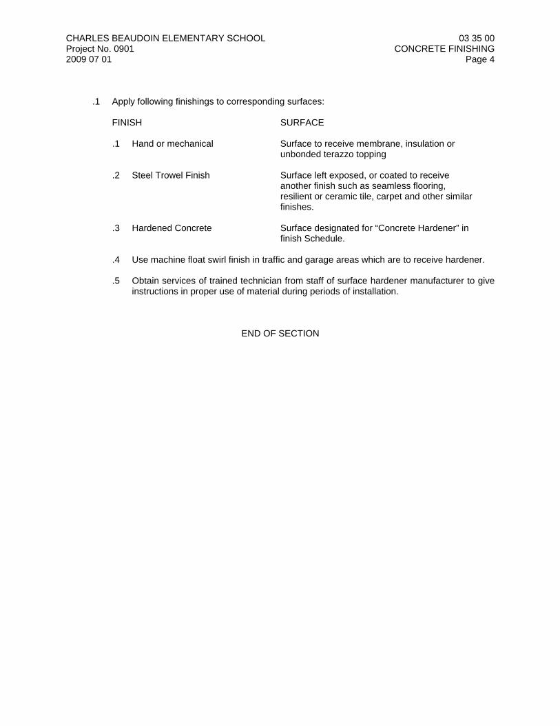
CHARLES BEAUDOIN ELEMENTARY SCHOOL 03 35 00 Project No. 0901 CONCRETE FINISHING 2009 07 01 Page 4 .1 Apply following finishings to corresponding surfaces: FINISH SURFACE
.1 Hand or mechanical Surface to receive membrane, insulation or unbonded terazzo topping
.2 Steel Trowel Finish Surface left exposed, or coated to receive another finish such as seamless flooring, resilient or ceramic tile, carpet and other similar finishes. .3 Hardened Concrete Surface designated for “Concrete Hardener” in finish Schedule. .4 Use machine float swirl finish in traffic and garage areas which are to receive hardener. .5 Obtain services of trained technician from staff of surface hardener manufacturer to give
instructions in proper use of material during periods of installation.
END OF SECTION
CHARLES BEAUDOIN ELEMENTARY SCHOOL 03 41 13 Project No. 0901 PRECAST CONCRETE HOLLOW CORE PLANKS 2009 07 01 Page 1 1 General 1.1 SECTION INCLUDES .1 Provide labour, material, equipment and services necessary for complete supply and
installation of:
.1 precast concrete slabs;
.2 precast stair landing slabs;
.3 grouting of panel joints, cores and openings;
.4 bearing pad, connection plates, brackets, anchors and hangers;
.5 preparation for concrete topping and floor finishes;
.6 preparation for mechanical and electrical trades;
.7 other work specified herein. .2 Provide items to other trades for building, with necessary instruction and supervision. .3 In addition to requirements specified above, provide other services whether or not specifically
required by Contract Documents, necessary for completion of work of this section. 1.2 RELATED SECTIONS .1 Section 03 30 00 – Cast-in-Place Concrete. .2 Section 03 41 23 – Precast Concrete Stairs. .3 Section 04 05 00 – Common Work Results for Masonry. .4 Other Sections related to Architectural components. 1.3 REFERENCES .1 Applicable standards governing work of this Section: - CSA A23.1-04 - CSA A23.2-04 - CSA A23.3-04 - CSA A23.4- 05 - CSA A251-00 - CSA W59-M1989 - CSA W186-M1990 1.4 QUALITY ASSURANCE .1 Qualification: .1 The precast concrete elements shall be fabricated and erected by manufacturing plant
certified by the Canadian Standards Association in the appropriate categories according to CSA Standard A251 “Qualification Code for Manufacturer of Architectural and Structural Precast Concrete”.
.2 The precast concrete manufacturer must be certified in accordance with CSA’s
certification procedures for precast concrete plants prior to submitting a bid. Only precast concrete elements fabricated in such certified plants shall be acceptable to the Owner and plant certification shall be maintained for the duration of the fabrication and erection.
.2 Quality Control:
CHARLES BEAUDOIN ELEMENTARY SCHOOL 03 41 13 Project No. 0901 PRECAST CONCRETE HOLLOW CORE PLANKS 2009 07 01 Page 2 .1 Provide Consultant with certified copies of quality control tests and inspection report
related to project. As specified in CSA3-A234 and CSA G279. 1.5 SUBMITTALS .1 Shop and Erection Drawings: .1 Submit shop and erection drawings in accordance with Section 01 33 00, indicating
among other items the following: .1 Location of each unit in complete structure; .2 Reinforcing steel detail and calculations; .3 Mix design and admixtures; .4 Connection and anchorage details; .5 Type of finish and location; .6 Lifting hooks and handling points; .7 Cambers; .8 Sequence of erection; .9 Special handling instructions or structural bracing requirements; .10 Drawings, details and calculations to be signed and sealed by license Professional
Engineer registered in the Province of Ontario who is responsible for structural analysis and design of the work on each shop drawing and support document.
.2 All shop drawings to be checked and initialled by Contractor before submission, and are
clearly shown dimension, size and location of all openings required by mechanical and electrical trades.
.3 Do not start fabrication until the design shop and erection drawings have been received. .4 Provide final record prints after all connections are made. .2 Certification: .1 Supplier to submit certification to the Consultant that all labour and materials provided are
in accordance with the Contract Documents. 1.6 DESIGN REQUIREMENTS .1 Live load deflection shall not exceed the span/360 or as indicated on the drawings. .2 The prestressed hollow core units shall meet the tested requirements for the restrained and
unrestrained two hours fire resistance rating. .3 Design shall limit maximum dead load camber of hollow core units to + 30mm. 1.7 PRODUCT DELIVERY, STORAGE AND HANDLING .1 Delivery of Material: Transport, handle and store units by approved methods to prevent
chipping and cracking. .2 Protect holes, reglets from water and ice during freezing weather. 2 Products 2.1 MATERIALS
CHARLES BEAUDOIN ELEMENTARY SCHOOL 03 41 13 Project No. 0901 PRECAST CONCRETE HOLLOW CORE PLANKS 2009 07 01 Page 3 .1 Precast Slabs: .1 Precast slabs shall be prestressed hollow core or solid concrete slabs 1220mm wide
manufactured by Coreslab Structures Inc. or Prestressed System Inc or approved equal. .2 Concrete as specified in Section 03300, except the minimum concrete compressive
strength to be 30 MPa at transfer, and 41MPa at 28 days. .3 Prestress Strand – Uncoated 7-wire cable conforming to CSA CAN3-A23.4. .2 Grout: 1:2½ cement-sand grout mix, 25MPa at 28 days minimum. .3 Connecting and Supporting Devices: Carbon steel plates, angles, items cast into concrete or
items connected to steel framing members, inserts; hot-dip galvanized. Do not paint surfaces in contact with concrete or surfaces required filed welding.
.4 Core Hole End Plugs: 50mm thick expanded polystyrene insulation plug at each cell end of
hollow core slab. 2.2 FABRICATION .1 Maintain plant records and quality control program during production of precast members.
Make records available upon request. .2 Ensure anchors, inserts, plates, angles, and other items are embedded at locations indicated
on shop drawings. .3 Provide required openings and embed accessories provided by other Sections, at indicated
locations. 3 Execution 3.1 ERECTION .1 Before commencing erection, examine work of other Sections on which the precast concrete
work will be supported. .2 Report immediately in writing to the Consultants all discrepancies in accuracy and suitability in
the location, bearing and retaining of structural members which will adversely affect the installation and permanency of the work of this Section.
.3 Commencement of the erection shall imply acceptance of the work of other Sections, upon
which the pre-cast concrete erection depends. .4 Precast slabs shall be installed in strict accordance with the manufacturer’s recommendations.
Provision shall be made for anchorage to means, wall, etc. to provide lateral support of such members.
.5 Install a tight, level position on true level bearing surface provided by others. Precast slabs
shall bear on 3mm masonite bearing pads or Fabreeka pads as required to distribute bearing stress. Minimum bearing 90mm on masonry and 75mm on structural steel.
.6 Level differential elevation of horizontal joints with grout to slope not more than 1:12, without
de-bonding or telegraphing through to floor finish. .7 All welding shall conform to CSA W59 for steel structures and CSA W186 for welding of
reinforcement except where specified otherwise.

CHARLES BEAUDOIN ELEMENTARY SCHOOL 03 41 13 Project No. 0901 PRECAST CONCRETE HOLLOW CORE PLANKS 2009 07 01 Page 4 .8 Those performing welding shall be certified by the Canadian Welding Bureau to the
requirements of CSA standard W47.1 and W186 for division 1 or division 2.1, as applicable to qualify to weld reinforcing bars to structural steel as indicated on the drawings.
.9 Clean field welds with wire brush and touch up with primer. .10 Co-operate with other trades to permit proper location of anchors, hangers, electrical outlets,
etc. 3.2 HOLES AND OPENINGS .1 Supply and install steel hangers for large openings which are indicated on the Drawings.
Erectors shall drill all through openings up to 150mm diameter requested by mechanical and electrical trades on site.
.2 Openings larger than 150mm must be located on reviewed shop drawings and could be cut in
field. Do not cut reinforcing without approval of precast slab manufacturer and Consultant. 3.3 GROUTING .1 Grout precast unit joints and all openings for anchorage and locations as indicated on
drawings so as to achieve a finished top and bottom surface. Tape seal underside of plank joints to prevent grout leakage.
3.4 FINISH .1 Top finish shall accept direct application of cementitious underlayment without de-bonding
including application of quarry tile, carpeting, parquet flooring, and resilient flooring material. .2 Where 38mm minimum concrete topping is to be applied. The top surface of the precast slab
is to be raked for bonding of topping. 3.5 FINISH FOR EXPOSED CEILINGS .1 Seal exposed ceiling longitudinal and wall joints with joint sealer as specified in Section 07 92
00. .2 In exposed areas, the underside of precast unit surface shall be finished as per CSA A23.4
“STANDARD FINISH”. 3.6 Provide touch-up coat on zinc rich paint after erection to connections, welds and anchors. 3.7 ERECTION TOLERANCES .1 Erect members level and plumb within allowable tolerances. .2 Design and erect to the following tolerances: .1 Maximum variation from plane or location indicated on drawings : 5mm in 3m and 9mm in 30m, non-cumulative. .2 Maximum offset from true alignment between member : 5mm. .3 Maximum differential camber variation between adjacent slabs shall be length/600 but
not greater than 30 mm.
CHARLES BEAUDOIN ELEMENTARY SCHOOL 03 41 13 Project No. 0901 PRECAST CONCRETE HOLLOW CORE PLANKS 2009 07 01 Page 5 .4 Maximum allowable step in exposed ceiling shall not exceed 5 mm. .5 Maximum variation from dimensions indicated on reviewed shop drawings : plus or minus 3mm. .6 Exposed joint dimension : 6mm. 3 When member cannot be adjusted to conform to design or tolerance criteria, cease work and advise Consultant. Execute modifications as directed. 3.7 CLEAN UP .1 Upon completion of the work of this Section, all surplus material and debris caused by the
work of this Trade shall be removed from the site.
END OF SECTION
CHARLES BEAUDOIN ELEMENTARY SCHOOLProject No.: 09012009 07 01
03 41 23PRECAST CONCRETE STAIRS
Page 1
1 General
1.1 SECTION INCLUDES
.1 Precast concrete stairs.
1.2 RELATED SECTIONS
.1 Section 03 41 13 - Precast Concrete Hollow Core Planks.
.2 Section 04 22 00 - Concrete Unit Masonry.
.3 Section 05 50 00 - Metal Fabrications: securement of metal railings and balustrades to precastconcrete stair treads.
.4 Section 07 92 00 - Joint Sealants: sealing butt joints of precast units at exposed underside offloor members.
.5 Section 09 30 00 - Tiling: stair landing, tread and riser coverings.
.6 Section 09 65 00 - Resilient Flooring: stair landing, tread and riser coverings.
1.3 REFERENCES
.1 ACI 318.1M: Metric Version of the Building Code Requirement for Structural Plain Concrete.
.2 ASTM A416/A416M-06: Standard Specification for Steel Strand, Uncoated Seven-Wire forPrestressed Concrete.
.3 CSA A23.4-05: Precast Concrete - Materials and Construction.
.4 CAN/CSA-A3001-03: Cementitious Materials for Use in Concrete.
.5 CAN/CSA-G30.18-M92 (R2002): Billet-Steel Bars for Concrete Reinforcement.
.6 Precast Concrete Institute (PCI): Manual on Design of Connections For Precast PrestressedConcrete.
.7 Precast Concrete Institute (PCI): Design Handbook - Precast and Prestressed Concrete.
1.4 DESIGN REQUIREMENTS
.1 Size components to withstand design loads in a restrained condition and to resist the live anddead design loads as indicated on the drawings.
.2 Maximum Allowable Deflection: 1/360 span.
.3 Design members exposed to the weather to provide for movement of components withoutdamage, failure of joint seals, undue stress on fasteners or other detrimental effects, whensubject to seasonal or cyclic day/night temperature ranges.
.4 Design system to accommodate construction tolerances, deflection of other building structuralmembers and clearances of intended openings.
.5 Calculate structural properties of framing members in accordance with ACI 318.1M.
1.5 SUBMITTALS
.1 Submit Shop Drawings and Product data as specified in Section 01 33 00.
.2 Shop Drawings: Indicate layout, unit locations, fabrication details, unit identification marks,reinforcement, connection details, support items, dimensions, openings, and relationship toadjacent materials. Indicate design loads, deflections, cambers, bearing requirements, andspecial conditions.

CHARLES BEAUDOIN ELEMENTARY SCHOOLProject No.: 09012009 07 01
03 41 23PRECAST CONCRETE STAIRS
Page 2
.3 Shop Drawings must be stamped, signed and dated by the fabricator's design engineer.
.4 Product Data: standard component configurations, design loads, deflections, cambers, andbearing requirements.
.5 Submit design data reports indicating calculations for loadings and stresses of fabricated,designed framing.
1.6 QUALITY ASSURANCE
.1 Fabricator's Design Engineer: a registered professional engineer, experienced in the design ofstructural precast concrete components, and licenced in the Place of the Work.
.2 Conform to requirements of PCI Manual on Design of Connections For Precast PrestressedConcrete, PCI Design Handbook - Precast and Prestressed Concrete, CSA A23.4, andACI 318.1M.
.3 Precast Fabricators and Erectors: Qualifying to CSA A23.4.
1.7 REGULATORY REQUIREMENTS
.1 Conform to CSA A23.4 and applicable building code for design load and constructionrequirements applicable to work of this Section.
1.8 DELIVERY, STORAGE AND HANDLING
.1 Refer to Section 01 60 00.
.2 Handle precast members in position consistent with their shape and design. Lift and supportonly from support points.
.3 Lifting or Handling Devices: Capable of supporting member in positions anticipated duringmanufacture, storage, transportation, and erection.
.4 Protect members to prevent staining, chipping, or spalling of concrete.
.5 Mark each member with date of production and final position in structure.
2 Products
2.1 MANUFACTURERS
.1 Manufacturers of precast concrete having Product considered acceptable for use:.1 PSI Prestressed Concrete Products..2 C. J. Pink Ltd..3 HY-Grade Precast Concrete.
.2 Substitutions: refer to Instructions to Bidders and Section 01 25 00.
2.2 MATERIALS
.1 Portland Cement: to CAN/CSA-A3001, Type GU; grey colour.
.2 Aggregate, Sand, Water, Admixtures: Determined by precast fabricator as appropriate todesign requirements.
.3 Tensioning Steel Tendons: to ASTM A416/A416M, Grade 250K or 270K, of sufficient strengthcommensurate with member design.
.4 Reinforcing Steel: to CAN/CSA-G30.18-M, deformed steel bars, of sufficient strengthcommensurate with member design.
CHARLES BEAUDOIN ELEMENTARY SCHOOLProject No.: 09012009 07 01
03 41 23PRECAST CONCRETE STAIRS
Page 3
2.3 ACCESSORIES
.1 Connecting and Supporting Devices: Carbon steel plates, angles, items cast into concrete oritems connected to steel framing members, inserts; prime painted hot-dip galvanized. Do notpaint surfaces in contact with concrete or surfaces requiring field welding.
.2 Grout: Non-shrink, Non-metallic, minimum yield strength of 70 MPa at 28 days.
.3 Bearing Pads: High density plastic, 3 mm thick, smooth both sides.
.4 Bolts, Nuts and Washers: High strength steel type recommended for structural steel joints.
.5 Prime Paint: Zinc rich alkyd type.
2.4 FABRICATION
.1 Maintain plant records and quality control program during production of precast members. Make records available upon request.
.2 Provide required openings with a dimension larger than 200 mm and embed accessoriesprovided by other Sections, at indicated locations.
2.5 FINISHES
.1 Finish members to smooth, architectural surface, without visible blemishes, fins, holes, orirregularities.
2.6 FABRICATION TOLERANCES
.1 Conform to CSA A23.4.
2.7 SOURCE QUALITY CONTROL
.1 Conduct testing and analysis of stressing tendons as specified in Section 01 40 00.
.2 Test samples to CSA A23.4.
3 Execution
3.1 PREPARATION
.1 Prepare support equipment for the erection procedure, temporary bracing, and induced loadsduring erection.
3.2 ERECTION
.1 Erect members without damage to structural capacity, shape, or finish. Replace or repairdamaged members.
.2 Provide temporary lateral support to prevent bowing, twisting, or warping of members.
.3 Level differential elevation of adjoining horizontal members with grout to maximum slope of1:12.
.4 Grout underside of bearing plates, and joints between members at floor locations.
.5 Secure units in place by welding.
3.3 ERECTION TOLERANCES
.1 Erect members level and plumb within allowable tolerances.
CHARLES BEAUDOIN ELEMENTARY SCHOOLProject No.: 09012009 07 01
03 41 23PRECAST CONCRETE STAIRS
Page 4
.2 Design and erect to the following tolerances:.1 Maximum Variation from Plane or Location Indicated on Drawings: 6 mm per 3 metres
and 9 mm in 30 mm, non-cumulative..2 Maximum Offset from True Alignment Between Members: 6 mm..3 Maximum Variation From Dimensions Indicated on Reviewed Shop Drawings: Plus or
minus 3 mm..4 Exposed Joint Dimension: 9 mm plus or minus 6 mm.
.3 When members cannot be adjusted to conform to design or tolerance criteria, cease work andadvise Consultant. Execute modifications as directed.
END OF SECTION
CHARLES BEAUDOIN ELEMENTARY SCHOOLProject No.: 09012009 07 01
04 05 00COMMON WORK RESULTS FOR MASONRY
Page 1
1 General
1.1 SECTION INCLUDES
.1 Procedures for masonry construction.
1.2 RELATED SECTIONS
.1 Section 04 05 10 - Masonry Mortaring and Grouting.
.2 Section 04 05 19 - Masonry Anchorage and Reinforcing.
.3 Section 04 05 23 - Masonry Accessories.
.4 Section 04 21 00 - Clay Unit Masonry.
.5 Section 04 22 00 - Concrete Unit Masonry.
.6 Section 04 22 26 - Decorative Concrete Unit Masonry.
.7 Section 05 12 00 - Structural Steel Framing: steel lintels and bearing plates.
.8 Section 05 50 00 - Metal Fabrications: fabricated metal items.
.9 Section 08 11 13 - Hollow Metal Frames.
.10 Section 08 44 13 - Glazed Aluminum Curtain Walls.
.11 Section 08 51 13 - Aluminum Windows.
1.3 REFERENCES
.1 CSA A371-04: Masonry Construction for Buildings.
.2 CSA S304.1-04: Masonry Design of Buildings (Limit States Design).
1.4 ENVIRONMENTAL REQUIREMENTS
.1 Conform to CSA A371.
.2 Provide heated enclosures and heat as necessary during cold weather construction.
.3 Protect freshly laid masonry from drying too rapidly during hot weather, by means ofwaterproof, non-staining coverings.
1.5 SUBMITTALS
.1 Submit masonry analysis and testing reports, prepared by an independent agency toConsultant, as specified in Section 01 40 00.
1.6 SAMPLES
.1 Submit samples as specified in Section 01 33 00.
.2 Samples: as follows:.1 Two samples of each type of masonry unit specified, illustrating colour, texture and
extremities of colour range;.2 One sample of each type of masonry reinforcement and tie specified in Section 04 05 19;.3 One sample of each type of masonry accessory specified in Section 04 05 23; and.4 as required for testing purposes.
CHARLES BEAUDOIN ELEMENTARY SCHOOLProject No.: 09012009 07 01
04 05 00COMMON WORK RESULTS FOR MASONRY
Page 2
1.7 QUALITY ASSURANCE
.1 Applicator: company specializing in commercial masonry work with a minimum of 5 yearsdocumented experience.
1.8 MOCK-UPS
.1 Construct mock-up as specified in Section 01 40 00.
.2 Mock-Up Panel: 1 200 x 1 800 mm size, illustrating veneer cladding types, textures andcolours; mortar joint thickness, tooled finish and colour. Include structural back-up materials,air and vapour barrier materials, through-wall flashing and weephole vents, wall insulation, wallties and connectors, and a partial window frame, illustrating the window head, jamb and sillconditions.
.3 Report mortar colour loading rate for acceptable panel.
.4 Remove mock-up panel from the Place of the Work upon Substantial Performance of theWork.
1.9 DELIVERY, STORAGE AND HANDLING
.1 Refer to Section 01 60 00.
.2 Deliver Products to the Place of the Work in dry condition.
.3 Keep Products dry until use.
.4 Store Products under waterproof cover on pallets or plank platforms held off ground by meansof plank or timber skids.
.5 Protect masonry units from damage.
2 Products
2.1 SOURCE QUALITY CONTROL
.1 Perform shop testing by independent inspection agency as specified in Section 01 40 00.
.2 Refer to individual specification Sections for Product-specific shop testing requirements.
3 Execution
3.1 QUALITY OF WORK
.1 Construct masonry plumb, level and true to line, with vertical joints in alignment.
.2 Lay out coursing and bond to achieve correct coursing heights, and continuity of bond aboveand below openings, with minimum of cutting.
.3 Maintain masonry courses to uniform width.
.4 Lay masonry in full bed of mortar, properly jointed with other work.
.5 Buttering corners of joints, and deep or excessive furrowing of mortar joints are not permitted.
.6 Maintain dry masonry beds and lay only dry masonry units. Do not pre-soak masonry units incold weather.
.7 Fully bond intersections, and external corners.
CHARLES BEAUDOIN ELEMENTARY SCHOOLProject No.: 09012009 07 01
04 05 00COMMON WORK RESULTS FOR MASONRY
Page 3
.8 Do not use chipped, cracked or otherwise damaged units in exposed and loadbearing masonrywalls.
.9 Build in items required to be built into masonry.
.10 Brace door frames to maintain plumb. Fill spaces between frame jambs and masonry withgrout.
.11 Prevent displacement of built-in items during construction. Check plumb, location andalignment frequently, as work progresses.
.12 Place grout as required to maintain an adequate level of structural bearing surface with novoids and to a depth as indicated on Drawings.
.13 Prevent ingress of mortar and grout in cores of acoustical masonry units.
3.2 JOINTING
.1 Make vertical and horizontal joints equal and of uniform thickness.
.2 Tooled Joints: Allow joints to set just enough to remove excess water, then tool joints withround jointer to result in smooth, compressed, uniformly concave joints.
.3 Flush Joints: Strike flush joints that will be concealed within the wall or which will receive acoating of plaster, tile, insulation, resoilient base, bituminous foundation protection, or otherjoint-concealing finish. Do not strike flush mortar joints designated to receive painted or otherthin finishes.
3.3 CUTTING
.1 Cut out masonry neatly for recessed or built-in objects.
.2 Make cuts straight, clean and free from uneven edges.
.3 Make Good masonry which has cracked or broken as a result of cutting in built-in objects.
3.4 PARGING
.1 Use parging mortar as specified in Section 04 22 00.
.2 Apply parging in 2 coats not less than 10 mm thick.
.3 Roughen first coat to ensure a good bond for second coat. Allow first coat to dry a minimum of24 hours before applying second coat.
.4 Dampen first coat with water before applying second coat.
3.5 SUPPORT OF LOADS
.1 Use 20 MPa strength grout as specified in Section 04 05 10, where grout fill is used instead ofsolid masonry units.
.2 Install building paper below voids to be filled with grout. Keep paper 25 mm back from faces ofunits.
3.6 PROVISIONS FOR MOVEMENT
.1 Leave a 10 mm deflection space below shelf angles.
.2 Leave a 10 mm space between masonry and vertical structural elements.
.3 Leave a 25 mm space between top of non-loadbearing walls and partitions and structuralelements. Fill space with compressible material and seal both sides as specified in Section07 92 00. Do not use wedges.
CHARLES BEAUDOIN ELEMENTARY SCHOOLProject No.: 09012009 07 01
04 05 00COMMON WORK RESULTS FOR MASONRY
Page 4
.4 Provide continuous movement control joints, properly sealed with backing rod and jointsealant, interior and exterior surfaces of wall system to ensure water tightness; where indicatedon Drawings, and as follows: .1 at all column locations, and.2 spaced along continuous lengths of wall, maximum 6.0 metres OC.
3.7 LOOSE STEEL LINTELS
.1 Install loose steel lintels. Centre lintel over opening width.
.2 Bridge openings less than 450 mm wide with 6 mm thick mild steel plate lintels, bearingminimum 100 mm on each side of opening and set on dry pack grout. Width of plate to beequal to the wall thickness less 15 mm.
3.8 TEMPORARY WALL BRACING
.1 Provide engineered temporary bracing for masonry walls to resist wind pressure and otherlateral loads during and after erection until permanent lateral support is in place.
3.9 PROTECTING MASONRY
.1 Refer to Section 01 76 00.
.2 Keep masonry dry using waterproof, non-staining coverings that extend over walls and downsides sufficient to protect walls from wind-driven rain, until masonry is completed and protectedby flashings or other permanent construction.
.3 Protect masonry and other work from marking and other damage.
.4 Protect completed work from mortar droppings. Use non-staining coverings.
3.10 FIELD QUALITY CONTROL
.1 Field Inspection: Consultant will inspect installed masonry and reject masonry that is chipped,cracked, or blemished (streaked, stained or otherwise damaged), as described below.
.2 Masonry will be inspected to be free of chips, cracks or other blemishes on the finished face orfront edges of the masonry units exceeding 10 mm or that can be seen from a distance of3.0 metres. Masonry units supplied with a rusticated face will be inspected for cracks andblemishes only.
.3 Make Good rejected masonry as directed by Consultant.
3.11 TOLERANCES
.1 Conform to CSA A371.
3.12 CLEANING
.1 Clean masonry as work progresses.
.2 Allow mortar droppings on masonry to partially dry then remove by means of brushing with astiff fibre brush.
.3 Post-Construction: Clean one-half of mock-up panel as directed below and leave for oneweek. If no harmful effects appear and after mortar has set and cured, clean masonry asfollows:.1 Protect windows, sills, doors, trim and other work from damage..2 Remove large particles with stiff fiber brushes wood paddles without damaging surface.
Saturate masonry with clean water and flush off loose mortar and dirt.
CHARLES BEAUDOIN ELEMENTARY SCHOOLProject No.: 09012009 07 01
04 05 00COMMON WORK RESULTS FOR MASONRY
Page 5
.3 Scrub with solution of 25 mL trisodium phosphate and 25 mL household detergentdissolved in 1 L of clean water using stiff fibre brushes, then clean off immediately withclean water using hose.
.4 Repeat cleaning process as often as necessary to remove mortar and other stains.
.4 Use alternative cleaning solutions and methods for difficult to clean masonry only afterconsultation with masonry unit manufacturer.
END OF SECTION
CHARLES BEAUDOIN ELEMENTARY SCHOOLProject No.: 09012009 07 01
04 05 10MASONRY MORTARING AND GROUTING
Page 1
1 General
1.1 SECTION INCLUDES
.1 Mortar and grout for unit masonry.
1.2 PRODUCTS FURNISHED OR INSTALLED UNDER OTHER SECTIONS
.1 Section 05 12 00 includes non-shrinking grout for structural steel.
1.3 RELATED SECTIONS
.1 Section 04 05 00 - Common Work Results for Masonry.
.2 Section 04 21 00 - Clay Unit Masonry.
.3 Section 04 22 00 - Concrete Unit Masonry.
.4 Section 04 22 26 - Decorative Concrete Unit Masonry.
1.4 REFERENCES
.1 ASTM C207-06: Standard Specification for Hydrated Lime for Masonry Purposes.
.2 CSA A179-04: Mortar and Grout for Unit Masonry.
.3 CSA S304.1-04: Masonry Design for Buildings (Limit States Design).
.4 CAN/CSA-A3001-03: Cementitious Materials for Use in Concrete.
.5 CAN/CSA-A3002-03: Masonry and Mortar Cement.
1.5 RESPONSIBILITY
.1 Make Good work that includes mortar not meeting the required specification. This includes theremoval of the affected walls and the reconstruction of such walls using new materials.
1.6 PRODUCT DATA
.1 Submit Product data as specified in Section 01 33 00.
.2 Product Data: on design mix, indicating Proportion or Property specification method used,required environmental conditions and admixture limitations.
1.7 SAMPLES
.1 Submit samples as specified in Section 01 33 00.
.2 Verification Samples: 2 ribbons of mortar, illustrating colour and colour range..1 Complete upon acceptance, confirmation of site-mixed colour additive proportional to mix
batch site..2 Prepare and submit sample colour ribbons for each days work for review of consistency.
1.8 DELIVERY, STORAGE AND HANDLING
.1 Refer to Section 01 60 00.
.2 Deliver Products in original unbroken and undamaged packages with the maker's name andbrand distinctly marked thereon, and upon delivery store in a shed until used on the work.
.3 Store or pile sand on a plank platform and protect from dirt and rubbish. Store mortar materialsand sand in such a manner as to prevent deterioration or contamination by foreign materials.
CHARLES BEAUDOIN ELEMENTARY SCHOOLProject No.: 09012009 07 01
04 05 10MASONRY MORTARING AND GROUTING
Page 2
1.9 PROJECT CONDITIONS
.1 Maintain materials and surrounding air temperature to minimum 5 degrees Celsius andmaximum 50 degrees Celsius prior to, during, and 48 hours after completion of masonry work.
.2 Do not use anti-freeze, liquid salts, or other substances to lower the freezing point of mortar orgrout. Conform to CSA A179.
2 Products
2.1 MANUFACTURERS
.1 Manufacturers of masonry cement having Product considered acceptable for use:.1 St. Lawrence Cement..2 Lafarge Construction Materials.
.2 Manufacturers of hydrated lime having Product considered acceptable for use:.1 Genlime Group L.P..2 Rockwell Lime Company.
.3 Manufacturers of dry, combined materials for mortar having Product considered acceptable foruse:.1 Daubois..2 Jiffy Mortar Systems..3 Genlime Group L.P.
.4 Manufacturers of mortar pigment having Product considered acceptable for use:.1 Bayer Pigments..2 Elementis Pigments..3 Hamburger Company.
.5 Substitutions: refer to Instructions to Bidders and Section 01 25 00.
2.2 MATERIALS
.1 Portland Cement: to CAN/CSA-A3001, Type GU; Grey colour.
.2 Masonry Cement: to CAN/CSA-A3002, Type N.
.3 Hydrated Lime: to ASTM C207, Type S-Special.
.4 Mortar Aggregate: natural sand, to CSA A179, standard masonry type; clean, dry, protectedagainst dampness, freezing, and foreign matter.
.5 Grout Aggregate: to CSA A179, as follows:.1 Coarse: maximum 10 mm size; 27 percent by volume..2 Fine: clean well graded sharp sand; 54 percent by volume.
.6 Water: potable, clean and free of deleterious amounts of acids, alkalies or organic materials.
2.3 ADMIXTURES
.1 Plasticizer: water reducing type, reducing porosity and absorption to increase bond strength.
.2 Water Repellent: mixture of calcium carbonate and hydrous magnesium aluminum silicatepowders; eg. Hydrocide Powder by Degussa Building Systems.
.3 Colour: liquid manufactured or natural oxide pigment, colour and loading as selected byConsultant.
CHARLES BEAUDOIN ELEMENTARY SCHOOLProject No.: 09012009 07 01
04 05 10MASONRY MORTARING AND GROUTING
Page 3
2.4 MORTAR MIXES
.1 Mortar for Use with Loadbearing Concrete Unit Masonry: to CSA A179, Type 'S' using theProportion specification method; portland cement-masonry cement mix; c/w water repellentadmixture.
.2 Mortar for Use with Non-loadbearing Concrete Unit Masonry: to CSA A179, Type 'N' using theProportion specification method; masonry cement mix; c/w water repellent admixture.
.3 Mortar for Use with Clay Unit Masonry and Decorative Concrete Unit Masonry: to CSA A179,Type 'N' using the Proportion specification method; portland cement-hydrated lime-sand mix;comprised of 1-part hydrated lime, 1-part Portland cement, 6-parts mortar aggregate; c/wintegral colour as selected by Consultant; minimum 3 colours required.
2.5 MORTAR MIXING
.1 Thoroughly mix mortar ingredients in proper quantities needed for immediate use toCSA A179.
.2 Add mortar colour and admixtures to requirements of manufacturer's instructions.
.3 Provide uniformity of mix and colouration.
.4 Take representative samples for testing consistency of strength and colour to CSA A179.
.5 Use mortar within 2 hours after mixing at temperatures of 26 degrees Celsius, or 2-1/2 hours attemperatures under 10 degrees Celsius.
2.6 GROUT MIXES
.1 Reinforced Cores, Bond Beams and Lintels: 20 MPa strength at 28 days; 200 - 250 mm slump;mixed to requirements of CSA A179, Fine Grout.
2.7 GROUT MIXING
.1 Thoroughly mix mortar ingredients accurately in measured quantities needed for immediateuse.
3 Execution
3.1 EXAMINATION
.1 Refer to Section 01 71 00.
.2 Request Consultant inspection of spaces to be grouted.
3.2 PREPARATION
.1 Apply bonding agent to existing concrete surfaces.
.2 Plug clean-out holes with masonry units to prevent leakage of grout materials.
.3 Brace masonry for wet grout pressure.
.4 Remove excess mortar from grout spaces.
3.3 APPLICATION
.1 Install mortar and grout as specified in Sections 04 21 00, 04 22 00 and 04 22 26.
.2 Work grout into masonry cores and cavities to eliminate voids.
.3 Do not displace reinforcement while placing grout.
CHARLES BEAUDOIN ELEMENTARY SCHOOLProject No.: 09012009 07 01
04 05 10MASONRY MORTARING AND GROUTING
Page 4
3.4 FIELD QUALITY CONTROL
.1 Perform inspection and testing of mortar and grout mixes as specified in Section 01 40 00.
.2 Submit sample cubes for laboratory testing and test data as specified in Section 01 40 00 andto CSA S304.1.
.3 Report on the compressive strength and water content of mortar and grout mixes.
END OF SECTION
CHARLES BEAUDOIN ELEMENTARY SCHOOLProject No.: 09012009 07 01
04 05 19MASONRY ANCHORAGE AND REINFORCING
Page 1
1 General
1.1 SECTION INCLUDES
.1 Reinforcement, ties and anchors for use with unit masonry.
1.2 RELATED SECTIONS
.1 Section 04 05 00 - Common Work Results for Masonry.
.2 Section 04 05 10 - Masonry Mortaring and Grouting.
.3 Section 04 05 23 - Masonry Accessories.
.4 Section 04 21 00 - Clay Unit Masonry.
.5 Section 04 22 00 - Concrete Unit Masonry.
.6 Section 04 22 26 - Decorative Concrete Unit Masonry.
.7 Section 05 12 00 - Structural Steel Framing: steel lintels and bearing plates.
.8 Section 05 50 00 - Metal Fabrications: fabricated metal items.
1.3 REFERENCES
.1 ASTM A82/A82M-07: Standard Specification for Steel Wire, Plain, For ConcreteReinforcement.
.2 ASTM A123/A123M-02: Standard Specification for Zinc (Hot-Dip Galvanized) Coatings on Ironand Steel Products.
.3 ASTM A153/A153M-01a: Standard Specification for Zinc Coating (Hot-Dip) on Iron and SteelHardware.
.4 ASTM A167-99 (2004): Standard Specification for Stainless and Heat-ResistingChromium-Nickel Steel Plate, Sheet, and Strip.
.5 ASTM A580/A580M-06: Standard Specification for Stainless Steel Wire.
.6 ASTM A641/A641M-98: Standard Specification for Zinc-Coated (Galvanized) Carbon SteelWire.
.7 ASTM A1011/A1011M-07: Standard Specification for Steel, Sheet and Strip, Hot-Rolled,Carbon, Structural, High-Strength Low-Alloy, High-Strength Low-Alloy with ImprovedFormability and Ultra-High Strength.
.8 CAN/CGSB-1.40-M89: Primer, Structural Steel, Oil Alkyd Type.
.9 CSA A370-04: Connectors for Masonry.
.10 CSA A371-04: Masonry Construction for Buildings.
.11 CSA G30.18-M92 (R2002): Billet-Steel Bars for Concrete Reinforcement.
.12 CSA S304.1-04: Masonry Design for Buildings (Limit States Design).
1.4 QUALITY ASSURANCE
.1 Single-Source Responsibility: Provide each type of Product from a single manufacturer.
1.5 MOCK-UPS
.1 Supply Product for construction of mock-up panel as specified in Section 04 05 00.
CHARLES BEAUDOIN ELEMENTARY SCHOOLProject No.: 09012009 07 01
04 05 19MASONRY ANCHORAGE AND REINFORCING
Page 2
2 Products
2.1 MANUFACTURERS
.1 Manufacturers of horizontal joint reinforcement and anchors having Product consideredacceptable for use:.1 Blok-Lok..2 Dur-O-Wal.
.2 Manufacturers of masonry veneer ties having Product considered acceptable for use:.1 Blok-Lok..2 Fero.
.3 Substitutions: refer to Instructions to Bidders and Section 01 25 00.
2.2 MATERIALS
.1 Exterior Wall, Single-Wythe Horizontal Joint Reinforcement: Truss type, 4.8 mm side rods with4.8 mm cross ties; to ASTM A82/A82M; hot-dipped galvanized; eg. Dur-O- Wal DA3100.
.2 Interior Wall, Single-Wythe Horizontal Joint Reinforcement: Ladder type, 3.7 mm side rodswith 3.7 mm cross ties; to ASTM A82/A82M; regular mill galvanized; eg. Dur-O- Wal DA3200.
.3 Masonry Veneer Wall Tie (CMU Back-up): adjustable, dual component slotted design; eg. FeroSlotted BlockTie (Type I), comprised of:.1 Slotted Block Plate: 1.61 mm thick stainless steel plate, to ASTM A167, Type 304; length
to suit air space and CMU width dimension, less 6 mm..2 V-Tie: 4.76 mm diameter stainless steel wire, to ASTM A580, Type 304; length to provide
placement of tie legs at centerline of veneer..3 Insulation Retaining Clip: purpose-made plastic, as recommended by tie manufacturer.
.4 Masonry Veneer Wall Tie (Concrete Back-up): adjustable, dual component slotted design; eg.Fero Slotted Rap-Tie, comprised of:.1 Slotted L-Plate: 1.61 mm thick stainless steel plate, to ASTM A167, Type 304; length to
suit air space dimension..2 V-Tie: 4.76 mm diameter stainless steel wire, to ASTM A580, Type 304; length to provide
placement of tie legs at centerline of veneer..3 Fastener: 6 mm OD Tapcon screws; minimum 2 screws per tie..4 Insulation Retaining Clip: purpose-made plastic, as recommended by tie manufacturer.
.5 Reinforcing Steel: to CSA G30.18, as specified in Section 03 20 00; sizes as indicated onDrawings.
.6 Strap Anchors: 4.76 mm thick steel plate, hot dipped galvanized; U-shaped and Z-shaped tosuit application; eg. BLT11 by Blok-Lok.
.7 Fasteners: purpose made for substrate; stainless steel finish for exterior walls, mill galvanizedfor interior walls, to CSA A370.
2.3 SHOP FINISHING
.1 Mill Galvanizing: to ASTM A641, Regular; minimum 30 g/m2 zinc coating.
.2 Hot Dip Galvanizing:.1 Horizontal Joint Reinforcement Wire: to ASTM A153/A153M, Class B2, minimum
458 g/m2 zinc coating..2 Strap Anchors: to ASTM A123/A123M, minimum 503 g/m2 zinc coating.
CHARLES BEAUDOIN ELEMENTARY SCHOOLProject No.: 09012009 07 01
04 05 19MASONRY ANCHORAGE AND REINFORCING
Page 3
3 Execution
3.1 PREPARATION
.1 Supply metal anchors to the appropriate trades for placement. Direct correct placement.
.2 Verify that anchorages embedded in concrete or attached to structural steel members areproperly placed. Embed anchorages in every second joint.
3.2 INSTALLATION
.1 Install masonry connectors and reinforcement to CSA A370.
.2 Place horizontal joint reinforcement continuous in every second horizontal joint.
.3 Place horizontal joint reinforcement in first and second horizontal joints above and belowopenings. Extend 400 mm minimum each side of opening.
.4 Place horizontal joint reinforcement continuous in first and second joints below top of walls.
.5 Reinforce joint corners and intersections with strap anchors spaced at 400 mm OC vertically.
.6 Place reinforcing bars supported and secured against displacement. Maintain minimumclearance of 12 mm from masonry and not less than one bar diameter between bars..1 Provide 2-15M reinforcing bars grouted vertically into CMU cores both sides of masonry
openings.
.7 Provide clean out openings at the bottom of cores containing vertical reinforcement at each liftor pour.
.8 Solidly fill block cores containing vertical reinforcement or anchor bolts with grout.
.9 Secure wall ties to structural back-up for veneer at maximum 400 mm OC vertically and600 mm OC horizontally.
.10 Double quantity of wall ties within 200 mm of openings.
END OF SECTION
CHARLES BEAUDOIN ELEMENTARY SCHOOLProject No.: 09012009 07 01
04 05 23MASONRY ACCESSORIES
Page 1
1 General
1.1 SECTION INCLUDES
.1 Masonry flashing and accessories.
1.2 RELATED SECTIONS
.1 Section 04 05 00 - Common Work Results for Masonry.
.2 Section 04 05 10 - Masonry Mortaring and Grouting.
.3 Section 04 05 19 - Masonry Anchorage and Reinforcing.
.4 Section 04 21 00 - Clay Unit Masonry.
.5 Section 04 22 00 - Concrete Unit Masonry.
.6 Section 04 22 26 - Decorative Concrete Unit Masonry.
.7 Section 05 12 00 - Structural Steel Framing: steel lintels and bearing plates.
.8 Section 05 50 00 - Metal Fabrications: fabricated metal items.
.9 Section 07 21 00 - Thermal Insulation.
.10 Section 07 26 00 - Self-Adhered Membrane Air and Vapour Retarders: air barrier as an integralpart of the cavity wall system.
.11 Section 07 62 16 - Sheet Metal Flashing and Trim.
.12 Section 07 92 00 - Joint Sealants: rod and sealant at control and expansion joints.
1.3 REFERENCES
.1 ASTM A153/A153M-01a: Standard Specification for Zinc Coating (Hot-Dip) on Iron and SteelHardware.
.2 ASTM A167-99 (2004): Standard Specification for Stainless and Heat-ResistingChromium-Nickel Steel Plate, Sheet, and Strip.
.3 ASTM A653/A653M-07: Standard Specification for Steel Sheet, Zinc Coated (Galvanized) orZinc-Iron Alloy-Coated (Galvannealed) by the Hot-Dip Process.
.4 CSA A371-04: Masonry Construction for Buildings.
1.4 MOCK-UPS
.1 Supply Product for construction of mock-up as specified in Section 04 05 00.
2 Products
2.1 MANUFACTURERS
.1 Manufacturers of mortar dropping control devices and cell vents having Products consideredacceptable for use:.1 Masonry Technology Inc.
.2 Substitutions: refer to Instructions to Bidders and Section 01 25 00.
CHARLES BEAUDOIN ELEMENTARY SCHOOLProject No.: 09012009 07 01
04 05 23MASONRY ACCESSORIES
Page 2
2.2 MATERIALS
.1 Flexible Flashing: 1.0 mm thick self-adhering SBS rubberized asphalt membrane with a cross-laminated HPDE top surface, sheet width to suit application; eg. Blueskin TWF by Bakor.
.2 Sheet Metal Flashing: 0.61 mm thick steel; flat sheet stock to ASTM A653/A653M, Grade 230,hot dipped galvanized.
.3 Cavity Firestops: minimum 1.2 mm thick stainless steel sheet, to ASTM A167, Type 304.
.4 Movement Joint Filler: closed cell polyurethane or polyethylene oversized by 50 percent;self-expanding.
.5 Building Paper: No. 15 asphalt saturated felt.
.6 Mortar Dropping Control Device: 0.6 mm thick high impact polystyrene sheets. They areformed with corrugations and a spunbond polypropylene fabric on one side with a 102 mm skirton one edge; Sure Cavity SC5016 by Masonry Technology Inc.
.7 Cavity Vent, Type CV-1: 57 mm wide weep legs spaced at 241 mm OC, 25 mm widecontinuous belt; 152 mm total width; CV5010 by Masonry Technology Inc.
.8 Cavity Vent, Type CV-2: 0.6 mm thick acetac, 9.5 mm wide, 9.5 mm high, 114.3 mm long;HJW 3845 by Masonry Technology Inc.
.9 Cavity Wall Filler: compressible closed cell foam.
.10 Nailing Inserts: 0.6 mm thick purpose made galvanized steel inserts for setting in mortar joints.
.11 Primer: as recommended by sheet membrane manufacturer.
2.3 SHOP FINISHES
.1 Galvanizing: to ASTM A153/A153M, Class B2.
.2 Prefinished Coating: baked ceramic pigmentation coating, applied to a minimum 0.025 mm dryfilm thickness and having a specular gloss of 30 (plus or minus 5) gloss units when measuredwith a Gardner 60 degree gloss meter; eg. Colorite HMP by Valspar, colour as selected byConsultant from manufacturer's extended colour range.
3 Execution
3.1 PREPARATION
.1 Apply primer to porous surfaces scheduled to receive self-adhering sheet membranes.
3.2 INSTALLATION
.1 Provide vertical cavity wall fillers at external corners to prevent wind driven moisture fromcrossing the cavity. Bond filler to outer wythe using approved adhesive.
.2 Provide nailing inserts in mortar joints at 400 mm OC each way, for attachment of wallstrapping.
.3 Provide vertical cavity firestops at a maximum spacing of 9.0 metres OC.
.4 Provide horizontal cavity firestops at every floor slab.
.5 Provide mortar dropping control devices at the base of wall cavities, in accordance withmanufacturer's installation guidelines.
CHARLES BEAUDOIN ELEMENTARY SCHOOLProject No.: 09012009 07 01
04 05 23MASONRY ACCESSORIES
Page 3
.6 Provide Cavity Vent Type CV-1 immediately over flashings at brick ledges and top-of-foundation walls, spaced at maximum 800 mm OC.
.7 Provide Cavity Vent Type CV-2 immediately over flashings at wall opening heads, in headjoints spaced at maximum 800 mm OC.
.8 Provide Cavity Vent Type CV-2 along the top of wall cavities, in head joints spaced atmaximum 800 mm OC.
3.3 FLASHING
.1 Provide flashings in masonry to CSA A371.
.2 Install flashings under exterior masonry walls bearing on foundation walls or slabs; shelfangles, and steel lintel angles at wall openings, and as indicated on Drawings.
.3 In double wythe walls and veneered walls, carry flashings from front edge of masonry, underouter wythes, then up backing not less than 150 mm, and as follows:.1 Masonry Backing: embed flashing 25 mm in joint..2 Concrete Backing: insert flashing into reglets and seal joint..3 Sheathed Backing: secure flashing to sheathing behind air barrier.
.4 Lap joints 150 mm and seal watertight.
.5 Provide end dam flashing at both jambs of openings, to prevent water from travellinghorizontally past the flashing ends.
.6 Return horizontal base flashing a minimum of 100 mm around corner to overlap abuttingflashing. Seal watertight.
3.4 MOVEMENT JOINTS
.1 Provide vertical and horizontal movement control joints in accordance with the BIA TechnicalNote on Brick Construction 18A - Accommodating Expansion of Brickwork.
.2 Do not continue horizontal joint reinforcing across movement control joints.
.3 Construct movement joints as follows:.1 Concrete Masonry Units: Form movement control joint by use of sheet building paper
bond breaker one side fitted to hollow contour of block unit end. Fill created core withgrout fill. Rake joint at exposed faces for rod and sealant.
.2 Clay Brick and Calcium Silicate Manufactured Stone Masonry: leave head joints betweenstacked units void of mortar and other firm obstructions, ready for application of bondbreaker and joint sealant.
.4 Size joint for sealant performance as specified in Section 07 92 00.
3.5 PROTECTION
.1 Protect flashings from mortar droppings.
END OF SECTION
CHARLES BEAUDOIN ELEMENTARY SCHOOLProject No.: 09012009 07 01
04 21 00CLAY UNIT MASONRY
Page 1
1 General
1.1 SECTION INCLUDES
.1 Clay brick masonry veneer.
1.2 RELATED SECTIONS
.1 Section 04 05 00 - Common Work Results for Masonry.
.2 Section 04 05 10 - Masonry Mortaring and Grouting.
.3 Section 04 05 19 - Masonry Anchorage and Reinforcing: wall ties.
.4 Section 04 05 23 - Masonry Accessories: flashing, weep vents, mortar dropping controldevices, movement joint fillers.
.5 Section 04 22 00 - Concrete Unit Masonry.
.6 Section 04 22 26 - Decorative Concrete Unit Masonry.
.7 Section 05 12 00 - Structural Steel Framing: steel lintels and bearing plates.
.8 Section 05 50 00 - Metal Fabrications: fabricated metal items.
.9 Section 07 21 00 - Thermal Insulation: cavity wall insulation.
.10 Section 07 26 00 - Self-Adhered Membrane Air and Vapour Retarders: air/vapour barrier as anintegral part of the cavity wall system.
.11 Section 07 62 16 - Sheet Metal Flashing and Trim.
.12 Section 07 92 00 - Joint Sealants: rod and sealant at control and expansion joints.
.13 Section 08 11 13 - Hollow Metal Frames.
.14 Section 08 41 13 - Aluminum Entrances and Storefronts.
.15 Section 08 44 13 - Glazed Aluminum Curtain Wall.
.16 Section 08 51 13 - Aluminum Windows.
1.3 REFERENCES
.1 CAN/CSA-A82.1-M87 (R2003): Burned Clay Brick (Solid Masonry Units Made from Clay orShale).
.2 CSA A371-04: Masonry Construction for Buildings.
.3 CSA S304.1-04: Masonry Design for Buildings (Limit States Design).
1.4 MOCK-UPS
.1 Supply Product for construction of mock-up panel as specified in Section 04 05 00.
1.5 PROJECT CONDITIONS
.1 Environmental Requirements: as specified in Section 04050.
1.6 DELIVERY, STORAGE AND HANDLING
.1 Refer to Section 04 05 00.
CHARLES BEAUDOIN ELEMENTARY SCHOOLProject No.: 09012009 07 01
04 21 00CLAY UNIT MASONRY
Page 2
2 Products
2.1 MATERIALS
.1 Face Brick: burned clay brick, to CAN/CSA A82.1-M, Type FBS, Grade SW; sizes to matchexisting, colours as noted on Drawings.
.2 Veneer Mortar: as specified in Section 04 05 10.
.3 Reinforcement and Anchorages: as specified in Section 04 05 19.
.4 Accessories: flashings, movement joint filler, mortar dropping control device, cavity vents,nailing inserts and cavity wall filler as specified in Section 04 05 23.
.5 Cavity Wall Insulation: extruded polystyrene rigid board, as specified in Section 07 21 00.
2.2 SOURCE QUALITY CONTROL
.1 Perform shop inspection and testing of unit masonry as specified in Section 01 40 00.
.2 Submit samples for laboratory testing and test data as specified in Section 01 40 00 and toCSA S304.1.
.3 Test brick to CAN3-A82.2-M78 (R2003).
3 Execution
3.1 INSTALLATION
.1 Place masonry veneer to lines and levels indicated, as specified in Section 04 05 00.
.2 Lay brick in running bond, unless indicated otherwise on Drawings.
.3 Cut brick to accommodate brick patterns.
.4 Maintain 10 mm wide mortar joints in both directions.
.5 Install cavity wall insulation over air/vapour barrier as specified in Section 07 21 00. Securewith approved fasteners.
.6 Install masonry accessories as specified in Section 04 05 23.
.7 Secure wall ties to structural back-up for veneer as specified in Section 04 05 19.
.8 Install masonry flashing as specified in Section 04 05 23.
.9 Install loose steel lintels as scheduled and as specified in Section 04 05 00.
.10 Provide vertical and horizontal movement control joints as specified in Section 04 05 23 and asindicated on Drawings.
3.2 TOLERANCES
.1 Variation from Unit to Adjacent Unit: 1.5 mm maximum.
.2 Variation of Joint Thickness: 3 mm per metre maximum.
3.3 FIELD QUALITY CONTROL
.1 Consultant will inspect installed masonry and reject masonry that is chipped, cracked, orblemished (streaked, stained or otherwise damaged), as described below.
CHARLES BEAUDOIN ELEMENTARY SCHOOLProject No.: 09012009 07 01
04 21 00CLAY UNIT MASONRY
Page 3
.2 Masonry will be inspected to be free of chips, cracks or other blemishes on the finished face orfront edges of the masonry units exceeding 10 mm or that can be seen from a distance of3.0 metres. Masonry units supplied with a rusticated face will be inspected for cracks andblemishes only.
.3 Make Good rejected masonry as directed by Consultant.
3.4 CLEANING
.1 Clean masonry as specified in Section 04 05 00.
3.5 PROTECTION
.1 Protect clay brick from damage resulting from subsequent construction operations. Refer toSection 04 05 00.
.2 Remove protection materials upon Substantial Performance of the Work, or when risk ofdamage is no longer present.
END OF SECTION
CHARLES BEAUDOIN ELEMENTARY SCHOOLProject No.: 09012009 07 01
04 22 00CONCRETE UNIT MASONRY
Page 1
1 General
1.1 SECTION INCLUDES
.1 Concrete unit masonry.
1.2 RELATED SECTIONS
.1 Section 04 05 00 - Common Work Results for Masonry.
.2 Section 04 05 10 - Masonry Mortaring and Grouting.
.3 Section 04 05 19 - Masonry Anchorage and Reinforcing.
.4 Section 04 05 23 - Masonry Accessories.
.5 Section 04 21 00 - Clay Unit Masonry.
.6 Section 04 22 26 - Decorative Concrete Unit Masonry.
.7 Section 05 12 00 - Structural Steel Framing: steel lintels, and bearing plates.
.8 Section 05 50 00 - Metal Fabrications: fabricated metal items to be embedded in foundationwalls.
.9 Section 07 21 00 - Thermal Insulation: cavity wall insulation.
.10 Section 07 62 16 - Sheet Metal flashing and Trim.
.11 Section 07 92 00 - Joint Sealants: rod and sealant at control and expansion joints.
.12 Section 08 11 13 - Hollow Metal Frames.
.13 Section 08 44 13 - Glazed Aluminum Curtain Wall.
.14 Section 08 51 13 - Aluminum Windows.
1.3 REFERENCES
.1 ASTM C331-05: Standard Specification for Lightweight Aggregates for Concrete MasonryUnits.
.2 CSA A165 Series-04: CSA Standards on Concrete Masonry Units.
.3 CSA A371-04: Masonry Construction for Buildings.
.4 CSA S304.1-04: Masonry Design for Buildings (Limit States Design).
1.4 MOCK-UPS
.1 Supply Product for construction of mock-up panel as specified in Section 04 05 00.
1.5 PROJECT CONDITIONS
.1 Environmental Requirements: as specified in Section 04 05 00.
1.6 DELIVERY, STORAGE AND HANDLING
.1 Refer to Section 04 05 00.
CHARLES BEAUDOIN ELEMENTARY SCHOOLProject No.: 09012009 07 01
04 22 00CONCRETE UNIT MASONRY
Page 2
2 Products
2.1 MASONRY UNITS
.1 Normal Concrete Masonry Unit (CMU): to CSA A165.1, using N aggregate; 190 x 390 mmsize, bed depth as indicated on Drawings; solid factory-finished ends with bull nosed cornersfor use at exposed wall corners, special shapes as required; types as follows:.1 Hollow: Type H/15/A/M..2 Solid (100 percent): Sc/15/A/M..3 Solid (75 percent): S/15/A/M.
.2 Lightweight Concrete Masonry Unit (LCMU): to CSA A165.1, using L220S slag aggregate toASTM C331; 190 x 390 mm size, bed depth as indicated on Drawings; solid factory-finishedends with bull nosed corners for use at exposed wall corners, special shapes as required;types as follows:.1 Hollow: Type H/15/C/M..2 Solid (100 percent): Sc/15/C/M..3 Solid (75 percent): S/15/C/M.
2.2 ACCESSORIES
.1 Mortar and Grout: as specified in Section 04 05 10.
.2 Horizontal Joint Reinforcement: as specified in Section 04 05 19.
.3 Reinforcing Steel: as specified in Section 04 05 19.
.4 Wall Ties: as specified in Section 04 05 19.
.5 Strap Anchors: as specified in Section 04 05 19.
.6 Accessories: flexible flashing membranes, sheet metal flashing, movement joint filler, nailinginserts: as specified in Section 04 05 23.
.7 Parge Coating: two-component, cement-based, polymer modified; eg. SikaTop Seal 107.
2.3 MIXING
.1 Parge Coating: slowly add powder to liquid component in a clean container, and stir with aslow speed mixer until mix is uniform in colour and is lump free.
2.4 SOURCE QUALITY CONTROL
.1 Perform testing of unit masonry as specified in Section 01 40 00.
.2 Submit samples for laboratory testing and test data as specified in Section 01 40 00 and toCSA S304.1.
.3 Report on the compressive strength and water absorption of concrete masonry units.
3 Execution
3.1 INSTALLATION
.1 Place masonry to lines and levels indicated, as specified in Section 04 05 00.
.2 Typically lay concrete masonry units in running bond, unless indicated otherwise.
.3 Maintain 10 mm wide mortar joints in both directions.
CHARLES BEAUDOIN ELEMENTARY SCHOOLProject No.: 09012009 07 01
04 22 00CONCRETE UNIT MASONRY
Page 3
.4 Provide purpose made pilaster units, 90 and 45 degree corner return units, bullnose units,bond beam units, lintel units as required.
.5 Provide bullnose concrete masonry units at all exposed corners, except at the first course atfloor level and at the corresponding course located at the ceiling level.
.6 Fully bond intersections, and external corners.
.7 Extend and laterally support non-loadbearing partitions to underside of structural deck above. Maintain a minimum deflection space at the top of partitions as follows:.1 Partition parallel to structural assembly: 44 mm..2 Partition perpendicular to structural member: 19 mm..3 Structural member penetrates partition: 19 mm..4 Ducts or piping supported from structural assembly that penetrate the partition: 19 mm..5 Fill deflection space with mineral fibre sound attenuating insulation.
.8 Place horizontal joint reinforcement as specified in Section 04 05 19.
.9 Install masonry flashings as specified in Section 04 05 23.
.10 Install loose steel lintels as specified in Section 04 05 00.
.11 Install reinforced unit masonry lintels over openings where steel or precast concrete lintels arenot scheduled. Construct lintels using grout fill and reinforcing. Maintain minimum 200 mmbearing on each side of opening.
.12 Reinforce bond beams and pilasters as indicated on Drawings. Place and consolidate grout fillwithout disturbing reinforcing.
.13 At bearing points, fill masonry cores with grout minimum 300 mm from opening.
.14 Provide vertical and horizontal movement control joints as specified in Section 04 05 23.
3.2 PARGE COAT
.1 Prepare substrate in accordance with manufacturer's printed instructions.
.2 Apply 2 coats of parging over concrete masonry units on inside surface of lift hoistway.
.3 Apply parge coating using notched trowel.
.4 Allow first coat to harden (approximately 2 to 6 hours), then apply second coat.
.5 Total Thickness: minimum 12 mm.
.6 Finish second coat by rubbing down with a soft, dry sponge.
3.3 TOLERANCES
.1 Variation from Unit to Adjacent Unit: 1.5 mm maximum.
.2 Variation of Joint Thickness: 3 mm per metre maximum.
3.4 CLEANING
.1 Clean masonry as specified in Section 04 05 00.
3.5 PROTECTION
.1 Protect concrete masonry units from damage resulting from subsequent constructionoperations. Refer to Section 04 05 00.

CHARLES BEAUDOIN ELEMENTARY SCHOOLProject No.: 09012009 07 01
04 22 00CONCRETE UNIT MASONRY
Page 4
.2 Remove protection materials upon Substantial Performance of the Work, or when risk ofdamage is no longer present.
END OF SECTION
CHARLES BEAUDOIN ELEMENTARY SCHOOLProject No.: 09012009 07 01
04 22 26DECORATIVE CONCRETE UNIT MASONRY
Page 1
1 General
1.1 SECTION INCLUDES
.1 Decorative concrete masonry trim and sills.
1.2 RELATED SECTIONS
.1 Section 04 05 00 - Common Work Results for Masonry.
.2 Section 04 05 10 - Masonry Mortaring and Grouting.
.3 Section 04 05 19 - Masonry Anchorage and Reinforcing: wall ties.
.4 Section 04 05 23 - Masonry Accessories: flashing, weep vents, mortar dropping controldevices, cavity firestops, movement joint fillers.
.5 Section 04 21 00 - Clay Unit Masonry.
.6 Section 04 22 00 - Concrete Unit Masonry.
.7 Section 05 12 00 - Structural Steel Framing: steel lintels and bearing plates.
.8 Section 05 50 00 - Metal Fabrications: fabricated metal items.
.9 Section 07 62 16 - Sheet Metal Flashing and Trim.
.10 Section 07 92 00 - Joint Sealants: rod and sealant at control and expansion joints.
.11 Section 08 11 13 - Hollow Metal Frames.
.12 Section 08 44 13 - Glazed Aluminum Curtain Wall.
.13 Section 08 51 13 - Aluminum Windows.
.14 Section 08 90 00 - Louvers and Vents.
1.3 REFERENCES
.1 CSA A165 Series-04: CSA Standards on Concrete Masonry Units.
.2 CSA A371-04: Masonry Construction for Buildings.
.3 CSA S304.1-04: Masonry Design for Buildings (Limit States Design).
1.4 SAMPLES
.1 Submit samples as specified in Section 01 33 00.
.2 Samples: duplicate 100 x 100 mm size samples, illustrating colour range and texture.
1.5 MOCK-UPS
.1 Supply Product for construction of mock-up panel as specified in Section 04 05 00.
1.6 PROJECT CONDITIONS
.1 Environmental Requirements: as specified in Section 04 05 00.
1.7 DELIVERY, STORAGE AND HANDLING
.1 Refer to Section 04 05 00.
.2 Deliver Products in approved protective film. Prevent damage to units.
CHARLES BEAUDOIN ELEMENTARY SCHOOLProject No.: 09012009 07 01
04 22 26DECORATIVE CONCRETE UNIT MASONRY
Page 2
.3 Lift skids with proper and sufficiently long slings or forks with protection to prevent damage tounits. Protect edges and corners.
.4 Store Products in a manner designed to prevent damage and staining of units.
.5 Stack masonry units on timbers or platforms at least 75 mm above grade.
.6 Place polyethylene or other plastic film between wood and other finished surfaces of unitswhen stored for extended periods of time.
.7 Cover stored units with protective enclosure if exposed to weather.
.8 Do not use salt or calcium-chloride to remove ice from stone surfaces.
2 Products
2.1 MANUFACTURERS
.1 Manufacturers of decorative concrete masonry units having Product considered acceptable foruse:.1 Shouldice Designer Stone.
.2 Substitutions: refer to Section 01 25 00.
2.2 MATERIALS
.1 Decorative Concrete Masonry Units (DCMU): concrete masonry units to CSA A165.1, solidunits; profiles as indicated on Drawings; Architectural Collection by Shouldice Designer Stone,Pearl White, Tapestry texture.
2.3 ACCESSORIES
.1 Veneer Mortar: as specified in Section 04 05 10.
.2 Reinforcement and Anchorages: as specified in Section 04 05 19.
.3 Accessories: flashings, movement joint filler, mortar dropping control device, cavity vents,nailing inserts and cavity wall filler as specified in Section 04 05 23.
3 Execution
3.1 PREPARATION
.1 Cut units with wet-saw.
.2 Pre-soak units using clean water prior to cutting.
.3 Clean cut units using a stiff fibre brush and clean water.
.4 Allow units to surface dry prior to placement.
3.2 COURSING
.1 Place masonry to lines and levels indicated.
.2 Maintain uniform mortar joint thickness in all directions.
.3 Tool joints to a raked finish when mortar is thumbprint hard.
CHARLES BEAUDOIN ELEMENTARY SCHOOLProject No.: 09012009 07 01
04 22 26DECORATIVE CONCRETE UNIT MASONRY
Page 3
3.3 PLACING AND BONDING
.1 Lay masonry in full bed of mortar, properly jointed with other work. Buttering corners of joints,and deep or excessive furrowing of mortar joints are not permitted.
.2 Fully bond intersections, and external corners.
.3 Isolate masonry partitions from vertical structural framing members with a control joint asindicated.
.4 Do not adjust masonry units after laying. Where resetting of masonry is required, remove,clean units and reset in new mortar.
.5 Install masonry accessories as specified in Section 04 05 23.
.6 Secure wall ties to structural back-up for veneer as specified in Section 04 05 19.
.7 Install masonry flashing as specified in Section 04 05 23.
.8 Install loose steel lintels as scheduled.
.9 Provide vertical and horizontal movement control joints as specified in Section 04 05 00.
3.4 TOLERANCES
.1 Variation in Alignment from Unit to Adjacent Unit: 1.5 mm maximum.
.2 Variation of Mortar Joint Thickness: 3 mm every metre.
3.5 CLEANING
.1 Clean masonry as installation progresses.
.2 Allow mortar droppings on stone masonry to partially dry then remove by means of brushingwith a stiff fibre brush.
.3 Post-Construction: Clean masonry as specified in Section 04 05 00.
3.6 PROTECTION
.1 Refer to Section 01 76 00.
.2 Protect completed installation from damage resulting from subsequent construction operations.
.3 Use protection materials and methods which will not stain or damage masonry units.
.4 Remove protection materials upon Substantial Performance of the Work, or when risk ofdamage is no longer present.
END OF SECTION
CHARLES BEAUDOIN ELEMENTARY SCHOOL 05 12 00 Project No. 0901 STRUCTURAL STEEL FRAMING 2009 07 01 Page 1 1 General 1.1 SECTION INCLUDES .1 Supply and install the following: - structural steel; - temporary bracing required; - other work specified herein or as indicated on the drawings. .2 In addition to requirements specified above, provide other work and perform other services,
whether or not specifically required by Contract Documents, necessary for completion of work of the Section.
1.2 RELATED SECTIONS .1 Section 03 30 00 – Cast-in-Place Concrete. .2 Section 04 05 00 – Common Work Results For Masonry. .3 Section 05 21 00 – Steel Joist Framing. .4 Section 05 30 00 – Metal Decking. 1.3 QUALITY ASSURANCE .1 Reference Standards .1 Conform to CAN/CSA-S16.1-01, CAN/CSA-S136-01 and CISC Code of Standard
Practice, except as specified otherwise or otherwise indicated on Structural Drawings. The term “structural steelwork” includes steel work indicated on Structural Drawings.
.2 Source Quality Control: .1 Submit four certified copies of Mill Test Certificates including the results of Mechanical
and Chemical Test on samples representative of the steel used in this work. 1.4 SUBMITTALS .1 Submit shop and erection drawings as described in Section 01 33 00. .2 Submit design calculations of all connections, signed and sealed by Professional Engineer of
Ontario. .3 Submit field work details with complete information for modifying fabricated members in the
shop or on the job site. .4 Clearly indicate shop and erection details including cuts, copes, connections, holes, threaded
fasteners, welds and cambers. Indicate welds by CSA Standard welding symbols. .5 Submit drawings indicate method of erection that will be utilizing existing structural framing.
Drawings shall be signed and sealed by Professional Engineer of Ontario. .6 The fabricator shall provide an affidavit stating that the materials and products that have been
used in fabrication conform to the applicable material or product standards. .7 Provide final record prints of shop and erection drawings after all corrections are done.
CHARLES BEAUDOIN ELEMENTARY SCHOOL 05 12 00 Project No. 0901 STRUCTURAL STEEL FRAMING 2009 07 01 Page 2 1.5 HANDLING AND STORAGE .1 Store material on site for as short a time as possible and such that members do not acquire
permanent camber or deflection. 1.6 INSPECTION AND TESTING .1 An independent inspection and testing company will be appointed and as described in Section
01 40 00. .2 The inspection shall cover shop work and field erection work to ensure compliance with the
CAN/CSA-S16.1. .3 The inspection shall cover the progress of steel work and ascertain that the work is plumb,
aligned and level, and all members are in the proper location; bolts torqued, welds examined and the work meets the requirements of the Contract Documents.
2 Products 2.1 MATERIALS .1 Rolled Shapes: CAN/CSA-G40.21-04, grade as follows: .1 Angles, Channels, Plates, etc.: Grade 300W .2 W-Shapes: Grade 350W .3 HSS Structural Sections: Grade 350W, Class H .2 Welding: CSA W59-03. .3 High Strength Bolts: ASTM A325M-07, including suitable nuts and plain hardened washers. .4 Machine Bolts: ASTM A307-07a, externally and internally threaded standard fasteners. .5 Anchor Bolts and Tie Rods: ASTM A307-07a and A325M-07. .6 Headed Studs: ASTM A108-07 and Nelson Stud System by TRW Canada Ltd. or approved
equal. .7 Paint: .1 Shop coat: CISC/CPMA Standard 1-73a, a Quick-Dry one-coat paint for use on
Structural Steel. .2 Prime: CISC/CPMA Standard 2-75 on Structural Steel, a Quick-Drying primer where a
top finish of paint will be applied. .3 Zinc rich paint: CGSB 1-GP-181M. .4 Ferrous Metal Primer: CGSB-1.40. .8 Galvanizing: CSA-G164-M, hot dipped method, minimum 380g/m2 zinc coating. 3 Execution 3.1 EXAMINATION
CHARLES BEAUDOIN ELEMENTARY SCHOOL 05 12 00 Project No. 0901 STRUCTURAL STEEL FRAMING 2009 07 01 Page 3 .1 Examine surfaces and conditions upon which work of this Section depends and do not
proceed with erection unless satisfied that surfaces and conditions are satisfactory. .2 Commencement of work will denote acceptance of conditions and surfaces. .3 Make all field measurements required for fabrication. 3.2 INSTALLATION .1 Fabricate, supply and erect structural steel work shown on drawings and specified. Supply
angles, channels, plates and bolts and other detail fitting needed to complete structural steel work. Include applicable items listed in CSA Code of Standards Practice for Structural Steel for buildings. Include steel trusses and accessories, bridging and bracing, wall and beam anchors at ends of beams and other items required as listed in this code.
.2 Supply necessary information for setting items of steelwork, supplied under this section, to be
built into work of other sections concerned. .3 Supply loose steel lintels, shelf angles and other structural shapes which are not connected to
structural steel and for installation under other sections of work, unless otherwise noted on drawings.
.4 Supply embedding anchors into masonry walls, casting anchors into concrete, anchor bolts
which are connected to structural steel and for installation under other sections of work, unless otherwise noted on drawings.
(Except lateral braces at top of interior non-load bearing masonry to be supplied and installed by miscellaneous steel).
.5 Supply and install epoxy and expansion anchors which are connections of structural steel with
concrete, p.c. slab and masonry, unless otherwise noted on drawings. .6 Design and execute connections of steel members not to interfere with architectural clearance
line of finishes. .7 Make provisions for necessary connections for work of other trades where indicated. Ensure
that number and placement of holes in steel members will not cause appreciable reduction in strength of steel members.
.8 Do not field cut members without approval. .9 Set loose beam and joists bearing plates and column base plates true and level at proper
elevations by steel shims, ready for grouting. .10 Grind welds smooth on steel that is exposed to view. .11 Painting .1 Paint steel in shop, under cover. Keep painted members under cover until paint has
dried. .2 Except where no painting or another type of coating is specified, give surfaces of steel
one coat of shop coat paint. .3 Give surfaces to receive finish top coat of paint one coat of prime. .4 Give surfaces to receive sprayed fire proofing one coat of prime approved by Fireproofing
supplier.
CHARLES BEAUDOIN ELEMENTARY SCHOOL 05 12 00 Project No. 0901 STRUCTURAL STEEL FRAMING 2009 07 01 Page 4 .5 Clean and prepare surfaces in accordance with CISC/CPMA Standard 1-73a. .6 use power tool cleaning to SSPC-SP3 where required on steel exposed to view. .7 Provide touch-up coat of zinc rich paint after erection to connections and damaged
surface areas. .12 DO NOT SHOP PAINT .1 Surfaces and edges to field welded. .2 Contact surfaces of friction type connections assembled by high strength bolts. .3 Surfaces encased in or in contact with concrete. .4 Surfaces will be fireproofed .5 Clean and prepare surfaces in accordance with CISC/CPMA Standard SP1/SP7. .13 Galvanizing:
Galvanized members that are so indicated on drawings and exposed to weather, and only after shop welding has been completed. Do not weld galvanized section.
3.3 CLEAN UP .1 Remove from the site excess and waste materials and debris resulting from work of this
Section.
END OF SECTION
CHARLES BEAUDOIN ELEMENTARY SCHOOL 05 21 00 Project No. 0901 STEEL JOIST FRAMING 2009 07 01 Page 1 1 General 1.1 SECTION INCLUDES .1 Supply and install the following: - steel joists; - bridging; - temporary bracing required; - other work specified herein or as indicated on the drawings. .2 In addition to requirements specified above, provide other work and perform other services,
whether or not specifically required by Contract Documents, necessary for completion of work of this Section.
1.2 RELATED SECTIONS .1 Section 03 30 00 – Cast-in-Place Concrete. .2 Section 04 05 00 – Common Work Results For Masonry. .3 Section 05 12 00 – Structural Steel Framing. .4 Section 05 31 00 – Metal Decking. 1.3 QUALITY ASSURANCE .1 Design, fabricate and erect steel joists in accordance with CSA Standard CAN/CSA-S16.1-01,
CAN/CSA-S136-07 and CISC Code of Standard Practice. .2 Fabricators shall be fully approved by Canadian Welding Bureau, and conform to CSA W47.1-
03. .3 Submit four certified copies of mill reports covering chemical and physical properties of steel
used in this work. 1.4 SUBMITTALS .1 Submit shop and erection drawings. .2 Show material, size, spacing, camber and location of joists, connections, bridging, reinforcing
and anchorages. Include necessary plans, elevations and details. Indicated size and type of fastenings. For welded connections use CSA standard welding symbols and indicate clearly net weld lengths and sizes.
.3 Submit for review, design calculations and drawings, signed and sealed by Ontario Licensed
Professional Engineer responsible for design and fabrication. .4 Accuracy of shop drawings and adequacy of joists is full responsibility of fabricator and is not
lessened by Consultant’s review. .5 Provide final record prints of shop and erection drawings after all corrections are made.
CHARLES BEAUDOIN ELEMENTARY SCHOOL 05 21 00 Project No. 0901 STEEL JOIST FRAMING 2009 07 01 Page 2 1.5 HANDLING AND STORAGE .1 Store material on site for as short a time as possible and such that members do not acquire
permanent camber or deflection. 1.6 INSPECTION AND TESTING .1 An independent inspection and testing company will be appointed and paid by cash
allowance. .2 The inspection shall cover shop work and field erection work to ensure compliance with the
CAN/CSA-S16.1. .3 The inspection shall cover the progress of steel work and ensure that the work is plumb,
aligned and level, and all members are in the proper location; bolts torqued, welds examined and the work meets the requirements of the drawings and specifications.
2 Products 2.1 MATERIALS .1 Hot Rolled Shapes, Plates and Rods: CAN/CSA-G40.21-04, grade 300W. .2 Cold Roll-Formed Components: CAN/CSA S136-07. .3 Welding: CSA W59-03. .4 Paint: .1 Shop coat: CISC/CPMA Standard 1-73a, a Quick-Dry one-coat paint for use on
Structural Steel. .2 Prime: CISC/CPMA Standard 2-75 , a Quick-Drying primer where a top finish of paint will
be applied. .3 Zinc Rich Paint: CGSB 1-GP-181M. 2.2 FABRICATION .1 Comply with CAN/CSA-S16.1-01. .2 Comply with CSA W55.3-08 for resistance welding. .3 Use only new, clean, straight material. .4 Fabricate joists of straight members arranged to form a triangulated truss type structure
without joists eccentricities. Splicing of chord members is not permitted. Use angles only for joists chords.
.5 Extend bottom chords of joists where required. .6 Provide ceiling extension pieces for top chord bearing joist where joists are not to be exposed. .7 Provide openings for mechanical services running within joist depth. 2.3 FINISHING
CHARLES BEAUDOIN ELEMENTARY SCHOOL 05 21 00 Project No. 0901 STEEL JOIST FRAMING 2009 07 01 Page 3 .1 After fabrication clean, scrape and remove rust, mill scale, grease and other extraneous
material. .2 Paint steel in shop, under cover. Keep painted members under cover until paint has dried. .3 Except where no painting or another type of coating is specified, give surfaces of steel one
coat of shop coat paint. .4 Give surfaces that receive finish top coat of paint, one coat of prime. .5 Give surfaces that receive sprayed fireproofing, one coat of prime approved by fireproofing
supplier. .6 Clean and prepare surfaces in accordance with CISC/CPMA Standard 1-73a. .7 Use power tool cleaning to SPPC-SP3 where required on steel exposed to view. .8 Provide touch-up coat of Zinc-Rich Paint after erection to connections and damaged surface
areas. .9 Do not shop paint: .1 Surfaces and edges to be field welded; .2 Contact surfaces of friction type connections assembled by high strength bolts; .3 Surfaces encased in or in contact with concrete. .10 Deliver items to site with paint undamaged. 3 Execution 3.1 EXAMINATION .1 Examine surfaces and conditions upon which work of this Section depends and do not
proceed with erection unless those surfaces and conditions are satisfactory. .2 Commencement of work will denote acceptance of conditions and surfaces. .3 Make all field measurements required for fabrication. 3.2 ERECTION .1 Space and erect joists as specified and noted on drawings. Ensure that joists remain level
and true during adjustment of steel deck and all subsequent work. .2 Ensure that joist locations do not interfere with location of roof drainage systems and ducts. .3 Bearing and Anchorage: .1 Provide minimum 65mm bearing for joists supported on steel beams and 100mm bearing
for joists supported on masonry or concrete. .2 Carry joists to centre line of beams.
CHARLES BEAUDOIN ELEMENTARY SCHOOL 05 21 00 Project No. 0901 STEEL JOIST FRAMING 2009 07 01 Page 4 .3 Weld joists to supporting steel in accordance with requirements of CAN/CSA-S16.1 and
local authority. If the requirements are at variance, the more severe shall govern. .4 Joist Bridging: .1 Use diagonal or parallel bridging. .2 Anchor each line of bridging to walls and other adjoining structures. If such bridging is
not practicable, provide diagonal and horizontal bridging in combination at end of bridging run.
.3 Design bridging in accordance with CAN/CSA-S16.1 or as indicated on drawings. .5 The attachments for mechanical, electrical and other services shall be made by using
approved clamping devices or U-bolt-type connectors and no drilling or cutting shall be done unless approved by Consultants.
END OF SECTION

CHARLES BEAUDOIN ELEMENTARY SCHOOL 05 30 00 Project No. 0901 METAL DECKING 2009 07 01 Page 1 1 General 1.1 SECTION INCLUDES .1 Supply and install the following: .1 Steel deck where shown on drawings. .2 Closure Plates. .2 In addition to requirements specified above, provide other work and perform other services whether or not specifically required by Contract Documents, necessary for completion of work of this section. 1.2 RELATED SECTIONS .1 Section 05 12 00 – Structural Steel Framing. .2 Section 05 21 00 – Steel Joist Framing. 1.3 QUALITY ASSURANCE .1 Design steel deck and steel deck forms in accordance with requirements of CAN/CSA-S136-01 and Canadian Sheet Steel Building Institute standard for composite steel deck and steel roof deck. .2 Fabricators shall be fully approved by Canadian Welding Bureau, and conform to CSA W47.1-03 .3 Welding: Conform to the requirements of CSA W59-03. 1.4 SUBMITTALS .1 Shop Drawings .1 Submit shop and erection drawings as described in Section 01 33 00. .2 Amongst other items, show the following: .1 Type of deck and location. .2 Design loads. .3 Openings and their reinforcement. .4 Gauge of steel deck. .5 Surface protective coating. .6 Flashing and closure plates. .7 Welding and mechanical fastening details. .8 Sufficient detail sections showing deck orientation to support members to facilitate erection of deck. .3 Shop drawings must be stamped , signed and sealed by the fabricator’s design engineer. 1.5 HANDLING AND STORAGE .1 Commence delivery of decking when work has progressed to such a point that erection of decking can begin. .2 Stack bundles of decking on wood blocking clear of ground and tilted slightly to ensure that no water lies on material. .3 Use special care in unloading, handling and erecting the decking to avoid bending, twisting or otherwise distorting the panels.
CHARLES BEAUDOIN ELEMENTARY SCHOOL 05 30 00 Project No. 0901 METAL DECKING 2009 07 01 Page 2 1.6 INSPECTION AND TESTING .1 Independent Inspection and Testing company will be appointed as described in Section 01 40 00. .2 The inspector shall cover the progress of the work and ascertain that the work meets the requirements of the drawings Contract Documents. 2 Products 2.1 MATERIALS .1 Manufacture steel deck from sheets of zinc coated structural quality steel having a yield
strength of not less than 230 MPa conforming to CSSB1 101-M Grade A having a minimum base steel core nominal thickness as shown on the drawings.
.2 Steel roof deck: RD-938 Roof Deck by VicWest Steel Inc. or approved equal. .3 Composite steel deck: HB-938 Hi-Bond Steel Floor Deck by VicWest Steel Inc. or approved
equal. .4 Provide sections with interlocking type side joints with minimum lap 50mm. .5 Metal cover plates, cell closures, web stiffeners, edge strips and flashing shall conform to
material and finish as specified for deck and have a minimum steel core nominal thickness of 1.22mm
.6 Include all fasteners and accessories shown on drawings or as required to complete the work
of this trade. .7 Galvanizing: Zinc coating designation Z275. .8 Zinc rich paint: Conforming to CGSB 1-GP-181M. 2.2 DESIGN REQUIREMENTS .1 Steel Roof: .1 To ensure that the roof deck is capable of supporting dead and live loads together, including concentrated loads in accordance with requirements of jurisdictional authorities, without exceeding the allowable stresses. .2 To ensure that the deflection under dead and live loads together, including construction loads, does not exceed 1/240 of the span. .3 To ensure that deflection under live load only, does not exceed 1/360 of the span. .4 To provide anchorage of roof deck to the structure to resist minimum gross uplift of 1.5 kPa and additionally, 2.0 kPa for eave overhang, monitor roofs, where they occur. The dead load of the roof construction may be deducted from the foregoing uplift force. .2 Composite Steel Deck: .1 To ensure that the composite steel deck is capable of supporting dead and live loads together, including construction loads in accordance with requirements of jurisdictional authorities, without exceeding the allowable stresses.
CHARLES BEAUDOIN ELEMENTARY SCHOOL 05 30 00 Project No. 0901 METAL DECKING 2009 07 01 Page 3 .2 To ensure that steel deck as a form is capable of resisting the effects of the combined loads due to wet concrete, deck and the following minimum construction live loads applied separately: .1 1.0 kPa uniform load, or .2 2.0 kN per meter (300mm wide) transverse line load at the centre of the span. .3 To ensure that the deflection under wet concrete and steel deck, does not exceed 1/180 of the span or 20mm which ever is smaller. .4 To ensure that the deflection under live load only, does not exceed 1/360 of the span. .5 Steel deck fabricator to specify shoring for steel deck form, if required. .6 Make steel deck sections continuous over 3 spans or increase thickness to material to give the equivalent stiffness and strength of a 3 span deck. 3 Execution 3.1 EXAMINATION .1 Examine surface and conditions upon which work of this Section depends and do not proceed with erection unless satisfied that surfaces and conditions are satisfactory. .2 Commencement of work will denote acceptance of conditions and surfaces. .3 Make all field measurements required for fabrication. 3.2 INSTALLATION .1 General: .1 Ensure that construction loads caused by erection of deck will not load structural members in excess of their design loads. .2 Erected deck shall be free of dirt, scale, foreign matter, dents or deformations. .3 Lap ends of units a minimum of 50mm and only over supporting members. .4 When deck units are adjusted to final position, anchor to supports and to members parallel to deck span to safely resist uplift forces and lateral forces, but with not less than 20mm diameter fusion welds at average spacing of 300mm OC. .5 Provide a minimum of 50mm of end bearing on supports. Fasten side joints of deck units between supports by clinching at 600mm intervals. Secure structural flashings and the like to deck with sheet metal screws or welding. .6 Make fusion welds of deck to supporting members well within bearing width of supporting member. .7 Weld gauge metal to obtain satisfactory fusion between the deck and supports without damage to the deck or its supports. .8 Install 150mm minimum wide sheet steel cover plates, of same thickness as decking where deck changes direction. Fusion weld at 300mm OC maximum. .9 Install wet concrete stops at floor deck edge, upturned to top surface of slab. Provide stops of sufficient strength to remain stationary without distortion during concrete pours. .2 Closures:
CHARLES BEAUDOIN ELEMENTARY SCHOOL 05 30 00 Project No. 0901 METAL DECKING 2009 07 01 Page 4 Install closures and angle flashings to close openings between deck and walls, columns, and openings, as described below: .1 When fluted end of metal decking rests on exterior masonry walls, fill web spaces with closed cell neoprene or polyvinyl chloride closures as recommended by manufacturer. .2 Where deck flutes are perpendicular to exterior walls, and decking exposed on underside extends beyond these walls, caulk interlocking side laps of decking for 400mm immediately over walls. Install interior and exterior closures. Caulk exterior closures to prevent air infiltration and interior closures to prevent water vapour exfiltration. Provide sufficient quantity of closures to close off topside flutes directly over face of wall. .3 Where flutes run perpendicular to interior partitions, install double run of steel closures as recommended by manufacturer. .4 Where flutes are parallel to interior partitions, install steel closure flashings to provide neat juncture between two materials, as recommended by manufacturer. .5 Closures are not required between interior partitions and underside of decking in areas designated to receive suspended ceiling. .3 Openings: .1 Cut openings and reinforce edges as required. Indicate openings and reinforcement for openings on fabrication and erection drawings. The maximum size of an unreinforced opening is 150mm square or 150mm in diameter. Reinforce openings having a dimension over 150mm but not exceeding 450mm as required. Location of holes through decking shall be approved by Consultant. .2 Frame openings 450mm x 450mm square and larger in roof deck and 400mm x 400mm and larger in floor deck under Section 05120. .3 Obtain actual opening and holing information before proceeding with the work. Co-operate with other trades as necessary. 3.3 ADJUSTMENT AND CLEANING .1 Touch up adjacent primed surfaces burned, scratched or otherwise damaged during erection with prime paint to match shop coat, when erection is completed. .2 Paint over bare areas on galvanized surfaces and welds with zinc rich paint. .3 Replace dented or punctured deck where exposed to view. .4 Remove from the site excess and waste materials and debris resulting from work of this Section.
END OF SECTION
CHARLES BEAUDOIN ELEMENTARY SCHOOLProject No.: 09012009 07 01
05 50 00METAL FABRICATIONS
Page 1
1 General
1.1 SECTION INCLUDES
.1 Shop fabricated metal items.
1.2 RELATED SECTIONS
.1 Section 03 30 00 - Cast-in-Place Concrete: placement of metal anchors in concrete.
.2 Section 03 41 13 - Precast Concrete Hollow Core Planks: placement of metal anchors instructural precast concrete.
.3 Section 03 41 23 - Precast Concrete Stairs.
.4 Section 04 22 00 - Concrete Unit Masonry: placement of metal fabrications in concrete unitmasonry.
.5 Section 05 12 00 - Structural Steel Framing: Bearing plates, angles and channels.
.6 Section 07 42 13 - Metal Wall Panels: roof top screen panels.
.7 Section 07 84 00 - Firestopping.
.8 Section 09 90 00 - Painting and Coating: site finishes.
1.3 REFERENCES
.1 ASTM A167-99 (2004): Standard Specification for Stainless and Heat-ResistingChromium-Nickel Steel Plate, Sheet, and Strip.
.2 ASTM A269-07: Standard Specification for Seamless and Welded Austenitic Stainless SteelTubing for General Service.
.3 ASTM A307-07b: Standard Specification for Carbon Steel Bolts and Studs, 60 000 PSI TensileStrength.
.4 ASTM A325M-07: Standard Specification for Structural Bolts, Steel, Heat Treated, 830 MPaMinimum Tensile Strength (Metric).
.5 ASTM B36/B36M-06: Standard Specification for Brass Plate, Sheet, Strip, and Rolled Bar.
.6 ASTM B103/B103M-07: Standard Specification for Phosphor Bronze Plate, Sheet, Strip, andRolled Bar.
.7 ASTM B139/B139M-07: Standard Specification for Phosphor Bronze Rod, Bar and Shapes.
.8 ASTM B209M-07: Standard Specification for Aluminum and Aluminum-Alloy Sheet and Plate(Metric).
.9 ASTM B221M-07: Standard Specification for Aluminum and Aluminum-Alloy Extruded Bars,Rods, Wire, Profiles, and Tubes (Metric).
.10 CSA G40.20-04: General Requirements for Rolled or Welded Structural Quality Steel.
.11 CSA G40.21-04: Structural Quality Steels.
.12 CAN/CSA-G164-M92 (R2003): Hot Dip Galvanizing of Irregularly Shaped Articles.
.13 CAN/CSA-S136-01: North American Specification for the Design of Cold-Formed SteelStructural Members.
.14 CSA W47.1-03: Certification of Companies for Fusion Welding of Steel Structures.
CHARLES BEAUDOIN ELEMENTARY SCHOOLProject No.: 09012009 07 01
05 50 00METAL FABRICATIONS
Page 2
.15 CSA W55.3-1965 (R2003): Resistance Welding Qualification Code for Fabricators of StructuralMembers Used In Buildings.
.16 CSA W59-03: Welded Steel Construction (Metal Arc Welding).
.17 CGSB 85-GP-10M: Shop Painting Structural Steel.
.18 CGSB 85-GP-16M: Painting Galvanized Steel.
1.4 SUBMITTALS
.1 Submit Shop Drawings as specified in Section 01 33 00.
.2 Shop Drawings: Indicate profiles, sizes, connection attachments, reinforcing, anchorage, sizeand type of fasteners, and accessories.
.3 Shop drawings for guards and railings must be stamped, signed and dated by the fabricator'sdesign engineer.
1.5 QUALITY ASSURANCE
.1 Fabricator's Design Engineer: a professional structural engineer, experienced in design ofsteel guards and railings, and licensed in the Place of the Work.
.2 Fabricator: company specializing in welded structural building components with three yearsdocumented experience and approved under CSA W47.1 and CSA W55.3.
1.6 PROJECT CONDITIONS
.1 Prior to fabrication, verify existing conditions and take field measurements to ensure perfect fitof fabricated items.
.2 Report deficiencies and misalignments to Consultant.
2 Products
2.1 MATERIALS
.1 Sheet Steel: to CSA G40.20.
.2 Steel Sections and Plates: to CSA G40.21.
.3 Stainless Steel: to ASTM A167, Type 304.
.4 Stainless Steel Tubing: to ASTM A269, Type 304 or Type 316.
.5 Extruded Aluminum: to ASTM B221M, 6063 alloy, T6 temper.
.6 Sheet Aluminum: to ASTM B209M, 5005 alloy, H14 temper.
.7 Brass: to ASTM B36/B36M.
.8 Bronze Plate, Strip and Sheet: phosphor type, to ASTM B103/B103M.
.9 Cast Bronze: phosphor type, to ASTM B139/B139M.
.10 Machine Bolts: to ASTM A307, externally and internally threaded standard fasteners.
.11 High Strength Bolts: to ASTM A325M, including suitable nuts and plain hardened washers; hotdipped galvanized for exterior members.
.12 Checkerplate: 6 mm thick sheet steel, to CSA G40.20; 1.27 mm raised checker pattern.
CHARLES BEAUDOIN ELEMENTARY SCHOOLProject No.: 09012009 07 01
05 50 00METAL FABRICATIONS
Page 3
.13 Welded Metal Grating: 4.8 mm twisted steel cross bars welded at 102 mm OC to flat steelbearing bars spaced at 30 mm OC; width and length as indicated on Drawings; eg. Borden Type W/B.
.14 Expanded Metal Grating: 1.9 mm thick galvanized steel, 50 mm deep channel; up to 610 mmwide; diamond shaped openings with serrated edges; eg. Deck Span by Fisher & Ludlow.
.15 Debossed Metal Grating: 2.28 mm thick pre-galvanized steel, 38 mm deep channel; 305 mmwide planks; debossed holes each surrounded by 6 perforated buttons; eg. Shur Grip by Fisher& Ludlow.
.16 Perforated Metal Sheet: 1.9 mm thick sheet aluminum; 1 200 x 2 400 mm size sheets; 6 mmOD round perforations spaced at 10 mm OC with a staggered line pattern; by Unalloy IWRC.
.17 Welding Materials: to CSA W59.
.18 Metal Primer: to CGSB 85-GP-10M, red oxide type.
.19 Galvanized Metal Primer: zinc rich type, to CGSB 85-GP-16M.
2.2 FABRICATION
.1 Fabricate components to CAN/CSA-S136.
.2 Fit and shop assemble components in largest practical sections to accommodate delivery tothe Place of the Work.
.3 Continuously seal joined pieces by continuous welds.
.4 Grind exposed joints flush and smooth with adjacent finish surface.
.5 Make exposed joints butt tight, flush and hairline.
.6 Exposed Mechanical Fastenings: Flush countersunk screws or bolts; except where specificallynoted otherwise.
.7 Supply components required for anchorage of fabrications.
2.3 FINISHES
.1 Clean surfaces of rust, scale, grease, and foreign matter prior to finishing.
.2 Do not prime surfaces in direct contact with concrete or where field welding is required.
.3 Prime paint items with two coats.
.4 Galvanizing: to CAN/CSA-G164-M, hot dipped method, minimum 275 g/m2 zinc coating.
.5 Stainless Steel: No. 4 - Brushed.
.6 Brass: No. 8 - Polished.
.7 Aluminum: Natural mill finish.
.8 Powder Coating: electrostatic spray-applied polymer powder coating, minimum 0.05 mm dryfilm thickness; colour as selected by Consultant.
.9 Shop Painted Finish: silicone modified polyester coating, applied to a minimum 0.025 mm dryfilm thickness; eg. WeatherX by Valspar, colour as selected by Consultant from standard rangeof colours.
CHARLES BEAUDOIN ELEMENTARY SCHOOLProject No.: 09012009 07 01
05 50 00METAL FABRICATIONS
Page 4
3 Execution
3.1 PREPARATION
.1 Make provision for erection loads with temporary bracing.
.2 Clean and strip primed steel items to bare metal where site welding is required.
.3 Supply items required to be cast into concrete and or embedded in masonry with settingtemplates, to appropriate Sections.
3.2 INSTALLATION
.1 Install components plumb and level, accurately fitted, free from distortion or defects.
.2 Provide fasteners and anchors necessary to secure components rigidly in place.
.3 Field weld components to CSA W59.
.4 Field bolt and weld to match shop bolting and welding.
.5 Mechanically fasten joints butted tight, flush, and hairline. Grind welds smooth and flush.
.6 After erection, prime welds, abrasions, and surfaces not shop primed or galvanized, exceptsurfaces to be in contact with concrete.
3.3 SCHEDULE
.1 The following schedule is a list of principal items only. Refer to Drawings for items notspecifically scheduled..1 Sleeves and Openings: including templates and required information, supplied to
appropriate Sections..2 Attachments: anchor bolts, washers, nuts, lag screws, expansion shields, toggles, straps,
sleeves, brackets, etc. as required and secured with sufficient self-tapping "shake-proof"screws with flat countersunk heads.
.3 Miscellaneous Brackets: mild steel plate, sizes and configurations as required to supportshelving, seats, benches, valances, coat hooks, etc.; pre-drilled for fastening of othercomponents.
.4 Metal Guard Rails and Balustrades: Designed to resist a uniform load of 0.75 kN/m and alateral force of 1.0 kN at any point without damage or permanent set; shop primed forinterior applications and hot dipped galvanized to Z275 finish for exterior applications;sizes and configurations as indicated on Drawings.
.5 Roof Top Screen Supports: Designed to resist applicable wind loads, but not less than auniform load of 0.75 kN/m and a lateral force of 1.0 kN at any point without damage orpermanent set; hot dipped galvanized to Z275 finish; sizes and configurations as indicatedon Drawings.
.6 Access Ladders: conforming to guidelines of authorities having jurisdiction, and asfollows:.1 Stringers: 10 x 65 mm steel bars, spaced 400 mm apart..2 Rungs: 20 mm OD steel bars, welded to stringers; spaced 300 mm OC.3 Brackets: 6 mm thick steel angles, welded to stringers, for bolted connection using
expansion-type fasteners to wall substrate..4 Mounting: 100 mm clear of wall surface..5 Finishes: shop primed for interior applications and hot dipped galvanized to Z275
finish for exterior applications.
END OF SECTION
CHARLES BEAUDOIN ELEMENTARY SCHOOLProject No.: 09012009 07 01
06 10 00ROUGH CARPENTRY
Page 1
1 General
1.1 RELATED SECTIONS
.1 Section 03 30 00 - Cast-In-Place Concrete: setting anchors in concrete.
.2 Section 05 50 00 - Metal Fabrications: wood blocking for attachment of metal fabrications.
.3 Section 07 21 00 - Thermal Insulation.
.4 Section 07 26 00 - Self-Adhered Membrane Air and Vapour Retarders.
.5 Section 07 50 16 - Wood Blocking for Roofing.
.6 Section 07 92 00 - Joint Sealants.
.7 Section 08 41 13 - Aluminum Entrances and Storefronts: wood blocking required forattachment of aluminum framing.
.8 Section 08 44 13 - Glazed Aluminum Curtain Wall: wood blocking required for attachment ofaluminum framing.
.9 Section 08 51 13 - Aluminum Windows: wood blocking required for attachment of aluminumframing.
.10 Section 10 28 13 - Toilet Accessories: wood blocking required for attachment of toiletaccessories.
.11 Section 10 51 13 - Metal Lockers: wood blocking required for attachment of metal lockers.
1.2 REFERENCES
.1 National Lumber Grades Authority (NLGA): Standard Grading Rules for Canadian Lumber.
.2 CSA B111-1974 (R2003): Wire Nails, Spikes and Staples.
.3 CSA O80 Series-97 (R2002): Wood Preservation.
.4 CAN/CSA-O86-01: Engineering Design in Wood.
.5 CSA O141-05: Softwood Lumber.
.6 CSA O151-04: Canadian Softwood Plywood.
1.3 DELIVERY, STORAGE AND HANDLING
.1 Refer to Section 01 60 00.
.2 Deliver and store Products under waterproof cover.
.3 Prevent damage to Products, existing properties and to the Work.
.4 Store Products where it does not hinder the progress of the Work.
2 Products
2.1 MATERIALS
.1 Lumber: to CSA O141, S4S; 19 percent maximum moisture content (S-Dry);SPF species;Light Framing Grade Category, Standard and Better Common Grade Mix.
.2 Plywood Sheathing: CSP to CSA O151, SHG grade; veneer core, butt edge, unsanded faces.
CHARLES BEAUDOIN ELEMENTARY SCHOOLProject No.: 09012009 07 01
06 10 00ROUGH CARPENTRY
Page 2
.3 Nails: to CSA B111, Type 304 or 316 stainless steel, common wire type for general use andspiral type for structural connections.
.4 Anchors: toggle bolt type for anchorage to hollow masonry, expansion shield and lag bolt typefor anchorage to solid masonry or concrete, or bolts or ballistic fasteners for anchorages tosteel.
.5 Screws: bugle head, drywall type, steel, power driven type, length as required.
2.2 WOOD TREATMENT
.1 Wood Preservative Pressure Treatment: to CSA O80; using alkaline copper quaternary(ACQ) preservative.
.2 Wood Preservative Surface Application: to CSA O80, brush-applied.
3 Execution
3.1 SITE APPLIED WOOD TREATMENT
.1 When wood in contact with cementitious materials, roofing and related metal flashings has notbeen previously pressure treated, brush apply two coats of surface applied preservativetreatment on wood.
.2 Apply 2 coats of surface applied preservative treatment to sawn ends of pressure treatedmaterial.
.3 Apply preservative treatment to CSA O80 and in accordance with the manufacturer'sinstructions.
3.2 INSTALLATION
.1 Erect wood framing members level and plumb.
.2 Place horizontal members laid flat, crown side up.
.3 Construct framing members full length without splices.
.4 Secure plywood perpendicular to framing members with ends staggered. Secure sheet edgesover firm bearing.
.5 Provide wood blocking required for attachment of fitments and equipment by other Sections.
.6 Provide a 19 mm thick plywood backer board on wood blocking for mounting electricalequipment where indicated on Drawings.
.7 Construct curb and cant members of single pieces per location.
.8 Curb roof openings except where prefabricated curbs are provided.
.9 Form corners by lapping side members alternately.
END OF SECTION
CHARLES BEAUDOIN ELEMENTARY SCHOOLProject No.: 09012009 07 01
06 20 00FINISH CARPENTRY
Page 1
1 General
1.1 SECTION INCLUDES
.1 Finish carpentry items.
.2 Fixing hardware and attachment accessories.
1.2 RELATED SECTIONS
.1 Section 06 10 00 - Rough Carpentry: wood blocking and curbing.
.2 Section 06 24 00 - Laminated Plastics: plastic laminate surfaces.
.3 Section 06 40 00 - Architectural Woodwork: shop fabricated casework and millwork.
.4 Section 07 92 00 - Joint Sealants.
.5 Section 08 14 00 - Wood Doors: wood doors.
.6 Section 08 71 00 - Door Hardware.
.7 Section 09 90 00 - Painting and Coating: site finishing.
1.3 REFERENCES
.1 ANSI A208.1-99: Particleboard.
.2 ANSI A208.2-2002: Medium Density Fiberboard.
.3 Architectural Woodwork Manufacturers Association of Canada (AWMAC): ArchitecturalWoodwork Quality Standards Illustrated.
.4 CSA O80 Series-97 (R2002): Wood Preservation.
.5 CSA O115-M1982 (R2001): Hardwood and Decorative Plywood.
.6 CSA O141-05: Softwood Lumber.
.7 CSA O151-04: Canadian Softwood Plywood.
.8 National Lumber Grading Authority (NLGA): Standard Grading Rules for Canadian Lumber.
1.4 QUALITY ASSURANCE
.1 Fabricator: company specializing in custom carpentry work with three years documentedexperience.
.2 Perform finish carpentry to AWMAC Quality Standards, Custom grade.
2 Products
2.1 MATERIALS
.1 Softwood Lumber: to CSA O141, AWMAC Custom Grade; maximum moisture content of 7percent, SPF species, with mixed grain, of quality capable of opaque finish.
.2 Hardwood Lumber: AWMAC Custom Grade; maximum moisture content of 7 percent, Maplespecies, with vertical grain, of quality capable of transparent finish.
.3 Softwood Plywood: CSP, to CSA O151; AWMAC Custom Grade, SEL TF appearance; veneercore materials; rotary cut; of clear grain capable of receiving high quality opaque finish.
CHARLES BEAUDOIN ELEMENTARY SCHOOLProject No.: 09012009 07 01
06 20 00FINISH CARPENTRY
Page 2
.4 Hardwood Plywood: to CSA O115-M, AWMAC Custom Grade, Architectural G1S appearance,lumber core material; flat cut; Maple species, of clear grain capable of receiving transparentfinish.
.5 Wood Particle Board: 100 percent post-industrial wood fibres; to ANSI A208.1, Grade M-2,minimum 635 kg/m3 density; 6 percent maximum moisture content; no added ureaformaldehyde; certified EPP by Composite Panel Association; eg. Nu Green by UniboardCanada.
.6 Medium Density Fiberboard: to ANSI A208.2, Grade MD, minimum density of 740 kg/m3
density; 4.5 - 8.0 percent maximum moisture content.
2.2 ACCESSORIES
.1 Coat Hooks: magnetic safety release type, fabricated from high strength polycarbonate; release weight of 11.8 kg; Safety Release Coat Hook by HenkelHook, colours as selected byConsultant.
.2 Plastic Laminate: standard decorative laminate, as specified in Section 06 24 00.
.3 Contact Adhesives: solvent release type.
.4 Wall Adhesive: solvent release, cartridge type, compatible with wall substrate, capable ofachieving durable bond.
.5 Nails: Size and type to suit application, plain finish.
.6 Bolts, Nuts, Washers, Blind fasteners, Lags, and Screws: Size and type to suit application;plain finish.
.7 Lumber for Shimming, Blocking, and Strapping: softwood lumber, to CSA O141, NLGA No. 2SPF species.
.8 Primer: alkyd primer sealer type.
.9 Wood Filler: Solvent base, tinted to match surface finish colour.
3 Execution
3.1 INSTALLATION
.1 Install Products to AWMAC Custom Grade.
.2 Set and secure materials and components in place, plumb and level.
.3 Install components and trim with nails, screws, or bolts with blind fasteners at 400 mm OC; orwall adhesive by gun application as required by specific installation requirements.
.4 Cover exposed edges of shelving and site made casework with 10 mm thick hardwood edging. Width of edging to match shelving.
.5 Apply laminated plastic to wood surfaces as specified in Section 06 24 00.
.6 Install wood doors as specified in Section 08 14 00.
.7 Install finish hardware as specified in Section 08 71 00.
.8 Seal gaps between walls and counter tops as specified in Section 07 92 00.
3.2 ADJUSTING AND CLEANING
.1 Set exposed fasteners.

CHARLES BEAUDOIN ELEMENTARY SCHOOLProject No.: 09012009 07 01
06 20 00FINISH CARPENTRY
Page 3
.2 Apply wood filler in exposed fastener indentations.
.3 Site Finishing: refer to Section 09 90 00.
END OF SECTION
CHARLES BEAUDOIN ELEMENTARY SCHOOLProject No.: 09012009 07 01
06 24 00LAMINATED PLASTIC
Page 1
1 General
1.1 SECTION INCLUDES
.1 Laminated plastic.
1.2 RELATED SECTIONS
.1 Section 06 20 00 - Finish Carpentry: site fabricated casework and millwork.
.2 Section 06 40 00 - Architectural Woodwork: shop fabricated custom casework and millwork.
.3 Section 08 14 00 - Wood Doors.
1.3 REFERENCES
.1 ANSI/NEMA LD 3-2000: High Pressure Decorative Laminate.
.2 Architectural Woodwork Manufacturers Association of Canada (AWMAC): ArchitecturalWoodwork Quality Standards Illustrated.
.3 ASTM E84-07b: Standard Test Method for Surface Burning Characteristics of BuildingMaterials.
.4 CAN/CGSB-71.20-M88: Adhesive, Contact, Brushable.
1.4 SAMPLES
.1 Submit samples as specified in Section 01 33 00.
.2 Selection Samples: duplicate chains of laminate samples, illustrating available colours andsurface textures.
1.5 DELIVERY, STORAGE AND HANDLING
.1 Refer to Section 01 60 00.
.2 Deliver laminated plastic finished surfaces with heavy kraft paper protection and store incartons during shipping.
.3 Protect laminated plastic surfaces during fabrication and installation stages; do not removeprotective covering until final clean-up prior to final inspection.
.4 Do not store or install Products in areas where relative humidity is less than 25 percent orgreater than 60 percent at 22 degrees Celsius.
1.6 WARRANTY
.1 Submit an extended system warranty in accordance with the General Conditions of theContract.
.2 Extended System Warranty: 2 year extended warranty including coverage against warping,splitting, or delamination, subject to normal usage excluding excessive moisture or heat.
CHARLES BEAUDOIN ELEMENTARY SCHOOLProject No.: 09012009 07 01
06 24 00LAMINATED PLASTIC
Page 2
2 Products
2.1 MANUFACTURERS
.1 Manufacturers of laminated plastic having Product considered acceptable for use:.1 Arborite..2 Formica..3 Nevamar..4 Pionite..5 Wilsonart.
.2 Substitutions: refer to Instructions to Bidders and Section 01 25 00.
2.2 MATERIALS
.1 Standard Decorative Laminate: high pressure decorative laminate consisting of decorativesurface papers impregnated with melamine resins, bonded under heat and pressure to kraftpapers impregnated with phenolic resins; colours and patterns as selected by Consultant; toANSI/NEMA LD 3, Types, Grades and thicknesses as follows:.1 General Purpose Type: Grade HGS; 1.2 mm thick..2 Vertical Surface Type: Grade VGS; 0.7 mm thick..3 Postforming Type: Grade HGP; 1.0 mm thick..4 Vertical Postforming Type: Grade VGP; 0.7 mm thick..5 Backer Type: Grade BKL; 0.5 mm thick.
2.3 ACCESSORIES
.1 Cores: medium density fibreboard, softwood plywood or particleboard; as indicated onDrawings and specified in Section 06 20 00.
.2 Sealer: water resistant, acceptable to laminated plastic manufacturer.
.3 Draw Bolts and Splines: for new core bases, acceptable to fabricator.
.4 Adhesive: contact adhesive, to CAN/CGSB-71.20-M, as recommended by laminated plasticmanufacturer.
3 Execution
3.1 INSTALLATION
.1 Comply with ANSI/NEMA LD 3, Annex A and AWMAC Quality Standards.
.2 Install work plumb, true and square, neatly scribed and fitted to adjoining surfaces. Gaps atcorners or between trim and back-up materials will be rejected by Consultant.
.3 Use draw bolts and splines to form tight, flush hairline joints in core materials.
.4 Ensure cutouts are prepared for faucets and sinks. Round internal corners, chamfer edges andseal exposed core edges.
.5 Ensure adjacent laminate sheets match in colour and pattern.
.6 Apply plastic facing sheets to base material as recommended by laminate and adhesivemanufacturers.
.7 Ensure laminate and core profiles coincide to provide full continuous support and bond overentire surface.
.8 Use continuous lengths to minimize joints; maintain joints a minimum of 600 mm from sinkcutouts. Offset joints in plastic facing from core joints.
CHARLES BEAUDOIN ELEMENTARY SCHOOLProject No.: 09012009 07 01
06 24 00LAMINATED PLASTIC
Page 3
.9 Provide postformed counter tops with 180 degrees front roll or D-Wrap and 65 mm rolledbacksplash.
.10 Apply laminate to exposed edges of core material for straight self-edging strips or flat work.Chamfer exposed edges uniformly at 20 degrees; do not mitre laminate edges.
.11 Apply backing sheets in accordance with manufacturer's directions, where required to concealcore material.
3.2 CLEANING
.1 Refer to Section 01 74 00.
.2 Remove kraft paper protective coating.
.3 Visually inspect each installed item.
.4 Wash and thoroughly polish surfaces.
3.3 PROTECTION
.1 Refer to Section 01 76 00.
.2 Protect completed installation from being defaced.
.3 Provide protective covering over surfaces and maintain in place until Substantial Performanceof the Work.
END OF SECTION
CHARLES BEAUDOIN ELEMENTARY SCHOOLProject No.: 09012009 07 01
06 40 00ARCHITECTURAL WOODWORK
Page 1
1 General
1.1 SECTION INCLUDES
.1 Shop-fabricated custom casework and millwork.
1.2 RELATED SECTIONS
.1 Section 06 10 00 - Rough Carpentry.
.2 Section 06 20 00 - Finish Carpentry: site-fabricated millwork.
.3 Section 06 24 00 - Laminated Plastics: plastic laminate finishes.
.4 Section 07 92 00 - Joint Sealants.
.5 Section 08 14 00 - Wood Doors: closet doors.
.6 Section 08 71 00 - Door Hardware: closet door locks.
.7 Section 09 90 00 - Painting and Coating: site-applied finishes.
1.3 REFERENCES
.1 ANSI A208.1-99: Particleboard.
.2 ANSI A208.2-2002: Medium Density Fiberboard.
.3 ANSI / NEMA LD 3-2000: High Pressure Decorative Laminate.
.4 Architectural Woodwork Manufacturers Association of Canada (AWMAC): ArchitecturalWoodwork Quality Standards Illustrated.
.5 ASTM A167-99 (2004): Standard Specification for Stainless and Heat-ResistingChromium-Nickel Steel Plate, Sheet, and Strip.
.6 ASTM A269-07: Standard Specification for Seamless and Welded Austenitic Stainless SteelTubing for General Service.
.7 ASTM B456-03: Standard Specification for Electrodeposited Coatings of Copper Plus NickelPlus Chromium and Nickel Plus Chromium.
.8 CSA O80 Series-97 (R2002): Wood Preservation.
.9 CSA O112 Series-M1977 (R2001): CSA Standards for Wood Adhesives.
.10 CSA O115-M1982 (R2001): Hardwood and Decorative Plywood.
.11 CSA O121-M1978 (R2003): Douglas Fir Plywood.
.12 CSA O141-05: Softwood Lumber.
.13 CSA O151-04: Canadian Softwood Plywood.
.14 National Lumber Grading Authority: Standard Grading Rules for Canadian Lumber.
1.4 SUBMITTALS
.1 Submit Shop Drawings and Product data as specified in Section 01 33 00.
.2 Shop Drawings: Indicate materials, component profiles, fastening methods, jointing details,finishes, accessories, locations of outlets, anchorage, and hardware to a minimum scale of1:10.
CHARLES BEAUDOIN ELEMENTARY SCHOOLProject No.: 09012009 07 01
06 40 00ARCHITECTURAL WOODWORK
Page 2
.3 Incorporate plans, elevations, sections and details for all architectural woodwork included inthis Section.
1.5 QUALITY ASSURANCE
.1 Fabricator: company specializing in custom carpentry work with three years documentedexperience.
.2 Perform work to AWMAC Quality Standards, Custom Grade.
1.6 MOCKUPS
.1 Construct mockup as specified in Section 01 40 00.
.2 Mockup: full size sample of custom casework, including materials, finishes and hardwarespecified.
.3 The accepted mockup will be used as a standard for acceptance of the Work.
.4 Remove mockup from the Place of the Work upon final acceptance of the Work.
1.7 DELIVERY, STORAGE AND HANDLING
.1 Refer to Section 01 60 00.
.2 Store Products under waterproof cover both in transit and at the Place of the Work in a mannerto prevent damage to Products, to any existing building or property or to the Work.
.3 Store completed Products in a dry, clean area where it does not hinder the progress of theWork.
.4 Do not store or install Products in the Work until the building is dry and heated.
1.8 PROJECT CONDITIONS
.1 Prior to fabrication, verify existing conditions which may affect the Work of this section and takeany field measurements necessary to ensure a perfect fit of all cabinet work.
.2 Report all deficiencies and misalignments to Consultant for correction.
1.9 WARRANTY
.1 Submit a 24 month AWMAC warranty or a 24 month 100 percent maintenance bond inaccordance with the General Conditions of the Contract.
.2 Warranty: Architectural Woodwork Manufacturer's Association of Canada standard Certificateof Guarantee, certifying that the work of this Section has been manufactured and installed inaccordance with the specified standards incorporated in the AWMAC Quality StandardsManual.
2 Products
2.1 MATERIALS
.1 Exposed and Semi-exposed Lumber: AWMAC Custom grade; maximum moisture content of7 percent, quality capable of transparent finish; Maple species.
.2 Exposed and Semi-exposed Plywood: to CSA O115-M; AWMAC Custom grade, ArchitecturalG1S appearance, veneer core material; of clear grain capable of receiving transparent finish;Maple species.
CHARLES BEAUDOIN ELEMENTARY SCHOOLProject No.: 09012009 07 01
06 40 00ARCHITECTURAL WOODWORK
Page 3
.3 Particle Board: Wood Particle Board: 100 percent post-industrial wood fibres; to ANSI A208.1,Grade M-2, minimum 635 kg/m3 density; 6 percent maximum moisture content; no added ureaformaldehyde; certified EPP by Composite Panel Association; eg. Nu Green by UniboardCanada.
.4 Medium Density Fibreboard: to ANSI A208.2, Grade MD, minimum density of 770 kg/m3; 4.5 -8.0 percent maximum moisture content.
.5 Melamine Composite Panel: NEMA LD 3, Grade VGL decorative laminate thermo-fused toboth sides of particle board; Premium quality; minimum 2 colours as selected by Consultantfrom manufacturer's complete woodgrain line.
.6 Concealed Plywood: CSP, to CSA O151; AWMAC Custom grade, SEL TF appearance; veneercore materials; rotary cut.
.7 Concealed Lumber: to CSA O141, S4S, SPF species; NLGA Light Framing category, Standardand Better grade; 19 percent maximum moisture content (S-Dry).
.8 Stainless Steel Tubing: to ASTM A269, Type 304; 1.2 mm thick; diameters and lengths asnoted on Drawings.
.9 Steel Sections, Plates and Rods: to CSA G40.21; chrome plated.
.10 Stainless Steel Sheet: 1.2 mm thick, to ASTM A167, Type 304.
.11 Tackable Surface: 6 mm thick Krommenie cork mounted to a 6 mm thick particleboard orhardboard backer; size as indicated on Drawings, colour as selected by Consultant; eg. ForboTackable Wall Surface.
.12 Tempered Glass: Type FG-C, as specified in Section 08 80 00.
2.2 ACCESSORIES
.1 Adhesive: to CSA O112.5, Type I for site applications, and Type II for shop applications,waterproof type.
.2 Fasteners: size and type to suit application, stainless steel for preessure treated wood andplain finish for non-treated wood.
.3 Eggcrate Panel: 13 mm thick, acrylic, with reflective metallic coating.
.4 Plastic Laminate: as specified in Section 06 24 00.
.5 Joint Sealants: as specified in Section 07 92 00.
2.3 HARDWARE
.1 Door Hinges: full overlay 170 degree opening, concealed type, self-closing; eg. Blum Model71.658 c/w 3-way adjustable Blum Hinge Plate Model 174H7100.
.2 Metal Pulls: Richelieu Model 33205, 170 S/S, chrome plated.
.3 Drawer Slides: four part metal with epoxy coated finish and nylon rollers, minimum weightrating of 25 kg; fully adjustable; eg. Blum Metabox.
.4 Locks: 5-pin disc tumbler cam locks with offset cam; exposed face chrome plated; completewith spring actuated elbow catches and strike plates for locks occurring in hinged double doorunits.
.5 Slide Bolt For Inactive Leaf: 60 mm long barrel bolt, nickel plated; Hafele Model 252.70.722.
.6 Elbow Catch: Ives 2A15, C15 finish.
CHARLES BEAUDOIN ELEMENTARY SCHOOLProject No.: 09012009 07 01
06 40 00ARCHITECTURAL WOODWORK
Page 4
.7 Door Bumper: Richelieu Model MP303-11.
.8 Shelf Supports for Drilled Gables: Richelieu 34.0040-11, 30.5 mm OD pin, metal construction.
.9 Pilaster and Clips: Knape & Vogt Model KV 255 and KV 256, chrome plated.
.10 Coat Hooks: safety release type, as specified in Section 06 20 00.
.11 Closet Rod and Flanges: 32 mm OD, 2 mm thick stainless steel tube, C32D satin finish; c/wmatching closet rod flange; CBH 762 with CBH 742 and 752 closed end flanges.
.12 Levellers: Hafele Model 637.30.941 with protective cap Model 637.02.090.
.13 Cable Grommets: plastic counter top fitting for computer / telephone / power cables; two-partcable set with spring closure top, 60 mm OD; by Hafele; colours as selected by Consultant.
.14 Keyboard Slides: length to suit; eg. Knape & Vogt Model KV 8100, or similar by Richelieu.
.15 Magnetic Catch: 52 x 25 mm size, 3 kg pull strength; Model 918 ALUM by Knape & Vogt.
.16 Flap Stay: one left- and one right-handed per set, White colour; Model BP360-760-30 byRichelieu.
.17 Sliding Glass Track Assembly: Richelieu sliding glass track system, comprised of the following:.1 Bottom Track: satin aluminum, No. 149..2 Shoe Track: satin aluminum, No. 146..3 Rollers: nylon rollers, No. 147..4 End Cap: chrome, No. 148..5 Top Track: satin aluminum, No. 145..6 Silencer: continuous spline type, No. 125..7 Finger Grip: drilled type, satin chrome, No. D010..8 Track Lock: reversible cylinder type, satin chrome, No. 6810.
2.4 FABRICATION
.1 Fabricate custom casework and millwork to requirements of AWMAC Custom grade.
.2 Face exposed edges of hardwood components with 20 mm solid hardwood nosings, glued andnailed.
.3 Finish exposed edges of melamine or laminate faced components with matching 3 mm thickPVC edgebanding, applied by an Edge-Bander using hot melt adhesive, colour and pattern tomatch cabinet exterior and door face unless noted otherwise.
.4 House all fixed shelves into gables and divisions. Maximum unsupported span for all shelvesnot to exceed 1 000 mm.
.5 All joints are to be a good fit, fully glued and rigid in final construction.
.6 Factory install hinges, runners and hardware, firmly anchoring components in position for longlife under hard use. Use 2 hinges on doors up to 1 metre height, 3 hinges to 1.5 metres inheight and 4 hinges for doors greater than 1.5 metres in height.
.7 Equally space banks of drawers with a minimum depth of 75 mm.
.8 Notwithstanding locks indicated on the Drawings, Provide locks on all cabinet doors anddrawers except for cabinet doors located below sinks.
.9 Install neoprene or rubber bumpers at top and bottom of all cabinet doors and drawers.
.10 Adjust doors and drawers to proper operation prior to and after installation.
CHARLES BEAUDOIN ELEMENTARY SCHOOLProject No.: 09012009 07 01
06 40 00ARCHITECTURAL WOODWORK
Page 5
2.5 WOOD TREATMENT MATERIALS
.1 Wood Preservative Pressure Treatment: to CSA O80; using alkaline copper quaternary(ACQ) preservative.
.2 Wood Preservative Surface Application: to CSA O80, brush-applied.
2.6 SHOP TREATMENT OF WOOD MATERIALS
.1 Shop pressure treat concealed wood materials requiring preservative treatment torequirements of AWMAC 'Factory Finishing'.
.2 Kiln dry wood after pressure treatment to maximum 12 percent moisture content.
2.7 METAL FINISHES
.1 Chrome/Nickel Plating: to ASTM B456, Type SC 2; Satin.
.2 Stainless Steel: to ASTM A167, No. 4 - Brushed.
2.8 SOURCE QUALITY CONTROL
.1 Arrange for an AWMAC appointed inspector to inspect the work of this Section at the plant.
.2 Pay costs of AWMAC inspection.
.3 Make Good rejected Products and workmanship.
3 Execution
3.1 SITE TREATMENT OF WOOD MATERIALS
.1 When wood in contact with cementitious materials, roofing and related metal flashings has notbeen previously pressure treated, brush apply two coats of surface applied preservativetreatment on wood.
.2 Apply 2 coats of surface applied preservative treatment to sawn ends of pressure treatedmaterial.
.3 Apply preservative treatment to CSA O80 and in accordance with the manufacturer'sinstructions.
3.2 INSTALLATION
.1 Where practical, assemble finished wood work at the mill and deliver ready for installation.
.2 Machine sand exposed surfaces of finished wood work to an even smooth surface ready forfinishing.
.3 Accurately fit joints and miters and set nail heads ready for finishing.
.4 Hand sand finished materials after assembly to remove roughness, machine marks or otherblemishes.
.5 After delivery to the Place of the Work, protect exposed and finished wood work againstdamage during the progress of the Work.
.6 Set and secure materials and components in place, rigid, square and plumb.
.7 Provide wood blocking, framing or furring shown on Drawings as part of the millworkfabrication or erection.
.8 Install closet doors specified in Section 08 14 00 to closet assemblies.
CHARLES BEAUDOIN ELEMENTARY SCHOOLProject No.: 09012009 07 01
06 40 00ARCHITECTURAL WOODWORK
Page 6
.9 Provide closers and filler strips in matching finish as required to ensure a neat and completefinished assembly.
.10 Seal gaps and joints in wet areas with mildew-resistant joint sealer. Seal gaps and joints innon-wet areas with general purpose interior sealant. Conform to Section 07 92 00.
3.3 FIELD QUALITY CONTROL
.1 Arrange for an AWMAC appointed inspector to inspect the work of this Section afterinstallation.
.2 Pay costs of AWMAC inspection.
.3 Make Good rejected Products and workmanship.
3.4 PROTECTION
.1 Refer to Section 01 76 00.
.2 Protect completed installation from damage.
.3 Provide covering necessary to protect installed Products until Substantial Performance of theWork.
END OF SECTION
CHARLES BEAUDOIN ELEMENTARY SCHOOLProject No.: 09012009 07 01
07 21 00THERMAL INSULATION
Page 1
1 General
1.1 SECTION INCLUDES
.1 Rigid and semi-rigid board insulation.
.2 Batt and blanket insulation, thermal and acoustic types.
1.2 RELATED SECTIONS
.1 Section 07 26 00 - Self-Adhered Membrane Air and Vapour Retarders.
.2 Section 07 52 00 - Modified Bituminous Membrane Roofing: roofing insulation.
.3 Section 07 55 00 - Protected Membrane Roofing: roofing insulation.
.4 Section 07 81 00 - Applied Fireproofing.
.5 Section 07 84 00 - Firestopping.
.6 Section 08 80 00 - Glazing: insulation as an integral part of glazed spandrel panels.
.7 Section 09 21 16 - Gypsum Board Assemblies: gypsum board attachment.
.8 Section 31 20 00 - Earth Moving: backfill around perimeter insulation.
.9 Section 32 11 23 - Aggregate Base Courses: below-slab aggregate base.
1.3 REFERENCES
.1 CGSB 71-GP-24M: Adhesive, Flexible, for Bonding Cellular Polystyrene Insulation.
.2 CAN/ULC-S701-05: Standard for Thermal Insulation, Polystyrene, Boards and Pipe Covering.
.3 CAN/ULC-S702-97: Standard for Thermal Insulation, Mineral Fibre, for Buildings.
.4 CAN/ULC-S702.2-03: Mineral Fibre Thermal Insulation for Buildings, Part 2: ApplicationGuidelines.
1.4 REGULATORY REQUIREMENTS
.1 Conform to applicable code for combustibility, flame and smoke performance requirements ofpolystyrene insulations.
1.5 SUSTAINABLE DESIGN REQUIREMENTS
.1 Target Recycled Content for Fiberglass Insulation: minimum 60 percent post-consumer and 0percent post-industrial.
.2 Target Recycled Content for Mineral Fibre Insulation: minimum 0 percent post-consumer and40 percent post-industrial.
1.6 DELIVERY, STORAGE AND HANDLING
.1 Store, handle and protect Products as specified in Section 01 60 00.
.2 Minimize time plastic-type insulation Products are stored or exposed to sunlight at project site.
.3 Store Products away from construction activity and sources of ignition.
.4 Protect Products from damage during handling, installation and at point of installation.
CHARLES BEAUDOIN ELEMENTARY SCHOOLProject No.: 09012009 07 01
07 21 00THERMAL INSULATION
Page 2
1.7 ENVIRONMENTAL REQUIREMENTS
.1 Apply insulation only when surfaces and ambient temperatures are within manufacturer'sprescribed limits.
2 Products
2.1 MANUFACTURERS
.1 Manufacturers of non-rigid and semi-rigid mineral fibre insulation having Product consideredacceptable for use:.1 Fibrex Insulations Inc..2 Owens-Corning Canada Inc..3 Roxul Inc.
.2 Manufacturers of rigid extruded polystyrene insulation for use in below grade applicationshaving Product considered acceptable for use:.1 The Dow Chemical Company..2 Owens Corning Canada Inc.
.3 Manufacturers of rigid extruded polystyrene insulation for use in cavity wall having Productconsidered acceptable for use:.1 The Dow Chemical Company.
.4 Substitutions: refer to Instructions to Bidders and Section 01 25 00.
2.2 MATERIALS
.1 Extruded Polystyrene Board Insulation for Below Grade Applications: to CAN/ULC-S701, Type4, rigid, closed cell type, with integral high density skin..1 Thermal Resistance : 5 year aged RSI value of 0.87/25mm..2 Board Size: As indicated..3 Compressive Strength: Minimum 210 kPa..5 Water Absorption: to ASTM D2842, 0.7% by volume maximum..6 Edges: Shiplap..7 Water Vapour Permeance: to ASTM E96, 50 ng/Pa•s•m2..8 Manufacturer and Product Name: eg. Dow Styrofoam SM.
.2 Extruded Polystyrene Board Insulation for Cavity Walls: to CAN/ULC-S701, Type 3, rigid,closed cell type, with integral high density skin. .1 Thermal Resistance: 5 year aged RSI value of 0.97/25mm..2 Board Size: 400 x 2 400 mm, total thickness as indicated on Drawings..3 Compressive Strength: Minimum 170 kPa..5 Water Absorption: to ASTM D2842, 0.7% by volume maximum..6 Edges: Square..7 Water Vapour Permeance: to ASTM E96, 90 ng/Pa•s•m2..8 Manufacturer and Product Name: Dow Styrofoam Cavitymate Ultra.
.3 Mineral Fibre Thermal Batt Insulation: to CAN/ULC-S702, Type 1; non-rigid, friction fit type,manufactured from glass, rock or slag:.1 Aged Thermal Resistance: RSI 0.67 per 25 mm of thickness..2 Facing: Unfaced..3 Size: 610 x 1 220 mm..4 Nominal Density: 32 kg/m3..5 Combustibility: Noncombustible to CAN/ULC-S114..6 Surface Burning Characteristics: to CAN/ULC-S102, maximum flame spread of 15,
smoke developed of 5..7 Thickness: as indicated on Drawings..8 Manufacturer and Product Name: eg. Fiberglas AF110 by Owens-Corning Canada Inc.
CHARLES BEAUDOIN ELEMENTARY SCHOOLProject No.: 09012009 07 01
07 21 00THERMAL INSULATION
Page 3
.4 Mineral Fibre Acoustical Batt Insulation for Fire Rated Applications: to CAN/ULC-S702, Type 1; non-rigid, friction fit type, manufactured from rock or slag:.1 Noise Reduction Coefficient: 1.10 at 100 mm thickness, to ASTM C423..2 Facing: Unfaced..3 Density: minimum 40 kg/m3..4 Combustibility: Noncombustible to CAN/ULC-S114..5 Surface Burning Characteristics: to CAN/ULC-S102, maximum flame spread of 0, smoke
developed of 0..6 Smoulder Resistance: 0.09 percent when tested to CAN/ULC-S129..7 Aged Thermal Resistance: RSI 0.76 per 25 mm of thickness..8 Thickness: as indicated on Drawings..9 Manufacturer and Product Name: eg. Roxul AFB by Roxul Inc.
.5 Mineral Fibre Semi-Rigid Board Insulation for Spandrel Panels: to CAN/ULC-S702, Type 3; semi-rigid board type, manufactured from glass, rock or slag:.1 Aged Thermal Resistance: RSI 0.67 per 25 mm of thickness..2 Facing: factory-applied foil reinforced kraft paper vapour retardant facing..3 Board Size: 610 x 1,220 mm..4 Nominal Density: 37 kg/m3 when tested to ASTM C167..5 Combustibility: Noncombustible to CAN/ULC-S114..6 Surface Burning Characteristics: to CAN/ULC-S102, maximum flame spread of 25,
smoke developed of 50..7 Thickness: as indicated on Drawings..8 Manufacturer and Product Name: eg. Curtainwall Insulation / CW225 by Owens-Corning
Canada Inc.
2.3 ACCESSORIES
.1 Mechanical Fasteners: stainless steel screw type fastener, c/w moulded plastic disc washer,minimum 75 mm diameter.
.2 Adhesive (for Polystyrene): to CGSB 71-GP-24M, Type 1.
.3 Adhesive: mastic type, synthetic rubber base, fungi resistant, gun or trowel application,application temperature 12 degrees C to 50 degrees C.
.4 Tape: polyester self-adhering type; translucent; 50 mm wide.
3 Execution
3.1 EXAMINATION
.1 Refer to Section 01 71 00.
.2 Ensure that air seals and vapour retarders are in place.
3.2 RIGID AND SEMI-RIGID BOARD INSULATION
.1 Unless specified otherwise, secure rigid board insulation with an approved adhesive.
.2 Apply adhesive in three continuous beads per board length.
.3 Install insulation boards on wall surface either horizontally or vertically as required. Placemembrane surface of insulation solidly against substrate and securely fasten.
.4 Install mineral fibre semi-rigid boards to CAN/ULC-S702.2.
.5 Do not crush insulation face when fastening with mechanical fasteners.
.6 Stagger side and end joints. Butt edges and ends tight to adjacent board and to protrusions.
CHARLES BEAUDOIN ELEMENTARY SCHOOLProject No.: 09012009 07 01
07 21 00THERMAL INSULATION
Page 4
3.3 BATT AND BLANKET INSULATION
.1 Install mineral fibre batts and blankets to CAN/ULC-S702.2.
.2 Install batt insulation in spaces without gaps and voids.
.3 Fit insulation tight in spaces and tight to exterior side of mechanical and electrical serviceswithin the plane of insulation.
.4 Place vapour retarder on warm side of insulation as specified in Section 07 26 00.
3.4 FIELD QUALITY CONTROL
.1 Notify Consultant to inspect insulation before, during and upon completion of installation.
3.5 PROTECTION
.1 Refer to Section 01 76 00.
.2 Protect insulation edges at the end of each Working Day.
.3 Protect insulation in areas where welding will be carried out.
.4 Replace insulation damaged by others.
.5 Protect insulation requiring a thermal barrier to requirements of local and provincial legislation.
END OF SECTION
Project Name: Addition to Charles Beaudoin Public Elementary School 07 26 00 Project No. 0901 SELF-ADHERED MEMBRANE AIR AND VAPOUR RETARDERS 2009 07 01 Page 1 of 5 PART 1 – GENERAL
1.1 General
.1 The General Conditions, the Supplementary Conditions, the Instructions to Bidders and Division One General Requirements shall be read in conjunction with and govern this section.
.2 The Specification shall be read as a whole by all parties concerned. Each section may contain more or less than the complete work of any trade. The Contractor is solely responsible to make clear to the Sub-Contractors the extent of their work.
1.2 Related Sections
.1 Section 04 20 00 – Unit Masonry
.2 Section 07 21 00 – Thermal Insulation
.3 Section 07 26 16 – Below-Grade Vapour Retarders
.4 Section 07 55 00 – Protected Membrane Roofing
.5 Section 07 92 00 – Joint Sealants
.6 Section 08 00 00 – Openings
1.3 References
.1 ASTM E96/E96M-05: Standard Test Methods for Water Vapour Transmission of Materials.
1.4 System Description
.1 Supply labour, materials, plant, tools and equipment to complete the work as shown on the Drawings and as specified herein to bridge and seal the following air leakage pathways and gaps to provide continuity of the building envelope: .1 Connections of the walls to the roof air barriers. .2 Connections of the walls to the foundations. .3 Seismic and expansion joints. .4 Openings and penetrations of window and door frames, curtain wall. .5 Piping, conduit, duct and similar penetrations .6 Masonry ties, screws, bolts and similar penetrations. .7 All other air leakage pathways in the building envelope.
.2 Materials and installation methods of the primary air/vapour & rain barrier membrane system.
.3 Materials and installation methods of dampproof coursing and through-wall flashing membranes.
.4 Materials and installation methods for the adhesion of rigid and semi-rigid insulating materials.
1.5 Submittals
.1 Submit Product Data and Manufacturer’s Installation Instructions as specified in Section 01 33 00.
.2 Product Data: including material characteristics, performance criteria, and limitations.
Fishburn Building Sciences Group Inc.
Project Name: Addition to Charles Beaudoin Public Elementary School 07 26 00 Project No. 0901 SELF-ADHERED MEMBRANE AIR AND VAPOUR RETARDERS 2009 07 01 Page 2 of 5
.3 Manufacturer’s Installation Instructions: indicate preparation and installation requirements, and/or techniques.
.4 Prior to commencing the work submit Manufacturers’ complete set of standard Details for the air/vapour barrier membrane systems showing a continuous plane of air tightness throughout the building envelope.
1.6 Quality Assurance
.1 Perform work to Sealant and Waterproofer’s Institute – Sealant and Caulking Guide Specification.
.2 Submit in writing, a document stating that the applicator of the primary air/vapour barrier membranes specified in this section is recognized by the Manufacturer as suitable for the execution of the work.
.3 Perform work in accordance with the Manufacturer’s written instructions of the air/vapour barrier membrane and this specification.
.4 Maintain one copy of Manufacturer‘s written instructions on site.
.5 At the beginning of the work and at all times during the execution of the work, allow access to work site by the air/vapour barrier membrane Manufacturers' representative.
.6 Components used in this section shall be sourced from one Manufacturer, including sheet membrane, air/vapour barrier sealants, primers, mastics and adhesives.
1.7 Scheduling
.1 Sequence work to permit installation of materials in conjunction with other barrier materials and seals.
1.8 Product Handling
.1 Handle and store membrane materials to prevent tearing, puncturing and other damage.
.2 Store roll goods in upright position and protected from the weather.
.3 Deliver materials to the job site in undamaged and original packaging indicating the name of the Manufacturer and product.
.4 Store role materials on end in original packaging.
.5 Store adhesives and primers at temperatures of 5oC (40oF) and above to facilitate handling.
.6 Keep solvent away from open flame or excessive heat.
.7 Protect rolls from direct sunlight until ready for use.
1.9 Job Conditions
.1 Apply membrane during dry weather and to dry substrates only.
.2 Apply materials only within acceptable application temperature range determined by Manufacturer. Use product from single Manufacturer throughout entire project.
1.10 Mock-Up
.1 Construct mock-up in accordance with Section (01 40 00) - Shop Drawings, Product Data, Samples and Mock-ups.
.2 Where directed construct typical exterior wall panel, 2 m (6’-6”) long by 2 m (6’-6”) wide, incorporating substrate, window frame, attachment of insulation, and showing air/vapour barrier membrane application Details.
Fishburn Building Sciences Group Inc.
Project Name: Addition to Charles Beaudoin Public Elementary School 07 26 00 Project No. 0901 SELF-ADHERED MEMBRANE AIR AND VAPOUR RETARDERS 2009 07 01 Page 3 of 5
.3 Allow 24 h for inspection of mock-up before proceeding with air/vapour barrier work. Mock-up may remain as part of the work.
1.11 Warranty
.1 Provide Manufacturer’s standard 5-year material warranty.
PART 2 – PRODUCTS
2.1 Materials
.1 Air/vapour barrier membrane components and accessories must be obtained as a single-source from the membrane Manufacturer to ensure total system compatibility and integrity.
.2 Air/vapour Barrier Membrane: Self-adhesive, modified bitumen membrane 450 mm (18”) wide; one of the following; use the same product for entire project: .1 Blueskin SA by Bakor .2 Perm-A-Barrier by W.R. Grace .3 Sopraseal STICK-1100 by Soprema .4 Sealtight Airshield by W.R. Meadows .5 Exo Air 110 by Tremco
.3 Through-Wall Flashing: reinforced self-adhering membrane by Manufacturer of air vapour barrier membrane.
.4 Primer for Self-Adhesive Membrane: as recommended by membrane Manufacturer.
.5 Adhesives, Mastics, Joint Backing: as recommended by membrane Manufacturer.
.6 Roof vapour retarders as specified in Sections 07 51 00, 07 52 00 and 07 55 00.
.7 Seal around masonry ties and other penetrations with liquid adhesive/mastic by membrane Manufacturer.
.8 Adhesive: compatible with sheet barrier and substrate, permanently non-curing.
.9 Termination Slabs: as recommended by membrane Manufacturer.
.10 Joint Sealant: as specified in Section 07 92 00.
PART 3 – EXECUTION
3.1 Examination
.1 Verify that surfaces and conditions are ready to accept the work of this section. Notify Architect in writing of any discrepancies. Commencement of the work or any parts thereof shall mean acceptance of the prepared substrate.
.2 All surfaces must be sound, dry, clean and free of oil, grease, dirt, excess mortar or other contaminants. Fill spalled areas in substrate to provide an even plane. Strike masonry joints flush.
.3 New concrete should be cured for a minimum of 14 days and must be dry before air/vapour barrier membranes are applied.
.4 Where curing compounds are used they must be clear resin based without oil, wax or pigments.
3.2 Primer for Transition and Through-Wall Flashing Membrane
.1 Apply primer at rate recommended by Manufacturer.
Fishburn Building Sciences Group Inc.
Project Name: Addition to Charles Beaudoin Public Elementary School 07 26 00 Project No. 0901 SELF-ADHERED MEMBRANE AIR AND VAPOUR RETARDERS 2009 07 01 Page 4 of 5
.2 Apply primer to all areas to receive transition sheet and/or through-wall flashing membrane, as indicated on Drawings by roller or spray and allow minimum 30 minute open time. Primed surfaces not covered by self-adhering transition membrane or self-adhering through-wall flashing membrane during the same working day must be re-primed.
3.3 Transition Membrane
.1 Align and position self-adhering transition membrane, remove protective film and press firmly into place. Ensure minimum 50 mm (2”) overlap at all end and side laps.
.2 Tie-in to window frames, aluminium screens, hollow metal doorframes, spandrel panels, roofing system and at the interface of dissimilar materials as indicated in Drawings.
.3 Promptly roll all laps and membrane with a counter top roller to affect seal.
.4 Ensure all preparatory work is complete prior to applying liquid applied air vapour barrier membrane.
3.4 Through-Wall Flashing Membrane
.1 Apply through-wall flashing and dampproof coursing membrane in accordance with CSA A371-94 Masonry Construction for Buildings; along the base of masonry veneer walls, over windows, doors and other wall openings required to be protected.
.2 Applications shall form a continuous flashing membrane and shall extend up a minimum of 200 mm (8”) up the back-up wall and as shown on Drawings. Where shown on Drawings install pre-finished metal drip sandwiched between two (2) layers of membrane.
.3 At the end of each day’s work seal the top edge of the membrane where it meets the substrate using liquid air seal mastic. Trowel-apply a feathered edge to seal termination and shed water.
.4 Ensure through-wall flashing membrane extends fully to the exterior face of the exterior masonry veneer. At locations where flashing terminates or intersects wall openings including door frames, “end dam” flashing to protect openings and redirect water out. Trim off excess as directed by the Consultant.
.5 Align and position the leading edge of self-adhering through-wall flashing membrane with the front horizontal edge of the foundation walls, self angles and other substrates to be protected, partially remove protective film and roll membrane over surface and up vertically.
.6 Press firmly into place. Ensure minimum 50 mm (2”) overlap at all end and side laps. Promptly roll all laps and membrane to affect the seal.
.7 Ensure all preparatory work is complete prior to applying self-adhering through-wall flashing membrane.
.8 Ensure through-wall flashing membrane extends fully to the exterior face of the exterior masonry veneer. Trim off excess as directed by the Consultant.
3.5 Air/Vapour Barrier Membrane
.1 Apply self-adhering membrane complete and continuous to prepared and primed substrate in an overlapping shingle fashion and in accordance with Manufacturer's recommendations and written instructions. Stagger all vertical joints.
.2 Align and position self-adhering membrane, remove protective film and press firmly into place. Ensure minimum 50 mm (2”) overlap at all end and side laps. Promptly roll all laps and membrane with a counter top roller to affect the seal.
.3 At the end of each day’s work seal the top edge of the membrane where it meets the substrate using liquid air seal mastic. Trowel-apply a feathered edge to seal termination and shed water.
Fishburn Building Sciences Group Inc.
Project Name: Addition to Charles Beaudoin Public Elementary School 07 26 00 Project No. 0901 SELF-ADHERED MEMBRANE AIR AND VAPOUR RETARDERS 2009 07 01 Page 5 of 5
Fishburn Building Sciences Group Inc.
.4 Tie-in to window frames, aluminium screens, hollow metal doorframes, spandrel panels, roofing system and at the interface of dissimilar materials as indicated in Drawings. Refer to Manufacturers’ standard Details.
.5 Ensure all projections, including wall ties, are properly sealed with a caulk application of liquid air seal mastic.
.6 Mechanically fasten membrane through securement bars to all window, door, louvers and curtain wall sections as recommended by membrane Manufacturer where proper adhesion and bonding cannot be maintained.
.7 Membrane applied to the underside of substrate surfaces shall receive special attention on application to ensure maximum surface area adhesion is obtained.
3.6 Installation of Insulation
.1 Co-ordinate with Cavity Wall Insulation Section (07 21 00) for insulating materials.
.2 Upon the completion of the air/vapour barrier membrane system apply the liquid air seal mastic and insulation adhesive in a serpentine pattern over completed air/vapour barrier membrane system.
.3 Immediately embed insulation into the adhesive and press firmly into place to ensure full contact. Apply additional adhesive if allowed to skin over.
.4 Fully butter all joints of insulation panels with adhesive during installation, except at expansion joints.
3.7 Inspection
.1 Notify Architect when sections of work are complete so as to allow for review prior to installing insulation.
3.8 Protection of Finished Work
.1 Membranes are not designed for permanent exposure. Product designed to withstand reasonable job site exposure, however good practice calls for covering as soon as possible.
.2 Damp substrates must not be inhibited from drying out. Do not expose the backside of the substrate to moisture or rain.
.3 Cap and protect exposed back-up walls against wet weather conditions during and after application of membrane. Drying time varies depending on temperature and relative humidity. At a temperature of 20oC (70oF) and 50% RH, protect air barrier work against wet weather conditions for a minimum of 24 hours.
.4 Membranes are not designed for permanent exposure. Good practice calls for covering as soon as possible.
END OF SECTION 07 26 00
CHARLES BEAUDOIN ELEMENTARY SCHOOLProject No.: 09012009 07 01
07 26 16BELOW-GRADE VAPOUR RETARDERS
Page 1
1 General
1.1 SECTION INCLUDES
.1 Horizontal vapour retarder below concrete slabs-on-fill.
1.2 RELATED SECTIONS
.1 Section 32 11 23 - Aggregate Base Courses: granular base below concrete slab-on-fill.
1.3 REFERENCES
.1 ASTM E96/E96M-05: Standard Test Methods for Water Vapor Transmission of Materials.
.2 ASTM E1643-98 (2005): Standard Practice for Installation of Water Vapor Retarders Used inContact with Earth or Granular Fill under Concrete Slabs.
.3 ASTM E1745-97(2004): Standard Specification for Water Vapor Retarders Used in Contactwith Soil or Granular Fill under Concrete Slabs.
1.4 SYSTEM DESCRIPTION
.1 Vapour Seal System: prevent moisture migration through concrete floor slabs to interior.
1.5 SUBMITTALS
.1 Submit Product data as specified in Section 01 33 00.
.2 Product Data: indicating properties of and characteristics of sheet; flashings, control andexpansion joints, sealing at openings, projections, reglets, holes, slots, sleeves and specialdetails.
1.6 QUALITY ASSURANCE
.1 Applicators: company or individual specializing in applying the work of this Section, withminimum five years documented experience.
1.7 DELIVERY, STORAGE AND HANDLING
.1 Refer to Section 01 60 00.
.2 Protect Products from rain and damage.
.3 Store membrane cartons on pallets and cover if left outside.
1.8 PROJECT CONDITIONS
.1 Do not proceed with application during rainy or inclement weather.
1.9 WARRANTY
.1 Submit extended warranties in accordance with the General Conditions of the Contract.
.2 Extended System Warranty: coverage for a period of three years, protecting againstpenetration of moisture resulting in buckling, blistering, cracking or delamination of flooringproducts.

CHARLES BEAUDOIN ELEMENTARY SCHOOLProject No.: 09012009 07 01
07 26 16BELOW-GRADE VAPOUR RETARDERS
Page 2
2 Products
2.1 MATERIALS
.1 Vapour Seal Membrane: 0.38 mm thick resin-based single-ply sheet membrane, toASTM E1745; 3.66 metre wide rolls; maximum water vapour transmission of 0.018 permswhen tested to ASTM E96/E96M; Perminator 15 by W. R. Meadows of Canada Ltd.
.2 Lapping Tape: 100 mm wide, as recommended by vapour seal membrane manufacturer.
3 Execution
3.1 EXAMINATION
.1 Refer to Section 01 71 00.
.2 Ensure surfaces are unfrozen, clean, dry, smooth and free of voids.
3.2 PREPARATION
.1 Level, tamp or roll granular fill base course.
3.3 APPLICATION
.1 Apply membrane to ASTM E1643 and in accordance with manufacturer's instructions.
.2 Provide a permanent, monolithic vapour seal without voids or open seams, and completelycovering the pour area.
.3 Ensure accessory materials are compatible with membrane and approved by membranemanufacturer.
.4 Lap joints minimum 150 mm and continuously seal with lapping tape.
.5 Place membrane collar around protrusions through concrete slab, including sewer pipes, waterpipes, and utility inlets to create a positive seal between protrusions and membrane. Seal inplace with lapping tape.
.6 Seal membrane to vertical surfaces with lapping tape.
3.4 FIELD QUALITY CONTROL
.1 Advise Consultant prior to application and again on completion.
.2 Do not allow concrete pour to commence until vapour seal has been reviewed and accepted byConsultant.
3.5 PROTECTION
.1 Refer to Section 01 76 00.
.2 Protect finished installation and adjacent work.
END OF SECTION
CHARLES BEAUDOIN ELEMENTARY SCHOOLProject No.: 09012009 07 01
07 42 13METAL WALL PANELS
Page 1
1 General
1.1 SECTION INCLUDES
.1 Prefinished metal wall cladding for roof top screens.
1.2 RELATED SECTIONS
.1 Section 05 50 00 - Metal Fabrications: support framing.
.2 Section 07 92 00 - Joint Sealants.
1.3 REFERENCES
.1 ASTM A653/A653M-09: Standard Specification for Steel Sheet, Zinc Coated (Galvanized) orZinc-Iron Alloy-Coated (Galvannealed) by the Hot-Dip Process.
1.4 SUBMITTALS
.1 Submit Shop Drawings as specified in Section 01 33 00.
.2 Shop Drawings: Indicate dimensions, profiles, attachment methods, schedule of elevations,trim and closure pieces.
1.5 SAMPLES
.1 Submit samples as specified in Section 01 33 00.
.2 Selection Samples: duplicate samples of prefinished material for colour selection.
1.6 QUALITY ASSURANCE
.1 Fabricator and Erector: company specializing in the work of this Section with five yearsdocumented experience, and a recognized member of the Canadian Sheet Steel BuildingInstitute (CSSBI).
1.7 DELIVERY, STORAGE AND HANDLING
.1 Refer to Section 01 60 00.
.2 Deliver and store Products in original wrappings, cartons or containers clearly marked as totype, colour and manufacturer.
.3 Stack bundles on wood blocking, clear of the ground, and tilted sufficiently to ensure that nowater remains on the material.
.4 Open bundles on the underside to allow drainage from leaks or condensation.
2 Products
2.1 MANUFACTURERS
.1 Manufacturers of metal wall panels having Product considered acceptable for use:.1 Agway Metals Inc..2 Flynn Canada Limited.3 VicWest Steel Inc.
.2 Substitutions: refer to Instructions to Bidders and Section 01 25 00.
CHARLES BEAUDOIN ELEMENTARY SCHOOLProject No.: 09012009 07 01
07 42 13METAL WALL PANELS
Page 2
2.2 MATERIALS
.1 Metal Wall Panel: 0.61 mm base thickness, prefinished, hot dipped galvanized sheet steel; toASTM A653/A653M, Grade 230; 35 mm deep profile with ribs spaced at 150 mm OC; eg. CL6025SR by Vicwest Steel Inc.
.2 Trim and Flashings: 0.61 mm base thickness, prefinished, hot dipped galvanized sheet steel; to ASTM A653/A653M, Grade 230; colour to match roofing and cladding.
.3 Subgirts: 1.22 mm thick hot dipped galvanized steel shapes; Z-, J-, and Hat-shaped profiles,sizes as required to suit application.
.4 Fasteners: self-tapping and self-drilling types as required; hardened carbon steel shanks withheavy cadmium plating and a chromate finish; lengths to suit application; coloured nylonheads.
.5 Sealants: as specified in Section 07 92 00.
2.3 FABRICATION
.1 Shop fabricate material as far as possible.
.2 Layout cutting, punching and forming at shop drawing stage so as to minimize site operations.
2.4 SHOP FINISHES
.1 Galvanizing: zinc coating, hot dip process, minimum Z275 coating.
.2 Shop Painted Finish: silicone modified polyester coating, applied to a minimum 0.025 mm dryfilm thickness; eg. WeatherX by Valspar, colour as selected by Consultant from standard rangeof colours.
3 Execution
3.1 PREPARATION
.1 Maintain uniform temperature in work area, adequate for work being performed, asrecommended by materials manufacturer.
3.2 INSTALLATION
.1 Install panels in continuous lengths with no horizontal joints, to requirements of accepted ShopDrawings.
.2 Mechanically seam panels with a field-operated machine.
.3 Cut and flash openings. Provide collars, miscellaneous trim or flat areas as required. Reinforce openings and support areas to sufficiently strengthen.
3.3 ADJUSTING
.1 Touch up marks and abrasions as installation proceeds.
.2 Discard dented panels.
.3 Defective materials or workmanship whenever found at any time prior to final acceptance ofthe work will be rejected regardless of previous acceptance.
END OF SECTION
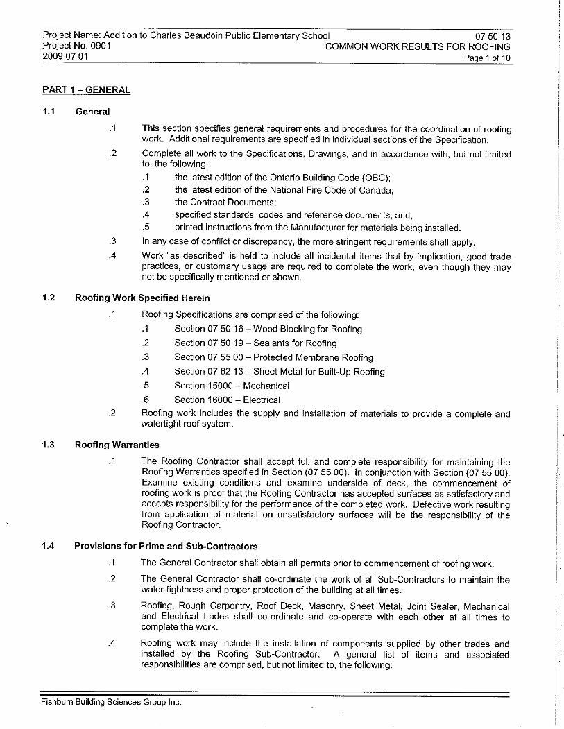
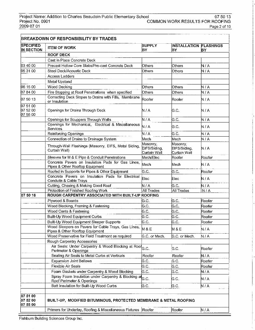
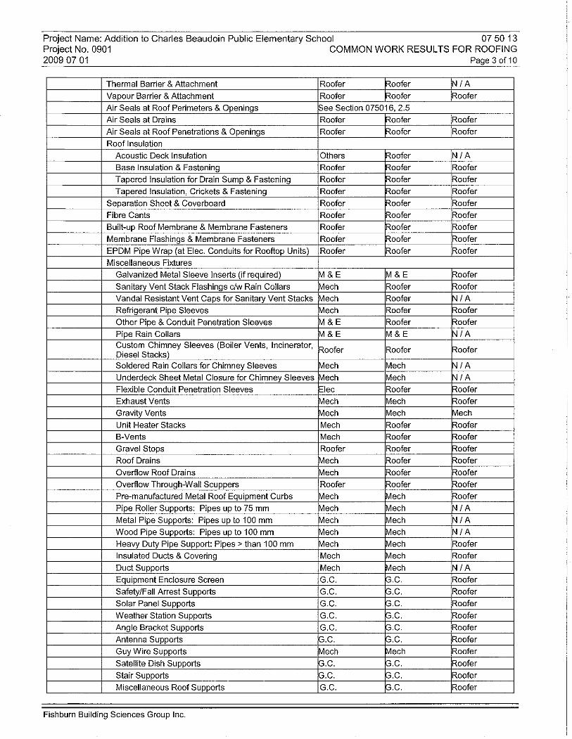
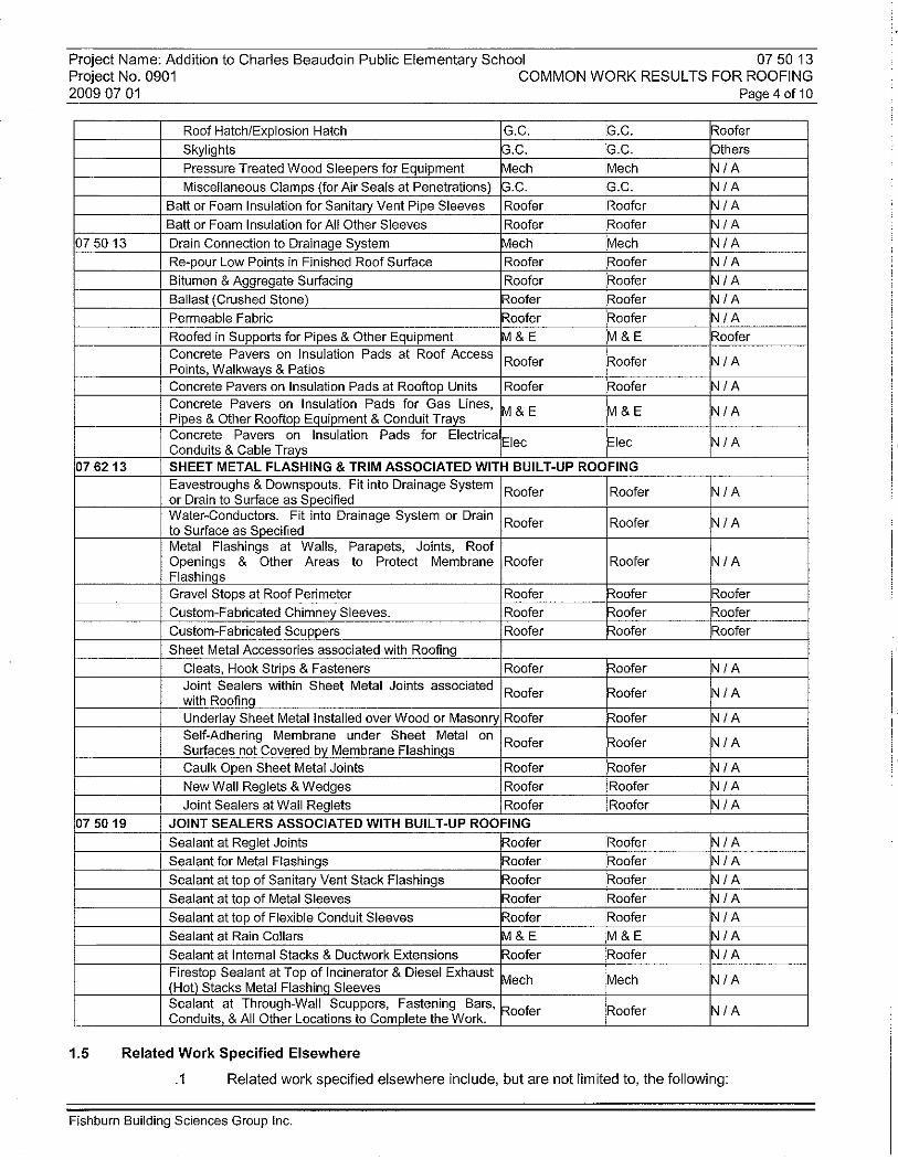

Project Name: Addition to Charles Beaudoin Public Elementary School 07 50 16 Project No. 0901 WOOD BLOCKING FOR ROOFING 2009 07 01 Page 1 of 9
PART 1 – GENERAL
1.1 General
.1 This section specifies general requirements and procedures for rough carpentry related to built-up roofing. Additional requirements may be specified in individual sections of the Specification.
.2 All conditions of the Contract and Division 1 apply to this section.
.3 Coordinate work of this section with related work specified in other sections to ensure construction schedule and protection of finished work is maintained at all times.
.4 All rough carpentry work of this section to be completed by the General Contractor.
1.2 Description of Work
.1 Complete all work as specified in the Summary of Work, Specifications and Drawings.
.2 Work of this section includes the supply and installation of all rough carpentry work associated with roofing, including wood blocking, and wood sleepers for equipment, rooftop units and pipe supports.
.3 Work of this section also includes the supply and installation of air seals under wood blocking at all locations including, but not limited to, perimeters, curbs, wall/roof transitions and nailers, and as shown on the Drawings.
.4 Work “as described” is held to include all incidental items that by implication, good trade practices, or customary usage are required to complete the work, even though they may not be specifically mentioned or shown.
.5 Additional requirements may be specified in individual sections of the Specification and/or shown on the Drawings.
1.3 Related Work Specified Elsewhere
.1 Section 05 00 00 – Metal Upstands
.2 Section 07 50 13 – Common Work Results for Roofing
.3 Section 07 50 19 – Sealants for Roofing
.4 Section 07 55 00 – Protected Membrane Roofing
.5 Section 07 62 13 – Sheet Metal for Built-Up Roofing
.6 Section 15000 – Mechanical
.7 Section 16000 – Electrical
1.4 References
The latest edition of all Standards shall apply if the referenced standards have been superseded. .1 ASTM A153/A153M-05 Zinc Coating (Hot-Dip) on Iron and Steel Hardware. .2 ASTM C553-02 Mineral Fiber Blanket Thermal Insulation .3 ASME B18.6.1 – 1981 Wood Screws (Inch Series).
(Supersedes CSA B35.4 - 1972) .4 ASME B18.6.4 – 1999 Thread Forming and Thread Cutting Tapping
(Supersedes CSA B35.3 - 1969) Screws and Metallic Drive Screws, Inch Series. .5 CSA B111-1974 (R2003) Wire Nails, Spikes and Staples. .6 CAN/CSA-G164-M92 (R2003) Hot Dip Galvanizing of Irregularly Shaped Articles. .7 CSA O80.2-97 Pressure Treatment of Lumber, Timber, Bridge
Ties and Mine Ties. .8 CSA O80.5-97 Pressure Treatment of Posts. .9 CSA O80.9 Pressure Treatment of Plywood.
Fishburn Building Sciences Group Inc.
Project Name: Addition to Charles Beaudoin Public Elementary School 07 50 16 Project No. 0901 WOOD BLOCKING FOR ROOFING 2009 07 01 Page 2 of 9
.10 CSA O121-M1978 (R2003) Douglas Fir Plywood.
.11 CAN/CSA-O141-05 Softwood Lumber.
.12 CSA O151-04 Canadian Softwood Plywood.
.13 CAN/CGSB-37.29-M89. Rubber-Asphalt Sealing Compound.
.14 CAN/ULC-S702-97 Thermal Insulation, Mineral Fibre for Buildings.
.15 CAN/ULC-S705.1-01 & Thermal Insulation, Spray Applied CAN/ULC-S705.2-98 Rigid Polyurethane Foam.
.16 National Lumber Grades Authority (NLGA), Standard Grading Rules for Canadian Lumber, 2004.
1.5 Qualifications
.1 Employ only experienced and qualified workers that can provide quality results. Replace all work that results from inferior products or installation.
1.6 Examination
.1 Examine surfaces and report any adverse conditions that could negatively impact the appearance and performance of the work.
1.7 Coordination
.1 Coordinate work of this section with related work specified in other sections to ensure that the construction schedule, water-tightness, and protection of the building and work is maintained at all times.
1.8 Submittals
.1 Submit to the Consultant a list of materials intended for use, before they are ordered.
.2 If applicable submit Pull-Out Test results for fasteners before proceeding with the work.
.3 Submittals shall be in accordance with Section (07 55 00).
.4 Additional requirements may be specified in other sections of the Specifications.
1.9 Shop Drawings, Product Data, Samples and Mock-ups
.1 Construct mock-ups for review before proceeding with the work, including but not limited to the following: .1 Wood blocking system at an inside corner, and .2 Wood blocking system at an outside corner.
.2 Include in the mock-up air seals for each profile.
.3 Inspect all intersecting and adjoining elevations to ensure that continuity of roofing and air seals can be achieved. Verify attachment, methods for securing and pullout strengths to ensure that work can resist the anticipated loads and will remain in place against all wind, weather and service conditions without warping or deforming.
.4 Submittals shall be in accordance with Section (07 55 00).
.5 Additional requirements may be specified in other sections of the Specifications.
1.10 Delivery, Storage and Handling
.1 Provide and maintain dry raised weatherproof storage.
.2 Protect materials from weather at all times.
.3 Remove only as much material as can be incorporated, covered and made watertight in the same work period.
.4 Use dry material only. Remove from site any materials that have been exposed to rain, snow or ice.
Fishburn Building Sciences Group Inc.
Project Name: Addition to Charles Beaudoin Public Elementary School 07 50 16 Project No. 0901 WOOD BLOCKING FOR ROOFING 2009 07 01 Page 3 of 9
1.11 Environmental and Safety Requirements
.1 Ensure at all times protection of the building and any unfinished work that can be damaged by inclement weather.
.2 If inclement weather is forecast or appears imminent, postpone work that would risk the work or building being damaged by moisture.
.3 If it becomes apparent that work would threaten the buildings water tightness, the Owner has the right to stop the work. Any additional expenses due to work stoppage or postponement of the work will be at the Contractor’s expense.
.4 Ensure at all times protection of materials and equipment that are sensitive to damage by moisture.
.5 Install products sensitive to damage by moisture, snow or fog only when weather permits. Observe Manufacturer’s printed recommendations regarding temperature and weather conditions.
.6 As governed by design intent, apply each part of roofing system only when surfaces and weather allow for a successful application and performance of completed work.
.7 When temperatures are below 5°C (40°F), proceed with work only with the mutual documented agreement between the Contractor and material supplier that, with the materials and method used, the specified installation under the conditions can be successfully achieved.
1.12 Inspection and Testing
.1 Field review of the work will be completed by Fishburn Building Sciences Group Inc. (Consultant).
.2 Examination of materials' certificates and test reports shall not be construed as relieving the Contractor of his responsibility for proper completion and guarantee of the work in accordance with the Drawings and Specifications.
.3 Notify the Architect/Owner/Consultant and material Manufacturer at least 48 hours before roofing operations commence, and arrange for a site meeting for discussion of procedure. Subsequently, give two working days prior notice for the commencement of each phase of work. Notify of delays and re-starts.
.4 Cooperate with Consultant and afford all facilities necessary to permit full inspection of the work and testing of materials prior to, during their use and during the warranty period. Act immediately on instructions given. Make cut-out for testing purposes when and where required and make good roofing of test areas and of any and all defects of materials and workmanship without additional cost.
.5 Do not conceal or cover any phase of the work until after it has been inspected and approved.
.6 Inspection of the Contract Documents as to extent of work, quality of workmanship and materials, methods, etc. is the responsibility of the Architect.
1.13 Non-Compliance with Inspections and Tests
.1 If the initial inspection and tests required to establish compliance with the Contract Documents indicates non-compliance with the Contract Documents, subsequent tests or re-inspection occasioned by non-compliance shall be performed. The cost of re-inspection and testing will be borne by the Contractor and deducted from the price of the Contract.
.2 The Contractor shall replace or correct defective work not done in accordance with the Contract. If, in the opinion of the Architect, it is not expedient to correct defective work or work done in accordance with the Contract, the Owner may deduct from the Contract price the difference in value between the work as done and called for by the Contract, the amount of which will be determined by the Architect.
.3 Replace all work that results from inferior products or workmanship.
Fishburn Building Sciences Group Inc.
Project Name: Addition to Charles Beaudoin Public Elementary School 07 50 16 Project No. 0901 WOOD BLOCKING FOR ROOFING 2009 07 01 Page 4 of 9
1.14 Contractor Quality Control
.1 The Contractor shall appoint a worker for the purpose of quality control on the construction site (Quality Control Inspector) to ensure that the work is installed in accordance with the Contract, Specifications and Drawings.
.2 In addition to procedures that may be specified elsewhere, on drawings provided by the Consultant, the Contractor’s Quality Control Inspector shall maintain a Roof Plan showing the following record of construction: .1 The progress and limits of each day’s work.
.3 In addition to procedures that may be specified elsewhere, the Contractor’s Quality Control Inspector shall maintain written records of the following: .1 A written record of the workers on site. .2 A written record of changes that affect the work (i.e. site instructions, change
orders, addenda, etc.). .3 A written record of materials shipped to and incorporated in the work including
dates, name of Manufacturer, type of material, lot and serial numbers and compliance standards as written on the labels.
.4 In addition to procedures that may be specified elsewhere, the Contractor’s Quality Control Inspector shall make available on a daily basis the following: .1 Labels showing serial and lot numbers for each type and lot of materials. .2 Samples required by the specifications.
.5 The Contractor’s Quality Control Inspector shall provide a copy of “as built” drawings at the end of the project: .1 On two sets of white prints provided by the Consultant, maintain Project Record
Drawings that accurately record deviations from Contract documents, including field changes of dimensions, details and changes made by Change Orders.
.2 Record changes on one set of prints in red. At completion of project and prior to final inspection, transfer changes to second set and submit both sets to the Consultant.
1.15 Warranty
.1 The work of this section shall be included in the warranty as specified in Section (07 55 00).
1.16 Final Cleaning
.1 Clean the roof and drainage system free of debris at project completion.
.2 Schedule cleaning operations so that resulting dust, debris and other contaminants do not fall on or damage completed work.
.3 Leave roof, building and landscape free of debris.
.4 Removal all surplus materials and equipment from the site.
.5 Make good and pay all costs and fees required to rectify damage caused by the work
PART 2 – PRODUCTS
2.1 Lumber Material
.1 All lumber sizes are specified and shown as “Surfaced Dry”, nominal.
Fishburn Building Sciences Group Inc.
Project Name: Addition to Charles Beaudoin Public Elementary School 07 50 16 Project No. 0901 WOOD BLOCKING FOR ROOFING 2009 07 01 Page 5 of 9
.2 Sizes, grading requirements and quality control to CSA O121-M1978 (R2003), CAN/CSA-O141-05 and CSA O151-04.
.3 Grades and Commercial Species Groups to NLGA Standard Grading Rules for Canadian Lumber, 2004.
.4 Lumber identification: by grade stamp of an agency certified by Canadian Lumber Standards Accreditation Board.
.5 Plywood identification: by grade mark in accordance with applicable CSA Standards.
.6 Plywood: As specified and/or shown on the Drawings. Douglas Fir Plywood (DFP). To CSA O121-M1978 (R2003). Thickness as specified and/or shown on the Drawings, minimum 15.5 mm (0.625”).
.7 Blocking and Rough Framing: As specified and/or shown on the Drawings. To CAN/CSA-O141-05. Size as specified and/or shown on the Drawings. 1. Dimension Lumber – 38 mm to 89 mm (2" to 4" nom.) thick and wide: Grade
Category: “Light Framing”. Grade: “Construction”. 2. Dimension Lumber – 38 mm to 89 mm (2" to 4" nom.) thick, 114 mm (5" nom.) or
more wide: Grade Category:”Structural Joists and Planks”. Grade: “No.2 and Better”.
3. Timber – 140 mm (6" nom.) min. thickness in its smallest dimension: Grade Category: “Posts and Timbers”. Grade: “Standard”.
.8 Wood Cants: As specified and/or shown on the Drawings. To CAN/CSA-O141-05. Grade Category: “Light Framing”. Grade: “Construction”. Size: 89 mm x 89 mm (4” x 4” nom.), unless otherwise shown on the Drawings.
2.2 Pressure Treatment
.1 Use pressure treated material for exposed applications and when specified or specifically shown on the Drawings.
.2 Pressure Treat with Chromated Copper Arsenate (CCA), Alkaline Copper Quaternary (ACQ) or Copper Azole (CA), to CSA 080.2-97, 080.5-97 and 080.9-97.
2.3 Wood Preservative for Field Treatment
.1 Field treat using the same preservative with which wood was originally pressure treated, to CSA 080.2-97 to obtain wet retention of 64 kg/m3 (4 lbs/ft3) of wood. Colour green.
2.4 Fasteners
.1 All nails and spikes to meet CSA B111-1974 (R2003)
.2 All tapping and driving screws to meet ASTM B18.6.4 - 1999.
.3 All wood screws to meet ASTM B18.6.1 – 1981.
.4 All galvanizing to meet ASTM A153/A153M-05 and CAN/CSA-G164-M92.
.5 All fasteners, size and spacing to meet the most stringent requirements of this section, the Drawings, the Ontario Building Code or Factory Mutual requirements.
.6 Pressure Treated Wood: When pressure treated wood blocking is specified, use minimum No. 304 stainless steel fasteners.
.7 Plywood Deck and Board Lumber Deck: Galvanized spiral nails or No. 10 flat head screws, 50 mm (2”) long.
.8 Wood to Wood Nails & Spikes: Galvanized spiral to CSA Standard B111-1974, of sufficient lengths so that not less than half the length protrudes completely into the underlying member. Screws: Galvanized, #7 flat head to CSA Standard 1335.4-1972 and ANSI B18.6.1-1981 and of sufficient length to completely penetrate through bases minimum 13 mm (0.5”). Nails and screws shall be a minimum 3.2 mm (0.125”) in diameter. Fasteners for plywood sheathing shall be minimum 50 mm (2”) in length.
Fishburn Building Sciences Group Inc.
Project Name: Addition to Charles Beaudoin Public Elementary School 07 50 16 Project No. 0901 WOOD BLOCKING FOR ROOFING 2009 07 01 Page 6 of 9
.9 Wood to Steel Deck: Secure bottom nailer with minimum two rows of #10, 6 mm (0.25”) galvanized steel screws at maximum spacing of 600 mm (2’-0”). Screws shall be sufficient length to penetrate top flute of decking a minimum 13 mm (0.5”) and a maximum of 19 mm (0.75”). Screws to be factory coated with an additional corrosion protection equivalent to Rawl Perma-Seal or better.
.10 Wood to Lightweight Concrete Deck, Brick or Hollow Masonry: Rawl toggle bolt, Permagrip TL, Zamac Nail-in or Rawlite fasteners as recommended by the Manufacturer. Length to ensure a minimum embedment of 25 mm (1”) and maximum 62 mm (2.5”) as per Manufacturer’s recommendations. Generally, provide fastener length 2.5 times the thickness of material to be secured.
.11 Wood to Concrete: Tapgrip, Permagrip, or Rawl Spike 6 mm (0.25”) diameter screws. Length to provide a minimum 32 mm (1.25”) and maximum 40 mm (1.6”) embedment into substrate as required. Drill holes 13 mm (0.5”) deeper than depth of fastener penetration. Type to be approved subject to results of pull tests.
.12 Wood Sleepers: Use galvanized steel bolts with washers, minimum 10 mm (0.375”) diameter.
.13 Washers, Nuts and Bolts: Hot-dipped galvanized or Type 304 stainless steel, to match fastener material.
.14 Adhesive Anchors: M-16 HILTI HVA size noted on the drawings or size recommended by Manufacturer. Co-ordinate selection of fastener with Manufacturer of item to be secured and obtain Structural Engineers approval and written consent before proceeding.
.15 Metal to Wood or Masonry: Use #10 cadmium plated hex head screws with neoprene and steel washers by Atlas Bolt or approved equal. Minimum length 38 mm (1.5”). Use lead shields, Rawl or equal as required for anchoring. Colour of screw head to meet approval of Consultant. Provide touch-up paint as required to coat all exposed surfaces of screws damaged during the driving process.
.16 Proprietary Fasteners: Toggle bolts, expansion shields and lag bolts, screws and lead or inorganic fibre plugs to suite site conditions.
2.5 Accessories
.1 Cement Board: Supra-Deck F by Finex Inc. (1-800-GoFinex), 6 mm (0.25"), or approved equal as shown on the Drawings.
.2 Air Seal on Steel Deck: Use 26-gauge galvanized or pre-finished sheet metal to suit profile covered with SOPRAVAP’R by Soprema or approved equal, or SOPRAVAP’R by Soprema or approved equal, as shown on the Drawings.
.3 Air Seal on Wood, Concrete, Lightweight Concrete or Thermal Barrier: Use 26-gauge galvanized or pre-finished sheet metal to suit profile, or 26-gauge galvanized or pre-finished sheet metal to suit profile covered with SOPRAVAP’R by Soprema or approved equal, or self-adhering modified bitumen base sheet, or Sopraseal Stick 1100 by Soprema or approved equal, or extend the bitumen vapour barrier, as shown on the Drawings.
.4 Expansion Joint Bellows: Use 26-gauge galvanized sheet metal plate covered with SOPRAVAP’R or Sopraseal Stick 1100, by Soprema, or approved equal, as shown on the Drawings.
.5 Flexible Air Seals: Use FR-40 PVC membrane by Lexcor Roofing Products or approved equal, as shown on the Drawings.
.6 Foam Gasket: Use 6 mm (0.25”) thick by size shown on the Drawings, Ethafoam by Dow Chemical or approved equal.
.7 Two-Component Spray-in-Place Polyurethane Foam Insulation: to CAN/ULC-S705.1-01 and CAN/ULC-S705.2-98, as required and/or shown on the Drawings.
.8 Caulk: To Section 07 50 19.
.9 Rubberized Mastic: One component synthetic rubber – Cold Gold flashing cement by IKO or approved equal.
Fishburn Building Sciences Group Inc.
Project Name: Addition to Charles Beaudoin Public Elementary School 07 50 16 Project No. 0901 WOOD BLOCKING FOR ROOFING 2009 07 01 Page 7 of 9
.10 Batt Insulation: At Built-Up Wood Curbs and Blocking: Mineral wool fibre, with density 40 kg/m3 (2.5 lb/ft3), to CAN/ULC-S702-97 and ASTM C553-02, ROXUL AFB or approved equal, thickness as specified and/or shown on the Drawings.
PART 3 – EXECUTION
3.1 Examination
.1 Do not install wood blocking, air seals, vapour barrier or underlay until surface to be covered has been installed and inspected.
.2 Inspect work and advise the Architect of conditions that would adversely affect the work of this trade.
.3 Commencement of work is proof that the Contractor has accepted surfaces as satisfactory for intended operations and accepted responsibility for appearances and performances of completed work.
.4 Defective work resulting from work on unsatisfactory surfaces will be considered the responsibility of those performing the work of this section.
.5 Repair damaged and inferior work caused by work of this Contract with materials and finish to match the original.
3.2 Preparation
.1 When pressure treated materials are used, protect all cuts, holes and injuries by liberally applying wood preservative before installation.
.2 Apply preservative by dipping or brushing, completely saturating and maintaining wet film on the surface for a minimum 3-minute soak on lumber or 1-minute soak on plywood.
3.3 Installation
.1 Provide carpentry alterations and comply with best practices of the trade.
.2 Do not install wood blocking, air seals, vapour barrier, or underlay until the surface to be covered has been installed and inspected
.3 Drawings are in part descriptive; therefore, do not regard blocking, air seals or fastening provisions shown as exact or complete. Provide required provisions for air seal fastening, located and secured to suit site conditions and adequate for intended support.
.4 Lay out work conforming to Details. Cut and fit accurately. Align, level, square, plumb and secure work permanently in place. Join wood over solid backing. Allow 3 mm (0.125”) gap between ends of plywood sheets for expansion purposes.
.5 Offset joints of adjoining plywood or wood blocking a minimum of 1200 mm (4’-0”). Install sheathing with surface grain perpendicular to vertical framing members.
.6 Install foam gasket under wood blocking at locations shown on the Drawings.
.7 Install air seals at the roof perimeter and at all openings to ensure continuity of the roof and building’s airtight envelope.
.8 Provide metal bellows at expansion joints as shown on the Drawings.
.9 Extend air seals up vertical surfaces a minimum 50 mm (2”) above the cant strip and onto the roof deck a minimum 100 mm (4”), or minimum 100 mm (4”) beyond insulation stops where insulation stops are provided, unless otherwise shown on the Drawings to be carried further.
.10 Extend metal air seals up metal curbs a minimum 50 mm (2”) and onto the roof deck a minimum 100 mm (4”), or minimum 100 mm (4”) beyond insulation stops where insulation stops are provided, unless otherwise shown on the Drawings to be carried further. Seal metal air seals to metal curbs with continuous bead of polyurethane sealant.
Fishburn Building Sciences Group Inc.
Project Name: Addition to Charles Beaudoin Public Elementary School 07 50 16 Project No. 0901 WOOD BLOCKING FOR ROOFING 2009 07 01 Page 8 of 9
.11 When metal air seals are used, mitre and overlap corners and end joints a minimum of 50 mm (2”) and seal all overlaps and corners with modified bitumen sealant. Install additional ply of self-adhering membrane overlapping joints minimum 150 mm (6”).
.12 Where irregular surfaces interfere with the proper installation of the metal air seal, keep metal back and where required install flexible membranes. Overlap flexible membrane onto metal air seal minimum 75 mm (3”) and seal solid with modified sealant. Where metal or flexible air seals cannot provide continuity of the building’s airtight envelope, install two-component polyurethane foam to ensure continuity and air tightness.
.13 Install wood cant strips and blocking at locations shown on the Drawings. Back-cut as required to accommodate anchors, slopes, or uneven surfaces. Trim and level to accommodate cambers, slopes, insulation, roofing and flashings In accordance with design intent. Secure permanently to the structure to prevent warping under service conditions.
.14 Build up wood blocking at all curbs a minimum of 450 mm (18”) above the deck, unless shown on the Drawings to be higher.
.15 Build up wood blocking at all expansion and control joints a minimum of 300 mm (12”) above the finished roof surface.
.16 Notch wood blocking and cants as required around anchor points or irregular surfaces to achieve design intent. Back or face cut wood blocking with 3 mm (0.125”) relief cuts as required to ensure blocking conforms to curves or unusual slopes or shapes. Do not impair the wood blocking’s structural integrity or service function.
.17 Offset and countersink all fasteners flush with surface of wood blocking being secured.
.18 Level the top of curbs and sleepers to compensate for roof slope.
.19 Slope the top of all wood blocking at the roof perimeter in towards the roof at a minimum of 2:12, unless otherwise shown on the Drawings.
.20 Remove all sharp edges that could damage materials.
.21 Make good any damage or interior areas necessary as a result of work of this section.
3.4 Securement
.1 Comply with the most stringent requirements as required by this section, the Drawings, Building Code or Factory Mutual requirements. Increase number and spacing of all fasteners by 50% 2400 mm (8’-0”) from the corners of the roof.
.2 Install fasteners to the design intent to hold all wood blocking permanently in place to prevent warping and deflection and to resist all wind and weather conditions.
.3 Use specified fasteners.
.4 The type, length and spacing of fasteners may be subject to pull out test results.
.5 All fasteners shall be placed minimum 10 mm (0.325”) from any edge.
.6 Install fasteners in two rows in the direction of the grain, with each fastener offset one another in a staggered fashion by approximately 50%.
.7 Except when bolted in place, install two additional fasteners 75 mm (3”) from all joints.
.8 Stagger fasteners between layers of wood when more than 1 layer of wood is to be installed. Minimum penetration to be 32 mm (1.25”). Secure top nailers to bottom nailers staggered at not less than 450 mm (18”) o.c.
.9 Plywood Deck: Secure with nails or screws. Install fasteners at 150 mm (6") o.c. at edges and 300 mm (12") o.c. in the field of the sheet.
.10 Board Lumber Deck: Secure with nails or screws. Two per support for board up to 200 mm (8”) wide, three per support for board up to 300 mm (12”) wide.
.11 Wood Cants: Secure with nails or screws. Install fasteners at 450 mm (18”) o.c. .12 Wood Components to Wood Components and Deck:
1. Install fasteners staggered at not less than 450 mm (18”) o.c.
Fishburn Building Sciences Group Inc.
Project Name: Addition to Charles Beaudoin Public Elementary School 07 50 16 Project No. 0901 WOOD BLOCKING FOR ROOFING 2009 07 01 Page 9 of 9
Fishburn Building Sciences Group Inc.
2. Reduce the spacing of fasteners to 300 mm (12”) o.c. for a distance of 3000 mm (10’-0”) from all inside and outside corners at the roof’s perimeter.
.13 Wood Components to Concrete, Lightweight Concrete, Brick or Hollow Masonry: 1. Pre-drill holes 13 mm (0.5") deeper than fastener penetration. 2. Install fasteners staggered at not less than 600 mm (24”) o.c. 3. Reduce the spacing of fasteners to 300 mm (12”) o.c. for a distance of 3000 mm
(10’-0”) from all inside and outside corners at the roof’s perimeter. 4. When bolts are used to secure wood blocking, recess washers and bolts below the
finished surface. .14 Wood Components to Metal Components and Steel Deck:
1. Install fasteners staggered at not less than 450 mm (18”) o.c. 2. Reduce the spacing of fasteners to 300 mm (12”) o.c. for a distance of 3000 mm
(10’-0”) from all inside and outside corners at the roof’s perimeter. .15 Pull-Out Tests: When security of fasteners appears to be in doubt, in consultation with the
Consultant and fastener supplier, provide pull out tests at a minimum of five locations for each type of material and fastener being employed. Submit results to Consultant and act on Manufacturer’s written recommendations on the type, length and spacing of fasteners to hold the member being secured permanently in place, and to prevent warping, deflection or displacement of materials against all wind and weather conditions. Minimum pull out resistance of each fastener to be 45 kg. (100 lb.). Submit summary of findings to the Consultant for review before proceeding.
END OF SECTION 07 50 16
Project Name: Addition to Charles Beaudoin Public Elementary School 07 50 19 Project No. 0901 SEALANTS FOR ROOFING 2009 07 01 Page 1 of 5
PART 1 – GENERAL
1.1 General
.1 This section specifies general requirements and procedures for joint sealers related to built-up roofing. Additional requirements may be specified in individual sections of the Specifications.
.2 All conditions of the Contract and Division 1 apply to this section.
.3 Coordinate work of this section with related work specified in other sections to ensure construction schedule and protection of finished work is maintained at all times.
1.2 Description of Work
.1 Complete all work as specified in the Summary of Work, Specifications and Drawings.
.2 Work of this section includes the supply and installation of sealants in all exterior building joints, aluminum and glazing joints, reglet joints, “S” lock joints, raised lock seams, metal flashings, vent stack flashings, metal sleeves, rain collars, chimney sleeves, through-wall scuppers, fastening bars, conduits, internal stacks, ductwork, door thresholds and at all other locations where sealants are required or shown on the Drawings to provide a complete and finished system by reference or implication.
.3 Work of this section also includes the supply and installation of firestop sealant to ULC List of Equipment and Materials, Firestop Systems and Components, 2004 Edition system designation at mechanical penetrations in firewalls, when specified in the Summary of Work and/or as shown on the Drawings.
.4 Work includes cutting and cleaning of reglet joints, preparing substrate surfaces, installing joint backing, primer and sealant.
.5 Work “as described” is held to include all incidental items that by implication, good trade practices, or customary usage are required to complete the work, even though they may not be specifically mentioned or shown.
.6 Additional requirements may be specified in individual sections of the Specifications and/or shown on the Drawings.
1.3 Related Work
.1 Roofing Specifications are comprised of the following: 1. Section 07 50 13 – Common Work Results for Roofing 2. Section 07 50 16 – Wood Blocking for Roofing 3. Section 07 55 00 – Protected Membrane Roofing 4. Section 07 62 13 – Sheet Metal for Built-Up Roofing 5. Section 15000 – Mechanical 6. Section 16000 – Electrical
1.4 References
The latest edition of all Standards shall apply if the referenced standards have been superceded. .1 CAN/CGSB-19.13–M87 Sealing Compound, One Component, Elastomeric,
Chemical Curing. .2 CAN/ULC-S115-05 Standard Method of Fire Tests of Firestop Systems. .3 ULC List of Equipment and Materials,
Firestop Systems and Components, 2004 Edition.
1.5 Qualifications
Fishburn Building Sciences Group Inc.
Project Name: Addition to Charles Beaudoin Public Elementary School 07 50 19 Project No. 0901 SEALANTS FOR ROOFING 2009 07 01 Page 2 of 5
.1 Employ only experienced and qualified workers that can provide quality results. Replace all work that results from inferior products or installation.
1.6 Examination
.1 Examine surfaces and report any adverse conditions that could negatively impact the appearance and performance of the work.
1.7 Coordination
.1 Coordinate sealant work with related work specified in other sections to ensure that the construction schedule, water-tightness, and protection of the building and work are maintained at all times.
1.8 Shop Drawings, Product Data, Samples and Mock-ups
.1 Before proceeding with fabrication, provide a mock-up of each joint profile to be sealed showing size, shape, depth of joint, back-up material, primer and sealant. Mock-up may be part of finished work.
.2 Submittals shall be in accordance with Section (07 55 00).
.3 Additional requirements may be specified in other sections of the Specifications.
1.9 Delivery, Storage and Handling
.1 Deliver and store materials in original wrappings and containers with Manufacturer’s seals and labels, intact. Protect from freezing, moisture, water and contact with ground or floor.
1.10 Environmental and Safety Requirements
.1 Conform to Manufacturer’s recommended temperatures, relative humidity and substrate moisture content for application and curing of sealants, including special conditions governing use.
.2 In confined spaces, provide a portable supply of outside air and exhaust fans to ensure that fumes will not impact workers or building occupants.
.3 Remove all rubbish and surplus materials from the job site on a daily basis.
1.11 Inspection and Testing
.1 Field review of the work will be completed by Fishburn Building Sciences Group Inc. (Consultant).
.2 Examination of materials' certificates and test reports shall not be construed as relieving the Contractor of his responsibility for proper completion and guarantee of the work in accordance with the Drawings and Specifications.
.3 Notify the Architect/Owner/Consultant and material Manufacturer at least 48 hours before roofing operations commence, and arrange for a site meeting for discussion of procedure. Subsequently, give two working days prior notice for the commencement of each phase of work. Notify of delays and re-starts.
.4 Cooperate with Consultant and afford all facilities necessary to permit full inspection of the work and testing of materials prior to, during their use and during the warranty period. Act immediately on instructions given. Make cut-out for testing purposes when and where required and make good roofing of test areas and of any and all defects of materials and workmanship without additional cost.
.5 Do not conceal or cover any phase of the work until after it has been inspected and approved.
.6 Inspection of the Contract Documents as to extent of work, quality of workmanship and materials, methods, etc. is the responsibility of the Architect.
Fishburn Building Sciences Group Inc.
Project Name: Addition to Charles Beaudoin Public Elementary School 07 50 19 Project No. 0901 SEALANTS FOR ROOFING 2009 07 01 Page 3 of 5
1.12 Non-Compliance with Inspections and Tests
.1 If the initial inspection and tests required to establish compliance with the Contract Documents indicates non-compliance with the Contract Documents, subsequent tests or re-inspection occasioned by non-compliance shall be performed. The cost of re-inspection and testing will be borne by the Contractor and deducted from the price of the Contract.
.2 The Contractor shall replace or correct defective work not done in accordance with the Contract. If, in the opinion of the Architect, it is not expedient to correct defective work or work done in accordance with the Contract, the Owner may deduct from the Contract price the difference in value between the work as done and called for by the Contract, the amount of which will be determined by the Architect.
.3 Replace all work that results from inferior products or workmanship.
1.13 Contractor Quality Control
.1 The Contractor shall appoint a worker for the purpose of quality control on the construction site (Quality Control Inspector) to ensure that the work is installed in accordance with the Contract, Specifications and Drawings.
.2 In addition to procedures that may be specified elsewhere, on Drawings provided by the Consultant, the Contractor’s Quality Control Inspector shall maintain a Plan showing the following record of construction: .1 The progress and limits of each day’s work.
.3 In addition to procedures that may be specified elsewhere, the Contractor’s Quality Control Inspector shall maintain written records of the following: .1 A written record of the workers on site. .2 A written record of changes that affect the work (i.e. site instructions, change
orders, addenda, etc.). .3 A written record of materials shipped to and incorporated in the work including
dates, name of Manufacturer, type of material, lot and serial numbers and compliance standards as written on the labels.
.4 In addition to procedures that may be specified elsewhere, the Contractor’s Quality Control Inspector shall make available on a daily basis the following: .1 Labels showing serial and lot numbers for each type and lot of materials. .2 Samples required by the Specifications.
1.14 Warranty
.1 The work of this section shall be included in the warranty as specified in Section (07 55 00).
1.15 Final Cleaning and Painting
.1 To Section (07 55 00).
PART 2 – PRODUCTS
2.1 Materials
.1 Unless otherwise specified: .1 Polyurethane Sealant: For use with reglets, sheet metal flashings, raised lock
seams, vent stack flashings, metal sleeves, rain collars, chimney sleeves, through-wall scuppers, fastening bars, conduits, internal stacks, ductwork, door thresholds, exterior precast and masonry joints and other exterior uses, use 1-part moisture-curing polyurethane compound, non-staining, non-bleeding, Tremco Dymonic or approved equal, to CAN/CGSB-19.13-M87, Type II. Where exposed to view, use
Fishburn Building Sciences Group Inc.
Project Name: Addition to Charles Beaudoin Public Elementary School 07 50 19 Project No. 0901 SEALANTS FOR ROOFING 2009 07 01 Page 4 of 5
colour to match adjacent materials as close as possible and selected from Manufacturer's standard colour chart where exposed to view.
.2 Silicone: For “S” lock joints, aluminum and glazing joints and EIFS, use 1-part silicone base, solvent curing, “Spectrum 2” by Tremco or approved equal, to CAN/CGSB-19.13-M87.
.3 Firestop Sealant: By Tremco, Dow Corning Canada Inc., GE Silicone, 3M Corporation or approved equal, to CAN/ULC-S115-05.
.2 Joint Cleaner: Non-corrosive, non-staining, non-porous type, compatible with joint forming materials and sealant, recommended by sealant Manufacturer.
.3 Joint Backing: Round, extruded polyethylene foam rod, closed cell, Shore A Hardness 20, tensile strength 140 to 210 kilopascals. Oversize 30% larger than joint width.
.4 Bond Breaker Tape: Pressure sensitive tape that will not bond to caulking, as recommended by Manufacturer.
.5 Primer: Non-staining type, as recommended by Sealant Manufacturer.
PART 3 – EXECUTION
3.1 Protection
.1 Protect installed work of other trades from staining or contamination.
3.2 Preparation of Joint Surfaces
.1 Prepare surfaces in accordance with Manufacturer’s directions.
.2 Examine joint sizes and conditions to establish correct depth-to-width relationship for installation of backup materials and sealants.
.3 Clean bonding joint surfaces of harmful substances including dust, rust, oil, grease and other foreign matter, which may impair work.
.4 Do not apply sealants to joint surfaces treated with sealer, curing compound, water repellent, or other coatings unless tests have been performed to ensure compatibility of materials. Remove coatings as required.
.5 Ensure joint surfaces are dry and frost free.
3.3 Cleaning
.1 Clean and solvent wipe surfaces with joint cleaner prior to priming and caulking.
3.4 Priming
.1 Prime joints in accordance with Manufacturer's instructions.
.2 Where necessary to prevent staining, mask adjacent surfaces prior to priming and caulking.
.3 Conduct adhesion tests to determine whether primer is required for pre-finished metal surfaces.
.4 Prime copper, concrete and masonry surfaces to receive sealant.
.5 Prime sides of joints in accordance with sealant Manufacturer’s instructions immediately prior to caulking.
3.5 Backup Material
.1 Apply bond breaker tape or joint filler, as required to Manufacturer’s instructions.
.2 Install joint filler to achieve correct joint depth and shape, with approximately 30% compression.
Fishburn Building Sciences Group Inc.
Project Name: Addition to Charles Beaudoin Public Elementary School 07 50 19 Project No. 0901 SEALANTS FOR ROOFING 2009 07 01 Page 5 of 5
Fishburn Building Sciences Group Inc.
3.6 Mixing
.1 Where required, mix materials in strict accordance with sealant Manufacturer’s instructions.
3.7 Application
.1 Install sealant in accordance with Manufacturer's instructions.
.2 Apply sealant when air and substrate temperatures are within the application range recommended by the Manufacturer. Do not work during inclement weather.
.3 Mask edges of joint where irregular surface or sensitive joint border exists to provide a neat joint.
.4 Apply sealant in continuous beads.
.5 Apply sealant using gun with proper size nozzle.
.6 Use sufficient pressure to fill voids and joints solid.
.7 Form surface of sealant with full bead, smooth, free from ridges, wrinkles, sags, air pockets and embedded impurities.
.8 Tool exposed surfaces before skinning begins to give slightly concave shape.
.9 Remove excess compound promptly as work progresses and upon completion.
.10 Apply sealant in "S" locks of metal flashings as it is installed. Apply to the bottom and top and sides before the metal is pushed into the joint. Clean off all excess material visible after flashing is installed.
3.8 Curing
.1 Cure sealants in accordance with sealant Manufacturer’s instructions.
.2 Do not cover up sealants until proper curing has taken place.
.3 Protect sealants until cured.
3.9 Cleanup
.1 Clean adjacent surfaces immediately and leave work neat and clean.
.2 Remove excess droppings as work progresses, using recommended cleaners.
.3 Remove masking taper after initial set of sealant.
.4 Clean all contaminated surfaces to Owner’s acceptance.
.5 Remove all rubbish and surplus materials from the job site on a daily basis.
END OF SECTION 07 50 19
Project Name: Addition to Charles Beaudoin Public Elementary School 07 55 00 Project No. 0901 PROTECTED MEMBRANE ROOFING 2009 07 01 Page 1 of 28
PART 1 – GENERAL
1.1 General
.1 This Section specifies general requirements and procedures for protected membrane roofing. Additional requirements may be specified in individual sections of the specifications.
.2 All conditions of the Contract and Division 1 apply to this Section.
.3 Coordinate work of this section with related work specified in other sections to ensure construction schedule and protection of finished work is maintained at all times.
1.2 Description of Work
.1 Complete all Work as specified in the Summary of Work, Specifications and Drawings.
.2 Work of this Section includes the supply and installation of Protected Membrane Roofing.
.3 Review the extent of the Work with the Consultant on site before proceeding.
.4 Work “as described” is held to include all incidental items that by implication, good trade practices, or customary usage are required to complete the Work, even though they may not be specifically mentioned or shown.
.5 Additional requirements may be specified in individual Sections of the Specification and/or shown on the Drawings.
1.3 Related Work
.1 Roofing Specifications are comprised of the following: 1. Section 07 50 13 – Common Work Results for Roofing 2. Section 07 50 16 – Wood Blocking for Roofing 3. Section 07 50 19 – Sealants for Roofing 4. Section 07 62 13 – Sheet Metal for Built-Up Roofing 5. Section 15000 – Mechanical 6. Section 16000 – Electrical
.2 Products supplied by this Section and installed by other Sections.
1.4 Reference Standards
The latest edition of all Standards shall apply if the referenced standards have been superseded.
Primers and Paint: .1 CGSB 37-GP-9Ma-83 Primer, Asphalt, Unfilled, for Asphalt Roofing, Dampproofing
and Waterproofing. .2 CGSB 37-GP-15M-84 Application of Asphalt Primer for Asphalt Roofing,
Dampproofing and Waterproofing. Thermal Barrier: .3 ASTM C1396/C1396M-04 Standard Specification for Gypsum Board. Insulations: .4 ASTM C726-05 Mineral Fiber Roof Insulation Board. .5 CAN/ULC-S126-M86 (R2000) Fire Spread Under Roof-Deck Assemblies. .6 CAN/ULC-S701-05 Thermal Insulation, Polystyrene, Boards and Pipe Covering. .7 CAN/ULC-S702-97 Thermal Insulation, Mineral Fibre for Buildings. .8 CAN/ULC-S705.1-01 Thermal Insulation - Spray Applied Rigid Polyurethane Foam. .9 CAN/ULC-S705.2-98 Thermal Insulation - Spray Applied Rigid Polyurethane Foam.
Fishburn Building Sciences Group Inc.
Project Name: Addition to Charles Beaudoin Public Elementary School 07 55 00 Project No. 0901 PROTECTED MEMBRANE ROOFING 2009 07 01 Page 2 of 28
.10 CAN/ULC S706-02 Wood Fibre Thermal Insulation for Buildings.
.11 CAN/ULC S770-03 Determination of Long-term Thermal Resistance (LTTR) of Closed-Cell Thermal Insulating Foams.
Asphalts and Bitumens: .12 CAN/CSA A123.4-04 Asphalt for Constructing Built-Up Roof Coverings and
Waterproofing Systems. Felts and Membranes: .13 ASTM D173-03 Bitumen-Saturated Cotton Fabrics Used in Roofing and
Waterproofing. .14 ASTM D1970-01 Standard Specification for Self-Adhering Polymer Modified
Bituminous Sheet Materials Used as Steep Roofing Underlayment for Ice Dam Protection.
.15 CAN/CSA-A123.3-98 (R2004) Asphalt Saturated Organic Roofing Felt.
.16 CSA A123.17 and Asphalt Glass Felt Used in Roofing and Waterproofing. ASTM D2178-97a-05
.17 CGSB 37-GP-56M-85 Membrane, Modified, Bituminous, Prefabricated, and Reinforced for Roofing.
Miscellaneous Roofing Sealants and Adhesives: .18 CAN/CGSB 37.29-M-89 Rubber-Asphalt Sealing Compound.
Fasteners: .19 ASTM A153/A153M-05 Zinc Coating (Hot-Dip) on Iron and Steel Hardware. .20 ASME B18.6.1 – 1981 Wood Screws (Inch Series).
(Supersedes CSA B35.4-1972) .21 ASME B18.6.4 – 1999 Thread Forming and Thread Cutting Tapping (Supersedes CSA B35.3-1969) Screws and Metallic Drive Screws, Inch Series. .22 CSA B111-1974 (R2003) Wire Nails, Spikes and Staples. .23 CAN/CSA-G164-M92 (R2003) Hot Dip Galvanizing of Irregularly Shaped Articles. Aggregates and Pavers: .24 ASTM D1863-03 Mineral Aggregate Used on Built-Up Roofs. .29 CSA A231.1-99 (R2003) Precast Concrete Paving Slabs
1.5 Qualifications
.1 Employ only experienced and qualified workers that can provide quality results. Replace all work that results from inferior products or installation.
1.6 Examination
.1 Examine surfaces and report any adverse conditions that could negatively impact the appearance and performance of the work.
1.7 Coordination
.1 Coordinate Work with related Work specified in other Sections to ensure that the construction schedule, water tightness, and protection of the building and Work are maintained at all times.
1.8 Specification
.1 Work of this section includes new roofing system installation including all relative work shown on the drawings. Provide a complete roofing, insulation, flashing and air vapour barrier system.
.2 Provide temporary drains and provide seals as required to make drains watertight. Remove and replace air seals and raise drain to elevations dictated by design intent before proceeding with roofing operation.
Fishburn Building Sciences Group Inc.
Project Name: Addition to Charles Beaudoin Public Elementary School 07 55 00 Project No. 0901 PROTECTED MEMBRANE ROOFING 2009 07 01 Page 3 of 28
.3 ‘WORK AS DESCRIBED’ is held to include all incidental items that by implication, good trade practice, or customary usage are required to complete the work even though they may not be specifically mentioned or shown.
1.9 General Requirements
.1 Comply with the General Requirements, General Instructions and Supplementary Conditions.
.2 Execute work in accordance with Specification, Drawings and Details.
.3 Anchor roofing to meet requirements of Insurance Underwriter and Authorities having jurisdiction.
.4 Regard Manufacturer’s printed recommendations as minimum requirement for materials, methods and workmanship not otherwise specified.
.5 Contact the Consultant if the specifications conflict with the Manufacturer’s recommendations. Otherwise it will be assumed that the Contractor and Manufacturer are in agreement with procedures outlined.
.6 Advise the Consultant of adjustments to specified roofing procedures recommended by Manufacturer’s caused by weather and site conditions. Make adjustment to specified procedures only after review with the Consultant.
.7 Lay out work to avoid working over newly installed felts. If any foreign material is inadvertently incorporated into the membrane, remove the material immediately and repair to restore membrane to its original integrity.
.8 Maintain equipment in good working order to ensure control of roofing operations and protection of work. Types of roofing equipment and laying techniques to be employed are to meet the approval of the Consultant.
.9 Do not penetrate roof deck with any fastening devices that would do damage or impair the function of the assembly.
.10 When using SEBS modified asphalt, use an indirect, oil filled, jacketed kettle with circulating pump.
1.10 Environmental Requirements
.1 Ensure at all times protection of the building and any unfinished work that can be damaged by inclement weather.
.2 If inclement weather is forecast or appears imminent, postpone Work that would risk the Work or building being damaged by moisture.
.3 If it becomes apparent that Work would threaten the buildings water tightness, the Owner has the right to stop the Work. Any additional expenses due to work stoppage or postponement of the Work will be at the Contractor’s expense.
.4 Ensure at all times protection of materials and equipment that are sensitive to damage by moisture.
.5 Install products sensitive to damage by moisture, snow or fog only when weather permits. Observe Manufacturer’s printed recommendations regarding temperature and weather conditions.
.6 As governed by design intent, apply each part of roofing system only when surfaces and weather allow for a successful application and performance of completed Work.
.7 When temperatures are below 5°C (40°F), proceed with work only with the mutual documented agreement between the Contractor and material supplier that, with the materials and method used, the specified installation under the conditions can be successfully achieved.
Fishburn Building Sciences Group Inc.
Project Name: Addition to Charles Beaudoin Public Elementary School 07 55 00 Project No. 0901 PROTECTED MEMBRANE ROOFING 2009 07 01 Page 4 of 28 1.11 Health and Safety Requirements
.1 The Contractor shall comply with the requirements as provided in the Hot Work and Safety Checklist where welding, soldering or torching on the roof is to take place.
1.12 Open Flame and Fire Safety
.1 Appoint a Fire Watch where welding, soldering or torching on the roof is to take place.
.2 Fire Watch shall be knowledgeable and must have successfully completed the Canadian Roofing Contractors Association (CRCA) National Torch Safety Program, provincial affiliate or member Manufacturer equivalent.
.3 Fire Watch shall be knowledgeable and trained in identifying and minimizing fire hazards, in propane safety, and in the proper use of fire extinguishers.
.4 Maintain surveillance for a minimum of 2 hours after the completion of torching operation, after which an inspection of the area is to be made.
.5 Maintain extinguishers to requirements of IAO (Insurer’s Advisory Organization) and Ontario Building Code Article 3.2.5.6 and NFPA #10 (National Fire Protection Association).
1.13 Welding
.1 Welding must conform to the latest issue of CSA W59-03.
.2 All Sub-Contractors undertaking to weld must be fully approved by the Canadian Welding Bureau under the latest requirements of CSA W47.1-03.
1.14 Roofing Kettles and Mops
.1 Use kettles that are in good working order, have tight fitting lids and equipped with accurate thermometers or gauges to prevent overheating of the bitumen that could otherwise pose a fire threat. Heat SEBS asphalt in a double jacketed oil bath kettle with moderate agitator.
.2 Locate kettles in a safe place outside of the building that avoids the possibility of ignition of combustible material.
.3 Maintain continuous supervision while kettles are in operation and provide metal covers for the kettles to smother any flames in case of fire.
.4 Disconnect propane burners from heating containers when not in use. Store propane in protected area away from ignition sources and buildings. Contact local Fire Chief and advise of work in progress. Act on instructions given to render the site free of fire hazards.
.5 Use only glass fibre roofing mops. Do not leave used roofing mops on the roof unattended. Store mops away from the building and combustible materials. Remove from site daily.
.6 Supply and maintain in good working order, ABC fire extinguishers with a minimum of 4.5 kg (10 lbs) capacity at the kettle and at each location where work is in progress including at ground level, kettles and tankers. Keep extinguishers in locations away from propane tanks. A separate fire extinguisher must be provided to the Fire Watch.
1.15 Additional Fire Safety Requirements
.1 All workers must comply with procedures set out in the Heath and Safety Guidelines for Low Slope Roofing, Construction Safety Association of Ontario, 1998 Edition.
.2 All workers using a propane torch must have successfully completed the Canadian Roofing Contractors Association (CRCA) National Torch Safety Program provincial affiliate or Manufacturer’s equivalent.
Fishburn Building Sciences Group Inc.
Project Name: Addition to Charles Beaudoin Public Elementary School 07 55 00 Project No. 0901 PROTECTED MEMBRANE ROOFING 2009 07 01 Page 5 of 28
.3 All workers must be trained in identifying and minimizing fire hazards and in propane safety and must comply with the procedures as set out in the Membrane Manufacturer's literature and/or the National Torch Safety Program.
1.16 Protection of Work and Property
.1 Provide protection to allow for normal building operations during Work of this Contract.
.2 Close off area; provide warning signs and safety barricades and/or scaffolding to protect motor vehicle and/or pedestrian traffic. When working overhead, including hoisting and replacing electrical or mechanical equipment or damaged deck, provide safety inspectors or flag operators using two-way radios to control traffic flow.
.3 When Work could result in falling dust, debris or water penetration, provide interior protection such as plywood hoarding and/or reinforced polyethylene tarpaulins directly over building operations. Remove protection and clean up as Work progresses.
.4 When interior protection is required, coordinate the Work with the Owner.
.5 Protect the Work, building and property from damage. Provide tarpaulins and minimum 12.5 mm (0.5”) plywood sheets in hoisting, pumping and set-up areas to prevent damage and staining of surfaces.
.6 Protect landscaping and paving adjacent to kettles and areas where chopping of bitumen will take place, by installing minimum 12.5 mm (0.5”) plywood sheets under and adjacent to all areas that may be impacted by the operation.
.7 Prevent damage to landscaping by installing minimum 50 mm (2") thick wood planks continuously under tankers, dolly wheels of trailer, and disposal bins.
.8 Cover openings and joints in deck to prevent dust, moisture or construction materials from entering the building.
.9 Close doors leading to construction areas for security reasons and to prevent dust, water or fumes from entering the building.
.10 Protect roofs and flashings in hoisting, dumping and traffic zones with 9.5 mm (0.375”) plywood sheets. Underlay plywood sheets with 10-mil polyethylene when working over new bituminous membrane. Remove plywood when not in use, otherwise weigh down to prevent removal by wind.
.11 Provide temporary plumber’s plugs to protect drains during roofing operations. General Contractor is responsible for daily removal of the temporary plumbing plug and must coordinate work with the Mechanical Contractor.
.12 If in the performance of the Work it becomes apparent that proper protection is not being provided and the Roofing Contractor's Work is disrupting building or site, the Owner has the right to stop Work until the problem or conditions are rectified. Any cost due to the stoppage or postponement of Work will be the Roofing Contractor’s responsibility.
1.17 Manufacturer’s Instructions
.1 Regard Manufacturer's printed recommendations as minimum requirements for materials, methods and workmanship not otherwise specified. Do not rely solely on labels or enclosures provided with products. Submit one copy and keep one copy of Manufacturer’s instructions available on the site for each product used in the Work.
.2 Contact the Consultant if the Specifications conflict with the Manufacturer's recommendations. Otherwise, it will be assumed that the Roofing Contractor and Manufacturer are in agreement with procedure outlined.
.3 Advise the Consultant of adjustments to specified roofing procedures recommended by Manufacturer's due to weather and site conditions. Make adjustments to specified procedures only after review with the Consultant.
Fishburn Building Sciences Group Inc.
.4 If installation or erection of products does not comply with the requirements, the Consultant is authorized to request removal and re-installation at no increase in the Contract Price.
Project Name: Addition to Charles Beaudoin Public Elementary School 07 55 00 Project No. 0901 PROTECTED MEMBRANE ROOFING 2009 07 01 Page 6 of 28 1.18 Identification and Delivery
.1 Materials and equipment shall be delivered and stored to the site undamaged and in their original packaging, with Manufacturers seals and labels intact and visible, attesting to their conformity to specific standards.
.2 Provide bill of lading for bulk loads of bitumen clearly showing Equiviscous Temperatures (EVT), Flash Point (FP) and Final Blowing Temperature (FBT).
.3 Ensure that shelf life of materials has not expired.
.4 Prevent damage, adulteration and soiling of material and equipment during delivery, handling and storage.
.5 Inspect insulation for physical and moisture damage, size, cupping, bowing and edge cavitations. Mark defective material with spray paint to ensure it is not incorporated into roofing system.
.6 Remove damaged or rejected material from site and replace with new product.
.7 Touch-up damaged factory-finished surfaces on equipment to the Consultant's satisfaction. Use primer or enamel to match original. Do not paint over nameplates.
1.19 Compatibility
.1 Compatibility between components of the system and adjacent materials is essential. Use only materials that are known to be compatible when incorporated in a completed assembly. Notify the Consultant in writing when the materials and components of the assembly do not meet this requirement.
.2 Defective Work resulting from Work with incompatible materials will be considered the responsibility of the Roofing Contractor.
.3 Repair all Work that could result in damage or interfere with performance.
1.20 Storage and Handling
.1 Manufacturer’s recommendations for handling and storing products are to be considered a minimum requirement.
.2 Do not store material on roof.
.3 If insulation or other roofing products are shipped to the site in plastic wrap, cut or remove wrap. Keep material covered with waterproof, breathable covering and protect stored materials from moisture and degrading effects of the sun.
.4 Elevate on raised platform a minimum of 100 mm (4") high and store as to prevent deformation of materials. Remove only those required for current day's operation.
.5 At temperatures below 4°C (40°F), store membrane roofing, adhesive and sealants that will be affected by temperature in dry heated storage. Only remove product immediately prior to installation.
.6 Protect temperature sensitive materials and products such as adhesives from cooling on the roof by providing temporary shelter or hotbox.
.7 Protect edges of all rolled goods. Stand on end to prevent deformation. Do not store more than one skid high.
.8 Remove and replace all wet or damaged materials.
.9 Do not store aggregate on roof. Keep covered during inclement weather. Heat to dry by acceptable method prior to installation.
1.21 Examine Existing Conditions
.1 Before proceeding with roofing installation, examine existing conditions and inspect substrate surfaces and verify that:
Fishburn Building Sciences Group Inc.
.1 Surfaces are free of debris, contamination, snow, frost and moisture.
Project Name: Addition to Charles Beaudoin Public Elementary School 07 55 00 Project No. 0901 PROTECTED MEMBRANE ROOFING 2009 07 01 Page 7 of 28
.2 The deck is clean and sufficiently dry to ensure specified adhesion will be obtained.
.3 Adjacent construction and installation of related Work (i.e. curbs, drain openings, penetrations, wood nailers, etc.) is complete.
.4 Roof deck is sound and irregularities are corrected to provide a suitable surface for new roofing.
.5 Sharp edges or protrusions that could impair the function of the roof are removed. .2 Notify Consultant of any adverse conditions to Section 07 50 13, Advise Consultant.
1.22 Examine Underside of Deck
.1 Inspect underside of deck to ensure fasteners will not damage interior electrical and mechanical services.
.2 Notify Consultant of any adverse conditions to Section 07 50 13 - Advise Consultant.
1.23 Submittals
.1 Submit to the Consultant a list of materials and, if applicable, substitute materials intended for use before they are ordered.
.2 Submit Manufacturer’s instructions for each product intended for use in the Work.
.3 Submit documentation specified under Roofing Contractor Quality Control, including: .1 Roof Plan Drawings documenting the record of construction. .2 Written records of construction. .3 Bills of lading and labels from materials. .4 “As-built” Drawings at the end of the project:
.4 If applicable, submit Pull-Out Test results for fasteners before proceeding with the Work.
.5 Submit Cut Test results for the finished roofing.
.6 Submit Warranties on the pre-approved form.
.7 Do not proceed with Work until relevant submissions are reviewed.
.8 Allow 5 working days from the date of receipt for review of submittals.
.9 Additional requirements may be specified in other Sections of the Specifications.
1.24 Shop Drawings
.1 Submit fully detailed dimensioned Shop Drawings wherever requested in the specifications before proceeding with Work.
.2 Shop Drawings refer to drawings, designs, schedules, brochures and illustrations.
.3 The Roofing Contractor is responsible to cross reference Shop Drawings to all applicable portions of the Contract.
.4 Shop Drawings shall show clearly the construction, size, layout, joints, seams, provision for expansion, stiffeners, cleat fasteners, anchorage, designation of materials, colour, finishes and all other relevant information.
.5 Unless otherwise specified, submit Engineered Shop Drawings, including but not limited to the following work: .1 Thermal Barrier, Adhesives and Tapes: Thermal Barrier and fastener layout as
specified under Thermal Barrier Mechanical Fastening on Wood, Steel and Acoustic Steel Decks;
.2 Insulation: Tapered Insulation (sumps) at roof drains as specified under Tapered Insulation & Crickets;
Fishburn Building Sciences Group Inc.
Project Name: Addition to Charles Beaudoin Public Elementary School 07 55 00 Project No. 0901 PROTECTED MEMBRANE ROOFING 2009 07 01 Page 8 of 28
.3 Insulation: Tapered Insulation and crickets as specified under Tapered Insulation & Crickets;
.4 Miscellaneous Fixtures: Heavy Duty Pipe Roller Supports as specified under Section 07 50 13, Gas Lines, Pipe Supports and Other Rooftop Loads;
.5 Miscellaneous Fixtures: Roof Supports as specified under Section 07 50 13, Gas Lines, Pipe Supports and Other Rooftop Loads; and;
.6 Fasteners: Adhesive Anchors. .6 When specified in individual Sections of the Specification, Drawings are to be stamped by
a qualified Engineer, licensed in the Province in which the Work is to be undertaken. .7 Until submissions are reviewed, Work involving relevant products may not proceed. .8 Shop Drawings submittal and re-submittal must be completely identified by the following:
.1 Project Name.
.2 Project Number.
.3 Name and Address of Roofing Contractor.
.4 Name and Address of Sub-Contractor, Supplier and/or Manufacturer.
.5 Drawing Number, Date and Revision Dates.
.6 Specification Section to which the Submittal applies. .9 Stamp and sign the Shop Drawings indicating that they have been checked and reviewed
prior to submission. .10 Review of Shop Drawings is for the sole purpose of ascertaining compliance with general
design concept, does not constitute approval, nor does it relieve the Roofing Contractor from complying with the Contract documents. The Roofing Contractor is responsible for the designs inherent in the Shop Drawings and the performance of completed Work including any oversights and errors that result. The review and any subsequent re-submittals will not be a cause for extension to the Contract completion date or schedule.
.11 Submit Shop Drawings in triplicate.
.12 New information cannot be added to Shop Drawings previously submitted. New information is to be submitted on new Shop Drawings.
.13 Shop Drawings that do not comply with all requirements will be stamped “REVISE AND RESUBMIT”.
.14 Shop Drawings deemed to comply with these requirements will be stamped “REVIEWED”.
.15 Keep copies of “REVIEWED” Drawings on site for reference.
.16 Allow 5 working days from the date of receipt for review of Shop Drawings.
.17 Additional requirements may be specified in other Sections of the Specifications.
1.25 Product Data
.1 Product data includes: Manufacturer’s catalogue sheets, brochures, literature, performance charts, reference standards, labels on products, and diagrams used to illustrate standard manufactured products.
.2 Unless otherwise specified, submit to the Consultant the following items before they are ordered: .1 A list of materials intended for use; .2 Standard colour charts for painting rooftop equipment; .3 Standard colour charts for eavestroughs, downspouts, water-conductors, metal
flashings and prefinished metal siding; and;
Fishburn Building Sciences Group Inc.
Project Name: Addition to Charles Beaudoin Public Elementary School 07 55 00 Project No. 0901 PROTECTED MEMBRANE ROOFING 2009 07 01 Page 9 of 28
.4 Manufacturer’s catalogues, brochures, literature, and performance charts detailing reference standards for alternative materials and products intended for use.
.5 Submit 2 copies of product data to the Consultant upon request.
1.26 Samples
.1 When the submission of samples is requested in individual Sections, submit one (1) sample for review unless otherwise requested.
.2 Unless otherwise specified, submit Samples before proceeding with Work, including but not limited to the following: .1 Aggregate: Sample of surface aggregate.
.3 Submit samples of alternative materials and products intended for use.
.4 A sample is an example of material or equipment for quality, finish and workmanship.
.5 Submit the full range of the sample including colour, pattern or texture.
.6 Reviewed and accepted samples will become standards of quality of work and material against which installed Work will be verified.
.7 Allow 5 working days from the date of receipt for review of Samples.
.8 All colours to be approved by the Architect.
1.27 Mock-Ups
.1 When the requirements for a mock-up is requested in individual Sections or shown on the Drawings, erect mock-ups at locations acceptable to the Consultant for approval.
.2 Construct built-in Mock-Up for review before proceeding with the work, including but not limited to the following: .1 Miscellaneous Fixtures: Installed roof drain; .2 Miscellaneous Fixtures: Installed modified bitumen membrane sheet layout at
drains; .3 Miscellaneous Fixtures: Installed custom-fabricated scupper/overflow scupper;
and, .4 Miscellaneous Fixtures: Installed Pre-Manufactured Through-Wall Overflow
Scupper. .3 Provide a 1200 mm (4’-0”) mock-up for each item. .4 Reviewed and accepted mock-ups will become standards of quality of Work and material
against which installed Work will be verified. .5 Failure to prepare a mock-up in a timely manner is insufficient reason for an extension of
Contract time. .6 Verify all dimensions and conditions and provide alterations required to adapt Work to
specific site conditions without additional cost. .7 Allow 24 hours for review of the mock-up. .8 All colours to be approved by the Architect. .9 The mock-up, if acceptable to the Consultant, may form part of the finished Work. .10 Additional requirements may be specified in other Sections of the Specifications.
1.28 Consultant Field Observations
.1 Notify the Consultant and Material Manufacturer at least 48 hours before Work commences. Provide 24 hours notice of delays and restarts.
.2 If the Roofing Contractor covers the Work before it has been inspected; the Roofing Contractor must uncover such Work.
Fishburn Building Sciences Group Inc.
Project Name: Addition to Charles Beaudoin Public Elementary School 07 55 00 Project No. 0901 PROTECTED MEMBRANE ROOFING 2009 07 01 Page 10 of 28
.3 If the initial inspection required establishing compliance with the Contract documents indicates non-compliance, additional re-inspection or testing must be performed.
.4 The cost of re-inspection and testing performed by the Consultant will be borne by the Roofing Contractor and deducted from the price of the Contract.
.5 Replace all poor quality Work or inferior products to meet specified requirements.
.6 All incomplete Work under the Contract, including correction of deficiencies and submission of Warranties, must be completed within 10 working days of the date of the Semi-Final Inspection Report.
.7 The Roofing Contractor must replace or correct Work not completed in accordance with the Contract. If in the opinion of the Consultant, it is not expedient to correct Work not done in accordance with the Contract, the Consultant may deduct from the Contract Price the difference in value between the Work as done and called for by the Contract. The difference will be returned to the Owner. The Consultant will determine the amount.
1.29 Roofing Contractor Quality Control
.1 The Roofing Contractor shall appoint a worker for the purpose of quality control on the construction site (Quality Control Inspector) to ensure that the Work is installed in accordance with the Contract, Specifications and Drawings.
.2 In addition to procedures that may be specified elsewhere, on drawings provided by the Consultant, the Roofing Contractor’s Quality Control Inspector shall maintain a Roof Plan showing the following record of construction: .1 The progress and limits of each day’s work. .2 Locations and elevations of low points that will pond water. .3 Areas and quantity where lightweight fill has been installed. .4 Areas where additional waterproofing has been installed to build-up low points.
.3 In addition to procedures that may be specified elsewhere, the Roofing Contractor’s Quality Control Inspector shall maintain written records of the following: .1 A written record of the workers on site. .2 A written record of changes that affect the work (i.e. site instructions, change
orders, addenda, etc.). .3 A written record of materials shipped to and incorporated in the Work including
dates, name of manufacturer, type of material, lot and serial numbers and compliance standards as written on the labels.
.4 A written record of bitumen temperatures on forms provided by the Consultant at the Pre-Construction Meeting (i.e. Bitumen Temperature Log). Provide continuous supervision and monitor the temperatures of tankers and kettles to ensure that bitumen is not overheated. Check temperature of bitumen in the tanker, kettle, mop cart or felt layer at minimum 30-minute intervals with an accurate thermometer.
.5 A completed Hot Work and Open Flame Checklist, a copy of which shall be provided by the Consultant at the Pre-Construction Meeting.
.4 In addition to procedures that may be specified elsewhere, the Contractor’s Quality Control Inspector shall make available on a daily basis the following: .1 A copy of bills of lading for each shipment of bulk asphalt delivered. .2 Labels showing serial and lot numbers for each type and lot of materials. .3 Samples required by the specifications.
.5 The Contractor’s Quality Control Inspector shall provide a copy of “as built” drawings at the end of the project:
Fishburn Building Sciences Group Inc.
Project Name: Addition to Charles Beaudoin Public Elementary School 07 55 00 Project No. 0901 PROTECTED MEMBRANE ROOFING 2009 07 01 Page 11 of 28
.1 On two sets of white prints provided by the Consultant, maintain Project Record Drawings that accurately record deviations from Contract documents, including field changes of dimensions, details and changes made by Change Orders.
.2 Record changes on one set of prints in red. At completion of project and prior to final inspection, transfer changes to second set and submit both sets to the Consultant.
1.30 Removal of Samples for Testing
.1 Provide samples of material to testing laboratory to allow verification of installed Work. The Roofing Contractor will cooperate with the Consultant and/or Test Laboratory as requested to facilitate inspection and testing and removal and delivery of samples.
.2 Carry the cost for testing of roof samples in your Base Price unless otherwise shown paid from the Cash Allowance.
.3 Remove one roof sample, 305 mm x 305 mm (12” x 12”) randomly located by the Consultant, for each day’s work (minimum 1 per roof section), as follows: .1 Typically remove samples of membrane before installation of cap sheet, unless
otherwise directed. .2 When retaining samples cut only through the membrane, unless otherwise
directed. .4 In addition, samples of unused ply felt or modified bitumen base and cap sheets, each
3000 mm (10’-0”) long by sheet width, shall accompany each roof sample. Larger samples may be requested at no additional cost.
.5 Provide a 500 mil sample of residue asphalt left in kettles and/or tankers from previous projects prior to its use on this project.
.6 Provide a 500 mil sample of each type of bitumen before heating.
.7 Provide daily a 500 mil sample of each type of bitumen after heating.
.8 Containers for asphalt samples will be provided to the Contractor by the testing agency.
.9 Locate cut tests away from drains, projections, curbs, etc.
.10 Cut with power saw around template supplied by the testing agency. The testing agency will provide plastic bags and labels to retain sample. Locate cut area on Roof Plan. The testing agency protects samples from damage during removal, storage or delivery.
.11 For built-up roofs, repair the area as follows: .1 Fill void left by the sample removal with fibreboard insulation installed with bitumen
to match the finished height of membrane. .2 Restore the membrane to match existing materials and finish by repairing the cut
test with 3-plies felt to match the materials employed in the construction of the roof. The first ply of felt to lap onto the roof 150 mm (6") each side of cut test, then each additional ply to lap minimum 75 mm (3") beyond preceding ply.
.3 Provide bitumen and cap sheet over the repair area when samples are removed from the finished roof.
.12 Retain and pay for the services of Global Laboratory and Research Corporation as the testing laboratory at Tel.: (905) 878-8993, Fax: (905) 878-5166 for the testing of all felt, asphalt and membrane samples.
.13 Comply with testing laboratory’s recommendations as it relates to removing, wrapping, labeling, handling and recording of samples.
.14 Arrange to deliver the samples to the testing agency within 24 hours of removal. Testing agency to protect samples from damage and maintain custody of samples until end of project.
.15 Testing of samples will be in accordance with ASTM D3617 and D2829.
Fishburn Building Sciences Group Inc.
Project Name: Addition to Charles Beaudoin Public Elementary School 07 55 00 Project No. 0901 PROTECTED MEMBRANE ROOFING 2009 07 01 Page 12 of 28
.16 Fax a copy of all reports and records to the Consultant daily. Fax to the Consultant the results of analyzed samples no later than two days following the delivery of the sample.
.17 In the event that test results are unsatisfactory, additional cuts and the Consultant may request lab testing, the cost of which will be borne by the Roofing Contractor.
.18 If a test shows that the Contract requirements have not been met, the Contractor before proceeding with additional work must provide to the Owner and Consultant a written proposal as to how the Contractor intends to bring the work into compliance with the Contract.
1.31 Flood and Water Test
.1 If specified at locations agreed to by Consultant, complete flood and water testing of all flashings, projections, and equipment and roofing system.
.2 Water test all flashings and seals for water tightness with a hose. Temporarily plug drains during testing and raise water levels on the roof to 25 mm (1") and maintain water depth for 24 hours. Monitor site conditions and remove test plugs in the event of inclement weather.
.3 At end of test period, remove drain plugs and check levels for ponding water to verify that specified requirements have been achieved.
.4 Repair all areas that resulted in leaks and re-test as required.
.5 Make good damage caused by water test to match existing material and finish.
1.32 Final Cleaning
.1 Clean the roof and drainage system free of debris at project completion.
.2 Clean interior and exterior surfaces including glass and all polished surfaces of all contaminants caused by the work, including but not limited to bitumen, grease, dust, dirt, stains, labels, fingerprints and other foreign materials.
.3 Clean exposed surfaces such as walls, rooftop equipment, gas lines and flashings free of dirt, bitumen, adhesive or caulk before leaving the site. Make good finishes to the satisfaction of the Consultant and Owner.
.4 Use cleaning materials and methods that do not damage surfaces, and/or are recommended by the Manufacturer.
.5 Schedule cleaning operations so that resulting dust, debris and other contaminants do not fall on or damage completed Work.
.6 Leave roof, building and landscape free of debris, spills and bitumen spread by pedestrian or construction traffic.
.7 Rake out excessive piles of surface aggregate to a neat and even surface.
.8 Broom clean and water wash paved, concrete or paving stone surfaces. Rake grounds around building free of all debris.
.9 Remove debris and surplus materials from crawl areas and accessible concealed spaces.
.10 Clean all drain screens free of bitumen and contaminants.
.11 Removal all surplus materials and equipment from the site.
.12 Make good and pay all costs and fees required to rectify damage caused by the Work.
1.33 Painting
.1 Touch-up and make good all painted surfaces damaged by Work of this Contract with material and colour to match the existing.
.2 Comply with the Manufacturers’ instructions for cleaning, and for mixing and painting.
1.34
Fishburn Building Sciences Group Inc.
Project Name: Addition to Charles Beaudoin Public Elementary School 07 55 00 Project No. 0901 PROTECTED MEMBRANE ROOFING 2009 07 01 Page 13 of 28 1.35 Disposal
.1 Remove from site all surplus or waste material in compliance with all relevant Municipal, Provincial and Federal regulations.
1.36 Warranties
.1 The Roofing Contractor must submit Warranties before final payment.
.2 The Roofing Contractor must submit a Warranty on the pre-approved form. A copy of the form is enclosed and forms part of the Specification. The Warranty period is two (2) years.
.3 The Warranty period commences on the date of substantial completion of the Work.
.4 The Warranty includes the prompt remedy of defects stipulated on the Certificate of Roofing Warranty, including all materials, labour, equipment and services required to make good. In the case of factory-fabricated components, the Roofing Contractor is to supply and install new components. The Warranty also includes making good other work, components, finishes and other property damage that has resulted in the course of remedying defects.
.5 In the case of work performed by Sub-Contractors and/or Suppliers, where additional Warranties are specified, the Contractor must secure such additional written Warranties and submit same to Owner.
.6 The Warranty is not intended to restrict the liability of the Roofing Contractor arising out of any applicable law.
.7 In addition, as dictated by the roof design, dislodged surfacing and degradation of colour that detracts from the performance or visual appearance of the roof will also be judged as defective Work and will require correction under the Contract.
.8 All defective work and/or material evident during the period of the 2-year Warranty must be repaired and to be “made good” to the original intent of the Drawings and Specifications.
.9 In addition, within the 2-year Warranty period, the Roofing Contractor must remedy any defects that appear and pay for any damage to other Work that has resulted from the Work under this contract.
.10 The Owner reserves the right to either reject or accept any Warranty having qualification other than that stated herein.
.11 In compliance with the Certificate of Roofing Warranty, the Roofing Contractor shall, thirty (30) days prior to the expiration of the Warranty, notify the Owner in writing of the lapsing of the Warranty. The Roofing Contractor shall arrange to accompany the Owner or his representative on an inspection of the Work to ascertain the condition of the roof and correct all deficiencies, without additional cost, as specified in the Certificate.
.12 If the site conditions at the time of the scheduled inspection do not allow for a proper evaluation of the roof’s condition, then the inspection may be postponed until such conditions occur. If the inspection is postponed, the Roofing Contractor agrees to extend the warranty until the inspection is complete. All deficiencies discovered during the inspection shall be reported to the Consultant and Owner. All deficiencies shall be repaired in the manner previously indicated within 15 days of such inspection or as soon as weather permits in the event of inclement weather.
.13 In addition to the Roofing Contractors two (2) year warranty, the Roofing Contractor must provide an extended 10-year Manufacturer’s Materials Warranty. The Roofing Contractor must be an approved application/installer of the specified membrane Manufacturer prior to tender closing. Submit a current proof of approval with tender.
.14 The Extended Manufacturer’s Warranty shall run concurrently with the Contractor’s two (2) year Warranty.
Fishburn Building Sciences Group Inc.
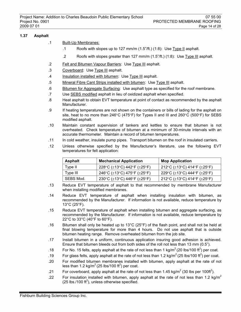
Project Name: Addition to Charles Beaudoin Public Elementary School 07 55 00 Project No. 0901 PROTECTED MEMBRANE ROOFING 2009 07 01 Page 14 of 28 1.37 Asphalt
.1 Built-Up Membranes: .1 Roofs with slopes up to 127 mm/m (1.5”/ft.) (1:8): Use Type II asphalt.
.2 Roofs with slopes greater than 127 mm/m (1.5”/ft.) (1:8): Use Type III asphalt.
.2 Felt and Bitumen Vapour Barriers: Use Type III asphalt.
.3 Coverboard: Use Type III asphalt.
.4 Insulation installed with bitumen: Use Type III asphalt.
.5 Mineral Fibre Cant Strips installed with bitumen: Use Type III asphalt.
.6 Bitumen for Aggregate Surfacing: Use asphalt type as specified for the roof membrane.
.7 Use SEBS modified asphalt in lieu of oxidized asphalt when specified.
.8 Heat asphalt to obtain EVT temperature at point of contact as recommended by the asphalt Manufacturer.
.9 If heating temperatures are not shown on the containers or bills of lading for the asphalt on site, heat to no more than 246°C (475°F) for Types II and III and 260°C (500°F) for SEBS modified asphalt.
.10 Maintain constant supervision of tankers and kettles to ensure that bitumen is not overheated. Check temperature of bitumen at a minimum of 30-minute intervals with an accurate thermometer. Maintain a record of bitumen temperatures.
.11 In cold weather, insulate pump pipes. Transport bitumen on the roof in insulated carriers.
.12 Unless otherwise specified by the Manufacturer’s literature, use the following EVT temperatures for felt application:
Asphalt Mechanical Application Mop Application Type II 228°C (±13°C) 442°F (±25°F) 212°C (±13°C) 414°F (±25°F) Type III 246°C (±13°C) 475°F (±25°F) 229°C (±13°C) 444°F (±25°F) SEBS Mod. 230°C (±13°C) 446°F (±25°F) 212°C (±13°C) 414°F (±25°F)
.13 Reduce EVT temperature of asphalt to that recommended by membrane Manufacturer when installing modified membranes.
.14 Reduce EVT temperature of asphalt when installing insulation with bitumen, as recommended by the Manufacturer. If information is not available, reduce temperature by 13°C (25°F).
.15 Reduce EVT temperature of asphalt when installing bitumen and aggregate surfacing, as recommended by the Manufacturer. If information is not available, reduce temperature by 22°C to 33°C (40°F to 60°F).
.16 Bitumen shall only be heated up to 13°C (25°F) of the flash point, and shall not be held at final blowing temperature for more than 4 hours. Do not use asphalt that is outside bitumen heating range. Remove overheated bitumen from the job site.
.17 Install bitumen in a uniform, continuous application insuring good adhesion is achieved. Ensure that bitumen bleeds out from both sides of the roll not less than 13 mm (0.5”).
.18 For No. 15 felts, apply asphalt at the rate of not less than 1 kg/m2 (20 lbs/100 ft2) per coat.
.19 For glass felts, apply asphalt at the rate of not less than 1.2 kg/m2 (25 lbs/100 ft2) per coat.
.20 For modified bitumen membranes installed with bitumen, apply asphalt at the rate of not less than 1.2 kg/m2 (25 lbs/100 ft2) per coat.
.21 For coverboard, apply asphalt at the rate of not less than 1.45 kg/m2 (30 lbs per 100ft2).
.22 For insulation installed with bitumen, apply asphalt at the rate of not less than 1.2 kg/m2 (25 lbs./100 ft2), unless otherwise specified.
Fishburn Building Sciences Group Inc.
Project Name: Addition to Charles Beaudoin Public Elementary School 07 55 00 Project No. 0901 PROTECTED MEMBRANE ROOFING 2009 07 01 Page 15 of 28
.23 For mineral fibre cant strips installed with bitumen, apply asphalt at the rate of not less than 1.45 kg/m2 (30 lbs per 100ft2).
1.38 Drains and Drainage Plane
Inspect surfaces and ensure that: .1 Roof deck is level or sloped to drains in conforming to design intent. .2 Roof drains are set at a level to drain and are connected or capped. .3 Inspect roof drains to ensure they are open and working properly.
1.39 Hidden Services
.1 Investigate the location of all known hidden services by reviewing interior conditions, plans, specifications and drawings for the building, any subsequent alterations, completion of cut tests and interviewing those involved in the construction and maintenance of building services. These services include but are not limited to mechanical, electrical, cable, communication, computer, security or roof assembly. Ensure all services are located and will be protected from damage under the Contract.
1.40 Equipment
.1 Inspect equipment affected by the work, including but not limited to roof top equipment, curbs, drains and plumbing, mechanical, electrical and services, to ensure they are in good repair. Record any damage and advise the Consultant.
.2 During roofing, ensure that all mechanical equipment is properly supported.
.3 Notify Owner and/or Consultant of any equipment which is damaged prior to the commencement of work.
1.41 Advise Consultant
.1 Advise the Consultant of any unusual circumstances affecting the work. Notify the Consultant of any defective or malfunctioning equipment or drains found plugged, damaged or leaking. Do not commence work until defects and incorrect levels have been verified and rectified.
1.42 Proceeding with Work
.1 The commencement of work is proof that the Contractor has accepted surfaces as satisfactory and accepts responsibility for appearance and performance of completed work.
.2 Be responsible and repair and pay all cost and fees required to rectify damage caused by work of this Contract with materials and finish to match the original.
1.43 Services
.1 Contractor to verify location of services prior to commencement of work. Notify Owner/Consultant of any unusual conditions.
.2 The Contractor and their employees must hold valid certificates for the work undertaken.
PART 2 – PRODUCTS
2.1 General
.1 All standards, regulations and specifications listed herein are considered to be the latest available edition.
Fishburn Building Sciences Group Inc.
Project Name: Addition to Charles Beaudoin Public Elementary School 07 55 00 Project No. 0901 PROTECTED MEMBRANE ROOFING 2009 07 01 Page 16 of 28
.2 Compatibility between materials is essential. Use only materials that are known to be compatible when incorporated in a complete assembly.
2.2 Primers
.1 Asphalt Primer: Conforming to CGSB 37-GP-9Ma-83.
.2 Modified Bitumen Primer: For modified roofing, as recommended by the membrane Manufacturer to CGSB 37-GP-9Ma-83.
2.3 Thermal Barrier, Sheathing Board, Adhesive and Tapes
.1 Water Resistant Gypsum Core with Glass Mat Facers: Fibreglass-faced gypsum board. Minimum 12.7 mm (0.5”) thickness, or 15.9 mm (0.625”) thickness where FM approval is specified and/or shown on the drawings. Dens-Deck or Dens-Deck Prime by Georgia-Pacific or equal.
2.4 Asphalt, Bitumen and Felts
.1 Base Sheet: Flashing SBS modified bitumen reinforced with 180g/m2 polyester to meet CGSB 37-GP-56M. Type 2, Class A, Grade 2 and Type II, Class C, Grade 2 (mop and torch grade).
.2 Cap Sheet: SBS modified bitumen 250g/m2 polyester reinforced. Type 2, Class G, Grade 2. Colour light grey. (Torch grade).
.3 Inorganic Felts: Type IV saturated glass fibre roofing felts to D2178-97A.05 and CSA A123.17.
.4 Organic Felts: No. 15 asphalt saturated roof felt, perforated conforming to CSA Standard A123.3 M1979.
.5 Bitumen: Roofing asphalt conforming to CSA Standard A123.4M 1979.
.6 Rubberized Asphalt Primer: Modified asphalt primer as specified by the Manufacturer of membrane is being installed.
.7 Self-Adhering Membrane and Primer: Minimum 160 gm/m2 non-woven polyethylene reinforced SBS polyester modified base sheet to CGSB 37-GP-56M-85, Type 2, Class P, Grade 2. Provide primer and sealant as supplied by the Manufacturer of the Self-adhering membrane to make a complete installation.
2.5 Miscellaneous Roofing Sealants and Adhesives
.1 One Component Rubberized Mastic: Polybitume by Henry, Sopramastic 200 by Soprema, MBR flashing cement by Johns Mannville or approved equal to CAN/CGSB 37.5M.
.2 Two Component Modified Sealant: Cold Gold flashing cement by IKO Industries or approved equal.
.3 Box Filler: One part pourable sealer by Chemlink Inc. and M1 Structural Sealant Primer.
2.6 Insulations
.1 Roof Insulation: 100 mm (4”) for roof and 38 mm (1.5”) for flashings unless otherwise specified as shown on the drawings, Type IV extruded polystyrene to CAN/ULC S701. Roofmate by DOW or Foamular 350 by Owens Corning. Insulation for roof to be underscored as specified elsewhere this Section.
.2 Mineral Fibre Cants: Mineral aggregate, unless otherwise specified or shown 150 mm x 150 mm (6” x 6”). Roxul or approved equal.
.3 Batt Insulation: Mineral wool (AFB) acoustical fire batt by Roxul or approved equal.
Fishburn Building Sciences Group Inc.
Project Name: Addition to Charles Beaudoin Public Elementary School 07 55 00 Project No. 0901 PROTECTED MEMBRANE ROOFING 2009 07 01 Page 17 of 28
.4 Tapered Insulation: Type IV polystyrene conforming to CAN/ULC A701. Dow Stryofoam SM or equal. Refer to details for size and thickness.
.5 Spray-In-Place Urethane: As specified and/or shown on the Drawings, conforming to CAN/ULC-S705.1-01 and CAN/ULC-S705.2-98.
2.7 Miscellaneous Fixtures
.1 Vent Stack Flashing: 450 mm (18”) G-CVTB-RI8 copper vent stack as shown on drawings by Altra Metal Specialties Inc. or approved equal (supply by Sections 22 00 00 and 23 00 00).
.2 Sanitary Vent Stack Flashings: Size as specified and/or shown on the Drawings, by Altra Metal Specialties Inc. or approved equal: Aluminum, tapered body w/ tapered rubber gasket collar, 450 mm (18”) G-AVTB-R12 (supply by Sections 22 00 00 and 23 00 00);
.3 Metal Sleeves: Copper 450 mm (18”) G-ASB-18 type and size as shown on the drawings by Altra Metal Specialties Inc. or approved equal (supply by Sections 22 00 00 and 23 00 00).
.4 Roof Drains: Supply and install by Division 15.
.5 Overflow Scuppers: Size and materials as specified or shown, fabricated from (454 gms (16 oz.) copper or 26-gauge stainless steel with minimum 125 mm (5”) roof flange and gravel guard. Make all seams continuous and watertight by soldering.
.6 Aggregate: Crushed stone, graded 25 mm (1”) clear, water-washed and free from fines.
.7 Concrete Pavers and Splash Pads: Unless otherwise specified or shown, 600 mm square (24” x 24”) x 38 mm (1.5”) wire reinforcement pre-cast concrete. To CSA A231.1-1972 6% air entrained to 30 MPA.
.8 Water Permeable Fabric: “Fabrene AMB” manufactured by Dupont Canada.
.9 Flexible Conduit Sleeve: Size to suit size and number of conduits: Aluminum, 450 mm (18”) G-ACS; by Altra Metal Specialties Inc. or approved equal (supply by Section 26 00 00).
.10 Exhaust Vent: Aluminum exhaust vent flashing by Thaler Metal Industries Inc. or approved equal. Model EVF-1 with slotted collar for dryer exhaust and Model EVF-2 with perforated collar for washroom exhaust. Size as specified and/or shown on the Drawings (supply by Sections 22 00 00 and 23 00 00).
.11 Pre-manufactured Metal Roof Equipment Curbs: Fabricate from 18 gauge galvanized steel, 450 mm (18”) high, pre-insulated, fully welded construction, with monolithic and smooth top surface. Size to suit equipment (supply by Sections 22 00 00 and 23 00 00).
.12 Pipe Supports: Wood Pipe Supports: For pipes up to 100 mm (4”), fabricate from pressure treated wood blocking on concrete pavers as specified and/or shown on the Drawings. Height to suit pipeline height (supply by Sections 22 00 00 and 23 00 00).
.13 Concrete Pavers: 600 mm x 600 mm x 38 mm (2’-0” x 2’-0” x 1.5”), unless otherwise specified and/or shown on the Drawings, to CSA A231.1-99 (R2003) with 6%-8% air entrainment, 30 MPa, by Brooklin Concrete Products or approved equal.
.14 Mechanical and Electrical Services: Custom fabricated box to Section 07 63 00 supplied and installed by Roofing Contractor.
2.8 Fasteners
.1 Obtain Consultant and Owner’s approval when using hammer drills since drilling hours may be restricted.
Fishburn Building Sciences Group Inc.
Project Name: Addition to Charles Beaudoin Public Elementary School 07 55 00 Project No. 0901 PROTECTED MEMBRANE ROOFING 2009 07 01 Page 18 of 28
.2 All fasteners for steel, wood, concrete and specialty decks must meet factory mutual approvals.
.3 Use galvanized, copper, aluminum or stainless nails or screws as most compatible with materials being employed. Screws shall be minimum 38 mm (1.5”) #10 cadmium plated hex head with neoprene and steel washers by Atlas Bolt or approved equal. Rawl lead shields as required for anchoring. Use fasteners as most generally suitable to Consultant’s approval. Nails and caps to be hot dipped galvanized or mechanically galvanized to CSA G164-M. Supply by Lexcor (1-800-268-2889) or AMA Roof Supplies (1-877-594-6071) or approved equal.
.4 General Fasteners: No. 10 ardox nails of length to penetrate bases minimum 13 mm (0.5”). Horizontal Membrane Fasteners: Use 50 mm ardox (2”) nails with minimum 25 mm (1”) solid caps for securing membrane to insulation stops. Nails and caps to be hot dipped galvanized or mechanically galvanized to CSA G164-M. Supply by Lexcor (1-800-268-2889) or AMA Roof Supplies (1-877-594-6071) or approved equal.
.5 All nails to meet CSA B111-1974 (R2003).
.6 All tapping and driving screws to meet ASTM B18.6.4 – 1999.
.7 All wood screws to meet ASTM B18.6.1 – 1981.
.8 All galvanizing to meet ASTM A153/A153M-05 and CAN/CSA-G164-M92.
.9 Pressure Treated Wood: When pressure treated wood is specified, use minimum No. 304 stainless steel fasteners.
.10 All fasteners for decks must meet Factory Mutual approvals.
.11 All fasteners, size and spacing to meet the most stringent requirements of this Section, the Drawings, the Ontario Building Code or Factory Mutual requirements.
.12 Thermal Barrier Fasteners: Factory Mutual approved, corrosion resistant, anti-back out screws: Dekfast No. 12 Phillips Head Fastener with IFC/PH 70x70 Insulation Plate, by SFS intec, or approved equal. Fasteners spaced to achieve minimum pull out to meet FM 1 - 75 wind uplift approval. Of sufficient length to penetrate top flute of deck 19 mm (0.75”).
.13 Vertical Flashing Fasteners: For Wood: No. 10 hot dip galvanized spiral nails. For Metal: Powers No. 12 “Deck Screws” with “Perma-Seal” coating. For Concrete, Brick or Masonry: Perma-Grip (Tru-Fast) “Tap-Grip” concrete screw with “Tru-Kote” coating, Powers “Tapper” concrete screw with “Perma-Seal” coating, Powers “Roofing Spike” with “Perma-Seal” coating, or Powers “Zamac Nailin”. All fasteners to be 50 mm (2”) length with 25 mm (1”) hot dipped galvanized solid caps.
.14 Metal to Wood: Where exposed fasteners are specified or shown, use No. 10 cadmium plated, pre-finished hex head screws with neoprene and steel washers by Atlas Bolt or approved equal, of sufficient length to penetrate the base minimum 32 mm (1.25”). Minimum length 38 mm (1.5”). Colour of screw head to match colour of flashing. Provide touch-up paint as required to coat all exposed surfaces of screws damaged during the driving process. Alternatively, use screws with colour match nylon caps where shown or approved by the Consultant.
.15 Pull Out Tests: The type of fastener may be subject to results of pull out tests. When security of fasteners appears to be in doubt, in consultation with the Consultant and fastener supplier, provide pull out tests at a minimum of five locations for each type of material and fastener being employed. Minimum pull out resistance of each fastener shall be 45 kg. (100 lb.). Submit results to Consultant and act on Manufacturer’s written recommendations on the type, length and spacing of fasteners to hold the item being secured permanently in place, and to prevent warping, deflection or displacement of materials against all wind and weather conditions. Submit summary of findings to the Consultant for review before proceeding.
Fishburn Building Sciences Group Inc.
Project Name: Addition to Charles Beaudoin Public Elementary School 07 55 00 Project No. 0901 PROTECTED MEMBRANE ROOFING 2009 07 01 Page 19 of 28 PART 3 - EXECUTION
3.1 General
.1 Execute Work in accordance with the Specification, Drawings and Details.
.2 Anchor roofing to requirements of Insurance Underwriter and authorities having jurisdiction.
.3 Do not install any roofing when temperatures, including wind chill, is below -26°C (-15°F).
.4 Lay out Work to avoid working over newly installed felts. If any foreign material is inadvertently incorporated into the membrane, remove the material immediately and repair to restore membrane to its original integrity. Repair with 4-plies felt or 2-ply modified bitumen base and cap sheet to match the original membrane type. All repair felts or sheets shall lap over the repair area and each previous ply 150 mm (6”) in each direction. Broom all repair areas into place to ensure positive contact.
.5 Maintain equipment in good working order to ensure control of roofing operations and protection of Work. Types of roofing equipment and laying techniques to be employed are to meet the approval of the Consultant.
.6 Before bitumen has set, avoid foot traffic or prolonged point loading on membrane that will result in displacement of bitumen between plies of felt or membrane.
.7 Do not penetrate roof deck with any fastening devices that would do damage or impair the function of the roof assembly.
3.2 Daily Operations
.24 Unless otherwise specified, complete entire roofing operation up to the line of termination of each day’s work to meet the design intent in order to safeguard and protect the Work and building from damage and weather.
.25 Do not leave roofing felts exposed overnight; coat the surface of the last ply of felt with a squeegee coat of Type II asphalt immediately following installation of the felt.
.26 Install base sheet and flashing the same work period.
3.3 Primer
.1 Prime masonry and concrete surface which will be in direct contact with asphalt at the rate of 0.15 L/m2 (0.25 gal./100 ft2). Ensure that surfaces are tack-free before proceeding.
.2 Limit quantity of primer at deck openings and points of termination to prevent bleedthrough to the building interior.
.3 Broom primer into surface.
.4 Re-prime all surfaces that become contaminated with dust or become marred due to their exposure to roof traffic or weather.
3.4 Thermal Barrier
.1 Install thermal barrier on steel decks as specified and/or shown on the Drawings.
.2 Install in accordance with Manufacturer’s and Factory Mutual requirements. Commence installation at low points and/or at the drains. Shim board solid at areas of deck deflections so that slope of finished surface is maintained.
.3 Butt boards with moderate contact and with edges bearing minimum of 38 mm (1.5") on the top flange of the deck. Stagger end joints minimum 600 mm (2'). Do not force into place.
.4 Use maximum size sheets to reduce the number of joints.
.5 Cut neatly at projections and points of termination.
.6 Replace all broken, damaged or misfit boards as Work progresses. Lay only sufficient boards as can be covered by membrane roofing in the same work period.
Fishburn Building Sciences Group Inc.
Project Name: Addition to Charles Beaudoin Public Elementary School 07 55 00 Project No. 0901 PROTECTED MEMBRANE ROOFING 2009 07 01 Page 20 of 28 3.5 Thermal Barrier Mechanical Fastening on Steel and Decks
.1 Unless otherwise specified or shown on the Drawings, use mechanical fasteners to secure the thermal barrier to wood, steel or acoustic steel decks.
.2 Conform to Factory Mutual requirements for spacing and number of fasteners required to provide FM 1 - 75 wind uplift rating, unless otherwise specified. Submit Engineered Shop Drawings showing layout thermal barrier boards and the spacing and number of fasteners for the field, perimeter and corners of the roof.
.3 Inspect the underside of the deck to ensure fasteners will not damage electrical and mechanical services.
.4 Size fasteners to penetrate steel deck 19 mm (0.75”).
.5 Size fasteners to penetrate wood deck 25 mm (1”).
.6 Advise Consultant of any unusual circumstances affecting the Work. Correct all damage caused by Work to match existing materials and finish.
.7 Secure boards with specified fasteners and plates.
.8 On steel decks, ensure that mechanical fasteners engage the top flange of the deck. A chalk line guide is recommended to ensure fasteners engage the top flange.
.9 Workmen shall be properly trained to understand the signs of mechanical fastener full engagement.
.10 Install an additional fastener at all "T" joints.
.11 Prime metal plates that will be covered with bitumen roofing. Ensure primer is tack-free before proceeding.
.12 Complete random Pull-Out Tests to determine average Pull-Out Resistance. Adjust fastener density as per Factory Mutual Loss Prevention Bulletin 1-29 if required.
3.6 Air Seals
.1 Unless otherwise specified in Section 07 50 16, provide air seals at the roof perimeter and roof openings as shown on the Drawings.
3.7 Tapered Insulation
.1 Where shown on the drawings install tapered fibreboard insulation to be used as a back slope or crickets installed in a continuous coat of Type II asphalt. Make field adjustments as required to ensure design intent and specified slope is achieved.
3.8 Cants Strips
.1 Install mineral fibre cants in full coat of Type II asphalt. Underlay cant strips with 2 ply of No. 15 felt or 1 ply 95g/m2 base sheet installed with a continuous coat of Type II asphalt unless otherwise shown on the drawings.
3.9 Cants and Insulation Crickets Underlay
.1 Install mineral fibre cants and tapered insulation crickets underlaid with 2-ply No. 15 asphalt felt set in a solid coat of Type III asphalt unless otherwise shown on the drawings.
3.10 Installation of Glass Felt Membrane
.1 Ensure all substrate surfaces are dried by artificial or natural means before installation of membrane.
.2 Membrane is to be constructed from 3-plies if Type IV glass and 1-ply if 250gm cap sheet.
.3 Felt overlap each sheet of felt 620 mm (24.75”), overlap end laps 225 mm (9”) minimum.
.4 Offset end joints of felt by minimum 1200 mm (4’-0”).
Fishburn Building Sciences Group Inc.
Project Name: Addition to Charles Beaudoin Public Elementary School 07 55 00 Project No. 0901 PROTECTED MEMBRANE ROOFING 2009 07 01 Page 21 of 28
.5 Underlay glass felt at all points of termination including opening in the roof with 1-ply of No. 15 felt 300 mm (12”) wide, laid solid with bitumen.
.6 Roll each ply of felt in uniform coat of bitumen.
.7 Broom felts in place to obtain complete embedment.
.8 Install felts smooth, free of wrinkles, air pockets, fishmouths and tears.
.9 If fishmouths in membrane inadvertently occur, cut fishmouth and work felt into bitumen immediately while bitumen is still hot. Repair all fishmouths with two additional plies of glass felts and bitumen extending a minimum of 150 mm (6”) in each direction over the fishmouth and previous ply of felt.
.10 Do not gang roll felts during application. Keep rolls a minimum of 2.0 metres (6’-0”) apart during application. Protect new membrane from wheel and foot traffic until bitumen is set.
.11 Install felts commencing at roof or scupper drains in continuous application of felt to the top of the cant strips.
.12 Install felt so that water flows with or overlap joints.
.13 Ensure that felts at inside and outside corners fits tight to all verticals without gaps. Cut felt at all changes in plane to ensure a solid bond to the sub-straights is achieved.
.14 Seal all felts installed at the cant strips with a continuous coat of asphalt as work progresses.
.15 Seal the felts at the top of cant strips or where they terminate on a vertical surface with rubberized mastic.
.16 Except where construction changes direction and the membrane follows, avoid coinciding end joints that would interfere with water flow. Install an additional 2-ply of fibreglass felt laid solid with bitumen to reinforce end joints where the membrane changes direction.
.17 Providing roof levels have been verified and corrected and the cap sheet is scheduled to be installed during the same work period, leave surface of bitumen membrane uncoated.
.18 If the construction schedule will not allow cap sheet membrane and base sheet and cap sheet flashings to be installed in the same work period, coat the surface of the felts with a squeegee coat of asphalt. Apply at a rate of approximately 1.2kg/m2 (25lb/100ft2).
.19 Overnight Tie-in: Protect all unfinished work and provide temporary weatherproof seals at points of termination of each day’s work. The temporary seals are to be removed and trimmed back to as to allow for tight fitting joints before proceeding with new work.
3.11 Copper Roof Drains
.1 Co-ordinate the installation of roof drains as supplied by Sections 22 00 00 and 23 00 00.
.2 Verify that the drain has been set at the low point and at a location that will prevent ponding of water on the surface of the roof of the membrane after the roof drain has been installed.
.3 Coat all flanges to receive roofing with primer and ensure primer is dry to touch before proceeding.
.4 Coat drain flanges to receive membrane with modified sealant and install 1-ply if No. 15 felt continuing from inside face to 300 mm (12”) past the roof flange.
.5 Install 3-ply felt and cap sheet continuing over flange and neatly trim membrane at the drain opening. Seal cut ends with rubberized mastic.
.6 Set clamp ring in continuous coat of rubberized mastic. Secure clamp ring and integral screen as dictated by drain design immediately after membrane installation.
.7 Tighten bolts to ensure a permanent watertight compression seal. Torque bolts to 10.0ft/lb pressure with torque wrench.
Fishburn Building Sciences Group Inc.
.8 Install control flow devises if specified and install ballast screen securely in place.
Project Name: Addition to Charles Beaudoin Public Elementary School 07 55 00 Project No. 0901 PROTECTED MEMBRANE ROOFING 2009 07 01 Page 22 of 28 3.12 Custom Fabricated Scuppers
.1 Inspect the proposed locations, length and size of the scuppers to ensure their installation will not conflict with adjacent construction, entrances to buildings window at a lower level; electrical or mechanical services mounted on the walls before proceeding with their installation. Adjust locations to ensure design intent is achieved.
.2 Provide shop drawings and mock-up of scupper for review as specified in 1.8 and 1.10 of this Section.
.3 Cut neat hole in felt membrane and base sheet flashings 25 mm (1”) larger than the size of the scupper.
.4 Restore air, moisture and thermal protection of the building and wall finishes caused by work to match existing materials and finish.
.5 Install base sheet flashings through the scupper opening to ensure the opening is made watertight prior to the scuppers installation.
.6 Coat all flanges to receive roofing with primer and ensure primer is dry to the touch before proceeding.
.7 Install scupper on top of completed felt membrane and base sheet flashings true to plumb, level and true to line. Secure flanges 9 mm (0.75”) from the outer edge of the roof flange at minimum three locations each side.
.8 Set flange for scupper in a solid coat of rubberized mastic.
.9 Flash scupper with a ply of base sheet flashing, commencing 25 mm (1”) from the scupper opening, continuing past the flange 150 mm (6”).
.10 Continue cap sheet to within 13 mm (0.5”) of the scupper openings.
.11 Seal the membrane termination point at the scupper with rubberized mastic.
.12 Cut neat hole in water permeable fabric to size if scupper opening and install a gravel guard screen to hold fabric in place.
3.13 Plumbing Vents, Stacks and Sleeves
.1 Co-ordinate work of this Section with Division 23 00 00 and 26 00 00 and allow for return to site to complete work not completed during roofing as per 3.13.16.
.2 Confirm the location and size of all roof openings for mechanical and electrical services that penetrate the roof before proceeding with roof operations.
.3 At roof penetration provide air, moisture and thermal protection.
.4 Protect flashing not covered by roofing with metal shield to prevent damage and bitumen contaminations during roofing operations. Remove shields following flashing operations.
.5 Prime top and bottom of metal sleeve to be covered with roofing. Primer to be dry to the touch before commencing with roofing operation.
.6 Install sleeve flashings on top of complete felt membrane prior to installing modified membrane cap sheet.
.7 Install flanges on solid coat of rubberized mastic.
.8 Flash all flanges with 3-ply of Type IV felt and bitumen. Install first ply 50 mm (2”), second ply and third ply 19 mm (0.75”) from the metal upturn. Extend first ply 150 mm (6”), second ply 225 mm (9”) and third ply 300 mm (12”) beyond the flange.
.9 Coat finished surface of membrane flashings with bitumen immediately upon installation.
.10 Install modified cap sheet from field of roof to within 13 mm (0.5”) from metal upturn and trim neatly.
.11 Seal junction of metal and membrane flashing with rubberized mastic and cover with matching granules as work progresses.
Fishburn Building Sciences Group Inc.
Project Name: Addition to Charles Beaudoin Public Elementary School 07 55 00 Project No. 0901 PROTECTED MEMBRANE ROOFING 2009 07 01 Page 23 of 28
.12 Insulate sleeves with two-component polyurethane foam mineral wool insulation as shown on the drawings. Seal openings between flashings and pipes with polyurethane sealant sloped to shed water.
.13 At soil pipe cut off excess pipe or have height of pipes adjusted by division 01 50 00 to ensure stack extends above flashings by approximately 38 mm (1.5”). Install vandal-proof caps as shown on the drawings.
.14 On stacks, install rain collars to match materials to which it is installed. Solder rain collars up to 22-gauge material and weld 22-gauge or heavier; otherwise caulk rain collars in place with polyurethane sealant if so shown on the drawings.
.15 Clean and paint all weld joints with one coat of primer and one coat of exterior oil base paint, colour to match stack as close as practical.
.16 If stacks or pipes are not installed with roofing operation return to the site to complete specified installation following the work of other trades.
.17 Remove and replace all damaged flashings and poorly fitting collars.
.18 Clean exposed surfaces free of bitumen before leaving site. Paint over all bitumen stains with paint to match flashing colour.
3.14 Build-up Low Points
.1 Prior to the application of modified cap sheet at low points where the roof will pond water, provide squeegee coat of asphalt and a base sheet to build up low areas. Repeat operation with additional layers of Type III asphalt and base sheet until area of pond is eliminated. Each coat of asphalt and ply of base sheet is to extend beyond the preceding ply by 225 mm (9”). Maximum thickness at any one point is 19 mm (0.75”), or 4 layers of membrane.
.2 At low points which pond more than 19 mm (0.75”) of water, build-up area to correct slope with slope correcting fill. Provide primer, base sheets and sloping fill to provide a completed installation in accordance with Fill Manufacturer’s recommendations.
.3 Provide a roof plan showing the extent, thickness and slope of all filled areas to the Consultant for review before proceeding with finished membrane applications as specified in Part 1, General 1.11.
3.15 Modified Membrane Flashings and Cap Sheet Installation
General
.1 Provide a mock-up of modified flashing and cap sheet installation for the Consultant and Manufacturers review before commencing with flashing and cap sheet operations.
.2 In consultation with the membrane Manufacturer, inspect and seal all substitutes to minimize fire hazards.
.3 Install base sheet underlay where shown on the drawings and/or required to minimize fire hazards at all parapets, wall, joints and curbs.
.4 Prior to installation lay out all sheets to allow them to relax (condition) a minimum of 30 minutes. After conditioning, inspect sheets for alignment and inspect cap sheet for granular colour and embedment. Re-roll all sheets immediately before installing.
.5 When temperatures are below 4.4°C (40°F), store rolls and lay out rolls in heated storage. Install before temperature fallback of the sheet occurs. Torch Application
.6 Before proceeding with torch operations, review the type of torches and torching procedures with the membrane manufacturer on site.
Fishburn Building Sciences Group Inc.
Project Name: Addition to Charles Beaudoin Public Elementary School 07 55 00 Project No. 0901 PROTECTED MEMBRANE ROOFING 2009 07 01 Page 24 of 28
.7 Soften surfaces to be bonded simultaneously by means of a propane torch. Obtain continuous flow of bitumen without degradation of the reinforcing or surface finish.
.8 Roll membrane into the bitumen while hot to ensure total bonding of surfaces is achieved. Install membrane true to line, free of buckles, air pockets, fishmouths and voids.
.9 Provide a continuous flow of bitumen beyond end and side lap joints of no more than 6 mm (0.25").
.10 Cover all bleedout runs on cap sheet that exceed more than 6 mm (0.25") with matching granules continuous with application. Mop Application
.11 Install membrane into a continuous layer of bitumen installed at a rate of NOT less than 1.22 kg/m2 (25 lbs/100 ft2). Keep the mop no further than 2 m (6’-0”) ahead of the roll
.12 Provide a continuous flow of bitumen beyond end and side lap joints but no more than 13 mm (0.5”).
.13 Roll membrane into the bitumen while hot to ensure total bonding of surfaces is achieved. Install membrane true to line, free of wrinkles, air pockets, fishmouths and voids.
.14 Cover all bleedout runs that exceed 13 mm (0.5”) on cap sheet with matching granules continuously with application. Cap Sheet
.15 .Do not work over membrane roofing until membrane has cooled to allow for foot and equipment traffic without doing damage or displacing bitumen.
.16 Do not install cap sheet until base sheet flashings are installed.
.17 Cover bitumen membrane with 1-ply of modified cap sheet torched in place.
.18 Cap sheet is to be installed in full lengths unless otherwise specified or required.
.19 Lay all membrane starting at low points to ensure that seams do not face water flow. Commence application with first ply centered over the roof drains.
.20 At end laps and other locations of cap sheet to be overlapped, embed granular with torch and trowel to ensure proper bonding of overlapping sheets is achieved. Offset all end laps between plies minimum 1200 mm (4’-0”).
.21 Overlap all end laps minimum 150 mm (6") and side laps 75 mm (3").
.22 Cut off corners at 45° at end laps to be covered by the next roll prior to installation of following sheet.
.23 Ensure that a watertight seal is achieved at all overlaps and points of termination.
.24 Carry cap sheet to the top of all cant strips and up all vertical surfaces to the points shown on the drawings. If cap sheet flashings are not to be installed in the same work period, seal membrane at the top of cants with sealant to provide a temporary seal immediately upon application of the membrane.
.25 Install cap sheet within 13 mm (0.5") of upturns at metal sleeves built into the roof membrane.
.26 Seal all points of termination with sealant and granules. Press granules in place with sponge to ensure positive embedment.
.27 Base sheet and Cap Sheet Flashings
.28 At parapet, wall, curb, expansion joint, etc. install 1-ply modified base sheet and 1-ply modified cap sheet torched in place.
.29 All flashings to be cut across the roll in 1 m (39") sections. Cut off corners at end laps to be covered by next flashings piece.
.30 Provide chalk lines and install all membrane true to line.
Fishburn Building Sciences Group Inc.
Project Name: Addition to Charles Beaudoin Public Elementary School 07 55 00 Project No. 0901 PROTECTED MEMBRANE ROOFING 2009 07 01 Page 25 of 28
.31 Install gusset reinforcement pieces at all corner locations minimum 75 mm (3") wide at inside and outside corners (base sheet only).
.32 Carry base sheet onto opposite plane minimum 150 mm (6"). Reverse plane between base and cap sheet flashings.
.33 Trim final ply of cap sheet flashings flush with corner. Use a hot knife to ensure a sharp cut, true to line. Work corner to ensure a positive bond is achieved.
.34 Commence flashings from the low points and overlap all side laps minimum 75 mm (3").
.35 Base sheet flashings to extend 100 mm (4") onto roof surface.
.36 Carry base sheet flashings over the face of the building and over the top of curbs and up vertical surfaces as shown on the drawings.
.37 Cap sheet flashings to extend 150 mm (6") onto roof surface and terminate at points shown on the drawings.
.38 Offset cap sheet membrane side laps and cap sheet flashing side laps by approximately 50%.
.39 Complete work to ensure that a watertight seal at all overlaps and all points of termination are achieved.
.40 Secure flashings at 225 mm (9") o.c. at walls, eaves and parapets as shown on drawings with nails or screws with 25 mm (1") caps.
.41 Seal the top of all flashings on verticals with coat of liquid membrane sealed to obliterate the top edge of the flashings and fasteners.
3.16 Insulation
.1 Do not apply insulation until bitumen membrane and flashings are complete and the roofs drainage has been verified.
.2 Carefully re-inspect surfaces and repair all defects in the membrane and flashings that were not otherwise corrected during the initial installation.
.3 Insulation is to be loose laid over modified bitumen cap sheet in one layer of specified thickness.
.4 Insulation is to cover entire roof area including verticals as shown on the details.
.5 Provide shop drawings and in conformance with drawings, underscore new insulation over entire roof area. Install 13 mm x 13 mm (0.5” x 0.5”) channels around board perimeter, one down the centre of the board running the long direction of the board and two access the short direction of the board.
.6 Back-cut insulation as required to allow insulation to conform and fit to irregular surfaces without bridging.
.7 Cut insulation to fit neatly at projections and points of termination.
.8 Lay insulation in parallel courses. Stagger end joints. Lay board with moderate contact without forcing into place.
3.17 Tapered Insulation at Roof Drains
.1 Except at overflow scupper locations install tapered polystyrene insulation to form a sump 1200 mm (4’-0”) each side of roof drain and scuppers. Insulation to be tapered from base insulation thickness to 38 mm (1.5") at the drain or scupper.
.2 At all locations of tapered insulation provide shop drawings from tapered insulation Manufacturer for Consultant’s review prior to installation as specified in 1.24 of this Section.
3.18 Water Permeable Fabric
Fishburn Building Sciences Group Inc.
Project Name: Addition to Charles Beaudoin Public Elementary School 07 55 00 Project No. 0901 PROTECTED MEMBRANE ROOFING 2009 07 01 Page 26 of 28
.1 Cover all insulation with water permeable fabric. Extend where shown and overlap all edges 300 mm (12”). Carry over or turn up all vertical flashings and secure to wood nailers with galvanized nails with 25 mm (1”) metal caps at 300 mm (12”) o.c. Cut neat openings for sleeves and drains and trim to base of drain. Minimum sheet size at any point shall be 1800 mm (6’-0”) square.
3.19 Stone Ballast
.1 Do not install stone ballast until membrane roofing, flashings, insulation and water permeable fabric is complete and has been inspected.
.2 Install stone ballast at a rate of 58.6kg/m2 (1200lb/100sq.ft). Increase weight of stone ballast to 83 kg/m2 (17lbs/ft2) 2 metres (6’-6”) each side of drain and 101 kg/m2 (22lbs/ft2) 1200 mm (4’-0”) around all perimeters.
.3 Keep aggregate back to allow counter flashings to be installed. Complete operation by returning stone ballast over base of metal flashings for a depth of 50 mm (2”). Rake out, add or remove aggregate to leave a uniform level surface to specified weight requirements.
.4 Maintain roof plan and record of test results on form provided by the Consultant. Verify aggregate weights in two locations each work period. Co-ordinate work and complete test at locations agreed upon with the Consultant while work is in progress.
3.20 Concrete Pavers
.1 Install concrete pavers where shown to requirements of specification and drawings.
.2 Unless otherwise specified or shown on the drawings, install two concrete pavers at the top and bottom of all roof ladders.
.3 Unless otherwise specified or shown on the drawings, install a cluster of four pavers at penthouse doors.
.4 Where pavers are installed, eliminate stone ballast and install paver on a 50 mm (2”) layer of extruded polystyrene insulation underscored top and bottom in both directions at 150 mm (6”) o.c. to allow for venting, underscore channels to measure 6 mm x 6 mm (0.25” x 0.25”). Cut insulation 38 mm (1.5”) smaller on all sides so that paver overhangs and protects insulation from direct sunlight. Build up aggregate at edge of paver to eliminate the gap.
.5 When bolting wood or equipment to pavers, pre-drill holes through paver and install bolt from underside through to top and secure equipment with washers and nuts. Countersink bolt heads into wood. Snug bolts tight.
3.21 Gas Pipe Supports
.1 Co-ordinate work with Division 23 00 00.
.2 Elevate gas line on supports to minimum 300 mm (12”) above final roof (finish) and to clear all expansion and control joints by 25 mm (1”) unless otherwise specified or shown.
.3 Gas line supports to be pre-manufactured metal and pressure treated wood as specified and shown on the drawings.
.4 Secure metal brackets or wood blocking to concrete paver with two 9 mm (0.375”) galvanized iron bolts installed through paver. Insert bolts from bottom and bolt to paver with washer and nut tightened for positive securement. Tighten roller assembly into bracket at desired height and secure in place with lock nuts. Ensure roller assembly is allowed 3 mm (0.125”) minimum spacing and will accommodate movements of pipes due to expansion and contraction.
.5 Install supports at spacing specified in Division 23 00 00.Adjust spacing to safeguard the roof from damage due to excessive spot loading. Maximum loading on any paver to be 244kg/m2 (50lbs/ft2).
Fishburn Building Sciences Group Inc.
Project Name: Addition to Charles Beaudoin Public Elementary School 07 55 00 Project No. 0901 PROTECTED MEMBRANE ROOFING 2009 07 01 Page 27 of 28
.6 Adjust heights to ensure even distribution of gas pipe weights between supports. Increase spacing of supports to prevent deflection of pipes in snow piling areas.
.7 Locate pipe supports over joists, beams or other structural members wherever possible.
3.22 Clean-up
.1 Keep the premises free from accumulation of waste materials or rubbish at all times. Stock piling of debris on the roof will not be permitted.
.2 Leave roof clean of debris and bitumen left by spills and machine tracking.
.3 Leave grounds and building free of debris and bitumen spread by pedestrian traffic where applicable. Rake out excessive piles of aggregate and trim to neat, even surface.
.4 Clean surfaces and penetrations of all contaminants and touch up to the satisfaction of the Owner. Include roof top equipment, curbs, soil stacks, sleeves, gas lines, vents, drains, ladders and walls.
.5 Check drains to ensure they are functional and where required removal of all debris by vacuum.
.6 At the completion of the work remove all rubbish, tools, equipment and surplus materials.
.7 Be responsible to repair and pay all costs and fees required to rectify damage caused by work of the Contract with materials and finish to match original.
3.23 Contractor Quality Control
.1 Contractor’s Quality Control shall be completed in accordance with Section 07 55 00.
3.24 Inspection and Testing
.1 Field review of the work will be completed by Fishburn Building Sciences Group Inc. (Consultant).
.2 Examination of materials' certificates and test reports shall not be construed as relieving the Contractor of his responsibility for proper completion and guarantee of the work in accordance with the Drawings and Specifications.
.3 Notify the Architect/Owner/Consultant and material Manufacturer at least 48 hours before roofing operations commence, and arrange for a site meeting for discussion of procedure. Subsequently, give two working days prior notice for the commencement of each phase of work. Notify of delays and re-starts.
.4 Cooperate with Consultant and afford all facilities necessary to permit full inspection of the work and testing of materials prior to, during their use and during the warranty period. Act immediately on instructions given. Make cut-out for testing purposes when and where required and make good roofing of test areas and of any and all defects of materials and workmanship without additional cost.
.5 Do not conceal or cover any phase of the work until after it has been inspected and approved.
.6 Inspection of the Contract Documents as to extent of work, quality of workmanship and materials, methods, etc. is the responsibility of the Architect.
3.25 Non-Compliance with Inspections and Tests
.1 If the initial inspection and tests required to establish compliance with the Contract Documents indicates non-compliance with the Contract Documents, subsequent tests or re-inspection occasioned by non-compliance shall be performed. The cost of re-inspection and testing will be borne by the Contractor and deducted from the price of the Contract.
.2 The Contractor shall replace or correct defective work not done in accordance with the
Fishburn Building Sciences Group Inc.
Project Name: Addition to Charles Beaudoin Public Elementary School 07 55 00 Project No. 0901 PROTECTED MEMBRANE ROOFING 2009 07 01 Page 28 of 28
Fishburn Building Sciences Group Inc.
Contract. If, in the opinion of the Architect, it is not expedient to correct defective work or work done in accordance with the Contract, the Owner may deduct from the Contract price the difference in value between the work as done and called for by the Contract, the amount of which will be determined by the Architect.
.3 Replace all work that results from inferior products or workmanship.
END OF SECTION 07 55 00
Project Name: Addition to Charles Beaudoin Public Elementary School 07 62 13 Project No. 0901 SHEET METAL FOR BUILT-UP ROOFING 2009 07 01 Page 1 of 7
PART 1 – GENERAL
1.1 General
.1 This section specifies general requirements and procedures for metal flashing and trim related to built-up roofing. Additional requirements may be specified in individual sections of the Specifications.
.2 All conditions of the Contract and Divisions 1 apply to this section.
.3 Coordinate work of this section with related work specified in other sections to ensure construction schedule and protection of finished work is maintained at all times.
1.2 Description of Work
.1 Complete all work as specified in the Summary of Work, Specifications and Drawings.
.2 Work of this section includes the supply and installation of all Sheet Metal Work, including eavestroughs and downspouts as required in the Summary of Work and/or as shown on the Drawings. If pre-manufactured units are not specified, custom-fabricate sleeves, scuppers, and overflow scuppers as specified in the Summary of Work and/or shown on the Drawings.
.3 Work also includes sealing joints in flashings as flashing is being installed, and cutting and sealing new reglet joints and open sheet metal joints at locations shown on the Drawings.
.4 Work “as described” is held to include all incidental items that by implication, good trade practices, or customary usage are required to complete the work, even though they may not be specifically mentioned or shown.
.5 Additional requirements may be specified in individual sections of the Specifications and/or shown on the Drawings.
1.3 Related Work
.1 Roofing Specifications are comprised of the following: 1. Section 07 50 13 – Common Work Results for Roofing 2. Section 07 50 16 – Wood Blocking for Roofing 3. Section 07 50 19 – Sealants for Roofing 4. Section 07 55 00 – Protected Membrane Roofing 5. Section 15000 – Mechanical 6. Section 16000 – Electrical
1.4 References The latest edition of all Standards shall apply if the referenced standards have been superseded.
.1 ASTM A153/A153M-05 Zinc Coating (Hot-Dip) on Iron and Steel Hardware
.2 ASTM A653/A653M-04a: Standard Specification for Steel Sheet, Zinc-Coated (Galvanized) or Zinc-Iron Alloy-Coated (Galvannealed) by the Hot-Dip Process.
.3 ASME B18.6.1 – 1981 Wood Screws (Inch Series) (supercedes CSA B35.4 - 1972)
.4 ASME B18.6.4 – 1999 Thread Forming and Thread Cutting Tapping (supercedes CSA B35.3 - 1969) Screws and Metallic Drive Screws, Inch Series
.5 CGSB 37-GP-9Ma-83 Primer, Asphalt, Unfilled, for Asphalt Roofing, Dampproofing and Waterproofing.
.6 CGSB 37-GP-15M-84 Application of Asphalt Primer for Asphalt Roofing, Dampproofing and Waterproofing.
.7 CSA B111-1974 (R2003) Wire Nails, Spikes and Staples.
.8 CAN/CSA-G164-M92 (R2003) Hot Dip Galvanizing of Irregularly Shaped Articles.
.9 CAN3-G312.1-75 (R2003) Preferred Metric Dimensions for Flat Metal Products.
.10 CRCA (Canadian Roofing Contractor’s Association) Manual.
Fishburn Building Sciences Group Inc.
Project Name: Addition to Charles Beaudoin Public Elementary School 07 62 13 Project No. 0901 SHEET METAL FOR BUILT-UP ROOFING 2009 07 01 Page 2 of 7
.11 SMACNA Architectural Sheet Metal Manual – 2003 Edition.
1.5 Qualifications
.1 Employ only experienced and qualified workers that can provide quality results. Replace all work that results from inferior products or installation.
1.6 Examination
.1 Examine surfaces and report any adverse conditions that could negatively impact the appearance and performance of the work.
1.7 Coordination .1 Coordinate work with related work specified in other sections to ensure that the
construction schedule, water-tightness, and protection of the building and work are maintained at all times.
1.8 Submittals .1 Submit to the Consultant a list of materials intended for use, before they are ordered. .2 Submittals shall be in accordance with Section (07 55 00). .3 Additional requirements may be specified in other sections of the Specifications.
1.9 Shop Drawings, Product Data, Samples and Mock-ups .1 Submit Samples of materials and/or built-in mock-ups for review before proceeding with
the work, including but not limited to the following: .1 Eavestroughs, Downspouts and Water–Conductors; .2 Metal Flashings; and, .3 Custom-Fabricated Scuppers and Overflow Scuppers.
.2 Submittals shall be in accordance with Section (07 55 00).
.3 Additional requirements may be specified in other sections of the Specifications.
1.10 Delivery, Storage & Handling
.1 Provide and maintain safe storage.
.2 Protect materials from damage or removal by wind at all times.
1.11 Environmental Requirements .1 Ensure at all times protection of the building and any unfinished work that can be damaged
by inclement weather. .2 If inclement weather is forecast or appears imminent, postpone work that would risk the
work or building being damaged by moisture. .3 If it becomes apparent that work would threaten the buildings water tightness, the Owner
has the right to stop the work. Any additional expenses due to work stoppage or postponement of the work will be at the Contractor’s expense.
.4 Ensure at all times protection of materials and equipment that are sensitive to damage by moisture.
1.12 Inspection and Testing
.1 Field review of the work will be completed by Fishburn Building Sciences Group Inc. (Consultant).
.2 Examination of materials' certificates and test reports shall not be construed as relieving the Contractor of his responsibility for proper completion and guarantee of the work in accordance with the Drawings and Specifications.
Fishburn Building Sciences Group Inc.
Project Name: Addition to Charles Beaudoin Public Elementary School 07 62 13 Project No. 0901 SHEET METAL FOR BUILT-UP ROOFING 2009 07 01 Page 3 of 7
.3 Notify the Architect/Owner/Consultant and material Manufacturer at least 48 hours before operations commence, and arrange for a site meeting for discussion of procedure. Subsequently, give two working days prior notice for the commencement of each phase of work. Notify of delays and re-starts.
.4 Cooperate with Consultant and afford all facilities necessary to permit full inspection of the work and testing of materials prior to, during their use and during the warranty period. Act immediately on instructions given. Make cut-out for testing purposes when and where required and make good roofing of test areas and of any and all defects of materials and workmanship without additional cost.
.5 Do not conceal or cover any phase of the work until after it has been inspected and approved.
.6 Inspection of the Contract Documents as to extent of work, quality of workmanship and materials, methods, etc. is the responsibility of the Architect.
1.13 Non-Compliance with Inspection and Testing
.1 If the initial inspection and tests required to establish compliance with the Contract Documents indicates non-compliance with the Contract Documents, subsequent tests or re-inspection occasioned by non-compliance shall be performed. The cost of re-inspection and testing will be borne by the Contractor and deducted from the price of the Contract.
.2 The Contractor shall replace or correct defective work not done in accordance with the Contract. If, in the opinion of the Architect, it is not expedient to correct defective work or work done in accordance with the Contract, the Owner may deduct from the Contract price the difference in value between the work as done and called for by the Contract, the amount of which will be determined by the Architect.
.3 Replace all work that results from inferior products or workmanship.
1.14 Contractor Quality Control .1 Contractor Quality Control shall be completed in accordance with Section
(07 55 00).
1.15 Warranty .1 The work of this section shall be included in the warranty as specified in Section
(07 55 00).
1.16 Final Cleaning and Painting .1 Clean the roof free of debris at project completion. .2 Clean surfaces including glass and all polished surfaces of all contaminants caused by the
work, including but not limited to caulking, grease, dust, dirt, stains, labels, fingerprints and other foreign materials.
.3 Clean exposed surfaces such as walls, rooftop equipment, gas lines and flashings free of dirt, adhesive or caulk before leaving the site. Make good finishes to the satisfaction of the Consultant and Owner.
.4 Use cleaning materials and methods that do not damage surfaces, and/or are recommended by the Manufacturer.
.5 Schedule cleaning operations so that resulting dust, debris and other contaminants do not fall on or damage completed work.
.6 Leave roof, building and landscape free of debris.
.7 Removal all surplus materials and equipment from the site.
.8 Make good and pay all costs and fees required to rectify damage caused by the work.
Fishburn Building Sciences Group Inc.
Project Name: Addition to Charles Beaudoin Public Elementary School 07 62 13 Project No. 0901 SHEET METAL FOR BUILT-UP ROOFING 2009 07 01 Page 4 of 7
1.17 Painting
.1 Touch-up and make good all painted surfaces damaged by work of this Contract with material and colour to match the existing.
.2 Comply with the Manufacturers’ instructions for cleaning, and for mixing and painting.
PART 2 - PRODUCTS
2.1 Sheet Metal Materials
.1 Compatibility between materials is essential. Use only materials that are known to be compatible when incorporated in a completed assembly.
.2 All galvanized steel to conform to ASTM A653M-04a Grade 230 with G90 zinc coating.
.3 Eavestroughs: As specified and/or shown on the Drawings, use standard profile or custom-fabricate from material to the Details. Material: 454 gm (16 oz.) copper; 26 gauge galvanized steel; 24 gauge galvanized steel with Stelco Series 8000 baked enamel finish; or, 24 gauge prefinished aluminum. Use standard 6100 mm (20’–0”) lengths. Size as specified by Mechanical Engineer. All fixtures, nails and furrow material to match eavestroughs. Colour to be approved by the Architect.
.4 Downspouts: As specified and/or shown on the Drawings, to match eavestrough material. Size as specified by Mechanical Engineer. Colour to be approved by the Architect.
.5 Water-Conductors: As specified and/or shown on the Drawings, fabricate from 454 gm (16 oz.) copper or 18 gauge galvanized steel to match eavestrough material. Square profile, size as specified by Mechanical Engineer. Prepare and paint galvanized steel with one coat of metal prep and two coats of paint to match colour of eavestroughs/downspouts.
.6 Metal Flashings: As specified and/or shown on the Drawings, fabricate from 454 gm (16 oz.) copper, or 24 gauge galvanized steel with Stelco Series 8000 baked enamel finish. Size as shown on the Drawings. Colour to be approved by the Architect.
.7 Gravel Stops, Drip Flashings and Custom-Fabricated Flashing Boxes: As specified and/or shown on the Drawings, fabricate from 454 gm (16 oz.) copper, 26 gauge galvanized steel, or 24 gauge galvanized steel with Stelco Series 8000 baked enamel finish. Colour to match flashings.
.8 Chimney Sleeves (Custom-Fabricated): As specified and/or shown on the Drawings, fabricate from 454 gm (16 oz.) copper or 18 gauge galvanized steel. All seams to be continuously soldered. Size to suit flue diameter. Prepare and paint galvanized steel with one coat of asphalt paint prior to flashing in roofing.
.9 Scuppers and Through-Wall Overflow Scuppers (Custom-Fabricated): As specified and/or shown on the Drawings, fabricate from 454 gm (16 oz.) copper or 26 gauge stainless steel. All seams to be continuously soldered.
.10 Cleats and Hook Strips: As shown on the Drawings, 567 gm (20 oz.) copper, or 22 gauge galvanized or prefinished steel to match metal flashing material.
.11 Copper: 454 gm (16 oz.) as specified and/or shown on the Drawings.
.12 Stainless Steel: 26-gauge, Type 304.
.13 Solder: Block solder 50% tin, 50% lead to ASTM B32-83.
.14 Wedges: Rolled plumber sheet lead.
.15 Touch-Up Paint: Colour to match materials as recommended by pre-finished material Manufacturer.
.16 Isolation Coating: Alkali resistant bitumen paint.
2.2 Fasteners .1 All nails and spikes to meet CSA B111-1974 (R2003). .2 All tapping and driving screws to meet ASTM B18.6.4 – 1999. .3 All wood screws to meet ASTM B18.6.1 – 1981.
Fishburn Building Sciences Group Inc.
Project Name: Addition to Charles Beaudoin Public Elementary School 07 62 13 Project No. 0901 SHEET METAL FOR BUILT-UP ROOFING 2009 07 01 Page 5 of 7
.4 All galvanizing to meet ASTM A153/A153M-05 and CAN/CSA-G164-M92.
.5 All fasteners, size and spacing to meet the most stringent requirements of this section, the Drawings, the Ontario Building Code or Factory Mutual requirements.
.6 Obtain approval when using hammer drills since drilling hours may be restricted.
.7 Hook Strip Fasteners: Annular threaded nails long enough to penetrate wood or substrate minimum 32 mm (1.25”). Nail head to be minimum 5 mm (0.18”). Alternatively use 4 mm (0.19”) (No. 8) screws to penetrate wood minimum 19 mm (0.75”) or steel by 10 mm (0.375”). All fasteners to be corrosion resistant.
.8 Nails and Screws: Use galvanized, copper, aluminum or stainless steel nails or screws dependent upon which is most compatible with materials and preservatives being utilized. Nails of sufficient length to penetrate the base minimum 32 mm (1.25”). No. 8 screws of sufficient length to penetrate wood minimum 19 mm (0.75”) at 600 mm (2’-0”) o.c.
.9 Exposed Fasteners: Where specified or shown, use No. 10 cadmium plated, pre-finished hex head screws with neoprene and steel washers by Atlas Bolt or approved equal. Colour of screw head to match colour of flashing. Provide touch-up paint as required to coat all exposed surfaces of screws damaged during the driving process. Alternatively, use screws with colour match nylon caps where shown or approved by the Consultant.
.10 Concrete and Masonry Fasteners: “Zamac Nailin” with stainless steel drive nail, or “Roofing Spike” with “Perma-Seal” coating, or “Tapper” with “Perma-Seal” coating, all by Powers Fasteners. Minimum 6.4 mm (0.25”) anchor diameter. All of sufficient length to ensure a minimum embedment of 38 mm (1.5”), as per Manufacturers recommendations, unless otherwise specified or shown. Generally, provide fastener length 2.5 times the thickness of materials being secured .
2.3 Accessories
.1 Modified Bitumen Primer: For built-up roofing, use “910-01” by Bakor. For modified roofing, as recommended by the membrane Manufacturer. To CGSB 37-GP-9Ma-83.
.2 Underlay: No. 15 perforated asphalt felt to CSA A123-3.
.3 Self-Adhering Membrane: Bakor Blueskin PE 200HT or Soprema Elastobond Shield HT.
.4 One Component Rubberized Mastic: Polybitume by Henry or approved equal to CAN/CGSB 37.5M.
.5 Two Component Modified Sealant: Bituthane Liquid Membrane by Grace Construction Products, Cold Gold flashing cement by IKO Industries or approved equal.
.6 Box Filler: One part pourable sealer by Chemlink Inc. and M1 Structural Sealant Primer.
.7 Sealants: Unless otherwise shown, to Section 07901. Use colour to match adjacent materials as close as possible and selected from Manufacturer's standard colour chart where exposed to view.
.8 Bituminous Metal Paint: “Gilsonite Asphalt 410-02” by Monsey Bakor Inc. to CGSB1-GP-108 Type II.
PART 3 – EXECUTION
3.1 Fabrication
.1 Fabricate all work in accordance with applicable Drawings and Details and as indicated.
.2 Fabricate all work in maximum 2400 mm (8’-0”) lengths, unless otherwise shown on the Drawings, by brake forming, bench cutting, drilling and shaping. Match existing profiles where metal flashing is to be repaired.
.3 Where the girth of counterflashings exceeds 600 mm (24”), reduce lengths of sheets to maximum 1200 mm (4’-0”) long.
.4 Form sections square, true and accurate to size, free from distortion and other defects detrimental to appearance or performance.
Fishburn Building Sciences Group Inc.
Project Name: Addition to Charles Beaudoin Public Elementary School 07 62 13 Project No. 0901 SHEET METAL FOR BUILT-UP ROOFING 2009 07 01 Page 6 of 7
.5 Apply isolation coating to metal surfaces that are to be embedded in concrete or mortar.
.6 Double-back exposed metal edges at least 13 mm (0.5”). Raw edges are not permitted. Mitre and seal corners with sealant.
.7 Supply all accessories required for installation of sheet metal work of this section. Fabricate accessories of same material of that to which they will be used.
3.2 Installation
.1 Install sheet metal flashings at copings, walls, expansion joints, roof openings and other components required to protect the membrane flashings as shown on the Drawings or otherwise required.
.2 Install continuous concealed hook strips at all exterior faces. Install continuous interior hook strips if they are shown on the Drawings. Hook strips are to be installed on vertical surfaces only unless otherwise shown on Drawings.
.3 Install cleats between lock joints as required to permanently hold flashing in place. Install hook & cleat strip fasteners in “V” pattern with maximum spacing of 225 mm (9”).
.4 Sheet metal work must be installed to cover the entire area it protects, and must be watertight under all service and weather conditions. Install in a uniform manner, true to line, free of dents, warping and distortion.
.5 Back-paint sheet metal that comes into contact with another kind of metal, masonry or concrete with modified bitumen primer at the rate of 0.15 L/m2 (1/3 gal/100 ft2) to CGSB 37-GP-15M-84.
.6 Install sheet metal with concealed fasteners at lock joints. Exposed fastening will only be permitted with the approval of the Consultant. When exposed fasteners are shown, use specified fasteners and space evenly in an approved manner.
.7 Use concrete drive fasteners where metal flashings are installed over concrete or masonry.
.8 Install underlay under sheet metal installed directly over wood or masonry surfaces.
.9 Self-Adhering Membrane: .1 Install 1-ply of self-adhering membrane to the Details under sheet metal on horizontal
or vertical surfaces that are not otherwise covered by membrane flashings. .2 Ensure all surfaces to be covered with self-adhering membrane are complete, free of
moisture and contaminants, and are above 5°C (40°F). Below 5°C (40°F), heat materials to be covered. Store all materials in heated storage if outside temperature is below 5°C (40°F) and remove only as much material as can be used before it cools.
.3 Prime all surfaces to be covered with self-adhering membrane. Carry out thumb test to ensure that primer is tack dry.
.4 Remove paper backing and install membrane true to line to completely cover the area intended to be protected to points shown on the Drawings.
.5 Roll or work material into place by hand to ensure a positive bond.
.6 Membrane to be installed without air blisters and wrinkles. Rework, repair or replace all poorly installed membrane. Do not stretch material that would result in pull back and deformity of the membrane at intersections.
.7 Lap all side laps 75 mm (3”) and end laps 150 mm (6”). Secure all membrane on vertical surface at points of termination at 150 mm (6”) o.c. with approved fasteners.
.8 Turn up membrane 150 mm (6”) at edge where horizontal meet vertical planes.
.9 Seal all points of termination at horizontal planes and vertical surfaces with modified sealant or liquid membrane as shown on the Drawings. Tool sealant to a consistent smooth and even surface.
.10 It is recommended that all self-adhering membrane be installed by a team of two workers. Avoid working in windy conditions or weather that produces an inferior result.
.10 Join sheet metal by “S” lock seams, to permit thermal movement. Seal all fasteners and completely fill all joints with low modulus caulking as flashing is being installed. Clean off all excessive visible material subsequent to installation.
Fishburn Building Sciences Group Inc.
Project Name: Addition to Charles Beaudoin Public Elementary School 07 62 13 Project No. 0901 SHEET METAL FOR BUILT-UP ROOFING 2009 07 01 Page 7 of 7
Fishburn Building Sciences Group Inc.
.11 Space metal joints evenly where exposed. When flashing is being installed in more than one piece, offset joints in adjacent flashings by approximately 50%.
.12 Form inside and outside corners of flashings by means of raised seams. Lock seams and caulk all overlaps to ensure water tightness. Do not use pop rivets.
.13 Slope all flashings to interior of roof area to maintain minimum 2:12 slope. Do not form open joints or pockets that fail to drain water.
.14 Caulk all open sheet metal joints with polyurethane caulking.
.15 Provide new wall reglets minimum 10 mm (0.375”) wide and 25 mm (1”) deep.
.16 Clean reglets and adjacent surfaces free of contaminants and dust.
.17 Wedge flashings into reglet joints with lead wedges at 225 mm (9”) o.c. Keep back from face of reglet joint 6 mm (0.25”). Fill joints with polyethylene rod and caulk.
.18 Complete all caulking work in accordance with Section 07901.
.19 Water-Conductors: .1 Install water-conductors as specified and/or at locations shown on the Drawings. .2 All pipes shall be installed true to line and secured to the wall every 1200 mm (4’-0”),
at a minimum of three locations, using heavy 2-hole galvanized clamps. Fix clamps to surfaces using No. 10 x 38 mm (1.5") long hex head screws. Provide lead anchors when fixing to masonry surface.
.3 When constructed from sheet metal, overlap end joints minimum 75 mm (3”) and make watertight. When constructed from cast iron pipe, use MJ couplings. Overlap joints to provide positive drainage over joints.
.4 Fit into existing drainage system to original design intent if applicable. Alternatively, install a 45° elbow and terminate 450 mm (18") above the finished roof level or grade.
END OF SECTION 07630
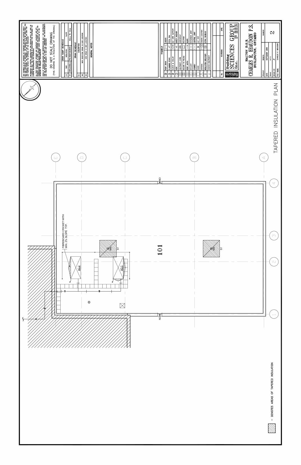
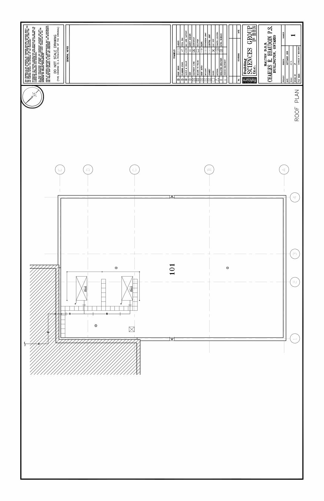
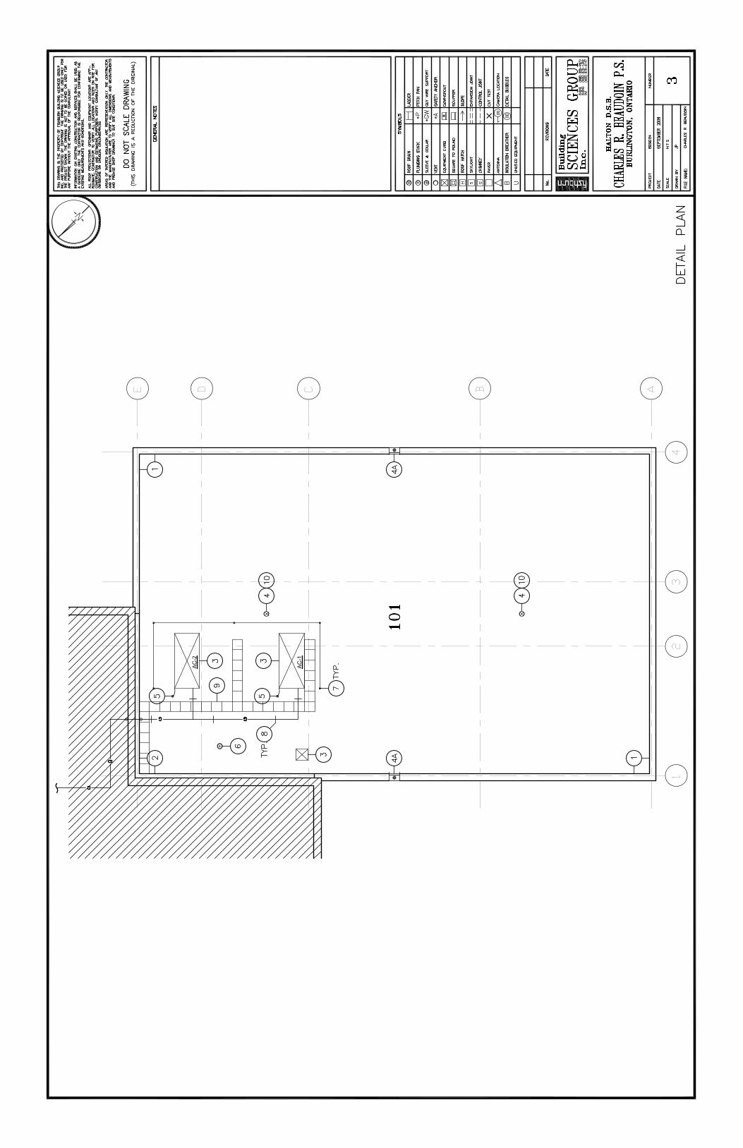
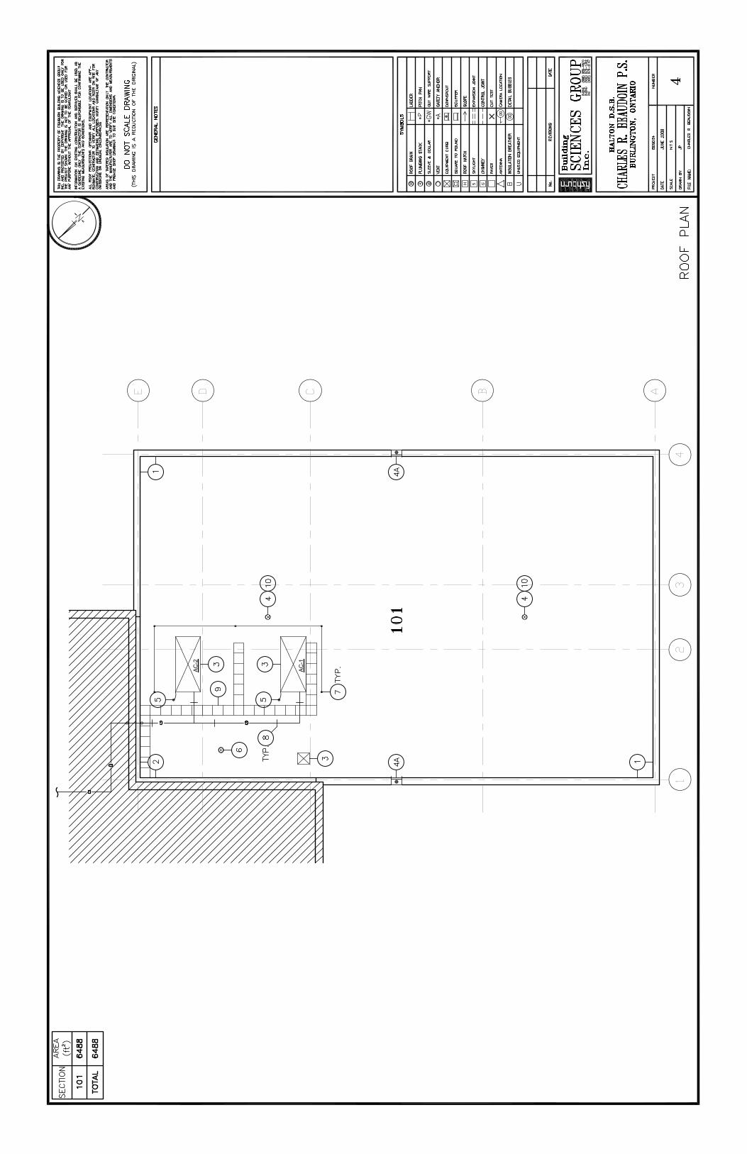
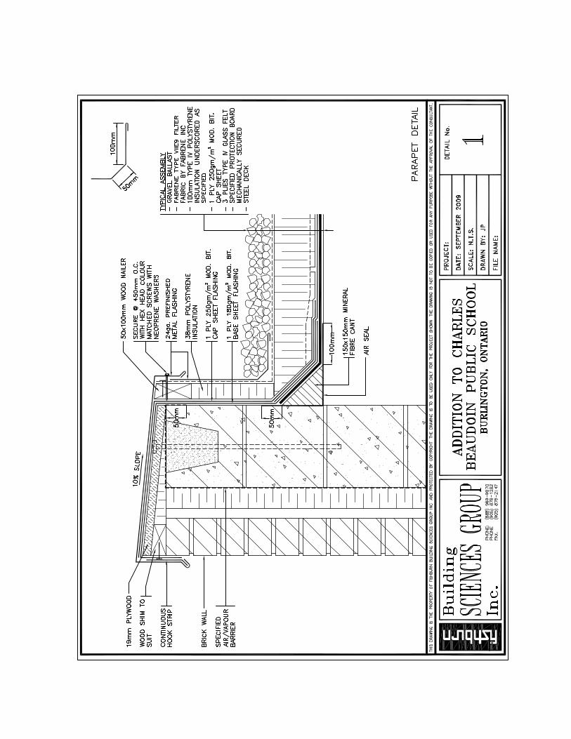
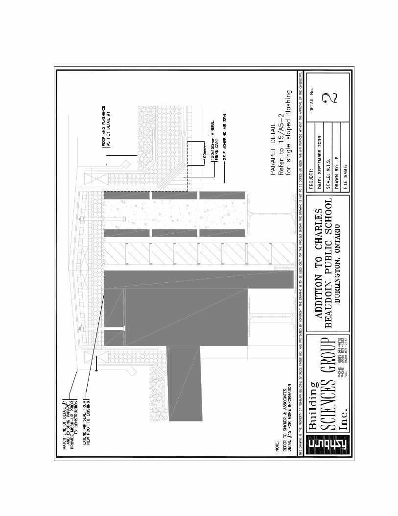
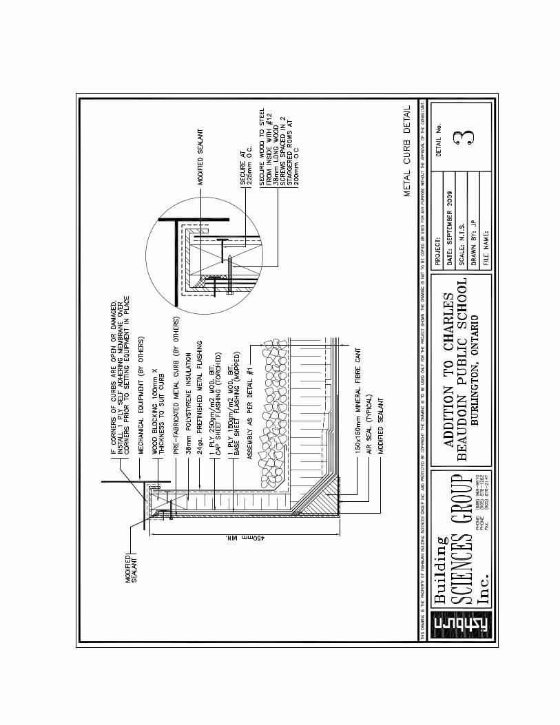
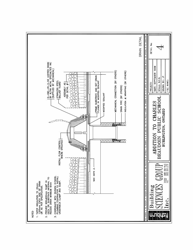
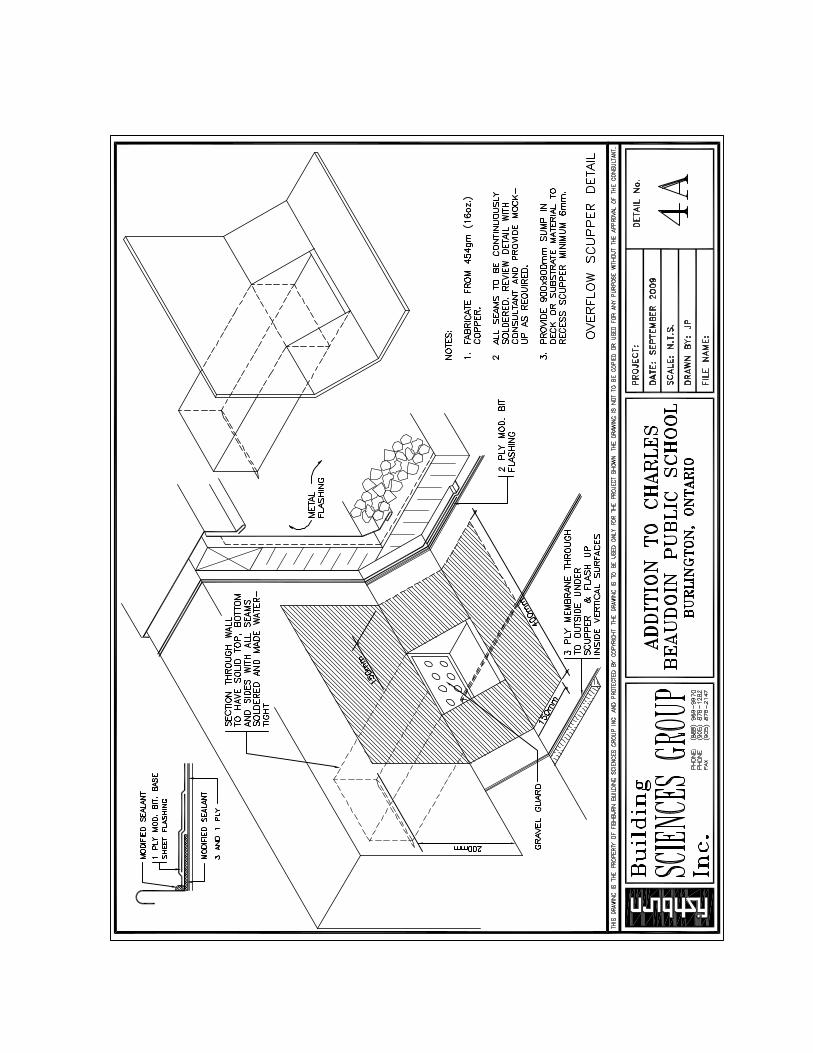
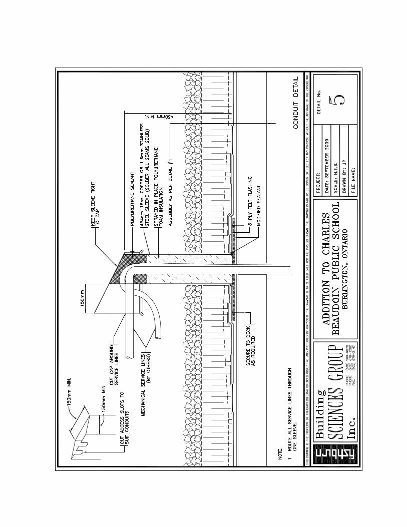
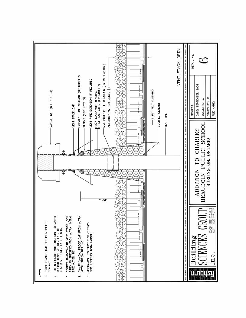
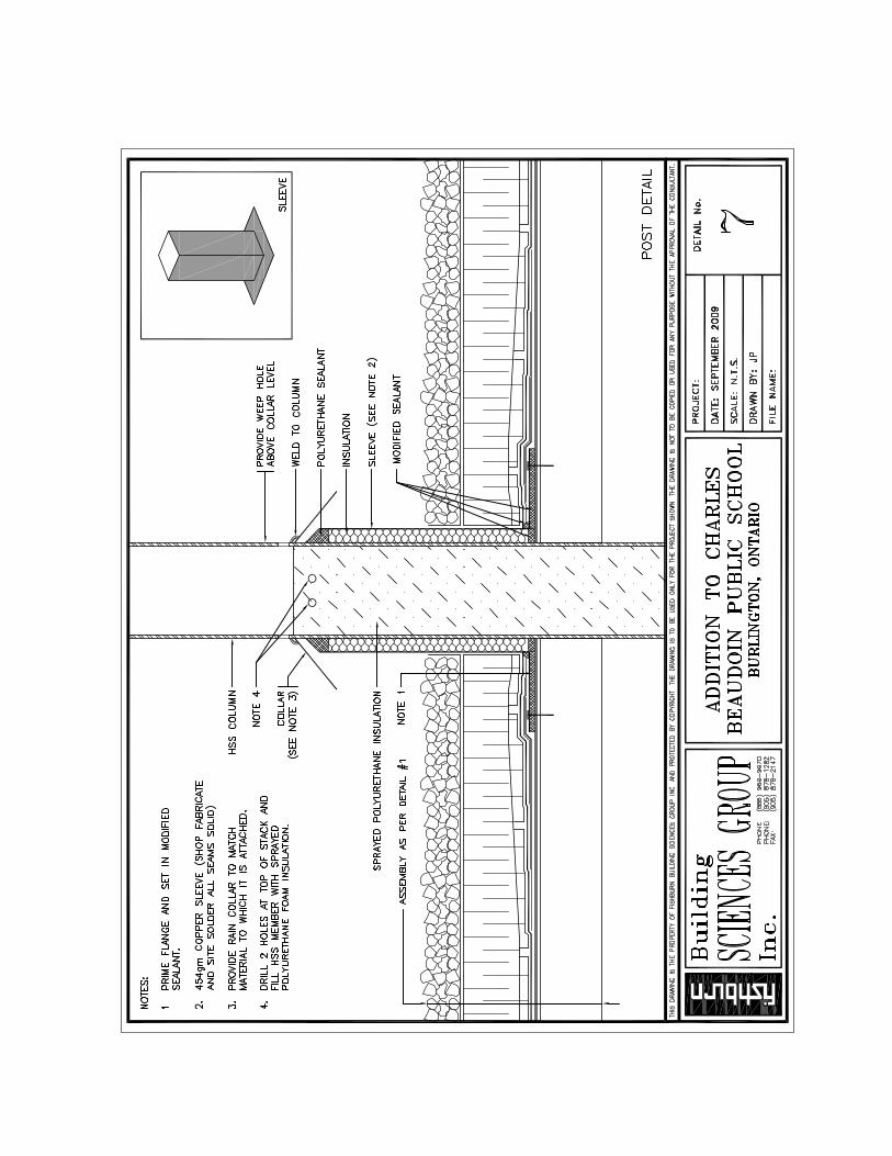
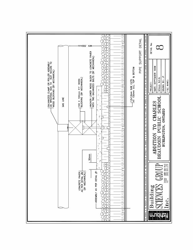
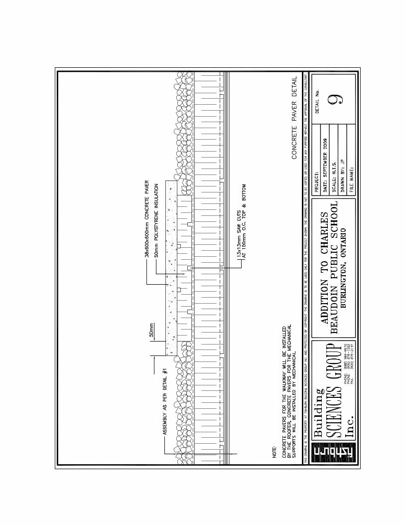
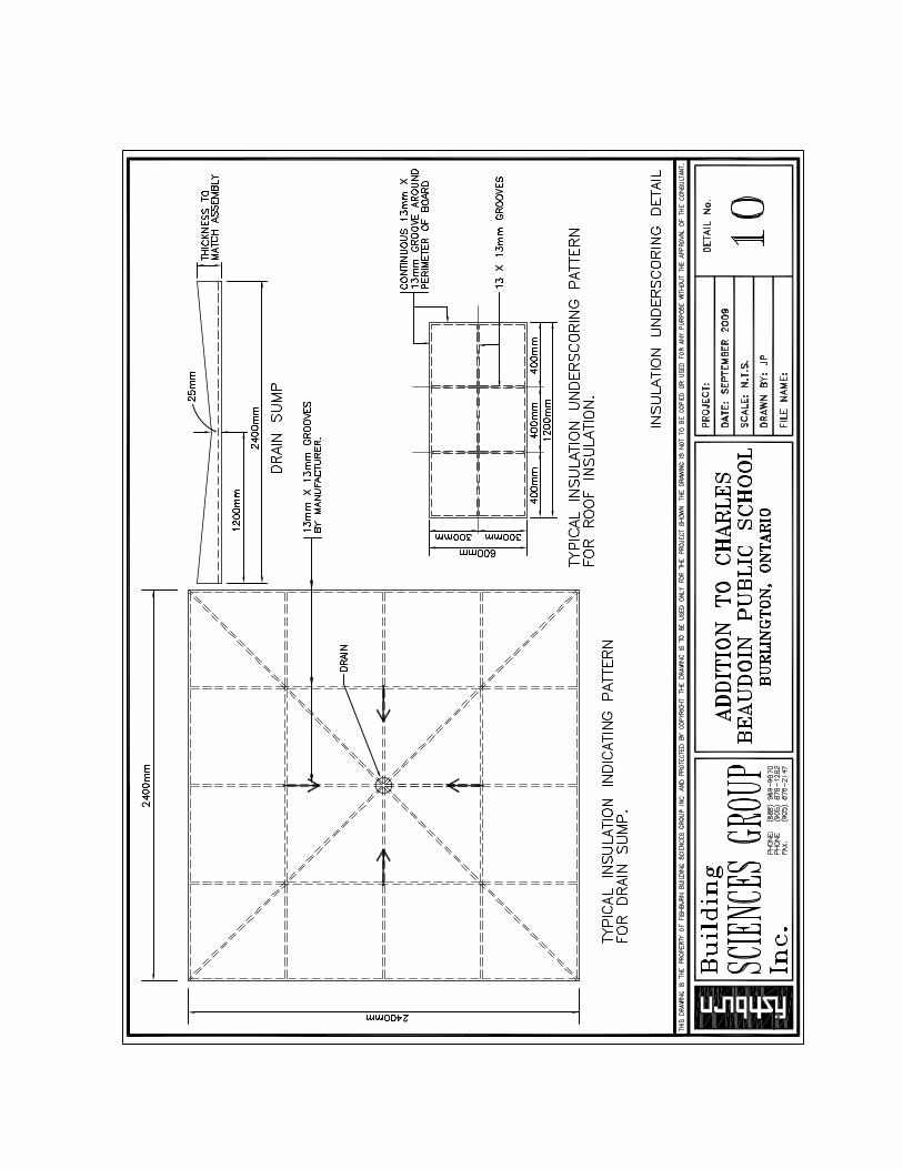
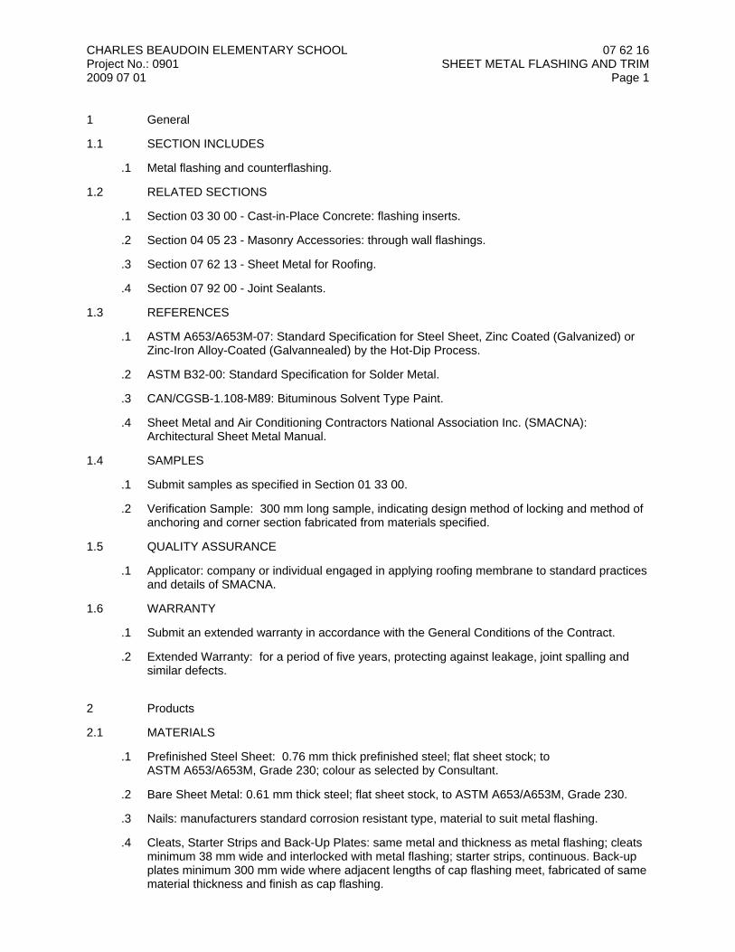
CHARLES BEAUDOIN ELEMENTARY SCHOOLProject No.: 09012009 07 01
07 62 16SHEET METAL FLASHING AND TRIM
Page 1
1 General
1.1 SECTION INCLUDES
.1 Metal flashing and counterflashing.
1.2 RELATED SECTIONS
.1 Section 03 30 00 - Cast-in-Place Concrete: flashing inserts.
.2 Section 04 05 23 - Masonry Accessories: through wall flashings.
.3 Section 07 62 13 - Sheet Metal for Roofing.
.4 Section 07 92 00 - Joint Sealants.
1.3 REFERENCES
.1 ASTM A653/A653M-07: Standard Specification for Steel Sheet, Zinc Coated (Galvanized) orZinc-Iron Alloy-Coated (Galvannealed) by the Hot-Dip Process.
.2 ASTM B32-00: Standard Specification for Solder Metal.
.3 CAN/CGSB-1.108-M89: Bituminous Solvent Type Paint.
.4 Sheet Metal and Air Conditioning Contractors National Association Inc. (SMACNA):Architectural Sheet Metal Manual.
1.4 SAMPLES
.1 Submit samples as specified in Section 01 33 00.
.2 Verification Sample: 300 mm long sample, indicating design method of locking and method ofanchoring and corner section fabricated from materials specified.
1.5 QUALITY ASSURANCE
.1 Applicator: company or individual engaged in applying roofing membrane to standard practicesand details of SMACNA.
1.6 WARRANTY
.1 Submit an extended warranty in accordance with the General Conditions of the Contract.
.2 Extended Warranty: for a period of five years, protecting against leakage, joint spalling andsimilar defects.
2 Products
2.1 MATERIALS
.1 Prefinished Steel Sheet: 0.76 mm thick prefinished steel; flat sheet stock; toASTM A653/A653M, Grade 230; colour as selected by Consultant.
.2 Bare Sheet Metal: 0.61 mm thick steel; flat sheet stock, to ASTM A653/A653M, Grade 230.
.3 Nails: manufacturers standard corrosion resistant type, material to suit metal flashing.
.4 Cleats, Starter Strips and Back-Up Plates: same metal and thickness as metal flashing; cleatsminimum 38 mm wide and interlocked with metal flashing; starter strips, continuous. Back-upplates minimum 300 mm wide where adjacent lengths of cap flashing meet, fabricated of samematerial thickness and finish as cap flashing.
CHARLES BEAUDOIN ELEMENTARY SCHOOLProject No.: 09012009 07 01
07 62 16SHEET METAL FLASHING AND TRIM
Page 2
.5 Screws, Bolts and Expansion Shields: non-ferrous metal compatible with adjacent surfaces.Exposed fastenings; same materials as metal surfaces through which they penetrate. Usecadmium plated screws with round heads suitable for soldering for galvanized work.
.6 Solder: to ASTM B32, 50 percent block tin, 50 percent pig lead.
.7 Flux: commercial hydrochloric acid cut with zinc, or 10-20 percent solution of orthophosphoricacid in water, for use with galvanized work.
.8 Sealant: as specified in Section 07 92 00.
.9 Flashing Paint: to CAN/CGSB-1.108-M; quick drying asphaltic base paint; eg. Primer 910-02by Bakor.
2.2 FABRICATION
.1 Shop fabricate flashing components as much as possible to requirements of applicablerequirements of SMACNA Architectural Manual.
.2 Form sheet metal on bending brake. Perform shaping, trimming and hand seaming on bench,where practicable, using proper sheet metal working tools.
.3 Fabricate material in clean shops, located away from areas where carbon steel is torch cut,ground, or cut with abrasive wheels to ensure that carbon steel dust will not be embedded inprefinished surfaces. Clean tools and dies which have been used on carbon steel prior tofabrication to prevent contamination of surface with carbon steel dust.
.4 Form sections square, true and accurate to size. Flashings shall be free from distortion, waves,twists, buckles or other defects detrimental to appearance and performance.
.5 Allow for thermal movement when forming, installing, interlocking and soldering sheet metalWork to avoid buckling, fullness of metal straining of joints or seams. Maximum length offlashing pieces; 2400 mm. Double back exposed edges at least 12 mm for appearance andstiffness.
.6 Fabricate flashings, copings, closures, plastic boxes, pipe sleeves and flashings for roofmounted equipment to details shown, unless otherwise indicated.
.7 Wipe and wash clean soldered joints immediately after joint is soldered to remove acid.
.8 Where soldered joints are absolutely necessary and where approved for use in prefinishedmetal, clean paint off both surfaces before soldering for minimum area necessary.
2.3 FINISHES
.1 Do not prime surfaces in direct contact bond with concrete or where field welding is required.
.2 Prime paint items with two coats.
.3 Galvanizing: to ASTM A653/A653M or CAN/CSA-G164-M, hot dipped method, minimum275 g/m2 zinc coating.
.4 Prefinished Steel: silicone modified polyester coating, applied to a minimum 0.025 mm dry filmthickness; eg. WeatherX by Valspar, multiple colours as selected by Consultant frommanufacturer's extended range of colours.
3 Execution
3.1 INSTALLATION
.1 Install sheet metal flashings with joints lapped, locked, cleated with "S" cleats and sealed orsoldered as required.
CHARLES BEAUDOIN ELEMENTARY SCHOOLProject No.: 09012009 07 01
07 62 16SHEET METAL FLASHING AND TRIM
Page 3
.2 Hem exposed edges 12 mm.
.3 Type of joints used shall be adequate for various conditions, subject to approval.
.4 Fabricate exposed fastening in such a manner to prevent water penetration at point offastening.
.5 Provide starter strips where indicated or required to present true, non-waving, leading edge.Anchor to back-up to provide rigid, secure installation.
.6 Make end joints where adjacent lengths of metal flashing meet using 300 mm long back-upflashing secured in place before installing flashing.
.7 Apply beads of sealant on face of back-up plate to seal ends of metal flashing.
.8 Leave 12 mm wide space between end of adjacent lengths of metal flashings.
.9 Fabricate back-up of same material and finish as metal flashing with which it is being used.Make back-up plate exact profile of flashing allowing for thickness of flashing joints.
.10 Form metal fascia with inner edge extended over fascia top and down cant to meet roofingaggregate. Nail with roofing nails and neoprene washers at 300 mm OC. Avoid placing nails inface of fascia, through membrane or flashing.
.11 Interlock counter flashing pieces with prefinished metal base flashing and fold locking seaminto position ensuring complete sealing. Continue counter flashing down to hemmed andsprung position at base of cant and junction of aggregate.
.12 Provide underlay of resin sized paper under sheet metal installed over masonry, concrete orwood. Lay underlay dry as sheet metal work is installed. Secure in place and lap joints100 mm.
.13 Imperfections in sheet metal work such as holes, dents, creases or oil-canning is cause forrejection.
.14 Repair damaged sheet metal work, wash entire installation down, and leave in neat condition.
.15 Provide flashings required for proper execution and completion of the Work in an acceptablemanner, including metal flashing around mechanical and other equipment occurring on theroof.
.16 Seal joints in sheet metal flashing, as specified in Section 07 92 00.
3.2 ADJUSTING
.1 Touch up marks and abrasions as installation proceeds.
.2 Discard dented panels.
.3 Defective materials or workmanship whenever found at any time prior to final acceptance ofthe work will be rejected regardless of previous acceptance.
END OF SECTION
07 81 00APPLIED FIREPROOFING
Page 1
CHARLES BEAUDOIN ELEMENTARY SCHOOLProject No.: 09012009 07 01
1 General
1.1 SECTION INCLUDES
.1 Spray-applied fire resistive materials.
.2 Refractory board fire protection.
1.2 RELATED SECTIONS
.1 Section 05 12 00 - Structural Steel Framing.
.2 Section 05 21 00 - Steel Joist Framing.
.3 Section 05 30 00 - Metal Decking.
.4 Section 07 21 00 - Thermal Insulation.
.5 Section 07 84 00 - Firestopping.
.6 Section 09 21 16 - Gypsum Board Assemblies.
1.3 REFERENCES
.1 ASTM E84-07b: Standard Test Method for Surface Burning Characteristics of BuildingMaterials.
.2 ASTM E119-07a: Standard Test Methods for Fire Tests of Building Construction and Materials.
.3 ASTM E605-93 (2006): Standard Test Methods for Thickness and Density of SprayedFire-Resistive Material (SFRM) Applied to Structural Members.
.4 ASTM E736-00 (2006): Standard Test Method for Cohesion / Adhesion of SprayedFire-Resistive Materials Applied to Structural Members.
.5 ASTM E759-92 (2005): Standard Test Method for Effect of Deflection on SprayedFire-Resistive Material Applied to Structural Members.
.6 ASTM E760-92 (2005): Standard Test Method for Effect of Impact on Bonding of SprayedFire-Resistive Material Applied to Structural Members.
.7 ASTM E761-92 (2005): Standard Test Method for Compressive Strength of SprayedFire-Resistive Material Applied to Structural Members.
.8 ASTM E859-93 (2006): Standard Test Method for Air Erosion of Sprayed Fire-ResistiveMaterials (SFRMs) Applied to Structural Members.
.9 AWCI Standard Practice for the Testing and Inspection of Field Applied Sprayed Fire-ResistiveMaterials.
.10 CAN/ULC-S101-04: Standard Methods of Fire Endurance Tests of Building Construction andMaterials.
.11 CAN4-S114-M80 (R1997): Standard Method of Test for Determination of Non-Combustibility inBuilding Materials.
.12 Underwriters Laboratories of Canada (ULC) List of Equipment and Materials.

07 81 00APPLIED FIREPROOFING
Page 2
CHARLES BEAUDOIN ELEMENTARY SCHOOLProject No.: 09012009 07 01
1.4 DESIGN REQUIREMENTS
.1 Spray-Applied Fire Resistive Coating.1 Deflection: When tested in accordance with ASTM E759, the material shall not crack or
delaminate when the non-concrete topped galvanized deck to which it is applied issubjected to a one time vertical centerload resulting in a downward deflection of 1/120thof the span.
.2 Bond Impact: When tested in accordance with ASTM E760, the material shall not crackor delaminate from the concrete topped galvanized deck to which it is applied.
.3 Cohesion/Adhesion (bond strength): When tested in accordance with ASTM E736, thematerial applied over uncoated or galvanized steel shall have an average bond strength of4.8 kPa.
.4 Air Erosion: When tested in accordance with ASTM E859, the material shall not besubject to losses from the finished application greater than 0.27 grams per square metre.
.5 Compressive Strength: When tested in accordance with ASTM E761, the material shallnot deform more than 10 percent when subjected to a crushing force of 35.9 kPa.
.6 Corrosion Resistance: When tested in accordance with ASTM E937, the material shallnot promote corrosion of steel.
.7 Non-combustibility: When tested in accordance with ASTM E136 or CAN4-S114-M, thematerial shall be noncombustible.
.8 Surface Burning Characteristics: When tested in accordance with ASTM E84 orCAN/ULC-S102, the material shall exhibit the following surface burning characteristics:.1 Flame Spread = 0.2 Smoke Developed = 0
.9 Density: When tested in accordance with ASTM E605, the material shall meet theminimum individual and average density values as listed in the appropriate UL/ULCdesign or as required by the authority having jurisdiction, or shall have a minimumaverage of 208 kg/m3.
.10 The material shall have been tested and reported by Underwriters Laboratories of Canada(ULC) in accordance with the procedures of CAN/ULC-S101.
.11 Spray-applied fire resistive materials shall be applied at the required thickness anddensity to achieve the ratings as noted on Drawings.
1.5 QUALITY ASSURANCE
.1 Installer: a firm with expertise in the installation of fire protection or similar materials; licensedor otherwise approved by the spray-applied fire resistive material manufacturer.
1.6 SUBMITTALS
.1 Submit Product data as specified in Section 01 33 00.
.2 Product Data: Include certifications, to show compliance with Contract Documents.
.3 Test Data: Submit independent laboratory test results for all specified performance criteria.
1.7 DELIVERY, STORAGE AND HANDLING
.1 Refer to Section 01 60 00.
.2 Deliver Products to the Place of the Work in manufacturer's unopened packages, fullyidentified as to trade name, type and other identifying data. Packaging shall bear the UL labelsfor fire hazard and fire-resistance classifications.
.3 Store Products above ground, in a dry location, protected from the weather. Removedamaged packages found unsuitable for use from the Place of the Work.
07 81 00APPLIED FIREPROOFING
Page 3
CHARLES BEAUDOIN ELEMENTARY SCHOOLProject No.: 09012009 07 01
1.8 PROJECT CONDITIONS
.1 When the prevailing outdoor temperature at the building is less than 4 degrees Celsius,maintain a minimum substrate and ambient temperature of 4 degrees Celsius prior to, duringand a minimum of 24 hours after application of the spray-applied fire resistive material.
.2 If necessary for job progress, provide heated protective enclosures to maintain temperatures. Refer to Section 01 50 00.
.3 Provide adequate ventilation of not less than 4 air changes per hour to allow proper drying ofthe spray-applied fire resistive material during and subsequent to its application.
1.9 SEQUENCING / SCHEDULING
.1 Perform fire protection work on a given floor prior to proceeding with fire protection work on thenext floor.
.2 Coordinate and schedule the fire protection work to avoid delays in the progress of the Work.
.3 Do not install board fire protection on structural members until piping and other constructionbehind the fire protection has been completed, uninterrupted coverage can be provided andthe need for subsequent cutting and patching can be eliminated.
2 Products
2.1 MANUFACTURERS
.1 Manufacturers of fire-resistive materials having Product considered acceptable for use:.1 Cafco Industries Inc..2 AD Fire Protection Systems..3 Grace Canada Inc.
.2 Substitutions: refer to Section 01 25 00.
2.2 MATERIALS
.1 Spray-Applied Fire Resistive Material: free of all forms of asbestos, including actinolite,amosite, anthophyllite, chrysotile, crocidolite and tremolite; eg. Cafco Blazeshield DC/F byCafco Industries Inc.
.2 Refractory Mineral Wool Board Fire Protection: Rigid boards of 144 kg/m3 (9 pcf) nominaldensity; produced from asbestos free materials by combining refractory mineral woolmanufactured from slag with thermosetting resin binders to comply with ASTM C612 for Class4 and as follows:.1 Thermal Resistance: RSI 0.76 @ 24 degrees C (R-4.35 @ 75 degrees F)..2 Surface Burning Characteristics: Flame Spread and Smoke Developed ratings of 15 and
5, respectively..3 Manufacturer and Product Name: eg. Cafco-board Mineral Wool Board Fire Protection by
Cafco Industries Inc.
.3 Fastening Accessories: For each fire resistive assembly in which mineral wool board fireprotection serves as rigid fire protection, provide a board fastening system complying with therelated UL design or other acceptable testing and inspecting organization's report.
.4 Water: Potable.
07 81 00APPLIED FIREPROOFING
Page 4
CHARLES BEAUDOIN ELEMENTARY SCHOOLProject No.: 09012009 07 01
3 Execution
3.1 EXAMINATION
.1 Refer to Section 01 71 00.
.2 Ensure surfaces to receive fire protection are free of oil, grease, loose mill scale, dirt,paints/primers (other than those listed and tested) or other foreign materials which wouldimpair satisfactory bonding to the surface.
.3 Ensure clips, hangers, supports, sleeves and other attachments to the substrate are to beplaced by others prior to the application of spray-applied fire resistive materials.
.4 Ensure that the installation of ducts, piping, conduit or other suspended equipment shall nottake place until the application of sprayed fire protection is complete in an area.
3.2 APPLICATION
.1 Apply fire resistive materials in accordance with the manufacturer's written applicationinstructions.
.2 Do not apply fire protection to steel floor decks prior to the completion of concrete work on thatdeck.
.3 Do not apply sprayed fire protection to the underside of roof deck until the roof is completelyinstalled and tight, all penthouses are complete, all mechanical units have been placed, and allroof traffic has ceased.
.4 Provide masking, drop cloths or other suitable coverings to prevent overspray from coming incontact with surfaces not intended to be sprayed.
.5 Apply bonding materials as per the identified ULC fire resistance design and themanufacturer's written recommendations.
.6 Topcoat materials shall be the type recommended and approved by the manufacturer of eachspray-applied fire resistive material required for the applications indicated.
.7 Install mineral wool board fire protection to comply with requirements for thicknesses, numberof layers, construction of joints and corners, and fastening methods referenced in theappropriate fire resistance design indicated.
.8 Coordinate installation of board fire protection with other construction to minimize cutting into,or removal of, already installed board material.
3.3 FIELD QUALITY CONTROL
.1 Test the spray-applied fire resistive material for thickness and density in accordance with oneof the following procedures:.1 ASTM E605 - Standard Test Method for Thickness and Density of Sprayed Fire-Resistive
Materials Applied to Structural Members..2 AWCI Standard Practice for the Testing and Inspection of Field-Applied Sprayed
Fire-Resistive Materials.
3.4 ADJUSTING
.1 Make Good damaged fire protection.

07 81 00APPLIED FIREPROOFING
Page 5
CHARLES BEAUDOIN ELEMENTARY SCHOOLProject No.: 09012009 07 01
3.5 PROTECTION
.1 Refer to Section 01 76 00.
.2 Protect completed installation.
.3 Provide final protection and maintain conditions in a manner acceptable to Consultant andauthorities having jurisdiction.
.4 Ensure fire protection is not damaged at time of Substantial Performance of the Work.
END OF SECTION
CHARLES BEAUDOIN ELEMENTARY SCHOOLProject No.: 09012009 07 01
07 84 00FIRESTOPPING
Page 1
1 General
1.1 SECTION INCLUDES
.1 Firestopping and smoke seals through penetrations at wall, floor and roof openings.
1.2 RELATED SECTIONS
.1 Section 03 30 00 - Cast-in-Place Concrete: penetrations in rated concrete assemblies.
.2 Section 04 22 00 - Concrete Unit Masonry: penetrations in rated masonry assemblies.
.3 Section 05 50 00 - Metal Fabrications: fire rated sleeves.
.4 Section 07 81 00 - Applied Fireproofing: sprayed fireproofing.
.5 Section 07 92 00 - Joint Sealants: non-rated joint sealants.
.6 Section 09 21 16 - Gypsum Board Assemblies: penetrations in rated gypsum board assem-blies.
1.3 REFERENCES
.1 ASTM C303-07: Standard Test Method for Dimensions and Density of Preformed Block andBoard-Type Thermal Insulation.
.2 ASTM E84-07b: Standard Test Method for Surface Burning Characteristics of BuildingMaterials.
.3 ASTM E119-07a: Standard Test Methods for Fire Tests of Building Construction and Materials.
.4 ASTM E814-06: Standard Test Method for Fire Tests of Through-Penetration Fire Stops.
.5 ASTM E2174-04: Standard Practice for On-Site Inspection of Installed Fire Stops.
.6 CAN/CGSB-19.13-M87: Sealing Compound, One Component, Elastomeric, Chemical Curing.
.7 CAN/CGSB-19.24-M90: Multicomponent, Chemical Curing Sealing Compound.
.8 CAN-ULC-S101-07: Standard Methods of Fire Endurance Tests of Building Construction andMaterials.
.9 CAN-ULC-S102-07: Standard Method of Test for Surface Burning Characteristics of BuildingMaterials and Assemblies.
.10 CAN-ULC-S114-05: Standard Method of Test for Determination of Non-Combustibility inBuilding Materials.
.11 CAN-ULC-S115-05: Standard Method of Fire Tests of Firestop Systems.
.12 CAN-ULC-S129-06: Standard Method of Test for Smoulder Resistance of Insulation (BasketMethod).
.13 CAN/ULC-S702-97: Standard for Thermal Insulation, Mineral Fibre, for Buildings.
.14 Underwriters' Laboratories of Canada: List of Equipment & Materials.
1.4 SYSTEM DESCRIPTION
.1 Seal empty holes and penetrations at floors, fire rated walls and smoke barrier walls.
.2 Seal holes accommodating penetrating items such as cables, cable trays, pipes, ducts andconduits.

CHARLES BEAUDOIN ELEMENTARY SCHOOLProject No.: 09012009 07 01
07 84 00FIRESTOPPING
Page 2
.3 Seal penetration system used to maintain the integrity of time rated construction by providing asealant against the spread of heat, flame and smoke.
.4 Systems shall be UL classified or listed by Warnock-Hersey International for the appropriaterequired time rating.
1.5 SUBMITTALS
.1 Submit Shop Drawings and Product data as specified in Section 01 33 00.
.2 Product Data: sealant manufacturer's installation instructions and standard drawings,indicating ULC or WHI test designations.
.3 Shop Drawings: Indicate sizes of openings, nature of penetrations, and tested method of firestop and smoke seal protection being proposed..1 Shop Drawings are to be sealed, signed and dated by manufacturer's design engineer..2 Submit shop drawings to Consultant and to the authority having jurisdiction for their
review and approval.
1.6 CERTIFICATES
.1 Submit certification as specified in Section 01 33 00.
.2 Certificate: sealant manufacturer's letter of certification verifying that Products meet or exceedspecified requirements.
1.7 TEST REPORTS
.1 Submit test reports as specified in Section 01 33 00.
.2 Test Reports: certified laboratory reports, indicating that Products proposed for use conform toASTM E814 and CAN-ULC-S115, and are so classified by the Underwriter's Laboratories ofCanada or Warnock-Hersey International.
1.8 QUALITY ASSURANCE
.1 Manufacturer's Design Engineer: a registered professional engineer licensed to practice in thePlace of the Work and having a minimum of 10 years documented experience designingfirestop and smoke seal systems.
.2 Applicator: approved and acceptable to sealant material manufacturer.
.3 Firestopping compounds shall not contain volatile solvents or require special application toprotect plastic pipe from firestopping compound.
1.9 PRE-INSTALLATION MEETING
.1 Prior to commencement of firestopping, arrange and conduct a pre-installation meeting asspecified in Section 01 31 00.
.2 Pre-installation Meeting: discuss proposed methods and materials to be used in instances.
.3 Representatives of the Owner, Consultant, Contractor, installer, manufacturer and the authorityhaving jurisdiction are to be in attendance. Do not conduct meeting unless identified partiesare present.
1.10 MOCK-UPS
.1 Construct job site mock-up as specified in Section 01 40 00.
.2 Apply one sample seal on representative substrates on each site for each fire rating required ateach type of wall, floor or roof construction.
CHARLES BEAUDOIN ELEMENTARY SCHOOLProject No.: 09012009 07 01
07 84 00FIRESTOPPING
Page 3
.3 Comply with project requirements as to thickness and density of application to achieve firerating.
.4 Proceed with installation only after Consultant has reviewed and accepted mock-up.
.5 Acceptable mockup may remain as part of the completed Work as standard.
1.11 DELIVERY, STORAGE AND HANDLING
.1 Refer to Section 01 60 00.
.2 Deliver Products to the Place of the Work in their original unopened packages.
.3 Store Products in an enclosed shelter, preventing damage to containers.
1.12 PROJECT CONDITIONS
.1 Do not apply sealants when temperature of substrate material and surrounding air is below5 degrees Celsius.
.2 Maintain sealant at a minimum 18 degrees Celsius for best workability.
2 Products
2.1 MANUFACTURERS
.1 Manufacturers of firestop sealants having Product considered acceptable for use:.1 3M..2 AD Fire Protection..3 Hilti Canada..4 Nuco Inc..5 Tremco..6 The Rectorseal Corporation.
.2 Substitutions: refer to Instructions to Bidders and Section 01 25 00.
2.2 MATERIALS
.1 Firestop Sealant Type A: single-component, water based, intumescent acrylic; ULC labelled;to CAN-ULC-S115 and CAN-ULC-S101-M; eg. TREMstop IA by Tremco.
.2 Firestop Sealant Type B: three component; epoxidized polyurethane terpolymer;accommodating joint movement of +40/-25%; ULC labelled; to CAN/CGSB-19.24-M and CAN-ULC-S115; eg. DYmeric 240 ULC by Tremco.
.3 Firestop Sealant Type C: three component; self-levelling; chemically curing polyurethanesealant; ULC labelled; to CAN-ULC-S115; eg. THC-900 ULC by Tremco.
.4 Firestop Sealant Type D: single component; low modulus; silicone rubber; moisture curing;ULC labelled; to CAN/CGSB-19.13-M and CAN-ULC-S115; eg. Fyre-Sil by Tremco.
.5 Firestop Sealant Type E: single component; modified polyurethane; moisture curing; ULClabelled; to CAN/CGSB-19.13-M and CAN-ULC-S115; eg. DYmonic ULC by Tremco.
.6 Primer: as recommended by sealant manufacturer for specific material, substrate and end use.
.7 Firestop Insulation: to CAN/ULC-S702, Type 2; mineral fibre manufactured from rock or slag,suitable for manual application:.1 Density: 72 kg/m3 when tested to ASTM C303..2 Combustibility: Noncombustible to CAN-ULC-S114..3 Melt Temperature: >1175 degrees C.
CHARLES BEAUDOIN ELEMENTARY SCHOOLProject No.: 09012009 07 01
07 84 00FIRESTOPPING
Page 4
.4 Surface Burning Characteristics: to CAN-ULC-S102, maximum flame spread of 0, smokedeveloped of 0.
.5 Moisture Sorption: 0.04 percent when tested to ASTM C1104.
.6 Smoulder Resistance: 0.01 percent when tested to CAN-ULC-S129.
2.3 COMPONENTS
.1 Provide firestopping and smoke sealing systems to CAN-ULC-S115 and as described below:.1 Asbestos free materials and systems fully capable of maintaining an effective barrier
against gases, flame and smoke in compliance with CAN-ULC-S115, not exceedingopening sizes stated.
.2 Service Penetration Assemblies: certified by CAN-ULC-S115 and used by ULC Guide 40U19. Service components listed as certified in this guide are noted under Label Service ofULC.
.2 Fire resistance rating of fire stopping material assembly must meet or exceed the fireresistance rating of the floor or wall section being penetrated.
.3 Firestopping and smoke seals at openings around penetrations for pipes, ductwork and othermechanical items requiring sound and vibration control: elastomeric seal; do not use acementitious or rigid seal at such locations.
.4 Damming and back up materials, supports and anchoring devices shall be to manufacturer'srecommendations, and in strict accordance with tested assembly being installed as acceptableto authorities having jurisdiction.
.5 Sealants: non-sagging type for vertical joints.
3 Execution
3.1 EXAMINATION
.1 Refer to Section 01 71 00.
.2 Confirm compatibility of surfaces to receive sealant materials.
.3 Verify surfaces of openings are sound, clean, dry and ready to receive application of sealant.
.4 Verify that penetration elements are securely fixed and properly located.
3.2 PREPARATION
.1 Protect adjacent surfaces and equipment from damage.
.2 Clean contact surfaces of dirt, dust, grease, oil, loose material, or other matter which mayaffect bond of sealant.
.3 Remove incompatible materials which affect bond by scraping, brushing, water or solventcleaning, or sandblasting.
3.3 APPLICATION
.1 Install mineral fibre insulation in compacted thicknesses required by ULC design. Compressinsulation approximately 33 percent.
.2 Apply sealant in strict accordance with manufacturer's instructions and ULC certification.
.3 Coordinate and cooperate with adjacent, contiguous and related materials trades, such asconcrete, drywall, plumbing, conduit, electrical wiring, communication systems, etc., to ensurea proper and timely installation.
.4 Seal holes or voids made by penetrating items to ensure an effective fire and smoke barrier.

CHARLES BEAUDOIN ELEMENTARY SCHOOLProject No.: 09012009 07 01
07 84 00FIRESTOPPING
Page 5
.5 Seal intersections and penetrations of floors, ceilings, walls and columns.
.6 Seal around cutouts for lights, cabinets, pipes and plumbing, ducts, electrical boxes, etc.
.7 Wrap non-insulated heated pipes that may be subject to movement with a non-combustiblesmooth material to permit the pipe to move without damaging the firestopping and smoke seal.
.8 Maintain the integrity of any insulation and vapour retarders on insulated pipes and ducts at thefire separation.
.9 Where floor openings exceed 100 mm in width and may be subjected to traffic or loading,install cover plate systems capable of supporting same loading as floor.
3.4 FIELD QUALITY CONTROL
.1 Perform field testing and inspection as specified in Section 01 40 00.
.2 Conduct inspections to ASTM E2174.
.3 Examine finished penetrations to ensure proper installation before concealing or enclosing anyareas of work.
.4 Keep areas of work accessible until inspection has been completed.
.5 Manufacturer's Field Service: inspect to verify and confirm that systems installation is in strictaccordance with manufacturer's and ULC requirements.
.6 Correct unacceptable work and provide further inspection to verify compliance withrequirements.
3.5 CLEANING
.1 Refer to Section 01 74 00.
.2 Immediately remove spots, smears, stains, residues, adhesives, etc., from installation,including from adjacent surfaces.
.3 Do not use Products containing volatile solvents.
.4 Leave the Work in a clean and satisfactory condition.
3.6 PROTECTION
.1 Refer to Section 01 76 00.
.2 Protect firestopping assemblies from damage until Owner occupancy.
.3 Make Good damaged firestopping assemblies.
END OF SECTION
CHARLES BEAUDOIN ELEMENTARY SCHOOLProject No.: 09012009 07 01
07 92 00JOINT SEALANTS
Page 1
1 General
1.1 SECTION INCLUDES
.1 Joint sealing.
1.2 RELATED SECTIONS
.1 Section 03 30 00 - Cast-In-Place Concrete: sealants used in conjunction with concrete.
.2 Section 04 05 00 - Common Work Results for Masonry: sealants used in conjunction withmasonry.
.3 Section 06 40 00 - Architectural Woodwork: sealants used in conjunction with counters andcasework.
.4 Section 07 26 00 - Self-Adhered Membrane Air and Vapour Retarders: sealants used inconjunction with building envelope vapour seal continuity.
.5 Section 07 50 19 - Sealants for Roofing: sealants used in conjunction with roofing.
.6 Section 07 62 16 - Sheet Metal Flashing and Trim: sealants used in conjunction with sheetmetal flashing.
.7 Section 07 84 00 - Firestopping: firestop sealants.
.8 Section 08 11 13 - Hollow Metal Frames: sealants used in conjunction with hollow metalframes.
.9 Section 08 41 13 - Aluminum Entrances and Storefronts: sealants used in conjunction withmetal frames.
.10 Section 08 44 13 - Glazed Aluminum Curtain Wall: sealants used in conjunction with metalframes.
.11 Section 08 51 13 - Aluminum Windows: sealants used in conjunction with metal frames.
.12 Section 08 80 00 - Glazing: sealants used in conjunction with glazing methods.
.13 Section 09 21 16 - Gypsum Board Assemblies: sealants used in conjunction with acoustictreatment.
.14 Section 09 51 23 - Acoustical Tile Ceilings: sealants used in conjunction with suspended metalceiling systems.
1.3 REFERENCES
.1 ASTM C920-05: Standard Specification for Elastomeric Joint Sealants.
.2 CAN/CGSB-19.13-M87: Sealing Compound, One Component, Elastomeric, Chemical Curing.
.3 CAN/CGSB-19.17-M90: One Component Acrylic Emulsion Base Sealing Compound.
.4 CAN/CGSB-19.24-M90: Multicomponent, Chemical Curing Sealing Compound.
1.4 SYSTEM DESCRIPTION
.1 Seal gaps between dissimilar Products and equipment, visible or otherwise, to protect buildingcomponents from air infiltration and moisture penetration.
1.5 SUSTAINABLE DESIGN REQUIREMENTS
.1 Use low-emitting sealants conforming to CARB requirements.
CHARLES BEAUDOIN ELEMENTARY SCHOOLProject No.: 09012009 07 01
07 92 00JOINT SEALANTS
Page 2
1.6 QUALITY ASSURANCE
.1 Arrange for sealant manufacturer's representative to be present prior to commencement ofcaulking. Consult with representative as to joint conditions.
.2 Applicator: company specializing in applying the work of this Section with three yearsdocumented experience.
1.7 DELIVERY, STORAGE AND HANDLING
.1 Refer to Section 01 60 00.
.2 Deliver Products in manufacturer's sealed packages.
.3 Store Products in warm, dry conditions.
1.8 PROJECT CONDITIONS
.1 Do not install solvent curing sealants in enclosed building spaces.
.2 Maintain temperature and humidity recommended by the sealant manufacturer during and afterinstallation.
1.9 WARRANTY
.1 Submit extended warranties in accordance with the General Conditions of the Contract.
.2 System Warranty: 2 year extended warranty including coverage of installed sealants andaccessories which fail to achieve air tight and watertight seal, exhibit loss of adhesion orcohesion, or do not cure.
2 Products
2.1 MANUFACTURERS
.1 Substitutions: refer to Instructions to Bidders and Section 01 25 00.
2.2 MATERIALS
.1 Exterior Weatherseal Sealant: to CAN/CGSB-19.24-M, Type II, Class B; three-part, epoxidizedpolyurethane; chemically curing; accommodating joint movement of plus or minus 50 percent;DYmeric 240FC by Tremco or Sonneborn NP2 by BASF; colours as selected by Consultant.
.2 Glazing Sealant: one part, moisture curing, acetoxy silicone sealant; to CAN/CGSB-19.13-M,Type MG-2-25-A-L; Tremco Proglaze or Dow Corning 999A, Clear colour.
.3 Mildew-Resistant Interior Sealant for Washroom Areas: to ASTM C920, Type S, Grade NS,Class 25, Use NT; one-part, fungicidal silicone rubber; Dow Corning 786; White colour.
.4 Acoustical and General Purpose Interior Sealant: to CAN/CGSB-19.17-M; one-part, siliconizedacrylic latex, mildew-resistant, accommodating joint movement of plus or minus 12-1/2 percent;Tremco Tremflex 834; White colour.
2.3 ACCESSORIES
.1 Primer: non-staining type, recommended by sealant manufacturer to suit application.
.2 Joint Cleaner: non-corrosive and non-staining type, recommended by sealant manufacturer;compatible with joint forming materials.
.3 Joint Backing: open cell polyethylene foam core wrapped in a closed cell polyethylene skin.
CHARLES BEAUDOIN ELEMENTARY SCHOOLProject No.: 09012009 07 01
07 92 00JOINT SEALANTS
Page 3
.4 Bond Breaker: pressure sensitive tape recommended by sealant manufacturer to suitapplication.
3 Execution
3.1 PREPARATION
.1 Clean and prime joints to requirements of manufacturer's instructions.
.2 Remove loose materials and foreign matter which might impair adhesion of sealant.
3.2 APPLICATION
.1 Install sealant to requirements of manufacturer's instructions.
.2 Seal gaps between dissimilar materials to prevent air infiltration and moisture penetration.
.3 Seal visible and unsightly gaps between dissimilar materials.
.4 Measure joint dimensions and size materials to achieve required width-to-depth ratios.
.5 Install joint backing to achieve a neck dimension no greater than one-third joint width.
.6 Install bond breaker where joint backing is not used.
.7 Tool joints to concave shape. Remove excess material.
3.3 FIELD QUALITY CONTROL
.1 Field inspection will be conducted by Consultant as specified in Section 01 40 00.
.2 Joints filled with only a skin bead or insufficient volume of sealant will be rejected.
.3 Remove material from rejected joints, clean and re-seal to attain proper width-to-depth jointcoverage.
3.4 CLEANING
.1 Refer to Section 01 74 00.
.2 Clean adjacent soiled surfaces.
.3 Make Good surfaces that have become defaced or disfigured as a result of sealant application.
END OF SECTION
CHARLES BEAUDOIN ELEMENTARY SCHOOLProject No.: 09012009 07 01
08 11 13HOLLOW METAL FRAMES
Page 1
1 General
1.1 SECTION INCLUDES
.1 Hollow metal frames, non-rated and fire rated types.
1.2 RELATED SECTIONS
.1 Section 04 05 10 - Masonry Mortaring and Grouting: mortar fill of frames.
.2 Section 07 92 00 - Joint Sealants.
.3 Section 08 13 13 - Hollow Metal Doors.
.4 Section 08 14 00 - Wood Doors.
.5 Section 08 71 00 - Door Hardware.
.6 Section 08 80 00 - Glazing: glazing of hollow metal screens.
.7 Section 09 90 00 - Painting and Coating: site finishing of frames.
1.3 REFERENCES
.1 ASTM A653/A653M-07: Standard Specification for Steel Sheet, Zinc Coated (Galvanized) orZinc-Iron Alloy-Coated (Galvannealed) by the Hot-Dip Process.
.2 Canadian Steel Door and Frame Manufacturer's Association: Manufacturing Standard for SteelDoors and Frames.
.3 Canadian Steel Door and Frame Manufacturer's Association: Manufacturing Specifications forSteel Doors and Frames.
.4 Canadian Steel Door and Frame Manufacturer's Association: Canadian Fire Labelling Guidefor Steel Doors and Frames.
.5 Canadian Steel Door and Frame Manufacturer's Association: Canadian Metric Guide for SteelDoors and Frames (Modular Construction).
.6 CSA W59-03: Welded Steel Construction (Metal Arc Welding).
.7 CAN/CGSB-1.40-97: Anticorrosive Structural Steel Alkyd Primer.
.8 NAAMM HMMA 840-99: Hollow Metal Manual.
.9 NFPA 80-2007: Fire Doors and Other Opening Protectives.
.10 Underwriters Laboratories of Canada: List of Equipment and Materials.
1.4 SUBMITTALS
.1 Submit Shop Drawings and Product data as specified in Section 01 33 00.
.2 Shop Drawings: Indicate frame configuration, anchor types and spacings, location of cut outsfor hardware, reinforcement, and finish.
.3 Product Data: manufacturer's standard data sheets illustrating standard frame constructionand knock down frames.
CHARLES BEAUDOIN ELEMENTARY SCHOOLProject No.: 09012009 07 01
08 11 13HOLLOW METAL FRAMES
Page 2
1.5 QUALITY ASSURANCE
.1 Conform to requirements of Canadian Steel Door and Frame Manufacturers Associationstandards.
.2 Welding: to CSA W59.
.3 Installed frame and door assembly to conform to National Fire Protection Associationstandards for fire rated class indicated in schedule.
1.6 DELIVERY, STORAGE AND HANDLING
.1 Refer to Section 01 60 00.
.2 Store hollow metal frames to HMMA 840.
2 Products
2.1 MANUFACTURERS
.1 Manufacturers of hollow metal frames having Product considered acceptable for use:.1 Artek Door Limited..2 Baron Metal Industries..3 Daybar..4 S. W. Fleming..5 Metal Door Limited.
.2 Substitutions: refer to Instructions to Bidders and Section 01 25 00.
2.2 MATERIALS
.1 Standard Hollow Metal Frame: 1.6 mm thick, cold-rolled commercial quality steel; paintablegalvanneal finish; fire rating as scheduled; sizes as indicated on Drawings; eg. F-Series Frameby Fleming Door Products Ltd.
.2 Double Egress Hollow Metal Frame: 1.6 mm thick, cold-rolled commercial quality steel;paintable galvanneal finish; fire rating as scheduled; sizes as indicated on Drawings; eg. DE-Series Frame by Fleming Door Products Ltd.
.3 Frame Anchors: regular galvanneal steel, as follows:.1 T-Strap Type: 1.2 mm thick..2 Stirrup-strap Type: 50 x 250 mm size, 1.6 mm thick..3 Jamb Floor Type: 1.6 mm thick..4 Stud Type: 1.0 mm thick.
.4 Jamb Spreaders: regular galvanneal steel, 1.0 mm thick.
.5 Mortar Guard Boxes: regular galvanneal steel, 0.8 mm thick.
.6 Reinforcements: galvannealed steel, thicknesses as follows:.1 Flush Bolt, Lock and Strike Reinforcement: 1.6 mm.2 Hinge Reinforcements: 3.5 mm..3 Door Closer and Holder Reinforcements: 2.8 mm.
.7 Glazing Stops: rolled steel channel shape, butted corners; prepared for countersink styletamper-proof screws.
.8 Bumpers: resilient rubber.
.9 Bituminous Coating: fibrous asphalt emulsion.
.10 Joint Sealer: as specified in Section 07 92 00.
CHARLES BEAUDOIN ELEMENTARY SCHOOLProject No.: 09012009 07 01
08 11 13HOLLOW METAL FRAMES
Page 3
2.3 FABRICATION
.1 Fabricate frames as welded units.
.2 Unless indicated otherwise on Drawings, fabricate frames with fixed mullions, to profilesshown, with hardware reinforcement plates welded in place. Conform to standards andspecifications published by the Canadian Steel Door and Frame Manufacturer's Association.
.3 Welding: to CSA W59. Grind exposed welds smooth and flush. Fill open joints, seams, anddepressions with filler or by continuous brazing or welding. Grind smooth to true sharp arrisesand profiles. Sand to a smooth, true, uniform finish.
.4 Mitre corners of frames. Cut frame mitres accurately and weld continuously on inside of frame.
.5 Protect strike and hinge reinforcements and other openings with mortar guard boxes welded toframe.
.6 Reinforce frames wider than 1.2 metres with roll formed steel channels fitted tightly into framehead, flush with top.
.7 Fit frames with channel or angle spreaders, minimum two per frame, to ensure proper framealignment. Install stiffener plates to spreaders between frame trim where required to preventbending of trim and to maintain alignment when setting and during construction.
.8 Provide adjustable T-strap anchors in frames to be installed in masonry openings, spaced at600 mm OC.
.9 Where floor finish allows, fabricate frames to extend at least 38 mm below finished floor.
.10 Where frames are required to terminate at finished floor, Provide plates for anchorage to floorslab.
.11 Prepare interior door frames for single stud door silencers, 3 for single door frames and 2 fordouble door frames.
.12 Fabricate fire-rated door frames in accordance with Canadian Fire Labelling Guide for SteelDoors and Frames as published by the Canadian Steel Door and Frame Manufacturer'sAssociation.
.13 Fabricate doors and screens to accommodate scheduled glazing. Secure glazing stops toframes with counter sunk oval head sheet metal screws.
.14 Preparation for Hardware:.1 Prepare frames for heavy weight oversize butt hinges, continuous hinges, cylindrical
locksets, rim and concealed vertical rod / mortise lock case exit devices, magnetic locks,surface door closers and concealed overhead stops.
.2 Conform to approved finish hardware schedule.
.3 Blank, mortise, reinforce, drill and tap frames to receive templated hardware, as required. Coordinate with Section 08 71 00.
2.4 FINISHES
.1 Paintable Galvanneal Coating: streak-free matte grey appearance, to ASTM A653/A653M,ZF120 coating designation, minimum 120 g/m2 zinc-iron coating.
.2 Regular Galvanneal Coating: streak-free matte grey appearance, to ASTM A653/A653M,ZF75 coating designation, minimum 75 g/m2 zinc-iron coating.
.3 Shop Primer: to CAN/CGSB-1.40.
CHARLES BEAUDOIN ELEMENTARY SCHOOLProject No.: 09012009 07 01
08 11 13HOLLOW METAL FRAMES
Page 4
3 Execution
3.1 INSTALLATION
.1 Install frames to HMMA 840.
.2 Coordinate with masonry and wallboard construction for anchor placement.
.3 Fill frames solid with non-shrink grout.
.4 Seal openings between frames and walls as specified in Section 07 92 00.
END OF SECTION
CHARLES BEAUDOIN ELEMENTARY SCHOOLProject No.: 09012009 07 01
08 13 13HOLLOW METAL DOORS
Page 1
1 General
1.1 SECTION INCLUDES
.1 Hollow metal doors, non-rated and fire rated types.
1.2 RELATED SECTIONS
.1 Section 08 11 13 - Hollow Metal Frames.
.2 Section 08 71 00 - Door Hardware.
.3 Section 08 80 00 - Glazing.
.4 Section 09 90 00 - Painting and Coating.
1.3 REFERENCES
.1 ANSI/DHI A115.IG-1994: Installation Guide for Doors and Hardware.
.2 ASTM A653/A653M-07: Standard Specification for Steel Sheet, Zinc Coated (Galvanized) orZinc-Iron Alloy-Coated (Galvannealed) by the Hot-Dip Process.
.3 Canadian Steel Door and Frame Manufacturer's Association: Manufacturing Standard for SteelDoors and Frames.
.4 Canadian Steel Door and Frame Manufacturer's Association: Manufacturing Specifications forSteel Doors and Frames.
.5 Canadian Steel Door and Frame Manufacturer's Association: Canadian Fire Labelling Guidefor Steel Doors and Frames.
.6 Canadian Steel Door and Frame Manufacturer's Association: Canadian Metric Guide for SteelDoors and Frames (Modular Construction).
.7 CSA W59-03: Welded Steel Construction (Metal Arc Welding).
.8 CAN/CGSB-1.40-97: Anti-corrosive Structural Steel Alkyd Primer.
.9 CAN/ULC-S702-97: Standard for Thermal Insulation, Mineral Fibre, for Buildings.
.10 NAAMM HMMA 840-99: Hollow Metal Manual.
.11 NFPA 80-2007: Fire Doors and Other Opening Protectives.
.12 Underwriters Laboratories of Canada: List of Equipment and Materials.
1.4 SUBMITTALS
.1 Submit Shop Drawings and Product data as specified in Section 01 33 00.
.2 Shop Drawings: Indicating door elevations, internal reinforcement, closure method, location ofcut outs for hardware, glazing and louvres, and finish.
.3 Product Data: manufacturer's standard data sheet illustrating standard door construction.
1.5 QUALITY ASSURANCE
.1 Conform to Canadian Steel Door and Frame Manufacturers Association standards.
.2 Welding: to CSA W59.
.3 Fire Rated Door Assembly: to National Fire Protection Association requirements for fire ratedclass indicated in schedule.
CHARLES BEAUDOIN ELEMENTARY SCHOOLProject No.: 09012009 07 01
08 13 13HOLLOW METAL DOORS
Page 2
1.6 DELIVERY, STORAGE AND HANDLING
.1 Refer to Section 01 60 00.
.2 Store hollow metal doors to HMMA 840.
2 Products
2.1 MANUFACTURERS
.1 Manufacturers of hollow metal doors having Product considered acceptable for use:.1 Artek Door Limited..2 Baron Metal Industries..3 Daybar..4 S. W. Fleming..5 Metal Door Limited.
.2 Substitutions: refer to Instructions to Bidders and Section 01 25 00.
2.2 MATERIALS
.1 Hollow Metal Doors: 45 mm thick, fire rating as scheduled; constructed as follows:.1 Door Faces: 1.6 mm thick commercial quality steel sheet faces, flush design, paintable
galvanneal finish..2 Vertical Steel Stiffeners: 0.91 mm thick commercial quality steel profiles, interlocking
design, galvannealed finish..3 Core: 45 mm thick semi-rigid mineral fibre insulation, to CAN/ULC-S702, Type 1;
minimum RSI 0.68 per 25 mm of thickness.
.2 Reinforcements: steel, regular galvanneal finish, thicknesses as follows:.1 Flush Bolt, Lock and Strike Reinforcement: 1.6 mm.2 Hinge Reinforcements: 3.5 mm..3 Door Closer and Holder Reinforcements: 2.8 mm.
.3 Glazing Stops: Rolled steel channel shape, butted corners; prepared for countersink styletamper-proof screws.
.4 Bituminous Coating: Fibrous asphalt emulsion.
2.3 FABRICATION
.1 Fabricate doors to CAN/CGSB-82.5-M and to the standards and specifications published bythe Canadian Steel Door and Frame Manufacturer's Association.
.2 Provide continuous faces free from joints, tool markings and abrasions; with hardwarereinforcement plates welded in place.
.3 Welding: to CSA W59. Grind exposed welds smooth and flush. Fill open joints, seams, anddepressions with filler or by continuous brazing or welding. Grind smooth to true sharp arrisesand profiles. Sand to a smooth, true, uniform finish.
.4 Fabricate fire-rated doors in accordance with Canadian Fire Labelling Guide for Steel Doorsand Frames as published by the Canadian Steel Door and Frame Manufacturer's Association.
.5 Fabricate doors to accommodate scheduled glazing. Secure glazing stops to doors withcounter sunk oval head sheet metal screws.
.6 Prepare doors for heavy weight oversize butt hinges, continuous hinges, cylindrical locksets,rim and concealed vertical rod / mortise lock case exit devices, magnetic locks, surface doorclosers and concealed overhead stops. Conform to approved finish hardware schedule.
CHARLES BEAUDOIN ELEMENTARY SCHOOLProject No.: 09012009 07 01
08 13 13HOLLOW METAL DOORS
Page 3
.7 Blank, mortise, reinforce, drill and tap doors to receive templated hardware, as required. Coordinate with Section 08 71 00.
.8 Reinforce and stiffen doors with vertical steel stiffeners spaced at 152 mm OC, continuous forfull height of door, spot welded to both door faces.
.9 Completely fill door cores with specified core materials.
.10 Reinforce door edges with channel reinforcing.
.11 Continuously weld seam between faces and door edges. Bevel stiles minimum 3 mm.
.12 Provide flush top edge and bottom closures on exterior doors, sealed watertight.
2.4 FINISHING
.1 Paintable Galvanneal Coating: streak-free matte grey appearance, to ASTM A653/A653M,ZF120 coating designation, minimum 120 g/m2 zinc-iron coating.
.2 Regular Galvanneal Coating: streak-free matte grey appearance, to ASTM A653/A653M,ZF75 coating designation, minimum 75 g/m2 zinc-iron coating.
.3 Shop Primer: to CAN/CGSB-1.40.
3 Execution
3.1 INSTALLATION
.1 Install doors to HMMA 840, ANSI/DHI A115.IG and Canadian Steel Door and FrameManufacturers Association standards.
3.2 TOLERANCES
.1 Maximum Diagonal Distortion After Installation: 1.5 mm measured with straight edge, corner tocorner.
END OF SECTION
CHARLES BEAUDOIN ELEMENTARY SCHOOLProject No.: 09012009 07 01
08 14 00WOOD DOORS
Page 1
1 General
1.1 SECTION INCLUDES
.1 Wood doors.
1.2 RELATED SECTIONS
.1 Section 06 20 00 - Finish Carpentry.
.2 Section 06 24 00 - Laminated Plastics.
.3 Section 08 11 13 - Hollow Metal Frames.
.4 Section 08 71 00 - Door Hardware.
.5 Section 08 80 00 - Glazing.
.6 Section 09 90 00 - Painting and Coating: site finishing of wood doors.
1.3 REFERENCES
.1 Architectural Woodwork Manufacturers Association of Canada (AWMAC): ArchitecturalWoodwork Quality Standards Illustrated.
.2 ANSI A208.1-99: Particleboard.
.3 ANSI/DHI A115.IG-1994: Installation Guide for Doors and Hardware.
.4 ANSI/NEMA LD 3-2000: High Pressure Decorative Laminate.
.5 CAN/CSA-O132.2 Series-90: Wood Flush Doors.
1.4 SUBMITTALS
.1 Submit Shop Drawings as specified in Section 01 33 00.
.2 Shop Drawings: Indicate door elevations, stile and rail reinforcement, internal blocking forhardware attachment, and cutouts.
1.5 QUALITY ASSURANCE
.1 Conform to AWMAC Quality Standards - Institutional Grade.
1.6 DELIVERY, STORAGE AND HANDLING
.1 Refer to Section 01 60 00.
.2 Pile doors flat on level supports to prevent warping.
.3 Protect face of first door unit by placing plywood or cardboard between supports and door. Cover the top door unit in a similar manner.
.4 Store doors in a dry, well-ventilated area.
1.7 WARRANTY
.1 Provide a five year manufacturer's extended warranty in accordance with the GeneralConditions of the Contract.
.2 Extended Warranty: include coverage against warping beyond installation tolerances, anddelamination or degradation of veneer.
CHARLES BEAUDOIN ELEMENTARY SCHOOLProject No.: 09012009 07 01
08 14 00WOOD DOORS
Page 2
2 Products
2.1 MANUFACTURERS
.1 Manufacturers of wood doors having Product considered acceptable for use:.1 Baillargeon..2 Cambridge Door Co..3 Door-Lam..4 Weyerhaueser.
.2 Substitutions: refer to Instructions to Bidders and Section 01 25 00.
2.2 MANUFACTURED ITEMS
.1 Solid Core Flush Wood Doors - Non-Rated: to CAN/CSA-O132.2; 44 mm thick; constructed asfollows:.1 Core - Non-Rated: AWMAC Particleboard Core Type; 448 kg/m3 solid particleboard core
to ANSI A208.1; solid lumber stiles and rails bonded to core..2 Face Assembly Adhesive: Type I - Waterproof..3 Core Assembly Adhesive: Type II - Water-resistant..4 Glass Stops: matching wood..5 Door Faces: Standard decorative laminate to ANSI / NEMA LD 3, Grade VGS; 0.7 mm
thick; colours and patterns as selected by Consultant from manufacturer's completerange.
.2 Solid Core Flush Wood Doors - Fire Rated: to CAN/CSA-O132.2; 44 mm thick; fire rating asscheduled; constructed as follows:.1 Core - Fire Rated: homogeneous incombustible mineral core; ULC labelled; solid lumber
stiles and rails bonded to core..2 Face Assembly Adhesive: Type I - Waterproof..3 Core Assembly Adhesive: Type II - Water-resistant..4 Glass Stops: matching wood..5 Door Faces: Standard decorative laminate to ANSI / NEMA LD 3, Grade VGS; 0.7 mm
thick; colours and patterns as selected by Consultant from manufacturer's completerange.
2.3 FABRICATION
.1 Provide doors with 13 mm thick edge strips of matching wood.
.2 Prepare doors with sufficient blocking and reinforcing to accommodate heavy weight oversizebutt hinges, cylindrical locksets, rim and concealed vertical rod / mortise lock case exit devices,magnetic locks, surface door closers and concealed overhead stops. Coordinate with Section08 71 00.
.3 Provide and prepare openings for glazing.
.4 Apply laminate facings in accordance with AWMAC Quality Standards and as specified inSection 06 24 00.
3 Execution
3.1 INSTALLATION
.1 Install doors to ANSI/DHI A115.IG.
.2 Machine cut relief for hinges and closures and coring for handsets and cylinders.
.3 Trim door width to a maximum of 5 mm.
.4 Trim door height by cutting equally on top and bottom edges to a maximum of 19 mm.
CHARLES BEAUDOIN ELEMENTARY SCHOOLProject No.: 09012009 07 01
08 14 00WOOD DOORS
Page 3
.5 Prepare doors to receive finish hardware to AWMAC Quality Standards.
.6 Arrange with Section 09 90 00 to finish the top, bottom and jamb edges, and glass stops tomatch door face.
3.2 TOLERANCES
.1 Maximum Diagonal Distortion: 1.5 mm measured with straight edge, corner to corner.
END OF SECTION
CHARLES BEAUDOIN ELEMENTARY SCHOOLProject No.: 09012009 07 01
08 31 00ACCESS DOORS AND PANELS
Page 1
1 General
1.1 SECTION INCLUDES
.1 Wall access panels, fire rated and non-rated types.
1.2 RELATED SECTIONS
.1 Section 04 22 00 - Concrete Unit Masonry.
.2 Section 09 21 16 - Gypsum Board Assemblies.
.3 Section 09 90 00 - Painting and Coating.
1.3 REFERENCES
.1 ASTM E119-07a: Standard Test Methods for Fire Tests of Building Construction and Materials.
.2 NFPA 80-2007: Fire Doors and Other Opening Protectives.
.3 Underwriters Laboratories of Canada: List of Equipment and Materials.
1.4 SUBMITTALS
.1 Submit Shop Drawings and certification reports as specified in Section 01 33 00.
.2 Shop Drawings: Indicate profiles, accessories, location, and dimensions.
.3 Fire Test Certification Report: certifying performance within specified fire rating requirements.
1.5 QUALITY ASSURANCE
.1 Installed access doors and panels to conform to National Fire Protection Associationrequirements for fire rated class indicated in schedule.
1.6 DELIVERY, STORAGE AND HANDLING
.1 Refer to Section 01 60 00
.2 Store Products in a dry, protected, well-vented area.
.3 Remove protective wrapping immediately after installation.
1.7 WARRANTY
.1 Submit an extended warranty in accordance with the General Conditions of the Contract.
.2 Manufacturer's Extended Warranty: for a period of five years, covering parts against defects.
2 Products
2.1 MANUFACTURERS
.1 Manufacturers of wall access panels having Product considered acceptable for use:.1 Acudor Access Doors..2 Bilco Canada..3 The Williams Brothers Corporation.
.2 Substitutions: refer to Instructions to Bidders and Section 01 25 00.
CHARLES BEAUDOIN ELEMENTARY SCHOOLProject No.: 09012009 07 01
08 31 00ACCESS DOORS AND PANELS
Page 2
2.2 MANUFACTURED UNITS
.1 Gypsum Board Wall Access Panel - Fire-Rated: 1-1/2 hour B-label with maximum temperaturerise of 110 degrees C (250 degrees F); suitable for both horizontal or vertical installation; andmeeting the following characteristics:.1 Door: minimum 48 mm deep, fabricated from 1.2 m thick sheet steel, insulated..2 Insulation: non-rigid mineral fibre, from rock or slag, to CAN/ULC S702, Type 1; filling
door cavity..3 Box Frame: minimum 1.5 mm thick sheet steel, complete 25 mm wide perforated flange of
0.61 mm thick galvanized steel for mounting purposes in gypsum board enclosures..4 Closer: Automatic, spring-type..5 Hinge: fully concealed, 170 degree opening pivot-type..6 Latch: self-latching direct action lock opposite hinge; lock designed to accept both key
and knurled knob included with each door..7 Manufacturer and Product Name: eg. Model WB-FR Standard Fire Rated Access Door
With Drywall Bead by The Williams Brothers Corporation.
.2 Gypsum Board Wall Access Panel - Non-Rated: suitable for both horizontal or verticalinstallation in gypsum board partitions or bulkheads; and meeting the following characteristics:.1 Door: 1.9 mm thick sheet steel..2 Box Frame: minimum 1.5 mm thick sheet steel, complete 25 mm wide perforated flange of
0.61 mm thick galvanized steel for mounting purposes in gypsum board enclosures..3 Hinge: fully concealed, piano type..4 Latch: flush, stainless steel cam designed to be operated with a screwdriver..5 Manufacturer and Product Name: eg. Model WB-DW Access Door for Drywall Surfaces
by The Williams Brothers Corporation.
.3 Masonry Wall Access Panel - Fire-Rated: 1-1/2 hour B-label with maximum temperature rise of110 degrees C (250 degrees F); suitable for both horizontal or vertical installation; and meetingthe following characteristics:.1 Door and Trim: minimum 48 mm deep, fabricated from 1.9 m thick sheet steel, insulated;
with rolled safety edge on inside of door..2 Insulation: non-rigid mineral fibre, from rock or slag, to CAN/ULC S702, Type 1;
sandwiched between two layers of 0.76 mm thick steel..3 Return Frame: minimum 1.5 mm thick sheet steel, complete with four masonry strap
anchors for mounting purposes in masonry enclosures..4 Closer: Automatic, spring-type..5 Hinge: Continuous piano hinge, 180 degree opening..6 Latch: self-latching keyed cylinder paddle latch, opposite hinge..7 Manufacturer and Product Name: eg. Model WB-FR Premium Ultra Fire-Rated Access
Door by The Williams Brothers Corporation.
.4 Masonry Wall Access Panel - Non-Rated: suitable for both horizontal or vertical installation inmasonry or concrete partitions or bulkheads; and meeting the following characteristics:.1 Door: 1.9 mm thick sheet steel..2 Return Frame: minimum 1.2 mm thick sheet steel, complete with minimum 4 masonry
anchor straps..3 Hinge: fully concealed, piano type..4 Latch: flush, stainless steel cam designed to be operated with a screwdriver..5 Manufacturer and Product Name: eg. Model WB-GP Premium General Purpose Access
Door by The Williams Brothers Corporation.
2.3 FINISHING
.1 Aluminum: Factory finish shall be mill finish aluminum with bituminous coating applied to theexterior of the frame.
.2 Steel: electrostatically applied baked grey enamel primer over rust-inhibiting phosphatetreatment.
CHARLES BEAUDOIN ELEMENTARY SCHOOLProject No.: 09012009 07 01
08 31 00ACCESS DOORS AND PANELS
Page 3
3 Execution
3.1 PREPARATION
.1 Coordinate installation of masonry wall access panels with Section 04 22 00.
.2 Coordinate installation of gypsum board wall access panels with Section 09 21 16.
.3 Coordinate locations of access panels with mechanical and electrical Subcontractors.
3.2 INSTALLATION
.1 Install Product in accordance with manufacturer's instructions.
.2 Install Product for long life under hard use.
END OF SECTION
CHARLES BEAUDOIN ELEMENTARY SCHOOLProject No.: 09012009 07 01
08 41 13ALUMINUM-FRAMED ENTRANCES AND STOREFRONTS
Page 1
1 General
1.1 SECTION INCLUDES
.1 Aluminum doors and frames.
1.2 RELATED SECTIONS
.1 Section 07 26 00 - Self-Adhered Membrane Air and Vapour Retarders: perimeter air andvapour seal between glazing system and adjacent construction.
.2 Section 07 92 00 - Joint Sealants.
.3 Section 08 44 13 - Glazed Aluminum Curtain Wall.
.4 Section 08 51 13 - Aluminum Windows.
.5 Section 08 71 00 - Door Hardware.
.6 Section 08 80 00 - Glazing.
1.3 REFERENCES
.1 ASTM A269-07: Standard Specification for Seamless and Welded Austenitic Stainless SteelTubing for General Service.
.2 ASTM B209M-07: Standard Specification for Aluminum and Aluminum-Alloy Sheet and Plate(Metric).
.3 ASTM B221M-07: Standard Specification for Aluminum and Aluminum-Alloy Extruded Bars,Rods, Wire, Profiles and Tubes (Metric).
.4 CAN/CSA-G164-M92 (R2003): Hot Dip Galvanizing of Irregularly Shaped Articles.
1.4 SUBMITTALS
.1 Submit Shop Drawings and Product data as specified in Section 01 33 00.
.2 Shop Drawings: Indicate system dimensions, framed opening requirements and tolerances,affected related Work and expansion and contraction joint location and details.
.3 Product Data: Provide component dimensions, describe components within assembly,anchorage and fasteners, glass and infill, door hardware, internal drainage details and thermalbreak details.
1.5 QUALITY ASSURANCE
.1 Fabricator: a company specializing in the work of this Section, with a minimum of five yearsdocumented experience.
1.6 DELIVERY, STORAGE AND HANDLING
.1 Refer to Section 01 60 00.
.2 Take precautionary measures and adequately protect aluminum and aluminum finishes toprevent damage thereto during fabrication, storage, shipping, handling and installation.
.3 Deliver, handle and store units by methods approved by manufacturer. Protect from damageand staining.
1.7 WARRANTY
.1 Submit an extended manufacturer's and installer's warranties in accordance with the GeneralConditions of the Contract.
CHARLES BEAUDOIN ELEMENTARY SCHOOLProject No.: 09012009 07 01
08 41 13ALUMINUM-FRAMED ENTRANCES AND STOREFRONTS
Page 2
.2 Manufacturer's Warranty: ten (10) year extended warranty, commencing on the date ofSubstantial Performance of the Work, and covering the following:.1 Finish: replace any window unit whose finish shows defects such as but not limited to
delamination, blistering or excessive fading..2 Performance: replace or repair any window unit with air leakage, water leakage, defects
or malfunctions under normal usage.
.3 Installer's Warranty: protecting against leakage, operational defects and malfunction undernormal usage for a period of two (2) years, commencing on the date of SubstantialPerformance of the Work.
2 Products
2.1 MANUFACTURERS
.1 Manufacturers of aluminum doors and frames having Product considered acceptable for use:.1 Aerloc..2 Alumicor..3 Commdoor..4 Kawneer..5 Oldcastle Glass..6 Sherwood Windows..7 Windspec.
.2 Substitutions: refer to Instructions to Bidders and Section 01 25 00.
2.2 SYSTEM DESCRIPTION
.1 Aluminum entrance system, including tubular aluminum sections, factory prefinished, visionglass, related flashings, door hardware, anchorage and attachment devices.
2.3 DESIGN REQUIREMENTS
.1 Design and size components to withstand dead and live loads caused by positive and negativewind pressure acting normal to plane of wall as calculated to requirements of the buildingcode.
.2 Drain water entering joints, condensation occurring in glazing channels, or migrating moistureoccurring within system, to the exterior by a weep drainage network.
2.4 MATERIALS
.1 Extruded Aluminum: to ASTM B221M, 6063 alloy, T54 temper.
.2 Sheet Aluminum: to ASTM B209M, 5005 alloy, H14 temper.
.3 Sheet Steel: galvanized to CAN/CSA-G164-M.
.4 Steel Sections: shaped to suit mullion sections.
.5 Fasteners: stainless steel.
.6 Thermal Break: rigid polyvinyl chloride.
.7 Touch-Up Primer: Zinc rich type.
2.5 COMPONENTS
.1 Frame: extruded aluminum sections, 44.5 x 114.3 mm nominal dimension; thermally brokenwith interior tubular section insulated from exterior; flush glazing stops; drainage holes; internalweep drainage system; eg. Kawneer Tri-Fab VG 451T.
CHARLES BEAUDOIN ELEMENTARY SCHOOLProject No.: 09012009 07 01
08 41 13ALUMINUM-FRAMED ENTRANCES AND STOREFRONTS
Page 3
.2 Doors: extruded aluminum sections, 57.2 mm thick, 88.9 mm wide top rail, 127 mm widevertical stiles, 209.6 mm centre rail, 190.5 mm wide bottom rail; thermally broken with interiortubular section insulated from exterior; rectangular glazing stops; eg. Kawneer 560 Insulclad.
.3 Flashing: 2.0 mm thick aluminum, finish to match mullion sections where exposed.
.4 Glass and Glazing Materials: as specified in Section 08 80 00.
.5 Sealant and Backing Materials: as specified in Section 07 92 00.
2.6 HARDWARE
.1 Push / Pull Handles: 25 mm OD stainless steel, straight D-wrap style, 230 mm centres.
.2 Hinges: 114.3 x 101.6 mm size, commercial quality steel, radius corner standard template buttstyle, 5 knuckle construction with two stainless steel ball bearings and non-rising removablepin; 1-1/2 pairs per door leaf.
.3 Push Bars: 25 mm OD stainless steel, double bend, 57 mm from face of door.
.4 Drop Arm Holder: cast aluminum, surface-mounted, pivoting rubber-tipped holder-arm; No. 28finish.
.5 Weatherstripping, Sill Sweep Strips, Thresholds: Manufacturers standard type to suitapplication, finish to match door and frame.
.6 All other finish hardware is specified in Section 08 71 00. This may include panic hardware,closers, automatic door operators, locks and cylinders.
2.7 FABRICATION
.1 Fabricate components with minimum clearances and shim spacing around perimeter ofassembly.
.2 Make joints flush, hairline, and weatherproof.
.3 Arrange fasteners and attachments to conceal from view.
.4 Prepare components with internal reinforcement for door hardware and door operator hingehardware.
.5 Prepare doors and frames for heavy weight oversize butt hinges, cylindrical locksets, rim andconcealed vertical rod / mortise lock case exit devices, magnetic locks, surface door closersand concealed overhead stops. Conform to approved finish hardware schedule. Blank,mortise, reinforce, drill and tap doors to receive templated hardware, as required. Coordinatewith Section 08 71 00.
2.8 FINISHES
.1 Aluminum: Anodized to Aluminum Association Specification AA-M12C22A31, Class II ClearAnodic Oxide treatment, No. 17.
.2 Stainless Steel Tubing: to US32D Rubbed finish.
.3 Concealed Steel Items: Galvanized to CAN/CSA-G164-M; 610 g/m2 zinc coating.
3 Execution
3.1 INSTALLATION
.1 Install doors and frames in accordance with manufacturer's instructions.
CHARLES BEAUDOIN ELEMENTARY SCHOOLProject No.: 09012009 07 01
08 41 13ALUMINUM-FRAMED ENTRANCES AND STOREFRONTS
Page 4
.2 Permanently fasten frames to building structure.
.3 Align assembly plumb and level, free of warp or twist.
.4 Maintain assembly dimensional tolerances, aligning with adjacent work.
.5 Coordinate attachment and seal of perimeter air and vapour barrier materials.
.6 Install hardware using templates provided.
.7 Install glass as specified in Section 08 80 00, to exterior wet/dry method.
.8 Provide perimeter sealant as specified in Section 07 92 00.
END OF SECTION

CHARLES BEAUDOIN ELEMENTARY SCHOOLProject No.: 09012009 07 01
08 44 13GLAZED ALUMINUM CURTAIN WALL
Page 1
1 General
1.1 SECTION INCLUDES
.1 Shop fabricated aluminum curtain wall with fixed and operable sashes, site glazed.
1.2 RELATED SECTIONS
.1 Section 07 26 00 - Self-Adhered Membrane Air and Vapour Retarders: connection to buildingair and vapour retarder system.
.2 Section 07 92 00 - Joint Sealers.
.3 Section 08 41 13 - Aluminum Entrances and Storefronts.
.4 Section 08 51 13 - Aluminum Windows.
.5 Section 08 80 00 - Glazing.
1.3 REFERENCES
.1 AAMA Aluminum Curtain Wall Design Guide Manual.
.2 ASTM B209M-07: Standard Specification for Aluminum and Aluminum-Alloy Sheet and Plate(Metric).
.3 ASTM B221M-07: Standard Specification for Aluminum and Aluminum-Alloy Extruded Bars,Rods, Wire, Profiles, and Tubes (Metric).
.4 AAMA/WDMA/CSA 101/I.S. 2/A440-08: North American Fenestration Standard / Specificationfor Windows, Doors and Skylights.
.5 CAN/CSA-G164-M92 (R2003): Hot Dip Galvanizing of Irregularly Shaped Articles.
.6 CSA S157-05: Strength Design in Aluminum.
.7 CAN/CGSB-79.1-M91: Insect Screens.
1.4 SUBMITTALS
.1 Submit Shop Drawings as specified in Section 01 33 00.
.2 Submit authentic original documentation verifying that the curtain wall assemblies conform toAAMA/WDMA/CSA 101/I.S. 2/A440.
.3 Show detailed curtain wall assembly, including:.1 large scale details of members and materials, of brackets and anchorage devices and of
connection and jointing details; .2 fully dimensioned layouts for positioning of brackets and anchorage devices to structures; .3 dimensions, gauges, thicknesses; .4 glazing details, description of materials including catalogue numbers, products and
manufacturer's names; .5 aluminum alloy and temper designations, finish specifications and all other pertinent data.
.4 Submit documentation of:.1 thicknesses, profiles and descriptions of all components used in the curtain walls
assembly; .2 engineering calculations verifying the curtain wall assembly has been designed,
constructed and attached to withstand all forces anticipated for this Project as required byapplicable codes. Calculations must be stamped, dated and signed by a professionalengineer licensed to practice in the Place of the Work.

CHARLES BEAUDOIN ELEMENTARY SCHOOLProject No.: 09012009 07 01
08 44 13GLAZED ALUMINUM CURTAIN WALL
Page 2
1.5 CLOSEOUT SUBMITTALS
.1 Submit maintenance data as specified in Section 01 78 00.
.2 Maintenance Data: including information pertaining to the cleaning and maintenance of thecurtain wall assemblies for inclusion in the operation and maintenance manuals.
1.6 QUALITY ASSURANCE
.1 Fabricator: a company specializing in the work of this Section, with a minimum of five yearsdocumented experience.
1.7 DELIVERY, STORAGE AND HANDLING
.1 Refer to Section 01 60 00.
.2 Take precautionary measures and adequately protect aluminum and aluminum finishes toprevent damage thereto during fabrication, storage, shipping, handling and installation.
.3 Deliver, handle and store units by methods approved by manufacturer. Protect from damageand staining.
1.8 WARRANTY
.1 Submit an extended manufacturer's and installer's warranties in accordance with the GeneralConditions of the Contract.
.2 Manufacturer's Warranty: ten (10) year extended warranty, commencing on the date ofSubstantial Performance of the Work, and covering the following:.1 Finish: replace any window unit whose finish shows defects such as but not limited to
delamination, blistering or excessive fading..2 Performance: replace or repair any window unit with air leakage, water leakage, defects
or malfunctions under normal usage.
.3 Installer's Warranty: protecting against leakage, operational defects and malfunction undernormal usage for a period of two (2) years, commencing on the date of SubstantialPerformance of the Work.
2 Products
2.1 MANUFACTURERS
.1 Manufacturers of glazed aluminum curtain wall having Product considered acceptable for use:.1 Aerloc..2 Alumicor..3 Commdoor..4 Fulton..5 Kawneer..6 Sherwood Windows..7 Windspec.
.2 Substitutions: refer to Instructions to Bidders and Section 01 25 00.
2.2 SYSTEM DESCRIPTION
.1 Curtain Walls: extruded aluminum frame and sash sections, shop fabricated, vision glass,metal and glass insulated spandrel panels, related flashings, anchorage and attachmentdevices.
.2 Configuration: as indicated on the Window Schedule.
CHARLES BEAUDOIN ELEMENTARY SCHOOLProject No.: 09012009 07 01
08 44 13GLAZED ALUMINUM CURTAIN WALL
Page 3
2.3 PERFORMANCE REQUIREMENTS
.1 Air Tightness: to AAMA/WDMA/CSA 101/I.S. 2/A440, as follows:.1 Fixed Sash: Class Fixed..2 Operable Sash: Class A3.
.2 Water Tightness: to AAMA/WDMA/CSA 101/I.S. 2/A440, Class B7.
.3 Wind Load Resistance: to AAMA/WDMA/CSA 101/I.S. 2/A440, Class C5.
.4 Condensation Resistance Temperature Index: to AAMA/WDMA/CSA 101/I.S. 2/A440, ClassIf=55.
.5 Screen Strength: to AAMA/WDMA/CSA 101/I.S. 2/A440, heavy duty type.
.6 Forced Entry: to AAMA/WDMA/CSA 101/I.S. 2/A440, Class F2.
.7 Drain water entering joints, condensation occurring in glazing channel, or migrating moistureoccurring within system, to the exterior by a weep drainage network.
2.4 DESIGN REQUIREMENTS
.1 Design intermediate members within units to be either solid or tubular design to suit windloading, weight carrying requirements and wind deflection limitations.
.2 Design coupling mullions to permit unit module construction and provide for thermal expansion. When required reinforce wind load carrying members with steel reinforcement suitably treatedto prevent electrolytic action.
.3 Design light gauge aluminum products to CSA S157.
.4 Mullion Deflection Limits: maintain integrity of glass and seals at design loading. Preventpermanent deformation of members caused by applied loads. Prevent deflection that couldresult in noise, breaking of adhesives or sealants, to cause them to touch other buildingcomponents, or to break the integrity of the insulation thermal blanket or air/vapour barrierseal.
.5 Design anchors, fasteners and braces so as to limit their structural stress to not more than 50percent of the allowable streess when maximum load conditions are applied.
.6 Design glass not to exceed a statistical probability of failure of 8 units per 1000 unitsrepresenting a safety factor of 2.5.
.7 Design frames so that edges of inner pane of insulating glass units do not fall more than 8degrees C below the temperature of the centre of the inner pane.
.8 Design operable vents to have a restricted opening not to project beyond face of masonryveneer on Ground Floor and not to exceed 100 mm on Second Floor.
.9 Design and supply floor edge angles for support of curtain wall mullions and provide thenecessary anchorage to support eccentric loads on the angle. Arrange for angles to be cast into the floor slabs. Submit a fully dimensioned plan drawing to locate angles.
2.5 MATERIALS
.1 Extruded Aluminum: to ASTM B221M, 6063 alloy, T54 temper.
.2 Sheet Aluminum: to ASTM B209M, 3003 alloy, H14 temper.
.3 Sheet Steel: galvanized to CAN/CSA-G164-M.
.4 Steel Sections: shaped to suit mullion sections.
CHARLES BEAUDOIN ELEMENTARY SCHOOLProject No.: 09012009 07 01
08 44 13GLAZED ALUMINUM CURTAIN WALL
Page 4
.5 Fastener: 300 series stainless steel.
.6 Mesh: 18/16 aluminum mesh, Black colour.
.7 Bituminous Coating: fibred asphalt emulsion.
.8 Thermal Break: rigid polyvinyl chloride.
.9 Touch-Up Primer: Zinc rich type.
2.6 COMPONENTS
.1 Mullions: 2.5 mm thick extruded aluminum, width as indicated on Drawings; thermally brokenwith interior tubular section insulated from exterior; applied pressure plates; drainage holes;internal weep drainage system; continuous aluminum mounting flange; special corner adaptersas necessary; of adequate depth to accommodate design loads or as indicated on Drawings,whichever is greater.
.2 Caps: 2.5 mm thick extruded aluminum; 19 mm deep, width to match mullions; snap-on type.
.3 Sills: extruded aluminum, purpose made design complete with pre-formed clip anchor;sufficient depth to extend beyond wall face, longest pieces possible to minimize joints;complete with drip edge profile or deflectors and end dam deflectors.
.4 Flashings: 2.0 mm thick aluminum, finish to match mullion sections where exposed.
.5 Vapour Retarder: as specified in Section 07 26 00.
.6 Air Barrier: as specified in Section 07 26 00.
.7 Foam Sealant: as specified in Section 07 26 00.
.8 Glass and Glazing Materials: Sealed insulated units and glass spandrel units as specified inSection 08 80 00, Types as indicated on Drawings.
.9 Sealant and Backing Materials: as specified in Section 07 92 00.
.10 Operable Vent Hardware: .1 Top-Hinged Project-Out Vents: extruded aluminum hinges with stainless steel pins, two
solid bronze claw handles, Roto-Lever operator with round knob in lieu of cranks, by TruthHardware.
.2 Weatherstripping: Manufacturers standard type to suit application, finish to match frame.
2.7 FABRICATION
.1 Fabricate framing, mullions and sashes to AAMA/WDMA/CSA 101/I.S. 2/A440.
.2 Fabricate components with minimum clearances and shim spacing around perimeter ofassembly.
.3 Make joints flush, hairline, and weatherproof.
.4 Arrange fasteners and attachments to conceal from view.
.5 Prepare components with internal reinforcement for operating hardware.
.6 Overlap and seal glazing flanges of abutting members for the entire depth and width of theflanges to provide a solid unbroken water barrier. Glass stops shall be screwless, lock-in type.
.7 Provide fully resilient settings for glass and panels by use of EPDM elastomeric glazinggaskets on both sides of glass installed in curtain wall frames.
.8 Fabricate screens of tubular extruded aluminum, to CAN/CGSB-79.1-M.
CHARLES BEAUDOIN ELEMENTARY SCHOOLProject No.: 09012009 07 01
08 44 13GLAZED ALUMINUM CURTAIN WALL
Page 5
.9 Secure mesh to prefinished frame with a removable polyethylene spline.
.10 Secure screens to frames with approved fasteners as required by authorities havingjurisdiction.
2.8 SOURCE QUALITY CONTROL
.1 Perform shop inspection and testing as specified in Section 01 40 00.
.2 Shop Inspection and Testing: random tests of the fabricated curtain wall framing at point ofmanufacture, to verify compliance with the specified performance requirements, conducted byan independent testing agency.
2.9 SHOP FINISHING
.1 Aluminum: Anodized to Aluminum Association Specification AA-M12C22A31, Class II ClearAnodic Oxide treatment, No. 17.
.2 Galvanizing: to CAN/CSA-G164-M, hot dipped method, minimum 610 g/m2 zinc coating.
3 Execution
3.1 EXAMINATION
.1 Refer to Section 01 71 00.
.2 Verify adjoining air and vapour seal materials are ready to receive work of this Section.
3.2 PREPARATION
.1 Apply a heavy coat of bituminous paint on surfaces of aluminum placed in contact withconcrete, mortar, plaster, or dissimilar metals.
.2 Supply fastenings and anchors required to be built-in to adjacent work to other Sections.
3.3 INSTALLATION
.1 Securely install curtain wall in correct location, level, square, plumb, free from distortion,properly aligned and at proper elevations.
.2 Make joints neat, fine and weather tight. Provide additional mouldings and closuresnecessary.
.3 Use appropriate fastening components compatible with the material of the supportingsub-structure.
.4 Install framing, glazing and spandrel panels in accordance with AAMA Aluminum Curtain WallDesign Guide Manual.
.5 Install glazing and spandrel panels as specified in Section 08 80 00, exterior wet/dry method..
.6 Install Products with clean cut edges, leaving spaces for expansion and contraction betweenedge of material and inside of frame as recommended by manufacturer.
.7 Connect air barrier flange to building envelope air barrier membrane.
.8 Seal gaps between frame and wall assembly with post-expanding foam sealant as specified inSection 07 26 00.
.9 Provide sills in place with anchoring devices located at ends and evenly spaced at600 mm OC. Fasten expansion joint cover plates and drip deflectors with self-tappingstainless steel screws.
CHARLES BEAUDOIN ELEMENTARY SCHOOLProject No.: 09012009 07 01
08 44 13GLAZED ALUMINUM CURTAIN WALL
Page 6
.10 Maintain a 6 to 9 mm space between butted ends of continuous sills. For sills over 1.2 metresin length, maintain a 3 to 6 mm space at each end.
.11 Install end dams at each sill.
.12 Grind smooth exposed edges of aluminum sills, ensuring no sharp edges.
.13 Install perimeter sealant, backing materials, and installation criteria as specified in Section07 92 00.
3.4 FIELD QUALITY CONTROL
.1 Perform field inspection and testing as specified in Section 01 40 00.
.2 Field Inspection and Testing: random tests of the installed curtain wall to verify compliancewith the specified performance requirements by an independent testing agency.
.3 Make Good Products not meeting specified requirements.
.4 Re-test replacement Products at no additional cost to Owner.
3.5 CLEANING
.1 Refer to Section 01 74 00.
.2 Clean glass and aluminum surfaces.
.3 Do not scratch or damage surfaces.
.4 Do not remove protective cover from framing until final cleaning operations.
3.6 PROTECTION
.1 Refer to Section 01 76 00.
.2 Provide protective coatings on surfaces subject to damage.
.3 Mark glass with white washable paint.
END OF SECTION
CHARLES BEAUDOIN ELEMENTARY SCHOOLProject No.: 09012009 07 01
08 51 13ALUMINUM WINDOWS
Page 1
1 General
1.1 SECTION INCLUDES
.1 Aluminum windows, shop fabricated; fixed and operating sash, site-glazed.
1.2 RELATED SECTIONS
.1 Section 04 05 00 - Common Work Results for Masonry: masonry openings and lintels.
.2 Section 07 26 00 - Self-Adhered Membrane Air and Vapour Retarders: connection to buildingair/vapour barrier envelope.
.3 Section 07 92 00 - Joint Sealants.
.4 Section 08 41 13 - Aluminum-Framed Entrances and Storefronts.
.5 Section 08 44 13 - Glazed Aluminum Curtain Wall.
.6 Section 08 80 00 - Glazing: site glazing.
1.3 REFERENCES
.1 ASTM B209M-07: Standard Specification for Aluminum and Aluminum-Alloy Sheet and Plate(Metric).
.2 ASTM B221M-07: Standard Specification for Aluminum and Aluminum-Alloy Extruded Bars,Rods, Wire, Profiles, and Tubes (Metric).
.3 AAMA/WDMA/CSA 101/I.S. 2/A440-08: North American Fenestration Standard / Specificationfor Windows, Doors and Skylights.
.4 CAN/CSA-G164-M92 (R2003): Hot Dip Galvanizing of Irregularly Shaped Articles.
.5 CAN/CGSB-79.1-M91: Insect Screens.
1.4 SUBMITTALS
.1 Submit Shop Drawings as specified in Section 01 33 00.
.2 Submit authentic original documentation verifying that the window assemblies meetAAMA/WDMA/CSA 101/I.S. 2/A440.
.3 Show detailed window assembly, including: .1 large scale details of members and materials, of brackets and anchorage devices and of
connection and jointing details; .2 fully dimensioned layouts for positioning of brackets and anchorage devices to structures; .3 dimensions, gauges, thicknesses; .4 glazing details, description of materials including catalogue numbers, products and
manufacturer's names; .5 aluminum alloy and temper designations; .6 finish specifications and all other pertinent data.
.4 Submit documentation of thicknesses, profiles and descriptions of all components used in thewindow assembly.
.5 Submit engineering calculations verifying the window assembly has been designed,constructed and attached to withstand all forces anticipated for this Project as requiredapplicable codes. Calculations to be stamped, dated and signed by a professional engineerlicensed to practice in the Place of the Work.
CHARLES BEAUDOIN ELEMENTARY SCHOOLProject No.: 09012009 07 01
08 51 13ALUMINUM WINDOWS
Page 2
1.5 CLOSEOUT SUBMITTALS
.1 Submit maintenance data as specified in Section 01 78 00.
.2 Maintenance Data: including information pertaining to the cleaning and maintenance of thewindow assemblies for inclusion in the operation and maintenance manuals.
1.6 QUALITY ASSURANCE
.1 Fabricator: a company specializing in the work of this Section, with a minimum of five yearsdocumented experience.
1.7 MOCK-UP
.1 Construct mock-ups as specified in Section 01 40 00.
.2 Mock-Up: Prior to production, submit one representative model and one corner cross sectionof each type of window, illustrating sill and jamb section, complete with thermal break,hardware, weatherstripping, glass, screen, finishes, etc.
1.8 CERTIFICATION REPORTS
.1 Submit test reports and certification reports as specified in Section 01 40 00.
.2 Test Reports: prepared by an independent testing agency, verifying compliance with theperformance requirements specified above.
.3 Frame Certification: submit a certificate from the aluminum extruder that the aluminum alloysand tempers meet or exceed the specified types.
1.9 DELIVERY, STORAGE AND HANDLING
.1 Refer to Section 01 60 00.
.2 Take precautionary measures and adequately protect frames and frame finishes to preventdamage thereto during fabrication, storage, shipping, handling and installation.
.3 Deliver, handle and store units by methods approved by manufacturer. Protect from damageand staining.
.4 Deliver and store units carefully to avoid damage to window frame, glazing and polyethylenewrap.
1.10 WARRANTY
.1 Submit an extended manufacturer's and installer's warranties in accordance with the GeneralConditions of the Contract.
.2 Manufacturer's Warranty: ten (10) year extended warranty, commencing on the date ofSubstantial Performance of the Work, and covering the following:.1 Finish: replace any window unit whose finish shows defects such as but not limited to
delamination, blistering or excessive fading..2 Performance: replace or repair any window unit with air leakage, water leakage, defects
or malfunctions under normal usage.
.3 Installer's Warranty: protecting against leakage, operational defects and malfunction undernormal usage for a period of two (2) years, commencing on the date of SubstantialPerformance of the Work.
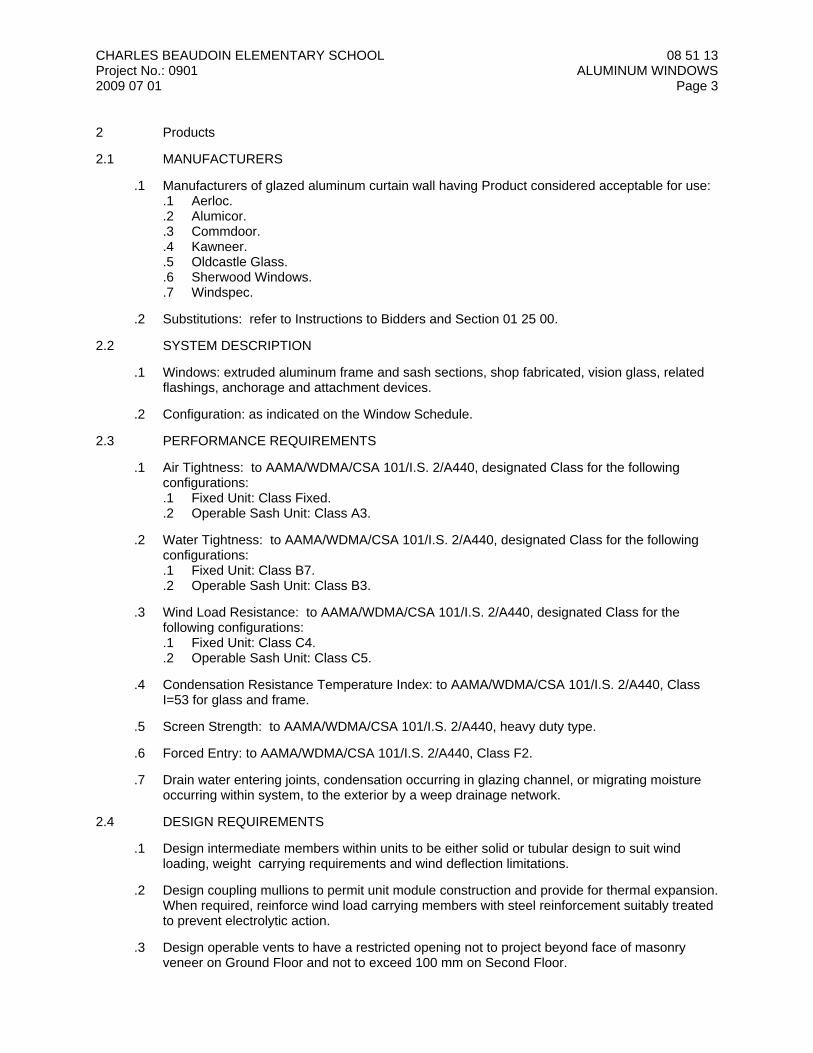
CHARLES BEAUDOIN ELEMENTARY SCHOOLProject No.: 09012009 07 01
08 51 13ALUMINUM WINDOWS
Page 3
2 Products
2.1 MANUFACTURERS
.1 Manufacturers of glazed aluminum curtain wall having Product considered acceptable for use:.1 Aerloc..2 Alumicor..3 Commdoor..4 Kawneer..5 Oldcastle Glass..6 Sherwood Windows..7 Windspec.
.2 Substitutions: refer to Instructions to Bidders and Section 01 25 00.
2.2 SYSTEM DESCRIPTION
.1 Windows: extruded aluminum frame and sash sections, shop fabricated, vision glass, relatedflashings, anchorage and attachment devices.
.2 Configuration: as indicated on the Window Schedule.
2.3 PERFORMANCE REQUIREMENTS
.1 Air Tightness: to AAMA/WDMA/CSA 101/I.S. 2/A440, designated Class for the followingconfigurations:.1 Fixed Unit: Class Fixed..2 Operable Sash Unit: Class A3.
.2 Water Tightness: to AAMA/WDMA/CSA 101/I.S. 2/A440, designated Class for the followingconfigurations:.1 Fixed Unit: Class B7..2 Operable Sash Unit: Class B3.
.3 Wind Load Resistance: to AAMA/WDMA/CSA 101/I.S. 2/A440, designated Class for thefollowing configurations:.1 Fixed Unit: Class C4..2 Operable Sash Unit: Class C5.
.4 Condensation Resistance Temperature Index: to AAMA/WDMA/CSA 101/I.S. 2/A440, ClassI=53 for glass and frame.
.5 Screen Strength: to AAMA/WDMA/CSA 101/I.S. 2/A440, heavy duty type.
.6 Forced Entry: to AAMA/WDMA/CSA 101/I.S. 2/A440, Class F2.
.7 Drain water entering joints, condensation occurring in glazing channel, or migrating moistureoccurring within system, to the exterior by a weep drainage network.
2.4 DESIGN REQUIREMENTS
.1 Design intermediate members within units to be either solid or tubular design to suit windloading, weight carrying requirements and wind deflection limitations.
.2 Design coupling mullions to permit unit module construction and provide for thermal expansion. When required, reinforce wind load carrying members with steel reinforcement suitably treatedto prevent electrolytic action.
.3 Design operable vents to have a restricted opening not to project beyond face of masonryveneer on Ground Floor and not to exceed 100 mm on Second Floor.
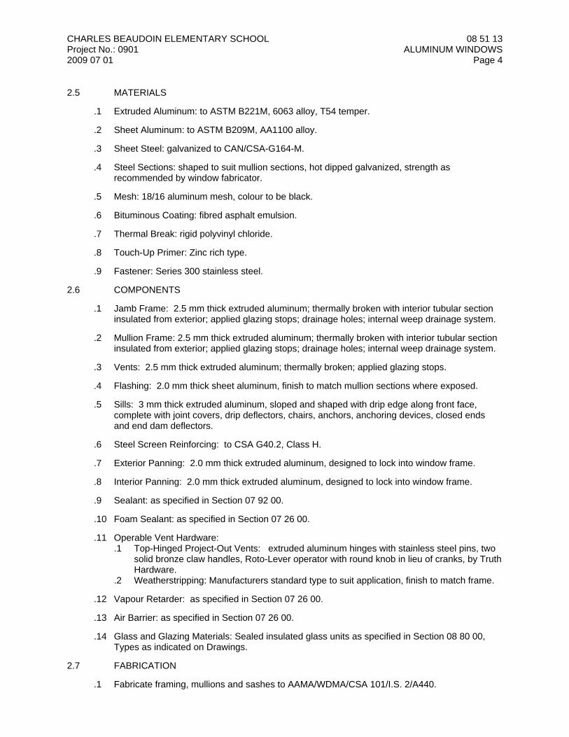
CHARLES BEAUDOIN ELEMENTARY SCHOOLProject No.: 09012009 07 01
08 51 13ALUMINUM WINDOWS
Page 4
2.5 MATERIALS
.1 Extruded Aluminum: to ASTM B221M, 6063 alloy, T54 temper.
.2 Sheet Aluminum: to ASTM B209M, AA1100 alloy.
.3 Sheet Steel: galvanized to CAN/CSA-G164-M.
.4 Steel Sections: shaped to suit mullion sections, hot dipped galvanized, strength asrecommended by window fabricator.
.5 Mesh: 18/16 aluminum mesh, colour to be black.
.6 Bituminous Coating: fibred asphalt emulsion.
.7 Thermal Break: rigid polyvinyl chloride.
.8 Touch-Up Primer: Zinc rich type.
.9 Fastener: Series 300 stainless steel.
2.6 COMPONENTS
.1 Jamb Frame: 2.5 mm thick extruded aluminum; thermally broken with interior tubular sectioninsulated from exterior; applied glazing stops; drainage holes; internal weep drainage system.
.2 Mullion Frame: 2.5 mm thick extruded aluminum; thermally broken with interior tubular sectioninsulated from exterior; applied glazing stops; drainage holes; internal weep drainage system.
.3 Vents: 2.5 mm thick extruded aluminum; thermally broken; applied glazing stops.
.4 Flashing: 2.0 mm thick sheet aluminum, finish to match mullion sections where exposed.
.5 Sills: 3 mm thick extruded aluminum, sloped and shaped with drip edge along front face,complete with joint covers, drip deflectors, chairs, anchors, anchoring devices, closed endsand end dam deflectors.
.6 Steel Screen Reinforcing: to CSA G40.2, Class H.
.7 Exterior Panning: 2.0 mm thick extruded aluminum, designed to lock into window frame.
.8 Interior Panning: 2.0 mm thick extruded aluminum, designed to lock into window frame.
.9 Sealant: as specified in Section 07 92 00.
.10 Foam Sealant: as specified in Section 07 26 00.
.11 Operable Vent Hardware: .1 Top-Hinged Project-Out Vents: extruded aluminum hinges with stainless steel pins, two
solid bronze claw handles, Roto-Lever operator with round knob in lieu of cranks, by TruthHardware.
.2 Weatherstripping: Manufacturers standard type to suit application, finish to match frame.
.12 Vapour Retarder: as specified in Section 07 26 00.
.13 Air Barrier: as specified in Section 07 26 00.
.14 Glass and Glazing Materials: Sealed insulated glass units as specified in Section 08 80 00,Types as indicated on Drawings.
2.7 FABRICATION
.1 Fabricate framing, mullions and sashes to AAMA/WDMA/CSA 101/I.S. 2/A440.
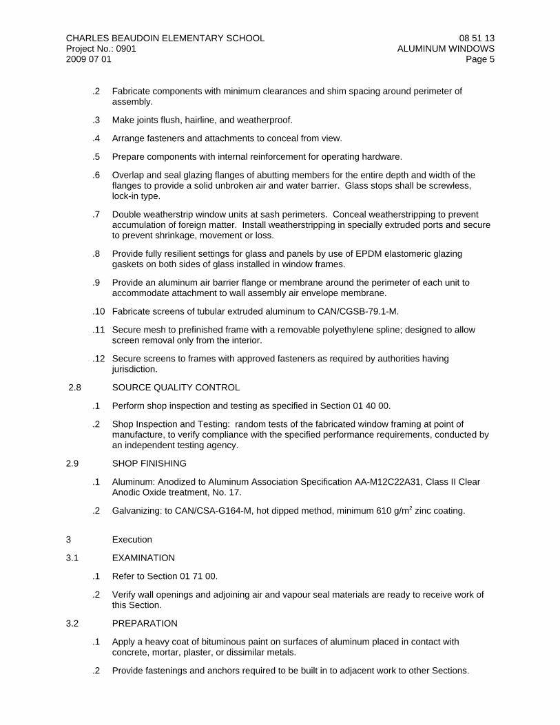
CHARLES BEAUDOIN ELEMENTARY SCHOOLProject No.: 09012009 07 01
08 51 13ALUMINUM WINDOWS
Page 5
.2 Fabricate components with minimum clearances and shim spacing around perimeter ofassembly.
.3 Make joints flush, hairline, and weatherproof.
.4 Arrange fasteners and attachments to conceal from view.
.5 Prepare components with internal reinforcement for operating hardware.
.6 Overlap and seal glazing flanges of abutting members for the entire depth and width of theflanges to provide a solid unbroken air and water barrier. Glass stops shall be screwless,lock-in type.
.7 Double weatherstrip window units at sash perimeters. Conceal weatherstripping to preventaccumulation of foreign matter. Install weatherstripping in specially extruded ports and secureto prevent shrinkage, movement or loss.
.8 Provide fully resilient settings for glass and panels by use of EPDM elastomeric glazinggaskets on both sides of glass installed in window frames.
.9 Provide an aluminum air barrier flange or membrane around the perimeter of each unit toaccommodate attachment to wall assembly air envelope membrane.
.10 Fabricate screens of tubular extruded aluminum to CAN/CGSB-79.1-M.
.11 Secure mesh to prefinished frame with a removable polyethylene spline; designed to allowscreen removal only from the interior.
.12 Secure screens to frames with approved fasteners as required by authorities havingjurisdiction.
2.8 SOURCE QUALITY CONTROL
.1 Perform shop inspection and testing as specified in Section 01 40 00.
.2 Shop Inspection and Testing: random tests of the fabricated window framing at point ofmanufacture, to verify compliance with the specified performance requirements, conducted byan independent testing agency.
2.9 SHOP FINISHING
.1 Aluminum: Anodized to Aluminum Association Specification AA-M12C22A31, Class II ClearAnodic Oxide treatment, No. 17.
.2 Galvanizing: to CAN/CSA-G164-M, hot dipped method, minimum 610 g/m2 zinc coating.
3 Execution
3.1 EXAMINATION
.1 Refer to Section 01 71 00.
.2 Verify wall openings and adjoining air and vapour seal materials are ready to receive work ofthis Section.
3.2 PREPARATION
.1 Apply a heavy coat of bituminous paint on surfaces of aluminum placed in contact withconcrete, mortar, plaster, or dissimilar metals.
.2 Provide fastenings and anchors required to be built in to adjacent work to other Sections.
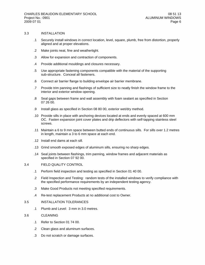
CHARLES BEAUDOIN ELEMENTARY SCHOOLProject No.: 09012009 07 01
08 51 13ALUMINUM WINDOWS
Page 6
3.3 INSTALLATION
.1 Securely install windows in correct location, level, square, plumb, free from distortion, properlyaligned and at proper elevations.
.2 Make joints neat, fine and weathertight.
.3 Allow for expansion and contraction of components.
.4 Provide additional mouldings and closures necessary.
.5 Use appropriate fastening components compatible with the material of the supportingsub-structure. Conceal all fasteners.
.6 Connect air barrier flange to building envelope air barrier membrane.
.7 Provide trim panning and flashings of sufficient size to neatly finish the window frame to theinterior and exterior window opening.
.8 Seal gaps between frame and wall assembly with foam sealant as specified in Section07 26 00.
.9 Install glass as specified in Section 08 80 00, exterior wet/dry method.
.10 Provide sills in place with anchoring devices located at ends and evenly spaced at 600 mmOC. Fasten expansion joint cover plates and drip deflectors with self-tapping stainless steelscrews.
.11 Maintain a 6 to 9 mm space between butted ends of continuous sills. For sills over 1.2 metresin length, maintain a 3 to 6 mm space at each end.
.12 Install end dams at each sill.
.13 Grind smooth exposed edges of aluminum sills, ensuring no sharp edges.
.14 Seal joints between flashings, trim panning, window frames and adjacent materials asspecified in Section 07 92 00.
3.4 FIELD QUALITY CONTROL
.1 Perform field inspection and testing as specified in Section 01 40 00.
.2 Field Inspection and Testing: random tests of the installed windows to verify compliance withthe specified performance requirements by an independent testing agency.
.3 Make Good Products not meeting specified requirements.
.4 Re-test replacement Products at no additional cost to Owner.
3.5 INSTALLATION TOLERANCES
.1 Plumb and Level: 3 mm in 3.0 metres.
3.6 CLEANING
.1 Refer to Section 01 74 00.
.2 Clean glass and aluminum surfaces.
.3 Do not scratch or damage surfaces.

CHARLES BEAUDOIN ELEMENTARY SCHOOLProject No.: 09012009 07 01
08 51 13ALUMINUM WINDOWS
Page 7
.4 Do not remove protective cover from window units until after final cleaning operations havebeen completed.
END OF SECTION
CHARLES BEAUDOIN ELEMENTARY SCHOOLProject No.: 09012009 07 01
08 71 00DOOR HARDWARE
Page 1
1 General
1.1 SECTION INCLUDES
.1 Hardware for doors.
1.2 RELATED SECTIONS
.1 Section 08 11 13 - Hollow Metal Frames.
.2 Section 08 13 13 - Hollow Metal Doors.
.3 Section 08 14 00 - Wood Doors.
1.3 REFERENCES
.1 ANSI/DHI A115.IG-1994: Installation Guide for Doors and Hardware.
.2 Door and Hardware Institute (DHI) - Recommended Locations for Architectural Hardware forStandard Steel Doors and Frames.
.3 Door and Hardware Institute (DHI) - Recommended Locations for Architectural Hardware forFlush Wood Doors.
.4 Door and Hardware Institute (DHI) - Sequence and Format for the Hardware Schedule.
.5 Door and Hardware Institute (DHI) - Keying Systems and Nomenclature.
.6 Door and Hardware Institute (DHI) - Abbreviations and Symbols.
.7 Canadian Steel Door and Frame Manufacturers Association: Manufacturing Standard for SteelDoors and Frames.
.8 Canadian Steel Door and Frame Manufacturers Association: Canadian Fire Labelling Guide forSteel Doors and Frames.
.9 Canadian Steel Door and Frame Manufacturers Association: Canadian Metric Guide for SteelDoors and Frames (Modular Construction).
.10 NFPA 80-2007: Fire Doors and Other Opening Protectives.
1.4 SUBMITTALS
.1 Submit Shop Drawings and Product data as specified in Section 01 33 00.
.2 Shop Drawings: including finish hardware schedule, keying schedule, and wiring diagrams, asfollows:.1 Finish Hardware Schedule, prepared by Architectural Hardware Consultant (AHC), in
vertical format, to DHI Sequence and Format for the Hardware Schedule..2 Keying Schedule: prepared by Architectural Hardware Consultant (AHC), to DHI Keying
Systems and Nomenclature, including all special keying notes and stamping instructions.Do not order locks and cylinders until the key schedule has been accepted by theConsultant.
.3 Wiring Diagrams: a written description of the functional use of all electrical hardware.Include door and frame elevations showing the location of each item of electricalhardware to be installed, including a diagram showing number and size of all conductors.
.3 Product Data: data sheets illustrating each specified piece of finish hardware.
.4 Submit templates to installer prior to installation of hardware commences.
CHARLES BEAUDOIN ELEMENTARY SCHOOLProject No.: 09012009 07 01
08 71 00DOOR HARDWARE
Page 2
1.5 SAMPLES
.1 Submit samples as specified in Section 01 33 00.
.2 Samples: one sample of each hardware item complete with fasteners, clearly labeled withhardware schedule designation and manufacturers’ name and model number.
1.6 CLOSEOUT SUBMITTALS
.1 Submit operating and maintenance data as specified in Section 01 78 00.
.2 Operating and Maintenance Data: including maintenance instructions for each hardware item,catalogue cut sheets and Product data sheets for each Product, parts list for each Product, anupdated copy of the finish hardware schedule illustrating actual Products installed, and a copyof the final keying schedule.
1.7 QUALITY ASSURANCE
.1 Hardware Supplier: company specializing in supplying institutional door hardware with ten (10)years documented experience.
.2 Hardware Supplier Personnel: employ a qualified Architectural Hardware Consultant (AHC) tosupervise the work of this Section.
1.8 PRE-INSTALLATION MEETING
.1 Refer to Section 01 31 00.
.2 Prior to installation of hardware, arrange a meeting between Owner, Contractor, Consultant,manufacturer, hardware Supplier, Architectural Hardware Consultant, and installationSubcontractor to review materials, procedures and coordinate related work.
1.9 REGULATORY REQUIREMENTS
.1 Conform to NFPA requirements for fire rated doors, frames and hardware.
.2 Ensure that all fire exit requirements are met with regard to automatic closers, fusible links,positive latching, direction of travel, etc.
1.10 DELIVERY, STORAGE AND HANDLING
.1 Refer to Section 01 60 00.
.2 Package hardware separately for each opening in a package which contains all the hardwarefor that opening and is designated with applicable heading number, door number, and key-setsymbol.
.3 Store Products in a clean, dry and secure area, on adequate shelving to permit organization soitem numbers are readily visible.
.4 Supply Products complete with keys, templates and installation instructions, together with allrequired screws, expansion shields, anchors, jigs and other related accessories for satisfactoryattachment and installation of hardware.
1.11 WARRANTY
.1 Submit manufacturers' extended warranties for each of the following items, as follows:.1 Butt Hinges: Lifetime,.2 Pivot Sets: 2 years,.3 Locks: 7 years,.4 Keypad Locks: 1 year,.5 Exit Devices: 3 years,.6 Door Closers - Mechanical: 10 years,
CHARLES BEAUDOIN ELEMENTARY SCHOOLProject No.: 09012009 07 01
08 71 00DOOR HARDWARE
Page 3
.7 Door Operators - Electro Mechanical: 2 years,
.8 Door Hold-Open Devices - Electro Mechanical: 2 years,
.9 Overhead Stops and Holders: 1 year,
.10 Floor and Wall Stops: 1 year,
.11 Electric Strikes, Key Switches and Power Supplies: 1 year, and
.12 Electromagnetic Lock Coils: Lifetime.
1.12 EXTRA MATERIALS
.1 Supply extra materials as specified in Section 01 78 00.
.2 Extra Materials: clearly labeled to identify type of hardware, manufacturer name, modelnumber, and finish; for each of the following:.1 ten key lock cylinders for each master keyed group..2 three installation tools for passage sets, locksets and privacy sets.
2 Products
2.1 HINGES
.1 Butt Hinges: concealed bearing hinges for all doors with door closers, non-ferrous with non-removable pins for exterior out-swing doors; 127 mm high hinges where door width exceeds915 mm; supply two hinges for doors up to 1,525 mm high and an additional hinge for each760 mm or fraction thereof in door height.
.2 Continuous Hinges: full height, knuckle type with nylon bearings between each knuckle; steelfor interior applications and stainless steel for exterior applications.
2.2 LOCKS AND LATCHSETS
.1 Locks: supplied from factory with appropriate handing; as follows:.1 Cylindrical Series: heavy duty cylindrical type, with 69 mm backset supplied with a 13 mm
throw latch bolt; chassis to accommodate standard 161 cylindrical lock prep for 45 mmthick doors.
.2 Mortise Series: mortise type with three piece, bevelled, stainless steel latch bolts with19 mm throw and equipped with an anti-friction latch; chassis designed to accommodateANSI standard mortise lock prep with a 69 mm nominal backset for 45 mm thick doors.
.3 Automatic Deadbolts: stainless steel, 25 mm throw; 31 mm high, 16 mm thick;automatically project when door is in closed position.
.4 Unit Lock Series: heavy duty unit type, solid cast stainless steel latch assembly with a 13mm throw deadlocking latch bolt and a 69 mm backset; secured with two stainless steelplates, integrated and through-bolted by the unit lock escutcheons for 45 mm thick doors.
.5 Levers: outside and inside levers operating independently of each other; use patentedclutch mechanism to deter vandalism and maximize durability; designed not to allow latchbolt retraction from secure side while allowing emergency egress.
.6 Function: Classroom and Storeroom function, where outside lever is normally locked andinside lever is always free. Unit may be momentarily unlocked with approved Normalaccess credential, and may be maintained in an unlocked position by using a toggleaccess credential.
.7 Override: emergency mechanical key override utilizing 31 mm mortise cylinder withstandard straight cam.
2.3 KEYING
.1 Key exterior doors to Owner’s existing system.
.2 Provide new factory GMK or MK system as approved by Owner.
.3 Each system to be construction master keyed (CMK), and supplied complete with three (3)keys per lock, five (5) master keys or grand master keys (GMK), ten (10) construction keys.
CHARLES BEAUDOIN ELEMENTARY SCHOOLProject No.: 09012009 07 01
08 71 00DOOR HARDWARE
Page 4
.4 Provide visual key control (VKC) on the face of each cylinder and on all change keys.
2.4 EXIT DEVICES
.1 Exit Devices: low profile push pad style devices; exterior trim of same trim design as locksets.
.2 Exit hardware must have the correct life safety or fire rated labels attached to the active case.
.3 Ensure actuating push pad covers one-half of door opening.
.4 Provide dead latching bolts on exit devices for exterior doors to ensure tamper proof security.
.5 Provide non-rated devices with key cylinder dogging operation.
.6 Where pairs of doors are scheduled to receive two vertical rod exit devices, ensure no overlapping astragal is used by the door manufacturer.
.7 Install exit devices with a gap of 25 mm at the end of the push bar to prevent having fingerspinched between the device and the frame.
2.5 DOOR CLOSERS
.1 Door Closers: full adjustment features including back check, general speed, and latch speedcontrol.
.2 Provide interior door closers with reduced opening force spring power to meet the barrier freerequirement of 22N.
.3 Locate surface mounted door closers on the room side of the door whenever possible or asdirected by the Consultant.
.4 Provide mounting plates necessary for mounting closers on special door and frame conditions.
.5 Provide full body covers on door closers, to match specified finishes.
.6 Stop closers will only be accepted if the stop includes a coil spring mechanism.
.7 Doors located in stairs and other interior high-traffic locations shall be supplied with a separatedelay-action valve to slow the closing cycle and reduce the over-all door use. Delay-actiondoor closers must have a pressure release valve if the door is pulled closed.
2.6 AUTOMATIC DOOR OPERATORS
.1 Automatic Door Operators: include hydraulic door control features including back check andlatch speed.
.2 Connect wire runs and related releasing hardware, such as electric strikes.
.3 Provide activating switches as scheduled.
2.7 PULLS AND PLATES
.1 Pulls: flat plate hospital finger pulls, 150 mm wide and 200 mm high; mounted with spannerhead security screws. When installed on doors with key cylinders, provide a cylinder cut out onthe pull plate.
.2 Kick Plates, Push Plates, and Bumper Plates: 1.27 mm thick, with bevelled sides and roundedcorners with no sharp edges; c/w either tape mounting or counter sunk screw holes; Providekickplates in widths as follows:.1 Single Doors: door width less 38 mm, and.2 Paired Double Doors: door width less 25 mm.
CHARLES BEAUDOIN ELEMENTARY SCHOOLProject No.: 09012009 07 01
08 71 00DOOR HARDWARE
Page 5
2.8 DOOR STOPS AND HOLDERS
.1 Wall stops are only to be used on proper wall conditions such as block or masonry.
.2 Provide floor stops with sufficient height to suit the floor condition or undercut of doors.
.3 Overhead stops and holders will be surface mounted unless there is a conflict with doorclosers or other hardware. Provide door stays with friction action in locations that do not havedoor closers. Install all overhead stops and holders for 90 degree stop, unless otherwisespecified.
.4 Electronic Door Holder: to suit the specified voltage and connected to building fire alarmsystem to release the door when signalled.
2.9 DOOR SEALS
.1 Perimeter Seals: sufficient to fully cover gaps between door, frame and floor condition to sealagainst weather, sound, or smoke.
.2 Frame Gasket: pile type; ribbed extruded housing to prevent distortion during installation.
.3 Door Bottoms: heavy-duty type, with an adjustment screw to ensure proper contact with floor;c/w correct drop insert to accommodate carpet flooring.
.4 Thresholds: designed to ensure door bottom makes full contact; thermally broken for allexterior door openings.
2.10 SHOP FINISHES
.1 Provide BHMA 626 - Brushed Chrome finish unless specified otherwise.
.2 Other BHMA finishes are as follows:.1 Hinges: 630 - satin stainless steel..2 Pivots: 689 - powder coat aluminum..3 Door Closer: 689 - powder coat aluminum..4 Door Pulls: 630 - satin stainless steel..5 Protective Plate: 630 - satin stainless steel..6 Overhead Door Stops and Holders: 630 - satin stainless steel..7 Thresholds: 628 - anodized aluminum..8 Weatherstrip: 628 - anodized aluminum..9 Signage: BLK - black plastic..10 Mullions: 628 - anodized aluminum..11 Key Switches: 630 - satin stainless steel..12 Electric Strikes: 630 - satin stainless steel..13 Magnetic Locks: 628 - anodized aluminum.
3 Execution
3.1 EXAMINATION
.1 Refer to Section 01 71 00.
.2 Verify that door and frame components are ready to receive work and dimensions are asindicated on the shop drawings and schedules.
.3 Verify that power supply of 120 volts, 20 ampere, three phase, 60 Hertz is available to poweroperated devices.
CHARLES BEAUDOIN ELEMENTARY SCHOOLProject No.: 09012009 07 01
08 71 00DOOR HARDWARE
Page 6
3.2 INSTALLATION
.1 Install hardware to ANSI/DHI A115.IG and in accordance with manufacturers' installationguidelines.
.2 Use templates provided by hardware manufacturer.
.3 Provide routing or mortising for hinges and other items required to be mortised or rebated orotherwise housed within material.
.4 Install hardware at mounting heights specified in the manufacturers' templates or as indicatedin hardware schedule.
.5 Install hardware using only manufacturer-supplied and -approved fasteners, in strictaccordance with manufacturers' published installation instructions. Provide suitable security-type fasteners as specified in the hardware sets.
.6 Ensure locksets, latchsets and deadbolts are of the correct hand before installation to ensurethat the cylinder is in the correct position. Handing is part of installation procedure.
.7 Ensure exit devices are of the correct hand and adjust device cam for proper outside trimfunction prior to installation. Handing is part of installation procedure.
.8 Install head seal prior to installation of “PA”-parallel arm mounted door closers and push sidemounted door stops and holders.
.9 Counter sink through-bolt of door pull under push plate during installation.
.10 Mount closers, automatic operators and hold-open devices with through bolts, as indicated inthe finish hardware schedule. Install closers and exit devices on wood doors with through-boltstyle fasteners.
.11 Secure thresholds with machine screws and anchors.
3.3 FIELD QUALITY CONTROL
.1 Examine all hardware after it has been installed and notify Consultant of any cases where ithas been improperly installed, is defective or does not conform to the Contract Documents.
.2 All work shall be of high standard to the approval of the Consultant.
3.4 ADJUSTING
.1 Replace Products exhibiting scratched or damaged surfaces.
.2 Properly tighten fasteners and ensure that fasteners are installed to the full required com-plement.
.3 Adjustment is inclusive of spring power, closing speed, latching speed and back-check at thetime of installation.
.4 Adjust delayed-action door operators and closers to forty-second delay to accommodatebarrier-free access. Time period to be approved by Owner.
3.5 DEMONSTRATION
.1 Demonstrate operation and maintenance of hardware items, including proper use, servicing,adjusting and lubrication procedures, as specified in Section 01 79 00.

CHARLES BEAUDOIN ELEMENTARY SCHOOLProject No.: 09012009 07 01
08 71 00DOOR HARDWARE
Page 7
3.6 PROTECTION
.1 Refer to Section 01 76 00.
.2 Cover surfaces with removable protective film until Substantial Performance of the Work.
END OF SECTION
CHARLES BEAUDOIN ELEMENTARY SCHOOLProject No.: 09012009 07 01
08 80 00GLAZING
Page 1
1 General
1.1 SECTION INCLUDES
.1 Glass and glazing.
1.2 RELATED SECTIONS
.1 Section 07 21 00 - Thermal Insulation: spandrel panel insulation.
.2 Section 07 92 00 - Joint Sealants: glazing sealants.
.3 Section 08 11 13 - Hollow Metal Frames: site-glazed hollow metal frames.
.4 Section 08 13 13 - Hollow Metal Doors: site-glazed hollow metal doors.
.5 Section 08 14 00 - Wood Doors: site-glazed wood doors.
.6 Section 08 44 13 - Glazed Aluminum Curtain Wall: site-glazed curtain walls.
.7 Section 08 51 13 - Aluminum Windows: site-glazed aluminum windows.
.8 Section 10 28 13 - Toilet Accessories: framed mirrors.
1.3 REFERENCES
.1 IGMAC (Insulated Glass Manufacturers Association of Canada) - Quality StandardSpecification.
.2 FGMA (Fixed Glass Manufacturers Association) - Glazing Manual and Glazing SealingSystems Manual.
.3 CAN/CGSB-12.1-M90: Tempered or Laminated Safety Glass.
.4 CAN/CGSB-12.2-M91: Glass, Sheet, Flat, Clear.
.5 CAN/CGSB-12.3-M91: Glass, Polished Plate or Float, Flat, Clear.
.6 CAN/CGSB-12.5-M86: Mirrors, Silvered.
.7 CAN/CGSB-12.8-97: Insulating Glass Units.
.8 CAN/CGSB-12.10-M76: Glass, Light and Heat Reflecting.
.9 CAN/CGSB-12.11-M90: Wired Safety Glass.
1.4 SYSTEM DESCRIPTION
.1 Glass and glazing materials of this Section shall provide continuity of building enclosure vapourand air barrier.
.2 Size of glass to withstand dead loads and positive and negative live loads acting normal toplane of glass.
.3 Limit glass deflection to 1/200 or flexure limit of glass with full recovery of glazing materials,whichever is less.
1.5 SUBMITTALS
.1 Submit Product data as specified in Section 01 33 00.
.2 Product Data on Glass Types Specified: Provide structural, physical and environmentalcharacteristics, size limitations, special handling or installation requirements.
CHARLES BEAUDOIN ELEMENTARY SCHOOLProject No.: 09012009 07 01
08 80 00GLAZING
Page 2
1.6 SAMPLES
.1 Submit samples as specified in Section 01 33 00.
.2 Samples: Submit two samples 300 x 300 mm in size, illustrating glass plastic units,colouration and design.
1.7 QUALITY ASSURANCE
.1 Conform to glazing installation methods and quality standards specified in:.1 FGMA Glazing Manual, .2 IGMAC Quality Standard Specification, and.3 IGMAC Glazing Recommendations for Sealed Insulated Glass Units.
.2 Select glazing compounds and sealants in accordance with glass manufacturers' instructions.
1.8 WARRANTY
.1 Submit an extended warranty in accordance with the General Conditions of the Contract.
.2 Extended Warranty: for a period of five years, including coverage for sealed glass units fromseal failure, interpane dusting or misting, and replacement of same.
2 Products
2.1 MANUFACTURERS
.1 Manufacturers of glass having Product considered acceptable for use:.1 AFG Glass Inc..2 Libbey-Owens Ford..3 PPG Industries.4 Guardian Industries Corp.
.2 Substitutions: refer to Instructions to Bidders and Section 01 25 00.
2.2 FLAT GLASS MATERIALS
.1 Float Glass (Type FG-A): to CAN/CGSB-12.3-M; 5 mm thick, glazing quality.
.2 Sheet Glass (Type FG-B): to CAN/CGSB-12.2-M; 3 mm thick, glazing quality.
.3 Tempered Safety Glass (Type FG-C): to CAN/CGSB-12.1-M; clear float glass fully temperedhorizontally to achieve a net strength of not less than 4 to 5 times greater than regularannealed glass; 6 mm thick.
.4 Heat-Strengthened Glass (Type FG-D): to CAN/CGSB-12.1-M; clear float glass heatstrengthened horizontally to achieve a net strength of not less than 2 times greater than regularannealed glass; 6 mm thick unless specified otherwise.
.5 Tinted Glass (Type FG-E): to CAN/CGSB-12.4-M; 6 mm thick, tempered or heat-strengthenedas noted; Light Green tint; eg. PPG Solexia.
.6 Mirrored Glass (Type FG-F): to CAN/CGSB-12.5-M; Type 18 float glass; 6 mm thick minimum;polished edges; sizes as scheduled or noted on Drawings.
.7 Georgian Wired Glass (Type FG-G): to CAN/CGSB-12.11-M, Type 1, Transparent Style 1 -Square pattern; 13 x 13 mm wire mesh size, using 0.45 mm OD steel wire; 6 mm thick.
CHARLES BEAUDOIN ELEMENTARY SCHOOLProject No.: 09012009 07 01
08 80 00GLAZING
Page 3
2.3 SEALED INSULATING GLASS MATERIALS
.1 Sealed Glass Units (Type SG-A): to CAN/CGSB-12.8; double pane with dual seal edge;comprised as follows:.1 Outer Pane: Tinted tempered glass (FG-E);.2 Inner Pane: Clear tempered glass (FG-C); with Low-E coating on #3 surface;.3 Interpane Space: Argon-filled;.4 Overall Thickness: 25 mm;.5 Visible Light Transmittance: 60 percent;.6 Shading Coefficient: 0.41;.7 Visible Light Reflectance: 11 percent;.8 Manufacturer's Name and Product: eg. PPG Solarban 60 (3) Solexia.
2.4 GLASS SPANDREL PANEL MATERIALS
.1 Spandrel Glass Units (Type SP-A): to CAN/CGSB-12.9-M; single pane insulated infill panel;comprised as follows:.1 Outer Pane: 6 mm thick heat-strengthened Clear glass (Type FG-D), with tinted opaque
coating applied to #2 surface, eg. Opaci-Coat 300 by ICD High Performance Coatings,colour as selected by Consultant.
.2 Insulation: curtain wall mineral fibre insulation as specified in Section 07 21 00,completely filling cavity and securely held in place by mechanical fasteners;
.3 Inner Liner: 1.5 mm thick galvanized steel panel, sealed at edges, corners and fasteners.
2.5 GLAZING ACCESSORIES
.1 Dual Seal: polyisobutylene primary seal with a secondary seal comprised of either silicone,butyl, polysulphide or urethane, as recommended by sealed insulating glass unit manufacturerfor each particular glazing application.
.2 Low-E Coating: sputtered coating; eg. PPG Solarban 60 Solar Control Low-E (Sputtered).
.3 Sealant: as specified in Section 07 92 00.
.4 Setting Blocks: neoprene, 80-90 Shore A durometer hardness.
.5 Spacer Shims: neoprene, 50-60 Shore A durometer hardness.
.6 Glazing Tape: preformed butyl compound with integral resilient tube spacing device.
.7 Glazing Splines: resilient polyvinyl chloride extruded shape; black colour.
3 Execution
3.1 EXAMINATION
.1 Refer to Section 01 71 00.
.2 Verify that openings for glazing are correctly sized, within tolerance and clean.
3.2 PREPARATION
.1 Clean contact surfaces with solvent and wipe dry.
.2 Seal porous glazing channels or recesses with substrate compatible primer or sealer.
.3 Prime surfaces scheduled to receive sealant.
CHARLES BEAUDOIN ELEMENTARY SCHOOLProject No.: 09012009 07 01
08 80 00GLAZING
Page 4
3.3 EXTERIOR - WET/DRY METHOD (PREFORMED TAPE AND SEALANT)
.1 Cut glazing tape to length and set against permanent stops, 5 mm below sight line. Sealcorners by butting tape and dabbing with sealant.
.2 Apply heel bead of sealant along intersection of permanent stop with frame ensuring fullperimeter seal between glass and frame to complete the continuity of the air and vapour seal.
.3 Place setting blocks at one-quarter points with edge block no more than 150 mm from corners.
.4 Rest glazing on setting blocks and push against tape and heel bead of sealant with sufficientpressure to attain full contact at perimeter of pane or glass unit.
.5 Install removable stops, with spacer strips inserted between glazing and applied stops, 6 mmbelow sight line.
.6 Place glazing tape on glazing pane or unit with tape flush with sight line.
.7 Fill gap between glazing and stop with sealant to depth equal to bite of frame on glazing, butnot more than 9 mm below sight line.
.8 Apply cap bead of sealant along void between the stop and the glazing, to uniform line, flushwith sight line. Tool or wipe sealant surface smooth.
3.4 INTERIOR - DRY METHOD (TAPE AND TAPE)
.1 Cut glazing tape to length and set against permanent stops, projecting 1.6 mm above sightline.
.2 Place setting blocks at one-third points with edge block no more than 150 mm from corners.
.3 Rest glazing on setting blocks and push against tape for full contact at perimeter of pane orunit.
.4 Place glazing tape on free perimeter of glazing in same manner described above.
.5 Install removable stop without displacement of tape. Exert pressure on tape for full continuouscontact.
.6 Knife trim protruding tape.
3.5 SLIDING GLASS PANELS
.1 Site measure casework openings, and fabricate sliding glass panels to sufficient sizes,including adequate overlaps to accommodate locking devices.
.2 Coordinate necessary clearances and sizes with manufacturer of sliding glass track assemblyspecified in Section 06 40 00.
.3 Drill holes in glass panes as required.
.4 Grind all edges smooth and slightly rounded.
.5 Temper glass after fabrication is complete.
.6 Install sliding glass panels in casework on hardware described in Section 06 40 00. Ensuresmooth operation.
3.6 SHELVES
.1 Polish glass edges prior to installation.
.2 Install shelves in fitments or casework on hardware described in Section 06 40 00.
CHARLES BEAUDOIN ELEMENTARY SCHOOLProject No.: 09012009 07 01
08 80 00GLAZING
Page 5
3.7 CLEANING
.1 Refer to Section 01 74 00.
.2 Remove glazing materials from finish surfaces.
.3 Remove labels after Work is complete.
.4 Clean glass.
END OF SECTION
CHARLES BEAUDOIN ELEMENTARY SCHOOLProject No.: 09012009 07 01
09 21 16GYPSUM BOARD ASSEMBLIES
Page 1
1 General
1.1 SECTION INCLUDES
.1 Metal framing.
.2 Gypsum board.
.3 Cement board.
1.2 RELATED SECTIONS
.1 Section 06 10 00 - Rough Carpentry: wood blocking.
.2 Section 07 21 00 - Thermal Insulation: acoustic insulation.
.3 Section 07 92 00 - Joint Sealants: acoustic sealant.
.4 Section 08 11 13 - Hollow Metal Frames.
.5 Section 08 31 00 - Access Door and Panels.
.6 Section 09 51 23 - Acoustical Tile Ceilings.
.7 Section 09 90 00 - Painting and Coating.
1.3 REFERENCES
.1 ASTM C36/C36M-01: Standard Specification for Gypsum Wallboard.
.2 ASTM C442/C442M-01: Standard Specification for Gypsum Backing Board, GypsumCoreboard, and Gypsum Shaftliner Board.
.3 ASTM C475/C475M-07: Standard Specification for Joint Compound and Joint Tape forFinishing Gypsum Board.
.4 ASTM C514-01: Standard Specification for Nails for the Application of Gypsum Board.
.5 ASTM C645-07b: Standard Specification for Nonstructural Steel Framing Members.
.6 ASTM C840-07: Standard Specification for Application and Finishing of Gypsum Board.
.7 ASTM C954-07: Standard Specification for Steel Drill Screws for the Application of GypsumPanel Products or Metal Plaster Bases to Steel Studs From 0.033 in. (0.84 mm) to 0.112 in.(2.84 mm) in Thickness.
.8 ASTM C1047-99: Standard Specification for Accessories for Gypsum Wallboard and GypsumVeneer Base.
.9 ASTM C1325-99: Standard Specification for Non-Asbestos Fiber-Mat Reinforced CementInterior Substrate Sheets.
.10 ASTM E84-07b: Standard Test Method for Surface Burning Characteristics of BuildingMaterials.
.11 Canadian Gypsum Company: CGC Gypsum Construction Handbook.
.12 CAN/CGSB-71.25-M88: Adhesive, for Bonding Drywall to Wood Framing and Metal Studs.
.13 Underwriters Laboratories of Canada: List of Equipment and Materials.
CHARLES BEAUDOIN ELEMENTARY SCHOOLProject No.: 09012009 07 01
09 21 16GYPSUM BOARD ASSEMBLIES
Page 2
1.4 SUSTAINABLE DESIGN REQUIREMENT
.1 Target Recycled Content for Interior-grade Gypsum Board: minimum 5 percent post-consumerand 90 percent post-industrial.
1.5 QUALITY ASSURANCE
.1 Applicators: company specializing in applying the work of this Section with a minimum of fiveyears documented experience.
2 Products
2.1 MANUFACTURERS
.1 Manufacturers of gypsum board having Product considered acceptable for use:.1 CertainTeed Gypsum, Canada Inc..2 CGC Inc..3 G-P Gypsum Corporation.
.2 Manufacturers of cement board having Product considered acceptable for use:.1 CertainTeed Gypsum, Canada Inc..2 CGC Inc.
.3 Substitutions: refer to Instructions to Bidders and Section 01 25 00.
2.2 MATERIALS
.1 Studs and Tracks: to ASTM C645, 0.5 mm thick galvanized sheet steel, 'C' shape, withserrated faces. Provide knock-outs for electrical trades.
.2 Furring, Framing and Accessories: to ASTM C645, galvanized steel channel sections designedto perform their intended function.
.3 Gypsum Board - Regular (GB-R): to ASTM C36; tapered edges, ivory faced.
.4 Gypsum Board - Fire-Rated (GB-FR): to ASTM C36, Type X; tapered edges, ivory faced, ULClabelled.
.5 Gypsum Board - Backing Board (GB-BB): to ASTM C442; 12.7 mm thick; square edges.
.6 Cement Board (CB): to ASTM C1325; polymer modified concrete core, dual layer of alkali-resistant fibre mesh reinforced faces and edges, tapered rolled edges; thicknesses asindicated on Drawings; eg. Unifix PermaBase Brand Cement Board by CertainTeed Gypsum,Canada Inc.
2.3 ACCESSORIES
.1 Nail Fasteners: galvanized steel; to ASTM C514.
.2 Steel Drill Screws: galvanized steel; to ASTM C954.
.3 Adhesive: to CAN/CGSB-71.25-M.
.4 Joint Materials: to ASTM C475/C475M; reinforcing tape, joint compound, adhesive, water,fasteners.
.5 Corner Beads, Casing Beads, Control Joints and Edge Trim: to ASTM C1047; metal type.
.6 Acoustic Insulation: mineral fibre acoustical batt insulation, as specified in Section 07 21 00.
.7 Sealant: acoustical sealant, as specified in Section 07 92 00.

CHARLES BEAUDOIN ELEMENTARY SCHOOLProject No.: 09012009 07 01
09 21 16GYPSUM BOARD ASSEMBLIES
Page 3
3 Execution
3.1 METAL STUD AND FURRING INSTALLATION
.1 Install stud framing to ASTM C840, and in accordance with manufacturer's instructions.
.2 Metal Stud Spacing: typical 400 mm OC.
.3 Partition Heights: Full height to floor or roof construction above. Install additional bracing forpartitions extending above ceiling.
.4 Erect furring for direct attachment to concrete block walls and concrete walls, ceilings andsoffits.
.5 Install furring as required for fire resistance ratings indicated.
3.2 CEILING FRAMING INSTALLATION
.1 Install ceiling framing to ASTM C840, and in accordance with manufacturer's instructions
.2 Install ceiling framing independent of walls, columns, and above ceiling work.
.3 Laterally brace entire suspension system.
3.3 ACOUSTICAL ACCESSORIES INSTALLATION
.1 Install resilient channels at maximum 600 mm OC.
.2 Place acoustical insulation in partitions tight within spaces, around cut openings, behind andaround electrical and mechanical items within or behind partitions, and tight to items passingthrough partitions.
.3 Install acoustical sealant within partitions in accordance with manufacturer's instructions
3.4 BOARD INSTALLATION
.1 Install wall and ceiling board Products to ASTM C840, and in accordance with manufacturer'sinstructions.
.2 Install boards perpendicular to supports.
.3 Screw fasten boards to furring or framing.
.4 Double Layer Applications: Use gypsum backing board for first layer, place perpendicular toframing or furring members. Place second layer perpendicular to first layer.
.5 Place corner beads at external corners. Place edge trim where gypsum board abuts dissimilarmaterials. Fasten with nail attachment, unless specified otherwise.
.6 Finished work shall be plane and free from all depressions, ready to receive paint finish byothers.
.7 Provide bulkheads where changes of ceiling or height occur. Include all necessary channelframing, etc.
.8 Provide furring necessary to conceal exposed pipes or ducts. Refer to mechanical andelectrical drawings to determine extent of work necessary.
.9 Install access panels when and where directed by affected Subcontractors. Refer to Section08 31 00.
.10 Tape, fill, and sand exposed joints, edges, and corners to produce smooth surface ready toreceive finishes.
CHARLES BEAUDOIN ELEMENTARY SCHOOLProject No.: 09012009 07 01
09 21 16GYPSUM BOARD ASSEMBLIES
Page 4
3.5 CONTROL JOINTS
.1 Provide control joints in accordance with manufacturer's instructions; where indicated onDrawings and where:.1 ceiling, partition or furring abuts a structural element,.2 ceiling, partition or furring abuts dissimilar construction,.3 construction changes within plane of the partition or ceiling,.4 partition or furring run exceeds 9.0 metres,.5 ceiling dimensions exceed 15.0 metres in either direction,.6 wings of "L-", "U-" and "T"-shaped ceiling areas are joined, and.7 expansion or control joints occur in the structural elements of the building.
.2 Break continuity of gypsum board and framing system at control joints.
.3 Provide continuous control joint profile.
3.6 RELIEF JOINTS
.1 Provide relief joints where indicated on the Drawings and where gypsum board assembliesabut dissimilar construction.
.2 Stop gypsum board 6 mm from abutting construction at dissimilar building elements, unlessindicated otherwise.
.3 Provide a thermal break where gypsum board comes into contact with frames. Adhere self-adhering tape to casing bead and compress during installation of gypsum board.
.4 Provide reveal mouldings where gypsum board ceilings meet curved wall surfaces, and whereindicated on the Drawings.
END OF SECTION
CHARLES BEAUDOIN ELEMENTARY SCHOOLProject No.: 09012009 07 01
09 30 00TILINGPage 1
1 General
1.1 SECTION INCLUDES
.1 Tile floors.
.2 Tile walls.
.3 Tile stair treads and risers.
1.2 RELATED SECTIONS
.1 Section 03 35 00 - Concrete Finishing.
.2 Section 03 41 13 - Precast Concrete Hollow-Core Planks.
.3 Section 03 41 23 - Precast Concrete Stairs.
.4 Section 04 22 00 - Concrete Unit Masonry.
.5 Section 09 21 16 - Gypsum Board Assemblies.
1.3 REFERENCES
.1 ANSI A108.4-2005: Ceramic Tile Installed with Water-Resistant Organic Adhesives or Water-Cleanable Tile Setting Epoxy Adhesive.
.2 ANSI A108.5-2005: Ceramic Tile Installed with Dry-Set Portland Cement Mortar or Latex-Portland Cement Mortar.
.3 ANSI A108.10-2005: Installation of Grout in Tilework.
.4 ANSI A118.1-2005: Dry-Set Portland Cement.
.5 ANSI A118.4-2005: Latex-Portland Cement Mortar.
.6 ANSI A118.6-2005: Ceramic Tile Grouts.
.7 ANSI A136.1-2005: Organic Adhesive.
.8 ASTM C144-04: Standard Specification for Aggregate for Masonry Mortar.
.9 ASTM C207-06: Standard Specification for Hydrated Lime.
.10 ASTM C627-93(2007): Standard test Method for Evaluating Ceramic Floor Tile InstallationSystems Using the Robinson-Type Floor Tester.
.11 ASTM C847-06: Standard Specification for Metal Lath.
.12 CAN/CSA-A3001-03: Cementitious Materials for Use in Concrete.
.13 CAN/CGSB-25.20-95: Surface Sealer for Floors.
.14 CAN/CGSB-75.1-M88: Tile, Ceramic.
.15 Terrazzo Tile & Marble Association of Canada (TTMAC): Specification Guide 09 30 00 - TileInstallation Manual 2006-2007.
1.4 DESIGN REQUIREMENTS
.1 Traffic Level Performance: floor tiles to meet Moderate Class, passing ASTM C627, cycles 1through 10, as described in TTMAC Specification Guide 09 30 00.
CHARLES BEAUDOIN ELEMENTARY SCHOOLProject No.: 09012009 07 01
09 30 00TILINGPage 2
1.5 SUSTAINABLE DESIGN REQUIREMENTS
.1 Target Recycled Content for Ceramic Wall Tile: minimum 0 percent post-consumer and35 percent post-industrial.
1.6 SAMPLES
.1 Submit samples as specified in Section 01 33 00.
.2 Verification Samples: 300 x 300 mm size panel c/w approved grout colour; mounted to 19 mmthick plywood backer.
1.7 CLOSEOUT SUBMITTALS
.1 Submit closeout submittals as specified in Section 01 78 00.
.2 Closeout Submittals: duplicate copies of the latest edition of the TTMAC Maintenance Guide.
1.8 QUALITY ASSURANCE
.1 Employ skilled mechanics trained and experienced in tile work, and registered as members ofthe Terrazzo Tile and Marble Association of Canada.
.2 Install Products to TTMAC Specification Guide 09 30 00.
1.9 MOCK-UP
.1 Construct a jobsite mock-up as specified in Section 01 40 00.
.2 Mock-Up: illustrating typical wall and floor tile applications for each tile type and colour..1 Locate mock-ups in areas designated by Consultant..2 Incorporate borders or accent tiles as designated by Consultant..3 Illustrate transitions to adjacent materials. Include proposed transition strips..4 Accepted mock-ups will remain as part of the completed Work. Protect from damage or
disfigurement until Substantial Performance of the Work.
1.10 ENVIRONMENTAL CONDITIONS
.1 Do not install tiles at temperatures less than 12 degrees Celsius.
.2 Maintain temperatures at or above 12 degrees Celsius until cementitious materials have fullycured.
1.11 DELIVERY STORAGE AND HANDLING
.1 Refer to Section 01 60 00.
.2 Store Products in a dry area, protected from freezing, staining and damage.
.3 Store cementitious materials on a dry surface.
1.12 EXTRA MATERIALS
.1 Supply extra materials as specified in Section 01 78 00.
.2 Extra Materials: 4 m2 or 2 percent, whichever is the greater, of each type and colour of tile;clearly marked to identify:.1 Manufacturer's name,.2 Product's name,.3 Product colour and pattern.
.3 Package tile products neatly in original containers, to prevent damage.
CHARLES BEAUDOIN ELEMENTARY SCHOOLProject No.: 09012009 07 01
09 30 00TILINGPage 3
2 Products
2.1 MANUFACTURERS
.1 Manufacturers of grout and adhesive having Product considered acceptable for use:.1 Realta Mapei..2 Laticrete..3 Flextile.
.2 Manufacturers of tile setting accessories having Product considered acceptable for use:.1 Schlüter Systems (Canada) Inc.; as distributed by Centura.
.3 Substitutions: refer to Instructions to Bidders and Section 01 25 00.
2.2 TILE MATERIALS
.1 Porcelain Floor Tile (CT-1): 300 x 300 mm size; 9 mm thick; honed porcelain; toCAN/CGSB-75.1-M, Type 4, Class MR2; Dotti Series Speckled Granati as distributed byCentura Floor and Wall Fashions or similar by Savoia Canada Inc.; premium colours asselected by Consultant, up to a maximum of 4 colours.
.2 Porcelain Non-Slip Floor Tile (CT-2): 300 x 300 mm size; 9 mm thick; to CAN/CGSB-75.1-M,Type 1, Class MR2; Dotti Series as distributed by Centura Floor and Wall Fashions or similarby Savoia Canada Inc., premium colours as selected by Consultant, up to a maximum of 2colours.
.3 Porcelain Tile Base: coved; cut from porcelain floor tile specified above, 100 mm high, 300 mmlong.
2.3 MORTAR MATERIALS
.1 Portland Cement: to CAN/CSA-A3001, Type GU.
.2 Hydrated Lime: to ASTM C207, Type N-Normal.
.3 Sand: to ASTM C144, passing 16 mesh.
.4 Dry-Set Portland Cement Mortar: to ANSI A118.1.
.5 Latex-Portland Cement Mortar: to ANSI A118.4.
2.4 GROUT MATERIALS
.1 Floor Grout: to ANSI A118.6; polymer-modified sanded grout; eg. Mapei Keracolor S, multiplecolours up to maximum of 2 colours per room, as selected by Consultant.
.2 Base and Wall Grout: to ANSI A118.6; polymer-modified unsanded grout; eg. Mapei KeracolorU, multiple colours up to maximum of 2 colours per room, as selected by Consultant.
2.5 ACCESSORIES
.1 Metal Lath: galvanized type, 1.4 kg/m2, to ASTM C847.
.2 Reinforcing Mesh: 50 x 50 mm size; 1.6 mm thick steel wire mesh; welded fabric, galvanized.
.3 Tape: 50 mm fibre mesh tape, as recommended by backer board manufacturer.
.4 Organic Adhesive: to ANSI A136.1, Type 1 for wet areas and Type 2 for dry areas.
.5 Latex Additive: formulated for use in portland cement mortars and grout.
.6 Water: clean, cold and potable.
.7 Joint Sealant: as specified in Section 07 92 00.
CHARLES BEAUDOIN ELEMENTARY SCHOOLProject No.: 09012009 07 01
09 30 00TILINGPage 4
.8 Sealer: to CAN/CGSB-25.20, Type 1 - Penetrating; as recommended by tile manufacturer.
2.6 MANUFACTURED COMPONENTS AND ACCESSORIES
.1 Tile Edge and Transition Strips: Roll-formed stainless steel edge strips, 3 mm wide at topedge; height as indicated; with integral perforated anchoring leg for setting the strip into thesetting material; height as required to suit application; eg. Schlüter®-SCHIENE-E.
.2 Tile Transition Joint Strips: Roll-formed stainless steel transition strips; profile and height asindicated; with integral perforated anchoring leg for setting the strip into the setting material;sloped transition and decorative edge strip for transition from tile to lower finish; eg. Schlüter®-RENO-EU.
.3 Tile Expansion and Control Joints for Thin-Set Applications: Roll formed stainless steel profilesjoined by a soft CPE movement joint material, with integral perforated anchoring legs forsetting the joint into the setting bed; height as required to suit application; insert colour asselected by Consultant from manufacturer’s standard range; eg. Schlüter®-DILEX-EKSN.
.4 Tile Decorative Wall Corner Trim: Roll formed stainless steel profile, decorative outside wallcorner trim, with integral perforated anchoring leg for setting the strip into the setting material;height and material/finish as indicated; height as required; pre-formed inside corners, pre-formed outside corners; colour to match profile colour; eg. Schlüter®-RONDEC-E.
.5 Uncoupling Membrane: rigid polyethylene membrane with 4 mm high corrugated ribs cut backin dovetail configuration; scrim laminated to underside; Schlüter®-DITRA.
2.7 MIXES
.1 Scratch Coat (by volume): 1 part Portland cement, 4 parts sand, and latex additive whererequired by TTMAC Detail. Premixed mortar may be used per manufacturer’s instructions. Adjust water volume depending on moisture content of sand to obtain consistency andworkability.
.2 Slurry Bond Coat: mix Portland cement and water to a creamy paste consistency. Includelatex additive where required by TTMAC Detail.
.3 Mortar Bed for Walls (by volume): 1 part Portland cement, 4 parts sand, and latex additivewhere required by TTMAC Detail. Premixed mortar may be used per manufacturer’sinstructions. Adjust water volume depending on moisture content of sand to obtainconsistency and workability.
.4 Levelling Coat (by volume): 1 part Portland cement, 4 parts sand, and latex additive whererequired by TTMAC Detail. Premixed mortar may be used per manufacturer’s instructions.
.5 Mortar Bed for Floors: 1 part Portland cement, 4 parts sand, and latex additive where requiredby TTMAC Detail. Premixed mortar may be used per manufacturer’s instructions. Adjustwater volume depending on moisture content of sand to obtain consistency and workability.When mixed with water the mortar bed shall be of such a consistency and workability that willallow maximum compaction during tamping of the mortar bed, and achieve a minimumcompressive strength of 21 MPa after 28 days.
2.8 MIXING
.1 Mix commercial mortars and grouts strictly in accordance with manufacturer'srecommendations.
3 Execution
3.1 EXAMINATION
.1 Refer to Section 01 71 00.

CHARLES BEAUDOIN ELEMENTARY SCHOOLProject No.: 09012009 07 01
09 30 00TILINGPage 5
.2 Ensure substrate surfaces are clean, dimensionally stable, cured and free of contaminantssuch as oil, sealers and curing compounds.
.3 Ensure that concrete has been allowed to cure for a minimum of 28 days.
.4 Ensure concrete floors have not been treated with proprietary curing compounds.
.5 Ensure concrete floors scheduled to receive thin-set applied tile or cleavage membranes aresteel trowelled to a fine broom finish. Ensure concrete slabs have been finished with amaximum permissible variation of 3 mm in 3 metres from the required plane and not more than1.5 mm in 305 mm when measured from high points in the surface.
.6 Ensure concrete floors scheduled to receive tile applied over a bonded mortar bed have beenscreed finished. Verify substrate surface variation does not exceed 6 mm in 3 metres.
3.2 PREPARATION
.1 Protect surrounding work from damage or disfiguration.
.2 Thoroughly clean existing surfaces which are to receive tile finish to ensure the removal of allgrease, oil or dust film.
.3 Apply a latex modified cementitious levelling coat wherever a slight substrate irregularity exists. Limit levelling coat thickness to less than 8 mm where thin-set tile methods are to be used. Install a levelling coat in excess of 8 mm when setting tile with a mortar bed method.
.4 Install uncoupling membrane over structural concrete slab. If an uncoupling membrane isbeing applied over a rough surface, apply a 6 mm thick sand-bed under the membrane.
.5 Cover backer board joints with fibre mesh tape set in latex-Portland cement mortar.
3.3 INSTALLATION
.1 Install Products to TTMAC Specification Guide 09 30 00, as scheduled below.
.2 Apply tile using water-resistant organic adhesives to ANSI A108.4.
.3 Apply tile in dry-set Portland cement mortar or latex-Portland cement mortar beds toANSI A108.5.
.4 Fit tile units around corners, fitments, fixtures, drains and other built-in objects to maintainuniform joint appearance.
.5 Make cut edges smooth, even and free from chipping. Do not split tile.
.6 Lay out tiles so that perimeter and cut tiles are no less than half size. Refer to Drawings forspecific floor patterns.
.7 Set tiles in place while bond coat is wet and tacky, prior to skinning over. Slide tile back andforth to ensure a proper bond and level surface. Avoid lippage.
.8 Clean backs of tiles and back butter tiles to ensure a 95 percent bond coverage.
.9 Clean excess mortar from surface prior to final set.
.10 Sound tiles after setting materials have cured and replace hollow sounding tile before grouting.
.11 Exterior Surfaces and Wet Areas (Thin Set Method).1 Notch adhesive in straight lines, backbutter tile and set on freshly trowelled thin-set
mortar..2 Move tile back and forth perpendicular to notches.
CHARLES BEAUDOIN ELEMENTARY SCHOOLProject No.: 09012009 07 01
09 30 00TILINGPage 6
.12 Ungauged Slate, Marble, Stone and Large Ceramics.1 Immediately prior to setting, backbutter tile through a push box or box screed to achieve a
uniform thickness of tile and mortar.
.13 Keep two-thirds the depth of grout joints free of setting material.
3.4 MOVEMENT JOINTS
.1 Install control joints and expansion joints in tile work in accordance with TTMAC Detail 301MJ.
.2 Keep all control and expansion joints free of setting materials.
3.5 TILE-SETTING ACCESSORIES INSTALLATION
.1 Install tile-setting accessories in continuous lengths, to level straight lines by pressing theperforated anchoring leg of the accessory solidly into the tile setting adhesive.
.2 Butt ends of units tightly together with hairline joint. Trowel an additional layer of tile settingmaterial over the anchored leg of the accessory prior to placement of tiles.
.3 Unless specified otherwise, solidly embed tiles over anchoring leg of installed trim with surfaceof tile flush with top of tile-setting accessories.
.4 Leave 3 mm joint between tile and tile-setting accessories for filling with grout.
.5 Install pre-formed end-caps and trim at all inside corners, outside corners, 3-way corners, andends.
.6 Expansion and Control Joints: Solidly embed tiles over installed edge strips with joint surfaceeither flush with top of joint or 1 mm below top of tile.
3.6 GROUTING
.1 Allow proper setting time prior to grouting.
.2 Pre-seal tiles requiring protection from grout staining.
.3 Apply cementitious grout into joints to ensure dense finish. Conform to manufacturer'srecommendations and ANSI A108.10.
.4 Force grout into joints to ensure dense finish.
.5 Remove excess and polish with clean cloths.
3.7 FIELD QUALITY CONTROL
.1 Inspect completed work and replace broken, cracked, or damaged tile.
3.8 TOLERANCES
.1 Level tiles to conform to a 1 mm tolerance over a 3 mm joint.
3.9 CLEANING
.1 Refer to Section 01 74 00.
.2 Apply floor sealer in accordance with manufacturer's instructions.
3.10 PROTECTION
.1 Refer to Section 01 76 00.
.2 Protect finished areas from traffic until setting materials have sufficiently cured.
CHARLES BEAUDOIN ELEMENTARY SCHOOLProject No.: 09012009 07 01
09 30 00TILINGPage 7
.3 Protect grouted areas from traffic for 24 hours after grouting.
.4 Provide protective covering until Owner occupancy.
.5 Protect wall tiles and bases from impact, vibration, heavy hammering on adjacent and oppositewalls for at least 14 days after installation.
3.11 SCHEDULE
.1 Tile Installed Over Masonry or Concrete Walls - Thin-Set Method: TTMAC Detail 303W.
.2 Tile Installed On Cementitious Backer Units (CBU) - Thin-Set Method (Wet/Dry Areas andExterior Use): TTMAC Detail 305W (A).
.3 Tile Installed Hollow-Core Concrete Planks Over Mortar Bed With Cleavage Membrane:TTMAC Detail 309F.
.4 Tile Bonded to Concrete Slab - Thin-Set Method (Interior/Exterior): TTMAC Detail 311F (A).
.5 Tile Installed on Interior/Exterior Stairs (Precast Concrete): TTMAC Detail 318S (E).
END OF SECTION
CHARLES BEAUDOIN ELEMENTARY SCHOOLProject No.: 09012009 07 01
09 51 23ACOUSTICAL TILE CEILINGS
Page 1
1 General
1.1 SECTION INCLUDES
.1 Suspended metal grid ceiling system.
.2 Acoustic lay-in tiles.
1.2 RELATED SECTIONS
.1 Section 09 21 16 - Gypsum Board Assemblies: gypsum board ceilings.
1.3 REFERENCES
.1 ASTM C635/C635M-07: Standard Specification for the Manufacture, Performance, and Testingof Metal Suspension Systems for Acoustical Tile and Lay-in Panel Ceilings.
.2 ASTM C636-04: Standard Practice for Installation of Metal Ceiling Suspension Systems forAcoustical Tile and Lay-In Panels.
.3 ASTM E84-07b: Standard Test Method for Surface Burning Characteristics of BuildingMaterials.
.4 ASTM E1264-98: Standard Classification for Acoustical Ceiling Products.
.5 Ceiling & Interior Systems Construction Association (CISCA): Ceiling Systems Handbook.
.6 Underwriters Laboratories of Canada: List of Equipment and Materials.
1.4 SUSTAINABLE DESIGN REQUIREMENTS
.1 Target Recycled Content for Acoustical Lay-in Tile: minimum 5 percent post-consumer and40 percent post-industrial.
.2 Target Recycled Content for Suspended Tile Ceiling Grid: minimum 15 percent post-consumerand 50 percent post-industrial.
1.5 SAMPLES
.1 Submit samples as specified in Section 01 33 00.
.2 Samples: one for each type of acoustic lay-in tile specified, 140 x 290 mm size, indicatingtexture, pattern, colour and edge detail.
1.6 QUALITY ASSURANCE
.1 Installers: company specializing in installing or applying the work of this Section with aminimum of three years documented experience.
1.7 DELIVERY, STORAGE AND HANDLING
.1 Refer to Section 01 60 00.
.2 Deliver Products undamaged original containers.
.3 Store Products in warm, dry area.
1.8 EXTRA MATERIALS
.1 Supply extra materials as specified in Section 01 78 00.
CHARLES BEAUDOIN ELEMENTARY SCHOOLProject No.: 09012009 07 01
09 51 23ACOUSTICAL TILE CEILINGS
Page 2
.2 Extra Materials: minimum two full bundles for each lay-in tile ceiling Product, colour andpattern; clearly marked to identify:.1 Manufacturer's name,.2 Product's name,.3 Product colour and pattern.
.3 Store bundles in original undamaged packages, in a warm, dry area.
2 Products
2.1 MANUFACTURERS
.1 Manufacturers of metal suspension systems who have Product considered acceptable for use:.1 Armstrong World Industries..2 Bailey Metal Products Limited..3 CGC Inc..4 Chicago Metallic Corporation.
.2 Manufacturers of acoustic lay-in tile who have Product considered acceptable for use:.1 Armstrong World Industries..2 CertainTeed..3 CGC Inc.
.3 Substitutions: refer to Instructions to Bidders and Section 01 25 00.
2.2 SUSPENSION SYSTEM MATERIALS
.1 Non-Rated Suspension Grid: to ASTM C635/C635M, commercial quality, cold rolled steel,heavy duty, non-fire rated, main tees and cross tees with exposed 24 mm T-shape, 38 mmhigh flange; die cut and interlocking components; shop finished.
.2 Accessories: stabilizer bars, clips, splices, edge mouldings, and hold down clips required forsuspended grid system.
.3 Support Channels and Hangers: galvanized steel, to rigidly secure ceiling system withmaximum deflection of 1/360.
.4 Acoustic Ceiling Tile: wet-formed mineral fiber non-sagging lay-in tile, to ASTM E1264,Type III, Form 2, Pattern C E; as follows:.1 Size: 610 x 1 220 mm size..2 Thickness: 15 mm..3 Pattern: medium texture, non-directional fissured..4 Edge: square edge..5 Finish: factory applied vinyl latex coated surface, White colour. .6 Fire Resistance: fire resistive for use in UL rated assemblies..7 Weight: 4.882 kg/m2;.8 Noise Reduction Coefficient: 0.55..9 Light Reflectance: 0.84..10 Manufacturer and Product Name: eg. Fine Fissured 1830 by Armstrong World Industries.
.5 Eggcrate Panel: 13 mm thick, acrylic, White colour.
2.3 SHOP FINISHING
.1 Galvanizing: hot dipped method, minimum Z275 coating.
.2 Suspension Grid: baked enamel, White colour.
CHARLES BEAUDOIN ELEMENTARY SCHOOLProject No.: 09012009 07 01
09 51 23ACOUSTICAL TILE CEILINGS
Page 3
3 Execution
3.1 EXAMINATION
.1 Refer to Section 01 71 00.
.2 Verify layout of hangers will not interfere with other work.
.3 Verify ducts, pipes, fittings and other penetrations have been properly installed.
3.2 SUSPENSION SYSTEM INSTALLATION
.1 Install suspension grid system to ASTM C636, CISCA installation standards andmanufacturer's written instructions.
.2 Hang system directly from structural elements, independent of walls, columns, metal deck,ducts, pipe fittings and conduit.
.3 Space hangers at maximum 1,220 mm OC along supporting grillage, and not more than150 mm OC from ends. Do not place hangers in front of access panels.
.4 Where ducts or other equipment prevent the regular spacing of hangers, reinforce the nearestaffected hangers to span the extra distance.
.5 Install additional hangers and reinforcing to accommodate loads being carried.
.6 Provide suspension hanger at each corner of suspended fixtures, and at maximum 610 mmOC around perimeter of fixture.
.7 Locate system on room axis leaving equal border units according to reflected ceiling plan.
.8 Install main tees suspended at maximum 1,220 mm OC and maximum 600 mm from wall.
.9 Install cross tees perpendicular to main tees, and interlock with main tees.
.10 Frame around fixtures and openings.
.11 Install edge moulding at intersection of ceiling and vertical surfaces.
.12 Form expansion joints as detailed. Form to accommodate plus or minus 25 mm movement. Maintain visual closure.
3.3 LAY-IN TILE INSTALLATION
.1 Fit acoustic units in place, free from damaged edges.
.2 Neatly cut tiles to accommodate necessary penetrations.
.3 Lay directional patterned units one way with pattern parallel to longest room axis.
.4 Fit border neatly against abutting surfaces.
.5 Install hold-down clips to retain panels tight to grid system within 6.0 metres of an exteriordoor.
3.4 SITE TOLERANCES
.1 Variation from Flat and Level Surface: 3 mm in 3.0 metres.
END OF SECTION
CHARLES BEAUDOIN ELEMENTARY SCHOOLProject No.: 09012009 07 01
09 65 00RESILIENT FLOORING
Page 1
1 General
1.1 SECTION INCLUDES
.1 Resilient tile flooring.
.2 Resilient base, trim and accessories.
1.2 RELATED SECTIONS
.1 Section 03 35 00 - Concrete Finishing: preparation of floor slab.
.2 Section 07 92 00 - Joint Sealants.
.3 Section 09 30 00 - Tiling.
1.3 REFERENCES
.1 ASTM A167-99 (2004): Standard Specification for Stainless and Heat-ResistingChromium-Nickel Steel Plate, Sheet, and Strip.
.2 ASTM E84-07b: Standard Test Method for Surface Burning Characteristics of BuildingMaterials.
.3 ASTM F1066-04: Standard Specification for Vinyl Composition Floor Tile.
.4 ASTM F1861-02: Standard Specification for Resilient Wall Base.
1.4 SUSTAINABLE DESIGN REQUIREMENTS
.1 Use low-emitting adhesives conforming to CARB requirements.
1.5 SUBMITTALS
.1 Submit samples as specified in Section 01 33 00.
.2 Samples:.1 Flooring: duplicate 300 x 300 mm size samples, illustrating colour and pattern selection
for each flooring material specified..2 Base: duplicate 100 mm long samples, illustrating colour selection.
1.6 CLOSEOUT SUBMITTALS
.1 Submit maintenance data as specified in Section 01 78 00.
.2 Maintenance Data: duplicate copies of manufacturers' printed maintenance and cleaninginstructions.
1.7 MOCK-UP
.1 Construct a jobsite mock-up as specified in Section 01 40 00.
.2 Mock-Up: illustrating typical floor sheet and tile applications for each floor type and colour..1 Locate mock-ups in areas designated by Consultant..2 Incorporate borders or accent tiles as designated by Consultant..3 Incorporate transitions to adjacent materials. Include proposed transition strips and base
materials..4 Accepted mock-ups will remain as part of the completed Work. Protect from damage or
disfigurement until Substantial Performance of the Work.
CHARLES BEAUDOIN ELEMENTARY SCHOOLProject No.: 09012009 07 01
09 65 00RESILIENT FLOORING
Page 2
1.8 DELIVERY, STORAGE AND HANDLING
.1 Refer to Section 01 60 00.
.2 Deliver and store Products undamaged in original wrapping or cartons.
.3 Store Products for a minimum of three days prior to installation in warm dry room with tilesstacked not over four cartons high.
1.9 PROJECT CONDITIONS
.1 Maintain ambient air temperature of 20 degrees Celsius three days prior to, during, and 48hours after installation of flooring materials.
.2 Do not lay flooring in conditions of high humidity or where exposed to cold drafts. In hotweather, protect from direct sunlight. Provide adequate ventilation.
1.10 EXTRA MATERIALS
.1 Supply extra materials as specified in Section 01 78 00.
.2 Extra Materials: 6 m2 or 3 percent, whichever is the greater, of each resilient flooring Product,colour and pattern; clearly marked to identify:.1 Manufacturer's name,.2 Product's name,.3 Product colour and pattern.
.3 Package tile products neatly in original containers, to prevent damage.
2 Products
2.1 MANUFACTURERS
.1 Manufacturers of vinyl composition tile who have Product considered acceptable for use:.1 Amtico..2 Armstrong World Industries..3 Flextile Ltd.
.2 Manufacturers of resilient base, trim and accessories who have Product considered acceptablefor use:.1 Amtico..2 Armstrong World Industries..3 Finercraft..4 Johnsonite..5 Roppe Corporation.
.3 Substitutions: refer to Instructions to Bidders and Section 01 25 00.
2.2 MATERIALS
.1 Vinyl Composition Tile (VCT): 305 x 305 mm size, 3.2 mm thick reinforced resilient vinyl, toASTM F1066, Composition 1, Class 2; eg. Armstrong Excelon Stonetex; colours as selectedby Consultant up to a maximum of 10 different colours.
.2 Resilient Base (Type RB): thermoset vulcanized rubber, to ASTM F1861, Type TS, Style B -Cove; 100 mm high; 3 mm thick; c/w pre-moulded end stops and external corners; multiplecolours as selected by Consultant.
.3 Rubber Combination Stair Tread and Riser (RST-1): thermoset vulcanized rubber, one-piecestair tread and riser, speckled finish, round raised disc texture (RTR); eg. VIRTRSPS byJohnsonite with 50 mm contrasting rubber insert; colour as selected by Consultant.
CHARLES BEAUDOIN ELEMENTARY SCHOOLProject No.: 09012009 07 01
09 65 00RESILIENT FLOORING
Page 3
.4 Rubber Stair Tread (RST-2): thermoset vulcanized rubber, speckled finish, round raised disctexture (RTR); eg. VIRTRSPS by Johnsonite with 50 mm contrasting rubber insert; colour asselected by Consultant.
.5 Rubber Stair Riser (RSR): thermoset vulcanized rubber, speckled finish, colour as selected byConsultant.
.6 Transition Strips: thermoset vulcanized rubber, smooth, purpose made to accommodatewheeled traffic and prevent tripping; tapered designs to suit nature of transition; colour asselected by Consultant.
2.3 ACCESSORIES
.1 Subfloor Filler: white premix latex; as recommended by flooring manufacturer to be compatiblewith materials of this Section.
.2 Joint Sealer: mildew-resistant joint sealer, as specified in Section 07 92 00.
.3 Primers: waterproof; as recommended by flooring manufacturer.
.4 Adhesive for Vinyl Composition Tile: water-based / latex resin adhesive, Clear colour; eg.Armstrong S-515 Clear Thin Spread Floor Tile Adhesive.
.5 Adhesive for Resilient Base: contact adhesive, water-based formulation; eg. Johnsonite 945.
.6 Adhesive for Rubber Stair Treads and Risers: two-part urethane adhesive, eg. Johnsonite975.
.7 Sealers and Wax: as recommended by flooring manufacturer.
3 Execution
3.1 EXAMINATION
.1 Refer to Section 01 71 00.
.2 Verify surfaces are dry, true, even and smooth, and free of paint, grease and oil.
.3 Verify surfaces designated to receive resilient base are even, smooth, free of gaps, holes anddepressions.
.4 Verify concrete floors are cured a minimum of 28 days, and that the slab surface has a neutralalkalinity and has carbonized.
.5 Conduct calcium chloride tests on concrete slabs to ASTM F1869. Do not proceed withflooring installation until tests indicate maximum 11 kg per 100 sm for a 24 hour period.
3.2 PREPARATION
.1 Clean concrete substrate to remove deleterious matter which would impair adhesion of resilientflooring or sub-floor filler.
.2 Prepare substrate to a smooth and flat surface, as follows:.1 Remove sub-floor ridges and bumps by grinding or other means..2 Fill low spots, cracks, joints, holes, and other defects with sub-floor filler..3 Apply, trowel and float filler to leave smooth, flat, hard surface..4 Prohibit traffic until filler is cured..5 Vacuum clean substrate.
.3 Prime substrate as and when recommended to ensure proper adhesion of finished flooring.
CHARLES BEAUDOIN ELEMENTARY SCHOOLProject No.: 09012009 07 01
09 65 00RESILIENT FLOORING
Page 4
3.3 INSTALLATION
.1 Install flooring materials to requirements of manufacturer's instructions.
.2 Spread only enough adhesive to permit installation of materials before initial set.
.3 Set flooring in place, press with heavy roller to attain full adhesion.
.4 Lay flooring continuously from wall to wall in each area, including all areas beneath casework.
.5 Terminate flooring at centre line of door openings where adjacent floor finish is dissimilar.
.6 Scribe flooring to walls, columns, floor outlets, and other appurtenances to produce tight joints.
.7 Lay tiles with joints and seams parallel to building lines, unless indicated otherwise onDrawings.
.8 Provide perimeter tile of similar size within any given area.
3.4 RESILIENT BASE
.1 Install base on solid backing. Bond tight to wall and floor surfaces.
.2 Mitre internal corners. Use only pre-moulded units at exposed ends and external corners.
.3 Scribe and fit to door frames and other interruptions.
3.5 STAIR COVERINGS
.1 Install rubber combination stair treads and risers one piece for full height of riser, and full widthand depth of tread.
.2 Install rubber stair tread one piece for full width of landing and top of stair edge.
.3 Install rubber stair riser one piece for full width of bottom riser.
3.6 CLEANING
.1 Refer to Section 01 74 00.
.2 Clean, seal, and wax floor and base surfaces to requirements of manufacturer's instructions.
3.7 PROTECTION
.1 Refer to Section 01 76 00.
.2 Protect the finished floor with suitable and durable material or by keeping traffic off the flooruntil the building or room is ready for occupancy.
END OF SECTION
CHARLES BEAUDOIN ELEMENTARY SCHOOLProject No.: 09012009 07 01
09 90 00PAINTING AND COATING
Page 1
1 General
1.1 SECTION INCLUDES
.1 Painting and finishing.
1.2 PRODUCTS FURNISHED OR INSTALLED UNDER OTHER SECTIONS
.1 Carefully examine the scope of the Work as indicated on the Drawings, and include allfinishing, whether specifically mentioned or not, except as specifically excluded below:.1 Section 05 12 00 - Structural Steel Framing: shop priming..2 Section 05 21 00 - Steel Joist Framing: shop priming..3 Section 05 30 00 - Metal Decking: shop priming..4 Section 05 50 00 - Metal Fabrications: shop priming..5 Section 06 40 00 - Architectural Woodwork: melamine and laminate finishes on shop-
fabricated casework..6 Section 07 62 13 - Sheet Metal for Roofing: shop finishing of metal flashing..7 Section 07 62 16 - Sheet Metal Flashing and Trim: shop finishing of metal flashing..8 Section 08 11 13 - Hollow Metal Frames: galvannealed coating..9 Section 08 13 13 - Hollow Metal Doors: galvannealed coating..10 Section 08 44 13 - Glazed Aluminum Curtain Wall: shop finishing curtain wall frames..11 Section 08 51 13 - Aluminum Windows: shop finishing aluminum window frames..12 Section 09 51 23 - Acoustical Tile Ceilings: shop finishing of lay-in tiles and metal
suspension systems..13 Section 10 14 00 - Signage: shop finishing of signage elements..14 Section 10 21 13.13 - Metal Toilet Compartments: shop finishing of metal toilet
compartment components..15 Section 10 51 13 - Metal Lockers: shop finishing of metal lockers..16 Plated and polished surfaces are prefinished under the appropriate Section.
1.3 RELATED SECTIONS
.1 Section 03 30 00 - Cast-in-Place Concrete.
.2 Section 04 22 00 - Concrete Unit Masonry.
.3 Section 05 12 00 - Structural Steel Framing.
.4 Section 05 21 00 - Steel Joist Framing.
.5 Section 05 30 00 - Metal Decking.
.6 Section 05 50 00 - Metal Fabrications.
.7 Section 06 10 00 - Rough Carpentry.
.8 Section 06 20 00 - Finish Carpentry.
.9 Section 06 40 00 - Architectural Woodwork.
.10 Section 08 11 13 - Hollow Metal Frames.
.11 Section 08 13 13 - Hollow Metal Doors.
.12 Section 08 14 00 - Wood Doors.
.13 Section 08 31 00 - Access Doors and Panels.
.14 Section 09 21 16 - Gypsum Board Assemblies.
CHARLES BEAUDOIN ELEMENTARY SCHOOLProject No.: 09012009 07 01
09 90 00PAINTING AND COATING
Page 2
1.4 REFERENCES
.1 CAN/CGSB-85.100-93: Painting.
.2 Underwriters Laboratories of Canada: List of Equipment and Materials.
.3 Ontario Painting Contractors' Association (OPCA): Architectural Painting Specification Manual.
1.5 SYSTEM DESCRIPTION
.1 Gloss Range: paint and varnish textures are specified by their Gloss type, which is defined bythe dried film Sheen Factor. Refer to OPCA Architectural Painting Specification Manual -"Glossary of Terms" to determine Sheen Factors for the various Gloss types.
.2 Colours:.1 As selected by Consultant..2 There may be a maximum of 5 exterior colours and 20 interior colours required..3 There may be more than 2 colours used in each room or space.
1.6 SUSTAINABLE DESIGN REQUIREMENTS
.1 Use ECOLOGO paints and coatings with volatile organic compound (VOC) contents less than150 g/L for non-flat sheen coatings and 50 g/L for flat sheen coatings.
1.7 SAMPLES
.1 Submit samples as specified in Section 01 33 00.
.2 Selection Samples: a full range of colour selector samples for each type of paint or stainrequired.
.3 Verification Samples: If requested by Consultant, prepare sample panels, 1 000 x 1 000 mmminimum size. Apply finish material to the actual surface or acceptable alternate if required tobe portable.
1.8 QUALIFICATIONS
.1 Manufacturer: use only paint manufacturers and products listed in the OPCA ArchitecturalPainting Specification Manual - Paint Product Recommendation section.
.2 Applicators: company specializing in the work of this Section, and with a minimum of ten yearsdocumented experience.
.3 Independent Inspection Agency: painting and decorating inspector acceptable to Owner andthe Ontario Painting Contractors' Association.
1.9 DELIVERY, STORAGE AND HANDLING
.1 Refer to Section 01 60 00.
.2 Deliver Products in original containers with unbroken seals and labeled to indicate the name ofthe manufacturer, brand, colour and quality of the contents.
.3 Store thinners, loose soaked rags and similar combustible materials in closed containers. Remove from site or store in an assigned area.
.4 Provide adequate safe-guards against spontaneous combustion of finishing materials.
.5 Arrange for a properly enclosed and heated space, satisfactory to Consultant, to be used as apaint shop. Store paint materials in a minimum temperature of 10 degrees Celsius.

CHARLES BEAUDOIN ELEMENTARY SCHOOLProject No.: 09012009 07 01
09 90 00PAINTING AND COATING
Page 3
1.10 ENVIRONMENTAL REQUIREMENTS
.1 Conform to OPCA Architectural Painting Specification Manual.
1.11 WARRANTY
.1 Submit a 30 month OPCA warranty or a 30 month 100 percent maintenance bond inaccordance with the General Conditions of the Contract.
.2 Warranty: Ontario Painting Contractors Association standard Certificate of Guarantee,warranting that the work of this Section meets the standards and requirements incorporated inthe OPCA Painting Specification Manual.
1.12 EXTRA MATERIALS
.1 Supply extra materials as specified in Section 01 78 00.
.2 Extra Materials: minimum of 4 litres of each Product, colour and sheen used. Supply extramaterials in unopened, new containers, clearly labelled as to manufacturer, product, colour andsheen.
2 Products
2.1 MANUFACTURERS
.1 Where OPCA code numbers are not referenced, use Products from one of the followingmanufacturers:.1 Benjamin Moore & Co. Ltd...2 ICI (Glidden) Paints..3 The Sherwin-Williams Company..4 SICO Coatings.
.2 Substitutions: refer to Instructions to Bidders and Section 01 25 00.
2.2 MATERIALS
.1 Paints: highest grade, first line quality, ready mixed except field catalyzed coatings; good flowand brushing properties; capable of drying or curing free of streaks or sags.
.2 Paint Accessory Materials: linseed oil, shellac, turpentine, and other materials, of commercialquality.
2.3 MIXING
.1 Pigments shall be fully ground and shall maintain a soft paste consistency in the vehicle duringstorage, that can and will be dispersed readily and uniformly by paddle to a completehomogeneous mixture.
3 Execution
3.1 EXAMINATION
.1 Refer to Section 01 71 00.
.2 Do not proceed with finishing until surface is acceptable.
.3 Measure moisture content of surfaces using an electronic moisture meter. Do not applyfinishes unless moisture content of surfaces are below the recommended maximum.
CHARLES BEAUDOIN ELEMENTARY SCHOOLProject No.: 09012009 07 01
09 90 00PAINTING AND COATING
Page 4
3.2 PREPARATION
.1 Prepare surfaces to receive finishes in accordance with OPCA Painting Specification Manual.
.2 Mask out surrounding surfaces not designated to receive paint to protect from overspray andoverbrushing.
.3 Remove mildew, efflorescence and all foreign material from surfaces by appropriate methods.
.4 Correct minor defects and deficiencies in surfaces which affect the work of this Section.
3.3 APPLICATION
.1 Apply Products to OPCA Architectural Painting Specification Manual for the paint systemslisted, Premium grade unless otherwise specified.
.2 Refer to CAN/CGSB-85.100.
.3 Do not use compressed air or aerosol methods of application without the prior written approvalof the Consultant.
.4 Spread finishes evenly and flow on smoothly without runs or sags.
.5 Apply Products under adequate illumination.
.6 Sand lightly between coats to achieve required finish.
.7 Where clear finishes are required, tint fillers to match wood. Work fillers into the grain beforeset. Wipe excess from surface.
.8 Vary tint of successive coats to assist with inspection.
.9 Backprime interior wood work with enamel primer sealer paint.
.10 Backprime exterior wood work with exterior primer paint.
.11 Finish wood door stiles, head rails and bottom rails prior to final door installation.
3.4 MECHANICAL AND ELECTRICAL EQUIPMENT
.1 Refer to facility services Sections for mechanical and electrical schedules of painting andfinishing requirements, colour coding and identification banding of equipment, ducting, piping,and conduit.
.2 Remove finished louvres, grilles, covers, and access panels on mechanical and electricalcomponents from location and paint separately. Finish paint primed equipment to colour asselected by Consultant.
.3 Prime and paint insulated and exposed pipes, conduit, boxes, insulated and exposed ducts,hangers, brackets, collars and supports, to match adjacent work, except where items areprefinished.
.4 Paint interior surfaces of air ducts, convection and baseboard heating cabinets that are visiblethrough grilles and louvers with one coat of flat black paint, to limit of sight line. Paint dampersexposed behind louvers, grilles, convection and baseboard cabinets to match face panels.
.5 Paint exposed conduit and electrical equipment occurring in finished areas. Colour and textureto match adjacent surfaces.
.6 Paint both sides and edges of plywood backboards for electrical equipment before installingequipment.
CHARLES BEAUDOIN ELEMENTARY SCHOOLProject No.: 09012009 07 01
09 90 00PAINTING AND COATING
Page 5
.7 Colour code equipment, piping, conduit, and exposed ductwork in accordance with colourschedule. Colour band and identify with flow arrows, names, and numbering.
3.5 FIELD QUALITY CONTROL
.1 Arrange for the assignment of an inspector from an Independent Inspection Agency by theOntario Painting Contractors Association prior to the commencement of work.
.2 Pay for costs of inspection as set out by the Ontario Painting Contractors Association.
3.6 ADJUSTING
.1 Make Good damaged surfaces.
.2 The Work shall be in perfect condition, free of spattering, finger marks, rust, water marks,scratches and other blemishes.
3.7 CLEANING
.1 Refer to Section 01 74 00.
.2 As the Work proceeds, promptly remove spots, stains and other disfigurements. Leave theWork clean and free from dirt and debris.
3.8 PROTECTION
.1 Refer to Section 01 76 00.
.2 Protect completed applications from damage.
.3 Make Good damage.
3.9 FINISH SCHEDULE
.1 Uppercase titles and code numbers refer to the OPCA Architectural Painting SpecificationManual, latest edition.
.2 Other generic systems stipulate type of coating required, based upon the use of Products byManufacturers listed in Article 2.1.
.3 Exterior Painting and Finishing Schedule.1 Ferrous Metal - Non-rated Coating
.1 Waterborne Finish; for exposed steel and iron, as follows:.1 Waterborne Metal Primer - 1 coat..2 100% Acrylic Corrosion Resistant Gloss - 2 coats.
.2 Galvanized Metal.1 EXT. 12-C, LATEX FINISH; Premium grade, High Gloss finish; steel lintels, post
plates, doors, frames..3 Aluminum
.1 EXT. 13-A, ALKYD FINISH - EXPOSED; Premium grade, High Gloss finish; touch upof pre-finished surfaces.
.4 Interior Painting and Finishing Schedule.1 Wood - Opaque Finish
.1 INT. 1-B, LATEX FINISH; Premium grade; Semi-Gloss finish, using low odour / VOCProduct No. 133 for 2nd and 3rd coats; wood doors and trim scheduled for opaquefinish.
.2 Wood - Transparent Finish.1 INT. 1-D, SEMI-TRANSPARENT STAIN POLYURETHANE VARNISH (SINGLE
COMPONENT) FINISH; Premium grade, Semi-Gloss finish; custom casework, etc..3 Wood - Fire Retardant Transparent Finish
CHARLES BEAUDOIN ELEMENTARY SCHOOLProject No.: 09012009 07 01
09 90 00PAINTING AND COATING
Page 6
.1 INT. 1-K, FIRE RETARDANT CLEAR FINISH; Premium grade, Semi-Gloss finish;wood panelling and trim, etc.
.4 Gypsum Board - Painted Finish.1 INT. 4-B, LATEX FINISH; Premium grade; Semi-Gloss finish, using low odour / VOC
Product No. 132 for 2nd and 3rd coats; 100 percent solvent free.; for gypsum boardwalls in Dry areas.
.2 INT. 4-B, LATEX FINISH; Premium grade; Satin/Eggshell finish, using low odour /VOC Product No. 132 for 2nd and 3rd coats; 100 percent solvent free; for gypsumboard ceilings.
.5 Gypsum Board - Glazed Finish.1 INT. 4-D, EPOXY TILE-LIKE FINISH (SOLVENT BASE); Premium grade; Gloss
finish; for gypsum board walls above tile surfaces in Wet areas..6 Concrete Masonry Units - Dry Areas
.1 INT. 8-A, LATEX FINISH; Premium grade; Semi-Gloss finish, using low odour / VOCProduct No. 132 for 2nd and 3rd coats; concrete block walls. Use minimum 2 coatsof block filler, each tinted differently.
.7 Concrete Masonry Units - Wet Areas.1 INT. 8-D, TILE-LIKE EPOXY FINISH FOR WET SURFACES; Premium grade,
Semi-Gloss finish..8 Ferrous Metal - Non-Rated Coating
.1 INT. 12-A, ALKYD FINISH; Premium grade; Semi-Gloss finish; for structural steel notrequiring an intumescent coating.
.9 Ferrous Metal - Epoxy Coating.1 INT. 12-G, WATER-BASED EPOXY FINISH; Premium grade; exposed balustrades
and railings..10 Galvanized Metal
.1 INT. 13-D, LATEX FINISH; Premium grade; using a vinyl wash primer and low odour/ VOC Product No. 133 for 2nd and 3rd coats, Semi-Gloss finish; ducts, pipes, doors,frames.
END OF SECTION
CHARLES BEAUDOIN ELEMENTARY SCHOOLProject No.: 09012009 07 01
10 11 00VISUAL DISPLAY SURFACES
Page 1
1 General
1.1 SECTION INCLUDES
.1 Tackboards, fixed and sliding types.
.2 Markerboards.
1.2 RELATED SECTIONS
.1 Section 06 20 00 - Finish Carpentry: surrounding or abutting wood trim.
.2 Section 06 40 00 - Architectural Woodwork: casework and millwork.
1.3 REFERENCES
.1 Aluminum Association Designation System for Aluminum Finishes.
.2 ASTM A924/A924M-07: Standard Specification for General Requirements for Steel Sheet,Metallic-Coated by the Hot-Dip Process.
.3 ASTM B221M-07: Standard Specification for Aluminum and Aluminum-Alloy Extruded Bars,Rods, Wire, Profiles, and Tubes (Metric).
.4 Porcelain Enamel Institute: PEI S104.
.5 CAN/ULC-S102-03: Method of Test for Surface Burning Characteristics of Building Materialsand Assemblies.
.6 CAN/ULC-S706-02: Standard for Wood Fibre Thermal Insulation for Buildings.
1.4 SYSTEM DESCRIPTION
.1 Use only matching components from a single manufacturer's series.
1.5 SUBMITTALS
.1 Submit Shop Drawings as specified in Section 01 33 00.
.2 Shop Drawings: illustrate materials, finishes, dimensions, locations, details of connections andfastening, elevations, sections, metal thicknesses, trim and hardware.
1.6 SAMPLES
.1 Submit samples as specified in Section 01 33 00.
.2 Samples: a composite sample of a markerboard and tackboard; 1000 x 1000 mm in size;illustrating the quality of each material, trim pieces, and the method of joining adjacent panels.
1.7 CLOSE-OUT SUBMITTALS
.1 Submit operation and maintenance data as specified in Section 01 78 00.
.2 Affix removable maintenance instruction labels to markerboards.
1.8 WARRANTY
.1 Submit an extended warranty in accordance with the General Conditions of the Contract.
.2 Manufacturer's Extended Warranty: warrant markerboards for a period of 10 years againstdefects other than those due to normal usage and wear, including fading, crazing, chipping,peeling, and the surface becoming unsuitable for use.
CHARLES BEAUDOIN ELEMENTARY SCHOOLProject No.: 09012009 07 01
10 11 00VISUAL DISPLAY SURFACES
Page 2
2 Products
2.1 MANUFACTURERS
.1 Manufacturers of visual display boards having Product considered acceptable for use:.1 Architectural School Products..2 Global School Products Inc.
.2 Substitutions: refer to Instructions to Bidders and Section 01 25 00.
2.2 MANUFACTURED UNITS
.1 Tackboard: 13 mm thick; factory pre-laminated units, consisting of a 6 mm thick tackboard facemechanically laminated with waterproof adhesive to a 6 mm thick particleboard or hardboardbacker; 1,210 x 2,420 mm size panels; shop finish rear faces of tackboard units being installedin horizontal sliding trim to a matte black finish; conform to authorities having jurisdiction:.1 Tackboard Face - Classrooms: 6 mm thick natural cork..2 Tackboard Face - Staff Workrooms (workstations) and Corridor Display Cases: 6 mm
thick Krommenie cork; colour as selected by Consultant.
.2 Markerboard: 13 mm thick; sandwich type construction consisting of face panel, core andbalancing rear sheet; as follows:.1 Markerboard Face Panel: 0.76 mm thick electroplated steel; LCS porcelain enamel writing
surface, washable surface; colour White..2 Core: 11 mm impregnated sound absorbing fiberboard laminated under heat and pressure
to face panel and back sheet..3 Back-up Balancing Sheet: 0.38 mm thick zinc coated stretcher levelled steel in one
unjointed section..4 Provide permanent music score lines to one markerboard in Music Room.
.3 Fixed Trim: ASP Series 200 to match details and profiles shown on Drawings. Aluminum to be6063-T5 alloy with 0.051 mm thick clear anodized satin finish, free from extruding draw marksand surface scratches; components as follows:.1 Perimeter Trim: extruded aluminum trim for tackboards and vertical jambs of
markerboards; eg. ASP No. 205..2 Divider Bar: extruded aluminum trim for adjacent panels of elevations greater than
2,440 mm; eg. ASP No. 207..3 Map Rail: extruded aluminum trim complete with integral tan cork cork insert, end stops
and two combination roller map hooks for every 1.83 linear metres of map rail; eg. ASPNo. 206.
.4 Marker Tray: extruded aluminum triangular box section for markerboard elevations onlycomplete with contour fitting end castings; 102 mm projection from finished wall; eg. ASPNo. 212.
.5 Marker Tray Over Millwork: extruded aluminum trim section for elevations mounteddirectly on or above millwork; 70 mm projection from finished wall; eg. ASP No. 264.
.4 Horizontal Sliding Trim: extruded aluminum, clear anodized finish; eg. ASP Horizontal sliderSeries 20, as follows:.1 Head: continuous one-piece with integral map rail and fully enclosed single or double
track section as required by Drawings; ASP 213 for single sliders and ASP 208 for doublesliders.
.2 Carriers: two 4-wheel moulded nylon rollers per panel.
.3 Jamb: tube sections rigidly attached to top and bottom sections complete with shockabsorbing and noise-reducing rubber bumpers; eg. ASP 214.
.4 Sill: single tubular section, and support angle with single or double rigid vinyl guide forsliding panels; eg. ASP No. 215 for single sliders and ASP No. 210 for double sliders.
CHARLES BEAUDOIN ELEMENTARY SCHOOLProject No.: 09012009 07 01
10 11 00VISUAL DISPLAY SURFACES
Page 3
2.3 SHOP FINISHES
.1 Porcelain Enamel Panels: to PEI Institute PEI S104, gloss factor of 6-8 measured by45 degree glossometer.
.2 Aluminum: clear etched and anodized 0.051 mm satin finish free from extruding draw marksand surface scratches; to Aluminum Association AA-A41.
3 Execution
3.1 EXAMINATION
.1 Refer to Section 01 71 00.
.2 Verify millwork units designated to incorporate visual display surfaces are installed.
3.2 INSTALLATION
.1 Install components to ensure a rigid, straight, square, plumb installation with horizontal lineslevel.
.2 Securely attach aluminum trims to ensure that all fastenings are concealed.
.3 Adhere tackboards to wall surface with an approved adhesive in egg-size blobs atapproximately 200 mm OC. Press tackboards firmly into adhesive, ensuring proper adhesion.
.4 Join markerboards together using 25 mm wide steel spline and extruded polyvinyl slottedinserts to ensure a flush butt joint with a hairline appearance.
3.3 CLEANING
.1 Refer to Section 01 74 00.
.2 Clean down, remove dirt and leave Products in a first class condition.
END OF SECTION
CHARLES BEAUDOIN ELEMENTARY SCHOOLProject No.: 09012009 07 01
10 14 00SIGNAGE
Page 1
1 General
1.1 SECTION INCLUDES
.1 Interior signage.
1.2 RELATED SECTIONS
.1 Section 04 22 00 - Concrete Unit Masonry.
.2 Section 05 50 00 - Metal Fabrications.
.3 Section 08 13 13 - Hollow Metal Doors.
.4 Section 08 14 00 - Wood Doors.
.5 Section 09 21 16 - Gypsum Board Assemblies.
1.3 REGULATORY REQUIREMENTS
.1 Stairwell Door Signage: conform to local code requirements for exiting.
1.4 SUBMITTALS
.1 Submit Shop Drawings as specified in Section 01 33 00.
.2 Shop Drawings: Indicate sizes, thicknesses, style, methods of attachment, and specialdetails.
1.5 SAMPLES
.1 Submit samples as specified in Section 01 33 00.
.2 Verification Samples: one full size sample of each sign type, illustrating size, thickness,method of attachment, font style and size, and finishes.
1.6 CLOSEOUT SUBMITTALS
.1 Submit installation and maintenance data for signage as specified in Section 01 78 00.
2 Products
2.1 MANUFACTURED ITEMS
.1 Text Door Plates: surface engraved type; 2 mm thick dual-layered acrylic with 30 degreebevelled edges; as follows:.1 Length: as required to fit text, minimum 300 mm;.2 Height: 57.2 mm high;.3 Text: 25 mm high Helvetica upper and lower case letters;.4 Fastening: pre-drilled 5 mm OD holes to accommodate countersunk fasteners, centered
along left and right edges;.5 Colours: as selected by Consultant from manufacturer's complete colour selection;.6 Text: as determined by Owner..7 Product Name: eg. Gravoply by A-K & Lippert Plastics.
.2 Pictogram Door Plates: 3 mm thick plexiglass, square edged, hot stamped or silk screenedimage on rear face, 150 mm high; pre-drilled 5 mm OD holes to accommodate countersunkfasteners, centered along left and right edges; eg. A-K & Lippert Plastics Pictograms, asfollows:.1 Male with Barrier Free: 200 mm wide, white symbols on blue background;.2 Female with Barrier Free: 200 mm wide, white symbols on blue background;
CHARLES BEAUDOIN ELEMENTARY SCHOOLProject No.: 09012009 07 01
10 14 00SIGNAGE
Page 2
.3 Janitor: 150 mm wide, black symbol on white background;
.4 Stairwell: 150 mm wide, black symbol on white background.
.3 Signs: 300 mm long, minimum 75 mm high, greater height as required to accommodate textand insert channels; double layered acrylic, as follows:.1 Back Layer: 3 mm thick clear acrylic with surface mounted Sparcal premium vinyl film
backround colour and 19 mm high lettering in white premium vinyl film..2 Front Layer: 3 mm thick non-glare acrylic with subsurface premium vinyl film strips
designed to cover mounting pads and insert channels..3 Fastening Holes: pre-drilled 5 mm OD holes to accommodate countersunk fasteners,
centered along left and right edges..4 Colours: as selected by Consultant.
.4 Name Inserts: 0.5 mm thick clear plastic with White premium vinyl film lettering; text asprovided by Consultant.
.5 Fasteners: countersunk screw-type; suitable for materials. Do not use through-fasteningtypes.
3 Execution
3.1 INSTALLATION
.1 Install signage in accordance with manufacturer's installation guidelines.
.2 Install signs straight, plumb, level and secured in a manner to prevent distortion ordisplacement.
.3 Provide routing or mortising for items required to be mortised, rebated or otherwise housedwithin material.
.4 Replace Products that are bent, scratched or damaged.
.5 Properly tighten screws and fastenings and install to the full required complement.
.6 Finished work shall be free of defects, warping, open seams, and rattles.
.7 Exposed fasteners shall be neatly executed and shall match adjacent surfaces.
.8 Do not fasten signage through sound control doors.
3.2 PROTECTION
.1 Protect installed Products as specified in Section 01 76 00, until Owner occupancy.
END OF SECTION
CHARLES BEAUDOIN ELEMENTARY SCHOOLProject No.: 09012009 07 01
10 21 13.13METAL TOILET COMPARTMENTS
Page 1
1 General
1.1 SECTION INCLUDES
.1 Metal toilet compartments.
.2 Urinal and vestibule screens.
1.2 RELATED SECTIONS
.1 Section 04 22 00 - Concrete Unit Masonry.
.2 Section 06 20 00 - Finish Carpentry: safety release coat hooks.
.3 Section 10 28 13 - Toilet Accessories.
1.3 REFERENCES
.1 ANSI A208.1-99: Particleboard.
.2 ASTM A167-99 (2004): Standard Specification for Stainless and Heat-ResistingChromium-Nickel Steel Plate, Sheet, and Strip.
.3 ASTM A653/A653M-07: Standard Specification for Steel Sheet, Zinc Coated (Galvanized) orZinc-Iron Alloy-Coated (Galvannealed) by the Hot-Dip Process.
.4 ASTM B456-03: Standard Specification for Electrodeposited Coatings of Copper Plus NickelPlus Chromium and Nickel Plus Chromium.
1.4 SUBMITTALS
.1 Submit Shop Drawings and Product data as specified in Section 01 33 00.
.2 Shop Drawings: Indicating partition plan and elevation views, internal reinforcement, dimensions, details of wall and floor supports, and door swings.
.3 Product Data: manufacturer's standard data sheets illustrating panel construction, hardware,and accessories.
2 Products
2.1 MANUFACTURERS
.1 Manufacturers of metal toilet compartments having Product considered acceptable for use:.1 Bradley Corporation..2 Global Steel Products Corporation..3 Hadrian Manufacturing Inc..4 General Storage Systems..5 ASI Watrous Inc.
.2 Substitutions: refer to Instructions to Bidders and Section 01 25 00.
2.2 MATERIALS
.1 Steel Sheet: to ASTM A653/A653M, galvannealed coating.
.2 Stainless Steel Sheet: to ASTM A167, Type 304.
.3 Chromed Steel Sheet: to ASTM B456.
.4 Particleboard: to ANSI A208.1, Grade M-3.
CHARLES BEAUDOIN ELEMENTARY SCHOOLProject No.: 09012009 07 01
10 21 13.13METAL TOILET COMPARTMENTS
Page 2
.5 Attachments, Screws, and Bolts: Stainless steel; tamper proof type; heavy duty extrudedaluminum brackets.
2.3 COMPONENTS
.1 Doors - Regular Stalls: 25 mm thick, 610 mm wide, 1,473 mm high; comprised of 0.76 mmthick steel sheet faces, with honeycomb core and internal reinforcement; swinging in.
.2 Doors - Barrier Free Stalls: 25 mm thick, 810 mm wide, 1,473 mm high; comprised of0.76 mm thick steel sheet faces, with honeycomb core and internal reinforcement; swingingout.
.3 Panels: 25 mm thick, 1,473 mm high, width to suit application; comprised of 0.76 mm thicksteel sheet faces, with honeycomb core and internal reinforcement.
.4 Pilasters: 32 mm thick, height and width to suit application; comprised of 0.9 mm thick steelsheet faces, with honeycomb core and internal reinforcement.
.5 Head Rails: Hollow, 32 x 62 mm size aluminum tubing, with anti-grip strips and cast socketwall brackets.
.6 Pilaster Shoes: 75 mm high, formed stainless steel.
.7 Splash Plates: 760 mm wide, 1,066 mm high; 1.2 mm thick stainless steel sheet; roundedcorners; for screw fastener application.
.8 Hinges: Chrome plated non-ferrous cast pivot hinges, gravity type, adjustable for door closepositioning; c/w nylon bearings.
.9 Latch: Chrome plated non-ferrous slide bolt with combination door stop and keeper withrubber bumper.
.10 Door Pull: Chrome plated cast zinc alloy handle; through-door fastening.
.11 Brackets: heavy duty extruded aluminum alloy, brightened and polished.
.12 Door Bumper: chrome plated non-ferrous casting with rubber shock absorbing bumper insert.
2.4 FABRICATION
.1 Bond cores and reinforcements to sheet steel faces under pressure using waterproofadhesive.
.2 Fabricate doors with a 100 x 1,450 mm solid particle board reinforcement down the full lengthon the hinge side, and a 75 x 860 mm solid piece of structural honeycomb next to particleboard.
.3 Provide a 152 x 152 mm solid piece of particle board reinforcement in doors located wherethe latch is to be positioned.
.4 Fill doors, dividing panels and pilasters with honeycomb core.
.5 Miter and weld overlapping steel edges.
.6 Provide headrail fitted snugly over top of each pilaster, and secured to pilasters and wall usingrecommended fittings.
CHARLES BEAUDOIN ELEMENTARY SCHOOLProject No.: 09012009 07 01
10 21 13.13METAL TOILET COMPARTMENTS
Page 3
2.5 SHOP FINISHING
.1 Galvannealed Coating: streak-free matte grey appearance, to ASTM A653/A653M, ZF001coating designation, no minimum coating.
.2 Powder Coating: electrostatic spray-applied polymer powder coating, minimum 0.05 mm dryfilm thickness; multiple colours as selected by Consultant.
.3 Stainless Steel: to ASTM A167, No. 4 - Brushed.
.4 Chrome/Nickel Plating: to ASTM B456, Type SC 2; Polished finish.
3 Execution
3.1 INSTALLATION
.1 Install partitions secure, plumb, and level in accordance with manufacturer's instructions.
.2 Attached panel brackets securely to walls using anchor devices.
.3 Install splash panels on partitions adjacent to urinals. Fasten with stainless steel screwsspaced 20 mm OC.
.4 Anchor urinal screen panels to walls with two panel brackets and vertical upright consisting ofpilaster rigidly anchored to floor and ceiling.
.5 Provide adjustment for floor variations with screw jack through steel saddles integral withpilaster. Conceal floor fastenings with pilaster shoes.
.6 Equip each door with two hinges, one door bumper and one door latch.
.7 Equip out-swinging doors with a door pull.
3.2 ADJUSTING
.1 Adjust and align hardware to uniform clearance at vertical edge of doors, not exceeding5 mm.
.2 Field touch-up of scratches and damaged enamel finish will not be permitted.
END OF SECTION
CHARLES BEAUDOIN ELEMENTARY SCHOOLProject No.: 09012009 07 01
10 22 26OPERABLE PARTITIONS
Page 1
1 General
1.1 SECTION INCLUDES
.1 Acoustic operable partitions.
.2 Ceiling track, ceiling guards, retracting top and bottom seals, and operating hardware.
1.2 RELATED SECTIONS
.1 Section 05 12 00 - Structural Steel Framing: Overhead track structural support framing.
.2 Section 05 50 00 - Metal Fabrications: Overhead track attachment brackets.
.3 Section 06 10 00 - Rough Carpentry: Wood blocking and wood trim backing.
.4 Section 09 51 23 - Acoustical Tile Ceilings: Adjacent ceiling finish.
1.3 REFERENCES
.1 ASTM E84-09a: Standard Test Method for Surface Burning Characteristics of BuildingMaterials.
.2 ASTM E90-04: Standard Test Method for Laboratory Measurement of Airborne SoundTransmission Loss of Building Partitions and Elements.
1.4 SUBMITTALS
.1 Submit Shop Drawings and Product data as specified in Section 01 33 00.
.2 Shop Drawings: Indicate opening sizes, track layout, details of track and required supports,track switches, track loads, adjacent construction and finish trim, and stacking sizes.
.3 Product Data: Describe partition operation, hardware and accessories, electric operatingcomponents, track switching components, colours and finishes available.
1.5 SAMPLES
.1 Submit samples as specified in Section 01 33 00.
.2 Verification Samples: Two samples of surface finish, 300 x 300 mm size, illustrating quality,colour, texture, and weight.
1.6 REGULATORY REQUIREMENTS
.1 Conform to applicable codes for combustibility requirements for materials.
2 Products
2.1 MANUFACTURERS
.1 Manufacturers of operable partitions having Product considered acceptable for use:.1 Hufcor..2 Moderco..3 Modernfold.
.2 Substitutions: refer to Instructions to Bidders and Section 01 25 00.
2.2 PERFORMANCE REQUIREMENTS
.1 Sound Transmission Coefficient (STC): to ASTM E90, STC 50.
CHARLES BEAUDOIN ELEMENTARY SCHOOLProject No.: 09012009 07 01
10 22 26OPERABLE PARTITIONS
Page 2
.2 Surface Burning Characteristics of Vinyl Fabric: tested to ASTM E84; as follows:.1 Flame spread: 25..2 Fuel Contributed: 35..3 Smoke Developed: 50.
.3 Install partition system track capable of supporting imposed loads, with maximum deflection of1/360 of span.
2.3 MANUFACTURED UNITS
.1 Operable Partitions: based on Modernfold Acousti-Seal 932; as follows:.1 Operation: manual, side stacked, with expandable closure panel..2 Panel Configuration: minimum 83 mm thick, paired panels, top supported, steel
construction with steel facers welded to panel frame, automatic sound seals providinghandless operation.
.3 Panel Width: maximum 1,220 mm.
.4 Hinges: full-leaf butt hinges attached directly to panel frame and supported by anchorplates contained within panel frame.
.5 Track: 3 mm thick roll-formed steel; eg. Modernfold #17.
.6 Optional Accessories: as described below.
.7 Trolleys: 4 wheels, steel with self-lubricating bearings; one per panel.
2.4 ACCESSORIES
.1 Trim: White enamel ceiling closure.
.2 Acoustic Seals: steel, with baked enamel finish, vertical tongue and groove joints with vinylacoustical contacts; mechanically-retractable top and bottom seals with 6 mm vinyl strips;bottom seals capable of fixing panels in position without use of handles.
.3 Vinyl Coated Fabric: Heavy weight, mildew-resistant; polyvinyl fluoride finish for washabilityand flame retardation, meeting Class A fire resistance rating; colour as selected by Consultant.
3 Execution
3.1 EXAMINATION
.1 Refer to Section 01 71 00.
.2 Confirm track supports are laterally braced and will permit track to be level within 6 mm ofrequired position and parallel to the floor surface.
.3 Confirm floor flatness of 3 mm per 3 metres, non-cumulative.
.4 Verify that required utilities are available, in proper location, and ready for use.
3.2 INSTALLATION
.1 Install partition in accordance with manufacturer's installation guidelines.
.2 Fit and align partition assembly level and plumb.
.3 Provide lateral restraint to secure partition panels to floor when in closed position. Partitioncan not move as a result of lateral impacts or applied forces.
3.3 ADJUSTING
.1 Adjust partition assembly to provide smooth operation from stacked to drawn position.
3.4 CLEANING
.1 Refer to Section 01 74 00.

CHARLES BEAUDOIN ELEMENTARY SCHOOLProject No.: 09012009 07 01
10 22 26OPERABLE PARTITIONS
Page 3
.2 Clean finish surfaces and partition accessories.
3.5 DEMONSTRATION
.1 Conduct training and demonstration as specified in Section 01 79 00.
.2 Demonstration: demonstrate operation and maintenance procedures for operable partitions.
END OF SECTION
CHARLES BEAUDOIN ELEMENTARY SCHOOLProject No.: 09012009 07 01
10 28 13TOILET ACCESSORIES
Page 1
1 General
1.1 SECTION INCLUDES
.1 Architectural washroom accessories.
1.2 RELATED SECTIONS
.1 Section 04 22 00 - Concrete Unit Masonry: in wall framing for support of accessories.
.2 Section 06 10 00 - Rough Carpentry: in wall blocking for securement of accessories.
.3 Section 08 80 00 - Glazing: frameless mirrors.
.4 Section 10 14 00 - Signage: washroom door signs.
.5 Section 10 21 13.13 - Metal Toilet Compartments: toilet partitions.
1.3 REFERENCES
.1 ASTM A167-99 (2004): Standard Specification for Stainless and Heat-ResistingChromium-Nickel Steel Plate, Sheet, and Strip.
.2 ASTM A269-07: Standard Specification for Seamless and Welded Austenitic Stainless SteelTubing for General Service.
.3 ASTM A1008/A1008M-07a: Standard Specification for Steel, Sheet, Cold-Rolled, Carbon,Structural, High-Strength Low-Alloy, High-Strength Low-Alloy with Improved Formability,Solution Hardened, and Bake Hardenable.
.4 ASTM B456-03: Standard Specification for Electrodeposited Coatings of Copper Plus NickelPlus Chromium and Nickel Plus Chromium.
.5 ANSI / NEMA LD 3-2000: High Pressure Decorative Laminates.
.6 CAN/CSA-G164-M92 (R2003): Hot Dip Galvanizing of Irregularly Shaped Articles.
1.4 QUALITY ASSURANCE
.1 Provide materials from a single manufacturer's standard line of products.
1.5 SUBMITTALS
.1 Submit product data as specified in Section 01 33 00.
.2 Product Data: describing size, finish, details of function, and attachment methods.
1.6 SAMPLES
.1 Submit samples as specified in Section 01 33 00.
.2 Selection Samples: duplicate 300 x 300 mm size, illustrating colour and finish.
1.7 CLOSE-OUT SUBMITTALS
.1 Submit operation and maintenance data as specified in Section 01 78 00.
1.8 KEYING
.1 Supply two keys for each accessory to Owner.
.2 Master key accessories.
CHARLES BEAUDOIN ELEMENTARY SCHOOLProject No.: 09012009 07 01
10 28 13TOILET ACCESSORIES
Page 2
2 Products
2.1 MANUFACTURERS
.1 Manufacturers of toilet accessories having Product considered acceptable for use:.1 Frost..2 Bobrick..3 Watrous.
.2 Substitutions: refer to Instructions to Bidders and Section 01 25 00.
2.2 MATERIALS
.1 Sheet Steel: to ASTM A1008/A1008M.
.2 Stainless Steel Sheet: to ASTM A167, Type 304.
.3 Stainless Steel Tubing: to ASTM A269, Type 304.
.4 Adhesive: Two-component epoxy type, waterproof.
.5 Fasteners, Screws, and Bolts: Hot dip galvanized, tamper-proof, security type.
.6 Expansion Shields: Fibre, lead, or rubber as recommended by accessory manufacturer forcomponent and substrate.
2.3 COMPONENTS
.1 Grab Bars (GB): 32 mm outside diameter; 1.2 mm thick stainless steel; peened non-slip finish;round or oval concealed flange attachments, as described below:.1 Straight Profile: eg. Frost Model 1001-DP-24..2 L-Shaped Profile: eg. Frost Model 1003-DP-30x30.
.2 Fixed Framed Mirror (MF): 610 x 915 mm size, one piece stainless steel frame with mitredcorners and bright annealed finish; vandal-resistant three-way mounting; 4 mm thick mirroredglass with shock resistant primary back and fully galvanized back panel; eg. Frost Model 941-2436.
.3 Janitorial Shelf (MRS): 0.9 mm thick stainless steel, 914 x 203 mm size, surface mounted;complete with 3 mop / broom holders, 2 pail hooks and an 8 mm OD chrome plated drying rod;eg. Frost 1115.
.4 Stainless Steel Shelf (SSS): 460 mm long, 140 mm deep, 102 mm high; 0.76 mm thickstainless steel with rounded corners, surface mounted; eg. Frost 950-18.
2.4 FABRICATION
.1 Weld and grind smooth, joints of fabricated components.
.2 Use mechanical fasteners only where approved.
.3 Brake form sheet metal work with 1.5 mm radius bends.
.4 Form surfaces flat without distortion. Maintain flat surfaces without scratches or dents.
.5 Back paint components where contact is made with building finishes to prevent electrolysis.
.6 Hot dip galvanize concealed ferrous metal anchors and fastening devices.
.7 Shop assemble components and package complete with anchors and fittings.
.8 Do not apply manufacturer's or brand names on face of units.
CHARLES BEAUDOIN ELEMENTARY SCHOOLProject No.: 09012009 07 01
10 28 13TOILET ACCESSORIES
Page 3
2.5 FINISHES
.1 Galvanizing: to CAN/CSA-G164-M, hot dipped method, 380 g/m2 zinc coating.
.2 Shop Primed Ferrous Metals: Pretreat and clean, spray apply one coat primer and bake.
.3 Enamel: Pretreat to clean condition, apply one coat primer and minimum two coats epoxybaked enamel.
.4 Chrome/Nickel Plating: to ASTM B456, Type SC 2; Polished finish.
.5 Stainless Steel: No. 4 - Brushed finish.
3 Execution
3.1 PREPARATION
.1 Provide templates and rough-in measurements as required.
3.2 INSTALLATION
.1 Install fixtures, accessories and items to requirements of manufacturers' instructions.
.2 Install accessories rigidly in place as follows:.1 Stud Walls: install steel back plate to stud prior to application of wall board. Provide plate
with threaded studs or plugs..2 Hollow Masonry Units, Existing Plaster or Gypsum Board: use toggle bolts drilled into cell
or wall cavity..3 Solid Masonry or Concrete: use bolt with lead expansion sleeve set into drilled hole..4 Grab Bars: use built-in anchors..5 Metal Toilet Compartments: use male / female through bolts..6 Use tamper-proof screws and bolts.
.3 Set square items plumb.
.4 Install mirrors on concealed wall hanger and secure in place with minimum 2 theft-proof lockingscrews.
.5 Provide one stainless steel shelf below mirror in Barrier Free Washroom.
.6 Provide two janitorial shelves, one in each Custodial Room.
3.3 PROTECTION
.1 Refer to Section 01 76 00.
.2 Protect stainless steel items with a removable surface protection film until Owner occupancy.
END OF SECTION
CHARLES BEAUDOIN ELEMENTARY SCHOOLProject No.: 09012009 07 01
10 51 13METAL LOCKERS
Page 1
1 General
1.1 SECTION INCLUDES
.1 Metal lockers, prefinished.
1.2 RELATED SECTIONS
.1 Section 03 30 00 - Cast-in-Place Concrete: concrete base.
.2 Section 04 22 00 - Concrete Unit Masonry: concrete masonry walls.
.3 Section 06 10 00 - Rough Carpentry: wood blocking.
1.3 SYSTEM DESCRIPTION
.1 Metal Locker: Single-tier design; sloping top, ventilated frame, non-ventilated doors; steel endpanels, fillers, jamb trim, set on concrete base, with minimum 3 coat hooks and as follows:.1 Locker Type LOK-1: 305 x 1,830 mm size, 380 mm deep; one top shelf, two hat shelves,
one set mid-height and the other at a standard distance from locker top, and onereinforced bottom shelf.
.2 Locker Type LOK-2: 380 x 1,830 mm size, 380 mm deep; one top shelf, two hat shelves,one set mid-height and the other at a standard distance from locker top, and onereinforced bottom shelf.
1.4 SUBMITTALS
.1 Submit Shop Drawings as specified in Section 01 33 00.
.2 Shop Drawings: clearly indicate quality of materials, layouts, anchorage details, and details fortrim and end panels.
1.5 SAMPLES
.1 Submit samples as specified in Section 01 33 00.
.2 Selection Samples: colour selection chart for selection of colour by Consultant.
1.6 MOCKUPS
.1 Construct a jobsite mockup as specified in Section 01 40 00.
.2 Mockup: illustrate anchoring and finishing details, colours, base construction, sloping top andend panels.
.3 Accepted mockup may remain as part of the finished Work.
1.7 EXTRA MATERIALS
.1 Supply extra materials as specified in Section 01 78 00.
.2 Extra Materials: hooks, hinges, doors, bodies, base, and end panels, sufficient quantity toreconstruct 10 additional lockers, colour to match those installed; clearly marked to identify:.1 Manufacturer's name,.2 Product's name,.3 Product colour.
CHARLES BEAUDOIN ELEMENTARY SCHOOLProject No.: 09012009 07 01
10 51 13METAL LOCKERS
Page 2
2 Products
2.1 MANUFACTURERS
.1 Manufacturers of metal lockers having Product considered acceptable for use:.1 ASI Storage Solutions Inc..2 Hadrian Manufacturing Inc..3 General Storage Systems (GSS)..4 Buddsteel..5 Lincora Inc..6 Shanahan Manufacturing Ltd.
.2 Substitutions: refer to Instructions to Bidders and Section 01 25 00.
2.2 MATERIALS
.1 Sheet Steel: cold-rolled steel, free from imperfections.
2.3 COMPONENTS
.1 Frame: welded construction; 1.62 mm thick formed channel steel sections, c/w two rubber doorgrommets on lock side.
.2 Door: welded construction; 1.62 mm thick outer panel and either a full door size 0.91 mm thicknon-reinforced or 0.58 mm thick reinforced inner panel; rigid box construction.
.3 Sides and Backs: 0.76 mm thick prefinished steel; stiffening ribs on sides and flanges onbacks.
.4 Tops, Bottoms and Shelves: 1.62 mm thick sheet steel, flanged, complete with channelformation at front.
.5 Sloping Tops: 0.76 mm thick prefinished steel.
.6 End Panels and Miscellaneous Trim: 1.62 mm thick prefinished steel; c/w any necessary clipsor other attachment devices.
.7 Latching: single point; padlock type flange; in recessed steel pocket.
.8 Coat Hooks: galvannealed steel coat hooks.
.9 Hinges: 1.62 mm continuous hinges secured using theft-proof fasteners or welded in place.
2.4 FABRICATION
.1 Verify site dimensions prior to fabrication.
.2 Fabricate the work true to dimensions, square, plumb and level.
.3 Accurately fit members with hairline joints. Secure intersecting members with appropriatefastenings.
.4 Fabricate the finished work free from distortion and defects detrimental to appearances andperformance.
.5 Incorporate ventilation slots at top and bottom of doors or frames.
.6 Close door on frame with closure strike the full height of door. Fit outer face of door flush withoutside face of frame.
.7 Provide two rubber door grommets on lock side of frame.
.8 Form and factory punch bodies with necessary assembly holes.
CHARLES BEAUDOIN ELEMENTARY SCHOOLProject No.: 09012009 07 01
10 51 13METAL LOCKERS
Page 3
.9 Flange tops, bottoms and shelves on four sides with a channel formation at front of shelves.
.10 Provide 3 coat hooks per compartment and a recessed, mechanically-fastened number plateon door, numbered as directed by Consultant.
.11 Provide a hidden nylon friction door stop to ensure proper door closure and quiet operation.
2.5 SHOP FINISHING
.1 Steel: baked enamel on steel coating or electrostatic spray-applied polymer powder coatinghaving a minimum 0.05 mm dry film thickness; multiple colours as selected by Consultant.
3 Execution
3.1 INSTALLATION
.1 Install Products true to dimensions.
.2 Accurately secure joints, and intersecting members with concealed attachment system.
.3 Install Products square and plumb, and forming a rigid structure.
END OF SECTION
CHARLES BEAUDOIN ELEMENTARY SCHOOLProject No.: 09012009 07 01
31 11 00CLEARING AND GRUBBING
Page 1
1 General
1.1 SECTION INCLUDES
.1 Clearing and grubbing.
1.2 RELATED SECTIONS
.1 Section 31 23 16 - Excavation.
1.3 REGULATORY REQUIREMENTS
.1 Conform to applicable code for disposal of debris in accordance with authorities havingjurisdiction.
1.4 EXISTING CONDITIONS
.1 Prevent damage to items scheduled to remain.
.2 Provide protective temporary fencing as required, placed at the dripline of trees to protect rootsystems against passage of heavy equipment.
.3 Where excavation must occur through a root system, excavate by hand, cut roots with sharpaxe and seal cuts.
2 Products
Not Used
3 Execution
3.1 CLEARING
.1 Clear the Place of the Work of debris and vegetation.
.2 Remove trees and shrubs within marked areas.
.3 Cut off trees, shrubs, stumps and other vegetation to within 100 mm of original ground surface.
.4 Perform close-cut clearing so that existing insulation of fibrous material is not damaged.
.5 Cut off unsound branches and cut down dangerous trees overhanging area cleared.
.6 Cut off isolated trees designated for removal at a height of 300 mm above ground.
.7 Grub out isolated tree stumps.
.8 Grub out stumps and roots to not less than 300 mm below original grade.
.9 Grub out visible rock fragments and boulders, greater than 200 mm in greatest dimension, butless than 0.25 m3.
3.2 REMOVAL AND DISPOSAL
.1 Remove cleared and grubbed materials from the Place of the Work.
.2 Useable timber and rocks become property of the Contractor.

CHARLES BEAUDOIN ELEMENTARY SCHOOLProject No.: 09012009 07 01
31 11 00CLEARING AND GRUBBING
Page 2
.3 Leave ground surface in condition suitable for immediate earthwork operations, as specified inSection 31 23 16.
END OF SECTION
CHARLES BEAUDOIN ELEMENTARY SCHOOLProject No.: 09012009 07 01
31 22 13ROUGH GRADING
Page 1
1 General
1.1 SECTION INCLUDES
.1 Remove and stockpile topsoil for later reuse and remove excess from the Place of the Work.
.2 Excavate subsoil and stockpile for later reuse. Remove excess from the Place of the Work.
.3 Grade and rough contour the Place of the Work..
1.2 RELATED SECTIONS
.1 Section 31 23 16 - Excavation: Building excavation.
.2 Section 31 23 23 - Fill: Building and site backfilling.
.3 Section 31 23 33 - Trenching and Backfilling: Trenching and backfilling for utilities.
.4 Section 32 11 23 - Aggregate Base Courses: sub-base and base courses below pavementsand sidewalks.
.5 Section 32 91 19 - Landscape Grading: Finish grading with topsoil to contours.
1.3 REGULATORY REQUIREMENTS
.1 Conduct additional chemical analyses of top soil and subsoil being exported from the Place ofthe Work to determine the disposal site requirements, as may be required the authoritieshaving jurisdiction.
1.4 EXISTING CONDITIONS
.1 Protect trees, shrubs, lawns, and other features remaining as portion of final landscaping.
.2 Protect bench marks, existing structures, fences, roads, sidewalks, and paving and curbs.
2 Products
2.1 MATERIALS
.1 Native Topsoil: Excavated material, graded free of roots, rocks larger than 25 mm, subsoil,debris, and large weeds.
.2 Subsoil: Excavated material, graded free of lumps larger than 150 mm, rocks larger than75 mm, and debris.
.3 Erosion Control Blanket: Straw Blanket Type S75 by North American Green.
.4 Silt and Sediment Fence: woven polypropylene fibre geotextile, 915 mm high, c/w wood postsspaced at 2,440 mm OC; 67 percent filter efficiency; eg. Terrafence by Terrafix GeosyntheticsInc.
3 Execution
3.1 PREPARATION
.1 Identify required lines, levels, contours, and datum.
.2 Identify known below grade utilities. Stake and flag locations.
.3 Notify utility company to remove and relocate utilities.
.4 Provide silt and sediment fence as indicated on Drawings.
CHARLES BEAUDOIN ELEMENTARY SCHOOLProject No.: 09012009 07 01
31 22 13ROUGH GRADING
Page 2
3.2 TOPSOIL EXCAVATION
.1 Excavate topsoil from areas to be further excavated, re-landscaped, or regraded and stockpilein area designated at the Place of the Work.
.2 Stockpile topsoil to depth not exceeding 2.5 m.
.3 Do not bury excess topsoil. Remove excess topsoil not being reused from the Place of theWork and dispose of in accordance with the requirements of the authority having jurisdiction.
3.3 SUBSOIL EXCAVATION
.1 Excavate subsoil from areas to be re-landscaped or regraded and stockpile in area designatedat the Place of the Work.
.2 Stockpile subsoil to depth not exceeding 2.5 m.
.3 Remove excess subsoil not being reused from the Place of the Work and dispose of inaccordance with the requirements of the authority having jurisdiction.
3.4 ROUGH GRADING
.1 Cut and fill to levels required.
.2 Establish and maintain line and grade stakes for duration of grading operations.
.3 Conform to grades indicated on Drawings. Uniformly slope grade between elevationsindicated unless otherwise noted.
.4 Do not exceed slopes of 1:4 unless indicated otherwise on Drawings.
.5 Contour lines indicated on Drawings are approximate only, and may require minor adjustmentsat the Place of the Work.
.6 Smoothly slope top and toe of slopes and banks.
.7 Establish contours parallel to finished grades, and shape to provide adequate drainage.
END OF SECTION
CHARLES BEAUDOIN ELEMENTARY SCHOOLProject No.: 09012009 07 01
31 23 16EXCAVATION
Page 1
1 General
1.1 SECTION INCLUDES
.1 Excavation for building foundations, slabs-on-fill, paving, landscaping, and site structures.
1.2 RELATED SECTIONS
.1 Section 31 22 13 - Rough Grading: Topsoil and subsoil removal from site surface.
.2 Section 31 23 23 - Fill.
.3 Section 31 23 33 - Trenching and Backfilling: Excavation for utility trenches.
1.3 DEFINITIONS
.1 Rock: defined as solid rock formation wherever found, as can be removed only by drilling andblasting more than one cubic metre in volume; and does not include glacial till or 'hardpan' orlayered rock in its original location which, in the opinion of the Consultant, can be ripped by asingle rear-mounted tooth on a D-8 crawler type tractor, or similar equipment.
1.4 REFERENCES
.1 ASTM D698-07e1: Standard Test Methods for Laboratory Compaction Characteristics of SoilUsing Standard Effort (12,400 ft-lbf/ft3 (600 kN-m/m3)).
.2 Geotechnical Investigation: as described in Section 00 31 00.
1.5 REGULATORY REQUIREMENTS
.1 Conduct additional chemical analyses of subsoil being exported from the site to determine thedisposal site requirements, as may be required the authorities having jurisdiction.
1.6 TEST REPORTS
.1 Submit test reports as specified in Section 01 40 00.
.2 Test Reports: soil bearing capacity test reports, indicating specified and actual results forcompaction, moisture content, suitability, and other required standards for sub-surfacematerial.
1.7 EXISTING CONDITIONS
.1 For excavation purposes, determine the classification of existing soils as defined by theOccupational Health and Safety Regulations for Construction Projects.
2 Products
Not Used
3 Execution
3.1 PREPARATION
.1 Identify required lines, levels, contours, and datum.
3.2 EXCAVATION
.1 Excavate to lines, grades, elevations and dimensions indicated.
.2 Remove concrete, masonry, paving, walks, demolished foundations, lumped subsoil, boulders,rubble, and other obstructions encountered during excavation.
CHARLES BEAUDOIN ELEMENTARY SCHOOLProject No.: 09012009 07 01
31 23 16EXCAVATION
Page 2
.3 In the event that Rock is encountered within the limits of excavation, notify Consultant andawait instructions before proceeding with its removal.
.4 Existing field drains from previous farming operations may be encountered during excavation. Notify Consultant if drains are encountered.
.5 Machine slope banks to angle of repose or less, until shored. Refer to geotechnicalinvestigation report for recommended slope of excavations.
.6 Excavation cut not to interfere with normal 45 degree bearing splay of foundation.
.7 Stockpile excavated material in area designated at the Place of the Work.
.8 Remove surplus and unsuitable excavated material from the Place of the Work.
.9 Do not obstruct flow of surface drainage or natural watercourses.
.10 Hand trim, make firm and remove loose material and debris from excavations.
.11 Ensure bottoms of excavations are undisturbed soil, level, free from loose, soft, or organicmatter.
.12 Where material at bottom of excavation is disturbed, compact foundation soil to density at leastequal to undisturbed soil. Clean out rock seams and fill with lean concrete as specified inSection 31 23 23.
.13 Grade top perimeter of excavation to prevent surface water from draining into excavation.
.14 Correct areas over excavated by error. Refer to Section 31 23 23.
3.3 TRENCHING
.1 Perform trenching as specified in Section 31 23 33.
.2 Do not excavate more than 30 metres of trench in advance of installation operations.
.3 Do not leave open more than 15 metres at end of day's operations.
.4 Remove unsuitable material from trench bottom to extent and depth as directed by Consultant.
3.4 ABANDONED EXISTING ITEMS
.1 Cut off and cap all abandoned piping.
.2 Cut off and seal ends of tree roots encountered in the excavation.
.3 Fill in all old drains, wells and cisterns, etc. encountered and not affecting the bearing of anyfooting. Use only clean earth from the excavation, well tamped and consolidated.
3.5 UNDERPINNING
.1 Any excavation for underpinning or any other excavation likely to undermine existing footings isto be carried out with caution.
.2 Install adequate shoring prior to such excavation.
.3 Use tapes or similar devices to monitor any movement in existing walls.
.4 Excavate in sections not exceeding 1,800 mm in length. Do not use heavy equipmentunderpinning work.
CHARLES BEAUDOIN ELEMENTARY SCHOOLProject No.: 09012009 07 01
31 23 16EXCAVATION
Page 3
3.6 UNSUITABLE SUBSURFACE CONDITIONS
.1 Where unsuitable subsurface conditions are encountered and confirmed by third-party testing,excavate to additional depth as necessary to achieve suitable conditions.
.2 Arrange for representative of testing and inspection company to be present and overseeadditional excavation.
.3 Minimize additional excavation to that recommended by testing and inspection representative.
.4 Request testing and inspection company to confirm and document the revised foundingelevation.
.5 Requests for additional payment resulting from additional excavation caused by unsuitableconditions shall include verification documentation from testing and inspection company.
3.7 FIELD QUALITY CONTROL
.1 Notify Consultant when bottom of excavation is reached. Obtain Consultant review ofcompleted excavation.
.2 Conduct field inspection and testing as specified in Section 01 40 00.
.3 Testing and inspection company will confirm suitable subsurface conditions when acceptablefounding elevations are achieved.
.4 Testing and inspection company will document site information necessary for verification ofadditional costs resulting from additional work required by unsuitable conditions.
.5 Testing and inspection company will test and analyse soil bearing capacities. Perform testingin accordance with ASTM D698.
3.8 PROTECTION
.1 Protect excavations by methods required to prevent cave-in or loose soil from falling intoexcavation.
.2 Protect bottom of excavations and soil adjacent to and beneath foundation, from freezing.
.3 Grade excavation top perimeter to prevent surface water run-off into excavation.
END OF SECTION
CHARLES BEAUDOIN ELEMENTARY SCHOOLProject No.: 09012009 07 01
31 23 23FILL
Page 1
1 General
1.1 SECTION INCLUDES
.1 Building perimeter and site structure backfilling to subgrade elevations.
.2 Site filling and backfilling.
1.2 RELATED SECTIONS
.1 Section 03 30 00 - Cast-In-Place Concrete: concrete slab-on-fill.
.2 Section 31 23 16 - Excavation.
.3 Section 31 23 33 - Trenching and Backfilling: Filling of utility trenches.
.4 Section 32 11 23 - Aggregate Base Courses: sub-base and base courses below pavementsand sidewalks.
.5 Section 32 91 19 - Landscape Grading: Finish grading.
1.3 REFERENCES
.1 ASTM D698-07e1: Standard Test Methods for Laboratory Compaction Characteristics of SoilUsing Standard Effort (12,400 ft-lbf/ft3 (600 kN-m/m3)).
.2 OPSS 1010: Material Specification for Aggregates - Base, Subbase, Select Subgrade, andBackfill Material.
.3 Geotechnical Investigation: as described in Section 00 31 00.
1.4 SUBMITTALS
.1 Submit backfill test reports as specified in Section 01 40 00.
.2 Test Reports: Include specified and actual results for compaction, moisture content, suitability,and other required standards for sub-surface material.
1.5 SAMPLES
.1 Submit samples as specified in Section 01 40 00.
.2 Samples: 4.5 kg sample of each type of fill to testing laboratory, in air-tight containers.
2 Products
2.1 FILL MATERIALS
.1 Fine Granular Fill: to OPSS 1010, crushed Granular Class A; moisture content within plus orminus 2 percent of the requirements of ASTM D698.
.2 Coarse Granular Fill: to OPSS 1010, crushed Granular Class B, Type II; moisture contentwithin plus or minus 2 percent of the requirements of ASTM D698.
.3 Inorganic Soil Fill: Reused or imported, free of gravel larger than 75 mm size, and debris.
.4 Lean Concrete: minimum compressive strength of 7 MPa at 28 days.
2.2 SOURCE QUALITY CONTROL
.1 Inspect and test proposed backfill materials as specified in Section 01 40 00.
.2 Conduct tests on submitted verification samples described above.
CHARLES BEAUDOIN ELEMENTARY SCHOOLProject No.: 09012009 07 01
31 23 23FILL
Page 2
.3 Do not proceed with backfill operations until verification samples have been accepted.
3 Execution
3.1 PREPARATION
.1 Generally, compact subgrade to density requirements for subsequent backfill materials.
.2 Cut out soft areas of subgrade not capable of insitu compaction and compact.
.3 Install perimeter and below-grade insulation in locations indicated on Drawings, and asspecified in Section 07 21 00.
.4 Proof roll subgrade prior to placement of backfill in presence of soils engineer. Correct softareas and obtain soil engineer's acceptance of existing conditions prior to placing backfill.
3.2 BACKFILLING
.1 Backfill areas to contours and elevations with unfrozen materials.
.2 Systematically backfill to allow maximum time for natural settlement. Do not backfill overporous, wet, frozen or spongy subgrade surfaces.
.3 Granular Fill: place and compact materials in continuous layers not exceeding 150 mmcompacted depth.
.4 Inorganic Soil Fill: place and compact material in continuous layers not exceeding 200 mmcompacted depth.
.5 Employ a placement method that does not disturb or damage utilities in trenches, and adjacentWork.
.6 Backfill simultaneously on each side of unsupported foundation walls until supports are inplace.
.7 Slope grade away from building minimum 150 mm in 3 metres, unless noted otherwise.
.8 Make grade changes gradual. Blend slope into level areas.
3.3 FIELD QUALITY CONTROL
.1 Perform field inspection and testing as specified in Section 01 40 00.
.2 Conduct tests and analysis of fill material in accordance with ASTM D698.
.3 If tests indicate Work does not meet specified requirements, remove Work, replace and retestat no cost to Owner.
END OF SECTION
CHARLES BEAUDOIN ELEMENTARY SCHOOLProject No.: 09012009 07 01
31 23 33TRENCHING AND BACKFILLING
Page 1
1 General
1.1 SECTION INCLUDES
.1 Excavate trenches for utilities to municipal utilities.
.2 Compacted bed and compacted fill over utilities to subgrade elevations.
1.2 RELATED SECTIONS
.1 Section 31 23 16 - Excavation.
.2 Section 31 23 23 - Fill.
.3 Section 32 11 23 - Aggregate Base Courses: sub-base and base courses below pavementsand sidewalks.
.4 Section 32 91 19 - Landscape Grading: Topsoil cover of backfilled trenches.
.5 Section 33 05 00 - Common Work Results for Utilities.
1.3 REFERENCES
.1 ASTM D698-07e1: Standard Test Methods for Laboratory Compaction Characteristics of SoilUsing Standard Effort (12,400 ft-lbf/ft3 (600 kN-m/m3)).
.2 OPSS 1001: Material Specification for Aggregates - General.
.3 OPSS 1010: Material Specification for Aggregates - Base, Subbase, Select Subgrade, andBackfill Material.
1.4 SUBMITTALS
.1 Submit Shop Drawings as specified in Section 01 33 00.
.2 Shop Drawings: Indicating shoring, bracing and underpinning, complete with design andsupporting data; prepared under the direct supervision of a registered professional engineer,and bearing the stamp and signature of the qualified professional engineer registered in thePlace of the Work.
1.5 EXISTING CONDITIONS
.1 Size, depth and location of existing utilities and structures as indicated are for guidance only. Completeness and accuracy are not guaranteed.
.2 Shoring, Bracing and Underpinning: as specified in Section 01 50 00 and in accordance withapplicable local regulations. Protect existing features.
.3 Existing Soil: For excavation purposes, verify classification of the existing soils, as defined bythe Occupational Health and Safety Regulations for Construction Projects.
2 Products
2.1 MATERIALS
.1 Fine Granular Fill: to OPSS 1010, as specified in Section 31 23 23.
.2 Sand: to OPSS 1001, natural river or bank sand; washed; free of silt, clay, loam, friable orsoluble materials, and organic matter.
.3 Select Inorganic Soil Fill: Reused and imported as required; free of gravel larger than 75 mmsize, and debris; and having a moisture content less than optimum.
CHARLES BEAUDOIN ELEMENTARY SCHOOLProject No.: 09012009 07 01
31 23 33TRENCHING AND BACKFILLING
Page 2
3 Execution
3.1 EXAMINATION
.1 Refer to Section 01 71 00.
.2 Verify foundation perimeter drainage installation has been inspected.
.3 Confirm locations of buried utilities by careful test excavations.
3.2 PREPARATION
.1 Identify required lines, levels, contours, and datum.
.2 When necessary, compact subgrade surfaces to density requirements for backfill material.
.3 Maintain and protect existing underground utilities and structures encountered. Obtain directionof Consultant before moving or otherwise disturbing existing utilities or structures.
.4 Conduct condition survey of existing buildings, trees and other plants, lawns, fencing, servicepoles, wires and paving, survey bench marks and monuments which may be affected by Work.
3.3 EXCAVATION
.1 Excavate subsoil required for underground site service piping to municipal utilities.
.2 Cut trenches sufficiently wide to enable installation of utilities and allow inspection.
.3 Remove lumped subsoil, boulders, and rock up to 0.25 cubic metre, measured by volume. Remove larger material as specified in Section 31 23 16.
.4 Excavation shall not interfere with normal 45 degree bearing splay of foundations.
.5 Fill over-excavated areas under pipe bearing surfaces in accordance with direction byConsultant.
.6 Stockpile excavated material in area designated at the Place of the Work. Remove excesssubsoil not being re-used.
3.4 BACKFILLING
.1 Support pipe and conduit during placement and compaction of bedding fill.
.2 Backfill trenches to contours and elevations.
.3 Place and compact select fill materials in continuous layers not exceeding 200 mm loose depth
.4 Place and compact common fill material in continuous layers not exceeding 300 mm loosedepth.
.5 Maintain optimum moisture content of backfill materials to attain required compaction density.
.6 Remove surplus backfill materials from the Place of the Work.
3.5 FIELD QUALITY CONTROL
.1 Perform field inspection and testing as specified in Section 01 40 00.
.2 Conduct tests and analysis of fill material in accordance with ASTM D698.
.3 If tests indicate Work does not meet specified requirements, remove Work, replace and retestat no cost to Owner.
CHARLES BEAUDOIN ELEMENTARY SCHOOLProject No.: 09012009 07 01
31 23 33TRENCHING AND BACKFILLING
Page 3
3.6 RESTORATION
.1 Upon completion of work, remove surplus materials and debris, trim slopes, and correctdefects noted by Consultant.
3.7 SCHEDULE
.1 Bedding: Loosely place a 150 mm thick uncompacted layer of fine granular fill directly belowpipe, allowing the bedding material to conform to the outside diameter of the pipe.
.2 Granular Fill: Install fine granular fill around pipe from the level of the uncompacted granularbedding to 300 mm over and adjacent to the pipe; compact to 95 percent Standard Proctormaximum dry density.
.3 Inorganic Soil Fill: Install well-dried native soil fill from 300 mm above pipe to the underside ofthe top soil layer specified in Section 32 91 19 or the underside of aggregate base coursesspecified in Section 32 11 23.
END OF SECTION
CHARLES BEAUDOIN ELEMENTARY SCHOOL 32 11 23 Project No. 0901 Aggregate Base Courses 2009 07 01 Page 1 1 General 1.1 SECTION INCLUDES .1 Aggregate base courses on a prepared subgrade. 1.2 RELATED SECTIONS
.1 Section 31 23 16 – Excavation and Fill: Preparing subgrade under base course. .2 Section 32 12 16 – Asphalt Paving: Binder and finish asphalt courses. .3 Section 32 13 13 – Concrete Paving: Finish concrete surface course. 1.3 REFERENCES .1 ASTM International: .1 [ASTM D698 – Standard Test Method for Laboratory Compaction Characteristics of Soil
Using Standard Effort (12,400 ft-lbf/ft cubed (600 kN-m/m cubed)).] .2 ASTM D1556 – Standard Test Method for Density of Soil in Place by the Sand-Cone
Method. .3 ASTM D1557 – Standard Test Method for Laboratory Compaction Characteristics of Soil
Using Modified Effort (6,000 ft-lbf/ft cubed (2,700 kN-m/m cubed)).] .4 ASTM D2167 – Standard Test Method for Density and Unity Weight of Soil in Place by the
Rubber Balloon Method. .5 ASTM D2922 – Standard Test Method for Density of Soil and Soil-Aggregate in Place by
Nuclear Methods (Shallow Depth). .6 ASTm D3017 – Standard Test Method for Water Content of Soil and Rock in Place by
Nuclear Methods (Shallow Depth). 1.4 SUBMITTALS .1 Section 01 33 00 – Submittal Procedures: Requirements for submittals. .2 Samples: Submit to testing laboratory (or approved agent) 10-pound sample (or approval alternate
quantity) of each type of aggregate in airtight containers. .3 Materials Source: Submit name of imported materials suppliers. .4 Manufacturer’s Certificate: Certify that products meet or exceed specified requirements. 1.5 QUALITY ASSURANCE .1 Perform work in accordance with this section. .2 Maintain one copy of this document on site. .3 Furnish each aggregate material from single source throughout the work.
CHARLES BEAUDOIN ELEMENTARY SCHOOL 32 11 23 Project No. 0901 Aggregate Base Courses 2009 07 01 Page 2 .4 Use sources approved by lead project consultant. 2 Products 2.1 MATERIALS .1 Aggregate Base Course: As per drawings and specifications by project consultant. .2 Fine Aggregate: Sand gradation conforming to drawings and specifications by project
consultant. 3 Execution 3.1 EXAMINATION .1 Verify existing conditions before starting work. .2 Verify substrate has been inspected and gradients and elevations are correct and dry. 3.2 PREPARATION .1 Correct irregularities in substrate gradient and elevation by scarifying, reshaping, and
recompacting as specified in Section 31 23 16. .2 Do not place fill on soft, muddy, or frozen surfaces. 3.3 AGGREGATE PLACEMENT .1 Place aggregate in minimum of 4-inch and maximum 10-inch layers and roller compact to
specified density. When total thickness is 10 inches or less, place in one layer. When total thickness is greater than 10 inches, place in two equal layers.
.2 Have each layer of material compacted and approved prior to placing succeeding layers. .3 Level and contour surfaces to elevations and gradients indicated on drawings. .4 Add small quantities of fine aggregate to coarse aggregate as appropriate to assist compaction. .5 Maintain optimum moisture content of fill materials to attain required compaction density. .6 Use mechanical tamping equipment in areas inaccessible to roller compaction equipment. 3.4 TOLERANCES .1 Section 01 40 00 – Quality Requirements. .2 Maximum variation from thickness: ½ inch. .3 Maximum variation from elevation: ½ inch. 3.5 FIELD QUALITY CONTROL .1 Section 01 40 00 – Quality Requirements: Independent laboratory, field inspecting, testing,
adjusting, and balancing.
CHARLES BEAUDOIN ELEMENTARY SCHOOL 32 11 23 Project No. 0901 Aggregate Base Courses 2009 07 01 Page 3 .2 Laboratory Material Tests: Conform to modified proctor ASTM D1557. .3 In-place compaction tests: Conform to: .1 Density Tests: ASTM D1556, ASTM D2167, or ASTM D2922. .2 Moisture Tests: ASTM D3017 .4 Compaction: .1 100 percent of maximum when measured in-place by standard methods. .2 98 percent of maximum when measured in-place by nuclear methods. .5 When test indicate work does not meet specified requirements, remove work, replace and retest. .6 Frequency of Compaction Tests: Two tests per layer for every 5,000 tonnes of aggregate base
course.
END OF SECTION
CHARLES BEAUDOIN ELEMENTARY SCHOOL 32 13 13 Project No. 0901 Concrete Paving 2009 07 01 Page 1 1 General 1.1 SECTION INCLUDES .1 The supply and installation of concrete for paving and curbs. 1.2 RELATED SECTIONS
.1 Section 32 11 23 Aggregate Base Courses 1.3 QUALITY ASSURANCE .1 All materials must conform to CSA CAN A.23.1. .2 The Contractor shall furnish the Owner with a certificate prepared by the Ready-Mix concrete
suppliers stating that all requirements regarding strength, slump, air entrainment, mix, materials and ratio have been maintained.
.3 When required by Owner, the Contractor shall have core tests taken at not less than 30 metre
intervals, to determine the actual thickness of the slab, pay all costs incurred and patch the slab to the satisfaction of the Owner at no extra cost. If the testing results show that the thickness complies with the project requirements, the Contractor shall be reimbursed for the cost of the testing.
.4 When required by Owner, the Contractor shall have all concrete tested for compressive strength,
slump and air content, in accordance with CSA CAN-A23.2, and shall pay testing cost. 1.4 PRODUCT DELIVERY, STORAGE AND HANDLING .1 All materials shall be stored in accordance with CSA CAN-A23.1. .2 Reinforcing steel shall be stored on racks or skids, protected from contamination by dirt or other
materials and maintained in its fabricated form. .3 Forms shall be stored off the ground, sufficiently supported to prevent warping or distortion, and
protected from contamination by oil, grease, water, earth, etc. .4 All concrete is to be ready-mixed at the plant and transported to the site by truck in accordance
with CSA CAN-A.23.1. Hand mixed concrete is not allowed. .5 Concrete shall be placed in final position at such a rate that it remains plastic at all times and flows
readily between reinforcement, into all corners and crevices and around all embedded fixtures. Concrete shall be placed in a continuous operation between expansion joints.
.6 Concrete shall not be contaminated by foreign materials or hardened concrete. Re-tempered
concrete shall not be used unless approved in writing by Owner. 1.5 JOB CONDITIONS .1 The Contractor shall protect all concrete surfaces from damage or harmful effects of weather,
water, mechanical shock or trespassers until the concrete is properly cured. .2 If the temperature is expected to drop below 5°C, the concrete shall be placed and protected
concrete in accordance with the cold weather requirements of OPSS 350.
CHARLES BEAUDOIN ELEMENTARY SCHOOL 32 13 13 Project No. 0901 Concrete Paving 2009 07 01 Page 2 1.6 INSPECTION .1 The Contractor shall obtain the approval of Owner of the layout before proceeding with subsequent
work. 2 Products 2.1 MATERIALS .1 Granular A and Granular B shall conform to OPSS 1010. .2 Portland Cement shall conform to CSA CAN-A5. .3 Aggregates shall conform to CSA CAN-A23.1. .4 Water shall conform to CSA CAN-A23.1. .5 Air entraining admixtures shall conform to ASTM C260. .6 Reinforcing steel shall conform to OPSS 1440. .7 Expansion joint filler shall conform to OPSS 1308. .8 Curing Compounds shall conform to OPSS 1315. .9 Formwork shall conform to OPSS 919. 2.2 MIXES .1 Concrete materials shall be mixed in accordance with CSA
CAN-A23.1,in the proper proportions and ratios to provide a finished product as specified. .2 Concrete mix shall meet the following requirements:
Minimum 28 day compressive strength 30 MPa Maximum water/cementing ratio 0.45 Maximum slump 80 mm Air content 5 to 8%
.3 With the exception of air entraining agents, other admixtures may only be used with the written
approval of the Owner. The use of agents to lower the freezing point of the mix will not be permitted.
3 Execution 3.1 PREPARATION .1 The Contractor shall fine grade the sub-grade eliminating uneven areas, filling low spots and
removing all debris. .2 Finished sub-grade shall be compacted to 98% Standard Proctor Dry Density.
CHARLES BEAUDOIN ELEMENTARY SCHOOL 32 13 13 Project No. 0901 Concrete Paving 2009 07 01 Page 3 3.2 GRANULAR BASE .1 The Contractor shall spread the specified granular materials in horizontal layers not exceeding 100
mm depth and compact to 98% Standard Proctor Dry Density. In areas where compaction by roller is not possible, approved mechanical or hand tamping devices shall be used to compact to the specified density.
.2 The Contractor shall correct all irregularities or depressions resulting from rolling and compact until
the granular surface is smooth, uniform and true to line and grade. 3.3 FORM WORK .1 Forms shall be erected in such a manner as to facilitate dismantling and removal without
damaging concrete. .2 Forms shall be true to line and level in accordance with the drawings, and sufficiently braced to
maintain their shape and alignment when pouring concrete. .3 Prior to each pouring operation, form surfaces shall be coated with an approved form separating
material. .4 The Contractor shall provide for all openings, sleeves, hangers, anchors and ties to be cast into
the concrete. .5 Plywood with surface damage shall not be used. 3.4 REINFORCEMENT .1 Reinforcement shall be cleaned of all loose scale, dirt and any other coating that would reduce
bonding to concrete. .2 Reinforcement shall be placed accurately in accordance with the drawings and/or approved shop
drawings using approved chairs, spacers, hangers or ties to secure the reinforcement in position. .3 Unless directed otherwise, the Contractor shall provide the following minimum concrete cover over
reinforcement:
.1 75 mm cover where concrete is deposited against soil. .2 50 mm cover where the concrete surface is exposed.
3.5 JOINTS .1 Expansion joints shall be located as shown on the drawings and between new concrete and all
new or existing structures. Joints shall be placed at tangent points on all curves. .2 Construction joints shall be installed as detailed on the drawings. The joint surface shall be
cleaned, wetted and coated with cement grout immediately before placing new concrete. .3 Except for expansion joints, the Contractor shall continue reinforcing uninterrupted through joints,
unless shown otherwise on the drawings or directed by Owner. . 4 Reinforcing shall be stopped on each side of expansion joints. Where dowels are indicated, they
should be cast one-half into one side of the joints. The exposed half shall be greased before placing adjoining sections.
CHARLES BEAUDOIN ELEMENTARY SCHOOL 32 13 13 Project No. 0901 Concrete Paving 2009 07 01 Page 4 .5 Control joints shall be located as shown on the drawings. Joints shall be to a minimum depth of
1/4 the thickness of the concrete, constructed by one of the following methods:
.1 Sawed joints .2 Hand formed and hand tooled .3 Inset joints placed in plastic concrete.
.6 No offsets will be allowed between adjacent sections of joint fillers and no plugs of concrete will be
permitted anywhere within an expansion joint. 3.6 PLACING OF CONCRETE .1 Concrete shall not be placed until formwork and grades have been inspected and approved by
Owner. .2 The Contractor shall convey concrete from the mixer to the place of final deposit as rapidly as
possible, with as little rehandling as is practical. .3 Concrete shall be compacted thoroughly and uniformly by approved means to ensure a dense
homogeneous structure free of air pockets or honeycombs and closely bonded with reinforcement. .4 A vibrator shall not be operated for longer than 10 seconds in any one location. .5 New concrete shall meet and match existing grades. 3.7 FINISHING .1 The Contractor shall treat and finish consistent directional screeded broom finish and in
accordance with CSA CAN-A23.1. .2 The Contractor shall strike off and float all exposed paving surfaces as soon as possible after
consolidation and execute final finishing as specified on the drawings or as directed by Owner. .3 The finished surface shall be true to line and level as shown on the drawings. Walks adjacent to
curbs shall have a pitch of 20 mm per metre towards the curb and other walks shall be pitched as shown on the drawings.
.4 All irregularities greater than 3 mm under a 3 m straight edge, operated parallel to the centre line,
shall be repaired. .5 Immediately after stripping form work, the Contractor shall obtain the approval of Owner before
commencing patching, finishing or curing operations. 3.8 CURING .1 Concrete shall be cured for at least 3 days after placement by one of the methods listed below. .2 Moist curing: Burlap shall be thoroughly wet when applied and kept continuously wet and in full
contact with the surface during the curing period. .3 White polyethylene sheeting: Sheets shall be large enough to cover the entire concrete surface,
secured to prevent displacement during the curing period and repaired if necessary.
CHARLES BEAUDOIN ELEMENTARY SCHOOL 32 13 13 Project No. 0901 Concrete Paving 2009 07 01 Page 5 .4 White liquid membrane compound: Curing compound shall be applied at the rate of 1 litre per 5
square metres after final finishing and all free water has disappeared, keeping the membrane compound agitated to prevent settling of compound, applying the membrane compound to edges immediately after form work is removed and ensuring a continuous and unbroken membrane cover is applied.
3.9 CLEAN-UP .1 All concrete spills shall be cleaned and removed from the site.
END OF SECTION
CHARLES BEAUDOIN ELEMENTARY SCHOOL 32 91 19 Project No. 0901 Landscape Grading 2009 07 01 Page 1 1 General 1.1 SECTION INCLUDES .1 Final grade topsoil for finish landscaping. .2 Testing topsoil. .3 Supplying topsoil. .4 Scarifying substrate surface. .5 Placing and lightly compacting topsoil. .6 Removing excess topsoil from site. 1.2 RELATED SECTIONS
.1 Section 32 92 23 Sodding .2 Section 32 93 00 Plants 1.3 QUALITY ASSURANCE .1 Furnish each topsoil material from single source throughout the work. .2 Perform work in conjunction with local municipality specifications and Canadian Nursery Guide
planting specifications .3 Maintain one copy of this specification on site. 2 Products 2.1 MATERIALS .1 Topsoil: Original surface soil typical of the area, which is capable of supporting native plan growth;
free of large stones, roots, waste, debris, contamination, or other unsuitable material, which may be detrimental to plan growth; pH value of 5.4 to 7.0
.2 Suitable material excavated from site, amended per requirements of tests is acceptable. 3 Execution 3.1 EXAMINATION .1 Contractor shall verify existing conditions before starting work. .2 The Contractor shall fine-grade the sub-grade eliminating uneven areas if this work has not yet
been performed. Fill low spots and remove all debris. .3 Verify building and trench backfilling have been inspected.
CHARLES BEAUDOIN ELEMENTARY SCHOOL 32 91 19 Project No. 0901 Landscape Grading 2009 07 01 Page 2 3.2 PREPARATION .1 Protect landscaping and other features remaining as final site work. .2 Protect existing structures, fences, sidewalks, utilities, paving and curbs. 3.3 SUBSTRATE PREPARATION .1 Eliminate uneven areas and low spots.. .2 Remove debris, roots, branches, stones, in excess of 1 inch in side. Remove contaminated
subsoil .3 Scarify surface to depth of 6 inches where topsoil is scheduled. Scarify in areas where equipment
used for hauling and spreading topsoil has compacted subsoil. 3.4 PLACING TOPSOIL .1 Place topsoil in areas where seeding, sodding and plating is required to thickness as scheduled.
Place topsoil during dry weather. .2 Fine grade topsoil to eliminate rough or low areas. Maintain profiles and contour of subgrade. .3 Remove roots, weeds, rocks, and foreign material while spreading. .4 Manually spread topsoil close to plant material, buildings, and pavement to prevent damage. .5 Lightly compact placed topsoil. .6 Remove surplus subsoil and topsoil from site. .7 Leave stockpile area and site clean and raked, ready to receive landscaping. 3.5 TOLERANCES .1 Section 01 40 00 – Quality Requirements. .2 Top of topsoil: Plus or minus ½ inch. .3 Except for expansion joints, the Contractor shall continue reinforcing uninterrupted through joints,
unless shown otherwise on the drawings or directed by Owner. . 4 Reinforcing shall be stopped on each side of expansion joints. Where dowels are indicated, they
should be cast one-half into one side of the joints. The exposed half shall be greased before placing adjoining sections.
3.6 PROTECTION OF INSTALLED WORK .1 Prohibit construction traffic over topsoil. Scarify and regrade disturbed areas. 3.7 SCHEDULES .1 Compacted topsoil thicknesses .1 Seeded areas: 6 inches .2 Sodded areas: 4 inches
CHARLES BEAUDOIN ELEMENTARY SCHOOL 32 91 19 Project No. 0901 Landscape Grading 2009 07 01 Page 3 .3 Shrub beds: 18 inches .4 Flower beds: 12 inches .5 Planter boxes: To within 3 inches of box rim .6 Trees: As indicated on drawings.
END OF SECTION
CHARLES BEAUDOIN ELEMENTARY SCHOOL 32 92 00 Project No.: 0901 Sodding 2009 07 01 Page 1 1 General 1.1 GENERAL .1 Conform to Division 1, General Requirements 1.2 RELATED SECTIONS .1 Section 32 11 23 Aggregate Base Courses .2 Section 32 13 13 Concrete Paving .3 Section 32 91 19 Landscape Grading .4 Section 32 93 00 Plants 1.3 DELIVERY AND STORAGE .1 Schedule deliveries in order to keep storage at job site to minimum without causing delays. .2 Deliver sod to site within 24 hours of being lifted and lay sod within 36 hours of being lifted.
Sod which has yellowed and/or heated in the roll will be rejected. .3 Do not deliver small, irregular or broken pieces of sod. .4 During hot weather protect sod from drying and water sod rolls as necessary to ensure its
vitality and prevent dropping of soil in handling. Dry sod rolls will be rejected. 1.4 SCHEDULING .1 Schedule sod laying to coincide with topsoil operations. 2 Products 2.1 MATERIALS .1 Nursery Sod: Quality and source to comply with standards outline in Metric Guide
Specifications for Nursery Stock, Section 17, 1984 Edition, published by Canadian Nursery Trades Association. Number One Kentucky Bluegrass sod grown from minimum mixture of Kentucky Bluegrass cultivars.
.2 Water: Potable. 3 Execution 3.1 LAYING OF SOD .1 Obtain approval of topsoil grade and depth before sodding. .2 Hand rake to eliminate minor surface irregularities. .3 Lay sod during growing season. .4 Lay sod in rows, perpendicular to slopes, smooth and even with adjoining areas, and with
joints staggered. Butt sections closely without overlapping or leaving gaps between sections. Cut out irregular or thin sections with a sharp knife.
CHARLES BEAUDOIN ELEMENTARY SCHOOL 32 92 00 Project No.: 0901 Sodding 2009 07 01 Page 2 .5 Provide close contact between sod and soil by means of light roller immediately after laying.
Heavy rolling to correct irregularities in grade is not permitted, nor is rolling after watering. .6 Water immediately after sod laying and rolling to obtain moisture penetration through sod into
top 100mm of topsoil. .7 Water as often thereafter as necessary to establish rooting. 3.2 ACCEPTANCE .1 Sodded areas will be accepted and turned over to the Owner only if: .1 Sodded areas are established by being completely rooted and knit with the underlying
soil. .2 Sod is free of bare and dead spots without weeds. .3 No surface soil is visible when grass has been cut to height of 50mm. .4 Sodded areas have been cut on a regular basis, as part of this contract, for as long as is
necessary until acceptance for maintenance by owner. A minimum of two cuts will be required.
.5 Sod is to be watered by the Contractor on an ongoing basis until acceptance by the
Owner, to ensure a minimum of 25mm of water per week, to augment rainfall if necessary.
END OF SECTION
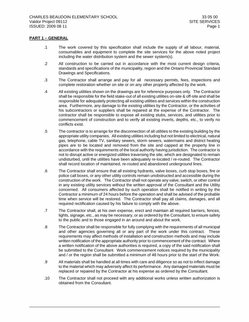
CHARLES BEAUDOIN ELEMENTARY SCHOOL 33 05 00 Valdor Project 09112 SITE SERVICES ISSUED: 2009 08 11 Page 1
PART 1 – GENERAL .1 The work covered by this specification shall include the supply of all labour, material,
consumables and equipment to complete the site services for the above noted project including the water distribution system and the sewer system(s).
.2 All construction to be carried out in accordance with the most current design criteria,
standards and specifications of the municipality, region and the Ontario Provincial Standard Drawings and Specifications.
.3 The Contractor shall arrange and pay for all necessary permits, fees, inspections and
complete restoration whether on site or on any other property affected by the work.
.4 All existing utilities shown on the drawings are for reference purposes only. The Contractor shall be responsible for the field stake-out of all existing utilities on-site & off-site and shall be responsible for adequately protecting all existing utilities and services within the construction area. Furthermore, any damage to the existing utilities by the Contractor, or the activities of his subcontractors or suppliers shall be repaired at the expense of the Contractor. The contractor shall be responsible to expose all existing stubs, services, and utilities prior to commencement of construction and to verify all existing inverts, depths, etc., to verify no conflicts exist.
.5 The contractor is to arrange for the disconnection of all utilities to the existing building by the
appropriate utility companies. All existing utilities including but not limited to electrical, natural gas, telephone, cable TV, sanitary sewers, storm sewers, watermains and district heating pipes are to be located and removed from the site and capped at the property line in accordance with the requirements of the local authority having jurisdiction. The contractor is not to disrupt active or energized utilities traversing the site, which are designated to remain undisturbed, until the utilities have been adequately re-located / re-routed. The Contractor shall record location of maintained, re-routed and abandoned underground lines.
.6 The Contractor shall ensure that all existing hydrants, valve boxes, curb stop boxes, fire or
police call boxes, or any other utility controls remain unobstructed and accessible during the construction of the work. The Contractor shall not operate any valve, switch, or other control in any existing utility services without the written approval of the Consultant and the Utility concerned. All consumers affected by such operation shall be notified in writing by the Contractor a minimum of 24 hours before the operation and shall be advised of the probable time when service will be restored. The Contractor shall pay all claims, damages, and all required rectification caused by his failure to comply with the above.
.7 The Contractor shall, at his own expense, erect and maintain all required barriers, fences,
lights, signage, etc., as may be necessary, or as ordered by the Consultant, to ensure safety to the public and to those engaged in an around and about the work.
.8 The Contractor shall be responsible for fully complying with the requirements of all municipal
and other agencies governing all or any part of the work under this contract. These requirements may affect methods of installation and construction methods and may include written notification of the appropriate authority prior to commencement of the contract. Where a written notification of the above authorities is required, a copy of the said notification shall be submitted to the Consultant. Work commencement notices required by the municipality and / or the region shall be submitted a minimum of 48 hours prior to the start of the Work.
.9 All materials shall be handled at all times with care and diligence so as not to inflect damage
to the material which may adversely affect its performance. Any damaged materials must be replaced or repaired by the Contractor at his expense as ordered by the Consultant.
.10 The Contractor shall not proceed with any additional works unless written authorization is
obtained from the Consultant.
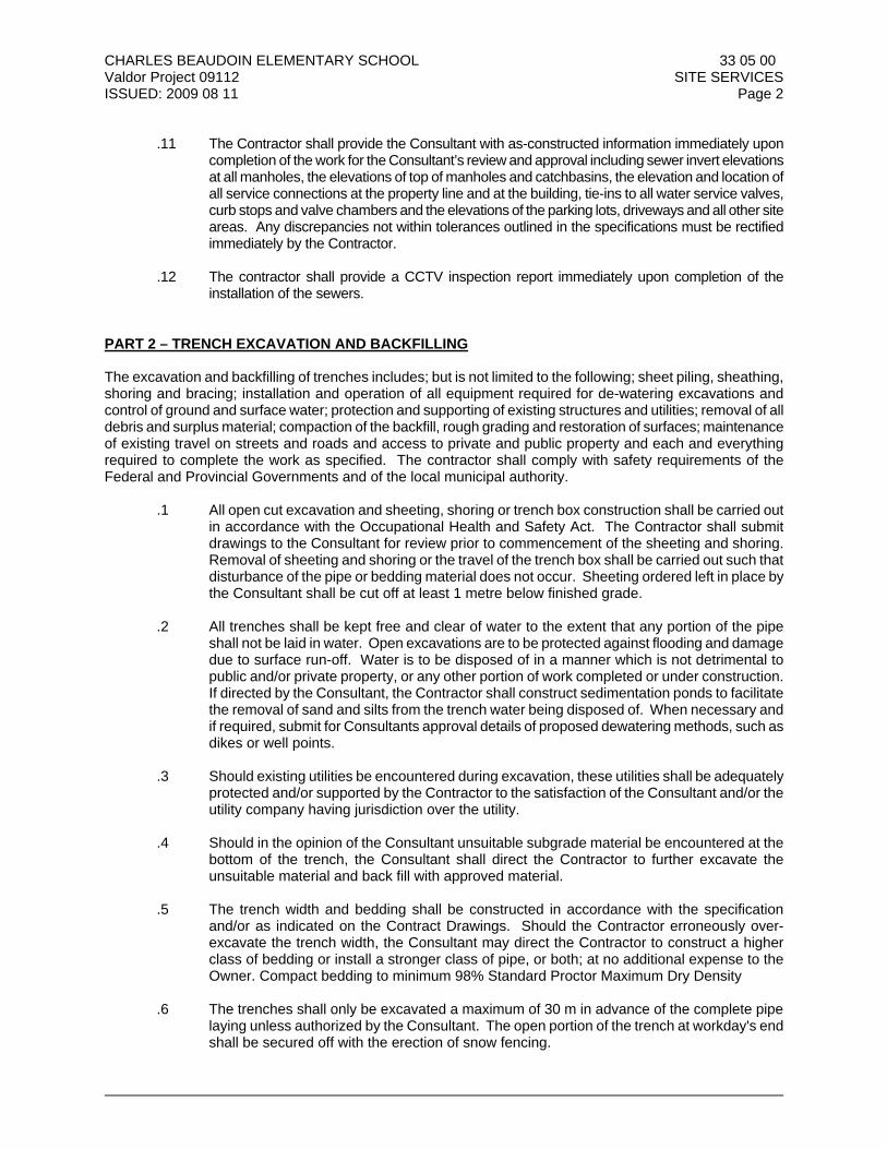
CHARLES BEAUDOIN ELEMENTARY SCHOOL 33 05 00 Valdor Project 09112 SITE SERVICES ISSUED: 2009 08 11 Page 2
.11 The Contractor shall provide the Consultant with as-constructed information immediately upon
completion of the work for the Consultant’s review and approval including sewer invert elevations at all manholes, the elevations of top of manholes and catchbasins, the elevation and location of all service connections at the property line and at the building, tie-ins to all water service valves, curb stops and valve chambers and the elevations of the parking lots, driveways and all other site areas. Any discrepancies not within tolerances outlined in the specifications must be rectified immediately by the Contractor.
.12 The contractor shall provide a CCTV inspection report immediately upon completion of the
installation of the sewers. PART 2 – TRENCH EXCAVATION AND BACKFILLING The excavation and backfilling of trenches includes; but is not limited to the following; sheet piling, sheathing, shoring and bracing; installation and operation of all equipment required for de-watering excavations and control of ground and surface water; protection and supporting of existing structures and utilities; removal of all debris and surplus material; compaction of the backfill, rough grading and restoration of surfaces; maintenance of existing travel on streets and roads and access to private and public property and each and everything required to complete the work as specified. The contractor shall comply with safety requirements of the Federal and Provincial Governments and of the local municipal authority.
.1 All open cut excavation and sheeting, shoring or trench box construction shall be carried out in accordance with the Occupational Health and Safety Act. The Contractor shall submit drawings to the Consultant for review prior to commencement of the sheeting and shoring. Removal of sheeting and shoring or the travel of the trench box shall be carried out such that disturbance of the pipe or bedding material does not occur. Sheeting ordered left in place by the Consultant shall be cut off at least 1 metre below finished grade.
.2 All trenches shall be kept free and clear of water to the extent that any portion of the pipe
shall not be laid in water. Open excavations are to be protected against flooding and damage due to surface run-off. Water is to be disposed of in a manner which is not detrimental to public and/or private property, or any other portion of work completed or under construction. If directed by the Consultant, the Contractor shall construct sedimentation ponds to facilitate the removal of sand and silts from the trench water being disposed of. When necessary and if required, submit for Consultants approval details of proposed dewatering methods, such as dikes or well points.
.3 Should existing utilities be encountered during excavation, these utilities shall be adequately
protected and/or supported by the Contractor to the satisfaction of the Consultant and/or the utility company having jurisdiction over the utility.
.4 Should in the opinion of the Consultant unsuitable subgrade material be encountered at the
bottom of the trench, the Consultant shall direct the Contractor to further excavate the unsuitable material and back fill with approved material.
.5 The trench width and bedding shall be constructed in accordance with the specification
and/or as indicated on the Contract Drawings. Should the Contractor erroneously over-excavate the trench width, the Consultant may direct the Contractor to construct a higher class of bedding or install a stronger class of pipe, or both; at no additional expense to the Owner. Compact bedding to minimum 98% Standard Proctor Maximum Dry Density
.6 The trenches shall only be excavated a maximum of 30 m in advance of the complete pipe
laying unless authorized by the Consultant. The open portion of the trench at workday's end shall be secured off with the erection of snow fencing.
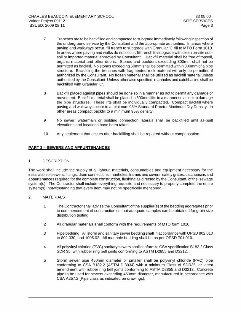
CHARLES BEAUDOIN ELEMENTARY SCHOOL 33 05 00 Valdor Project 09112 SITE SERVICES ISSUED: 2009 08 11 Page 3
.7 Trenches are to be backfilled and compacted to subgrade immediately following inspection of the underground service by the Consultant and the appropriate authorities. In areas where paving and walkways occur, fill trench to subgrade with Granular 'C' fill to MTO Form 1010. In areas where paving and walks do not occur, fill trench to subgrade with clean on-site sub-soil or imported material approved by Consultant. Backfill material shall be free of topsoil, organic material and other debris. Stones and boulders exceeding 300mm shall not be permitted as backfill. No stones exceeding 50mm shall be permitted within 300mm of a pipe structure. Backfilling the trenches with fragmented rock material will only be permitted if authorized by the Consultant. No frozen material shall be utilized as backfill material unless authorized by the Consultant. Unless otherwise specified, manholes and catchbasins shall be backfilled with Granular 'C'.
.8 Backfill placed against pipes should be done so in a manner as not to permit any damage or
movement. Backfill material shall be placed in 300mm lifts in a manner so as not to damage the pipe structures. These lifts shall be individually compacted. Compact backfill where paving and walkways occur to a minimum 98% Standard Proctor Maximum Dry Density. In other areas compact backfill to a minimum 95% density.
.9 No sewer, watermain or building connection laterals shall be backfilled until as-built
elevations and locations have been taken.
.10 Any settlement that occurs after backfilling shall be repaired without compensation. PART 3 – SEWERS AND APPURTENANCES 1. DESCRIPTION The work shall include the supply of all labour, materials, consumables and equipment necessary for the installation of sewers, fittings, drain connections, manholes, frames and covers, safety grates, catchbasins and appurtenances required for the complete construction, flushing as directed by the Consultant, of the sewage system(s). The Contractor shall include everything requisite and necessary to properly complete the entire system(s), notwithstanding that every item may not be specifically mentioned. 2. MATERIALS
.1 The Contractor shall advise the Consultant of the supplier(s) of the bedding aggregates prior to commencement of construction so that adequate samples can be obtained for grain size distribution testing.
.2 All granular materials shall conform with the requirements of MTO form 1010.
.3 Pipe bedding: All storm and sanitary sewer bedding shall in accordance with OPSD 802.010
to 802.030, and 1005.02. All manhole bedding shall be as per OPSD 701.010. .4 All polyvinyl chloride (PVC) sanitary sewers shall conform to CSA specification B182.2 Class
SDR 35, with rubber ring bell joints conforming to ASTM D2855 and D3212.
.5 Storm sewer pipe 450mm diameter or smaller shall be polyvinyl chloride (PVC) pipe conforming to CSA B182.2 (ASTM D.3034) with a minimum Class of SDR35, or latest amendment with rubber ring bell joints conforming to ASTM D2855 and D3212. Concrete pipe to be used for sewers exceeding 450mm diameter, manufactured in accordance with CSA A257.2 (Pipe class as indicated on drawings).
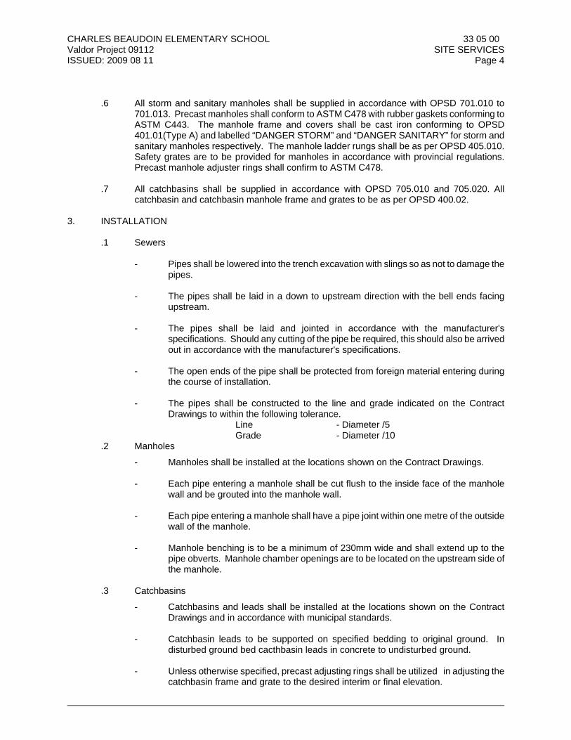
CHARLES BEAUDOIN ELEMENTARY SCHOOL 33 05 00 Valdor Project 09112 SITE SERVICES ISSUED: 2009 08 11 Page 4
.6 All storm and sanitary manholes shall be supplied in accordance with OPSD 701.010 to
701.013. Precast manholes shall conform to ASTM C478 with rubber gaskets conforming to ASTM C443. The manhole frame and covers shall be cast iron conforming to OPSD 401.01(Type A) and labelled “DANGER STORM” and “DANGER SANITARY” for storm and sanitary manholes respectively. The manhole ladder rungs shall be as per OPSD 405.010. Safety grates are to be provided for manholes in accordance with provincial regulations. Precast manhole adjuster rings shall confirm to ASTM C478.
.7 All catchbasins shall be supplied in accordance with OPSD 705.010 and 705.020. All
catchbasin and catchbasin manhole frame and grates to be as per OPSD 400.02.
3. INSTALLATION
.1 Sewers - Pipes shall be lowered into the trench excavation with slings so as not to damage the
pipes. - The pipes shall be laid in a down to upstream direction with the bell ends facing
upstream. - The pipes shall be laid and jointed in accordance with the manufacturer's
specifications. Should any cutting of the pipe be required, this should also be arrived out in accordance with the manufacturer's specifications.
- The open ends of the pipe shall be protected from foreign material entering during
the course of installation. - The pipes shall be constructed to the line and grade indicated on the Contract
Drawings to within the following tolerance. Line - Diameter /5 Grade - Diameter /10
. 2 Manholes
- Manholes shall be installed at the locations shown on the Contract Drawings. - Each pipe entering a manhole shall be cut flush to the inside face of the manhole
wall and be grouted into the manhole wall.
- Each pipe entering a manhole shall have a pipe joint within one metre of the outside wall of the manhole.
- Manhole benching is to be a minimum of 230mm wide and shall extend up to the
pipe obverts. Manhole chamber openings are to be located on the upstream side of the manhole.
. 3 Catchbasins
- Catchbasins and leads shall be installed at the locations shown on the Contract Drawings and in accordance with municipal standards.
- Catchbasin leads to be supported on specified bedding to original ground. In
disturbed ground bed cacthbasin leads in concrete to undisturbed ground. - Unless otherwise specified, precast adjusting rings shall be utilized in adjusting the
catchbasin frame and grate to the desired interim or final elevation.
CHARLES BEAUDOIN ELEMENTARY SCHOOL 33 05 00 Valdor Project 09112 SITE SERVICES ISSUED: 2009 08 11 Page 5
4. TESTING
.1 Storm and sanitary sewer testing:
Infiltration Test
- Isolate the upstream end of the section to be tested with a plug or bulkhead. - Place a V notch weir or other approved measuring device in the pipe at the lower
end.
- The duration of the test shall be two hours. The actual infiltration shall be the average of at least 8 readings taken at even intervals during the test.
Exfiltration Test - Isolate the section to be tested by temporarily blocking the inlets of two manholes
with expandable plug or bulkheads. - Fill the pipe and manhole with water to a depth of 600mm above the crown of the
pipe in the upstream manhole. Do not exceed 7.5m maximum head at the downstream manhole.
- Allow 24 hours for absorption of water and escape of air from the line.
- The duration of a test shall be two hours. The actual exfiltration shall be determined
by measuring the change of elevation of the water in the manhole.
Air Test - The test section shall be plugged at each end. - All service laterals, stubs and fittings into the sewer test section shall be property
capped or plugged.
- Air shall be supplied to the test section slowly, until a constant pressure of 25 kPa is maintained. If the ground water is above the sewer line being tested, the air pressure shall be increased by 3.0 kPa for each foot the ground water level is above the invert of the pipe.
- A stabilization period of at least 5 minutes shall be allowed during which time the
pressure shall be regulated to prevent it from fluctuating more than 10 kPa above or more than 3.5 kPa below the required pressure.
.2 Allowable Limits Storm Sewer of Tests
- Infiltration - 0.28 litres per hour per millimetre of pipe diameter per 100 metres of
sewer (0.28 1/hr/mm dia/100mm). - Exfiltration - 0.35 litres per hour per millimetre of pipe diameter per 100 metres of
sewer (0.35 1/hr/mm dia/100mm).
CHARLES BEAUDOIN ELEMENTARY SCHOOL 33 05 00 Valdor Project 09112 SITE SERVICES ISSUED: 2009 08 11 Page 6
.3 Allowable Limits of Sanitary Sewer Tests:
- Infiltration - 0.09 litres per hour per millimetre of pipe diameter per 100 metres of sewer (0.09 1/hr/mm dia/100mm).
- Exfiltration - 0.11 litres per hour per millimetre of pipe diameter per 100 metres of
sewer (0.11 1/hr/mm dia/100mm). - Air Tests - The test pressure shall be 3.5 kPa less than the above required pressure.
The time required for a pressure loss of 3.5 kPa shall not be less than that shown in the following table.
Time Required for Air testing
Pipe Size (mm) Time
Min Sec
100 2 32 150 3 50
200 5 06 250 6 22
300 7 39 PART 4 – WATER DISTRIBUTION SYSTEM 1. DESCRIPTION The work shall include the supply of all labour, materials, consumables and equipment necessary for the installation of watermains, fittings, valves, valve boxes, valve chambers, service connections, blowoffs, hydrants and appurtenances necessary for the complete construction, flushing, disinfection and testing of the water distribution system as detailed on the Contract Drawings and as specified. The Contractor shall include everything requisite and necessary to properly complete the entire system, notwithstanding that every item may not be specifically mentioned. 2. MATERIALS .1 All watermains and appurtenances shall conform to the municipal specification.
.2 All polyvinyl chloride (PVC) watermains shall be Class 150, SDR18, AWWA C900-97 and diameter 100mm to 300mm. Wall thickness to conform to cast iron (CI) outside diameter (OD). Pipes to have integral wall-thickened bells ends. Joining to be accomplished by using rubber rings conforming to ASTM F-477.
.3 Tracer wire shall be 12 gauge stranded copper CSA Type T.W.H.
.4 Hydrants:
- Hydrant make and model shall be from the approved list in accordance with municipal standards. Break away flange set 0.05 – 0.15 m above finished grade.
- Nozzles and threads and colours as specified by the municipality.
CHARLES BEAUDOIN ELEMENTARY SCHOOL 33 05 00 Valdor Project 09112 SITE SERVICES ISSUED: 2009 08 11 Page 7
.5 Valves:
- Gate valves to be iron body, bronze mounted, double-disc type, double faced and sealed, non-rising stem, conforming to AWWA C509-01, and the latest municipal standards.
- Valve ends to be mechanical joint - AWWA C111 (ANSI A21.11). - Minimum safe working pressure 1035 kPa.
- Direction of opening and type of operating nut to conform with municipal standards.
- Valve make and model to be from the approved list in accordance with municipal
standards.
.6 Valve Boxes:
- Round, cast iron, 2 piece adjustable slide or auger type with lift out cover. - Upper section - minimum diameter 110 mm. - Adjustment - minimum + 150 mm - overlap at full extensions shall be at least 150
mm. - Lower section - completely enclose valve with guide plate attached to valve.
- Valve boxes to be supplied in accordance with municipal standards.
.7 Fittings:
- Ductile iron fittings to conform to AWWA C110 (ANSI A21.10) with 1724 kPa pressure rating.
- Joints to conform to AWWA .
- Where fittings are used with ductile iron pipe electrical conductivity must be provided.
.8 Plug and blow-offs to be supplied in accordance with OPSD 1104.030.
3. INSTALLATION .1 Watermains shall be laid to the line and grade indicated on the Contract Drawings and shall
meet the depth of cover specified. Deviation from this line and grade shall not be more than 75 mm.
.2 Pipe Installation - Pipe lengths shall be laid and jointed in accordance with the manufacturer's
instruction and without damage to the pipes. Pipe joints may be deflected to provide for a long radius curve provided this is carried out to within the manufacturer's specifications.
.3 Mechanical joint nuts shall be tightened in alternating 180 degree positions with a torque
wrench to the manufacturer's specifications.
CHARLES BEAUDOIN ELEMENTARY SCHOOL 33 05 00 Valdor Project 09112 SITE SERVICES ISSUED: 2009 08 11 Page 8
.4 Valve installation - Valves shall be installed at the locations shown on the Contract Drawings
with the stems vertical and plumb and in accordance with municipal standards. All valves to open in a counter-clockwise direction.
.5 Valve box Installation - Valve boxes shall be installed at the locations shown on the Contract
Drawings and shall be centred and plumbed overtop the valve operating nut with the top set to finished grade level.
.6 Hydrant Installation - Hydrants shall be installed at the locations shown on the Contract
Drawings and in accordance with OPSD 1105.010. Hydrants shall be connected to the main with a 150mm ductile iron branch tee or as indicated on the drawing(s), controlled by an independent gate valve. The hydrant "boot" shall be installed against undisturbed soil with concrete anchorage. The hydrant valve box shall be centred and plumb over the gate valve and set to its finished grade level. The hydrant shall be installed with the barrel plumb and the hose connections parallel to the curb. The hydrant flange elevation shall be set to between 50 and 150mm above its finished grade level. The hydrant "boot" shall be backfilled with 25mm clear crushed limestone.
.7 Thrust Anchorage - All bends, fittings, tees, hydrants subject to movement due to pressure
thrust shall be anchored with concrete thrust blocking between them and undisturbed soil to prevent such movement. Concrete thrust blocking shall be constructed in accordance with OPSD 1103.010 and 1103.020.
.8 Connections to Existing Water Mains - Obtain permission from the operating authority before
making any connections to an existing water main. Valves on existing water mains shall not be operated by the Contractor unless approved by the Consultant and the operating authority. All affected water users shall be notified in writing at least 24 hours in advance of any planned interruption of service. Swab fittings and pipes placed into the existing line with a solution of chlorine having a minimum strength of 50 ppm. Take precautions to prevent contamination of the existing system and follow all instructions of the operating authority.
.9 Plug and Blow-offs - Temporary plug and blow-offs shall be constructed in accordance with
OPSD 1104.030 for the purposes of hydrostatic testing, and chlorination and flushing. .10 Tracer Wire - Tracer wire shall be taped to the watermains with fibreglass tape every 3 m
(Min). .11 Cathodic Protection - Zinc anodes shall be affixed to all ferrous watermain fittings and tracer
wire in accordance with current municipal standards. 3 . HYDROSTATIC TESTING
.1 After the pipe has been laid and backfilled, all newly laid pipe or valve sections shall be subject to a hydrostatic pressure test. The pressure test shall be of 1035 kPa and shall last at least two hours in duration.
.2 Each valve section of pipe shall be slowly filled with water and the specified test pressure,
based on the elevation of the lowest point of the line or section under test and corrected to the elevation of the test gauge, shall be applied by means of a pump connected to the pipe in a manner satisfactory to the Consultant. The pump, pipe connection and all necessary apparatus including gauges shall be furnished by the Contractor. The Contractor will furnish the gauge for the test and will make all taps into the pipe and the Contractor shall furnish all labour and material for conducting tests. All testing conform to municipal procedures and shall be performed in the presence of the Consultant and if required, the municipal operating authority.
CHARLES BEAUDOIN ELEMENTARY SCHOOL 33 05 00 Valdor Project 09112 SITE SERVICES ISSUED: 2009 08 11 Page 9
.3 Before applying the specified test pressure, all air shall be expelled from the pipe. If hydrants
or blow-offs are not available at high points, the Contractor shall make the necessary taps at his expense at points of highest elevation before the test is made and insert the plugs after the test has been completed.
.4 All exposed pipes, fittings, valves, hydrants and joints will be carefully examined. Any
cracked or defective pipe fittings, valves or hydrants discovered in consequence of this pressure test shall be removed and replaced by the Contractor with sound material and the test shall be repeated until satisfactory to the Consultant.
.5 A leakage test shall be conducted after the pressure test has been satisfactorily completed.
The Contractor will furnish the pump, pipe, connections and all labour and material to conduct the test.
.6 No pipe installation will be accepted until the leakage is less than 222 litres per 100 mm
diameter per kilometre per 24 hours based on a 1035 kPa pressure. .7 Should any test of water main laid disclose leakage greater than that specified, the Contractor
shall, at his own expense, locate and repair the defective joints until the leakage is within the specified allowance.
.8 All testing of the water mains and fitting such as hydrostatic pressure test, chlorination,
flushing required, requested or performed by the municipality or Consultant will be the responsibility of the Contractor. All costs associated with the testing will be borne by the Contractor.
4. CHLORINATION .1 When the Contractor has completed the installation of the water main and has carried out
satisfactorily the specified pressure and leakage test thereon, he shall thoroughly flush the whole system so as to remove completely from the system all unwanted matter.
.2 When required flushing has been completed satisfactorily, the Contractor shall proceed with
disinfection of the system in accordance with the procedures established by the municipality. .3 Upon completion of the disinfection procedure, water samples are to be taken and tested in
accordance with the municipal procedures. The watermain system shall not be put into operation until test results have been obtained and clearances have been given by the authority having jurisdiction.
___________________________________________________________________ End of Section No. 33 05 00