Embed Size (px)
Citation preview
SECTION 10
CHARGING SYSTEM
CONTENTS
10-l. ALTERNATOR . . . . . . . . . . ..L............. . . . . . . . . . . . .:. . . GENERAL DESCRIPTION 10-2
DATA AND SPECIFICATION . . . . . . . . . . . . . . . . . . . . . . . . . . . . . . . 10-3
DIAGNOSIS . . . . . . . . . . . . . . . . . . . . . . . . . . . . . . . . . . . . . . . . . . . . 10-3
REMOVAL . . . . . . . . . . . . . . . . . . . . . . . . . . . . . . . . . . . . . . . . . . . . 10-6DISASSEMBLY . . . . . . . . . . . . . . . . . . . . . . . . . . . . . . . . . . . . . . . . . 10-6INSPECTION . . . . . . . . . . . . . . . . . . . . . . . . . . . . . . . . . . . . . . . . . . . 10-8ASSEMBLY . . . . . . . . . . . . . . . . . . . . . . . . . . . . . . . . . . . . . . . . . . . . 10-9
10-2. BATTERY . . . . . . . . . . . . . . . . . . . . . . . . . . . . . . . . . . . . . . . . . . . . . 10-10GENERAL DESCRIPTION . . . . . . . . . . . . . . . . . . . . . . . . . . .. . . . . 10-10
CARE OF THE BATTERY . . . . . . . . . . . . . . . . . . . . . . . . . . . . . . . . 10-10
REMOVE AND REPLACE . . . . . . . . . . . . . . . . . . . . . . . . . . . . . . . . 10-12BATTERY CABLE . . . . . . . . . . . . . . . . . . . . . . . . . . . . . . . . . . . . . . 10-12
. . . . . . . . . . . . . . . . . . . . . . . . . . . . . . 10-2
10
10-1
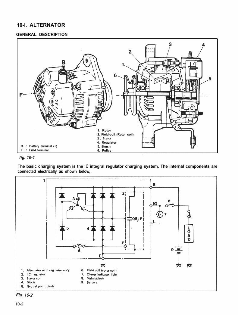
10-l. ALTERNATORGENERAL DESCRIPTION
B :F :
Battery terminal (+)
-1. Rotor2. Field-coil (Rotor coil)3 . Stator4. Regulator5. Brush
Field terminal 6. Pulley
The basic charging system is the IC integral regulator charging system. The internal components areconnected electrically as shown below,
Th Th*1. Alternator with regulator ass’y 6. Field coil (rotor coil)2. IX. regulator 7. Charge indicator light3. Stator coil 8. Mein switch4. Diode 9. Battery5. Neutral point diode
fig. 10-1
10-2
The alternator features a solid state regulatorthat is mounted inside the alternator. All regula-tor components are enclosed into a solid mold,and this unit along with the brush holder assemb-ly is attached to the slip ring end frame. Theregulator voltage setting cannot be adjusted.
The alternator rotor bearings contain enoughgrease to eliminate the need for periodic lubri-cation. Two brushes carry current through thetwo slip rings to the field coil mounted on therotor, and under normal conditions will providelong period of attention-free service.
The stator windings are assembled on the insideof a laminated core that forms part of thealternator frame. A rectifier bridge connectedto the stator windings contains six diodes,and electrically changes the stator A.C. voltagesto a D.C. voltage which appears at the generatoroutput terminal.The neutral diodes serve to convert the voltagefluctuation at the neutral point to direct currentfor increasing the alternator output.
A condenser mounted in the end frame protectsthe diodes from high voltages and suppressesradio noise.
DATA AND SPECIFICATION
Nominal operatingvoltagaMax. alternator output
12 volts
45A
No-load alternator speed
I Direction of rotation Clockwise as view-ed from oullev side
Maximum permissiblealternator speedWorking temperaturerange
Rectification
15,000 rpm (r/min)
-3o- 90°C(-22 - 194” F)Full waverectification
Noisy AlternatorNoise from the alternator may be caused by aloose drive pulley, loose mounting bolts, wornor dirty bearings, defective diode, or defectivestator.
DIAGNOSISA charging circuit wiring diagram for alternatorconnection is shown above. To avoid damage,always follow these precautions:
1) Do not mistake the polarities of IG terminaland L terminal.
2) Do not create short circuit between IG andL terminals. Always connect these terminalsthrough a lamp.
3) Do not connect any load between L and E.
Trouble in the charging system will show upas one or more of the following conditions:a. Faulty indicator lamp operation.b. An undercharged battery as evidenced by
slow cranking or indicator clear with reddot.
c. An overcharged battery as evidenced byexcessive spewing of electrolyte from thevents.
10-3
A. Faulty Indicator Lamp Operation
Problem
Charge light does not lightwith ignition ON and engineoff
Charge light does not go outwith engine running(battery requires frequent re-charging)
Possible cause Correcti on
Fuse blown Check fuse
Light burned out Replace light
Wiring connection loose Tighten loose connections
IC regulator faulty Replace IC regulator
Drive belt loose or worn Adjust or replace drive belt
Battery cables loose, corroded or worn Repair or replace cables
IC regulator or alternator faulty Check charging system
Wiring faulty . Repair wiring
B. Undercharged Battery a. VoltmeterThis condition, as shown by slow cranking orindicator clear with red dot, can be caused byone or more of the following conditions eventhough the indicator lamp may be operatingnormally. The following procedures also applyto cars with a voltmeter.
1) Insure that the undercharged condition hasnot been caused by accessories left on forextended period.
2) Check drive belt for proper tension.3) If a battery defect is suspected, refer to
latter part of this section, p. 10-l 0 - p, 1 O-11.
4) Inspect wiring for defects. Check all connec-tions for tightness and cleanliness, includingslip connectors at alternator and bulkhead,and battery cable connections at battery,starter and ignition ground cable.
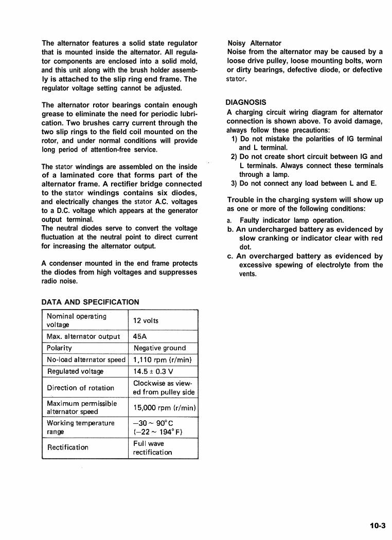
5) Connect voltmeter and ammeter as shown inthe diagram below.
Set between alternator (B) terminal andground.
b. AmmeterSet between alternator (B) terminal andbattery (+) terminal.
6) Current and voltage measurementsa. No-load check
Run engine from idling up to 2,000 r/min(rpm) and read meters.
NOTE:Consideration should be taken that the voltagewill vary somewhat with regulator case tempe-rature.
Fig. 10-3
10-4
1. Generator2. Ammeter3. Volt meter4. Battery6. Load6. Switch
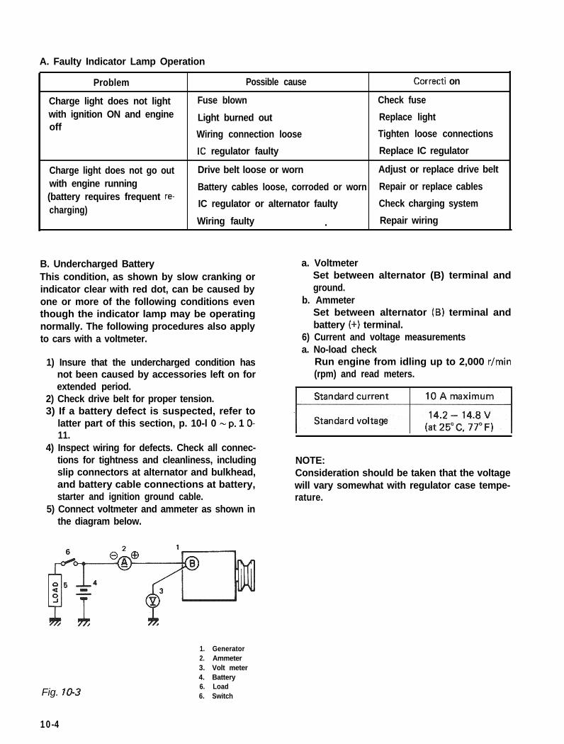
Volt
15.5 . .
14.5 _,
13.5 .,
15.3215.02
Run engine at 2,000 r/min (rpm) and turnon headlamps and heater motor.Measure current and if less than 20A, repairalternator.
C. Overcharged Battery1) If an obvious overcharge condition exists
as evidenced by excessive spewing of elec-trolyte, proceed to DISASSEMBLY under
I I II ALTERNATOR SERVICE on p. 10-6 and
-40°C 0 25Oc 135Oc check field windings for grounds and shorts.!-4O“FI (77’F) (275*F) If defective, replace rotor.
b. Load check
Fig. 10-4
If voltage is higher than standard value, replaceIC regulator.If voltage is below standard value, check ICregulator and alternator as follows:Ground F terminal and start engine. Thenmeasure voltage at B terminal.
Fig. 105 Grounding terminal ‘F”
If voltage is above standard value, replace ICregulator.If voltage is below standard value, check alter-nator.
10-5
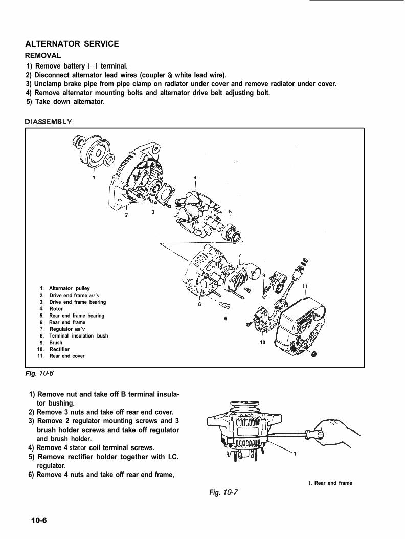
ALTERNATOR SERVICEREMOVAL1) Remove battery (-) terminal.2) Disconnect alternator lead wires (coupler & white lead wire).3) Unclamp brake pipe from pipe clamp on radiator under cover and remove radiator under cover.4) Remove alternator mounting bolts and alternator drive belt adjusting bolt.5) Take down alternator.
DIASSEMBLY
1. Alternator pulley2. Drive end frame ass’y3. Drive end frame bearing4. Rotor5. Rear end frame bearing6. Rear end frame7. Regulator aa’y6. Terminal insulation bush9. Brush
10. Rectifier11. Rear end cover
‘p” “i6
r10
Fig. 706
1) Remove nut and take off B terminal insula-tor bushing.
2) Remove 3 nuts and take off rear end cover.3) Remove 2 regulator mounting screws and 3
brush holder screws and take off regulatorand brush holder.
4) Remove 4 stator coil terminal screws.5) Remove rectifier holder together with I.C.
regulator.6) Remove 4 nuts and take off rear end frame,
Fig. 10-71. Rear end frame
10-6
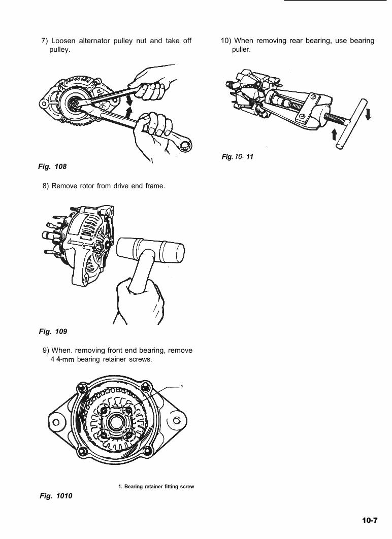
7) Loosen alternator pulley nut and take offpulley.
10) When removing rear bearing, use bearingpuller.
Fig. 108\ Fig. lo- 11
8) Remove rotor from drive end frame.
Fig. 109
9) When. removing front end bearing, remove4 4-mm bearing retainer screws.
Fig. 10101. Bearing retainer fitting screw
10-7
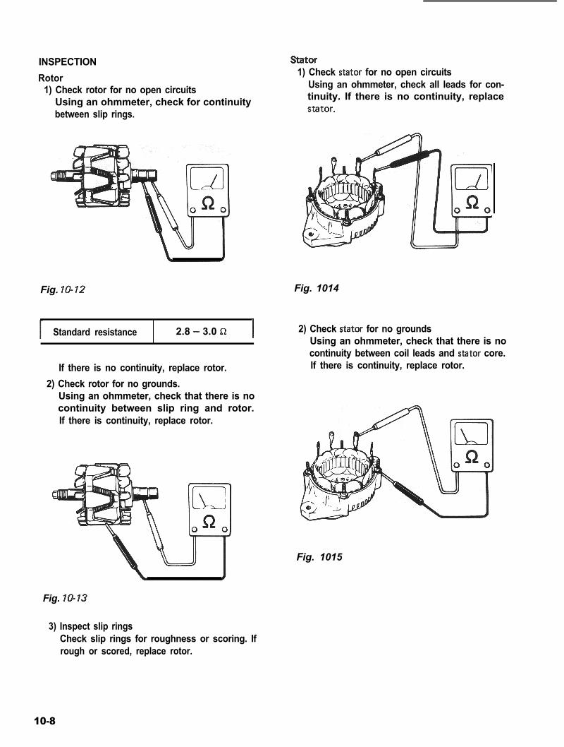
INSPECTION Stator
Rotor1) Check rotor for no open circuits
Using an ohmmeter, check for continuitybetween slip rings.
Fig. lo-12
Standard resistance 2.8 - 3.0 !a I
If there is no continuity, replace rotor.2) Check rotor for no grounds.
Using an ohmmeter, check that there is nocontinuity between slip ring and rotor.If there is continuity, replace rotor.
Fig. 10-13
1) Check stator for no open circuitsUsing an ohmmeter, check all leads for con-tinuity. If there is no continuity, replacestator.
Fig. 1014
2) Check stator for no groundsUsing an ohmmeter, check that there is nocontinuity between coil leads and stator core.If there is continuity, replace rotor.
Fig. 1015
3) Inspect slip ringsCheck slip rings for roughness or scoring. Ifrough or scored, replace rotor.
10-8
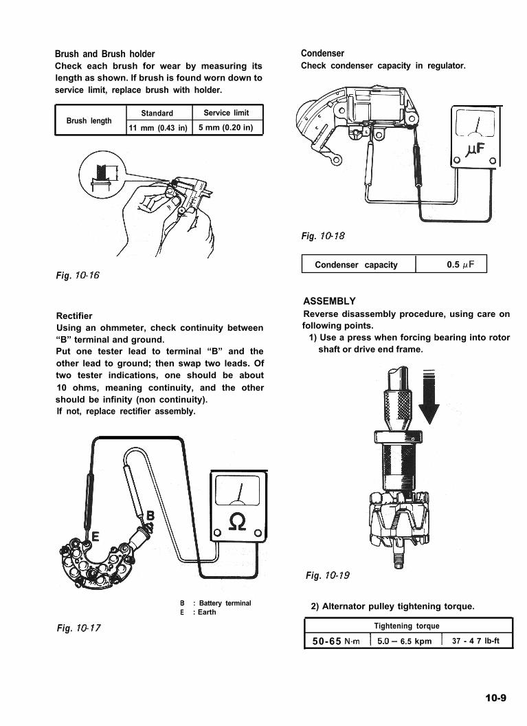
Brush and Brush holderCheck each brush for wear by measuring itslength as shown. If brush is found worn down toservice limit, replace brush with holder.
Brush lengthStandard Service limit
11 mm (0.43 in) 5 mm (0.20 in)
Fig. lo-16
RectifierUsing an ohmmeter, check continuity between“B” terminal and ground.Put one tester lead to terminal “B” and theother lead to ground; then swap two leads. Oftwo tester indications, one should be about10 ohms, meaning continuity, and the othershould be infinity (non continuity).If not, replace rectifier assembly.
CondenserCheck condenser capacity in regulator.
Fig. 10-18
I Condenser capacity 0.5 /JF
ASSEMBLYReverse disassembly procedure, using care onfollowing points.
1) Use a press when forcing bearing into rotorshaft or drive end frame.
Fig. lo-19
e : Battery terminalE : Earth
Fig. 10-17
2) Alternator pulley tightening torque.
Tightening torque
50-65 N-m 1 5.0- 6.5 kpm 1 37 - 4 7 lb-ft
10-9
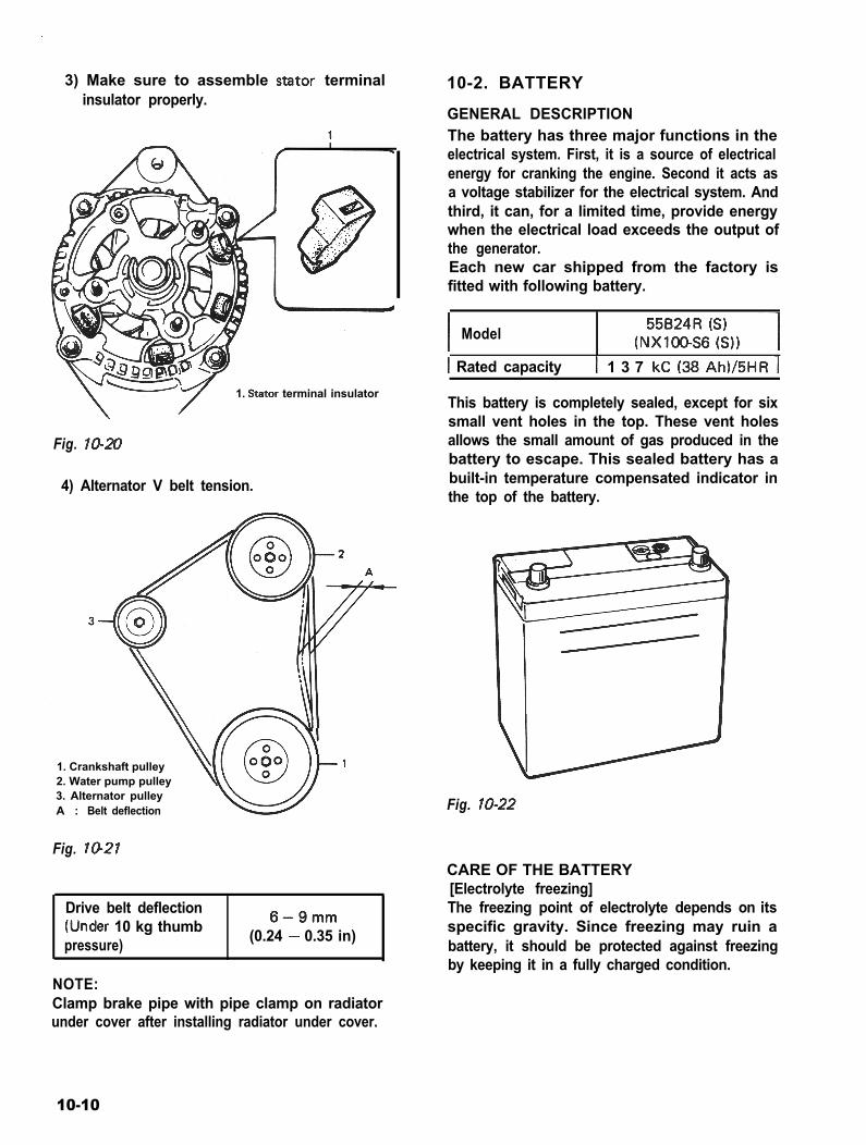
3) Make sure to assemble stator terminalinsulator properly.
10-2. BATTERY
1. Stator terminal insulator
Fig. lo-20
4) Alternator V belt tension.
1. Crankshaft pulley2. Water pump pulley3. Alternator pulleyA : Belt deflection
Fig. 1021
Drive belt deflection(Under 10 kg thumbpressure)
6-9mm(0.24 - 0.35 in)
NOTE:Clamp brake pipe with pipe clamp on radiatorunder cover after installing radiator under cover.
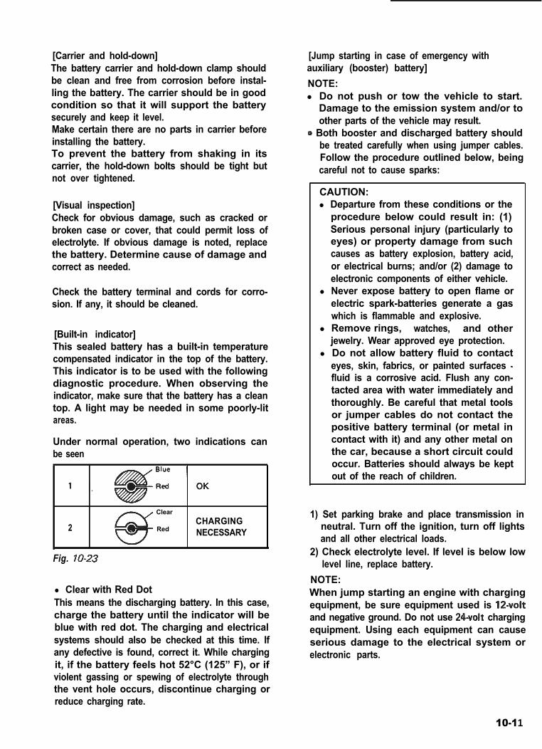
GENERAL DESCRIPTIONThe battery has three major functions in theelectrical system. First, it is a source of electricalenergy for cranking the engine. Second it acts asa voltage stabilizer for the electrical system. Andthird, it can, for a limited time, provide energywhen the electrical load exceeds the output ofthe generator.Each new car shipped from the factory isfitted with following battery.
I Model55BzR=l(NXIOO-S6 6))
1 Rated capacity t 1 3 7 kC (38 Ah)/5HR j
This battery is completely sealed, except for sixsmall vent holes in the top. These vent holesallows the small amount of gas produced in thebattery to escape. This sealed battery has abuilt-in temperature compensated indicator inthe top of the battery.
Fig. lo-22
CARE OF THE BATTERY[Electrolyte freezing]The freezing point of electrolyte depends on itsspecific gravity. Since freezing may ruin abattery, it should be protected against freezingby keeping it in a fully charged condition.
10-10
[Carrier and hold-down]The battery carrier and hold-down clamp shouldbe clean and free from corrosion before instal-ling the battery. The carrier should be in goodcondition so that it will support the batterysecurely and keep it level.Make certain there are no parts in carrier beforeinstalling the battery.To prevent the battery from shaking in itscarrier, the hold-down bolts should be tight butnot over tightened.
[Visual inspection]Check for obvious damage, such as cracked orbroken case or cover, that could permit loss ofelectrolyte. If obvious damage is noted, replacethe battery. Determine cause of damage andcorrect as needed.
Check the battery terminal and cords for corro-sion. If any, it should be cleaned.
[Built-in indicator]This sealed battery has a built-in temperaturecompensated indicator in the top of the battery.This indicator is to be used with the followingdiagnostic procedure. When observing theindicator, make sure that the battery has a cleantop. A light may be needed in some poorly-litareas.
Under normal operation, two indications canbe seen
2
Clear
RedCHARGINGNECESSARY
Fig. lo-23
l Clear with Red DotThis means the discharging battery. In this case,charge the battery until the indicator will beblue with red dot. The charging and electricalsystems should also be checked at this time. Ifany defective is found, correct it. While chargingit, if the battery feels hot 52°C (125” F), or ifviolent gassing or spewing of electrolyte throughthe vent hole occurs, discontinue charging orreduce charging rate.
[Jump starting in case of emergency withauxiliary (booster) battery]NOTE:l Do not push or tow the vehicle to start.
Damage to the emission system and/or toother parts of the vehicle may result.
8 Both booster and discharged battery shouldbe treated carefully when using jumper cables.Follow the procedure outlined below, beingcareful not to cause sparks:
CAUTION:l Departure from these conditions or the
procedure below could result in: (1)Serious personal injury (particularly toeyes) or property damage from suchcauses as battery explosion, battery acid,or electrical burns; and/or (2) damage toelectronic components of either vehicle.
l Never expose battery to open flame orelectric spark-batteries generate a gaswhich is flammable and explosive.
l Remove rings, watches, and otherjewelry. Wear approved eye protection.
l Do not allow battery fluid to contacteyes, skin, fabrics, or painted surfaces -fluid is a corrosive acid. Flush any con-tacted area with water immediately andthoroughly. Be careful that metal toolsor jumper cables do not contact thepositive battery terminal (or metal incontact with it) and any other metal onthe car, because a short circuit couldoccur. Batteries should always be keptout of the reach of children.
1) Set parking brake and place transmission inneutral. Turn off the ignition, turn off lightsand all other electrical loads.
2) Check electrolyte level. If level is below lowlevel line, replace battery.
NOTE:When jump starting an engine with chargingequipment, be sure equipment used is 12voltand negative ground. Do not use 24volt chargingequipment. Using each equipment can causeserious damage to the electrical system orelectronic parts.
10-11

3) Attach the end of one jumper cable to thepositive terminal of the booster battery andthe other end of the same cable to the positiveterminal of the discharged battery. Do notpermit vehicles to touch each other as thiscould cause a ground connection and counte-ract the benefits of this procedure. (Use12-volt battery only to jump start the engine).
4) Attach one end of the remaining negativecable to the negative terminal of the boosterbattery, and the other end to a solid engineground (such as A/C compressor bracket orgenerator mounting bracket) at least 18 inchesfrom the battery of the vehicle being started(DO NOT CONNECT DIRECTLY TO THENEGATIVE TERMINAL OF THE DEADBATTERY).
5) Start the engine of the vehicle that is provid-ing the jump start and turn off electricalaccessories. Then start the engine in the carwith the discharged battery.
6) Reverse these directions exactly when remov-ing the jumper cables. The negative cablemust be disconnected from the engine thatwas jump started first.
REMOVE AND REPLACEWhen handling a battery, the following safetyprecautions should be followed:
1) Hydrogen gas is produced by the battery.A flame or spark near the battery may causethe gas to ignite.
2) Battery fluid is highly acidic. Avoid spillingon clothing or other fabric. Any spilledelectrolyte should be flushed with largequantity of water and cleaned immediately.To remove or replace a battery, alwaysdisconnect the negative cable first, then thepositive cable.
BATTERY CABLESConnect battery cables as shown in the figurebelow and make sure to properly tighten allterminals.
1. Battery ground2. Starter cable
4. Fusible link
cable
Fig. IO-245. Wiring harness No. 2
10-12


![CHARGING SYSTEM LOCATION INDEX [LF] · 2010-12-28 · 2007 ELECTRICAL Charging System - MX-5 Miata CHARGING SYSTEM LOCATION INDEX [LF] Fig. 1: Identifying Location Of Charging System](https://img.pdfslide.us/doc/110x75/5e6fabe276dc3c268a2cd05c/charging-system-location-index-lf-2010-12-28-2007-electrical-charging-system.jpg)