Embed Size (px)
Citation preview

CHARAGERIZATION OF THE DISCHARGE COEFFICIENT OF A SONIC
VENTURI NOZZLE
A. Cruz-Mava1, F. Sánchez-Sllva2. P. Qulnto-Dlez2 & M. Toledo-Velázquez2
1 Programa Integral de Investigación en Gas. Instituto Mexicano del Petróleo,
Eje Central Lázaro Cárdenas 152, Col. San Bartolo Atepehuacan, 07730 Mexico DF.,Mexico. Unidad Profesional Interdisciplinaria de Ingeniería y Tecnologias Avanzadas,Departamento de Mecatrónica, IPN.2Laboratorio de Ingeniería Térmica e Hidráulica Aplicada, Sección de Estudios de Posgrado e Investigación,Escuela Superior de Mecánica e Ingeniería Electrónica, Instituto Politécnico Nacional.Av. IPN sIn Col. Lindavista, Edif. 5, UPALM, 07738, Mexico, DF., Mexico.
Received: November 17"', 2003. Accepted: May 24 'h, 2005
ABSTRAG
This paper identifles and determines the main parameters used to calculate the dlscharge coefficlent of a toroidal
Venturl nozzle accordlng to the ISO Standard 9300, operating at the critical flow regime (sonlc). Thls study was
conducted to investigate the effeds of the viscous stresses In the turbulent boundary layer, the wall thermal
boundary condition, and the flow fleld curvature at the nucleus of the nozzle on the dlscharge coefflclent by
means of a theoretical and numerlcal approach. Characterlzation of the dlscharge coefflclent in the Venturi sonlc
nozzle was performed consldering the viscous and multidlmenslonal effects of the flujd flow as uncoupledphenomenon. As a result. each non-ideal mechanism can be analyzed independently from the Inftuence of the
other mechanlsm. We present a numerlcal procedure to characterlze the dlscharge coefflclent In the invlscld
reglon of the ftow, by uslng the numerical simulation of the inviscld maln ftow by means of the commerclal CFD
code. In the region of the vlscous stresses, the charaderlzation of thls coefflclent is based on the analytlcal theory
of the turbulent boundary layer. Thls charaderization allowed obtalning a correlation of the dlscharge coefflclent
that was valldated by dlred comparlson between the experimental correlations of the dlscharge coefflclent In
turbulent boundary layer proposed by ISO-9300 and the Korea Research Institute of Standards and Sclence (KRISS).
Thls valldation was carried out for throat Reynolds numbers from 1.4 to 2.6x10'. The agreement of the theoretical
and measured dlscharge coefflclents by these correlations was better than 0.2%.
RESUMEN
En el presente artrculo se identifican y caracterizan los parámetros que Intervienen en la determinación del
coeficiente de descarga de toberas toroidales de flujo crítico bajo la norma 150-9300. El estudio se enfoca a
Investigar la Incidencia de los efectos viscosos en la región de capa límite y la curvatura del campo de flujo en el
núcleo de la tobera sobre el coeficiente de descarga. La caracterización del coeficiente de descarga se lleva acabo
dividiendo el flujo en dos zonas para su estudio, la primera zona considera los esfuerzos viscosos generados en la
región de capa límite, en la segunda zona, el flujo se considera no viscoso y el estudio se orienta hacia su
comportamiento no unidimenslonal. Cada uno de estos mecanismos es estudiado en forma Independiente sin la
influencia del otro, la caracterización del coeficiente en la región de flujo no viscoso se lleva a cabo mediante la
simulación numérica del flujo por medio de CFD. En la región de flujo viscoso, la caracterización del coeficiente se
lleva a cabo bajo un enfoque analítico, basado en la teoría de capa límite turbulenta. Como resultado de la
caracterización, se obtiene una correlación teórlco-numérica capaz de determinar el coeficiente de descarga
directamente sin necesidad de calibración. La correlación obteniqa fue validada mediante una comparación directa
contra correlaciones experimentales obtenidas en el Korea Research Institute of 5tandards and 5c1ence (KRI55) y la
104I/nl ? Nn 7 AJJÓJJ'óf 2nn.
norma 150-9300 para números de Reynolds en la garganta de la tobera de 1.4 a 2.6x1 O', la desviación es inferior al
0.2%.
KEYWORDS: Critical Nozzle, Discharge Coefflcient, Crltical Flow.
INTRODUGION
A Venturi sonic nozzle is a well-accepted and utilized f1ow measurement device in most high-pressure gas test
facilities. It is accurate and Its measurement uncertainty 15 well documented In the ISO 9300-1990 standard [1 ]. These
devices have numerous industrial appllcations, such as mass f1ow corTtrollers, and pressure isolators, besldes being
used as calibration standards for other gas f1ow meters. The development of the critical f1ow nozzle has now reached
the mature stage, where It can be used as a reference f1owmeter and to give traceability to the National Standard of
Flow Measurement. Representative crltical nozzle geometry, as recommended by the ISO 9300 Standard, was
selected for the base line of this study. Figure 1 shows the nozzle shape.
4d
;.1
2d/
3° 3°
~2.5d
1--V
Fi-"ure 7. Geomet¡y of the critical nozzle investi-"ated
The main advantage of the nozzle is its extremely simple constructlon, without any movlng parts, that may produce
friction or wear, leadlng to its long-term stabllity and excellent repeatability. Another important advantage is that the
critical flow prevents the propagatlon of pressure disturbances downstream of the throat nozzle. However, the
accuracy of the nozzle depends largely on whether or not the determination of its discharge coefficient is accurate;
the discharge coefficient plays an important role in gas flow measurement by means of critical Venturi nozzles. It is
known that the discharge coefficient of the Venturi nozzle 15 deflned as the ratio of the actual flowrate to one-
dimensional ideal flowrate. This coefficient should be characterized for viscous boundary layer and flow fleld curvature
(basically, two dimensional) effects. Therefore, it is always less than one, although quite close to the unit.
When a COmpre551ble fluid flOW5 through a converging then diverglng channel (5hown In figure 1 ), velocity reaChe5 a
maxlmal value at the polnt of minimal flow area (throat 5onic nozzle). The throat velocity Increase5 as the overall
differential pre55Ure acro55 channel Increa5e5. The limltlng value of throat velocity i5 the 5peed of 5ound; further
increase5 In overall differentlal pre55Ure wlll not re5ult in an increa5e in throat velocity. When the throat velocity
reaChe5 the 5peed of 5ound thi5 15 called crltlcal flow (M=l ) and the nozzle i5 5aid to be choked. The pre5enCe of
critlcal flow can be conflrmed by monitoring the critlcal pre55Ure ratlo. The critlcal flow Venturi 15 a converging then
diverging channel confjgured as a flow measurement devlce. When the flow 15 critlcal, the volumetric flowrate In the
throat i5 a fundlon of the 5peed of 5ound, the throat area, and the calibratlon Con5tant. The mas5 flowrate 15 a
fundlon of the volumetric flowrate and the fluid den5ity In the throat. Although Increaslng the 5tagnatlon Inlet
pre55Ure, p o, wlll not affed the volumetric flowrate, the mas5 flowrate wlll increase In proportlon to the fluld den5lty.
Wlth appropriate pre55Ure and temperature measurement5, a 5onlc nozzle can be u5ed to measure mas5 flowrate.
The mas5 flowrate will remaln Con5tant, If the 5tagnatlon pre55Ure and temperature and compo5itlon remaln
unchan~ed.
105
journalof Applled Ilesearch and Technology
The mass flowrate m of the Idear one-dimenslonal and isentropic fluid flowing through a sonlc nozzle Is given by
p A.C.o
m-
(1)mideal =
The analytlcal model 15 only valld for crltlcal flow (M=l ), the mass flowrate depends on measurement of the Inlet
pressure p o and the temperature T o, thelr values must be expressed In absolute unlts. The variables A" and R are the
throat area and the Ideal gas constant. The crltlcal flow fador C. represents the thermodynamlc chanQ;e In the
isentroplc flow from the staQ;natlon condltlon to the sonlc conditlon and It depends of the thermo-physlcal propertles
of the Q;as at the throat sonic nozzle, and the upstream temperature and pressure. The work of Johnson [2].
represented a breakthrouQ;h In accurate computatlon of C for real Q;ases. The Ideal mass flowrate model Q;lven by
equatlon (1) provldes a convenlent flrst order estimate of the adual mass flowrate throuQ;h a crltlcal sonlc nozzle (I.e",1-10% of readlnQ;, dependinQ; on Reynolds number). A better aQ;reement between theory and experiments can be
obtalned by includlnQ; Into the Ideal model, varlous non-ldeal mechanlsms that affed the adual mass flowrate. These
non-ldeal mechanlsms include the vlscous effeds in the boundary layer and the multl-dlmenslonal behavlor of the
flow"
To obtaln a better accuracy in the mass flowrate measurement provided for an ideal model, expressed In equation 1,
the dlscharge coeffident of the nozzle Cd must be included in thls equatlon. Thls parameter plays an Important role
on flow metrology using sonic nozzles; Cd attempts to account for deviatlons due to effeds of multldimensional flow
(viscOus effects on the boundary layer reglon and the effed of a curved sonlc surface). The discharge coeffident
compensates those effeds that strike the ideal behavior of the flow.
The dlscharQe coefflclent of the sonlc nozzle Is deflned as the ratio of the actual mass flowrate to the theoretical
flowrate correspondlnQ to Ideal one-dlmenslonal and Isentroplc flow, as shown below by equatlon 2
c =~d-
mjdeal
(2)
In this eQuation, the actual mass flowrate is deflned by the real mass flowrate that passes through the sonic nozzle;
eQuation (2) shows that Cd is a calibration factor of the nozzle. For a given nozzle geometry, the dlscharge coefficlent
changes as a function of the flowrate passing thought It.
Cd is usually expressed as a fundlon of the Reynolds number based on the throat diameter and the stagnation
viscoSity of the fluid lJoas follows
4macfual
1[ d.un
(3)Red =
The value of Cd 15 determlned from callbratln~ the 5onic nozzle by compari5on wlth a prlmary flow standard. The
uncertainty in Cd 15, therefore, the 5ame as the uncertainty in the calibration proce55. An equatlon for the callbratlon
proce55 can be written based on equation 1, as 5hown below
m actual ,fiiT:
~ A. C.
Cd = (4)
where maclual is the actual mass flowrate based on the primary flow standard
106
Vol] No.2 Augusl 2005
The uncertalnty ¡n Cdfrom equation (4) depend5 on the uncerta¡ntie5 In four compOnent5: mactua¡' Po. To, and C.and
i5 not a function of A., d. or R. beCaU5e the5e ValUe5 are kept Con5tant whenever the 5onlc nozzle 15 u5ed or
callbrated.
Nowaday5, thi5 coefficlent i5 determined experimentally throuQh the p(imary flow standard sy5tem; the experimental
calibratlon proce55 15 very expen5ive, becau5e of the biQ infra5tructure needed to carry it out. In order to eliminate the
calibration procedure, 5Ome re5earcher5 have developed analytical and numerlcal model5 to determine the di5CharQe
coefficlent under different operational condition5. Thi5 coefficlent 15 pre5ented as a fundion of fluid parameter5,
nozzle Qeometry, and the Reynold5 number based on the throat nozzle diameter. However, the5e model5 have
focu5ed on the laminar boundary layer flow [3- 6]. The characterization of the dl5CharQe coefficlent, carried out in thi5
work, allOW5 obtaininQ a new correlation of thi5 coefficlent, providinQ a reliable cajibration method at a low CO5t and
applicable to any e5tabli5hed Operational condition. It i5 important to note that the experimental di5CharQe
coeffjclent5 are obtained under certain condition5 e5tabli5hed durinQ the calibration proce55 that can be different of
the operational one5. Then, the di5charQe coeffjclent could chanQe.
2. THEORETlCAL BASIS
The characterization of the discharQe coefficient is dependent on the shape of the Venturi sonic nozzle and the
Reynolds number based on its throat diameter. It appears convenient to express one equation of the discharQe
coefficient in form of defed. i.e., the total defed in the discharQe coefficient consists of two parts: one is caused by
radially non-uniform (two dimensional) velocity distribution of the inviscid main flow and the other is due to the
viscous boundary layer effect. The corredions for nan-idealities due to multidimensianal effects and viscous effeds of
the Qas are considered as hiQher arder terms that are subtraded from the baseline (unity). AccardlnQ ta the
afarementianed. this cansideration can be written as
Cd = l-I1Cd-inv -L\C d-vis , (5)
where ¿jCd-inv is the Cd decrement due to the multidimensional effeds of the flow nucleus, ¿jCd-vis is the Cd redudion
due to the flow viscous effeds in the boundary layer. This expression considers the viscous and multidimensional
effeds of the fluid ~as as uncoupled phenomena. The combined effed of these non-ideal mechanisms is modeled as
a superposition of the individual effeds. As a result, each of the non-ideal mechanism can be analyzed Independently
from the influence of the other mechanism.
Mathematicallv, the dlschar~e coefflclent can be expressed as
c d = 1- (1- C d-jnv ) -(1- C d-vjs ) (6)
Thls equatlon does not represent a real ~as behavior, due to the compensation of critical flow factor C., since th¡s
behavior is compensated .¡n the critical flow factor. The analytical characterization of the dischar~e coefficient cons.¡sts
simply in determinin~ the non-ideal effects at the throat sonic nozzle.
The discharQe coefflclent can be calculated for an uncoupled form when the arder of maQnitude of the
multldimensional effects Is small and the boundary layer thlckness at the throat of the nozzle Is also small as
compared to the nozzle radlus. For a nozzle CuNature radius of at least twice the throat diameter these effects are
mlnlmal r71-
Accordin~ with equatlon (6), the flow can be divlded In two reQions for the dlscharQe coefficient study.
107
lournalof ADD/Ied Research and Technolollv
Vlscous Stress Reglon: In thls zone, the dlscharge coefficlent depends on boundary layer growth and viscous stress.
The dlscharge coefflclent in the vlscous reglan can be determined starting from the displacement thickness analyslsof the boundary layer ;. Under this approach, calculus of the discharge coefflclent in this zone depends on the
following fadors: Speclfic heat ratio y, Prandtl number Pr' standard radial temperature distribution at the throat nozzle
T ./T., compressible fador form Hc, momentum thickness of the boundary layer (}, displacement thickness of the
boundary layer ; , Reynolds number of the throat sonic nozzle, gas constant R, and nozzle ~eometry, as shown In the
followin~ correlation:
Cd-vis =f(r,~,Tw /To'Red'Hc'Hi,(),8.,R,geometry)
Invlscld Flow ReQlon: In this reQloni the flow Is Irrotatlonal, therefore the dlscharge coefflclent Is a fundlon of the
dlstortlon of the proflle velocltles In the nucleus of the flow, and the dlscharge coefflclent only depends on the
speclflc Qeometry of the nozzle and the speclflc heat ratlo 'Y of the flow, as shown In the followlnQ expresslon:
Cd-inv = f(y,geometry)
These fadors are used to determine the discharQe coefficlent for Qases that behave nearly ideally over the ranQe of
thermodynamic condltions typical of critical nozzle flows. However. the above expression can also be used where real
Qas effeds are Important by usinQ the critical factor flow C. determined by Johnson [2].
Another phenomenon strikes on the dlscharge coefficient durlng flow acceleratlon from the stagnation polnt to sonic
condltlons. The phenomenon 15 characterized by a reversible thermal energy transformatlon, so temperaturedecreases while gas is accelerated through the convergent sectlon of the nozzle. In small-scale nozzles, flow
acceleratlon takes place In very small distances; consequently the flow residence time In the nozzle is not sufficient to
reach equillbrium between the vibratory energy of fluld molecules and the thermodynamlc environmental condltlons.
Thls phenomenon 15 known as vibratory relaxatlon, it affeds considerably polyatomic gases (y=1.JJ) [7].
3. DISCHARGE COEFFlCIENT DEFINITION
Dischar~e coefficient in turbulent boundary layer3
The presence of vlscous effects In the nozzle tends to decrease the mass flowrate below its Ideal value glven In
equation ( 1 ). Physlcally, the no-sllp condltion exlsting at the nozzle wall results In a layer of slow moving fluid adjacentto the rigid wall (I. e., the boundary layer). Furthermore, wlthln the boundary layer the fluld's kinetic energy is
irreversibly converted Into Internal energy (I. e., vlscous dlssipation) so that the boundary layer temperature Is higher
than the free stream temperature. The hlgher temperature throughout the boundary layer results in a decrement of
fluld density near the rigld wall. Together, the lower than ideal values of fluid velocity and denslty In the boundary
layer yleld a redudlon In mass flowrate from that predlcted by the one-dlmenslonallnvlscid flow solution. The vlscous
effeds can be accounted for by deflnlng an effedlve throat area In such a manner that the mass flow predlcted by
one-dlmensionallnvlscid flow theory is equlvalent to the actual value of mass flow through the nozzle.
The calculus of the dlschar~e coefflclent In the boundary layer zone begins with the following premlse:
íhe mass nowrate that would pass through a nozzle in absence of viscous stresses is bigger than the one it would
pass when bounda¡y layer exists'
Conslderln~ the previOuS statement, the mass flowrate decreases due to the viscous stresses and It can be evaluated
by subtractin~ the area where vlscous stresses exist from the total throat area. Such a procedure takes away) the
boundarv laver disDlacement thlckness (¿t). This parameter is deflned asthe dlstance that the ri~ld wall would have to
108
Vol J No.2 August 2005
move In a flow in order to generate the mass flowrate redudlon due to the boundary layer. In fad, It takes Into
account an effedlve area. The displacement thlckness (8") can be expressed as follows
8. = K 1- ~ )dy (7)
In equation (7), the term (u/U) represents the diminution of the velocity flow in the throat sonic nozzle due to the
presence of the boundary layer, where u is the flow velocity in the boundary layer and U is the flow velocity outside
the boundary layer. Mathematically, the effective throat radius equals the actual throat radius minus the displacement
thickness ( t). One-dimensional isentropic flow theory can be used to determine the viscous mass flowrate once the
nozzle's riQid wall is displaced inward by (t). Given that the density and flowat the sonic throat are independent
from the throat size, the viscous discharQe coefficient can be deflned as the ratio of the effective nozzle throat area to
the adual nozzle throat. In this way, the discharQe coefficient in the reQion of viscous flow can be related with the
boundary layer displacement thickness (t) [8], as expressed in equation (8)
c -48.d-vis -1-~
d
(8)
In the equation (8), the discharge coefficlent is a fundion of the viscous stresses only, under a one-dlmensional focus,
d iS the throat sonic nozzle diameter. The viscous discharge coefflclent equation (8) It can be replaced in the equation
(6). in order to obtaln the viscous and inviscld dlscharge coefficlent, as follows
4{5*
d
Cd = Cd-inv (9)
In the prevlous equation, Cd-jnv is undefined. The displacement thlckness has been determined previously by means
of the turbulent boundary layer theory under a two-dimensional focus, for gases with Pr =0.7, y= 1.4, and critical
conditions, these characteristics are typical of most of the gases quantified using sonic nozzles. The displacementthickness determination is given in more detail in reference [8]. Substitution of the displacement thickness in
equation (9) charaderlzes the viscous discharge coefficient, as follows
-0.09970 Re -:.2113564Cd = Cd-inv (10)
3.2 Discharge coefficient In Invlscid flow
In thl5 5edion, the di5charge coefficlent in the nUcleU5 of the 5onic nozzle 15 determined. In thi5 zone, the flow i5 free
from Vi5COU5 5tre55e5; therefore, the di5charge coefficlent depend5 only on the curvature of the flow in the nozzle and
the type of fluid. The ideal flow model approXimate5 the nozzle flow as a one-dlmen5ional flow fleld; adually, the
nozzle flow i5 multi-dimen5ional. The5e multi-dimen5ional effed5 re5ult in a curvature of the 5onic line in the radial
plane of the throat 5onic nozzle, thi5 curvature redUCes the adual mas5 flow relatlve to mideal. In multl-dimen5ional
flOW5 (negleding VI5COU5 effed5), the 5onic line folloW5 an approximately parabolic profjle that begln5 jU5t up5tream
of the throat along the nozzle wall and extend5 dOwn5tream into the diverglng 5edion of the nozzle to it5 vertex on
the centerline. Con5equently, the flow at the throat cro55-5edion will have, in general, a 5Uper50nic veloclty near the
wall (i. e., M> 1 ), and a 5ub50nic veloclty near the centerllne (i. e., M<l ). On the other hand, the 5onic line 15 flat for
one-dimenslonallnvisc1d flow 50 that a unlform 5onlc veloclty (I. e., M=l) exl5t5 everywhere along the throat crO55-
5edlon. Thi5 effed can be Ob5erved by mean5 of the numerical 5lmulation of the flow in the 5onic nozzle by mean5 of
the CFD, as 5hown In fjgure 2.
109
lournalof Aoolled Research and TechnoloJlY
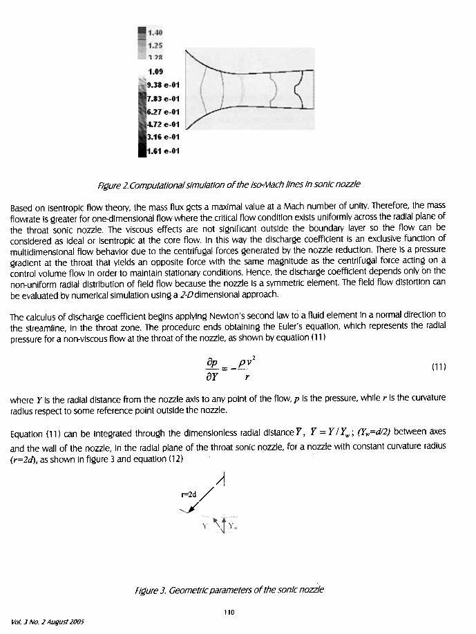
Figure 2. Computatlonal slmulatlon ofthe Iso-Mach Ilnes In sonlc nozzle
Based on 15entroplc flow theory, the mas5 flux ~et5 a maxlmal value at a Mach number of unlty. Therefore, the mas5
fiowrate 15 ~reater for one-dlmenslonal fiow where the critical fiow condltion exl5t5 unlformly acro55 the radial plane of
the throat 5onlc nozzle. The VI5COU5 effect5 are not 51~nlflcant out5ide the boundary layer 50 the fiow can be
con5idered as Ideal or 15entroplc at the core flow. In thi5 way the dl5Char~e coefflclent i5 an eXclU5lve functlon of
multidlmen5ional fiow behavlor due to the centrlfu~al fOrCe5 ~enerated by the nozzle reduction. There 15 a pre55Ure~radient at the throat that yield5 an OPPo51te force wlth the same ma~nitude as the centrlfu~al force actln~ on a
control volume flow in order to malntaln 5tationary condition5. Hence, the dl5Char~e coefflclent depend5 only on the
non-unlform radial dl5tribution of fjeld flow beCaU5e the nozzle 15 a 5ymmetrlc element. The fjeld flow di5tortion can
be evaluated by numerlcal 5imulation u5ln~ a 2-Ddlmen5lonal approach.
The calculus of discharge coefficient begins applying Newton's second law to a fluid element in a normal direction to
the streamline, in the throat zone. The procedure ends obtaining the Euler's equation, which represents the radial
pressure for a non-viscous flow at thethroatofthe nozzle, as shown by equation (11 )
2
~=-~ay r
(11)
where y Is the radial distance from the nozzle axls to any point of the flow, p is the pressure, while r Is the curvature
radius respect to some reference point outside the nozzle.
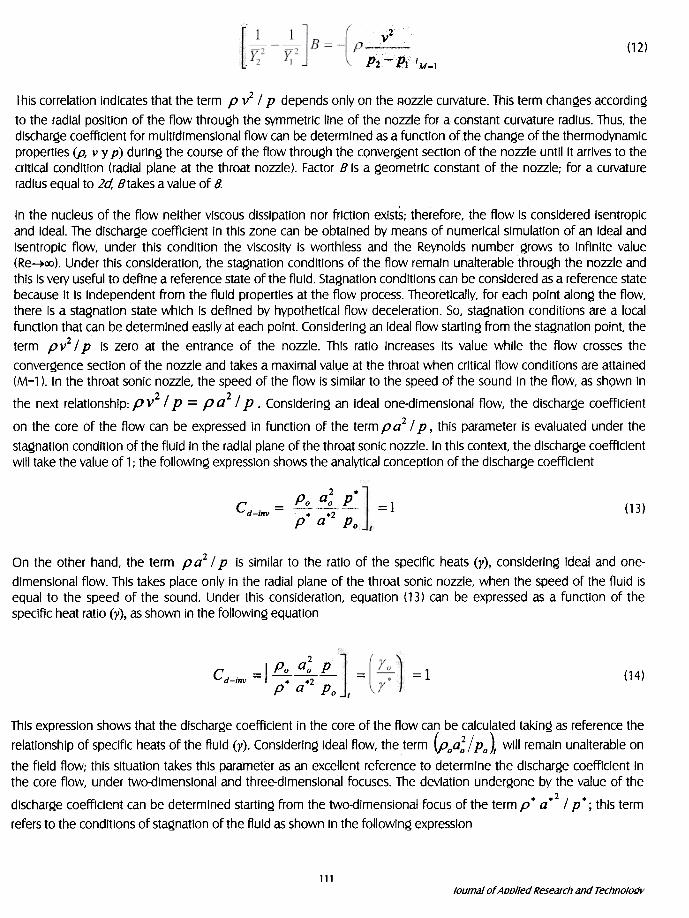
Equatlon (11) can be Integrated through the dlmenslonless radial dlstanCeY, y=y/yw; (Yw=dl2) between axes
and the wall of the nozzle, In the radial plane of the throat sonic nozzle, for a n.ozzle with constant curvature radlus
(r=2d), as shown In figure 3 and equation (12)
)¡r=2d /
J
Figure ]. Geometrlc parameters of the sonlc nozzle
110
Vol] No.2 August 2005
(12)
2.v,
P2 PI 'M=l
This correlatlon Indicates that the term p v2 / p depends onlyon the /;)ozzle curvature. Thls term changes according
to the radial positlon of the flow through the symmetric Ilne of the nozzle for a constant curvature radlus. Thus. the
dlscharge coefficlent for multldlmensional flow can be determlned as a functlon of.the change ofthe thermodynamlc
properties (p, v y p) durlng the course of the flow through the convergent sectlon of the nozzle untillt arrives to the
crltlcal condltlon (radial plane at the throat nozzle). Factor B Is a geometrlc constant of the nozzle; for a curvature
radius equal to 2a: Btakes a value of 8.
In the nucleus of the flow neither viscouS dissipation nor friction exists; therefore, the flow is consldered isentropic
and ideal. The dlscharge coefflclent In thls zone can be obtained by means of numerical simulation of an Ideal and
Isentropfc flow, under thfs condftion the viscosfty fs worthless and the Reynolds number grows to infjnite value
(Re~00). Under thfs consfderation, the stagnation conditions of the flow remain unalterable through the nozzle and
thls is very useful to defjne a reference state of the fluid. Stagnation conditions can be consldered as a reference state
because it 15 independent from the fluld properties at the flow process. Theoretica/1y, for each pofnt along the flow,
there is a stagnation state whlch fs defjned by hypothetical flow deceleration. So, stagnation condftions are a local
function that can be determlned easfly at each point. Considering an ideal flow starting from the stagnation point, the
term pv2 / p fs zero at the entrance of the nozzle. This ratio Increases its value whfle the flow crosses the
convergence sedion of the nozzle and takes a maxfmal value at the throat when critical flow conditions are attained
(M=l ). In the throat sonic nozzle, the speed of the flow is similar to the speed of the sound fn the flow, as sh9wn in
the next relationship: p v2 / p = p a2 / p .Consldering an ideal one-dimensfonal flow, the dfscharge coefflclent
on the core of the flow can be expressed in function of the term p a2 / p , thls parameter is evaluated under the
stagnation condftion of the flufd fn the radial plane of the throat sonic nozzle. In thfs context, the discharge coefflclent
wf/1 take the value of 1; the fo/1owfng expressiOn shows the analytlcal conception of the discharge coefflclent
2 .
Po °o p---
p. 0.2 Po
c d-inv = =1 (13)
On the other hand, the term p a2 / p is similar to the ratio of the spedfic heats (y), considerinQ ideal and one-
dimensional flow. This takes place only in the .radial plane of the throat sonic nozzle, when the speed of the fluid is
equal to the speed of the sound. Under this consideratlon, equation (13) can be expressed as a functlon of the
spedflc heat ratio ()I), as shown in the followin~ equation
2
Po ao pCd-inv = I =1 (14)=---..2
p a Po
Thls expressiOn shows that the discharge coefflclent In the core of the flow can be calculated taklng as reference the
relationship of speclflc heats of the fluld (y). Considering ideal flow, the term (poa: / Po)t wlll remaln unalterable on
the fleld flow; thls situation takes this parameter as an excellent reference to determine the discharge coefflclent in
the core flow, under two-dimensional and three-dlmensional focuses.The devlatlon undergone by the value of the2
discharge coefficlent can be determlned starting from the two-dimenslonal focus of the term p. a. / p. ; this term
refers to the conditlons of stagnation of the fluid as shown In the following expression
111
lournalof Aoolled Research and Technoloúv
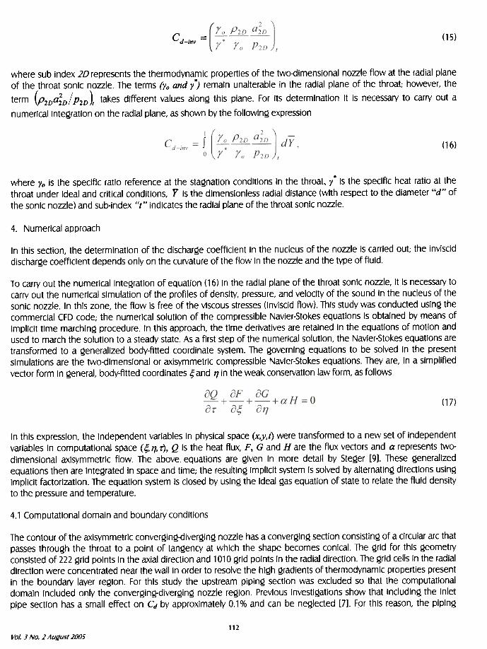
Cd-inv = (15)
where sub index 2D represents the thermodynamic properties of the two-dimensional nozzle flow at the radial plane
of the throat sonlc nozzle. The terms (Yo and y.) remaln unalterable In the radial plane of the throat; however. the
term (P2Da;D / P2D )1 takes dlfferent values along thls plane. For its determlnation It Is necessary to carry out a
numerlcallntegratlon on the radial plane, as shown by the followlng expression
(16)
where Yo 15 the 5pecific ratio reference at the 5tagnatlon condltion5 In the throat, y. i5 the 5pecific heat ratio at the
throat under Ideal and crltical condltion5. y i5 the dlmen51onle55 radial di5tance (wlth re5ped to the diameter "d» of
the 5onic nozzle) and 5ub-index "t» indlcate5 the radial plane ofthe throat 5onic nozzle.
4. Numerlcal approach
In thls sedlon, the determlnation of the discharge coefflcient in the nucleus of the nozzle is carrled out; the inviscid
dlscharge coefflcient depends only on the curvature of the flow in the nozzle and the type of fluld.
T o carry out the numerlcal inte~ratlon of equatlon ( 16) in the radial plane of the throat sonic nozzle, it Is necessary to
carry out the numerlcal slmulatlon of the proflles of denslty, pressure, and veloclty of the sound In the nucleus of the
sonlc nozzle. In this zone, the flow Is free of the viscous stresses (InviScld flow). This study was conduded usin~ the
commerclal CFD code; the numerical solutlon of the compressible Navler-Stokes equatlons Is obtalned by means of
impllclt time marchln~ procedure. In thls approach, the time derlvatlves are retained in the equatlons of motlon and
used to march the solutlon to a steady state. As a flrst step of the numerlcal solutlon, the Navler-Stokes equatlons are
transformed to a ~eneralized body-fltted coordlnate system. The ~overnln~ equatlons to be solved in the present
slmulatlons are the two-dlmensional or axisymmetric compresslble Navler-Stokes equatlons. They are, In a slmplifled
vedor form In ~eneral, body-fltted coordlnates ,; and 17 in the weak conservatlon law form, as follows
(17)
In this expresslon, the Independent variables in physlcal space (x,y,t) were transformed to a new set of Independent
variables in computational space (r;,17, r), Q is the heat flux, F, G and H are the flux vectors and a represents two-
dimensional axisymmetrlc fiow. The above eQuatlons are ~iven in more detail by Ste~er [9]. These ~enerallzed
eQuations then are Inte~rated in space and time; the resultln~ impllclt system 15 solved by alternatin~ diredlons usln~
impllclt fadorlzation. The eQuation system 15 closed by usin~ the ideal ~as eQuation of state to relate the fiuid density
to the pressure and temperature.
4.1 Computational domain and boundary conditions
The contour of the axisymmetric conver~in~-diver~in~ nozzle has a conver~in~ sedion consistin~ of a circular arc that
passes throu~h the throat to a point of tan~ency at which the shape becomes conical. The ~rid for this ~eometry
consisted of 222 ~rid points in the axial diredion and 1010 ~rid points in the radial diredion. The ~rid cells in the radial
diredion were concentrated near the wall in order to resolve the hi~h ~radients of thermodynamic properties presentin the boundary layer re~ion. For this study the upstream pipin~ sedion was excluded so that the computational
domain Included only the conver~ing-diver~in~ nozzle re~ion. Previous investi~ations show that includin~ the inlet
pipe sedion has a small effed on Cd by approximately 0.1% and can be ne~leded [7]. For this reason, the pipin~
112
Vol. J No.2 August 2005
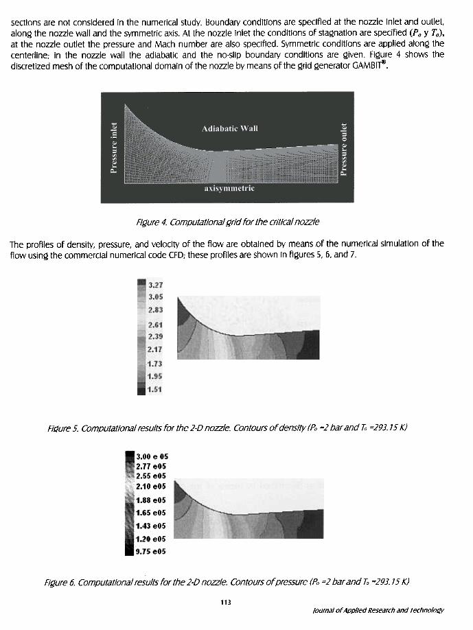
sectlons are not consldered in the numerical study. Boundary conditions are specifjed at the nozzle inlet and outlet.
along the nozzle wall and the symmetric axis. At the nozzle inlet the condltions of stagnation are specifjed (P o y T o),
at the nozzle outlet the pressure and Mach number are also specifjed. Symmetrlc conditions are applled along the
centerline; in the nozzle wall the adiabatic and the no-slip boundary conditions are given. Figure 4 shows the
discretized mesh ofthe computational domain ofthe nozzle by means 9fthe grid generator GAMBlfi!i.
Figure 4. Computational grid for thecrilical nozzle
The proflles of density. pressure, and veloclty of the flow are obtalned by means of the numerical simulation of the
flow using the commerclal numerical code CFD; these profiles are shown in figures 5, 6, and 7.
Flí1ure 5. Com.outatlonal resultsfor the 2-D nozzle. Contours of denslty (Po =2 bar and ¡;; =293.15 K)
Figure 6. Computational results for the 2-0 nozzle. Contours of pressure (Po =2 bar and ¡;, =293.15 K)
113
Journalof App!Jed Research and Technology
1 3.41 eO2
",3.35 eO2¡k¡¡ , "'"' ¡"
'3.28 eO2
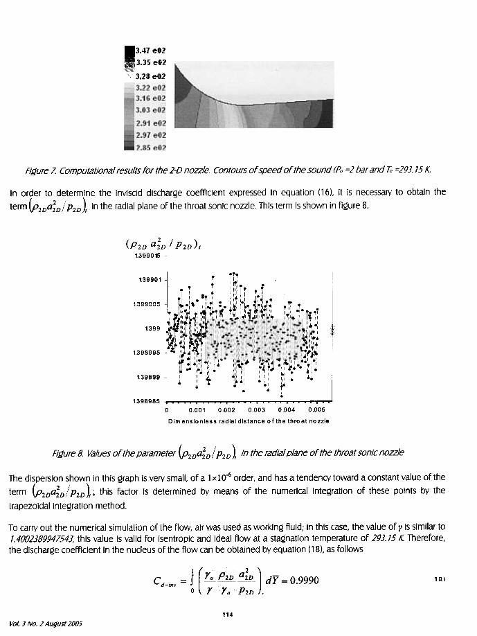
Figure 1. Computational results for the 2-0 nozzle. Contours of speed of the sound (Po =2 bar and ¡;; =293.15 K
In order to determine the inviscid discharge coefficient expressed in equation (16), it is necessary to obtain the
term (P2Da;D / P2D )t in the radial plane of the throat sonlc nozzle. This term is shown in figure 8.
(P2D a;D
1.399015
/ P2D )1
1.39901 ' I~ ,
, ~ , ,, I. I 'I I' , ~
~i' .T" 1¡111:\'~, ,.~~~~~~ :,r :1;,: ;,111 \1~ ~~":,.T. ,;r , .
"~II' "lt,I"II'~'III' 1\" I~ ,\\ i~~II ~" '~"II~ ,I ~~:,~!~!'11';1~~ 1~\.'IIT
1 ii,\",~I'II "' ~1\j:.~,,~.1'.'~_'I f!I'\~'~ ' .1
1.399 ; 1:':I:I',\:,~ :','I~I'I':i"'" \1",;~!1;~~:, II' '
~I~M\I¡IW~'~I ':~\ ,1,:¡¡~~,*.
1 I" .! I I :r4 " 11 I I ; I " , I' ~ 11 , ,~ I 1,~
~ ',1~ I , "11 ~ ' I'. I ,-..11 ~ "1111 I I ~.~.,:.;
1.398995 1" '~ I~'I ~ '.1' ~ III 'W~ ~11 '~ !IJ"~11 I,~/..
~ ',ti '11 ~I.. 1!~:'I,. " ¡r~~.~.'~~'..':..': .1
I 1.1.~III:I. ':1"~ tl~~.:~~l~.':~~ ~ I!, .',1 I! I, ~ , ~ ,
1.39899 ! , o1L .1111 1 1' I'. ..~ ' ./.1 I ...
.~ .T~
1.398985
0 0.001 0.002 0.003 0.004 0.005
D im ensio nless radial distance of the thro at nozzle
'.'oonn~
Figure 8. Values of the parameter {P2DaiD / P2D )1 In the radial plane of the throat sonlc nozzle
The disperslon shown in this graph Is very small, of a 1 x 10⁻⁶ order, and has a tendency toward a constant value of the
term (P2Da;D/ P2D )t ; thls factor Is determlned by means of the numerlcal Integratlon of these polnts by the
trapezoldallntegratlon method.
To carry out the numerlcal simulatlon of the flow, alr was used as worklng fluid; in this case, the value of y is similar to
1.4002389947543. this value Is valid for isentroplc and Ideal flow at a stagnation temperature of 293.15 K. Therefore,
the dlscharge coefflclent In the nucleus ofthe flow can be obtalned by equatlon (18). as follows
c .= J[~~~)dY=O.9990 d-mvyypO o 2D ,
1 Al
114
Vol] No.2 August 2005
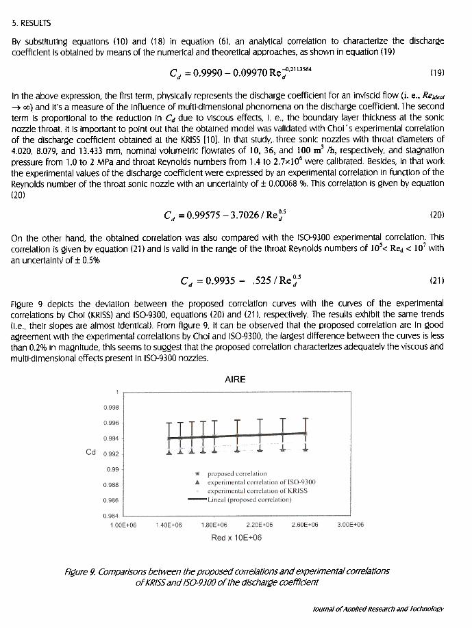
5. RESUlTS
By substltutlng equatlons (10) and (18) In equatlon (6), an analytlcal correlatlon to characterlze the dlscharge
coefflclent Is obtalned by means of the numerlcal and theoretlcal approaches, as shown In equatlon ( 19)
Cd =0.9990-0.09970Re-:.2113564 (19)
In the above expression, the flrst term, physically represents the discharQe coefficient for an inviscid flow (i. e., Rejdeal
-+ 00) and it's a measure of the influence of multi-dimensional phenomena on the discharQe coefficient. The second
term is proportional to the reductlon in Cd due to viscous effeds, i. e., the boundary layer thickness at the sonicnozzle throat. It is important to point out that the obtained model was validated with Choi ' s experimental correlation
of the discharQe coefficient obtained at the KRISS [10]. In that study, three sonic nozzles with throat diameters of
4.020, 8.079, and 13.433 mm, nominal volumetric flowrates of 10, 36, and 100 m3 /h, respectively, and staQnation
pressure from 1.0 to 2 MPa and throat Reynolds numbers from 1.4 to 2.7x10⁶ were calibrated. Besides, in that work
the experimental values of the discharQe coefficient were expressed by an experimental correlation in function of the
Reynolds number of the throat sonic nozzle with an uncertalnty of :t 0.00068 %. Thls correlation is Qiven by eQuation
(20)
Cd =0.99575 -3.7026/Re~5 (20)
On the other hand, the obtained correlation was also compared with the 150-9300 experimental correlation. This
correlation is Qiven by equation (21) and is valid in the ranQe of the throat Reynolds numbers of 105< Red < 107 with
an uncertaint\Í of:t 0.5%
.525 / Re ~.5Cd = 0.9935 - (21 )
Figure 9 deplcts the devlatlon between the proposed correlatlon curves with the curves of the experimental
correlations by Choi (KRI55) and 150-9300, equations (20) and (21 ), respectlvely. The results exhibit the same trends(I.e., thelr slopes are almost identlcal). From figure 9, it can be observed that the proposed correlation are In good
agreement wlth the experimental correlations by Choi and 150-9300, the largestdifference between the curves is less
than 0.2% in magnitude, this seems to suggest that the proposed correlatlon characterizes adequately the viscous and
multl-dimenslonal effects present in 150-9300 nozzles.
AIRE
Figure 9. CompariSOnS between the proposed correlations and experimental correlationsof KR/55 and /50-9300 of the d/scharge coeftlcient
lournalof Aoolled Research and Technololly
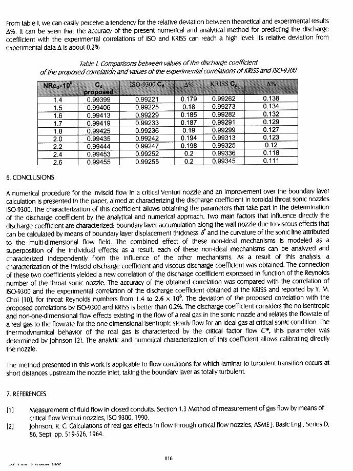
From table I, we can easlly percelve a tendency for the relative deviation between theoretlcal and experimental re5ult5
~%. It can be 5een that the accuracy of the pre5ent numerlcal and analytical method for predlding the dl5chargecoefflclent wlth the experimental correlatlon5 of 150 and KRI55 can reach a hlgh level: it5 relatlve devlatlon from
experimental data ~ 15 about 0.2%.
Tab/e /. Comparisons between va/ves of the discharge coefficientof the proposed corre/atioi1 and va/ves of the experimenta/ corre/ations of KR/55 and /50-9300
---0.992620.992730.99282
0.992910.992990.993130.993250.993360.99345
0.1380.1340.1320.1290.1270.1230.12
0.1180.111
---0.992210.992250.992290.992330.992360.992420.992470.992520.99255
0.1790.18
0.1850.1870.19
0.1940.198
0.20.2
0.99399
0.99406
0.994130.994190.994250.994350.994440.99453n~~455
1.41.51.61.71.82.02.22.42.6
6. CONClUSIONS
A numerical procedure for the Invlscld flow In a crltical Venturi nozzle and an improvement over the boundary layercalculatlon 15 presented In the paper, aimed at characterlzing the dlscharge coefflclent In toroldal throat sonlc nozzles
150-9300. The characterization of thls coefflclent allows obtainlng the parameters that take part in the determlnatlonof the dlscharge coefflclent by the analytical and numerlcal approach. Two maln factors that influence dlrectly the
discharge coefficlent are characterlzed: boundary layer accumulation along the wall nozzle due to viscous effects that
can be calculated by means of boundary layer displacement thickness t and the curvature of the sonic Ilne attributed
to the multi-dimensional flow field. The comblned effect of these non-ldeal mechanlsms is modeled as a
superposltion of the individual effects; as a result, each of these non-ideal mechanisms can be analyzed and
characterlzed Independently from the influence of the other mechanlsms. As a result of thls analysis, a
characterlzation of the inviscld dlscharge coefflclent and viscous discharge coefflclent was obtained. The connection
of these two coefflclents yielded a new correlation of the discharge coefflclent expressed in function of the Reynoldsnumber of the throat sonic nozzle. The accuracy of the obtained correlation was compared with the correlatlon of
150-9300 and the experimental correlatlon of the discharge coefflclent obtained at the KRI55 and reported by Y. M.
Choi [10], for throat Reynolds numbers from 1,4 to 2,6 x 10⁶, The deviation of the proposed correlation with the
proposed correlations by 150-9300 and KRI55 is better than 0.2%. The discharge coefflclent conslders the no isentropicand non-one-dimensional flow effects existing in the flow of a real gas In the sonic nozzle and relates the flowrate of
a real gas to the flowrate for the one-dimensional isentropic steady flow for an ideal gas at critical sonlc condltion. The
thermodynamical behavior of the real gas 15 characterized by the critical factor flow C*, this parameter was
determined by Johnson [2]. The analytic and numerical characterization of this coefflclent allows calibrating directly
the nozzle.
The method presented In this work Is applicable to flow conditions for which laminar to turbulent transltion occurs at
short distances upstream the nozzle Inlet, taking the boundary layer as totally turbulent.
7. REFERENCES
!1] Measurement of fluld flow In closed condults. Sectlon 1.3 Method of measurement of ~as flow by means of
critlcal flow Venturl nozzles, 150 9300. 1990.Johnson, R. c. Calculatlons of real ~as effects In flow throu~h crltlcal flow nozzles, ASME J. Baslc En~., Serles D.
86, Sept. pp. 519-526.1964.[2]
116
'_1 .,,- ..A..A..r' ..nnc
[3]
[6]
f7l
[8]
Stratford, B. S. 1he calcu.latlon ofthe discharge coefficient of profiled choked nozzles and optlmum proflle for
absolute air flow measurement. J. Royal Aeronautlc Society 68 pp.237-245, 1964.Tang, S. P. Discharge coefflcients for crltlcal flow nozzles and their dependence on Reynolds number. Ph. D.
Thesis Dissertatlon Department of Mechanical Englneerlng, Princeton Univ., Princeton NJ., 1969.
Geropp, D. Lamlnalre grenzschlchten in ebenen und rotationssymmetrlschen Lavalduessen, Deutsche Luft-
Und Raumfart, Forschungsberlcht, pp. 71-90, 1971.
Ishibashl, M. and Takamoto, M. Very accurate analytlcal calculatlon of the discharge coefficients of critlcal
Venturi nozzles with laminar boundary layer, Proceedings of ASME Flulds Engineerlng Dlvision Summer
Meeting, Vancouver, Britlsh Columbia, Canada, June, pp. 22-26, 1977.
Johnson, A. N. and Mattlngly, G.E. Numerlcal charaderizatlon ofthe dlscharge coefficient in critlcal nozzles,
Ph. D. Thesis Natlonallnstltute Standards and Technology, Gaithersburg, Maryland 20899, technical paper
1989.Cruz, J. A. and Sanchez, S. F. Parametric Study of Discharge Coefflcient on Critlcal Sonlc Nozzles 150-9300 with
Turbulent Boundary Laye.[.. FEDSM-ASME, Montreal, Canada, 2002.
Steger, J. L. Implicit, flnite difference slmulatlon of flow about arbltrary geometries, AIMJournal16 (7) (1978).
Choi, Y. M., Park, K. A., and Park, J. T. Interference effeds of three sonic nozzles of dlfferent throat diameters
In the same meter tube, Flow Measurement and Instrumentatlon 10. pp. 175-181, 1991.
[9]
[10]
117
journalof Applled Research and Technology