Embed Size (px)
Citation preview

IM-FE-2-09/03
Manuale d’Istruzione per Misuratori Primari di Portata
Via G. Borghisani, 4 26035 PIEVE S. GIACOMO (CR) ITALY Tel.: +39-0372-6404 Fax: +39-0372-640490 e-mail: [email protected]
Pagine Documento Document Pages
11IM
INDICE INDEX
IM - Manuale d’Istruzione per Misuratori di Portata IM - Instruction Manual for Flow Meters
IM.1 Descrizione generale degli strumenti di misura
IM.2 Ricevimento e movimentazione materiali
IM.3 Installazione
IM.4 Avviamento
IM.5 Prova idrostatica in linea
IM.6 Istruzioni operative
IM.7 Manutenzione
IM.8 Assistenza
IM.1 Flow meter general description
IM.2 Receipt and handling of materials
IM.3 Installation
IM.4 Lines fluxing
IM.5 In line hydrostatic test
IM.6 Operating instruction
IM.7 Maintenance
IM.8 Assistance
IM - Manuale d’Istruzione per Misuratori Primari di Portata IM - Instruction Manual for Primary Flow Meters
Sezioni di misura e Flange di misura
Flow elements, Meter run and Measure flanges
Tubi Venturi
Venturi tubes
Tubi con Boccaglio
Flow nozzle tubes
Il presente manuale copre tutti i tipi di misuratori primari di portata prodotti da
Euromisure Sas, anche quelli non espressamente riportati nelle figure.
This manual covers all kinds of primary flow meter manufactured by Euromisure Sas,
also those not expressly reported in the pictures.

IM - Manuale d’Istruzione per Misuratori Primari di Portata – Jan. 13 ed. Pagina / Page 2IM
IM - Manuale d’Istruzione per Misuratori Primari
di Portata
IM - Instruction Manual for Primary Flow Meters
Leggenda Questo simbolo indica: Legend This symbol denotes:
- Pericolo! Rischio di serie lesioni a persone - Attenzione! Rischio danni dell’attrezzatura
- Danger! Serious personal injury risk - Warning! Equipment damage risk
Questo manuale descrive i principi di funzionamento generali ed i requisiti essenziali di sicurezza per la movimentazione, l’installazione, l’utilizzo e la manutenzione dei seguenti misuratori primari di misura: - Meter Run e Sezioni di misura con orifizio o boccaglio; - Flange con orifizio o boccaglio; - Tubi con boccaglio; - Tubi Venturi; - Venturi Boccaglio.
Un uso corretto dei misuratori primari di portata prevede: - il rispetto delle prescrizioni di movimentazione, montaggio, utilizzo, manutenzione, riparazione e rimessaggio; - l’utilizzo di pezzi di ricambio originali e di equipaggiamenti ed accessori approvati e rispondenti alle vigenti norme e direttive di prodotto; - la pianificazione e l’esecuzione di tutti i lavori riguardanti tali pezzi (ad es. movimentazione, montaggio, uso, manutenzione e riparazioni) ad opera di personale competente e qualificato, a conoscenza delle caratteristiche e delle particolarità degli stessi.
Questi misuratori non sono progettati per il fuoco esterno.
This manual describes the general functioning principles and the essential safety requirements for the handling, the installation, the use and the maintenance of the following primary flow meters: - Meter Run e Flow elements with orifice plate or nozzle; - Orifice flanges or nozzle flanges; - Pipes with Nozzle; - Venturi pipes; - Venturi Nozzle.
A correct use of the primary flow meters provides: - the following of the instruction about the handling, assembling, use, maintenance, repair and storage; - the use of original spare parts and of equipments and accessories that are approved and in compliance with the regulations and directives in force; - the planning and execution of all works on the parts in object, (for example the handling, assembling, use, maintenance and repair) by means of expert and qualified staff with the knowledge of the features and the details of these parts.
These flow meters are not designed for the external fire.
IM.1 Descrizione generale degli strumenti di misura IM.1 General Description of Measuring Instruments
Il principio di funzionamento per tutti i misuratori a pressione differenziale è il principio di Bernoulli. Quando un fluido è costretto a passare, sia gradualmente che bruscamente, attraverso un passaggio ristretto, aumenta la sua energia cinetica a scapito di quella potenziale (pressione statica). La differenza di pressione esistente tra la presa di pressione localizzata a monte della contrazione e la presa di pressione localizzata a valle o in prossimità della contrazione è direttamente proporzionale al quadrato della velocità del fluido. Dal momento che la velocità per la sezione non è altro che la portata volumetrica l’equazione di base sarà la seguente:
Gf
DpFmQ
dove Q è la portata volumetrica, Fm è un fattore di correzione per le unità dimensionali che include un coefficiente di scarico che corregge per le caratteristiche della contrazione, posizionamento delle prese di pressione e profilo della velocità (Numero di Reynolds), Dp è la differenza di pressione tra monte e valle dell’elemento di misura, Gf è la densità del fluido. La condizione per ottenere una misura di portata accurata è di essere in presenza di regimi di portata, pressione e temperatura stabili.
The functioning principle for all differential pressure flow meters is Bernoulli's principle. When a fluid is forced, either gradually or abruptly, through a narrow passage, its kinetic energy increases with a loss of potential energy (static pressure). The existing pressure difference between the localised pressure point before the constriction and the localised pressure point beyond the constriction is directly proportional to the square of the velocity of the fluid. Since the velocity for the cross section is the same as the volumetric flow rate the basic equation will be the following :
Gf
DpFmQ
where Q is the volumetric flow rate, Fm is a correction factor for dimensional units which includes a discharge coefficient to correct for the characteristics of the constriction, positioning of the pressure taps and profile of the velocity (Reynolds Number), Dp is the pressure difference between that before and that beyond the measuring device, Gf is the density of the fluid. The condition necessary to obtain an accurate flow rate measurement is to have stable flow rate, pressure and temperature states.
IM.2 Ricevimento e movimentazione materiali IM.2 Receipt and handling of materials
IM.2.1 Istruzioni per il sollevamento e la movimentazioni delle casse
IM.2.1 Instructions for the lifting and handling of the crates
I materiali sono spediti imballati in custodie o casse di legno e/o compensato adatte per trasporto marino. La rimozione delle casse dal mezzo di trasporto deve essere eseguita attentamente. Devono essere seguite le istruzioni di movimentazione dipinte sull’esterno della cassa. La cassa non deve essere rovesciata. Le funi di sollevamento devono essere posizionate nei punti rinforzati per imbracatura indicati sulla cassa con i simboli grafici internazionali. Usando una forca per il sollevamento si deve porre attenzione a non danneggiare il fasciame delle casse. Per tutti gli imballi ed in ogni caso quelli superiori a 4 tonnellate si deve fare riferimento al centro di gravità se indicato sulla cassa.
The materials are shipped packed in cases or in wooden and/or sea-going plywood crates. Moving the crates from the means of transport must be carried out with care. The handling instructions on the exterior of the crate must be observed. The crate must not be overturned. The lifting ropes must be positioned at the reinforced points for slings indicated on the crate with the international graphic symbols. In using a forklift to raise the crate, care must be taken so as not to damage its planking. For all packages and in any case those exceeding 4 tons the centre of gravity point, if indicated on the crate, must be located.
IM.2.2 Istruzioni per lo sballaggio dei materiali IM.2.2 Instructions for unpacking the materials Dopo il ricevimento delle casse si deve controllare il “packing-list” allegato alla merce. Tutti i componenti sono identificati con la relativa marcatura ed il numero di sigla.
Following receipt of the crates, the packing list, accompanying the goods, should be checked. All the components are identified with the respective mark and number.

IM - Manuale d’Istruzione per Misuratori Primari di Portata – Jan. 13 ed. Pagina / Page 3IM
Ogni tipo di danneggiamento deve essere segnalato al corriere ed al fornitore. La rimozione del coperchio della cassa non dovrà danneggiare il fasciame del coperchio né i fogli di protezione del coperchio (polietilene o carta catramata). Il coperchio è fissato alla cassa con chiodi a testa piana. Prima di estrarre i pezzi dalle casse si dovranno rimuovere i traversi di rinforzo ed il materiale di contenimento.
Any damage found should be reported to carrier and to the supplier. In removing the cover of the crate neither the planking nor the protective lining sheets of the lid (polyethylene or bituminized paper) must be damaged. The cover of the crate is fixed on with flat-headed nails. Before taking the parts from the crate the cross braces and containing material should be removed.
IM.2.3 Istruzioni per lo stoccaggio dei materiali IM.2.3 Storage instructions I materiali dovranno essere stoccati in un magazzino pulito e non riscaldato, con sistemi di ventilazione che prevengano il gelo e minimizzino la formazione di condensa sui materiali. Il magazzino dovrà garantire la protezione dei materiali dalle intemperie e prevenire l’allagamento della pavimentazione. I materiali dovranno essere immagazzinati su pallet o in appositi contenitori sopraelevati dal pavimento. Il materiale di imballaggio fornito può essere usato per contenere i materiali immagazzinati. L’imballaggio è garantito per un anno: per periodi di stoccaggio superiori si deve provvedere ad un‘ appropriata manutenzione.
The goods should be stored in a clean unheated warehouse , with ventilation systems for frost prevention and reduction of condensation of moisture on the materials. The warehouse must ensure that the materials are protected from bad weather and prevent flooding at floor level. The materials must be stored on pallets or in special containers raised above floor level. The packing materials supplied may be used to hold the goods in storage. The packing is guaranteed for one year: for longer storage periods an appropriate packing maintenance should be provided.
IM.2.4 - Istruzioni per il sollevamento dei misuratori IM.2.4 Instruction for flow meter lifting Il sollevamento dei misuratori deve essere effettuato con attrezzature adeguate utilizzando cavi, catene o funi idonee che dovranno essere imbracate in modo sicuro ai materiali. I punti di imbracatura sono opportuni golfari o, in loro assenza, specifiche zone indicate nel manuale. Devono essere sollevati solo se correttamente assemblati, assicurandosi che le parti avvitate siano perfettamente serrate. Non si deve mai sollevare una flangia o una sezione di misura agganciandosi al foro della maniglia del diaframma. Importante: Prestare attenzione alla stabilità del pezzo trasportato, questo deve restare orizzontale e non deve scivolare nei punti di imbraco sul materiale usato per il sollevamento. In caso di montaggio verticale utilizzare solo gli appositi punti di ancoraggio previsti dal costruttore. Tali ancoraggi sono presenti sul pezzo solo se è espressamente richiesta dal cliente la predisposizione per un montaggio verticale.
The material must be lifted by means of adequate equipment using adequate ropes, chains or belts to make secure slings for the materials. The eyebolts or, without them, specific zone showed in the manual, may be used for applying the slings. They must be raised only if correctly assembled, taking care to ensure that screwed-on parts are completed tightened. A measuring flange or a flow section must not be lifted by means of the hole in the orifice plate handle. Important: Attend to the stability of the transported component, it must be horizontal and must not slide on the lifting materials in the slinging points. In case of vertical mounting use only the proper slinging points how provided by the manufacturer. These points are on the part only if the vertical-mounting predisposition is expressly request from the customer.
Sezione di Misura / Flow Element Camere Anulari impaccate / Packed Annular Chambers
Tronco a Monte / Upstream Pipe Tronco a Valle / Downstream Pipe
Tubo Venturi o Boccaglio / Venturi Pipe or Flow Nozzle
IM - Manuale d’Istruzione per Misuratori Primari di Portata – Jan. 13 ed. Pagina / Page 4IM
IM.3 Installazione IM.3 Installation
Prima del montaggio le guarnizioni e la superficie interna devono essere puliti con solvente per rimuovere la eventuale vernice temporanea applicata per proteggere il componente dalla ruggine.
Attenzione a spigoli di lavorazione taglienti ed a bave residue.
Per ogni tipo di sollevamento e trasporto durante le fasi di installazione si veda il para IM.2.
Installazione da eseguirsi su linee non in pressione e/o temperatura. La precisione degli strumenti viene garantita soprattutto da una corretta installazione.
Before mounting, the sealing and internal surfaces have to be cleaned by solvent in order to remove the temporary coating applied to protect the component from rusting.
Keep attention to sharp machined edges and to residual burrs.
For every kind of lifting and transport during the installation, see para IM.2
Execute the installation on lines not under pressure and/or temperature. The instrument's precision is guaranteed mainly by a correct installation and precisely:
IM.3.1 Allineamento del misuratore primario di portata IM.3.1 Primary flow meter alignment La portata del fluido misurata può essere affetta da notevole errore se l’installazione in linea delle apparecchiature è tale da generare vortici e/o distorsione del profilo di velocità a causa del non corretto allineamento dei componenti. Non è ammesso contro flusso in caso di boccaglio.
The metered fluid flow rate is subject to considerable error if the in-line installation of the equipment is such that vortexes and/or distortion of the velocity profile are generated by an incorrect alignment of the parts. No counter-flow is allowed in case of flow nozzle.
IM.3.2 Direzione e verso del misuratore primario di portata IM.3.2 Primary flow meter direction - Tubi con boccaglio e Tubi venturi Devono essere installati sulla linea secondo il verso della freccia riportata in targa. - Meter run e Sezioni di misura con diaframma o boccaglio Devono essere installati sulla linea secondo il verso della freccia riportata in targa. Se diaframma o boccaglio sono smontati seguire le indicazioni del para IM.3.6 per il loro montaggio. - Flange con diaframma ad orifizio o boccaglio Devono essere installati sulla linea facendo attenzione alla direzione del flusso. Se diaframma o boccaglio sono smontati seguire le indicazioni del para IM.3.6 per il loro montaggio.
- Pipes with nozzle, Venturi Pipes They must be installed in line taking care to the flow direction reported on marker plate. - Meter run and Flow elements with orifice plate or nozzle They must be installed in line taking care to the flow direction reported on marker plate. If orifice plate or nozzle are not assembled, You must follow what reported in para IM.3.6. - Flanges with orifice plate or nozzle They must be installed in line taking care to the flow direction of the line. If orifice plate or nozzle are not assembled, You must follow what reported in para IM.3.6.
IM.3.3 Allineamento delle guarnizioni IM.3.3 Lining up of gaskets
Un errato allineamento delle guarnizioni e quindi una loro protrusione all’interno della linea è causa di errore nella misura e di perdite di fluido. Prestare attenzione a non far protendere le guarnizioni all’interno del tubo. Le guarnizioni non devono essere mai incurvate.
An incorrect alignment of the gaskets and hence their protrusion inside the line is a cause of measuring errors and fluid leakages. Care must be taken to avoid gasket protrusions within the tube. The gaskets should never be bent.
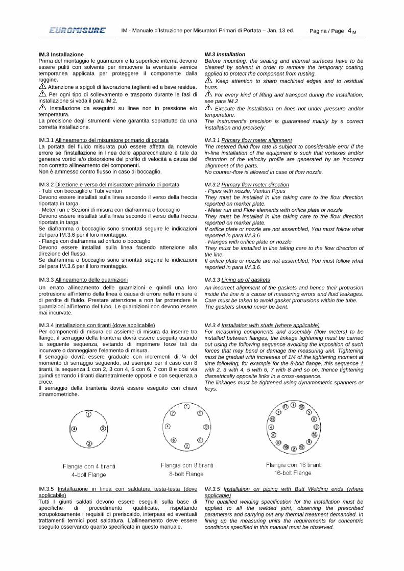
IM.3.4 Installazione con tiranti (dove applicabile) IM.3.4 Installation with studs (where applicable) Per componenti di misura ed assieme di misura da inserire tra flange, il serraggio della tiranteria dovrà essere eseguita usando la seguente sequenza, evitando di imprimere forze tali da incurvare o danneggiare l’elemento di misura. Il serraggio dovrà essere graduale con incrementi di ¼ del momento di serraggio seguendo, ad esempio per il caso con 8 tiranti, la sequenza 1 con 2, 3 con 4, 5 con 6, 7 con 8 e cosi via quindi serrando i tiranti diametralmente opposti e con sequenza a croce. Il serraggio della tiranteria dovrà essere eseguito con chiavi dinamometriche.
For measuring components and assembly (flow meters) to be installed between flanges, the linkage tightening must be carried out using the following sequence avoiding the imposition of such forces that may bend or damage the measuring unit. Tightening must be gradual with increases of 1/4 of the tightening moment at time following, for example for the 8-bolt flange, this sequence 1 with 2, 3 with 4, 5 with 6, 7 with 8 and so on, thence tightening diametrically opposite links in a cross-sequence. The linkages must be tightened using dynamometric spanners or keys.
IM.3.5 Installazione in linea con saldatura testa-testa (dove applicabile)
IM.3.5 Installation on piping with Butt Welding ends (where applicable)
Tutti I giunti saldati devono essere eseguiti sulla base di specifiche di procedimento qualificate, rispettando scrupolosamente i requisiti di preriscaldo, interpass ed eventuali trattamenti termici post saldatura. L’allineamento deve essere eseguito osservando quanto specificato in questo manuale.
The qualified welding specification for the installation must be applied to all the welded joint, observing the prescribed parameters and carrying out any thermal treatment demanded. In lining up the measuring units the requirements for concentric conditions specified in this manual must be observed.

IM - Manuale d’Istruzione per Misuratori Primari di Portata – Jan. 13 ed. Pagina / Page 5IM
IM.3.6 Installazione del componente di misura IM.3.6 Measuring component installation - Diaframma con foro calibrato Il diaframma di misura deve essere installato facendo attenzione alla direzione del flusso. Il diaframma e le guarnizioni non devono essere mai incurvati. Sia il diaframma che le guarnizioni devono essere centrati con l’asse del tubo. Il massimo errore di concentricità del diaframma deve essere ± 0.8 mm. Il centraggio delle guarnizioni può essere meno preciso di quello del diaframma, facendo attenzione a non far protendere le guarnizioni all’interno del tubo. Diaframmi aventi fori di sfiato o di spurgo, installati in linee orizzontali, devono avere la maniglia dell’elemento di misura posizionata sull’asse verticale. L’orientamento del foro di sfiato o di spurgo è automatico essendo questi fori in asse con la maniglia. L’elemento di misura deve essere installato secondo il senso del flusso marcato sulla rispettiva maniglia. Il lato a monte del diaframma è quello con lo spigolo vivo. Questo lato è identificato dalle parole “LATO ENTRATA” o “A MONTE” stampigliate sulla maniglia del diaframma o sul lato d’entrata del disco o da una freccia sulla targhetta (lo smusso del foro calibrato deve essere sempre posizionato a valle). Se questa raccomandazione non viene rispettata, la misura non sarà corretta e si renderà necessario lo smontaggio del diaframma. I diaframmi per uso bi-direzionale o quelli per i quali non è necessaria l’esecuzione dello smusso a valle possono non essere stampigliati. Si veda il disegno di riferimento In presenza di camere anulari prestare attenzione alle scritte “a monte” / “a valle” o “+” / “-“ per il loro corretto posizionamento. In ogni caso si veda il disegno di riferimento. - Boccaglio Il boccaglio deve essere installato facendo attenzione alla direzione del flusso. Il componente boccaglio ha il diametro a monte (entrata) maggiore rispetto al diametro a valle (gola). Per guarnizioni ed allineamento si veda il punto precedente (“Diaframma con foro calibrato”). In ogni caso si veda il disegno di riferimento.
- Orifice plate The orifice plate must be installed taking care to the flow direction. The orifice plate and the gaskets should never be bent. Both the orifice plate and the gaskets must be centred on the axis of the tube. The maximum error of concentric positioning of the orifice plate must be within ± 0.8 mm. The gaskets positioning may be slightly less critical than the orifice plate one, but care must be taken to avoid protrusion within the tube. Orifice plate with drain or vent holes, installed in horizontal lines, must have the handle of measuring unit positioned on the vertical axis. The orientation of the drain / vent holes is automatic since they are lined up with the handle. The measuring unit must be installed according to the flow direction marked on the corresponding handle. The upstream side of the orifice plate is the one with the sharp edge. This side is identified by the "INLET" or “UPSTREAM” word stamped on the handle or on the orifice plate inlet face or by an arrow on the marker plate (the orifice bevel must always be on downstream side). If this recommendation is not respected the flow measurement will be incorrect and the dismounting of the flow assembly will be necessary. The orifice plates intended for reverse flow or the ones where the bevel is not necessary as per Codes requirement may be not stamped. See reference drawing. In presence of annular chamber, take care to the words “upstream” / “downstream” or “+” / “-“ for a correct location. In any case see the reference drawing. - Nozzle The nozzle must be installed taking care to the flow direction. The nozzle component has the upstream diameter (inlet) greater than the downstream diameter (throat). For gaskets and positioning see the previous point (“Orifice plate”). In any case see the reference drawing.
IM.3.7 Coibentazione IM.3.7 Insulation
Dopo l’installazione è necessario rivestire il tubo con materiale isolante secondo le specifiche di linea. Per le linee vapore è necessario includere nella coibentazione anche le valvole, escludendo i barilotti di condensazione.
After installation it is necessary to spool the pipe with lagging thickness as required in specification For steam service the lagging will be made up to valves included, excluding the condensing pots.
IM.3.8 Tratti rettilinei IM.3.8 Straight-line lengths E’ di estrema importanza, al fine della precisione di misura, una corretta disposizione del misuratore sulla linea, prevedendo opportuni tratti rettilinei a monte ed a valle dell’elemento di misura. L’utilizzo delle Tabelle 1 e 2 danno indicazioni per una corretta installazione. Valvole, connessioni e altri componenti dovranno preferibilmente essere posizionati a valle del misuratore. In caso di ampia disponibilità di tratti rettilinei posizionare l’elemento di misura in modo che l’80% di tali tratti sia a monte ed il 20% a valle. L’utilizzo di raddrizzatori di filetti fluidi potrà essere considerato in quei casi dove non siano disponibili sufficienti tratti di tubo rettilinei. Quando possibile è consigliato di installare l’apparecchio di misura su tubazioni orizzontali. Generalmente le sezioni di misura / meter run hanno i tratti rettilinei a monte ed a valle già compresi nel misuratore di portata fornito, in ogni caso, per maggiori delucidazioni, contattare Euromisure.
it is extremely important, to ensure measurement with precision, to obtain a correct arrangement of the flow meter in the line, providing for straight-line lengths both before and beyond the measuring unit. Tables 1 and 2 give indications for a correct installation. Valves, joints and other components must preferably be positioned after the flow meter. Where there is a large availability of straight lengths, the flow meter must be positioned so that the 80% of these straight lengths come before and the other 20% after the unit. The use of straighteners (Flow conditioners) can be considered in those cases where there are not sufficient lengths of straight-line tubing. It is recommended where possible to install the measuring equipment on horizontal tubing. Generally flow elements / meter run have the upstream and downstream straight-line lengths already included in the supplied flow meter, in any case, for greater explanations, contact Euromisure.

IM - Manuale d’Istruzione per Misuratori Primari di Portata – Jan. 13 ed. Pagina / Page 6IM
REQUIRED STRAIGHT LENGTHS BETWEEN ORIFICE PLATES AND FITTING WITHOUT FLOW CONDITIONERS
REQUIRED STRAIGHT LENGTHS FOR NOZZLES AND VENTURI NOZZLES

IM - Manuale d’Istruzione per Misuratori Primari di Portata – Jan. 13 ed. Pagina / Page 7IM
REQUIRED STRAIGHT LENGTHS FOR CLASSICAL VENTURI TUBES

IM - Manuale d’Istruzione per Misuratori Primari di Portata – Jan. 13 ed. Pagina / Page 8IM
IM.3.9 Posizionamento delle prese di pressione IM.3.9 Positioning the pressure measuring points Per misuratori installati su linee orizzontali le prese di pressione dovranno essere disposte FLUIDI LIQUIDI: SEMICERCHIO INFERIORE GAS: SEMICERCHIO SUPERIORE VAPORE: ORIZZONTALI Posizione prese di pressione
For meters installed on horizontal lines the pressure taps must be located : LIQUID FLUIDS: LOWER SEMICIRCLE GAS: UPPER SEMICIRCLE STEAM: HORIZONTAL Pressure taps position
-+
- +
per liquidi
per gas
per vapore
Per misuratori installati su linee verticali e dove la temperatura del fluido differisce dall’ambiente di più di 10°C, un nipplo a “S” di dimensione minima DN ½” dovrà essere montato sulla presa superiore quando il fluido è saliente(fig. 2) e alla presa inferiore quando il fluido è discendente (fig. 1). La lunghezza del nipplo ad “S” sarà tale da portare allo stesso livello del nipplo orizzontale collegato all’altra presa.
For meters installed on vertical lines and where the temperature of the fluid differs by more than 10° from that of the surroundings, an "S" nipple with minimum dimensions Ø 1/2" must be mounted on the pressure tap when the fluid is rising (Fig. 2) and on the lower pressure tap when the fluid is descending (Fig. 1). The length of the "S" nipple will be such as to arrive at the same level as the horizontal nipple connected to the other flange
Fig.: 1 Fig.: 2 IM.3.10 Stato delle tubazioni collegate a monte ed a valle del misuratore
IM.3.10 Condition of the tubing connected above and below the flow meter
La superficie interna del tubo che precede e segue il misuratore dovrà essere priva di scaglie, incrostazioni e fori per almeno 10 diametri a monte e 4 a valle dell’elemento di misura il tubo a monte per almeno 2 D dalla faccia dell’elemento di misura dovrà essere cilindrico in modo che nessun diametro misurato non superi dello 0.3% il valore medio per diaframmi e boccagli e dell’1% per i Venturi. Nessun diametro del tubo a valle per una lunghezza pari a 2 D dalla faccia a monte del componente di misura deve differire del 3% del valore medio del tubo a monte. Se per assicurare questi gradi di concentricità si dovessero alesare i tubi, l’alesatura si dovrà estendere come minimo a 2 D a monte ed a valle dalla faccia di entrata dell’elemento di misura. La parte alesata dovrà raccordarsi con la parte non alesata con un angolo massimo di 30°. La profondità di alesatura dovrà essere la minima per ottenere le condizioni desiderate. L’alesatura si dovrà effettuare dopo la saldatura di flange o altri componenti. Dopo la saldatura si dovrà molare ogni sporgenza del cordone di saldatura all’interno del tubo.
The internal surface of the tube before and after the flow meter must be free from burrs, deposits and holes for at last 10 diameters before and 4 after the measuring unit. The tubing before for at least 2 D from the face of the measuring unit must be cylindrical so that no measured diameter differs from the average value by more than 0.3% for orifice plate and nozzles or by 1% for Venturi Nozzle tubes. No downstream pipe diameter, for a length of 2 D from the upstream side of the measure unit, must differ by 3% from the average value of upstream pipe diameter. If, in order to guarantee these degrees of concentric conditions, it is necessary ream out the tubing, reaming must be taken at the minimum to 2 D above the inlet face of the measuring unit. The reamed-out part must be coupled to the non-reamed part with an angle not exceeding 30°. The depth of reaming must be kept to the minimum to obtain the required conditions. Reaming should be carried out after the welding of flanges or other components. After welding any residue or projection from the welding inside the tube should be ground away.
IM.3.11 Connessione agli strumenti trasmettitori / indicatori / registratori
IM.3.11 Connection to transmitters / indicator / recorder instruments
Per applicazioni con fluidi ad alta temperatura i nippli e/o tubi di collegamento allo strumento dovranno essere di spessore adeguato alle condizioni di servizio e dovranno avere una lunghezza tale da assicurare che la temperatura allo strumento non superi 250°F (120°C) o altro valore suggerito dal costruttore dello strumento (300 mm di tubo inox rappresenta un raffreddamento di 100°F).
Installazioni all’aperto potrebbero richiedere un riscaldamento del fluido passante nei tubi di collegamento per prevenire il congelamento.
Le linee di collegamento dovranno essere inclinate e dovranno essere supportate per prevenire vibrazioni. Si dovranno evitare curvature brusche operando curve di raggio almeno 3 volte il diametro esterno del tubo. Le due linee di collegamento (+ e -) dovranno essere disposte ravvicinate per mantenerle alla stessa temperatura. Sono da evitare tubi di collegamento in nylon o plastiche in presenza di
For applications with high temperature fluids the nipple and / or tubes connecting to the instrument must be wide enough for the working conditions and must be long enough to ensure that the temperature at the instrument never exceeds 250° F (120°C) or other value recommended by the instrument manufacturer . (1 foot of stainless steel tubing represents a cooling of 100°F).
Installation outdoors may require heating of the fluid being passed in the connecting tubes to prevent freezing.
The connecting lines must be tilted and must be supported to prevent vibration. Abrupt bending is to be avoided with the use of curves having a radius at last 3 times the external diameter of the tube. The two connection lines (+ and -) must be placed close together to keep them at the same temperature. Avoid using nylon or plastic connecting tubes together with high-temperature tubing or sources of heat. The connecting lines must be airtight.

IM - Manuale d’Istruzione per Misuratori Primari di Portata – Jan. 13 ed. Pagina / Page 9IM
tubazioni ad alta temperatura o fonti di calore. Le linee di collegamento dovranno essere a tenuta d’aria. L’isolamento dello strumento di misura dovrà essere fatto con valvole di radice e/o valvole manifold. Lo strumento dovrà essere posizionato come segue: LIQUIDI: Sotto il misuratore VAPORE: Sotto il misuratore e tramite barilotti di condensa GAS: Sopra il misuratore I barilotti di condensa devono essere allineati sullo stesso piano orizzontale (in caso di linee verticali, con la presa inferiore in caso di flusso discendente e con la presa superiore in caso di flusso saliente).
The measuring unit is to be shut-off using root valves and/or manifold valves. The instrument must be arranged as follows : LIQUIDS: Below the meter STEAM : Below the meter through condensation chambers GAS: Above the meter Condensing pots must be in the same horizontal position ( lower pressure taps level when the fluid is rising, upper pressure taps level when the fluid is descending, in case of vertical lines ).
ESEMPI DI INSTALLAZIONE ASSEMBLING EXAMPLES
PER APPLICAZIONI SU LIQUIDI FOR LIQUIDS
PER APPLICAZIONI SU GAS FOR GAS
PER APPLICAZIONI SU VAPORE FOR STEAM
PER APPLICAZIONI SU VAPORE (TEMPERATURA SOPRA 455°C) FOR STEAM WITH TEMPERATURE OVER 455°C
MISURATORE Flow Device
p-CELL
MANIFOLD
MISURATORE Flow Device
p-CELL
MANIFOLD
MISURATORE Flow Device
MANIFOLD
p-CELL
BARILOTTO Seal Pot
MISURATORE Flow Device
MANIFOLD
p-CELL
BARILOTTO DI CONDENSA Condensing Pot
MISURATORE Flow Device
MANIFOLD
p-CELL
MISURATORE Flow Device
MANIFOLD
p-CELL
BARILOTTO DI CONDENSA
Condensing Pot
MISURATORE Flow Device
MANIFOLD
p-CELL
BARILOTTO DI CONDENSA
Condensing Pot
BARILOTTO DI CONDENSA Condensing Pot
MISURATORE Flow Device
COIBENTAZIONE Lagging

IM - Manuale d’Istruzione per Misuratori Primari di Portata – Jan. 13 ed. Pagina / Page 10IM
IM.3.12 Dispositivi forniti e Accessori aggiuntivi IM.3.12 Supplied devices and additional equipments •Se non previsto nel progetto e non realizzato dal costruttore, nessun dispositivo per la chiusura o l’apertura è applicabile direttamente al pezzo fornito. Non è possibile l’ispezione interna in assenza di tale dispositivo. •Nessun dispositivo è previsto per: - limitazione di pressione (valvole di sicurezza, ec.) - regolazione e controllo di pressione e temperatura (“pressure
switches”, “temperature switches”, sistemi di misura) - allarmi •In funzione della temperatura di servizio è necessaria una opportuna protezione per evitare contatti accidentali da parte del personale. I dispositivi e le protezioni sopra riportati non sono inclusi nella fornitura, ma, per rispettare i requisiti di sicurezza, la necessità e le modalità di installazione devono essere valutate dall’utente. Tutti i componenti installati in post vendita devono essere rispondenti alle vigenti norme e direttive di prodotto e devono essere montati secondo le stesse.
•If it is not provided in the design and not executed by the manufacturer, no devices for closing and opening are directly applicable to the supplied material. It’s not possible the inside inspection without this device. •No devices are provided for: - pressure limitation (safety valves, etc.) - pressure and temperature regulation and control (pressure
switches, temperature switches, measurement devices) - alarms •Due to the service temperature a suitable protection is necessary to avoid the personnel accidental contacts. The above listed devices and protections are not included in the scope of supply but, in order to respect the safety requirements, the necessity of their installation have to be valued by user. All after market installed parts should be in compliance with the regulations and directives in force and be jointed according to the same.
IM.4 Avviamento IM.4 Start up
Durante le fasi di avviamento dell’impianto in caso di flussaggio delle linee si deve estrarre l’elemento di misura, ad es. il disco con orifizio, o montare un pezzo distanziatore (Attenzione: operazioni da eseguirsi su linee non in pressione e/o temperatura) o porre l’elemento su linee di By-pass per evitarne il danneggiamento. Durante tali fasi le prese di pressione devono essere tappate per evitare che la sporcizia affluisca agli strumenti. Al termine del flussaggio si deve inserire l’elemento di misura ripristinando il centraggio e si devono pulire le prese di pressione.
Before the fluxing of the lines the measuring unit must be extracted, for ex. the orifice plate, or a spacer piece must be mounted (Attention: execute these operations only on no pressure and/or temperature lines) or set on by-pass lines to avoid its damage. During this phase the pressure taps must be plugged to avoid flow of dirt into the instruments. When fluxing has terminated the measuring unit must be replaced and centred again and the pressure points must be cleaned.
IM.4.1 Istruzioni di pre-avviamento IM.4.1 Pre-start instructions Durante le fasi di avviamento si dovranno riempire le linee di misura, se possibile, per mezzo di linee di By-pass, ed in tali fasi le valvole di radice dovranno essere chiuse. Durante le fasi di riempimento si dovrà porre cura per evitare colpi di ariete che possano danneggiare gli elementi di misura. Raggiunto il regime stabile di flusso di portata si riempiranno i tubi di collegamento allo strumento
During the start-up phase the measuring lines must be filled if possible by means of by-pass lines. In such phases the root valves of the meter must be closed. During the filling phase care must be taken to avoid water hammering which may damage the measuring units. When a steady flow state is reached the connecting tubes for the instrument are filled.
IM.4.2 Istruzioni di Avviamento - Azzeramento dello strumento IM.4.2 Start-up instructions - Zero set-up of the instrument Prima di esporre lo strumento alla pressione di linea, controllare la calibrazione dello zero (senza condensa nelle linee di collegamento e con le valvole + e - chiuse). A questo punto lo strumento dovrà essere collegato all’alimentazione elettrica o pneumatica. Il segnale dello strumento dovrà essere di 4 mA per strumenti alimentati elettricamente e 3 PSI per strumenti alimentati ad aria. Servizio con Liquidi e Vapori 1 Prima di avviare assicurarsi che le valvole di radice e la
valvola di By-pass siano chiuse. 2 Con le valvole + e - chiuse, aprire valvola di By-pass, ed
aprire lentamente la valvola –. 3 Aprire gli sfiati per fare uscire l’aria dai condotti. 4 Chiudere gli sfiati. 5 Aprire lentamente gli sfiati sullo strumento aspettando che
fuoriesca il fluido liberamente. 6 Battere delicatamente il corpo dello strumento, delle valvole
e/o del manifold e dei tubi di connessione per far fuoriuscire ogni bolla d’aria.
7 Ripetere il passo 3. 8 ripetere il passo 5 e 6. 9 Aprire lentamente la valvola +. 10 Ora il sistema è operativo. Servizio con Gas 1 Prima di avviare assicurarsi che le valvole di radice e la
valvola di By-pass siano chiuse. 2 Con le valvole + e - chiuse, aprire valvola di By-pass, ed
aprire lentamente la valvola. 3 Aprire gli spurghi per far fuoriuscire la possibile condensa
presente nei condotti. 4 Chiudere gli spurghi e la valvola di by-pass. 5 Aprire lentamente la valvola +. 6 Ora il sistema è operativo.
Before exposing the instrument to the pressure in the line, check the zero calibration (without condensation in the connecting lines and with the + and - valves closed). At this point the instrument must be connected to the electrical or pneumatic line feed. The reading on the instrument should be 4 mA for electric instruments and 3 PSI for pneumatic instruments. Liquid and Steam service 1 Before starting check if the root valves and by-pass valves
are closed. 2 With the + and - valves closed, open the by-pass valve and
then slowly open the - valve. 3 Open the vent valves to clear the air from the pipes. 4 Close the vent valves. 5 Slowly open the vent valves on the instrument until the fluid
escapes freely 6 Lightly tap the body of the instrument, the valves and/or the
manifolds and the connecting tubes to get out all the air bubbles.
7 Repeat step 3. 8 Close the vent valves and the by-pass valve. 9 Slowly open the + valve. 10 The system is now operative. Gas service 1 Before starting check if the root valves and by-pass valves
are closed. 2 With the + and - valves closed, open the by-pass valve.
Slowly open the – valve. 3 Open the drain valves to expel any condensation there may
be in the pipes. 4 Close the drain valves and by-pass valve. 5 Slowly open the + valve. 6 The system is now operative.

IM - Manuale d’Istruzione per Misuratori Primari di Portata – Jan. 13 ed. Pagina / Page 11IM
IM.5 Prova idrostatica in linea IM.5 In line hydrostatic test Prova idrostatica da eseguirsi con fluido (acqua) a temperatura non inferiore a quella minima di progetto riportata in targa e comunque non inferiore a 5°C. Non eseguire prova idrostatica con temperatura di parete inferiore a quella minima di progetto. Rispettare la pressione di prova idrostatica del progetto ed in ogni caso quella riportata in targa.
Hydrostatic test with fluid (water) at a temperature not below to the minimum design temperature reported on the marker plate and in any case not below to 5°C. Don’t carry out the hydrostatic test with wall temperature below the minimum design one. Don’t exceed the hydrostatic pressure of the project and in any case that on the marker plate.
IM.6 Istruzioni operative IM.6 Operating instructions
Non è ammesso contro flusso in caso di tubi con boccaglio. Durante le normali condizioni operative i condotti di collegamento allo strumento devono essere sfiatati o spurgati.
Durante il servizio la pressione e temperatura devono essere sempre controllate e non devono superare i valori di progetto indicati in targa.
La purezza, lo stato e la velocità del fluido devono essere controllati ed in ogni caso devono essere tali da non causare danni al pezzo. Anche l’azzeramento dello strumento deve essere controllato.
I misuratori non sono progettati per il fuoco esterno. Istruzioni per la fermata Per fermare il processo di misura seguire la seguente procedura: 1 Aprire la valvola di By-pass. 2 Chiudere le valvole + e –. 3 In caso di misuratori su linee di By-pass, aprire la valvola di
linea e chiudere la valvola di By-pass.
No counter-flow is allowed in case of flow nozzle tube. During normal service the connecting pipes for the instrument must be vented or drained.
During the service the pressure and the temperature have to be continuously checked and they can not be exceeded the design values indicated on marker plate.
The pureness, the condition and the velocity of the fluid must be monitored and they must be not dangerous for the part. Also the zero set-up of the instrument must be checked.
The primary flow meters are not designed for the external fire. Stop instructions. To stop the measuring process follow the procedure listed below: 1 Open the by-pass valve. 2 close the + and – valves. 3 When the measuring units are on by-pass lines, open the line
valve and close the by-pass valve.
IM.7 Manutenzione IM.7 Maintenance
Attenzione: Non operare su misuratori primari di portata in pressione e/o temperatura montati sia su linee di by-pass che su linee principali. Attenzione ai fluidi contenuti. I misuratori a pressione differenziale sono virtualmente privi di manutenzione.
Si consiglia una ispezione periodica in cui riscontrare lo stato di conservazione delle superfici esterne e delle tenute. In caso il misuratore (ad es. flangia ad orifizio) richieda una pulizia si dovrà procedere come segue: 1 Rimuovere l’elemento di misura, 2 Soffiare le parti con aria compressa, 3 Pulire con solventi utilizzando panni morbidi, 4 Controllare lo stato delle prese di pressione, 5 Pulire i passaggi delle prese di pressione con tasselli di legno
o tondi in materiali teneri. 6 Pulire i condotti allo strumento con aria compressa o getti
d’acqua, 7 Sostituire le guarnizioni, 8 Controllare se ci sono parti soggette a corrosione
ripristinando le protezioni superficiali, 9 Controllare l’integrità delle connessioni saldate o filettate, 10 Ripristinare i serraggi. Per le operazioni di manutenzione non sono richiesti / previsti attrezzi speciali.
Attention: don’t work on primary flow meter under pressure and/or temperature mounted both on by-pass lines and on principal lines. The differential pressure measuring units require practically no maintenance.
It is recommended that an inspection of the state of the external surface and of the seals be carried out periodically. Should the measuring unit require cleaning the procedure below be followed : 1 Remove the measuring unit 2 Use compressed air to blow the parts 3 Clean with solvents using soft cloths 4 Check the condition of the pressure taps 5 Clean the passages of the pressure taps with wooden dowels
or soft metal rods 6 Clean the tubing of the instrument with compressed air or jets
of water 7 Change the gaskets 8 Check whether there are parts affected by corrosion and
renew the surface protections 9 Check weld and screw connections 10 Check the tightening surface No special equipment or tools are required or provided for maintenance operations.
IM.8 Assistenza IM.8 Assistance
Per condizioni in cui si richiede la sostituzione o la riparazione dei componenti si dovrà contattare l’officina EUROMISURE al seguente indirizzo:
For those conditions requiring the substitution or repair the components, EUROMISURE workshop should be contacted at the following address:
Via G. Borghisani, 4 26035 PIEVE S. GIACOMO (CR) ITALY Tel.: +39-0372-6404 Fax: +39-0372-640490 e-mail: [email protected]
È’ vietato qualsiasi tipo di riproduzione totale o parziale del presente manuale. Edizione Gennaio 2013.
It’s forbidden every kind of total or partial reproduction of this manual. January 2013 edition.