Embed Size (px)
Citation preview

Characterization of Multi-Porosity
Unconventional Reservoirs and their Relationship to Oil and Gas Productivity
Roberto Aguilera,
CNOOC Nexen Chair on Tight Oil and Unconventional Gas Schulich School of Engineering,
University of Calgary March 10, 2015

OBJECTIVES
Discuss multi-porosity unconventional reservoirs.
Show that there is a continuum that goes from conventional to tight gas to shale gas to tight oil
to shale oil reservoirs Relate pore throat apertures to oil and gas rates
in vertical and horizontal wells. Make the work tractable by using actual
published data.
Slide 2
Multi-Porosity • Unconventional Reservoirs 2

A multidisciplinary integration of:
Geoscience (G) Formation evaluation (F)
Reservoir drilling, completion and stimulation (R) Reservoir engineering (RE)
Economics and externalities (EE)
Focus is on increasing production rates and ultimate recoveries economically and responsably from tight oil and unconventional gas reservoirs
GFREE
3

Dual-porosity Triple-porosity Multi-porosity in shales Effect on water saturation Flow units: from conventional , to tight gas, to
shale gas, to tight oil, to shale oil, to condensate reservoirs
Link of petrophysics with decline analysis Conclusions
OUTLINE
4
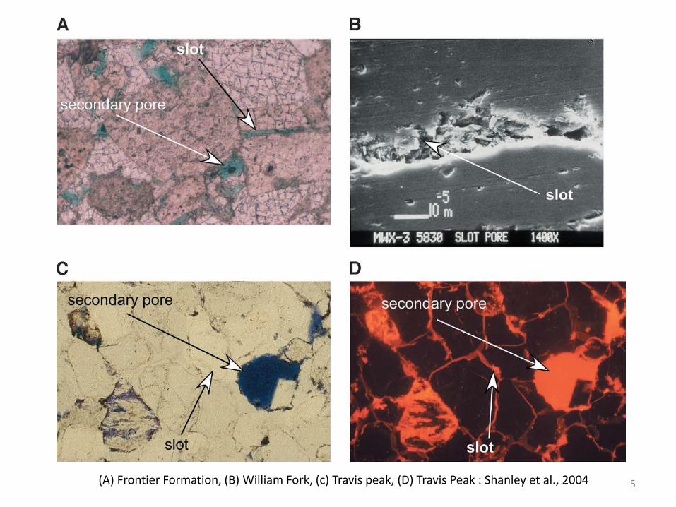
(A) Frontier Formation, (B) William Fork, (c) Travis peak, (D) Travis Peak : Shanley et al., 2004
5

Cadomin Fm. - Elmworth Deep Basin (7-23-69-13W6)
(Moslow, 2005)
microfracture cross-cutting clasts and sandy matrix
2
3 slot
1
Intg. Ø
Flourescence
2660.m Ø=5.0%, Kmax=24mD
6
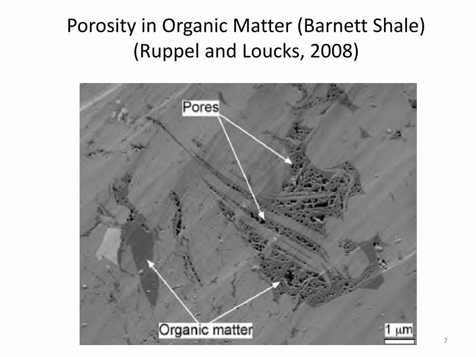
Porosity in Organic Matter (Barnett Shale) (Ruppel and Loucks, 2008)
7

Porosity in Organic Matter
SEM Imaging , thin section Colorado Shale (courtesy D. Rokosh, ERCB, SPE 137795)
COLORADO SHALE (CANADA)
8

DUAL POROSITY Matrix and Fractures
(or Matrix and Slot Porosity)
9
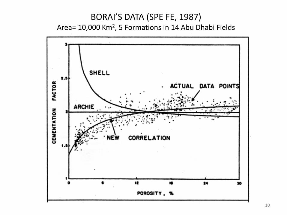
BORAI’S DATA (SPE FE, 1987) Area= 10,000 Km2, 5 Formations in 14 Abu Dhabi Fields
10
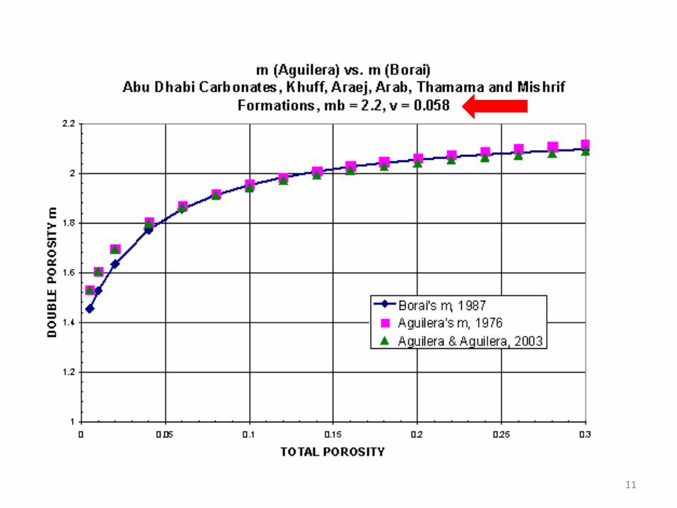
11

Porosity Exponent m, Mesa Verde Formation, USA (Data Source: Byrnes et al., Kansas Geological Survey, 2006)
Fit Using Dual Porosity Model (Matrix and Slots)
1.3
1.4
1.5
1.6
1.7
1.8
1.9
2
2.1
0.00 0.02 0.04 0.06 0.08 0.10 0.12 0.14 0.16 0.18
Routine Porosity
Arc
hie
cem
enta
tion
expo
nent
m
Core Dataphi2=0.002, mb=1.75phi2=0.001, mb=1.86phi2=0.0007, mb=1.97
12

POSTDAM (CAMBRIAN), QUEBEC, mb=1.77, mf = 1.2, φ2 = 0.65%
1.0
1.5
2.0
0.00 0.02 0.04 0.06 0.08 0.10TOTAL POROSITY
DU
AL-
POR
OSI
TY E
XPO
NEN
T, m
Core Data
Dual-phi Model
13 SPE114174

f
f
b2
2
1'
φ
φφφ
−
−=
2lnln)1(φφ
−−= ff mmf
φφφφ
log}'/])(1[){(
1log
−
−+=
− bff mb
mm vvm
Dual Porosity Model (Matrix and Fractures), mf = 1.0 or >1.0 Source: Aguilera, SPE 114174, 2008
m = porosity exponent of composite system of matrix and fractures
mb = porosity exponent of the matrix Ø = total porosity, fraction
Øb = matrix porosity of unfractured plug, fraction Ø2 = fracture porosity = v Ø, fraction
v = partitioning coefficient
Last equation valid for φ2 greater than zero 14

CHART FOR EVALUATING NATURALLY FRACTURED RESERVOIRS (mb=2.2)
1.0
1.2
1.4
1.6
1.8
2.0
2.2
0.00 0.10 0.20 0.30 0.40 0.50 0.60 0.70 0.80 0.90 1.00
MATRIX POROSITY, φb
DU
AL
POR
OSI
TY E
XPO
NEN
T, m
TOTAL POROSITY, φ4 8 12 16 20 24 28 30 35 40 45 50 60 70 80 90 99.99
v=0.058
v=0.10
v=0.20
v=0.30
v=0.40
v=0.50
v=0.70
v=0.90
(Aguilera, 2003) 15
mf =

TRIPLE POROSITY Matrix, Fractures and Non-Effective Porosity
SILICICLASTICS
16

Schematic of Triple Porosity Model (Source: Al Ghamdi et al., SPE 132879, 2010)
Non touching vugs (or non-effective porosity)
Fractures
Matrix
17

Tight Gas Sand Petrography courtesy of ConocoPhillips 18

Triple Porosity Model (nomenclature as in previous equations)
2
2
(1 )log(1 ) /
log
b
ncnc m
bvm
φφφ φ φ
φ
−
−− + + − =
Al Ghamdi et al, SPE 132879
19
m = porosity exponent of triple porosity system
mb = porosity exponent of the matrix Ø = total porosity, fraction
Øb = matrix porosity of unfractured plug, fraction Ønc = non-connected (or isolated) porosity = vnc Ø, fraction
vnc = vug porosity ratio

20
TRIPLE POROSITY MODEL, mb = 2.0 m

Shales: Multiple Porosity Rocks
• (1) adsorbed gas into the kerogen material • (2) free gas trapped in nonorganic inter-particle
(matrix) porosity • (3) free gas trapped in microfracture porosity • (4) free gas stored in fractures created during
stimulation of the shale reservoir • (5) free gas trapped in a pore network developed
within the organic matter or kerogen
21

Porosities in Shales SPE 171638, 2014
22
φφφφ
log/)1(
)1(logker22
2ker
ker
−−+−
+−
=− bm
bt
tt V
VVm
m = porosity exponent (multiple porosities)
mb = porosity exponent of the matrix Ø = total porosity, fraction
Øb = matrix porosity scaled to bulk volume of the matrix, fraction Vtker = total volume of kerogen = Øorg+Øads+Vdiff, fraction

Slide 23
Modified Pickett crossplot including variable values of m calculated with multiple porosity model (SPE 171638)
Zone 1: φ = 5%, φm = 3.9%, φ2= 0.63%, φorg = 0.9%, φads = 0.2%
Passey
23

MATERIAL BALANCE APPLICATION (Lopez and Aguilera, SPE 165681, 2013)
Contribution of free gas, adsorbed gas and diffusion gas from kerogen to total cumulative gas production in Devonian shale gas reservoirs (Appalachian Basin)
Slide 24
24

FLOW UNITS: FROM CONVENTIONAL TO TIGHT GAS TO
SHALE GAS TO TIGHT OIL TO SHALE OIL RESERVOIR
(THERE IS A CONTINUUM)
25

FLOW UNIT
A flow unit is defined as a stratigraphically continuous reservoir subdivision characterized by a similar pore type (Hartmann and Beaumont, 1999), for example by a similar rp35
(Aguilera, 2002):
rp35=2.665 (k/100φ)^0.45
Slide 26
Multi-Porosity • Unconventional Reservoirs 26

Conventional vs. Continuous Type Accumulations (Used mostly to Explain Tight Gas)
(Pollastro and Schenk; 2002, Moslow, 2008)
Slide 27
Multi-Porosity • Unconventional Reservoirs 27

Real Data Conventional and
Low Permeability Rocks
Slide 28
Multi-Porosity • Unconventional Reservoirs 28
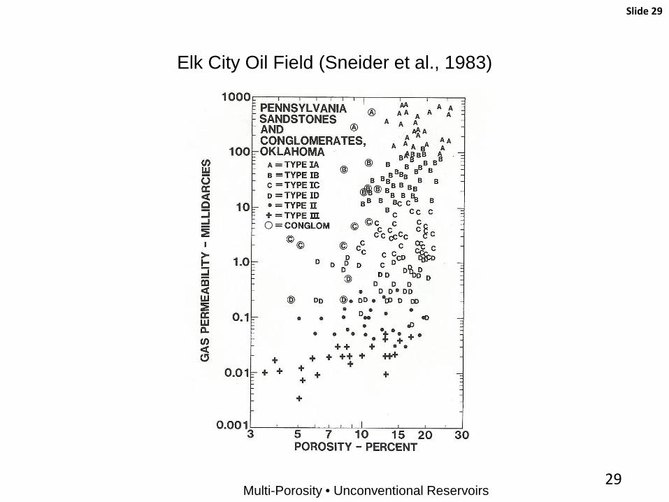
Elk City Oil Field (Sneider et al., 1983)
One-Column Format
Slide 29
Multi-Porosity • Unconventional Reservoirs 29

Unconventional Reservoirs, Elk City Oil Field (SPE 165350, 2013) Data from Sneider et al., 1983
One-Column Format
Slide 30
Multi-Porosity • Unconventional Reservoirs 30

Unconventional Reservoirs (Elk City Oil Field) Slide 31
Sneider et al, 1983 Multi-Porosity
Multi-Porosity • Unconventional Reservoirs 31

Unconventional Reservoirs, Cardium SS, Pembina Oil Field (Source of Data: MacKenzie, 1975)
Slide 32
Multi-Porosity • Unconventional Reservoirs 32

Slide 33
Multi-Porosity • Unconventional Reservoirs
Real Data Shale Gas
33

Flow Units
34

Unconventional Reservoirs: Shale Gas (SPE 132845)
Slide 35
Multi-Porosity • Unconventional Reservoirs 35

Slide 36
Multi-Porosity • Unconventional Reservoirs
Real Data Shale Gas and Tight Gas
36

Unconventional Reservoirs: Shale Gas and Tight Gas (SPE 132845)
One-Column Format
Slide 37
Multi-Porosity • Unconventional Reservoirs 37

Flow Units
GFREE RESEARCH PROJECT
38

Slide 39
Multi-Porosity • Unconventional Reservoirs
Real Data Tight Oil
39

Unconventional Reservoirs: Bakken Tight Oil
One-Column Format
Slide 40
Multi-Porosity • Unconventional Reservoirs 40

Unconventional Reservoirs, Cardium SS, Pembina Oil Field (Source of Data: MacKenzie, 1975; Hamm and Struyk, 2011)
Slide 41
Multi-Porosity • Unconventional Reservoirs 41

Unconventional Reservoirs: Tight and Shale
One-Column Format
Slide 42
Multi-Porosity • Unconventional Reservoirs 42

Flow Units
1.0E-12
1.0E-11
1.0E-10
1.0E-09
1.0E-08
1.0E-07
1.0E-06
1.0E-05
1.0E-04
1.0E-03
1.0E-02
1.0E-01
1.0E+00
1.0E+01
0 2 4 6 8 10 12 14 16
PER
MEA
BILI
TY (M
D)
POROSITY
FHR, B SOFT SHALES
0.040.0250.014
rp35microns0.55
NIKANASSIN
0.15MARCELLUS
HURON
BC CANADA
CRUSHED SAMPLES?
0.004
UTICA
UTICA
B.DEL
B.FW
B.M1H
0.0005
0.00005
GFREE RESEARCH PROJECT
43

Slide 44
Multi-Porosity • Unconventional Reservoirs
Theoretical Data Pore Scale Modeling
44

Flow Units (Pore Scale Modeling)
Rahmanian et al., SPE 133611 Microsimulation at the pore throat level: • Pore throat radii • Permeability • Porosity • Relative perms • Cap pressures • Electrical properties • Rock Mechanics • Stimulation • Prod allocation in commingled completions
GFREE RESEARCH PROJECT
Knudsen Number
Viscous Flow
Diffusion Dominated Flow
45
Microsimulation at the pore throat
level will supplement
results of rp, k, phi, rel perms, cap pressures,
electrical properties, rock
mechanics
Brittle? Ductile? Type of
Stimulation? Effect of Sw,
mud Filtrate, leak-off on embedment?
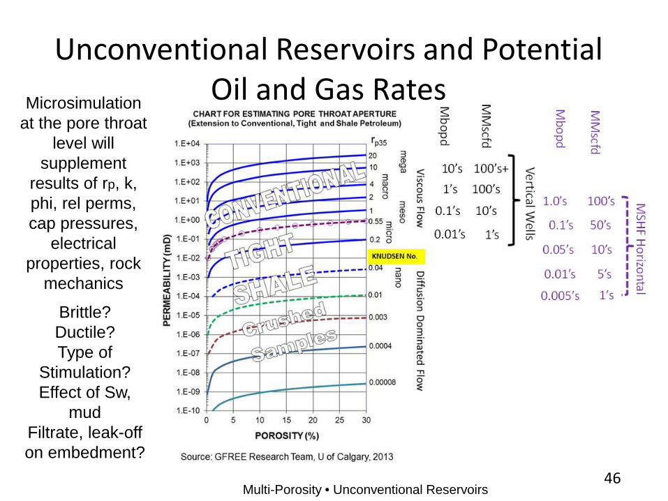
Unconventional Reservoirs and Potential Oil and Gas Rates
Multi-Porosity • Unconventional Reservoirs 46

Microsimulation at the pore throat
level will supplement
results of rp, k, phi, rel perms, cap pressures,
electrical properties, rock
mechanics
Brittle Ductile Type of
Stimulation Effect of Sw,
mud Filtrate, leak-off on embedment
Unconventional Reservoirs and Potential Oil and Gas Rates
Multi-Porosity • Unconventional Reservoirs
Conden-sate
47

OIL RATE VS. rP35 (Source of rate data: Martin, Solomon and Hartmann, 1997)
(Source of rp35 data: Aguilera, 2002-2003)q = 295.87(rp35)
1.4703
R2 = 0.9992
0.1
1
10
100
1000
10000
0.01 0.1 1 10
PORE THROAT APERTURE rP35
© Servipetrol, Dr. Roberto Aguilera, 2004
OIL
RA
TE, B
/D
Publishedsources
Best fit
Gaspe HTD potential / well ˜ 120 BOPD
HTD
r p35
˜ 0
.3 to
1.5
μm(or gas equivalent)
48
Vertical Well

OIL RATE VS. rP35 (Source of rate data: Martin, Solomon and Hartmann, 1997)
(Source of rp35 data: Aguilera, 2002-2003)q = 295.87(rp35)
1.4703
R2 = 0.9992
0.1
1
10
100
1000
10000
0.01 0.1 1 10
PORE THROAT APERTURE rP35
© Servipetrol, Dr. Roberto Aguilera, 2004
OIL
RA
TE, B
/D
Publishedsources
Best fit
Gaspe HTD potential / well ˜ 120 BOPD
HTD
r p35
˜ 0
.3 to
1.5
μm(or gas equivalent)
49
JUNEX PRESS RELEASE, Feb 23, 2015: 316 BOPD Non-stimulated horizontal well, Forillon Formation

PETROPHYSICAL DUAL, TRIPLE AND MULTIPLE POROSITY MODELS DISCUSSED PREVIOUSLY
CAN BE LINKED TO OIL AND GAS PRODUCTIVITY
50

Linear Flow in a Dual-Porosity Reservoir towards a Hydraulic Fracture of Infinite Conductivity
(Adapted from Aguilera, SPE 16442, 1987)
51

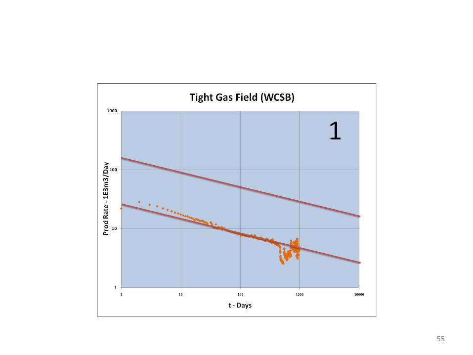
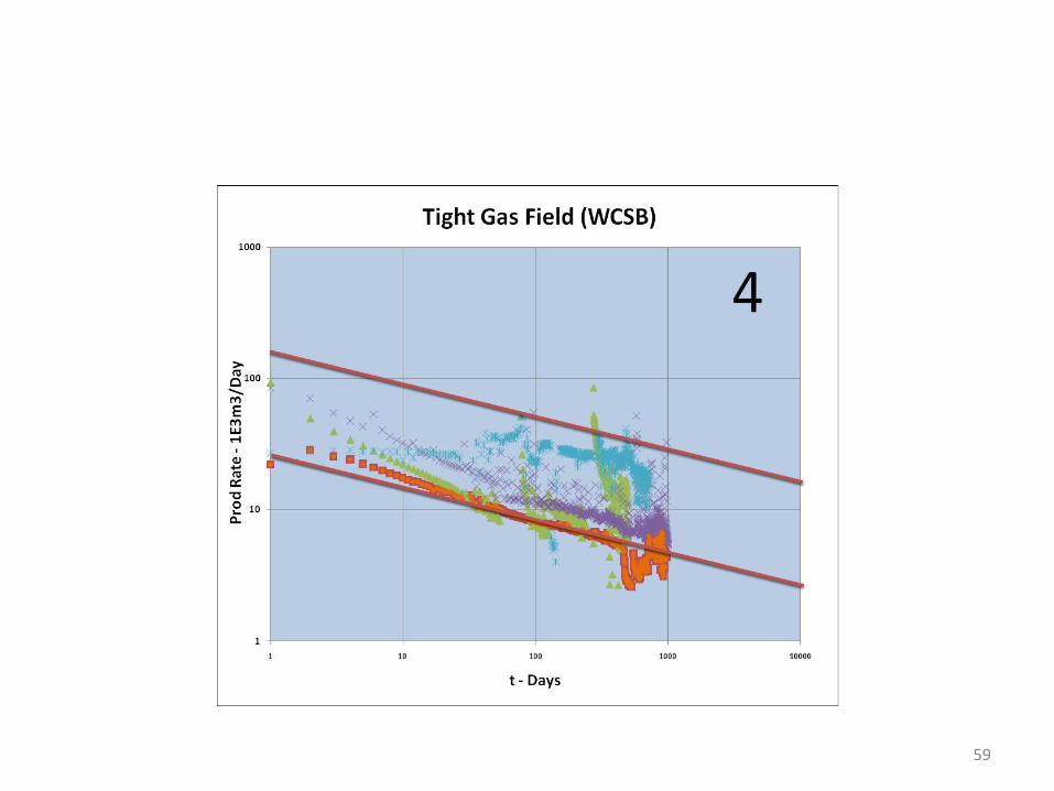
DECLINE ANALYSIS IN INFINITE-ACTING TRIPLE POROSITY RESERVOIR WITH RESTRICTED INTERPOROSITY FLOW DOMINATED BY LINEAR/BILINEAR FLOW
(Leguizamon and Aguilera, SPE 142727, 2011)
52
qD = dimensionless rate, tD = dimensionless time, w = storativity ratio, f = function, cc = commingled completion exponent, d = dual, t= triple

Infinite-Acting Linear Reservoir with Restricted Interporosity Flow
53
-0.5

Infinite-Acting Reservoir with Unrestricted Interporosity Flow
54
-0.5
55

56

57

58
59

60

61

62

63

64

65

Tight Gas Field, Well i1
66

Triple Porosity q Decline Commingled Completion Production Matching
1.E+03
1.E+04
1.E+05
1.E+06
1.E+01 1.E+02 1.E+03 1.E+04 1.E+05
q, m
3 / d
Time, hours
Well 1
Measured Rate Calculated rateHistory Matching Well 2
67
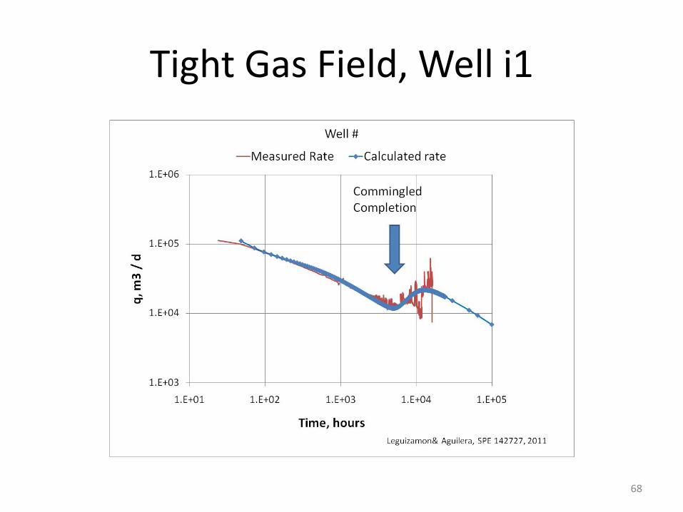
Tight Gas Field, Well i1
68

Tight Gas Field, Well i3
69

Tight Gas Field, Well i3
70
BDF

Slide 71
Inter-linear Flow Period
Multi-Porosity • Unconventional Reservoirs 71

Slide 72
1.E-06
1.E-05
1.E-04
1.E-03
1.E-02
1.E-01
1.E+00
1.E+01
1.E+02
1.E+03qD
tD
Decline Rate with Unrestricted Inter-Linear Transition FlowTriple Porosity Model Dominated by Linear Flow
Linear Flow (slope = -0.5)
Unrestricted Transition (slope ∼ -0.75)
Linear
Transition
Linear
Multi-Porosity • Unconventional Reservoirs 72

73 Hamm and Struik (2011)

Slope – 0.75
Slide 74
Multi-Porosity • Unconventional Reservoirs 74

Slope – 0.75
Slide 75
Multi-Porosity • Unconventional Reservoirs 75

Conclusions
• Multi-porosity models allow integration of petrophysical and production decline analysis and provide input data for material balance (and simulation) studies.
• There is a continuum between conventional gas, tight gas and shale gas reservoirs (same for oil reservoirs).
76

Acknowledgements
Paper # • Paper Title • Presenter Name
CNOOC NEXEN GFREE Research Team
Schulich School of Engineering at U of C Servipetrol Ltd.
Slide 77
Multi-Porosity • Unconventional Reservoirs 77

Thank You Paper # • Paper Title • Presenter Name
Slide 78
Multi-Porosity • Unconventional Reservoirs 78