Embed Size (px)
Citation preview

M s e r i e s m o t o r s
C H A R A C T E R I S T I C S O F T H E M S E R I E S M O T O R S
Motormodel
Displacement (cc/rev)
Continuousmax. speed (1)
(rpm)
Intermittent max.speed (1)
(rpm)
Max. flowabsorbed
(l/mn)Torque
(N.m/bar)Torque
at 350 bar(N .m)
Theoretical maximal power at
400 bar (kW)
Max. allowablepressure
continuous / peak(bar)
Weight(kg)
M 5_093840 5 8000 8800 40 0 .08 28 26 .6 400 / 450 4 .4
M 12 12 8000 8800 96 0 .19 67 64 400 / 450 5 .5
M 18 18 .0 8000 8800 144 0 .29 100 96 400 / 450 5 .5
M 25 24 .9 6300 6900 157 0 .40 139 104 .5 400 / 450 11 .5
M 28 27 .7 6300 6900 175 0 .44 154 116 .3 400 / 450 11 .5
M 32 32 .1 6300 6900 202 0 .51 179 134 .8 400 / 450 11 .5
M 41 41 .1 5600 6200 230 0 .65 229 153 .4 400 / 450 11 .5
M 45 45 .4 5000 5500 227 0 .72 253 151 .3 400 / 450 18
M 50 50 .3 5000 5500 252 0 .80 280 167 .6 400 / 450 18
M 63 63 5000 5500 315 1 .00 351 210 400 / 450 18
M 80 80 .4 4500 5000 362 1 .28 448 241 .2 400 / 450 23
M 90 90 4500 5000 405 1 .43 501 270 400 / 450 23
M 108 108 .3 4000 4400 433 1 .72 603 288 .8 400 / 450 23
M 108 R (2) 108 .3 3400 4500 368 1 .72 603 245 .4 400 / 450 35
M 125 125 .4 3400 4500 426 2 .00 699 284 .2 400 / 450 35
M 160 160 3600 4000 576 2 .55 891 384 400 / 450 48 .5M 180 180 .6 3600 4000 650 2 .87 1006 433 .4 400 / 450 48 .5
(1) For higher speeds, please contact us .(2) The M 108 R motor is in the frame size of the M 125 .
►Acceptable forces applied to motor shaft
Motormodel 5 12 18 25 28 32 41 45 50 63 80 90 108 108 R 125 160 180
Fr N 710 2800 4000 6000 6200 6500 7000 6500 7500 9000 10500 11000 11500 12500 14500 18000 20000
Fa N/bar * 10 15 20 27 28 30 40 40 40 50 60 67 80 80 86 85 95
Fr: radial force measured at mid point of length of shaft . Fa: axial force which tends to push the shaft inwards.
* Differential pressure between A and B.For other forces, please contact us .
= =
Fr
Fa
M s
erie
s
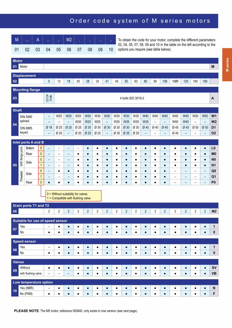
M ... A .. .. M2 . . .. .. To obtain the code for your motor, complete the different parameters 02, 04, 05, 07, 08, 09 and 10 in the table on the left according to the options you require (see table below).01 02 03 04 05 06 07 08 09 10
Motor01 Motor M
Displacement02 5 12 18 25 28 32 41 45 50 63 80 90 108 108R 125 160 180
Mounting flange
03
ceTo
p2 t
bolts
4 bolts ISo 3019-2 A
Shaft
04
DIN 5480 splined
– W25 W25 W25 W30 W30 W30 W30 W30 W30 W40 W40 W40 W45 W45 W50 W50 W1– – – W30 W25 W25 – W35 W35 W35 W35 – – W40 W40 – – W2
DIN 6885 keyed
Ø 18 Ø 25 Ø 25 Ø 25 Ø 30 Ø 30 Ø 30 Ø 30 Ø 30 Ø 30 Ø 40 Ø 40 Ø 40 Ø 45 Ø 45 Ø 50 Ø 50 D1– Ø 20 – Ø 30 Ø 25 Ø 25 – Ø 35 Ø 35 Ø 35 – – – Ø 40 – – – D2
Inlet ports A and B
05 SAE
flang
e por
ts Bottom 0 – – – – ● ● ● ● ● ● ● ● ● ● ● ● ● L0Rear 0 – – – ● ● ● ● ● ● ● ● ● ● ● ● ● ● M0
Side0 – – – ● ● ● ● ● ● ● ● ● ● ● ● ● ● N01 – – – ● ● ● ● ● ● ● ● ● ● ● ● ● ● N1
Threa
ded Side
0 – ● ● ● ● ● ● ● ● ● ● ● ● – – – – Q01 – – – ● ● ● ● ● ● ● ● ● ● – – – – Q1
Rear 0 ● ● ● ● ● ● ● ● ● ● ● ● ● – – – – P0
Drain ports T1 and T206 2 2 2 2 2 2 2 2 2 2 2 2 2 2 2 2 2 M2
Suitable for use of speed sensor
07Yes – ● ● ● ● ● ● ● ● ● ● ● ● ● ● ● ● 1No ● ● ● ● ● ● ● ● ● ● ● ● ● ● ● ● ● 0
Speed sensor
08Yes – ● ● ● ● ● ● ● ● ● ● ● ● ● ● ● ● 1No ● ● ● ● ● ● ● ● ● ● ● ● ● ● ● ● ● 0
Valves
09Without ● ● ● ● ● ● ● ● ● ● ● ● ● ● ● ● ● SVwith flushing valve – – – ● ● ● ● ● ● ● ● ● ● ● ● ● ● VB
Low temperature option
10Yes (NBR) – ● ● ● ● ● ● ● ● ● ● ● ● ● ● ● ● NNo (FKM) ● ● ● ● ● ● ● ● ● ● ● ● ● ● ● ● ● F
0 = Without suitability for valves 1 = Compatible with flushing valve
PLeASe Note: The M5 motor, reference 093840, only exists in one version (see next page).
O r d e r c o d e s y s t e m o f M s e r i e s m o t o r s
M s e r i e s m o t o r s
M6x
1
40 −
00.50
12
20.5
Ø 18
+0.00
8-0
.003
Ø
25
49 +−
10.5
P 6
Ø 80
0 - 0.04
6
45.50
25°
8 9
150
79.1
T2 : G 1/4"
T1 : G1/4" 100
Ø 11
6 Ø 127 MAXI
R53
96 M
AXI
P 150
66.5
39.1
53
36
139
77
G ½"
38
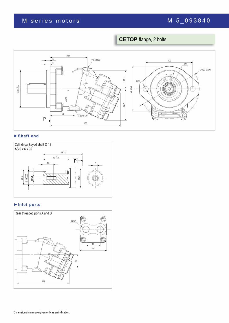
Rear threaded ports A and B
►Inlet ports
M 5 _ 0 9 3 8 4 0
Dimensions in mm are given only as an indication.
CetoP flange, 2 bolts
cylindrical keyed shaft Ø 18AS 6 x 6 x 32
►Shaft end
M s
erie
s
51.5
92.3
155
34.2
13 T3 : M8x1
12
18.2
40°
81.3
Ø 100
45° 45°
70.7
95
Ø 9
95
Ø 16
47.5
39.2
T2 : M12x1.5
Ø 80
20 +10
0 − 0.0
2
P
T1 : M12x1.5
70.7
6
Ø 25 M 10
x 1.5
28
Ø 30
40 8
22
0- 0.5
60 + 1− 0.5
P
+ 0.0
15+
0.002
M6x
1
40 −
00.50
16
Ø 20
+ 0.0
15+
0.002
Ø 30
60 +− 10.5
P 6
22.5
M 10
x 1.5
28
Ø 30
22
480
- 0.5
+ 1− 0.5
P
88
58 87
123.4
M 22 x 1.5
34
M 22 x 1.5
143.3
8775
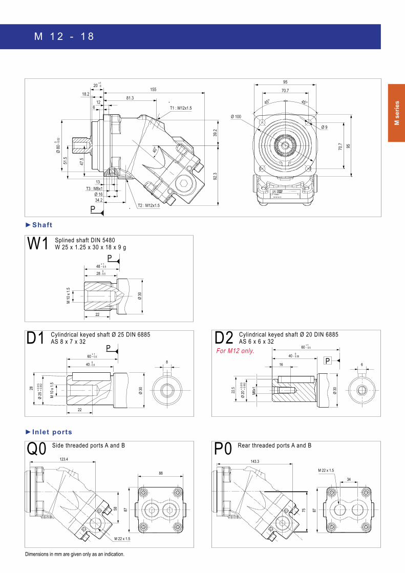
For M12 only.D1 cylindrical keyed shaft Ø 25 DIN 6885
AS 8 x 7 x 32 D2 cylindrical keyed shaft Ø 20 DIN 6885 AS 6 x 6 x 32
W1 Splined shaft DIN 5480 W 25 x 1.25 x 30 x 18 x 9 g
Q0 Side threaded ports A and B p0 Rear threaded ports A and B
►Shaft
►Inlet ports
Dimensions in mm are given only as an indication.
M 1 2 - 1 8

M s e r i e s m o t o r s
8
56
40°
108
69
15 T3 : M10x1
107.70
42.2
Ø 11
88.4
118
Ø 125
Ø 17
T1 : M16x1.5
T2 : M16x1.5
Ø 10
0
+1025
0 − 0.0
2
P
59
88.4
118
M 8 x
1.25
28
50
19
Ø 35
Ø 25
0- 0.5
+ 0.0
15+
0.002
8
75 + 1− 0.5
P
8
75 + 1− 0.5
P
50 0- 0.5
Ø 35
M 10
x 1.5
33
Ø 30
+ 0.0
15+
0.002
22
19
28
43
M 8 x
1.25
Ø 35
0- 0.5
68 + 1− 0.5
P
35
Ø 35
0- 0.5
60 + 1− 0.5
P
22
M10
x 1.5
27
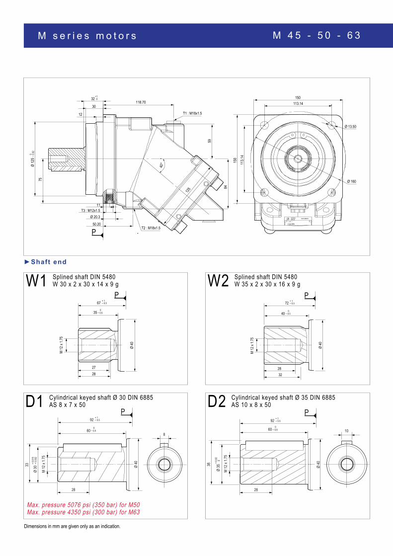
D1 cylindrical keyed shaft Ø 25 DIN 6885 AS 8 x 7 x 40 D2 cylindrical keyed shaft Ø 30 DIN 6885
AS 8 x 7 x 40
►Shaft end
W1 Splined shaft DIN 5480 W 25 x 1.25 x 30 x 18 x 9 g W2 Splined shaft DIN 5480
W 30 x 2 x 30 x 14 x 9 g
Dimensions in mm are given only as an indication.
M 2 5

M s
erie
s
179.2
107.2
78.9
159.4
58
M27x2 depth 16
179.2
107.2
65.1
142.9
120
M27x2 depth 16
144.1179
66.1
107.2
40.5
12018.2
Ø 11M 8 depth 15
M 8 depth 15
18.2
40.5
59
70
107.2
149
Ø 11
179
p0 Rear threaded ports A and B
N0orN1 Side flange ports A and B SAE 1/2″ 6000 psi
Q0 Side threaded ports
M0 Rear flange ports A and B SAE 1/2″ 6000 psi
►Inlet ports
Dimensions in mm are given only as an indication.
M 2 5
M27x2depth 16
144.6
179.3
66.6
107.2
120 Q1 Side threaded ports

M s e r i e s m o t o r s
W2 Splined shaft DIN 5480 W 25 x 1.25 x 30 x 18 x 9 g
8
56
40°
69
15 T3 : M10x1
107.70
118
88.4
108
59
Ø 17
T1 : M16x1.5
T2 : M16x1.5 42.20
118
Ø 125
Ø 11
25+10
Ø 10
00
− 0.0
2
P
88.4
M 10
x 1.5
Ø 35
22
27
35 − 0.50
60 + 1− 0.5
P
19
43
28
M 8 x
1.25
Ø 35
− 0.50
68 + 1− 0.5
P
M 10
x1.5
33
22
50
Ø 35
Ø 30
− 0.50
+ 0.0
02+
0.015
8
75 + 1− 0.5
P
M 8 x
1.25
28
50
19
Ø 35
Ø 25
0- 0.5
+ 0.0
15+
0.002
8
75 + 1− 0.5
P
Not available on M 41.
►Shaft end
W1 Splined shaft DIN 5480 W 30 x 2 x 30 x 14 x 9 g
D1cylindrical keyed shaft Ø 30 DIN 6885 AS 8 x 7 x 40 D2 cylindrical keyed shaft Ø 25 DIN 6885
AS 8 x 7 x 40
Dimensions in mm are given only as an indication.
Not available on M 41.
M 2 8 - 3 2 - 4 1

M s
erie
s
Ø 11
18.2
75.4
155.2185
112
40.5
59
M8 depth 15drilling depth 18
Ø 1188
.3
155
40.5
59
M8 depth 15
115
18.240
112
185
40.5
120
18.2
M8 depth 15drilling depth 18
150.2
71.2
185
112
Ø 11
120
M27x2 depth 16
149
70.3
112.3
185.3
58
M27x2 depth 16
185.3
112.3
84
165.6 185.5
150.8
112.3
71.7
M27x2 depth 16
4.72 (120)
L0 SAe flange ports, bottom SAE 1/2″ 6000 psi M0 Rear flange ports
SAE 1/2″ 6000 psi
N0orN1 Side flange ports A and B SAE 1/2″ 6000 psi Q0 Side threaded ports A and B
p0 Rear threaded ports Q1 Side threaded ports A and B
►Inlet ports
Dimensions in mm are given only as an indication.
M 2 8 - 3 2 - 4 1
M s e r i e s m o t o r s
12
59
40°
84
11 T3 : M12x1.5
30
125
T1 : M18x1.5
T2 : M18x1.5 50.20
Ø 20.3
118.70
Ø 13.50
150
150
113.14
113.1
4
32+10
Ø 12
50
− 0.0
2
P
Ø 16075
M 12
x 1.7
5
Ø 40
2827
35 − 0.50
67 + 1− 0.5
P
M 12
x 1.7
5
2832
40Ø
40− 0.5
0
72 + 1− 0.5
P
M 12
x 1.7
5
33
Ø 30
+ 0.0
02+
0.015
60 − 0.50
28
Ø 40
8
92 + 1− 0.5
P
M 12
x 1.7
5
38
Ø 35
0+
0.02
60 − 0.50
28
Ø 40
10
92 + 1− 0.5
P
Max. pressure 5076 psi (350 bar) for M50Max. pressure 4350 psi (300 bar) for M63
W1 Splined shaft DIN 5480 W 30 x 2 x 30 x 14 x 9 g W2 Splined shaft DIN 5480
W 35 x 2 x 30 x 16 x 9 g
D1 cylindrical keyed shaft Ø 30 DIN 6885 AS 8 x 7 x 50 D2 cylindrical keyed shaft Ø 35 DIN 6885
AS 10 x 8 x 50
►Shaft end
Dimensions in mm are given only as an indication.
M 4 5 - 5 0 - 6 3
M s
erie
s
Ø 17
91
176202
125.9
75
M10 depth 17
50.8
23.8
Ø 17
103.3
177.7
50.8
75 147
23.849
M10 depth 17
202.5
125.9
50.8
136
23.8
M 10 depth 17
168.2
84.5
211.7
129
Ø 17
168.2
84.2
127.9
210.2
M33x2depth 18
169.2 210.6
85.3
128.2
M33x2depth 18
136
210.2
127.9
100.3
187
58
M33 x 2 depth 18
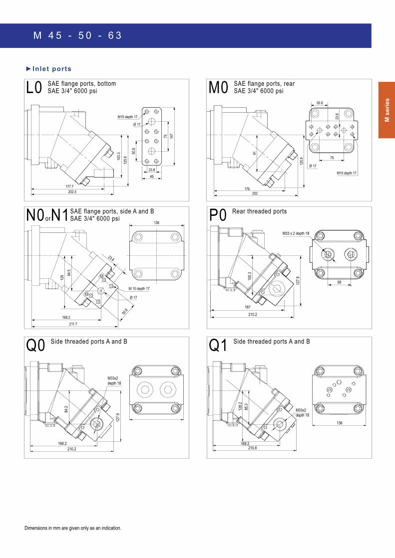
Q1 Side threaded ports A and B
L0 SAe flange ports, bottom SAE 3/4″ 6000 psi M0 SAe flange ports, rear
SAE 3/4″ 6000 psi
N0orN1 SAE flange ports, side A and B SAE 3/4″ 6000 psi
Q0 Side threaded ports A and B
p0 Rear threaded ports
►Inlet ports
Dimensions in mm are given only as an indication.
M 4 5 - 5 0 - 6 3

M s e r i e s m o t o r s
29
20
133 90
.50
68
63.20
10
T3 : M12x1.5 14
82.50
T1 : M18x1.5
122.7
T2 : M18x1.5
Ø 13.50
127.3
16
5
Ø 14
0
32+10
0−
0.02
P
40°
Ø 23
165
127.3
Ø 180
M 16
x 2
36
45
37
Ø 45
− 0.50
77 + 1− 0.5
P
M 12
x 1.7
5
25
40
32
Ø 45
− 0.50
72 + 1− 0.5
P
M16 x
2
43
Ø 40
+ 0.0
15+
0.002
70 − 0.50
36
Ø 45
12
102 + 1− 0.5
P
W2 Splined shaft DIN 5480 W 35 x 2 x 30 x 16 x 9 g
W1 Splined shaft DIN 5480 W 40 x 2 x 30 x 18 x 9 g D1 cylindrical keyed shaft Ø 40 DIN 6885
AS 12 x 8 x 56
►Shaft end
For M 80 only.
Dimensions in mm are given only as an indication.
M 8 0 - 9 0 - 1 0 8
M s
erie
s
84
27.8
57.2
Ø 23
M12 depth 20
99.2
136.3
197.5
225.7
M 12 x 175depth 20
194.4
27.8
57.2
245
96.6
148.1
160
Ø 23
57.2
84 166
27.862.5
M12 depth 20
116
200
Ø 23
230.2
136.3
F
E
AB
D
C
147.4
96
.6
243.8 194.4
M33x2 depth 18
160
AB
C
D
E
F
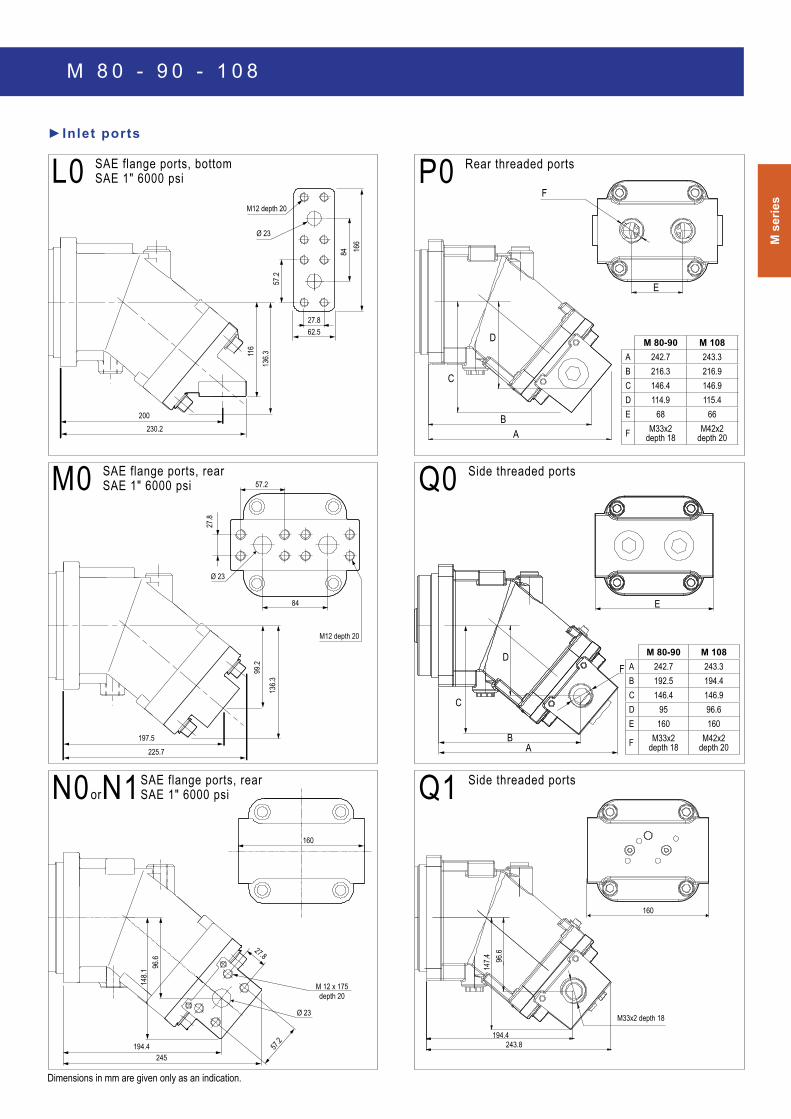
Q1 Side threaded ports
M 80-90 M 108A 242.7 243.3B 216.3 216.9c 146.4 146.9D 114.9 115.4e 68 66
F M33x2 depth 18
M42x2 depth 20
M 80-90 M 108A 242.7 243.3B 192.5 194.4c 146.4 146.9D 95 96.6e 160 160
F M33x2 depth 18
M42x2 depth 20
M0 SAe flange ports, rear SAE 1″ 6000 psi
N0orN1 SAE flange ports, rear SAE 1″ 6000 psi
L0 SAe flange ports, bottom SAE 1″ 6000 psi
►Inlet ports
Q0 Side threaded ports
p0 Rear threaded ports
Dimensions in mm are given only as an indication.
M 8 0 - 9 0 - 1 0 8

M s e r i e s m o t o r sM
16 x
2
36
50
40
Ø 55
− 0.50
90 + 1− 0.5
P
M 12
x 1.7
5
28
45
36
Ø 55
− 0.50
85 + 1− 0.5
P
M16 x
2
48.5
Ø 45
+ 0.0
18+
0.002
80 − 0.50
36
Ø 55
120 + 1− 0.5
P
14
M12 x
1.75
43
Ø 40
+ 0.0
18+
0.002
80 − 0.50
28
Ø 55
120 + 1− 0.5
P
12
W1 Splined shaft DIN 5480 W 45 x 2 x 30 x 21 x 9 g
W2 Splined shaft DIN 5480 W 40 x 2 x 30 x 18 x 9 g
D1 cylindrical keyed shaft Ø 45 DIN 6885 AS 14 x 9 x 63
D2 cylindrical keyed shaft Ø 40 DIN 6885 AS 12 x 8 x 56
►Shaft end
Dimensions in mm are given only as an indication.
190
190
141.4
141.4
40°
164
87.50
Ø160
0 - 0
.025
36.50
40 + 10
23
10
107.5
22.50
98
T 3 : M14x1.5
59.9
152.1
T2 : M18x1.5
T1 : M18x1.5
Ø 17.50
Ø 200
P 65
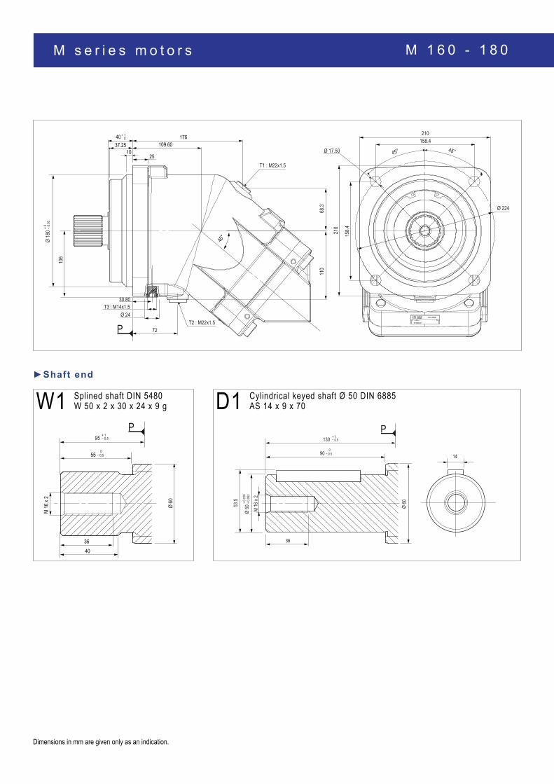
Max. pressure 5076 (350 bar) for M 125. For M 108 R only.
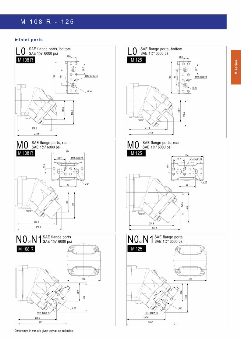
M 1 0 8 R - 1 2 5
M s
erie
s
159.9
265.3
66.7
31.8
Ø 31
M14 depth 19
100.8
207.6
178
261.5
156.9
120.2
230.8
194
99
66.7
31.8
M14 depth 19
Ø 31
211.8
119.7
148.2
245.8
198
66.7
31.8
M14 depth 19 99
Ø 30
209.5
117.8
146.3
243.5
198
66.7
31.8
Ø 30
M14 depth 1999
259.2
155
228.2
118
194
99
66.7
31.8
M14 depth 19
Ø 31
M0 SAe flange ports, rear SAE 1¼″ 6000 psi M0 SAe flange ports, rear
SAE 1¼″ 6000 psi
N0orN1 SAE flange ports SAE 1¼″ 6000 psi
L0 SAe flange ports, bottom SAE 1¼″ 6000 psi
►Inlet ports
M 125
M 108 R M 125
Dimensions in mm are given only as an indication.
L0 SAe flange ports, bottom SAE 1¼″ 6000 psi
M 108 R
158
263
66.7
31.8
M14 depth 19
98.9
205.3
178
Ø 31
N0orN1 SAE flange ports SAE 1¼″ 6000 psi
M 108 R
M 1 0 8 R - 1 2 5
M 125
M s e r i e s m o t o r s
110
1037.25
25
176109.60
40 + 10
Ø
180 +
0 − 0.0
3
30.80 T3 : M14x1.5
Ø 24 T2 : M22x1.5
72
68.3
210
T1 : M22x1.5
210158.4
45° 45°
Ø 224
P
40°
106
158.4
Ø 17.50
M 16
x 2
36
55
40
Ø 60
− 0.50
95 + 1− 0.5
P
M 16
x 2
53.5
Ø 50
+ 0.0
18+
0.002
90 − 0.50
36
Ø 60
130 + 1− 0.5
P
14
W1 Splined shaft DIN 5480 W 50 x 2 x 30 x 24 x 9 g D1 cylindrical keyed shaft Ø 50 DIN 6885
AS 14 x 9 x 70
►Shaft end
Dimensions in mm are given only as an indication.
M 1 6 0 - 1 8 0

M s
erie
s
99
66.70
31.80Ø 32
M14 depth 19
199
146.1 17
0
249290
M14 depth 19
107.7
170
66.70
31.80
295238
Ø 32
200
253
290
120
170
Ø 32
M14 depth 19
31.8
66.70
19499
M0 SAe flange ports, rear SAE 1¼″ 6000 psi N0orN1 SAE flange ports
SAE 1¼″ 6000 psi
L0 SAe flange ports, bottom SAE 1¼″ 6000 psi
►Inlet ports
Dimensions in mm are given only as an indication.
M 1 6 0 - 1 8 0