Embed Size (px)
Citation preview
Report ITU-R M.2039-3 (11/2014)
Characteristics of terrestrial IMT-2000 systems for frequency sharing/
interference analyses
M Series
Mobile, radiodetermination, amateur
and related satellite services
ii Rep. ITU-R M.2039-3
Foreword
The role of the Radiocommunication Sector is to ensure the rational, equitable, efficient and economical use of the
radio-frequency spectrum by all radiocommunication services, including satellite services, and carry out studies without
limit of frequency range on the basis of which Recommendations are adopted.
The regulatory and policy functions of the Radiocommunication Sector are performed by World and Regional
Radiocommunication Conferences and Radiocommunication Assemblies supported by Study Groups.
Policy on Intellectual Property Right (IPR)
ITU-R policy on IPR is described in the Common Patent Policy for ITU-T/ITU-R/ISO/IEC referenced in Annex 1 of
Resolution ITU-R 1. Forms to be used for the submission of patent statements and licensing declarations by patent
holders are available from http://www.itu.int/ITU-R/go/patents/en where the Guidelines for Implementation of the
Common Patent Policy for ITU-T/ITU-R/ISO/IEC and the ITU-R patent information database can also be found.
Series of ITU-R Reports
(Also available online at http://www.itu.int/publ/R-REP/en)
Series Title
BO Satellite delivery
BR Recording for production, archival and play-out; film for television
BS Broadcasting service (sound)
BT Broadcasting service (television)
F Fixed service
M Mobile, radiodetermination, amateur and related satellite services
P Radiowave propagation
RA Radio astronomy
RS Remote sensing systems
S Fixed-satellite service
SA Space applications and meteorology
SF Frequency sharing and coordination between fixed-satellite and fixed service systems
SM Spectrum management
Note: This ITU-R Report was approved in English by the Study Group under the procedure detailed in
Resolution ITU-R 1.
Electronic Publication
Geneva, 2015
ITU 2015
All rights reserved. No part of this publication may be reproduced, by any means whatsoever, without written permission of ITU.
Rep. ITU-R M.2039-3 1
REPORT ITU-R M.2039-3
Characteristics of terrestrial IMT-2000 systems for frequency
sharing/interference analyses
(2004-2009-2010-2014)
TABLE OF CONTENTS
Page
1 Introduction .................................................................................................................... 2
2 Acronyms and definitions ............................................................................................... 3
3 IMT-2000 interfaces ....................................................................................................... 5
4 Non-deployment related parameters ............................................................................... 6
4.1 Non-deployment related parameters for IMT-2000 CDMA DS (interface
No. 1) .................................................................................................................. 7
4.2 Non-deployment related parameters for IMT-2000 CDMA MC (CDMA
2000, HRPD and UMB) (interface No. 2) .......................................................... 13
4.3 Non-deployment related parameters for IMT-2000 CDMA TDD (interface
No. 3) .................................................................................................................. 17
4.4 Non-deployment related parameters for IMT-2000 TDMA SC (interface No.
4) ......................................................................................................................... 24
4.5 Non-deployment related parameters for IMT-2000 FDMA/TDMA (interface
No. 5) .................................................................................................................. 26
4.6 Non-deployment related parameters for IMT-2000 OFDMA TDD WMAN
(interface No. 6) .................................................................................................. 27
5 Deployment-related parameters in the bands below 1 GHz ........................................... 31
5.1 Deployment-related parameters for IMT-2000 CDMA DS (interface No. 1) .... 31
5.2 Deployment-related parameters for IMT-2000 CDMA MC (CDMA 2000,
HRPD and UMB) (interface No. 2) .................................................................... 34
5.3 Deployment-related parameters for IMT-2000 CDMA TDD (interface No.
3) ......................................................................................................................... 39
5.4 Deployment-related parameters for IMT-2000 OFDMA TDD WMAN
(interface No. 6) .................................................................................................. 41
5.5 Spectrum emission mask for terminal/mobile station equipment operating in
the band 3 400-3 600 MHz ................................................................................. 43
References ................................................................................................................................ 45
2 Rep. ITU-R M.2039-3
1 Introduction
International Mobile Telecommunications 2000 (IMT-2000) third generation mobile systems
started service around the year 2000, and provide access by means of one or more radio links to a
wide range of telecommunications services supported by the fixed telecommunication networks
(e.g. PSTN/ISDN/ Internet protocol (IP)) and to other services specific to mobile users. Since then,
IMT-2000 has been continually enhanced.
The Radiocommunication Assembly 2007 adopted Resolution ITU-R 56 that resolves that the term
“IMT” be the root name that encompasses both IMT-2000 and IMT-Advanced collectively.
Certain bands are identified for IMT in the Radio Regulations (RR) and the frequency arrangements
used in those bands can be found in Recommendation ITU-R M.1036.
Frequency sharing studies and interference analyses involving IMT systems and other systems and
services operating in bands identified for IMT may need to be undertaken within ITU R.
To perform the necessary sharing studies between IMT systems and systems in other services,
characteristics of the terrestrial component of IMT systems are needed.
This Report provides the baseline characteristics of terrestrial IMT-2000 systems only for use in
frequency sharing and interference analysis studies involving IMT-2000 systems and between
IMT-2000 systems and other systems.
Recommendations ITU-R M.1457, ITU-R M.1580 and ITU-R M.1581 provide standardization
information relating to IMT-2000 interfaces.
Parameters for IMT-Advanced interfaces are not addressed in this Report. They are addressed in
Report ITU-R M.2292.
The characteristics of the IMT-2000 interfaces have been grouped by frequency ranges:
– below 1 GHz,
– between 1 and 3 GHz,
– between 3 and 6 GHz.
Band specific variations, if any, are reflected in the tables.
2 Acronyms and definitions
3GPP 3rd Generation Partnership Project
3GPP2 3rd Generation Partnership Project 2
ACLR Adjacent channel leakage ratio
ACR Adjacent channel rejection
ACS Adjacent channel selectivity
BS Base station
BW Bandwidth
CDMA Code-division multiple access
DECT Digital enhanced cordless telecommunications
DL Downlink
EDGE Enhanced data rates for GSM evolution
Rep. ITU-R M.2039-3 3
e.i.r.p. Equivalent isotropic radiated power
e.r.p. Effective radiated power
E-UTRA Evolved UTRA
EV-DO Evolution-Data Optimized
EV-DV Evolution-Data/Voice
FDD Frequency division duplex
FDMA Frequency-division multiple access
GMSK Gaussian minimum shift keying
HPSK Hybrid phase shift keying
HRPD High rate packet data
HSPA High speed packet access
HSPA+ Evolved high speed packet access
IMT International Mobile Telecommunications – root name that encompasses both
IMT 2000 and IMT-Advanced collectively
IMT-2000 International Mobile Telecommunications 2000
IMT-Advanced International Mobile Telecommunications-Advanced – previously known as
systems beyond IMT 2000
I/N Interference to noise ratio
LTE Long term evolution
MC Multi-carrier
MS Mobile station
N/A Not applicable
OFDMA Orthogonal frequency-division multiple access
PUSC Partially used sub-channel
QAM Quadrature amplitude modulation
QPSK Quadrature phase shift keying
RF Radio frequency
SC-FDMA Single carrier frequency division multiple access
SDO Standards development organization
TDD Time division duplex
TDMA Time-division multiple access
TD-SCDMA Time division synchronous code-division multiple access
TR Technical report of 3GPP
TS Technical specification of 3GPP
4 Rep. ITU-R M.2039-3
TX Transmitter
UE User equipment
UL Uplink
UMB Ultra mobile broadband
UMTS Universal mobile telecommunication system
UT User terminal
UTRA Universal terrestrial radio access
UWC Universal wireless communications
WCDMA Wideband code-division multiple access
WiMAX Worldwide interoperability for microwave access
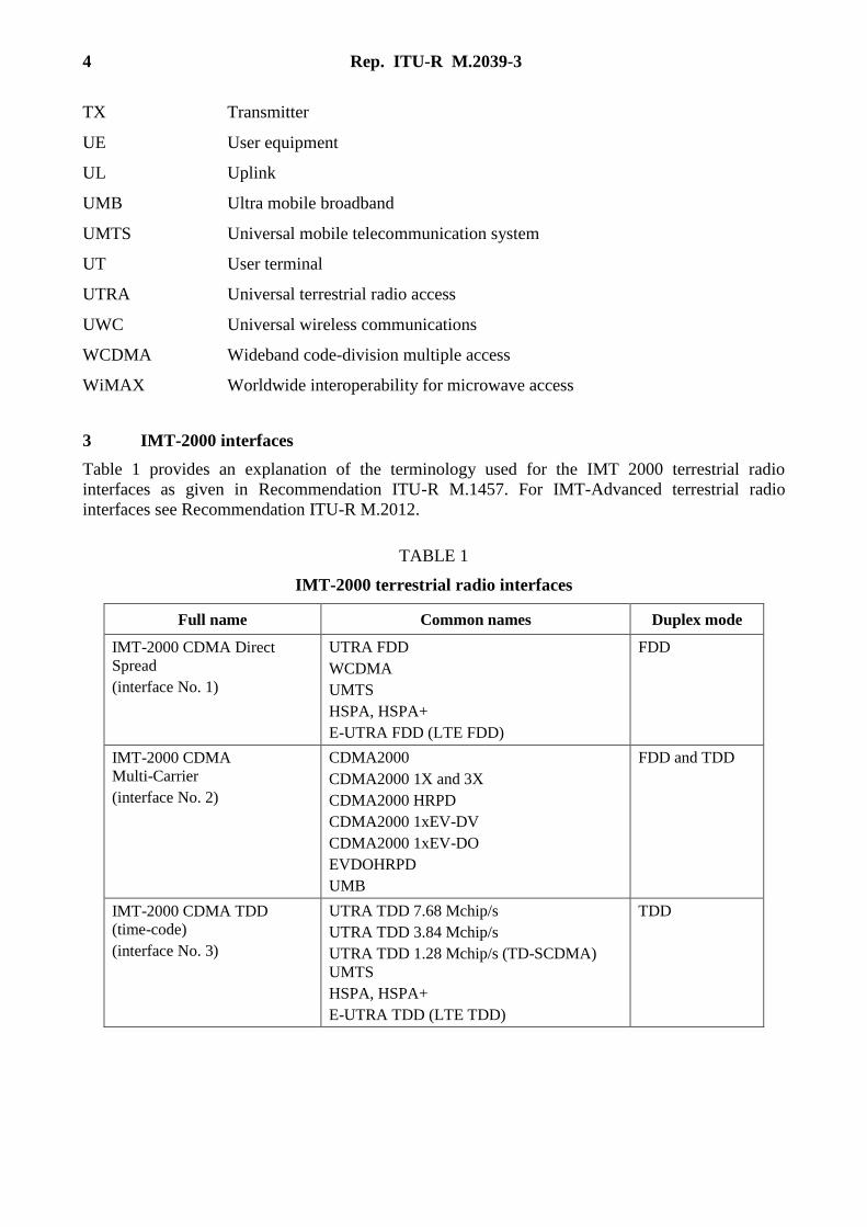
3 IMT-2000 interfaces
Table 1 provides an explanation of the terminology used for the IMT 2000 terrestrial radio
interfaces as given in Recommendation ITU-R M.1457. For IMT-Advanced terrestrial radio
interfaces see Recommendation ITU-R M.2012.
TABLE 1
IMT-2000 terrestrial radio interfaces
Full name Common names Duplex mode
IMT-2000 CDMA Direct
Spread
(interface No. 1)
UTRA FDD
WCDMA
UMTS
HSPA, HSPA+
E-UTRA FDD (LTE FDD)
FDD
IMT-2000 CDMA
Multi-Carrier
(interface No. 2)
CDMA2000
CDMA2000 1X and 3X
CDMA2000 HRPD
CDMA2000 1xEV-DV
CDMA2000 1xEV-DO
EVDOHRPD
UMB
FDD and TDD
IMT-2000 CDMA TDD
(time-code)
(interface No. 3)
UTRA TDD 7.68 Mchip/s
UTRA TDD 3.84 Mchip/s
UTRA TDD 1.28 Mchip/s (TD-SCDMA)
UMTS
HSPA, HSPA+
E-UTRA TDD (LTE TDD)
TDD
Rep. ITU-R M.2039-3 5
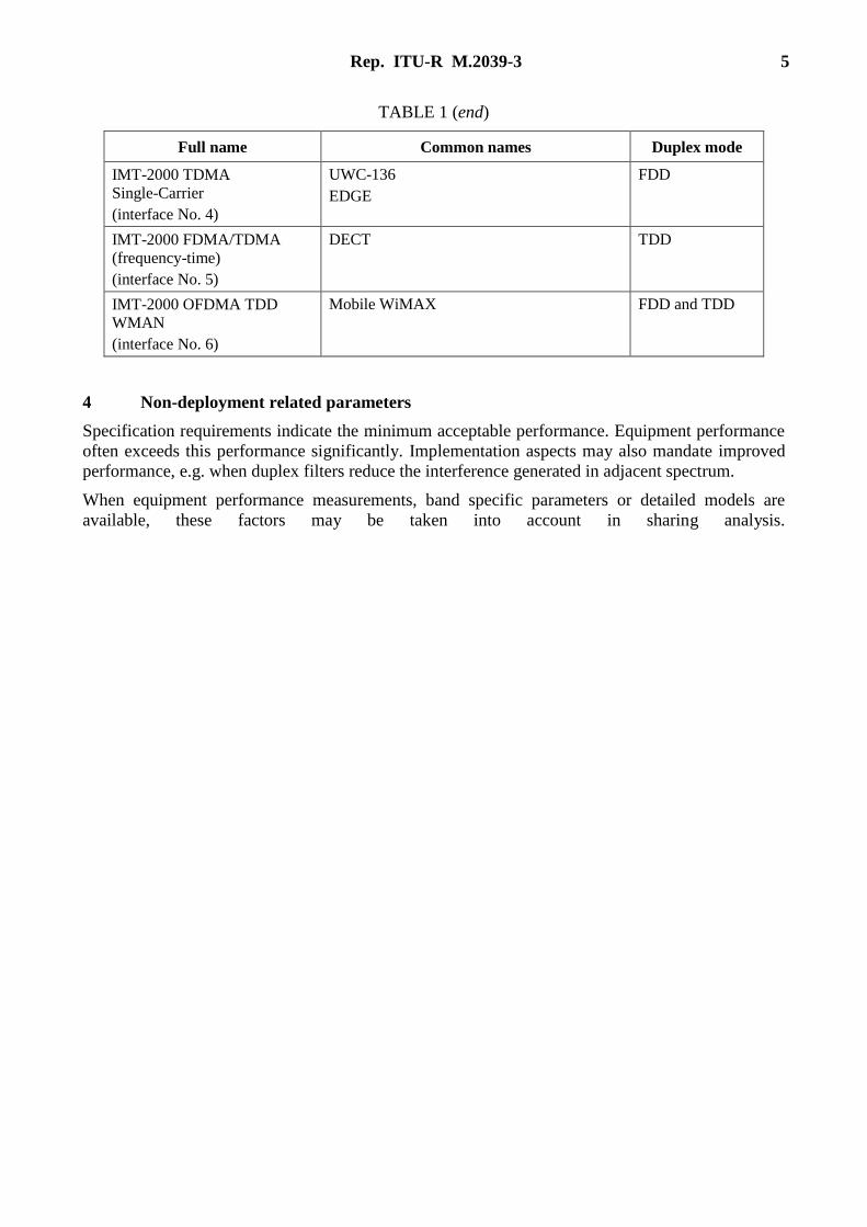
TABLE 1 (end)
Full name Common names Duplex mode
IMT-2000 TDMA
Single-Carrier
(interface No. 4)
UWC-136
EDGE
FDD
IMT-2000 FDMA/TDMA
(frequency-time)
(interface No. 5)
DECT TDD
IMT-2000 OFDMA TDD
WMAN
(interface No. 6)
Mobile WiMAX FDD and TDD
4 Non-deployment related parameters
Specification requirements indicate the minimum acceptable performance. Equipment performance
often exceeds this performance significantly. Implementation aspects may also mandate improved
performance, e.g. when duplex filters reduce the interference generated in adjacent spectrum.
When equipment performance measurements, band specific parameters or detailed models are
available, these factors may be taken into account in sharing analysis.
6 Rep. ITU-R M.2039-3
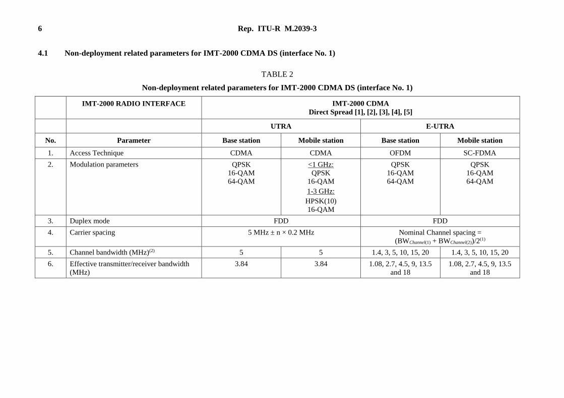
4.1 Non-deployment related parameters for IMT-2000 CDMA DS (interface No. 1)
TABLE 2
Non-deployment related parameters for IMT-2000 CDMA DS (interface No. 1)
IMT-2000 RADIO INTERFACE IMT-2000 CDMA
Direct Spread [1], [2], [3], [4], [5]
UTRA E-UTRA
No. Parameter Base station Mobile station Base station Mobile station
1. Access Technique CDMA CDMA OFDM SC-FDMA
2. Modulation parameters QPSK
16-QAM
64-QAM
<1 GHz:
QPSK
16-QAM
1-3 GHz:
HPSK(10)
16-QAM
QPSK
16-QAM
64-QAM
QPSK
16-QAM
64-QAM
3. Duplex mode FDD FDD
4. Carrier spacing 5 MHz ± n × 0.2 MHz Nominal Channel spacing =
(BWChannel(1) + BWChannel(2))/2(1)
5. Channel bandwidth (MHz)(2) 5 5 1.4, 3, 5, 10, 15, 20 1.4, 3, 5, 10, 15, 20
6. Effective transmitter/receiver bandwidth
(MHz)
3.84 3.84 1.08, 2.7, 4.5, 9, 13.5
and 18
1.08, 2.7, 4.5, 9, 13.5
and 18
Rep. ITU-R M.2039-3 7
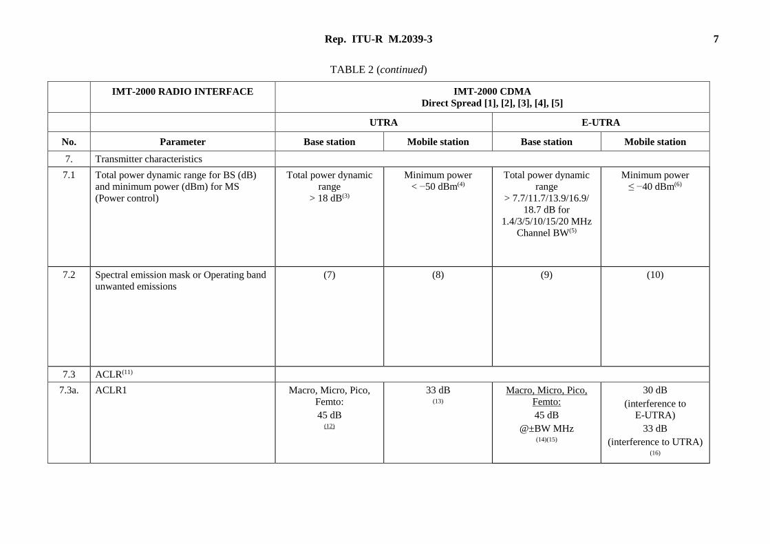
TABLE 2 (continued)
IMT-2000 RADIO INTERFACE IMT-2000 CDMA
Direct Spread [1], [2], [3], [4], [5]
UTRA E-UTRA
No. Parameter Base station Mobile station Base station Mobile station
7. Transmitter characteristics
7.1 Total power dynamic range for BS (dB)
and minimum power (dBm) for MS
(Power control)
Total power dynamic
range
> 18 dB(3)
Minimum power
< −50 dBm(4)
Total power dynamic
range
> 7.7/11.7/13.9/16.9/
18.7 dB for
1.4/3/5/10/15/20 MHz
Channel BW(5)
Minimum power
≤ −40 dBm(6)
7.2 Spectral emission mask or Operating band
unwanted emissions
(7) (8) (9) (10)
7.3 ACLR(11)
7.3a. ACLR1 Macro, Micro, Pico,
Femto:
45 dB (12)
33 dB (13)
Macro, Micro, Pico,
Femto:
45 dB
@±BW MHz (14)(15)
30 dB
(interference to
E-UTRA)
33 dB
(interference to UTRA) (16)
8 Rep. ITU-R M.2039-3
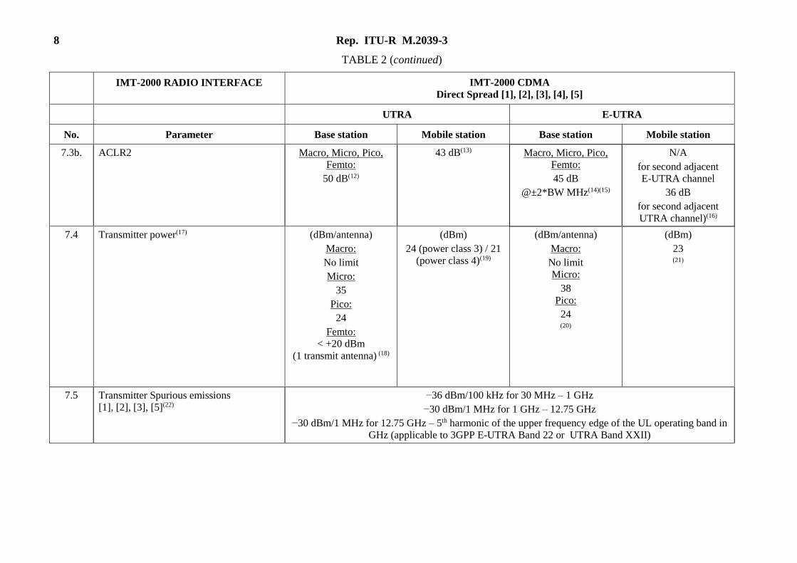
TABLE 2 (continued)
IMT-2000 RADIO INTERFACE IMT-2000 CDMA
Direct Spread [1], [2], [3], [4], [5]
UTRA E-UTRA
No. Parameter Base station Mobile station Base station Mobile station
7.3b. ACLR2 Macro, Micro, Pico,
Femto:
50 dB(12)
43 dB(13) Macro, Micro, Pico,
Femto:
45 dB
@±2*BW MHz(14)(15)
N/A
for second adjacent
E-UTRA channel
36 dB
for second adjacent
UTRA channel)(16)
7.4 Transmitter power(17) (dBm/antenna)
Macro:
No limit
Micro:
35
Pico:
24
Femto:
< +20 dBm
(1 transmit antenna) (18)
(dBm)
24 (power class 3) / 21
(power class 4)(19)
(dBm/antenna)
Macro:
No limit
Micro:
38
Pico:
24 (20)
(dBm)
23 (21)
7.5 Transmitter Spurious emissions
[1], [2], [3], [5](22)
−36 dBm/100 kHz for 30 MHz – 1 GHz
−30 dBm/1 MHz for 1 GHz – 12.75 GHz
−30 dBm/1 MHz for 12.75 GHz – 5th harmonic of the upper frequency edge of the UL operating band in
GHz (applicable to 3GPP E-UTRA Band 22 or UTRA Band XXII)
Rep. ITU-R M.2039-3 9
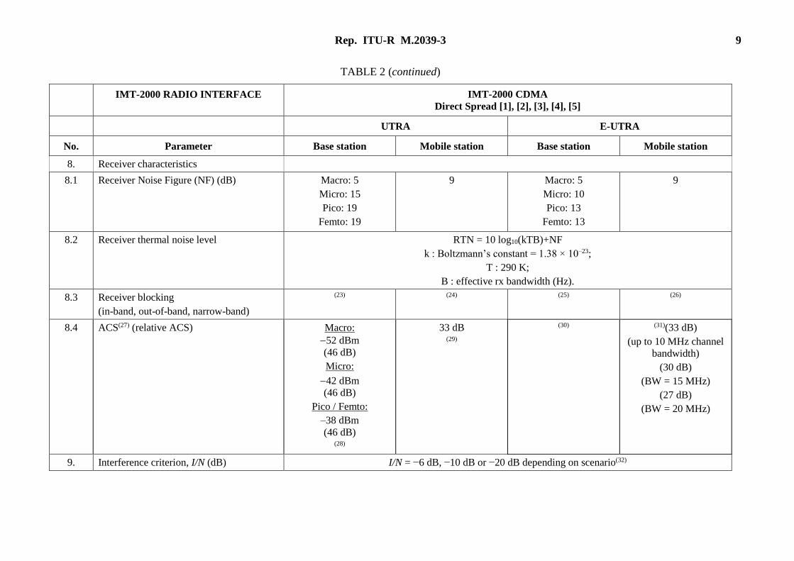
TABLE 2 (continued)
IMT-2000 RADIO INTERFACE IMT-2000 CDMA
Direct Spread [1], [2], [3], [4], [5]
UTRA E-UTRA
No. Parameter Base station Mobile station Base station Mobile station
8. Receiver characteristics
8.1 Receiver Noise Figure (NF) (dB) Macro: 5
Micro: 15
Pico: 19
Femto: 19
9 Macro: 5
Micro: 10
Pico: 13
Femto: 13
9
8.2 Receiver thermal noise level RTN = 10 log10(kTB)+NF
k : Boltzmann’s constant = 1.38 × 10⁻²³;
T : 290 K;
B : effective rx bandwidth (Hz).
8.3 Receiver blocking
(in-band, out-of-band, narrow-band)
(23) (24) (25) (26)
8.4 ACS(27) (relative ACS) Macro:
52 dBm
(46 dB)
Micro:
42 dBm
(46 dB)
Pico / Femto:
–38 dBm
(46 dB) (28)
33 dB (29)
(30) (31)(33 dB)
(up to 10 MHz channel
bandwidth)
(30 dB)
(BW = 15 MHz)
(27 dB)
(BW = 20 MHz)
9. Interference criterion, I/N (dB) I/N = −6 dB, −10 dB or −20 dB depending on scenario(32)
10 Rep. ITU-R M.2039-3
Notes relative to Table 2: (1) BWChannel(1) and BWChannel(2) are the channel bandwidths of the two respective E-UTRA carriers. Supported channel bandwidths: 1.4 MHz, 3 MHz, 5 MHz,
10 MHz, 15 MHz and 20 MHz. (2) This value refers to the transmission bandwidth. (3) See 3GPP Document: TS 25 104, § 6.4 (4) See 3GPP Document: TS 25 101, § 6.4 (5) See 3GPP Document: TS 36 104, § 6.3 (6) See 3GPP Document: TS 36 101, § 6.3 (7) See 3GPP Documents: TS 25 104, § 6.6.2.1 or TS 37 104, § 6.6.2 (8) See 3GPP Documents: TS 25 101, § 6.6.2.1 (9) See 3GPP Documents: TS 36 104, § 6.6.3 or TS 37 104 § 6.6.2 (10) See 3GPP Documents: TS 36 101, § 6.6.2 (11) These unwanted emission limits are the upper limits from SDO specifications for laboratory testing with maximum transmitting power. It is assumed that
when the in-band transmitting power is reduced by x dB through power control, the unwanted emission levels would be reduced by x dB in consequence in
the coexistence simulations. (12) See 3GPP Documents: TS 25 104, § 6.6.2.2 or TS 37 104, § 6.6.4 (13) See 3GPP Documents: TS 25 101, § 6.6.2.2 (14) ACLR applies up to 10 MHz outside the operating band. Stricter limits may apply beyond 10 MHz outside the operating band, see 3GPP Documents
TS 36 104 § 6.6.2 or TS 37 104 § 6.6.4
(15) BW represents the channel bandwidth. Supported channel bandwidths: 1.4 MHz, 3 MHz, 5 MHz, 10 MHz, 15 MHz and 20 MHz. (16) See 3GPP Document TS 36.101, § 6.6.2.3. The ACLR value provided in the table applies to a single-UE occupying the whole channel bandwidth. (17) Transmit power values refer to maximum values defined in the specifications. For actual powers to be used in sharing studies see the deployment specific
parameters. (18) See 3GPP Documents: TS 25 104, § 6.2 or TS 37 104, § 6.2.
(19) See 3GPP Document TS 25.101, § 6.2. (20) See 3GPP Documents: TS 36 104, § 6.2 or TS 37 104, § 6.2. (21) See 3GPP Document TS 36.101, § 6.2. (22) 3GPP specifies additional spurious emissions for co-existence/co-location between 3GPP technologies.
Rep. ITU-R M.2039-3 11
Notes relative to Table 2 (end): (23) See 3GPP Document TS 25.104, § 7.5 or TS 37 104 § 7.4, § 7.5 (24) See 3GPP Document TS 25.101, § 7.6 (25) See 3GPP Document TS 36.104, §§ 7.5, 7.6 or TS 37 104 §§ 7.4, 7.5 (26) See 3GPP Document TS 36.101, § 7.6 (27) The absolute ACS values are the test values as specified in 3GPP TS 25.104 § 7.4. The following conversion formula:
ACS_relative = ACS_test – Noise_floor – 10 log10 (10M/10 – 1)
can be used to derive relative ACS values, where M is the margin (dB) used in the ACS test, which is the useful signal level above the reference sensitivity
level. For both IMT 2000 CDMA direct spread and IMT 2000 CDMA TDD (time code), E.g. M = 6 dB for Macro BS. ACS relative values are often used
in sharing studies. For values of M see 3GPP Documents: TS 25.104 § 7.4, TS 36.104 § 7.5 or TS 37.104 § 7.4. (28) See 3GPP Document TS 25.104, § 7.4 (29) See 3GPP Document TS 25.101, § 7.5 (30) E-UTRA BS receiver ACS and blocking test conditions are specified in 3GPP 36.104 § 7.5, those test conditions should be used to derive E-UTRA BS
receiver mask with the conversion formula in note (27), special care is needed when deriving the E-UTRA BS receiver mask for channel bandwidth larger
than 5 MHz since a 5 MHz interfering signal is specified in the ACS and Blocking test conditions. (31) E-UTRA UE ACS values are to be used if the E-UTRA victim channel bandwidth is the same as interferer transmitting channel bandwidth. In case that the
E-UTRA victim channel bandwidth is different from the interferer transmitting channel bandwidth, the E-UTRA receiver mask needs to be derived with
the formula in note (27) using the E-UTRA UE ACS and Blocking test conditions defined in 3GPP TS 36.101 § 7.5, special care is needed when deriving
the E-UTRA UE receiver mask for UE channel bandwidth larger than 5 MHz since a 5 MHz interfering signal is specified in the ACS and Blocking test
conditions. (32) Different protection criteria correspond to different interference situations: I/N = −6 dB (corresponding to 1 dB reduction of the receiver sensitivity) is
applicable to cases where interference affects one or a few cells, or when the IMT-2000 system is interference limited. In other cases I/N = −10 dB
(corresponding to 0.4 dB reduction of the receiver sensitivity) is applicable. In case of interference from systems which are allowed to be operated on lower
priority basis, including in particular license exempt systems, a requirement of I/N = −20 dB applies. In case of multiple interfering services, the allowed
interference should be partitioned among the interferers. These criteria may be modified in case of cross-border negotiations.
12 Rep. ITU-R M.2039-3
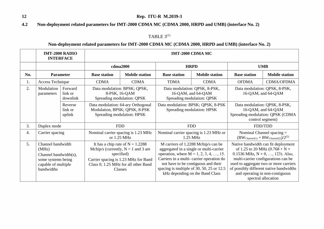
4.2 Non-deployment related parameters for IMT-2000 CDMA MC (CDMA 2000, HRPD and UMB) (interface No. 2)
TABLE 3(1)
Non-deployment related parameters for IMT-2000 CDMA MC (CDMA 2000, HRPD and UMB) (interface No. 2)
IMT-2000 RADIO
INTERFACE
IMT-2000 CDMA MC
cdma2000 HRPD UMB
No. Parameter Base station Mobile station Base station Mobile station Base station Mobile station
1. Access Technique CDMA CDMA TDMA CDMA OFDMA CDMA/OFDMA
2. Modulation
parameters
Forward
link or
downlink
Data modulation: BPSK; QPSK,
8-PSK, 16-QAM
Spreading modulation: QPSK
Data modulation: QPSK, 8-PSK,
16-QAM, and 64-QAM
Spreading modulation: QPSK
Data modulation: QPSK, 8-PSK,
16-QAM, and 64-QAM
Reverse
link or
uplink
Data modulation: 64-ary Orthogonal
Modulation, BPSK; QPSK, 8-PSK
Spreading modulation: HPSK
Data modulation: BPSK; QPSK, 8-PSK
Spreading modulation: HPSK
Data modulation: QPSK, 8-PSK,
16-QAM, and 64-QAM
Spreading modulation: QPSK (CDMA
control segment)
3. Duplex mode FDD FDD FDD/TDD
4. Carrier spacing Nominal carrier spacing is 1.23 MHz
or 1.25 MHz
Nominal carrier spacing is 1.23 MHz or
1.25 MHz
Nominal Channel spacing =
(BWChannel(1) + BWChannel(2))/2(2)
5. Channel bandwidth
(MHz)
Channel bandwidth(s),
some systems being
capable of multiple
bandwidths
It has a chip rate of N = 1.2288
Mchip/s (currently, N = 1 and 3 are
specified)
Carrier spacing is 1.23 MHz for Band
Class 0; 1.25 MHz for all other Band
Classes
M carriers of 1.2288 Mchip/s can be
aggregated in a single or multi-carrier
operation, where M = 1, 2, 3, 4, …, 15.
Carriers in a multi- carrier operation do
not have to be contiguous and their
spacing is multiple of 30, 50, 25 or 12.5
kHz depending on the Band Class
Native bandwidth can fit deployment
of 1.25 to 20 MHz (0.768 + N ×
0.1536 MHz, N × 0, …, 123). Also,
multi-carrier configurations can be
used to aggregate two or more carriers
of possibly different native bandwidths
and operating in non-contiguous
spectral allocation
Rep. ITU-R M.2039-3 13
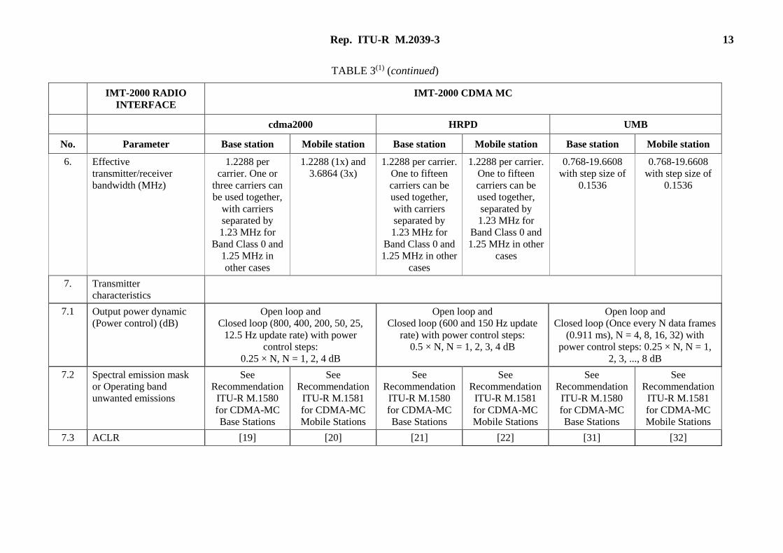
TABLE 3(1) (continued)
IMT-2000 RADIO
INTERFACE
IMT-2000 CDMA MC
cdma2000 HRPD UMB
No. Parameter Base station Mobile station Base station Mobile station Base station Mobile station
6. Effective
transmitter/receiver
bandwidth (MHz)
1.2288 per
carrier. One or
three carriers can
be used together,
with carriers
separated by
1.23 MHz for
Band Class 0 and
1.25 MHz in
other cases
1.2288 (1x) and
3.6864 (3x)
1.2288 per carrier.
One to fifteen
carriers can be
used together,
with carriers
separated by
1.23 MHz for
Band Class 0 and
1.25 MHz in other
cases
1.2288 per carrier.
One to fifteen
carriers can be
used together,
separated by
1.23 MHz for
Band Class 0 and
1.25 MHz in other
cases
0.768-19.6608
with step size of
0.1536
0.768-19.6608
with step size of
0.1536
7. Transmitter
characteristics
7.1 Output power dynamic
(Power control) (dB)
Open loop and
Closed loop (800, 400, 200, 50, 25,
12.5 Hz update rate) with power
control steps:
0.25 × N, N = 1, 2, 4 dB
Open loop and
Closed loop (600 and 150 Hz update
rate) with power control steps:
0.5 × N, N = 1, 2, 3, 4 dB
Open loop and
Closed loop (Once every N data frames
(0.911 ms), N = 4, 8, 16, 32) with
power control steps: 0.25 × N, N = 1,
2, 3, ..., 8 dB
7.2 Spectral emission mask
or Operating band
unwanted emissions
See
Recommendation
ITU-R M.1580
for CDMA-MC
Base Stations
See
Recommendation
ITU-R M.1581
for CDMA-MC
Mobile Stations
See
Recommendation
ITU-R M.1580
for CDMA-MC
Base Stations
See
Recommendation
ITU-R M.1581
for CDMA-MC
Mobile Stations
See
Recommendation
ITU-R M.1580
for CDMA-MC
Base Stations
See
Recommendation
ITU-R M.1581
for CDMA-MC
Mobile Stations
7.3 ACLR [19] [20] [21] [22] [31] [32]
14 Rep. ITU-R M.2039-3
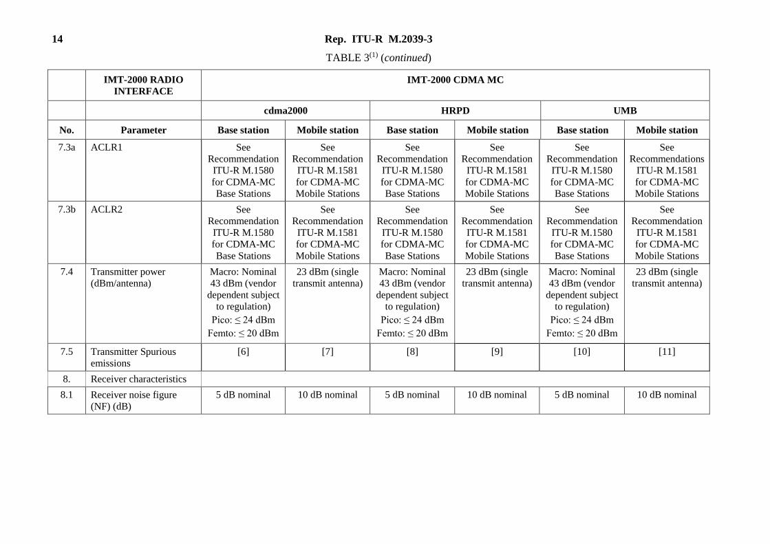
TABLE 3(1) (continued)
IMT-2000 RADIO
INTERFACE
IMT-2000 CDMA MC
cdma2000 HRPD UMB
No. Parameter Base station Mobile station Base station Mobile station Base station Mobile station
7.3a ACLR1 See
Recommendation
ITU-R M.1580
for CDMA-MC
Base Stations
See
Recommendation
ITU-R M.1581
for CDMA-MC
Mobile Stations
See
Recommendation
ITU-R M.1580
for CDMA-MC
Base Stations
See
Recommendation
ITU-R M.1581
for CDMA-MC
Mobile Stations
See
Recommendation
ITU-R M.1580
for CDMA-MC
Base Stations
See
Recommendations
ITU-R M.1581
for CDMA-MC
Mobile Stations
7.3b ACLR2 See
Recommendation
ITU-R M.1580
for CDMA-MC
Base Stations
See
Recommendation
ITU-R M.1581
for CDMA-MC
Mobile Stations
See
Recommendation
ITU-R M.1580
for CDMA-MC
Base Stations
See
Recommendation
ITU-R M.1581
for CDMA-MC
Mobile Stations
See
Recommendation
ITU-R M.1580
for CDMA-MC
Base Stations
See
Recommendation
ITU-R M.1581
for CDMA-MC
Mobile Stations
7.4 Transmitter power
(dBm/antenna)
Macro: Nominal
43 dBm (vendor
dependent subject
to regulation)
Pico: ≤ 24 dBm
Femto: ≤ 20 dBm
23 dBm (single
transmit antenna)
Macro: Nominal
43 dBm (vendor
dependent subject
to regulation)
Pico: ≤ 24 dBm
Femto: ≤ 20 dBm
23 dBm (single
transmit antenna)
Macro: Nominal
43 dBm (vendor
dependent subject
to regulation)
Pico: ≤ 24 dBm
Femto: ≤ 20 dBm
23 dBm (single
transmit antenna)
7.5 Transmitter Spurious
emissions
[6] [7] [8] [9] [10] [11]
8. Receiver characteristics
8.1 Receiver noise figure
(NF) (dB)
5 dB nominal 10 dB nominal 5 dB nominal 10 dB nominal 5 dB nominal 10 dB nominal
Rep. ITU-R M.2039-3 15
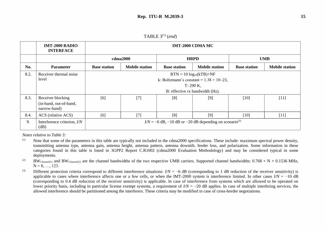
TABLE 3(1) (end)
IMT-2000 RADIO
INTERFACE
IMT-2000 CDMA MC
cdma2000 HRPD UMB
No. Parameter Base station Mobile station Base station Mobile station Base station Mobile station
8.2. Receiver thermal noise
level
RTN = 10 log10(kTB)+NF
k: Boltzmann’s constant = 1.38 × 10⁻²³,
T: 290 K,
B: effective rx bandwidth (Hz).
8.3. Receiver blocking
(in-band, out-of-band,
narrow-band)
[6] [7] [8] [9] [10] [11]
8.4. ACS (relative ACS) [6] [7] [8] [9] [10] [11]
9. Interference criterion, I/N
(dB)
I/N = −6 dB, −10 dB or −20 dB depending on scenario(3)
Notes relative to Table 3: (1) Note that some of the parameters in this table are typically not included in the cdma2000 specifications. These include: maximum spectral power density,
transmitting antenna type, antenna gain, antenna height, antenna pattern, antenna downtilt, feeder loss, and polarization. Some information in these
categories found in this table is listed in 3GPP2 Report C.R1002 (cdma2000 Evaluation Methodology) and may be considered typical in some
deployments. (2) BWChannel(1) and BWChannel(2) are the channel bandwidths of the two respective UMB carriers. Supported channel bandwidths: 0.768 + N × 0.1536 MHz,
N = 0, …, 123. (3) Different protection criteria correspond to different interference situations: I/N = −6 dB (corresponding to 1 dB reduction of the receiver sensitivity) is
applicable to cases where interference affects one or a few cells, or when the IMT-2000 system is interference limited. In other cases I/N = −10 dB
(corresponding to 0.4 dB reduction of the receiver sensitivity) is applicable. In case of interference from systems which are allowed to be operated on
lower priority basis, including in particular license exempt systems, a requirement of I/N = −20 dB applies. In case of multiple interfering services, the
allowed interference should be partitioned among the interferers. These criteria may be modified in case of cross-border negotiations.
16 Rep. ITU-R M.2039-3
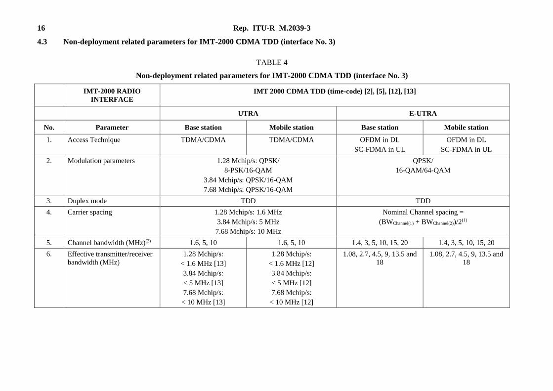
4.3 Non-deployment related parameters for IMT-2000 CDMA TDD (interface No. 3)
TABLE 4
Non-deployment related parameters for IMT-2000 CDMA TDD (interface No. 3)
IMT-2000 RADIO
INTERFACE
IMT 2000 CDMA TDD (time-code) [2], [5], [12], [13]
UTRA E-UTRA
No. Parameter Base station Mobile station Base station Mobile station
1. Access Technique TDMA/CDMA TDMA/CDMA OFDM in DL
SC-FDMA in UL
OFDM in DL
SC-FDMA in UL
2. Modulation parameters 1.28 Mchip/s: QPSK/
8-PSK/16-QAM
3.84 Mchip/s: QPSK/16-QAM
7.68 Mchip/s: QPSK/16-QAM
QPSK/
16-QAM/64-QAM
3. Duplex mode TDD TDD
4. Carrier spacing 1.28 Mchip/s: 1.6 MHz
3.84 Mchip/s: 5 MHz
7.68 Mchip/s: 10 MHz
Nominal Channel spacing =
(BWChannel(1) + BWChannel(2))/2(1)
5. Channel bandwidth (MHz)(2) 1.6, 5, 10 1.6, 5, 10 1.4, 3, 5, 10, 15, 20 1.4, 3, 5, 10, 15, 20
6. Effective transmitter/receiver
bandwidth (MHz)
1.28 Mchip/s:
< 1.6 MHz [13]
3.84 Mchip/s:
< 5 MHz [13]
7.68 Mchip/s:
< 10 MHz [13]
1.28 Mchip/s:
< 1.6 MHz [12]
3.84 Mchip/s:
< 5 MHz [12]
7.68 Mchip/s:
< 10 MHz [12]
1.08, 2.7, 4.5, 9, 13.5 and
18
1.08, 2.7, 4.5, 9, 13.5 and
18
Rep. ITU-R M.2039-3 17
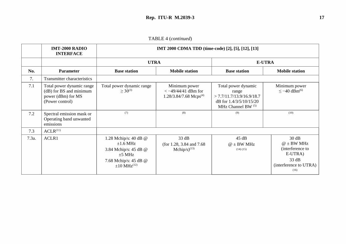
TABLE 4 (continued)
IMT-2000 RADIO
INTERFACE
IMT 2000 CDMA TDD (time-code) [2], [5], [12], [13]
UTRA E-UTRA
No. Parameter Base station Mobile station Base station Mobile station
7. Transmitter characteristics
7.1 Total power dynamic range
(dB) for BS and minimum
power (dBm) for MS
(Power control)
Total power dynamic range
≥ 30(3)
Minimum power
< −49/44/41 dBm for
1.28/3.84/7.68 Mcps(4)
Total power dynamic
range
> 7.7/11.7/13.9/16.9/18.7
dB for 1.4/3/5/10/15/20
MHz Channel BW (5)
Minimum power
≤ −40 dBm(6)
7.2 Spectral emission mask or
Operating band unwanted
emissions
(7) (8) (9) (10)
7.3 ACLR(11)
7.3a. ACLR1 1.28 Mchip/s: 40 dB @
±1.6 MHz
3.84 Mchip/s: 45 dB @
±5 MHz
7.68 Mchip/s: 45 dB @
±10 MHz(12)
33 dB
(for 1.28, 3.84 and 7.68
Mchip/s)(13)
45 dB
@ ± BW MHz (14) (15)
30 dB
@ ± BW MHz
(interference to
E-UTRA)
33 dB
(interference to UTRA) (16)
18 Rep. ITU-R M.2039-3
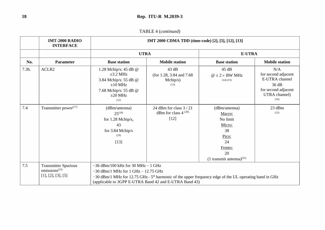
TABLE 4 (continued)
IMT-2000 RADIO
INTERFACE
IMT 2000 CDMA TDD (time-code) [2], [5], [12], [13]
UTRA E-UTRA
No. Parameter Base station Mobile station Base station Mobile station
7.3b. ACLR2 1.28 Mchip/s: 45 dB @
±3.2 MHz
3.84 Mchip/s: 55 dB @
±10 MHz
7.68 Mchip/s: 55 dB @
±20 MHz (12)
43 dB
(for 1.28, 3.84 and 7.68
Mchip/s)
(13)
45 dB
@ ± 2 BW MHz (14) (15)
N/A
for second adjacent
E-UTRA channel
36 dB
for second adjacent
UTRA channel) (16)
7.5 Transmitter Spurious
emissions(23)
[1], [2], [3], [5]
−36 dBm/100 kHz for 30 MHz – 1 GHz
−30 dBm/1 MHz for 1 GHz – 12.75 GHz
−30 dBm/1 MHz for 12.75 GHz– 5th harmonic of the upper frequency edge of the UL operating band in GHz
(applicable to 3GPP E-UTRA Band 42 and E-UTRA Band 43)
7.4 Transmitter power(17) (dBm/antenna)
25(18)
for 1.28 Mchip/s,
43
for 3.84 Mchip/s (19)
[13]
24 dBm for class 3 / 21
dBm for class 4 (20)
[12]
(dBm/antenna)
Macro:
No limit
Micro:
38
Pico:
24
Femto:
20
(1 transmit antenna)(21)
23 dBm (22)
Rep. ITU-R M.2039-3 19
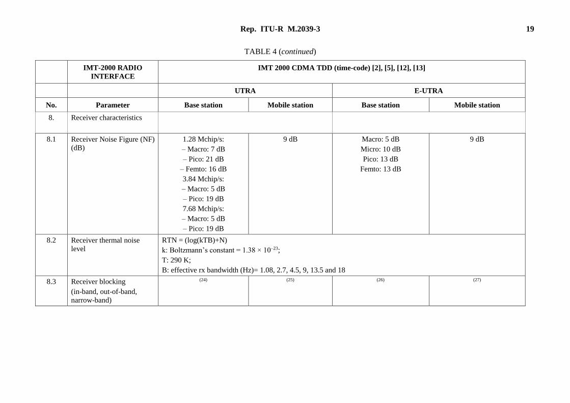
TABLE 4 (continued)
IMT-2000 RADIO
INTERFACE
IMT 2000 CDMA TDD (time-code) [2], [5], [12], [13]
UTRA E-UTRA
No. Parameter Base station Mobile station Base station Mobile station
8. Receiver characteristics
8.1 Receiver Noise Figure (NF)
(dB)
1.28 Mchip/s:
– Macro: 7 dB
– Pico: 21 dB
– Femto: 16 dB
3.84 Mchip/s:
– Macro: 5 dB
– Pico: 19 dB
7.68 Mchip/s:
– Macro: 5 dB
– Pico: 19 dB
9 dB Macro: 5 dB
Micro: 10 dB
Pico: 13 dB
Femto: 13 dB
9 dB
8.2 Receiver thermal noise
level
RTN = (log(kTB)+N)
k: Boltzmann’s constant = 1.38 × 10⁻²³;
T: 290 K;
B: effective rx bandwidth (Hz)= 1.08, 2.7, 4.5, 9, 13.5 and 18
8.3 Receiver blocking
(in-band, out-of-band,
narrow-band)
(24) (25) (26) (27)
20 Rep. ITU-R M.2039-3
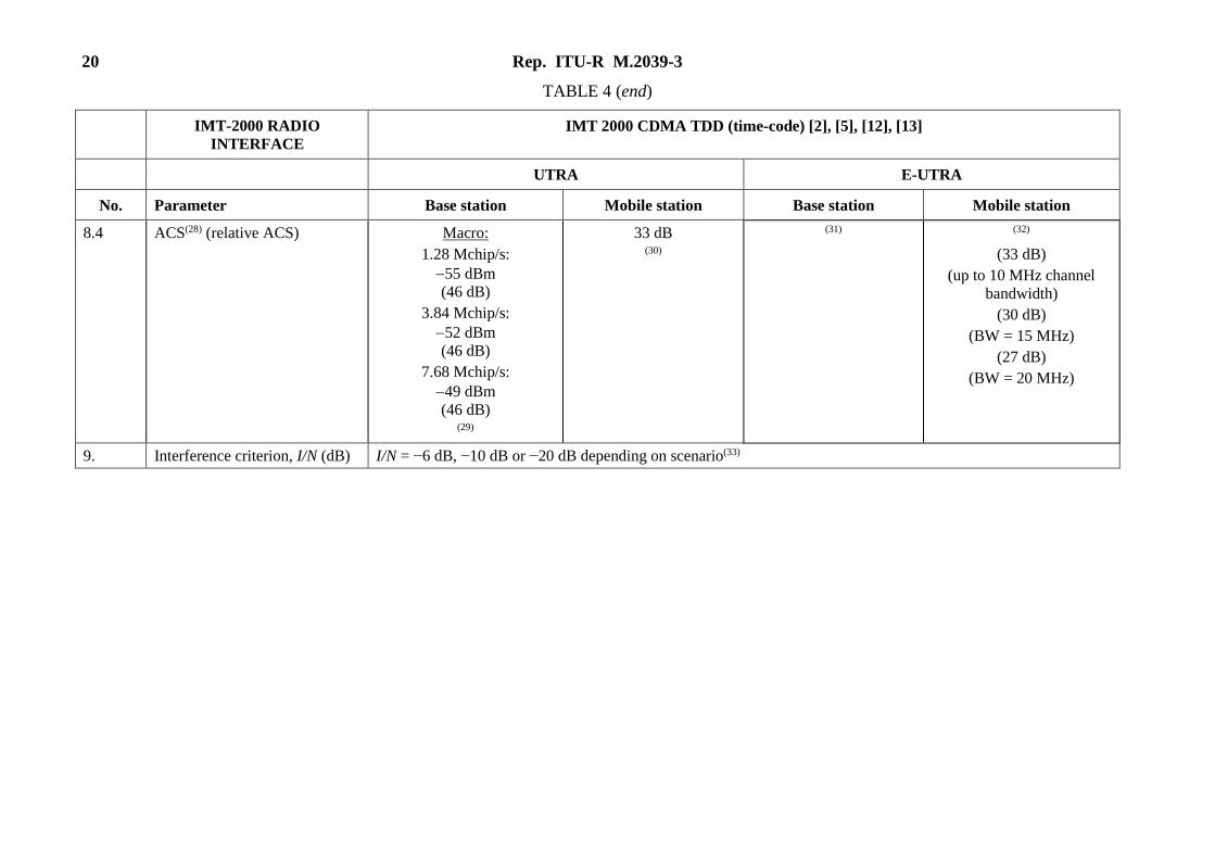
TABLE 4 (end)
IMT-2000 RADIO
INTERFACE
IMT 2000 CDMA TDD (time-code) [2], [5], [12], [13]
UTRA E-UTRA
No. Parameter Base station Mobile station Base station Mobile station
8.4 ACS(28) (relative ACS) Macro:
1.28 Mchip/s:
55 dBm
(46 dB)
3.84 Mchip/s:
52 dBm
(46 dB)
7.68 Mchip/s:
49 dBm
(46 dB)
(29)
33 dB (30)
(31) (32)
(33 dB)
(up to 10 MHz channel
bandwidth)
(30 dB)
(BW = 15 MHz)
(27 dB)
(BW = 20 MHz)
9. Interference criterion, I/N (dB) I/N = −6 dB, −10 dB or −20 dB depending on scenario(33)
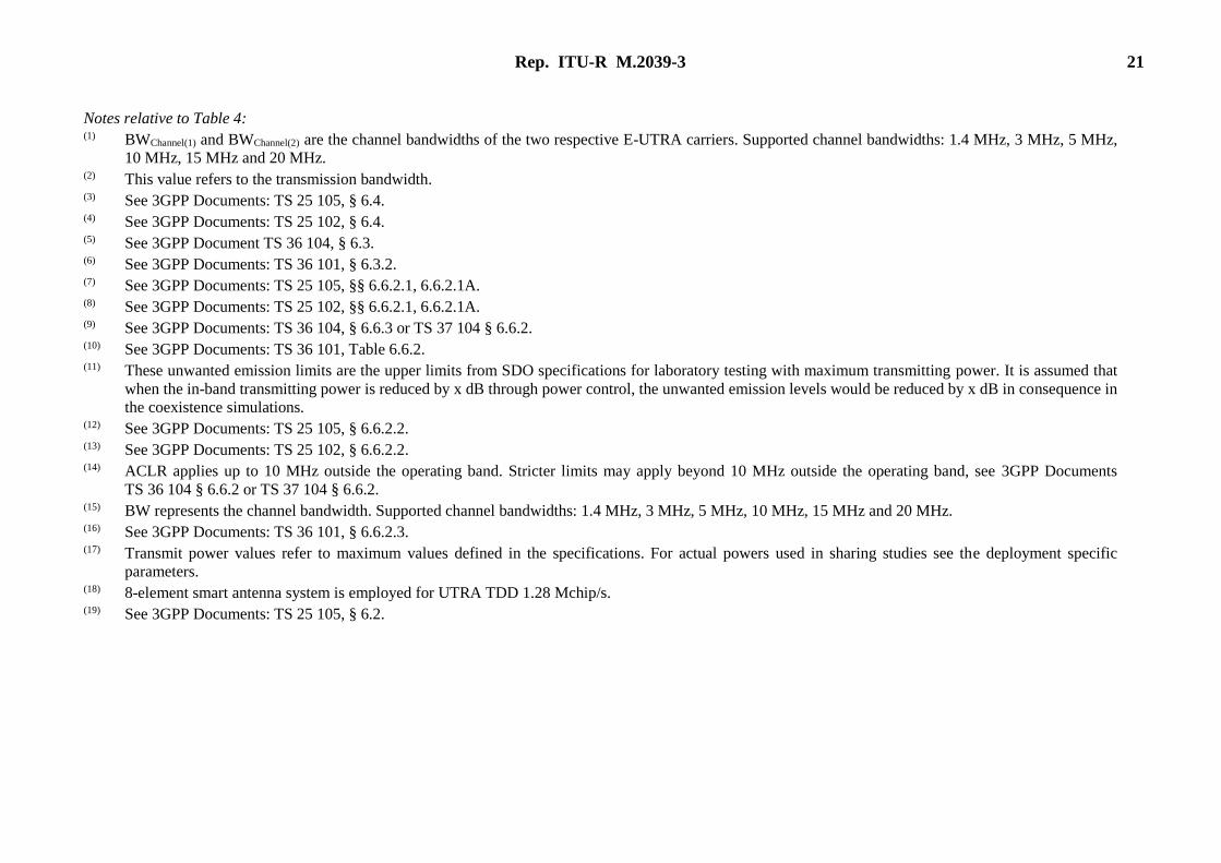
Rep. ITU-R M.2039-3 21
Notes relative to Table 4: (1) BWChannel(1) and BWChannel(2) are the channel bandwidths of the two respective E-UTRA carriers. Supported channel bandwidths: 1.4 MHz, 3 MHz, 5 MHz,
10 MHz, 15 MHz and 20 MHz. (2) This value refers to the transmission bandwidth. (3) See 3GPP Documents: TS 25 105, § 6.4. (4) See 3GPP Documents: TS 25 102, § 6.4. (5) See 3GPP Document TS 36 104, § 6.3. (6) See 3GPP Documents: TS 36 101, § 6.3.2. (7) See 3GPP Documents: TS 25 105, §§ 6.6.2.1, 6.6.2.1A. (8) See 3GPP Documents: TS 25 102, §§ 6.6.2.1, 6.6.2.1A. (9) See 3GPP Documents: TS 36 104, § 6.6.3 or TS 37 104 § 6.6.2. (10) See 3GPP Documents: TS 36 101, Table 6.6.2. (11) These unwanted emission limits are the upper limits from SDO specifications for laboratory testing with maximum transmitting power. It is assumed that
when the in-band transmitting power is reduced by x dB through power control, the unwanted emission levels would be reduced by x dB in consequence in
the coexistence simulations. (12) See 3GPP Documents: TS 25 105, § 6.6.2.2. (13) See 3GPP Documents: TS 25 102, § 6.6.2.2. (14) ACLR applies up to 10 MHz outside the operating band. Stricter limits may apply beyond 10 MHz outside the operating band, see 3GPP Documents
TS 36 104 § 6.6.2 or TS 37 104 § 6.6.2.
(15) BW represents the channel bandwidth. Supported channel bandwidths: 1.4 MHz, 3 MHz, 5 MHz, 10 MHz, 15 MHz and 20 MHz. (16) See 3GPP Documents: TS 36 101, § 6.6.2.3. (17) Transmit power values refer to maximum values defined in the specifications. For actual powers used in sharing studies see the deployment specific
parameters. (18) 8-element smart antenna system is employed for UTRA TDD 1.28 Mchip/s. (19) See 3GPP Documents: TS 25 105, § 6.2.
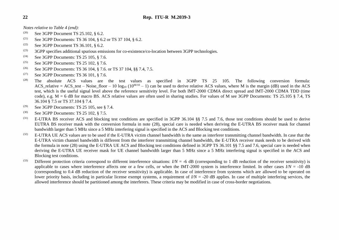
22 Rep. ITU-R M.2039-3
Notes relative to Table 4 (end): (20) See 3GPP Document TS 25.102, § 6.2. (21) See 3GPP Documents: TS 36 104, § 6.2 or TS 37 104, § 6.2. (22) See 3GPP Document TS 36.101, § 6.2. (23) 3GPP specifies additional spurious emissions for co-existence/co-location between 3GPP technologies. (24) See 3GPP Documents: TS 25 105, § 7.6. (25) See 3GPP Documents: TS 25 102, § 7.6. (26) See 3GPP Documents: TS 36 104, § 7.6. or TS 37 104, §§ 7.4, 7.5. (27) See 3GPP Documents: TS 36 101, § 7.6. (28) The absolute ACS values are the test values as specified in 3GPP TS 25 105. The following conversion formula:
ACS_relative = ACS_test – Noise_floor – 10 log10 (10M/10 – 1) can be used to derive relative ACS values, where M is the margin (dB) used in the ACS
test, which is the useful signal level above the reference sensitivity level. For both IMT-2000 CDMA direct spread and IMT-2000 CDMA TDD (time
code), e.g. M = 6 dB for macro BS. ACS relative values are often used in sharing studies. For values of M see 3GPP Documents: TS 25.105 § 7.4, TS
36.104 § 7.5 or TS 37.104 § 7.4. (29) See 3GPP Documents: TS 25 105, see § 7.4. (30) See 3GPP Documents: TS 25 102, § 7.5. (31) E-UTRA BS receiver ACS and blocking test conditions are specified in 3GPP 36.104 §§ 7.5 and 7.6, those test conditions should be used to derive
EUTRA BS receiver mask with the conversion formula in note (28), special care is needed when deriving the E-UTRA BS receiver mask for channel
bandwidth larger than 5 MHz since a 5 MHz interfering signal is specified in the ACS and Blocking test conditions. (32) E-UTRA UE ACS values are to be used if the E-UTRA victim channel bandwidth is the same as interferer transmitting channel bandwidth. In case that the
E-UTRA victim channel bandwidth is different from the interferer transmitting channel bandwidth, the E-UTRA receiver mask needs to be derived with
the formula in note (28) using the E-UTRA UE ACS and Blocking test conditions defined in 3GPP TS 36.101 §§ 7.5 and 7.6, special care is needed when
deriving the E-UTRA UE receiver mask for UE channel bandwidth larger than 5 MHz since a 5 MHz interfering signal is specified in the ACS and
Blocking test conditions. (33) Different protection criteria correspond to different interference situations: I/N = -6 dB (corresponding to 1 dB reduction of the receiver sensitivity) is
applicable to cases where interference affects one or a few cells, or when the IMT-2000 system is interference limited. In other cases I/N = -10 dB
(corresponding to 0.4 dB reduction of the receiver sensitivity) is applicable. In case of interference from systems which are allowed to be operated on
lower priority basis, including in particular license exempt systems, a requirement of I/N = -20 dB applies. In case of multiple interfering services, the
allowed interference should be partitioned among the interferers. These criteria may be modified in case of cross-border negotiations.
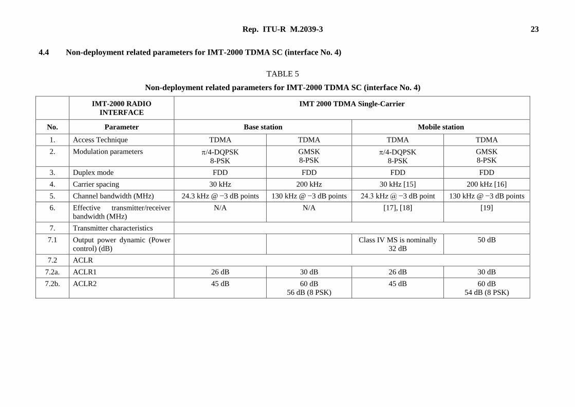
Rep. ITU-R M.2039-3 23
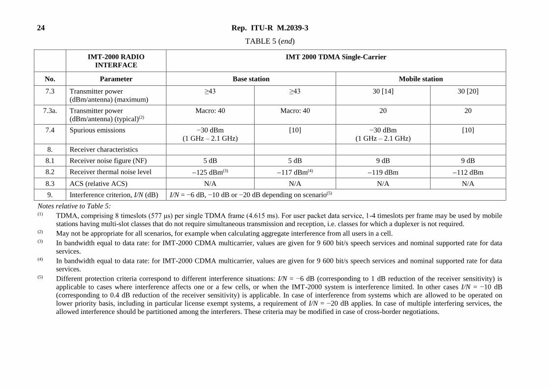
4.4 Non-deployment related parameters for IMT-2000 TDMA SC (interface No. 4)
TABLE 5
Non-deployment related parameters for IMT-2000 TDMA SC (interface No. 4)
IMT-2000 RADIO
INTERFACE
IMT 2000 TDMA Single-Carrier
No. Parameter Base station Mobile station
1. Access Technique TDMA TDMA TDMA TDMA
2. Modulation parameters /4-DQPSK
8-PSK
GMSK
8-PSK /4-DQPSK
8-PSK
GMSK
8-PSK
3. Duplex mode FDD FDD FDD FDD
4. Carrier spacing 30 kHz 200 kHz 30 kHz [15] 200 kHz [16]
5. Channel bandwidth (MHz) 24.3 kHz @ −3 dB points 130 kHz @ −3 dB points 24.3 kHz @ −3 dB point 130 kHz @ −3 dB points
6. Effective transmitter/receiver
bandwidth (MHz)
N/A N/A [17], [18] [19]
7. Transmitter characteristics
7.1 Output power dynamic (Power
control) (dB)
Class IV MS is nominally
32 dB
50 dB
7.2 ACLR
7.2a. ACLR1 26 dB 30 dB 26 dB 30 dB
7.2b. ACLR2 45 dB 60 dB
56 dB (8 PSK)
45 dB 60 dB
54 dB (8 PSK)
24 Rep. ITU-R M.2039-3
TABLE 5 (end)
IMT-2000 RADIO
INTERFACE
IMT 2000 TDMA Single-Carrier
No. Parameter Base station Mobile station
7.3 Transmitter power
(dBm/antenna) (maximum)
≥43 ≥43 30 [14] 30 [20]
7.3a. Transmitter power
(dBm/antenna) (typical)(2)
Macro: 40 Macro: 40 20 20
7.4 Spurious emissions −30 dBm
(1 GHz – 2.1 GHz)
[10] −30 dBm
(1 GHz – 2.1 GHz)
[10]
8. Receiver characteristics
8.1 Receiver noise figure (NF) 5 dB 5 dB 9 dB 9 dB
8.2 Receiver thermal noise level 125 dBm(3) 117 dBm(4) 119 dBm 112 dBm
8.3 ACS (relative ACS) N/A N/A N/A N/A
9. Interference criterion, I/N (dB) I/N = −6 dB, −10 dB or −20 dB depending on scenario(5)
Notes relative to Table 5: (1) TDMA, comprising 8 timeslots (577 μs) per single TDMA frame (4.615 ms). For user packet data service, 1-4 timeslots per frame may be used by mobile
stations having multi-slot classes that do not require simultaneous transmission and reception, i.e. classes for which a duplexer is not required. (2) May not be appropriate for all scenarios, for example when calculating aggregate interference from all users in a cell. (3) In bandwidth equal to data rate: for IMT-2000 CDMA multicarrier, values are given for 9 600 bit/s speech services and nominal supported rate for data
services. (4) In bandwidth equal to data rate: for IMT-2000 CDMA multicarrier, values are given for 9 600 bit/s speech services and nominal supported rate for data
services. (5) Different protection criteria correspond to different interference situations: I/N = −6 dB (corresponding to 1 dB reduction of the receiver sensitivity) is
applicable to cases where interference affects one or a few cells, or when the IMT-2000 system is interference limited. In other cases I/N = −10 dB
(corresponding to 0.4 dB reduction of the receiver sensitivity) is applicable. In case of interference from systems which are allowed to be operated on
lower priority basis, including in particular license exempt systems, a requirement of I/N = −20 dB applies. In case of multiple interfering services, the
allowed interference should be partitioned among the interferers. These criteria may be modified in case of cross-border negotiations.
Rep. ITU-R M.2039-3 25
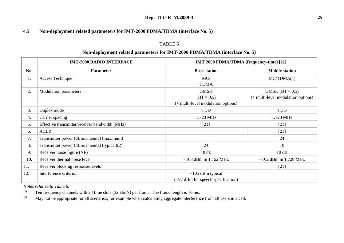
4.5 Non-deployment related parameters for IMT-2000 FDMA/TDMA (interface No. 5)
TABLE 6
Non-deployment related parameters for IMT-2000 FDMA/TDMA (interface No. 5)
IMT-2000 RADIO INTERFACE IMT 2000 FDMA/TDMA (frequency-time) [21]
No. Parameter Base station Mobile station
1. Access Technique MC/
TDMA
MC/TDMA(1)
2. Modulation parameters GMSK
(BT = 0.5)
(+ multi-level modulation options)
GMSK (BT = 0.5)
(+ multi-level modulation options)
3. Duplex mode TDD TDD
4. Carrier spacing 1.728 MHz 1.728 MHz
5. Effective transmitter/receiver bandwidth (MHz) [21] [21]
6. ACLR [21]
7. Transmitter power (dBm/antenna) (maximum) 24
8. Transmitter power (dBm/antenna) (typical)(2) 24 10
9. Receiver noise figure (NF) 10 dB 10 dB
10. Receiver thermal noise level −103 dBm in 1.152 MHz −102 dBm in 1.728 MHz
11. Receiver blocking response/levels [21]
12. Interference criterion −105 dBm typical
(−97 dBm for speech specification)
Notes relative to Table 6: (1) Ten frequency channels with 24 time slots (32 kbit/s) per frame. The frame length is 10 ms. (2) May not be appropriate for all scenarios, for example when calculating aggregate interference from all users in a cell.
26 Rep. ITU-R M.2039-3
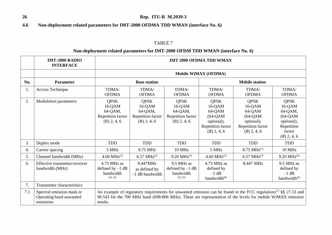
4.6 Non-deployment related parameters for IMT-2000 OFDMA TDD WMAN (interface No. 6)
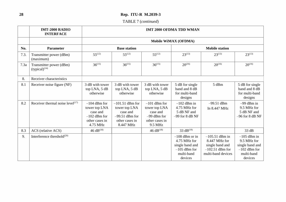
TABLE 7
Non-deployment related parameters for IMT-2000 OFDM TDD WMAN (interface No. 6)
IMT-2000 RADIO
INTERFACE
IMT 2000 OFDMA TDD WMAN
Mobile WiMAX (OFDMA)
No. Parameter Base station Mobile station
1. Access Technique TDMA/
OFDMA
TDMA/
OFDMA
TDMA/
OFDMA
TDMA/
OFDMA
TDMA/
OFDMA
TDMA/
OFDMA
2. Modulation parameters QPSK
16-QAM
64-QAM,
Repetition factor
(R) 2, 4, 6
QPSK
16-QAM
64-QAM,
Repetition factor
(R) 2, 4, 6
QPSK
16-QAM
64-QAM,
Repetition factor
(R) 2, 4, 6
QPSK
16-QAM
64-QAM
(64-QAM
optional),
Repetition factor
(R) 2, 4, 6
QPSK
16-QAM
64-QAM
(64-QAM
optional),
Repetition factor
(R) 2, 4, 6
QPSK
16-QAM
64-QAM,
(64-QAM
optional),
Repetition
factor
(R) 2, 4, 6
3. Duplex mode TDD TDD TDD TDD TDD TDD
4. Carrier spacing 5 MHz 8.75 MHz 10 MHz 5 MHz 8.75 MHz(1) 10 MHz
5. Channel bandwidth (MHz) 4.60 MHz(2) 6.57 MHz(2) 9.20 MHz(2) 4.60 MHz(2) 6.57 MHz(2) 9.20 MHz(2)
6. Effective transmitter/receiver
bandwidth (MHz)
4.75 MHz as
defined by –1 dB
bandwidth (3), (4)
8.447MHz
as defined by
–1 dB bandwidth
9.5 MHz as
defined by –1 dB
bandwidth (3), (5)
4.75 MHz as
defined by
–1 dB
bandwidth(6)
8.447 MHz 9.5 MHz as
defined by
–1 dB
bandwidth(6)
7. Transmitter characteristics
7.1 Spectral emission mask or
Operating band unwanted
emissions
An example of regulatory requirements for unwanted emission can be found in the FCC regulations(7) §§ 27.53 and
90.543 for the 700 MHz band (698-806 MHz). These are representative of the levels for mobile WiMAX emission
masks.
Rep. ITU-R M.2039-3 27
TABLE 7 (continued)
IMT-2000 RADIO
INTERFACE
IMT 2000 OFDMA TDD WMAN
Mobile WiMAX (OFDMA)
No. Parameter Base station Mobile station
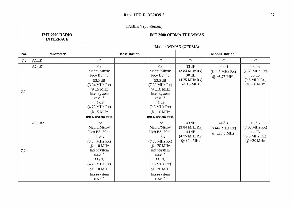
7.2 ACLR (8) (8) (9) (9) (9)
7.2a
ACLR1 For
Macro/Micro/
Pico BS: 45
53.5 dB
(3.84 MHz Rx)
@ ±5 MHz
inter-system
case(10)
45 dB
(4.75 MHz Rx)
@ ±5 MHz
Intra-system case
For
Macro/Micro/
Pico BS: 45
53.5 dB
(7.68 MHz Rx)
@ ±10 MHz
inter-system
case(10)
45 dB
(9.5 MHz Rx)
@ ±10 MHz
Intra-system case
33 dB
(3.84 MHz Rx)
30 dB
(4.75 MHz Rx)
@ ±5 MHz
30 dB
(8.447 MHz Rx)
@ ±8.75 MHz
33 dB
(7.68 MHz Rx)
30 dB
(9.5 MHz Rx)
@ ±10 MHz
7.2b
ACLR2 For
Macro/Micro/
Pico BS: 50(11)
66 dB
(3.84 MHz Rx)
@ ±10 MHz
Inter-system
case(10)
55 dB
(4.75 MHz Rx)
@ ±10 MHz
Intra-system
case(10)
For
Macro/Micro/
Pico BS: 50(11)
66 dB
(7.68 MHz Rx)
@ ±20 MHz
inter-system
case(10)
55 dB
(9.5 MHz Rx)
@ ±20 MHz
Intra-system
case(10)
43 dB
(3.84 MHz Rx)
44 dB
(4.75 MHz Rx)
@ ±10 MHz
44 dB
(8.447 MHz Rx)
@ ±17.5 MHz
43 dB
(7.68 MHz Rx)
44 dB
(9.5 MHz Rx)
@ ±20 MHz
28 Rep. ITU-R M.2039-3
TABLE 7 (continued)
IMT-2000 RADIO
INTERFACE
IMT 2000 OFDMA TDD WMAN
Mobile WiMAX (OFDMA)
No. Parameter Base station Mobile station
7.3. Transmitter power (dBm)
(maximum)
55(12) 55(12) 55(12) 23(13) 23(13) 23(13)
7.3a Transmitter power (dBm)
(typical)(14)
36(15) 36(15) 36(15) 20(16) 20(16) 20(16)
8. Receiver characteristics
8.1 Receiver noise figure (NF) 3 dB with tower
top LNA, 5 dB
otherwise
3 dB with tower
top LNA, 5 dB
otherwise
3 dB with tower
top LNA, 5 dB
otherwise
5 dB for single
band and 8 dB
for multi-band
designs
5 dBm 5 dB for single
band and 8 dB
for multi-band
designs
8.2 Receiver thermal noise level(17) –104 dBm for
tower top LNA
case and
–102 dBm for
other cases in
4.75 MHz
–101.51 dBm for
tower top LNA
case and
–99.51 dBm for
other cases in
8.447 MHz
–101 dBm for
tower top LNA
case and
–99 dBm for
other cases in
9.5 MHz
–102 dBm in
4.75 MHz for
5 dB NF and
–99 for 8 dB NF
–99.51 dBm
In 8.447 MHz
–99 dBm in
9.5 MHz for
5 dB NF and
–96 for 8 dB NF
8.3 ACS (relative ACS) 46 dB(18) 46 dB(18) 33 dB(19) 33 dB
9. Interference threshold(20) –108 dBm or in
4.75 MHz for
single band and
–105 dBm for
multi-band
devices
–105.51 dBm in
8.447 MHz for
single band and
–102.51 dBm for
multi-band devices
–105 dBm in
9.5 MHz for
single band and
–102 dBm for
multi-band
devices
Rep. ITU-R M.2039-3 29
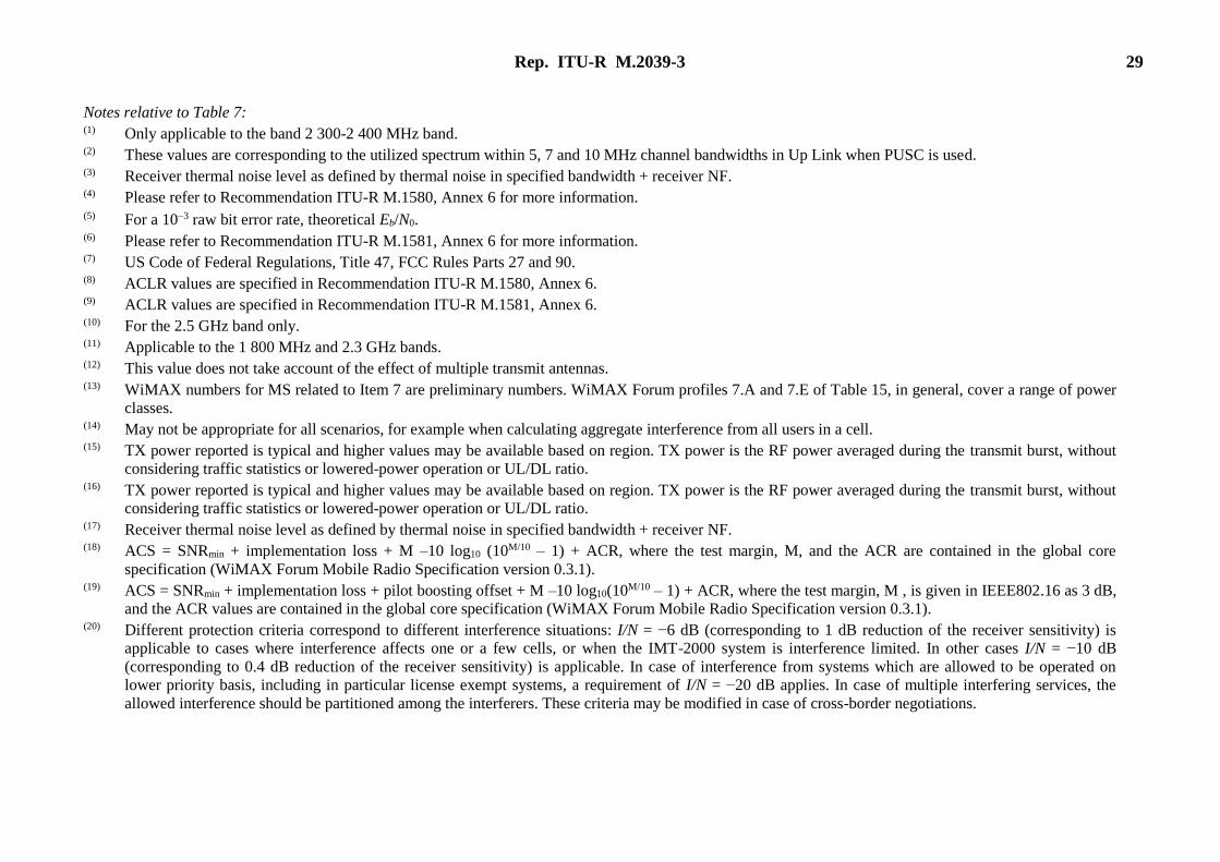
Notes relative to Table 7: (1) Only applicable to the band 2 300-2 400 MHz band. (2) These values are corresponding to the utilized spectrum within 5, 7 and 10 MHz channel bandwidths in Up Link when PUSC is used. (3) Receiver thermal noise level as defined by thermal noise in specified bandwidth + receiver NF. (4) Please refer to Recommendation ITU-R M.1580, Annex 6 for more information. (5) For a 103 raw bit error rate, theoretical Eb/N0. (6) Please refer to Recommendation ITU-R M.1581, Annex 6 for more information. (7) US Code of Federal Regulations, Title 47, FCC Rules Parts 27 and 90. (8) ACLR values are specified in Recommendation ITU-R M.1580, Annex 6. (9) ACLR values are specified in Recommendation ITU-R M.1581, Annex 6. (10) For the 2.5 GHz band only. (11) Applicable to the 1 800 MHz and 2.3 GHz bands. (12) This value does not take account of the effect of multiple transmit antennas. (13) WiMAX numbers for MS related to Item 7 are preliminary numbers. WiMAX Forum profiles 7.A and 7.E of Table 15, in general, cover a range of power
classes. (14) May not be appropriate for all scenarios, for example when calculating aggregate interference from all users in a cell. (15) TX power reported is typical and higher values may be available based on region. TX power is the RF power averaged during the transmit burst, without
considering traffic statistics or lowered-power operation or UL/DL ratio. (16) TX power reported is typical and higher values may be available based on region. TX power is the RF power averaged during the transmit burst, without
considering traffic statistics or lowered-power operation or UL/DL ratio. (17) Receiver thermal noise level as defined by thermal noise in specified bandwidth + receiver NF. (18) ACS = SNRmin + implementation loss + M –10 log10 (10M/10 – 1) + ACR, where the test margin, M, and the ACR are contained in the global core
specification (WiMAX Forum Mobile Radio Specification version 0.3.1). (19) ACS = SNRmin + implementation loss + pilot boosting offset + M –10 log10(10M/10 – 1) + ACR, where the test margin, M , is given in IEEE802.16 as 3 dB,
and the ACR values are contained in the global core specification (WiMAX Forum Mobile Radio Specification version 0.3.1). (20) Different protection criteria correspond to different interference situations: I/N = −6 dB (corresponding to 1 dB reduction of the receiver sensitivity) is
applicable to cases where interference affects one or a few cells, or when the IMT-2000 system is interference limited. In other cases I/N = −10 dB
(corresponding to 0.4 dB reduction of the receiver sensitivity) is applicable. In case of interference from systems which are allowed to be operated on
lower priority basis, including in particular license exempt systems, a requirement of I/N = −20 dB applies. In case of multiple interfering services, the
allowed interference should be partitioned among the interferers. These criteria may be modified in case of cross-border negotiations.
30 Rep. ITU-R M.2039-3
5 Deployment-related parameters in the bands below 1 GHz
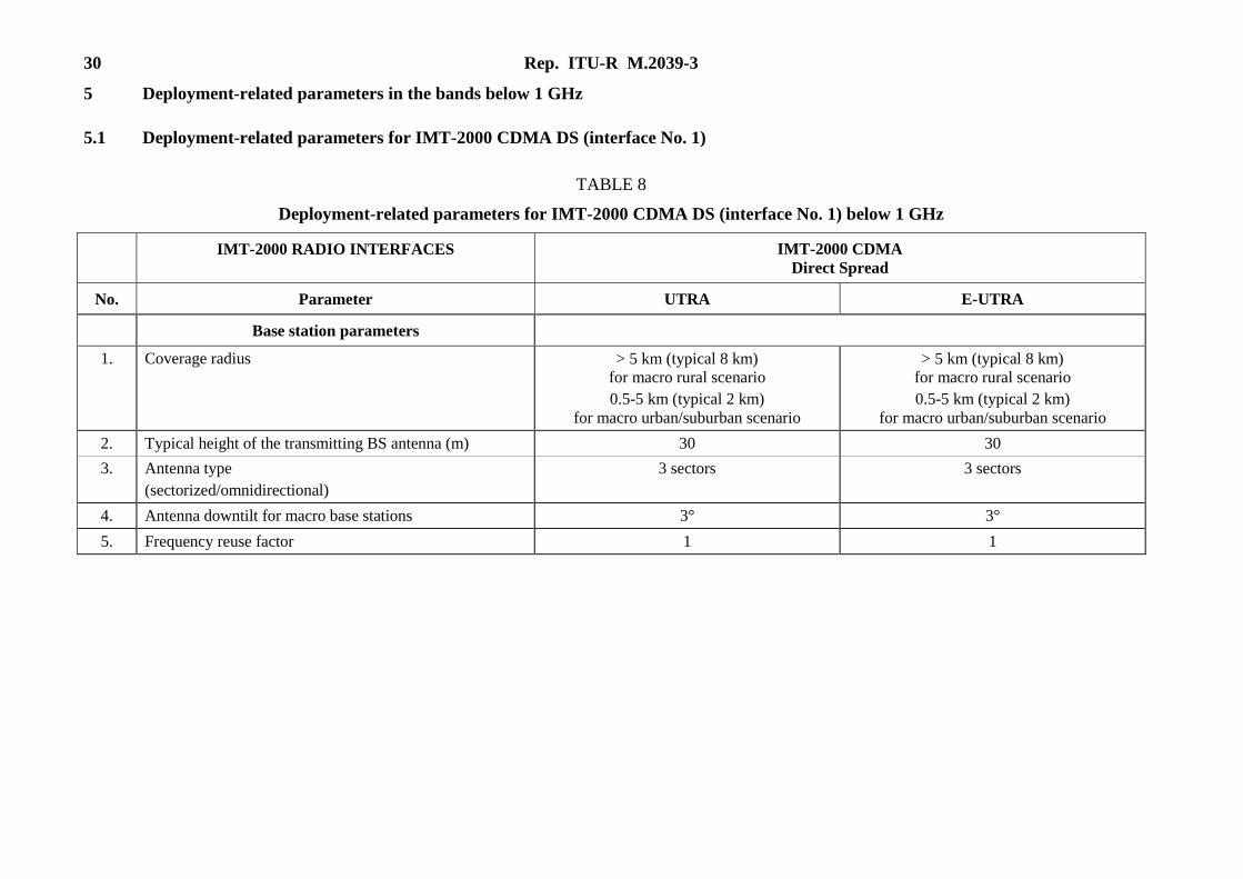
5.1 Deployment-related parameters for IMT-2000 CDMA DS (interface No. 1)
TABLE 8
Deployment-related parameters for IMT-2000 CDMA DS (interface No. 1) below 1 GHz
IMT-2000 RADIO INTERFACES IMT-2000 CDMA
Direct Spread
No. Parameter UTRA E-UTRA
Base station parameters
1. Coverage radius > 5 km (typical 8 km)
for macro rural scenario
0.5-5 km (typical 2 km)
for macro urban/suburban scenario
> 5 km (typical 8 km)
for macro rural scenario
0.5-5 km (typical 2 km)
for macro urban/suburban scenario
2. Typical height of the transmitting BS antenna (m) 30 30
3. Antenna type
(sectorized/omnidirectional)
3 sectors 3 sectors
4. Antenna downtilt for macro base stations 3° 3°
5. Frequency reuse factor 1 1
Rep. ITU-R M.2039-3 31
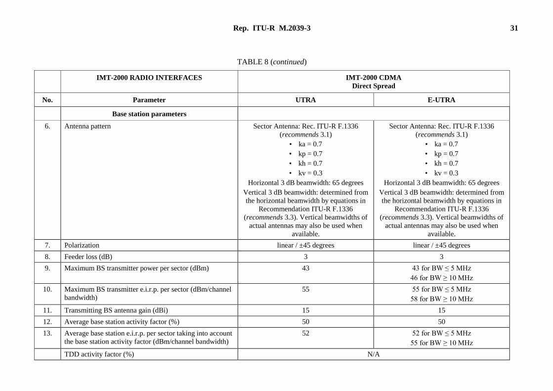
TABLE 8 (continued)
IMT-2000 RADIO INTERFACES IMT-2000 CDMA
Direct Spread
No. Parameter UTRA E-UTRA
Base station parameters
6. Antenna pattern Sector Antenna: Rec. ITU-R F.1336
(recommends 3.1)
• ka = 0.7
• kp = 0.7
• kh = 0.7
• kv = 0.3
Horizontal 3 dB beamwidth: 65 degrees
Vertical 3 dB beamwidth: determined from
the horizontal beamwidth by equations in
Recommendation ITU-R F.1336
(recommends 3.3). Vertical beamwidths of
actual antennas may also be used when
available.
Sector Antenna: Rec. ITU-R F.1336
(recommends 3.1)
• ka = 0.7
• kp = 0.7
• kh = 0.7
• kv = 0.3
Horizontal 3 dB beamwidth: 65 degrees
Vertical 3 dB beamwidth: determined from
the horizontal beamwidth by equations in
Recommendation ITU-R F.1336
(recommends 3.3). Vertical beamwidths of
actual antennas may also be used when
available.
7. Polarization linear / ±45 degrees linear / ±45 degrees
8. Feeder loss (dB) 3 3
9. Maximum BS transmitter power per sector (dBm) 43 43 for BW ≤ 5 MHz
46 for BW ≥ 10 MHz
10. Maximum BS transmitter e.i.r.p. per sector (dBm/channel
bandwidth)
55 55 for BW ≤ 5 MHz
58 for BW ≥ 10 MHz
11. Transmitting BS antenna gain (dBi) 15 15
12. Average base station activity factor (%) 50 50
13. Average base station e.i.r.p. per sector taking into account
the base station activity factor (dBm/channel bandwidth)
52 52 for BW ≤ 5 MHz
55 for BW ≥ 10 MHz
TDD activity factor (%) N/A
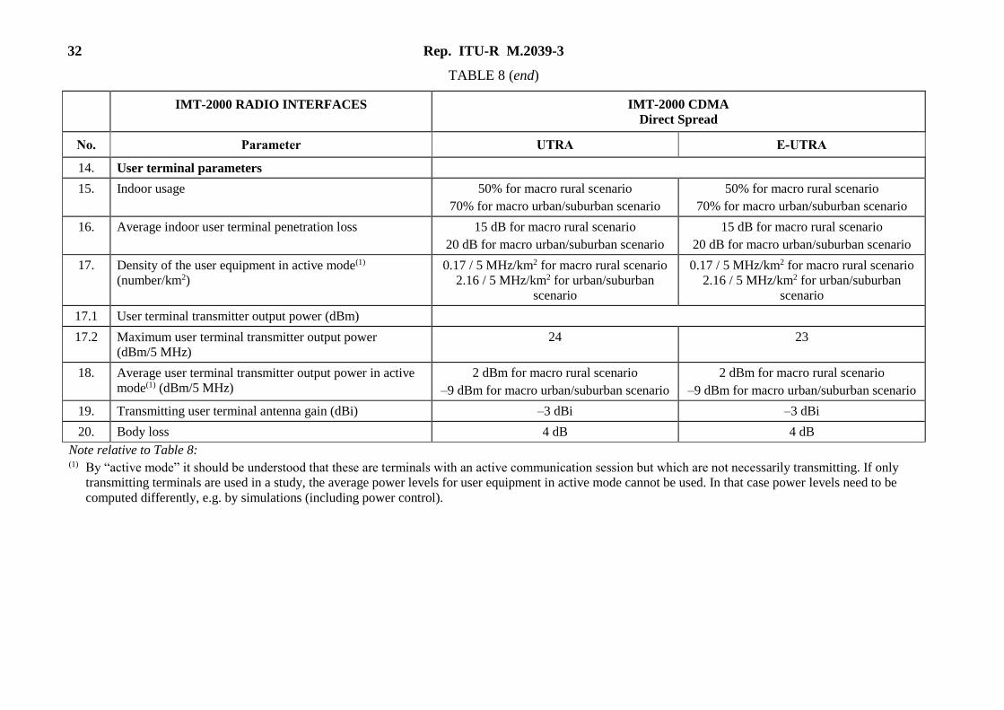
32 Rep. ITU-R M.2039-3
TABLE 8 (end)
IMT-2000 RADIO INTERFACES IMT-2000 CDMA
Direct Spread
No. Parameter UTRA E-UTRA
14. User terminal parameters
15. Indoor usage 50% for macro rural scenario
70% for macro urban/suburban scenario
50% for macro rural scenario
70% for macro urban/suburban scenario
16. Average indoor user terminal penetration loss 15 dB for macro rural scenario
20 dB for macro urban/suburban scenario
15 dB for macro rural scenario
20 dB for macro urban/suburban scenario
17. Density of the user equipment in active mode(1)
(number/km2)
0.17 / 5 MHz/km2 for macro rural scenario
2.16 / 5 MHz/km2 for urban/suburban
scenario
0.17 / 5 MHz/km2 for macro rural scenario
2.16 / 5 MHz/km2 for urban/suburban
scenario
17.1 User terminal transmitter output power (dBm)
17.2 Maximum user terminal transmitter output power
(dBm/5 MHz)
24 23
18. Average user terminal transmitter output power in active
mode(1) (dBm/5 MHz)
2 dBm for macro rural scenario
–9 dBm for macro urban/suburban scenario
2 dBm for macro rural scenario
–9 dBm for macro urban/suburban scenario
19. Transmitting user terminal antenna gain (dBi) –3 dBi –3 dBi
20. Body loss 4 dB 4 dB
Note relative to Table 8: (1) By “active mode” it should be understood that these are terminals with an active communication session but which are not necessarily transmitting. If only
transmitting terminals are used in a study, the average power levels for user equipment in active mode cannot be used. In that case power levels need to be
computed differently, e.g. by simulations (including power control).
Rep. ITU-R M.2039-3 33
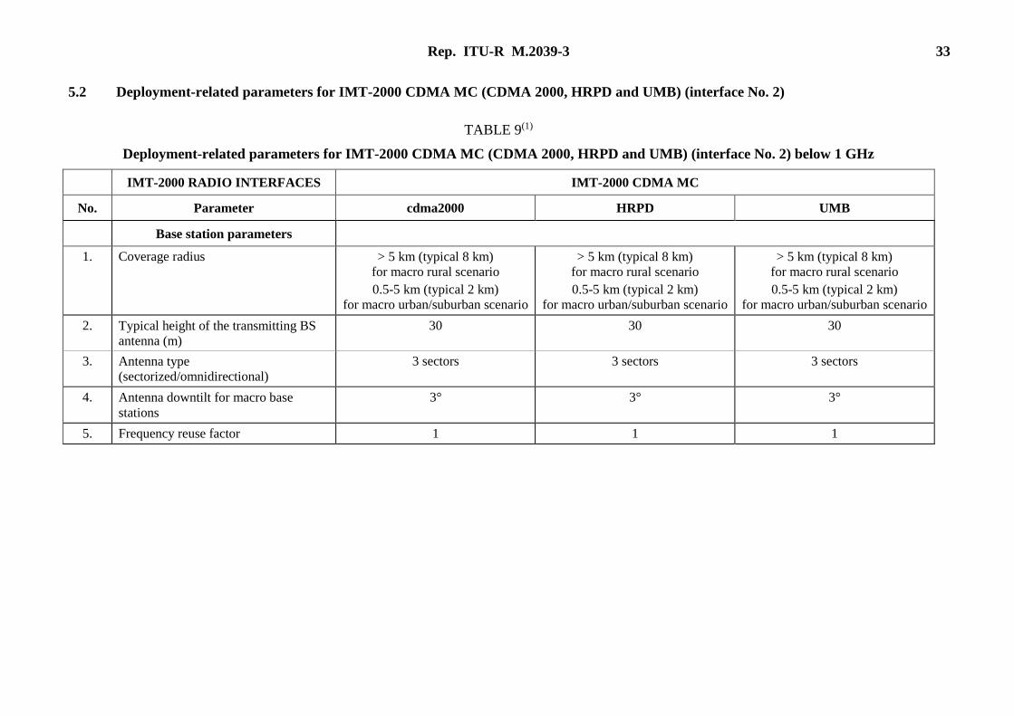
5.2 Deployment-related parameters for IMT-2000 CDMA MC (CDMA 2000, HRPD and UMB) (interface No. 2)
TABLE 9(1)
Deployment-related parameters for IMT-2000 CDMA MC (CDMA 2000, HRPD and UMB) (interface No. 2) below 1 GHz
IMT-2000 RADIO INTERFACES IMT-2000 CDMA MC
No. Parameter cdma2000 HRPD UMB
Base station parameters
1. Coverage radius > 5 km (typical 8 km)
for macro rural scenario
0.5-5 km (typical 2 km)
for macro urban/suburban scenario
> 5 km (typical 8 km)
for macro rural scenario
0.5-5 km (typical 2 km)
for macro urban/suburban scenario
> 5 km (typical 8 km)
for macro rural scenario
0.5-5 km (typical 2 km)
for macro urban/suburban scenario
2. Typical height of the transmitting BS
antenna (m)
30 30 30
3. Antenna type
(sectorized/omnidirectional)
3 sectors 3 sectors 3 sectors
4. Antenna downtilt for macro base
stations
3° 3° 3°
5. Frequency reuse factor 1 1 1
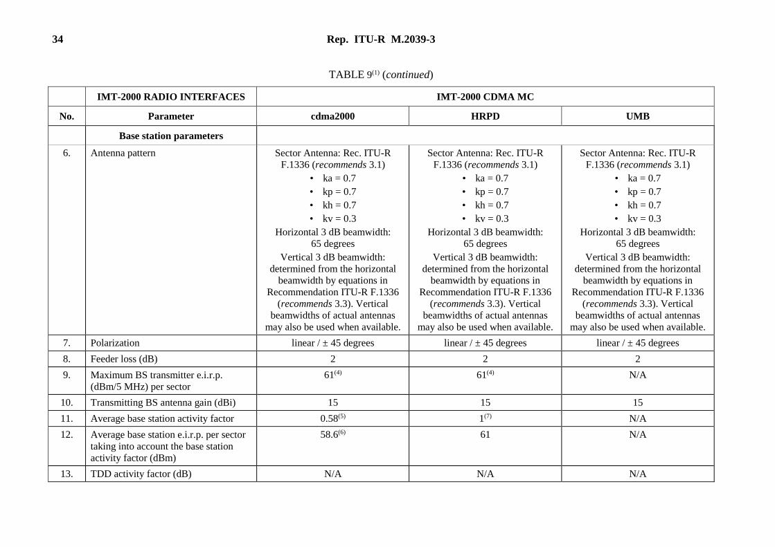
34 Rep. ITU-R M.2039-3
TABLE 9(1) (continued)
IMT-2000 RADIO INTERFACES IMT-2000 CDMA MC
No. Parameter cdma2000 HRPD UMB
Base station parameters
6. Antenna pattern Sector Antenna: Rec. ITU-R
F.1336 (recommends 3.1)
• ka = 0.7
• kp = 0.7
• kh = 0.7
• kv = 0.3
Horizontal 3 dB beamwidth:
65 degrees
Vertical 3 dB beamwidth:
determined from the horizontal
beamwidth by equations in
Recommendation ITU-R F.1336
(recommends 3.3). Vertical
beamwidths of actual antennas
may also be used when available.
Sector Antenna: Rec. ITU-R
F.1336 (recommends 3.1)
• ka = 0.7
• kp = 0.7
• kh = 0.7
• kv = 0.3
Horizontal 3 dB beamwidth:
65 degrees
Vertical 3 dB beamwidth:
determined from the horizontal
beamwidth by equations in
Recommendation ITU-R F.1336
(recommends 3.3). Vertical
beamwidths of actual antennas
may also be used when available.
7. Polarization linear / ± 45 degrees linear / ± 45 degrees linear / ± 45 degrees
8. Feeder loss (dB) 2 2 2
9. Maximum BS transmitter e.i.r.p.
(dBm/5 MHz) per sector
61(4) 61(4) N/A
10. Transmitting BS antenna gain (dBi) 15 15 15
11. Average base station activity factor 0.58(5) 1(7) N/A
12. Average base station e.i.r.p. per sector
taking into account the base station
activity factor (dBm)
58.6(6) 61 N/A
13. TDD activity factor (dB) N/A N/A N/A
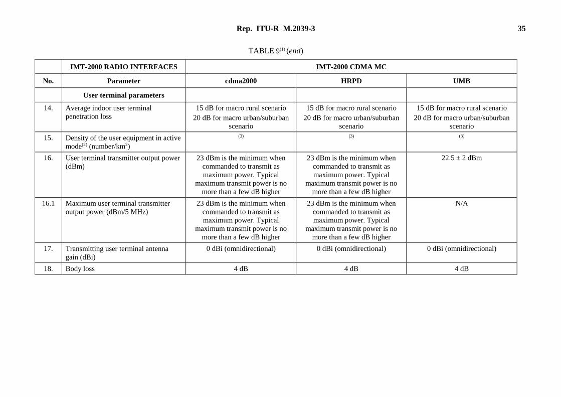
Rep. ITU-R M.2039-3 35
TABLE 9(1) (end)
IMT-2000 RADIO INTERFACES IMT-2000 CDMA MC
No. Parameter cdma2000 HRPD UMB
User terminal parameters
14. Average indoor user terminal
penetration loss
15 dB for macro rural scenario
20 dB for macro urban/suburban
scenario
15 dB for macro rural scenario
20 dB for macro urban/suburban
scenario
15 dB for macro rural scenario
20 dB for macro urban/suburban
scenario
15. Density of the user equipment in active
mode(2) (number/km2)
(3) (3) (3)
16. User terminal transmitter output power
(dBm)
23 dBm is the minimum when
commanded to transmit as
maximum power. Typical
maximum transmit power is no
more than a few dB higher
23 dBm is the minimum when
commanded to transmit as
maximum power. Typical
maximum transmit power is no
more than a few dB higher
22.5 ± 2 dBm
16.1 Maximum user terminal transmitter
output power (dBm/5 MHz)
23 dBm is the minimum when
commanded to transmit as
maximum power. Typical
maximum transmit power is no
more than a few dB higher
23 dBm is the minimum when
commanded to transmit as
maximum power. Typical
maximum transmit power is no
more than a few dB higher
N/A
17. Transmitting user terminal antenna
gain (dBi)
0 dBi (omnidirectional) 0 dBi (omnidirectional) 0 dBi (omnidirectional)
18. Body loss 4 dB 4 dB 4 dB
36 Rep. ITU-R M.2039-3
Notes relative to Table 9: (1) Note that some of the parameters in this table are typically not included in the cdma2000 specifications. These include: maximum spectral power density,
transmitting antenna type, antenna gain, antenna height, antenna pattern, antenna downtilt, feeder loss, and polarization. Some information in these
categories found in this table is listed in 3GPP2 Report C.R1002 (cdma2000 Evaluation Methodology) and may be considered typical in some
deployments. (2) By “active mode” it should be understood that these are terminals with an active communication session but are not necessarily transmitting. If only
transmitting terminals are used in a study, the average power levels for user equipment in active mode cannot be used. In that case power levels need to be
computed differently, e.g. by simulations (including power control). (3) This is a function of frequency, coverage desired, propagation, data rates desired, etc. (4) Assuming 43 dBm per carrier transmit power, 15 dBi antenna gain, 2 dB feeder loss, and 3 carriers within 5 MHz. (5) Assuming 30% overhead power, fully loaded sector, and 40% voice activity factor. (6) Time averaged e.i.r.p. (7) Assuming the base station is fully loaded.
Rep. ITU-R M.2039-3 37
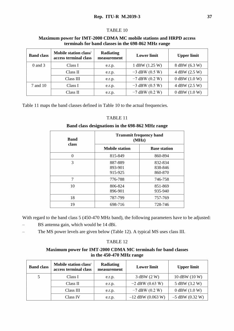
TABLE 10
Maximum power for IMT-2000 CDMA MC mobile stations and HRPD access
terminals for band classes in the 698-862 MHz range
Band class Mobile station class/
access terminal class
Radiating
measurement Lower limit Upper limit
0 and 3 Class I e.r.p. 1 dBW (1.25 W) 8 dBW (6.3 W)
Class II e.r.p. −3 dBW (0.5 W) 4 dBW (2.5 W)
Class III e.r.p. −7 dBW (0.2 W) 0 dBW (1.0 W)
7 and 10 Class I e.r.p. −3 dBW (0.5 W) 4 dBW (2.5 W)
Class II e.r.p. −7 dBW (0.2 W) 0 dBW (1.0 W)
Table 11 maps the band classes defined in Table 10 to the actual frequencies.
TABLE 11
Band class designations in the 698-862 MHz range
Band
class
Transmit frequency band
(MHz)
Mobile station Base station
0 815-849 860-894
3 887-889
893-901
915-925
832-834
838-846
860-870
7 776-788 746-758
10 806-824
896-901
851-869
935-940
18 787-799 757-769
19 698-716 728-746
With regard to the band class 5 (450-470 MHz band), the following parameters have to be adjusted:
– BS antenna gain, which would be 14 dBi.
– The MS power levels are given below (Table 12). A typical MS uses class III.
TABLE 12
Maximum power for IMT-2000 CDMA MC terminals for band classes
in the 450-470 MHz range
Band class Mobile station class/
access terminal class
Radiating
measurement Lower limit Upper limit
5 Class I e.r.p. 3 dBW (2 W) 10 dBW (10 W)
Class II e.r.p. −2 dBW (0.63 W) 5 dBW (3.2 W)
Class III e.r.p. −7 dBW (0.2 W) 0 dBW (1.0 W)
Class IV e.r.p. –12 dBW (0.063 W) –5 dBW (0.32 W)
38 Rep. ITU-R M.2039-3
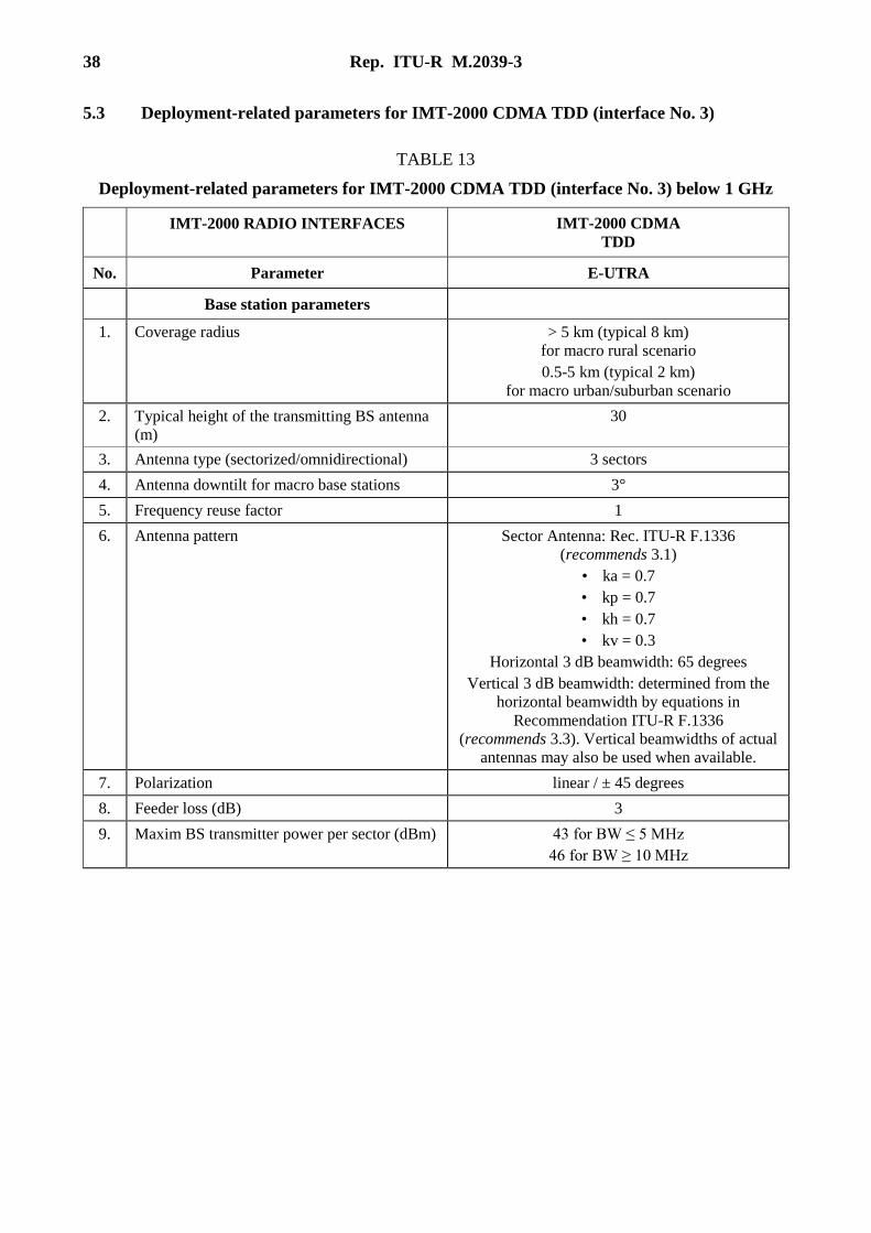
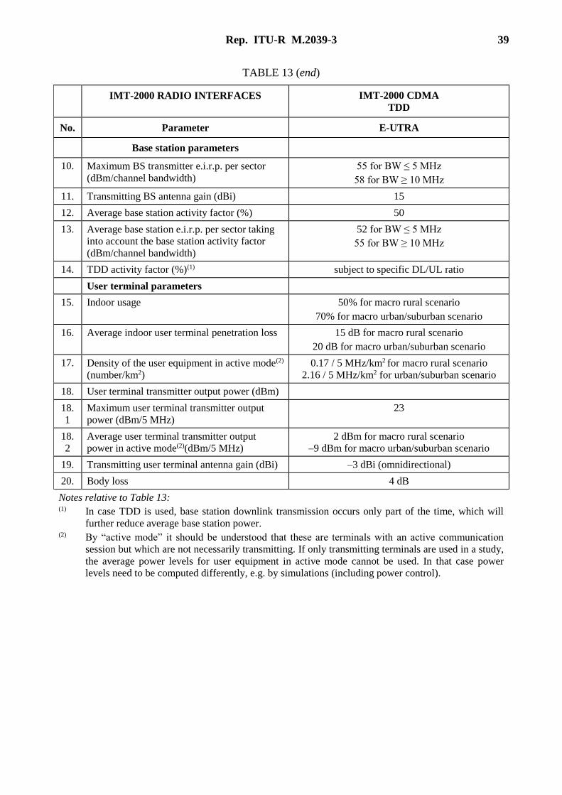
5.3 Deployment-related parameters for IMT-2000 CDMA TDD (interface No. 3)
TABLE 13
Deployment-related parameters for IMT-2000 CDMA TDD (interface No. 3) below 1 GHz
IMT-2000 RADIO INTERFACES IMT-2000 CDMA
TDD
No. Parameter E-UTRA
Base station parameters
1. Coverage radius > 5 km (typical 8 km)
for macro rural scenario
0.5-5 km (typical 2 km)
for macro urban/suburban scenario
2. Typical height of the transmitting BS antenna
(m)
30
3. Antenna type (sectorized/omnidirectional) 3 sectors
4. Antenna downtilt for macro base stations 3°
5. Frequency reuse factor 1
6. Antenna pattern Sector Antenna: Rec. ITU-R F.1336
(recommends 3.1)
• ka = 0.7
• kp = 0.7
• kh = 0.7
• kv = 0.3
Horizontal 3 dB beamwidth: 65 degrees
Vertical 3 dB beamwidth: determined from the
horizontal beamwidth by equations in
Recommendation ITU-R F.1336
(recommends 3.3). Vertical beamwidths of actual
antennas may also be used when available.
7. Polarization linear / ± 45 degrees
8. Feeder loss (dB) 3
9. Maxim BS transmitter power per sector (dBm) 43 for BW ≤ 5 MHz
46 for BW ≥ 10 MHz
Rep. ITU-R M.2039-3 39
TABLE 13 (end)
IMT-2000 RADIO INTERFACES IMT-2000 CDMA
TDD
No. Parameter E-UTRA
Base station parameters
10. Maximum BS transmitter e.i.r.p. per sector
(dBm/channel bandwidth)
55 for BW ≤ 5 MHz
58 for BW ≥ 10 MHz
11. Transmitting BS antenna gain (dBi) 15
12. Average base station activity factor (%) 50
13. Average base station e.i.r.p. per sector taking
into account the base station activity factor
(dBm/channel bandwidth)
52 for BW ≤ 5 MHz
55 for BW ≥ 10 MHz
14. TDD activity factor (%)(1) subject to specific DL/UL ratio
User terminal parameters
15. Indoor usage 50% for macro rural scenario
70% for macro urban/suburban scenario
16. Average indoor user terminal penetration loss 15 dB for macro rural scenario
20 dB for macro urban/suburban scenario
17. Density of the user equipment in active mode(2)
(number/km2)
0.17 / 5 MHz/km2 for macro rural scenario
2.16 / 5 MHz/km2 for urban/suburban scenario
18. User terminal transmitter output power (dBm)
18.
1
Maximum user terminal transmitter output
power (dBm/5 MHz)
23
18.
2
Average user terminal transmitter output
power in active mode(2)(dBm/5 MHz)
2 dBm for macro rural scenario
–9 dBm for macro urban/suburban scenario
19. Transmitting user terminal antenna gain (dBi) –3 dBi (omnidirectional)
20. Body loss 4 dB
Notes relative to Table 13: (1) In case TDD is used, base station downlink transmission occurs only part of the time, which will
further reduce average base station power. (2) By “active mode” it should be understood that these are terminals with an active communication
session but which are not necessarily transmitting. If only transmitting terminals are used in a study,
the average power levels for user equipment in active mode cannot be used. In that case power
levels need to be computed differently, e.g. by simulations (including power control).
40 Rep. ITU-R M.2039-3
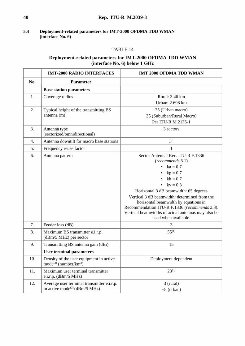
5.4 Deployment-related parameters for IMT-2000 OFDMA TDD WMAN
(interface No. 6)
TABLE 14
Deployment-related parameters for IMT-2000 OFDMA TDD WMAN
(interface No. 6) below 1 GHz
IMT-2000 RADIO INTERFACES IMT 2000 OFDMA TDD WMAN
No. Parameter
Base station parameters
1. Coverage radius Rural: 3.46 km
Urban: 2.698 km
2. Typical height of the transmitting BS
antenna (m)
25 (Urban macro)
35 (Suburban/Rural Macro)
Per ITU-R M.2135-1
3. Antenna type
(sectorized/omnidirectional)
3 sectors
4. Antenna downtilt for macro base stations 3°
5. Frequency reuse factor 1
6. Antenna pattern Sector Antenna: Rec. ITU-R F.1336
(recommends 3.1)
• ka = 0.7
• kp = 0.7
• kh = 0.7
• kv = 0.3
Horizontal 3 dB beamwidth: 65 degrees
Vertical 3 dB beamwidth: determined from the
horizontal beamwidth by equations in
Recommendation ITU-R F.1336 (recommends 3.3).
Vertical beamwidths of actual antennas may also be
used when available.
7. Feeder loss (dB) 3
8. Maximum BS transmitter e.i.r.p.
(dBm/5 MHz) per sector
55(1)
9. Transmitting BS antenna gain (dBi) 15
User terminal parameters
10. Density of the user equipment in active
mode(2) (number/km2)
Deployment dependent
11. Maximum user terminal transmitter
e.i.r.p. (dBm/5 MHz)
23(3)
12. Average user terminal transmitter e.i.r.p.
in active mode(2) (dBm/5 MHz)
3 (rural)
−8 (urban)
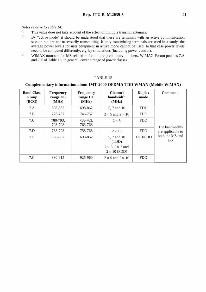
Rep. ITU-R M.2039-3 41
Notes relative to Table 14: (1) This value does not take account of the effect of multiple transmit antennas. (2) By “active mode” it should be understood that these are terminals with an active communication
session but are not necessarily transmitting. If only transmitting terminals are used in a study, the
average power levels for user equipment in active mode cannot be used. In that case power levels
need to be computed differently, e.g. by simulations (including power control). (3) WiMAX numbers for MS related to Item 4 are preliminary numbers. WiMAX Forum profiles 7.A
and 7.E of Table 15, in general, cover a range of power classes.
TABLE 15
Complementary information about IMT-2000 OFDMA TDD WMAN (Mobile WiMAX)
Band Class
Group
(BCG)
Frequency
range UL
(MHz)
Frequency
range DL
(MHz)
Channel
bandwidth
(MHz)
Duplex
mode
Comments
7.A 698-862 698-862 5, 7 and 10 TDD
The bandwidths
are applicable to
both the MS and
BS
7.B 776-787 746-757 2 5 and 2 10 FDD
7.C 788-793,
793-798
758-763,
763-768 2 5 FDD
7.D 788-798 758-768 2 10 FDD
7.E 698-862 698-862 5, 7 and 10
(TDD)
2 5, 2 7 and
2 10 (FDD)
TDD/FDD
7.G 880-915 925-960 2 5 and 2 10 FDD
42 Rep. ITU-R M.2039-3
5.5 Spectrum emission mask for terminal/mobile station equipment operating in the band
3 400-3 600 MHz
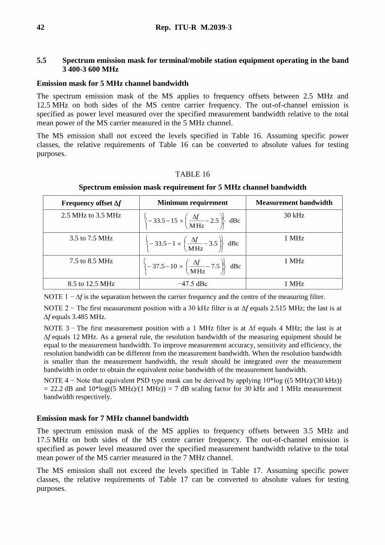
Emission mask for 5 MHz channel bandwidth
The spectrum emission mask of the MS applies to frequency offsets between 2.5 MHz and
12.5 MHz on both sides of the MS centre carrier frequency. The out-of-channel emission is
specified as power level measured over the specified measurement bandwidth relative to the total
mean power of the MS carrier measured in the 5 MHz channel.
The MS emission shall not exceed the levels specified in Table 16. Assuming specific power
classes, the relative requirements of Table 16 can be converted to absolute values for testing
purposes.
TABLE 16
Spectrum emission mask requirement for 5 MHz channel bandwidth
Frequency offset f Minimum requirement Measurement bandwidth
2.5 MHz to 3.5 MHz dBc5.2
MHz155.33
f 30 kHz
3.5 to 7.5 MHz dBc5.3
MHz15.33
f 1 MHz
7.5 to 8.5 MHz dBc5.7
MHz105.37
f 1 MHz
8.5 to 12.5 MHz −47.5 dBc 1 MHz
NOTE 1 − f is the separation between the carrier frequency and the centre of the measuring filter.
NOTE 2 − The first measurement position with a 30 kHz filter is at f equals 2.515 MHz; the last is at
f equals 3.485 MHz.
NOTE 3 − The first measurement position with a 1 MHz filter is at f equals 4 MHz; the last is at
f equals 12 MHz. As a general rule, the resolution bandwidth of the measuring equipment should be
equal to the measurement bandwidth. To improve measurement accuracy, sensitivity and efficiency, the
resolution bandwidth can be different from the measurement bandwidth. When the resolution bandwidth
is smaller than the measurement bandwidth, the result should be integrated over the measurement
bandwidth in order to obtain the equivalent noise bandwidth of the measurement bandwidth.
NOTE 4 − Note that equivalent PSD type mask can be derived by applying 10*log ((5 MHz)/(30 kHz))
= 22.2 dB and 10*log((5 MHz)/(1 MHz)) = 7 dB scaling factor for 30 kHz and 1 MHz measurement
bandwidth respectively.
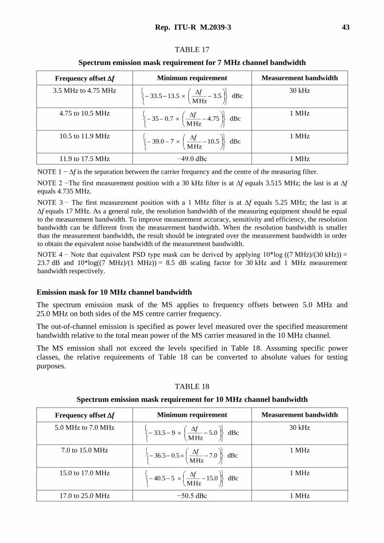
Emission mask for 7 MHz channel bandwidth
The spectrum emission mask of the MS applies to frequency offsets between 3.5 MHz and
17.5 MHz on both sides of the MS centre carrier frequency. The out-of-channel emission is
specified as power level measured over the specified measurement bandwidth relative to the total
mean power of the MS carrier measured in the 7 MHz channel.
The MS emission shall not exceed the levels specified in Table 17. Assuming specific power
classes, the relative requirements of Table 17 can be converted to absolute values for testing
purposes.
Rep. ITU-R M.2039-3 43
TABLE 17
Spectrum emission mask requirement for 7 MHz channel bandwidth
Frequency offset f Minimum requirement Measurement bandwidth
3.5 MHz to 4.75 MHz dBc5.3
MHz5.135.33
f 30 kHz
4.75 to 10.5 MHz dBc75.4
MHz7.035
f 1 MHz
10.5 to 11.9 MHz dBc5.10
MHz70.39
f 1 MHz
11.9 to 17.5 MHz −49.0 dBc 1 MHz
NOTE 1 − f is the separation between the carrier frequency and the centre of the measuring filter.
NOTE 2 −The first measurement position with a 30 kHz filter is at f equals 3.515 MHz; the last is at f
equals 4.735 MHz.
NOTE 3 − The first measurement position with a 1 MHz filter is at f equals 5.25 MHz; the last is at
f equals 17 MHz. As a general rule, the resolution bandwidth of the measuring equipment should be equal
to the measurement bandwidth. To improve measurement accuracy, sensitivity and efficiency, the resolution
bandwidth can be different from the measurement bandwidth. When the resolution bandwidth is smaller
than the measurement bandwidth, the result should be integrated over the measurement bandwidth in order
to obtain the equivalent noise bandwidth of the measurement bandwidth.
NOTE 4 − Note that equivalent PSD type mask can be derived by applying 10*log ((7 MHz)/(30 kHz)) =
23.7 dB and 10*log((7 MHz)/(1 MHz)) = 8.5 dB scaling factor for 30 kHz and 1 MHz measurement
bandwidth respectively.
Emission mask for 10 MHz channel bandwidth
The spectrum emission mask of the MS applies to frequency offsets between 5.0 MHz and
25.0 MHz on both sides of the MS centre carrier frequency.
The out-of-channel emission is specified as power level measured over the specified measurement
bandwidth relative to the total mean power of the MS carrier measured in the 10 MHz channel.
The MS emission shall not exceed the levels specified in Table 18. Assuming specific power
classes, the relative requirements of Table 18 can be converted to absolute values for testing
purposes.
TABLE 18
Spectrum emission mask requirement for 10 MHz channel bandwidth
Frequency offset f Minimum requirement Measurement bandwidth
5.0 MHz to 7.0 MHz dBc0.5
MHz95.33
f 30 kHz
7.0 to 15.0 MHz dBc0.7
MHz5.05.36
f 1 MHz
15.0 to 17.0 MHz dBc0.15
MHz55.40
f 1 MHz
17.0 to 25.0 MHz −50.5 dBc 1 MHz
44 Rep. ITU-R M.2039-3
Notes relative to Table 18:
NOTE 1 − f is the separation between the carrier frequency and the centre of the measuring filter.
NOTE 2 − The first measurement position with a 30 kHz filter is at f equals 510.015 MHz; the last is at f
equals 6.985 MHz.
NOTE 3 − The first measurement position with a 1 MHz filter is at f equals 7.5 MHz; the last is at f
equals 24.5 MHz. As a general rule, the resolution bandwidth of the measuring equipment should be equal to
the measurement bandwidth. To improve measurement accuracy, sensitivity and efficiency, the resolution
bandwidth can be different from the measurement bandwidth. When the resolution bandwidth is smaller
than the measurement bandwidth, the result should be integrated over the measurement bandwidth in order
to obtain the equivalent noise bandwidth of the measurement bandwidth.
NOTE 4 − Equivalent PSD type mask can be derived by applying 10*log ((10 MHz)/(30 kHz)) = 25.2 dB
and 10*log((10 MHz)/(1 MHz)) = 10 dB scaling factor for 30 kHz and 1 MHz measurement bandwidth
respectively.
References
[1] 3GPP TS 25.101: 3rd Generation Partnership Project; Technical Specification Group Radio Access
Networks; UE Radio Transmission and Reception (FDD) (Release 9).
[2] 3GPP TS 36.101: 3rd Generation Partnership Project; Technical Specification Group Radio Access
Networks; Evolved Universal Terrestrial Radio Access (E-UTRA); User Equipment (UE) radio
transmission and reception (Release 9).
[3] 3GPP TS 25.104 v9.3.0 (2010-03): 3rd Generation Partnership Project; Technical Specification
Group Radio Access Networks; BS Radio Transmission and Reception (FDD) (Release 9).
[4] 3GPP TR 25.951: 3rd Generation Partnership Project; Technical Specification Group Radio Access
Networks, FDD Base Station Classification (Release 9).
[5] 3GPP TS 36.104: 3rd Generation Partnership Project; Technical Specification Group Radio Access
Networks; Evolved Universal Terrestrial Radio Access (E-UTRA); Base Station (BS) radio
transmission and reception (Release 9).
[6] TIA-97-H; Recommended minimum performance Standards for cdma2000® spread spectrum base
stations, Feb 2012.
[7] TIA-98-H; Recommended minimum performance Standards for cdma2000® spread spectrum
mobile stations, April 2012.
[8] TIA-864-D; Recommended minimum performance Standards for cdma2000® High Rate Packet
Data Access Network, May 2012.
[9] TIA-866-D; Recommended minimum performance Standards for cdma2000® High Rate Packet
Data Access Terminal, May 2012.
[10] TIA-1170: Recommended Minimum Performance Standards for cdma2000 Ultra Mobile
Broadband (UMB) Access Network, February 2010.
[11] TIA-1171: Recommended Minimum Performance Standards for cdma2000 Ultra Mobile
Broadband Access Terminal, February 2010.
[12] 3GPP TS 25.102: 3rd Generation Partnership Project; Technical Specification Group Radio Access
Networks; UE Radio Transmission and Reception (TDD) (Release 9).
[13] 3GPP TS 25.105: 3rd Generation Partnership Project; Technical Specification Group Radio Access
Networks; BS Radio Transmission and Reception (TDD) (Release 9).
[14] TR45 technical specification, SP-4027-270b); Mobile Station Minimum Performance, clause 1.4
and clause 3.2.2. Refers To Power Class Ii Mobile Station.
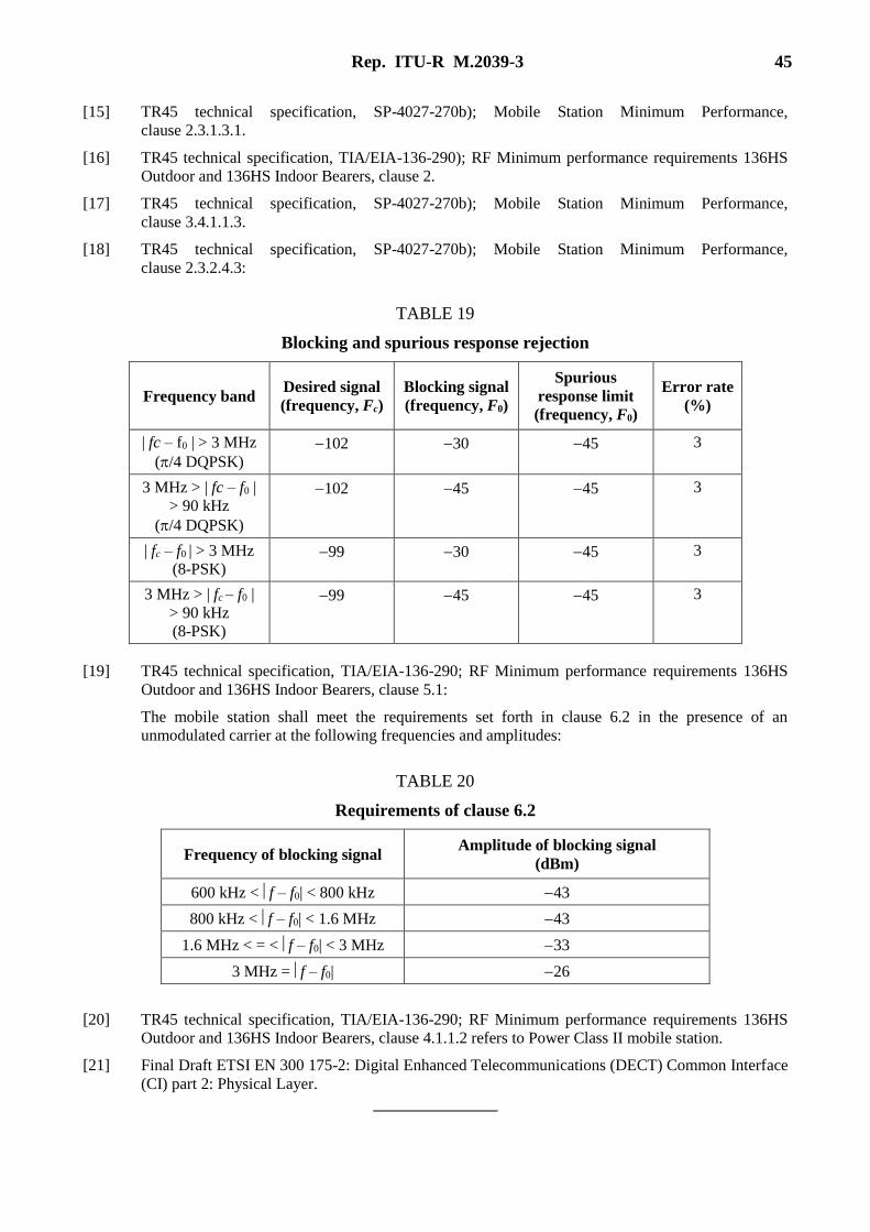
Rep. ITU-R M.2039-3 45
[15] TR45 technical specification, SP-4027-270b); Mobile Station Minimum Performance,
clause 2.3.1.3.1.
[16] TR45 technical specification, TIA/EIA-136-290); RF Minimum performance requirements 136HS
Outdoor and 136HS Indoor Bearers, clause 2.
[17] TR45 technical specification, SP-4027-270b); Mobile Station Minimum Performance,
clause 3.4.1.1.3.
[18] TR45 technical specification, SP-4027-270b); Mobile Station Minimum Performance,
clause 2.3.2.4.3:
TABLE 19
Blocking and spurious response rejection
Frequency band Desired signal
(frequency, Fc)
Blocking signal
(frequency, F0)
Spurious
response limit
(frequency, F0)
Error rate
(%)
| fc – f0 | > 3 MHz
(/4 DQPSK)
102 30 45 3
3 MHz > | fc – f0 |
> 90 kHz
(/4 DQPSK)
102 45 45 3
| fc – f0 | > 3 MHz
(8-PSK) 99 30 45 3
3 MHz > | fc – f0 |
> 90 kHz
(8-PSK)
99 45 45 3
[19] TR45 technical specification, TIA/EIA-136-290; RF Minimum performance requirements 136HS
Outdoor and 136HS Indoor Bearers, clause 5.1:
The mobile station shall meet the requirements set forth in clause 6.2 in the presence of an
unmodulated carrier at the following frequencies and amplitudes:
TABLE 20
Requirements of clause 6.2
Frequency of blocking signal Amplitude of blocking signal
(dBm)
600 kHz < f – f0| < 800 kHz 43
800 kHz < f – f0| < 1.6 MHz 43
1.6 MHz < = < f – f0| < 3 MHz 33
3 MHz = f – f0| 26
[20] TR45 technical specification, TIA/EIA-136-290; RF Minimum performance requirements 136HS
Outdoor and 136HS Indoor Bearers, clause 4.1.1.2 refers to Power Class II mobile station.
[21] Final Draft ETSI EN 300 175-2: Digital Enhanced Telecommunications (DECT) Common Interface
(CI) part 2: Physical Layer.