Embed Size (px)
Citation preview

Characteristics of Steel Plate Shear Walls With
Infill Plates Strengthened by GFRP Laminates:
Experimental Investigation
Masoud Khazei-Poul*
M.Sc Graduated, Structural Engineering Research Center, International Institute
of Earthquake Engineering and Seismology (IIEES), 19395 Tehran, Iran
Fariborz Nateghi-Alahi Professor, Structural Engineering Research Center, International Institute of
Earthquake Engineering and Seismology (IIEES), 19395 Tehran, Iran
nateghi @iiees.ac.ir
SUMMARY:
In composite steel plate shear walls system, steel web plates can be strengthened by adding a number of layers of
fiber reinforced polymer laminate or concrete on one or both sides of the web plate. In this paper, nonlinear
behavior of composite steel plate shear wall systems, in which steel infill plate is strengthened by fiber
reinforced polymer (FRP) layers, are experimentally investigated. Experimental models are scaled one-story
steel shear panel model, with hinge type connections of boundary elements at four corners. In the first test,
unstiffened steel infill plate is used for test. In the next four tests, strengthened steel infill plates are being used
with different number and orientation of GFRP layers. Each test was performed under fully reversed cyclic
quasi-static loading in the elastic and inelastic response zones of the specimens, in compliance with ATC-24
(1992) test protocol. The experimental results indicate that by strengthening infill steel plate yield strength,
ultimate shear strength and cumulative dissipated energy can be significantly increased.
Keywords: Steel plate shear wall; Composite; GFRP; Fiber orientation, Stiffness
1. INTRODUCTION
Steel plate shear wall (SPSW) systems have significant advantage over many other systems in term of
cost, primarily, substantial ductility, high initial stiffness, fast pace of construction, and the reduction
in seismic mass. SPSW system can be used in different configurations, such as stiffened, un-stiffened
thin steel plate, and composite steel plate. Unstiffened steel plate shear wall is the basis for SPSW
systems. This type of web plate has negligible compression strength and shear buckling occurs at low
levels of loading. Lateral load are resisted through diagonal tension in the web plate. Stiffened web
may also be used to increase shear buckling strength. In this type, the strength is a combination of
shear buckling strength and additional strength from diagonal tension action. In composite steel plate
shear walls (CSPSWs) system, steel web plates can be stiffened by adding concrete on one or both
sides of the web plate. Concrete layers can improve load carrying capacity of SPSWs by permitting
utilization of the full yield strength of the infill plate. In addition, shear strength of the concrete is
effective to increase capacity of system. Steel infill plate can be strengthened by adding number of
layers of fiber reinforced polymer laminate in both sides. In this type of CSPSW, like unstiffened
SPSW systems, strengthened steel plate has negligible compression strength and shear buckling occurs
at low levels of loading. FRP laminate layers are effective to increase post buckling strength, initial
and secant stiffness of the system.
During the four last decades many experimental and numerical research on seismic performance of un-
stiffened and stiffened SPSW have been carried out and these researches lead to better understanding
of this lateral load resistant system. Wagner is the first researcher who used a complete and uniform
tension fields to determine the shear strength of a panel with rigid flanges and very thin web, and
inferred that the shear buckling of a thin aluminum plate supported adequately on its edges does not
constitute failure. Other researches were also conducted based on this idea to develop an analytical
method for modeling of thin SPSW. Thorburn et al. developed a simple analytical method to evaluate
the shear strength of unstiffened SPSWs with thin steel plates and introduced the strip model to
represent the tension field action of a thin steel wall subjected to shear forces. Timler and Kulak
modified the formula for the angle of strips inclination with the column by the tests. Elaghy
experimentally investigated behavior of SPSW and proposed an analytical model to determine the
behavior of thin steel plate shear walls. Berman and Bruneau presented plastic analysis method based
on the strip models as an alternative for the design of SPSW. This method has been implemented into
the Canadian design codes for steel structure (CAN/CSA 2001) and the AISC (2005b) seismic design
specifications. Sabouri-Gohomi et al. proposed Plate-Frame-Interaction (PFI) method to predict the
shear behavior of the SPSWs. Kharrazi et al. presented modified plate frame interaction (M-PFI)
method for use in the design of steel plate wall systems. Khazaei-Poul and Nategh-Alahi proposed an
analytical model, the Composite-Plate Frame Interaction (C-PFI) method, to predict the shear behavior
of the strengthened steel plate shear walls by FRP Laminate, and they showed C-PFI method is able to
properly predict the shear behavior of the C-SPSW systems. They showed fiber orientation is an
important variable on the seismic behavior of the C-SPSW. They reported if principal orientation of
GFRP laminates is oriented in the direction of tension fields, the shear strength and stiffness of C-
SPSW will reach the maximum possible value
Astaneh-Asl performed experimental tests on the two specimens of three-story C-SPSW under cyclic
loads. They showed the concrete layer produces a better distribution of stress in the steel plate and
developing tension field lines in a wider region. Rahai and Hatami experimentally and numerically
investigated the effects of shear studs spacing variation, middle beam rigidity and the method of beam
to column connection on the C-SPSW behavior.
Lubell et al. tested two single and one 4-story thin SPSWS under cyclic loading and compared the
experimental results with the simplified tension field analytical models and found that the models can
predict post-yield strength of the specimens well, with less satisfactory in the elastic stiffness results.
Caccese et al. tested five one-fourth scale models of three-story into the effects of panel slender ratio
and type of beam-to-column connection. They reported as the plate thickness increased, the failure
mode was governed by column instability and the difference between simple and moment-resisting
beam-to- column connection was small. Driver et al. tested a 4-story large-scale steel plate shear wall
specimen with unstiffened panels under cyclic loading to determine its behavior under an idealized
severe earthquake event. Robert and Sabouri-Gohomi conducted a series of 16 quasi-static loading
tests on unstiffened steel plate shear panel with central opening. Vian et al. performed test on special
perforated SPSW with reduced beam section anchor beams under cyclic loading and reported the
perforated panel reduced the elastic stiffness and overall strength of the specimen by 15% as compared
with the solid panel specimen.
Alinia and Dastfan studied the effect of surrounding members on the overall behavior of thin steel
plate shear walls. His results show that the flexural stiffness of the surrounding members has no
significant effect on elastic shear buckling or the post-buckling behavior of the shear walls.
In this paper, nonlinear behaviour of composite steel plate shear walls has been experimentally
investigated. In this regard, five experiments have been conducted. Experimental models are scaled
one-story steel shear panel models, with hinge type connections of boundary elements at four corners.
Steel infill plates are strengthened by number of GFRP laminate layers with different orientation and
all specimens are subjected to quasi-static loading.
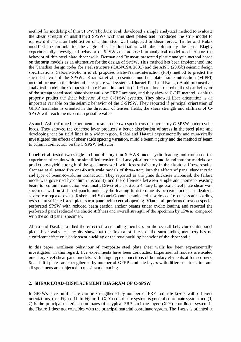
2. SHEAR LOAD–DISPLACEMENT DIAGRAM OF C-SPSW
In SPSWs, steel infill plate can be strengthened by number of FRP laminate layers with different
orientations, (see Figure 1). In Figure 1, (X-Y) coordinate system is general coordinate system and (1,
2) is the principal material coordinates of a typical FRP laminate layer. (X-Y) coordinate system in
the Figure 1 dose not coincides with the principal material coordinate system. The 1-axis is oriented at
anangleof+γcounterclockwisefromtheX-axis (see Figure 1).In(X′- Y′)coordinatesystem,X′-axis
isorientedalongthedirectionoftensionfieldandatanangleof+θcounterclockwisefromtheX-axis.
FRP layers can be attached to steel infill plate by adhesive. If a perfect bond is considered at the bond
between adhesive and steel infill plate interface and between FRP layers and also it is assumed that
delamination does not occur in the FRP layers, shear load–displacement diagram of composite steel
plate shear wall can be approximately obtained by superimposing the shear load–displacement
diagrams of frame and composite steel plate as shown in Figure 2. In C-SPSW after yielding of the
steel infill plate, system will have a secant stiffness that it is provided by FRP laminate layers.
Figure 1. Composite steel plate shear wall Figure 2. Shear load–displacement diagram of C-SPSW
(Khazaei-Poul and Nateghi-Alahi 2012)
Notations: UCSP.cr Limiting elastic displacement of composite steel plate UCSP.cr The limiting elastic shear displacement Uwpb Shear displacement of the post-buckled component UFry
The limiting elastic shear displacement of the frame
D Displacements larger yielding point of the frame and composite steel plate
FCSPSW.UCSP.cr Total shear force of the CSPSWs at UCSP.cr (correspond to the buckling limit)
FCSPSW.UCSP.y Total shear force of the CSPSWs at UCSP.y (corresponds to the yielding point of
the steel plate in composite steel plate) FCSPSW.UFr.y
Total shear force of the CSPSWs at Ufr.y (corresponds to the yielding point of the
frame)
FCSPSW.D Total shear force of the CSPSWs at D (corresponds to displacements larger
yielding point of the frame and composite steel plate FCSPy
Limiting elastic shear force of composite steel plate
FFr.y The shear strength of the frame Fwpb Shear strength of the composite steel plate due to formation of tension field lines Kcomp.plate.sec Equivalent secant stiffness of the composite steel plate Kfr Stiffness of frame Kcomp.plate Stiffness of the composite steel plate Kw Stiffness of steel plate Keq.lam Equivalent stiffness of FRP laminate layers
3. EXPERIMENTAL STUDY
To investigate and to evaluate the effect of glass fiber polymer on the seismic behaviour of steel plate
shear wall, several tests were performed on scaled models of steel plate shear panel. For this purpose,
five tests have been conducted. Experimental models are scaled one-story steel shear panel models,
with hinge type connections of boundary elements at four corners. In the first test unstiffened steel
infill plate are used for test. In the next tests, steel infill plates are strengthened by numbers of GFRP
layers with different orientations. In this study, infill plate is strengthened by four methods of
arranging the FRP laminate on the infill steel plate. Each test was performed under fully reversed
cyclic quasi-static loading in the elastic and inelastic response zones of the specimens, in compliance
with ATC-24 (1992) test protocol by means of a hydraulic jack with 600 kN capacity.
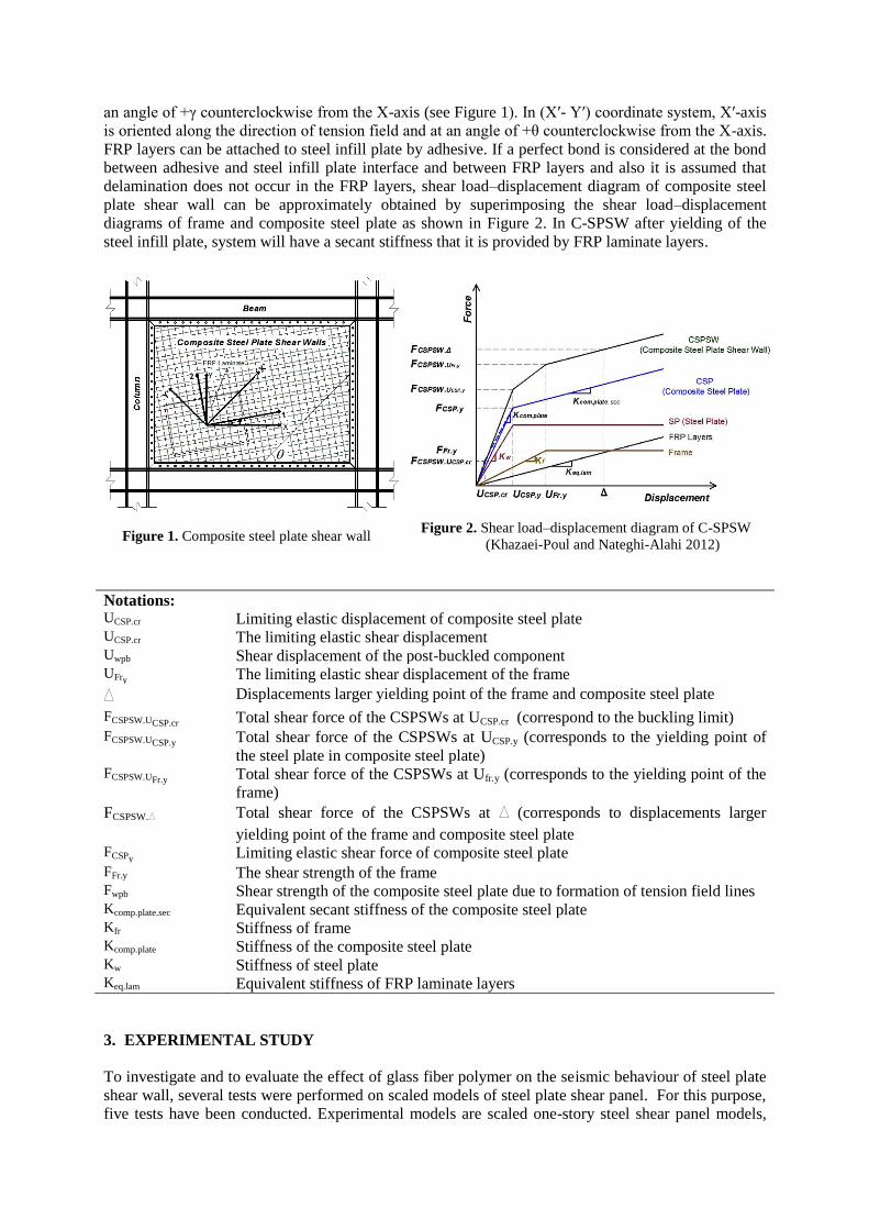
3.1. Test Set-Up and Experimental Models
For experimental study, the number of cyclic loading tests on small-scale, unstiffened steel plate shear
panel (SPSP) and composite steel plate shear panel (CSPSP) were conducted. A scaled one-story steel
shear panel model, with hinge type connections of boundary elements at four corners, is selected.
Details of the test experimental specimens are presented in Figure 3. The edges of the steel and
composite plate were clamped between pairs of rigid frame members by means of two rows of high
tensile bolts. Bolts with a diameter of 10 mm are used for connections of infill steel plate to
surrounding frame. The boundary elements of the specimen are similar, while the infill steel plate
thickness is 0.9 mm. Specimen consisted of the standard profile double section UNP100, as boundary
elements. The boundary elements were also such designed to meet the preliminary requirements of
steel plate shear walls and AISC 341-05 provisions. The all specimen’sdepthandwidthareequalto
600 mm while depth and width of infill plates are equal to 400 mm.
a: Dimension of the experimental model b: View of test set-up
c: View of specimen and support details
Figure 3. Test set-up and specimen detail (dimension in mm)
Details of the all experimental models are presented in Table 1. In the first experimental specimen
(SPSP1) unstiffened steel plate with thickness of 0.9 mm is selected for infill plate. In the next models
steel infill plate has been stiffened by numbers of GFRP layers with different orientation of GFRP
laminated layers that are showed in Figure 4. In the CSPSP2 and CSPSP3 specimen, composite steel
plate with approximately total thickness of 1.916 mm is selected for infill plate. Composite steel plate
in the CSPSP2 and CSPSP3 specimens are consisted of steel infill plate whit thickness of 0.9 mm that

is strengthened by one layer of GFRP laminate in each side. In the CSPSP2 specimen principal
orientation of GFRP laminate (the direction that laminate have maximum amount of strength and
young modules) are oriented a +45 and -45 inclination with angle with tension fields (α= 0 and
90) Figure 4-a . In the CSPSP3 specimen principal orientation of GFRP laminate are oriented in
directionoftensionfields(α=0and90)Figure 4-b. In the CSPSP4 and CSPSP5 specimen, composite
steel plate with approximately total thickness of 2.932 mm is selected for infill plate. Composite steel
plate in the CSPSP4 and CSPSP5 specimens are consisted of steel infill plate whit thickness of 0.9 mm
that is strengthened by two layer of GFRP laminate in each side. In the CSPSP4 specimen principal
orientation of GFRP laminate are oriented a +45 and -45 inclination with angle withtensionfields(α=
0 and 90) Figure 4-c. In the CSPSP5 specimen principal orientation of GFRP laminate are oriented in
directionoftensionfields(α=0and90)Figure 4-d.
Table 1. Details of the Experimental Models
Experimental
models
Number of layers
in composite infill
plate (mm)
Thickness of
laminate and steel
plate (mm)
total
thickness
of infill
plate
(mm)
Orientation of GFRP GFRP Type
Steel
plate
GFRP
layer
Steel
plate
GFRP
layer
SPSP1 1 0 0.9 mm - 0.9 - -
CSPSP2 1 2 0.9 mm 0.508 1.916 0 # 90 SikaWrap®
Hex 430G
CSPSP3 1 2 0.9 mm 0.508 1.916 45 # -45 SikaWrap®
Hex 430G
CSPSP4 1 4 0.9 mm 0.508 2.932 0 & 90 # 0 & 90 SikaWrap®
Hex 430G
CSPSP5 1 4 0.9 mm 0.508 2.932 45 & -45 # 45 & -45 SikaWrap®
Hex 430G
a: CSPSP2: one layer GFRP laminate in each side of
infillplate;α=0&90
b: CSPSP3: one layer GFRP laminate in each side of
infillplate;α=+45&-45
c: CSPSP4: two layers GFRP laminate in each side
of infillplate;α=0&90
d: CSPSP5: two layers GFRP laminate in each side of
infillplate;α=+45&-45
Figure 4. Different types of strengthening of the infill steel plate by GFRP laminates
The SikaWrap-Hex-430G is applied to strengthen steel plates in all experimental specimens.
SikaWrap-Hex-430G is a unidirectional glass fiber fabric. The structural adhesive Sikadur-330 was
used to bond the composite overlays. The method of application using a grooved roller ensured that
the adhesive dispersed uniformly through the fibers. Consequently, a thin layer of epoxy adhesive was
formed at the steel and GFRP laminate interface and they worked together with the epoxy in-between
the fiber laminates. Total thickness of each GFRP laminate used adhesive is 0.508 mm based on
technical data provided by the manufacturer.
3.2. Material Properties
Tests were conducted to determine the stress- strain relationship of the infill steel plate and boundary
element materials used in the experimental models. All tests were conducted on specimen
dimensioned as proposed in ASTMA370-05. Yield stress and young module of infill steel plate based
on the mean of static tests are equal to 180 MPa and 204 GPa, respectively and for boundary element
(UNP100) those are equal to 310 MPa and 203 GPa, respectively. The failure strains were
approximately 32% for steel infill plate and 19% for UNP100.
Steel infill plates were strengthened by SikaWrap-Hex-430G. Unidirectional GFRP laminate have
almost linear behaviour the final failure. Based on the technical data provided by the manufacturer, the
longitudinal modulus (Ex) and the longitudinal tensile strength (Tx) of the cured SikaWrap-Hex-430G
Laminate with Sikadur 330 Epoxy, which is dominated by the properties of the fiber, is equal to 26.49
GPa and 537 MPa, respectively. The transverse modulus (Ey) and the transverse tensile strength (Ty)
perpendicular are equal to 7.07 GPa and 23 MPa. The longitudinal and transverse failure strains of the
GFRP laminate approximately are equal to 2.2% and 0.46%, respectively. Mechanical property of
GFRP laminate is presented in Table 2. TheYoung’smoduliandTensileStrengthofSikadur-330 are
3489 MPa and 60.6 MPa, respectively.
Table 2. Mechanical Property of The GFRP Laminate
GFRP Material Tensile Modulus Tensile Strength
Ex (GPa) Ey (GPa) Tx (MPa) Ty(MPa)
SikaWrap® Hex 430G 6.49 7.07 537 23
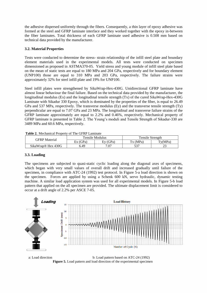
3.3. Loading
The specimens are subjected to quasi-static cyclic loading along the diagonal axes of specimens,
which began with very small values of overall drift and increased gradually until failure of the
specimen, in compliance with ATC-24 (1992) test protocol. In Figure 5-a load direction is shown on
the specimen. Forces are applied by using a Schenk 600 kN, servo hydraulic, dynamic testing
machine. A similar load application system was used for all experimental models. In Figure 5-b load
pattern that applied on the all specimen are provided. The ultimate displacement limit is considered to
occur at a drift angle of 2.2% per ASCE 7-05.
a: Load direction b: Load pattern based on ATC-24 (1992)
Figure 5. Load pattern and load direction of the experimental specimen

3.4. Discussion of Analytical Results
Hysteretic load-displacement curves for the specimens are presented in Figure 6. In Table 3, the
amount of stiffness, yield strength, and ultimate strength of the specimens based on
experimental hysteresis curve are presented. These results show that adding GFRP layers can be
increased initial stiffness of specimens.
a: SPSP1 specimen b: CSPSP2 specimen
c: CSPSP2 specimen d: CSPSP2 specimen
e: CSPSP2 specimen
Figure 6. Hysteretic curve of the experimental specimens
-20 -10 0 10 20-200
-150
-100
-50
0
50
100
150
200
Displacement (mm)
Fo
rce
(k
N)
-20 -10 0 10 20-200
-150
-100
-50
0
50
100
150
200
Displacement (mm)
Fo
rce
(k
N)
-20 -10 0 10 20-200
-150
-100
-50
0
50
100
150
200
Displacement (mm)
Fo
rce
(k
N)
Experimental ------
-20 -10 0 10 20-200
-150
-100
-50
0
50
100
150
200
Displacement (mm)
Fo
rce
(k
N)
Experimental ------
-20 -10 0 10 20-200
-150
-100
-50
0
50
100
150
200
Displacement (mm)
Fo
rce
(k
N)
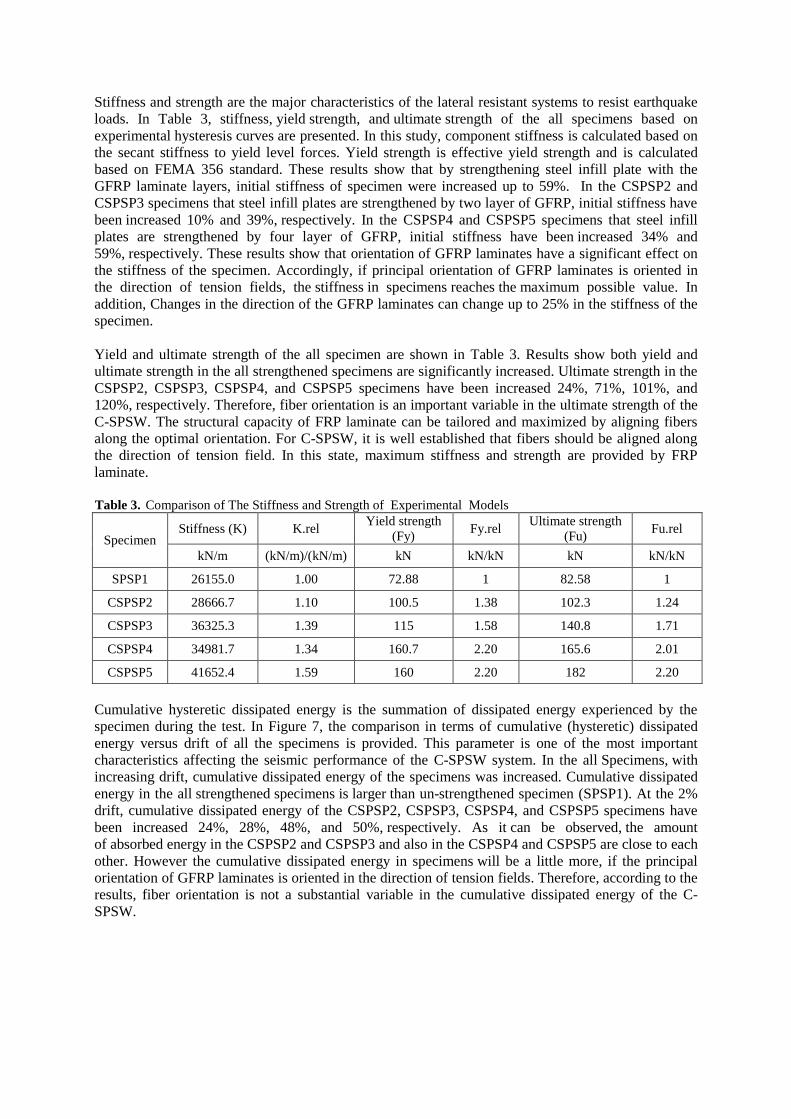
Stiffness and strength are the major characteristics of the lateral resistant systems to resist earthquake
loads. In Table 3, stiffness, yield strength, and ultimate strength of the all specimens based on
experimental hysteresis curves are presented. In this study, component stiffness is calculated based on
the secant stiffness to yield level forces. Yield strength is effective yield strength and is calculated
based on FEMA 356 standard. These results show that by strengthening steel infill plate with the
GFRP laminate layers, initial stiffness of specimen were increased up to 59%. In the CSPSP2 and
CSPSP3 specimens that steel infill plates are strengthened by two layer of GFRP, initial stiffness have
been increased 10% and 39%, respectively. In the CSPSP4 and CSPSP5 specimens that steel infill
plates are strengthened by four layer of GFRP, initial stiffness have been increased 34% and
59%, respectively. These results show that orientation of GFRP laminates have a significant effect on
the stiffness of the specimen. Accordingly, if principal orientation of GFRP laminates is oriented in
the direction of tension fields, the stiffness in specimens reaches the maximum possible value. In
addition, Changes in the direction of the GFRP laminates can change up to 25% in the stiffness of the
specimen.
Yield and ultimate strength of the all specimen are shown in Table 3. Results show both yield and
ultimate strength in the all strengthened specimens are significantly increased. Ultimate strength in the
CSPSP2, CSPSP3, CSPSP4, and CSPSP5 specimens have been increased 24%, 71%, 101%, and
120%, respectively. Therefore, fiber orientation is an important variable in the ultimate strength of the
C-SPSW. The structural capacity of FRP laminate can be tailored and maximized by aligning fibers
along the optimal orientation. For C-SPSW, it is well established that fibers should be aligned along
the direction of tension field. In this state, maximum stiffness and strength are provided by FRP
laminate.
Table 3. Comparison of The Stiffness and Strength of Experimental Models
Specimen Stiffness (K) K.rel
Yield strength
(Fy) Fy.rel
Ultimate strength
(Fu) Fu.rel
kN/m (kN/m)/(kN/m) kN kN/kN kN kN/kN
SPSP1 26155.0 1.00 72.88 1 82.58 1
CSPSP2 28666.7 1.10 100.5 1.38 102.3 1.24
CSPSP3 36325.3 1.39 115 1.58 140.8 1.71
CSPSP4 34981.7 1.34 160.7 2.20 165.6 2.01
CSPSP5 41652.4 1.59 160 2.20 182 2.20
Cumulative hysteretic dissipated energy is the summation of dissipated energy experienced by the
specimen during the test. In Figure 7, the comparison in terms of cumulative (hysteretic) dissipated
energy versus drift of all the specimens is provided. This parameter is one of the most important
characteristics affecting the seismic performance of the C-SPSW system. In the all Specimens, with
increasing drift, cumulative dissipated energy of the specimens was increased. Cumulative dissipated
energy in the all strengthened specimens is larger than un-strengthened specimen (SPSP1). At the 2%
drift, cumulative dissipated energy of the CSPSP2, CSPSP3, CSPSP4, and CSPSP5 specimens have
been increased 24%, 28%, 48%, and 50%, respectively. As it can be observed, the amount
of absorbed energy in the CSPSP2 and CSPSP3 and also in the CSPSP4 and CSPSP5 are close to each
other. However the cumulative dissipated energy in specimens will be a little more, if the principal
orientation of GFRP laminates is oriented in the direction of tension fields. Therefore, according to the
results, fiber orientation is not a substantial variable in the cumulative dissipated energy of the C-
SPSW.
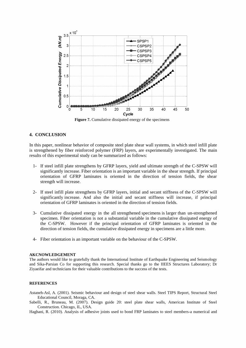
Figure 7. Cumulative dissipated energy of the specimens
4. CONCLUSION
In this paper, nonlinear behavior of composite steel plate shear wall systems, in which steel infill plate
is strengthened by fiber reinforced polymer (FRP) layers, are experimentally investigated. The main
results of this experimental study can be summarized as follows:
1- If steel infill plate strengthens by GFRP layers, yield and ultimate strength of the C-SPSW will
significantly increase. Fiber orientation is an important variable in the shear strength. If principal
orientation of GFRP laminates is oriented in the direction of tension fields, the shear
strength will increase.
2- If steel infill plate strengthens by GFRP layers, initial and secant stiffness of the C-SPSW will
significantly increase. And also the initial and secant stiffness will increase, if principal
orientation of GFRP laminates is oriented in the direction of tension fields.
3- Cumulative dissipated energy in the all strengthened specimens is larger than un-strengthened
specimen. Fiber orientation is not a substantial variable in the cumulative dissipated energy of
the C-SPSW. However if the principal orientation of GFRP laminates is oriented in the
direction of tension fields, the cumulative dissipated energy in specimens are a little more.
4- Fiber orientation is an important variable on the behaviour of the C-SPSW.
AKCNOWLEDGEMENT
The authors would like to gratefully thank the International Institute of Earthquake Engineering and Seismology
and Sika-Parsian Co for supporting this research. Special thanks go to the IIEES Structures Laboratory; Dr
Ziyaeifar and technicians for their valuable contributions to the success of the tests.
REFERENCES
Astaneh-Asl, A. (2001). Seismic behaviour and design of steel shear walls. Steel TIPS Report, Structural Steel
Educational Council, Moraga, CA.
Sabelli, R., Bruneau, M. (2007). Design guide 20: steel plate shear walls, American Institute of Steel
Construction. Chicago, IL, USA.
Haghani, R. (2010). Analysis of adhesive joints used to bond FRP laminates to steel members-a numerical and
experimental study. Construction and building materials Vol 24; Number 11, pages 2243-2251
Zhao X-L, Zhang L. (2007). State-of-the-art review on FRP strengthened steel structures. Engineering Structures
Vol. 29(8):1808–23.
Photiou, NK., Hollaway, LC., Chryssanthopoulos, MK. (2002). Strengthening of an artificially degraded steel
beam utilising a carbon/glass composites system. 2nd international conference on advances polymer
composites for structural applications in construction. Guildford, UK: Woodhead Publishing Limited.
Khazaei-Poul M, Natghi-Alahi F.(2011). Behavior of strengthened steel plate shear wall by FRP laminate. M.Sc.
Thesis. International Institute Of Earthquake Engineering and Seismology, Iran.
Nateghi-Alahi, F., Khazaei-Poul, M. (2012). Analytical study on the strengthened steel plate shear walls by FRP
laminate. The 2nd International Conference on Rehabilitation and Maintenance in Civil Engineering.
(ICRMCE-2), B32-105, Solo, Indonesia.
Wagner, H. (1931). Flat sheet metal girders with very thin webs. Part i. General theories and assumptions. Tech
Memo. National Advisory Committee for Aeronautics, Washington D. C. No. 604.
Thorburn LJ, Kulak GL, Montgomery CJ. (1983). Analysis of steel plate shear walls. Structural engineering
report 107. Edmonton (Alberta, Canada).
Timler PA, Kulak GL. (1983). Experimental study of steel plate shear walls. Structural Engineering Report,
University of Alberta, Canada, , No. 114.
Elgaaly, M. (1998). Thin steel plate shear walls behavior and analysis. Thin walled Structures Vol. 32,151-180
Berman, JW., Bruneau, M. (2003). Plastic analysis and design of steel plate shear walls. Journal of Structural
Engineering Vol. 129,11, 1148–1156.
CAN/CSA S16-2001. Limit state design of steel structures. Canadian Standards Association, Willowdale, ON.,
Canada.
AISC (2005b). Specifications for structural steel buildings, American Institute of Steel Construction, Chicago,
IL., USA.
Sabouri-Ghomi, S., Ventura, C., Kharrazi, HK. (2005). Shear analysis and design of ductile steel plate walls.
Journal of Structural Engineering, Vol. 131, No. 6, June 1.
Kharrazi, MHK. (2005). Rational method for analysis and design of steel plate walls. Ph.D. dissertation.
Vancouver (Canada): University of British Columbia.
Khazaei-Poul, M., Nateghi-Alahi, F. (2012). Theoretical and numerical study on the strengthened steel plate
shear walls by FRP laminates, International Journal of Engineering, IJE TRANSACTIONS C: ASPECTS,
Vol. 25, No. 1, p. 25-37.
Astaneh-Asl A. (2000). Seismic studies of innovative and traditional composite shear walls. Research project in-
progress, Dept of Civil and Env Engineering: Univ. of California, Berkeley.
Astaneh-Asl A. (2001). Cyclic tests of steel shear walls. Research project. Berkeley: Dept of Civil and Env
Engineering, Univ of California.
Rahai, A., Hatami, F. (2009). Evaluation of composite shear wall behavior under cyclic loadings. Journal of
Constructional Steel Vol. 65(7):1528–37.
Lubell, AS., Prion, HGL., Ventura, CE., Rezai, M. (2000). Un-stiffened steel plate shear wall performance
under cyclic loading. Journal of Structural Engineering, Vol. 126, No. 4, p. 453-460.
Caccese, V., Elgaaly, M., Chen, R. (1993). Experimental study of thin steel-plate shear walls under cyclic load.
ASCE Journal of Structural Engineering, Vol. 119, No. 2, p. 573-587.
Driver, RG., Kulak, GL., Kennedy, DJL. (1998). Cyclic tests of four-story steel plate shear wall. ASCE Journal
of Structural Engineering, Vol. 124, No. 2, p. 112-120.
Sabouri-Ghomi, S., Roberts, TM. (1992). Nonlinear dynamic analysis of steel plate shear walls including shear
and bending deformations, Engineering Structures, Vol. 14, no.5, pp. 309 317.
Vian, D., Bruneau, M., Tsai, KC., Lin, YC. (2009). Special perforated steel plate shear walls with reduced beam
section anchor beams. I: Experimental investigation. Journal of Structural Engineering Vol. 135, No. 3.
Alinia, MM. (2005). A study into optimization of stiffeners in plates subjected to in- plane shear loads. Thin-
Walled Structures Vol. 43(4):845-60.
Alinia, MM., Dastfan, M. (2006). Behaviour of thin steel plate shear walls regarding frame members. Journal of
Constructional Steel Research Vol. 62:730-8. ATC. (1992). Guidelines for cyclic seismic testing of components of steel structures for buildings. Rep. No.
ATC-24, Applied Technology Council, Redwood City, Calif.
ASTM, A-370- 03. (2003). Standard Test Methods and Definitions for Mechanical Testing of Steel Products.
ASTM International, 100 Barr Harbor Drive, PO Box C700, West Conshohocken, PA 19428-2959, United
States.


![GFRP [Hand lay up]](https://img.pdfslide.us/doc/110x75/557cb1dcd8b42abf328b4c0e/gfrp-hand-lay-up.jpg)