Embed Size (px)
Citation preview

CHARACTERISTICS OF MOTION ERRORS OF 3 –AXIS CNC VERTICAL
MILLING MACHINES
AZMAN BIN AHMAD BAKIR
A project report submitted in partial fullfilment of the
requirements for the award of the degree of
Master of Engineering (Advance Manufacturing Technology)
Faculty of Mechanical Engineering
Universiti Teknologi Malaysia
APRIL 2010

iii
ACKNOWLEDGEMENT
The author would like to dedicate this thesis to his wife and family and thank
them for their support and patience throughout this research. He would not have been
able work on this thesis without their moral and financial support to fund this research.
Their helping hands always reached out to help him during the most difficult times. He
also would like to thank his thesis supervisor Associate Professor Zainal Abidin bin
Ahmad for his encouragement, guidance and critics throughout this research. In
preparing this thesis, he was in contact with many people, researchers, academicians,
and practitioners. They have contributed towards his understanding and thoughts
My sincere appreciation also extends to all my colleagues and others who have
provided assistance at various occasions. Their views and tips are useful indeed.
Unfortunately, it is not possible to list all of them in this limited space. I am grateful to
all my family members.

iv
ABSTRACT
This project presents a systematic approach to understand the different types of
motion errors exist in Computer Numerical Controlled (CNC) machines. This research
focused on five units of identical CNC milling machines, that is, the same brand, model
and years of operation. As the increasing number of CNC machines in manufacturing
field, there is a need to ensure the machines are in good running condition. Machine
tools such as CNC vertical milling machines are meant to produce precise workparts,
therefore is important to maintain their accuracy. Periodic and preventive maintenance
of the machine is crucial, whereby motion error inspection is one of predictive
maintenance activities in ensuring CNC machines are in good working condition. The
purpose of this project is to find out any abnormalities to the machine performance. The
motion errors of CNC machines were analysed by using Double Ball Bar (DBB)
measuring device. This equipment is designed to analyse the machine performance by
measuring the accuracy of its movements. This device having two identical size balls at
the end of the bar was mounted on spindle and onto a special holder which is mounted
on the working table. The machine is made to move in a circular motion, clockwise and
anti-clockwise in three planes, XY, YZ and ZX. Any deviation from the standard data
will represent the imperfection of machine condition especially mechanical components
such as slide bearing, spindle bearing or servo motor responses. Based on the study,
DBB equipment has successfully captured the motion errors of five units of 3-axis CNC
vertical milling machines. Diagnosis has been done and several error origins have been
presented in this study. By knowing the most significant error origin, the corrective
countermeasures can be carried out.

v
ABSTRAK
Kajian ini di lakukan untuk memahami kewujudan pelbagai jenis ralat gerakan
dalam pemesinan CNC pengisar. Kajian ini akan tertumpu kepada mesin CNC pengisar
yang sama jenis, pembuat dan jangka hayat.Peningkatan pengunaan mesin CNC di
dalam bidang pembuatan, telah wujud kepentingan untuk memastikan mesin yang
diguna sentiasa dalam keadaan yang baik. Pemesinan mesin seperti CNC pengisar amat
mementingkan untuk mencapai ketepatan yang tertentu.Oleh sebab itu, penyelengaraan
ramalan adalah penting untuk memastikan mesin sentiasa berada dalam keadaan
memuaskan.Pemeriksaan ralat gerakan untuk mesin CNC pengisar adalah selari dengan
kehendak penyelenggaraan ramalan. Tujuan aktiviti tersebut adalah untuk mendapat
sebarang bentuk kecacatan pada prestasi mesin.Ralat pergerakan akan diukur dengan
mengunakan alat pengukur yang di kenali sebagai “double ball bar”. Kegunaan
peralatan tersebut adalah untuk mengukur ketepatan mesin dalam pergerakan. Peralatan
ini akan di pasang pada “spindle” dan pada permukaan mesin dengan mengunakan
peralatan yang khusus.Sebarang bentuk penyimpangan pada data pada peralatan
tersebut, menunjukkan ketidak sempurnaan komponen mesin terutama bahagian
mekanikal seperti galas pada “spindle, galas pada “working table”, motor servo dan
banyak lagi.Berdasarkan kajian yang di buat, peralatan tersebut telah berjaya merakam
beberapa ralat gerakan pada 5 mesin yang di kaji.Diagnostik pada ralat tersebut telah
dikaji dan punca ralat tersebut telah di bentangkan dalam kajian ini. Punca ralat tersebut
adalah amat berguna kepada pemilik mesin untuk membuat tindakan susulan.

vi
TABLE OF CONTENTS
CHAPTER TITLE PAGE
DECLARATION ii
ACKNOWLEDGEMENTS iii
ABSTRACT iv
ABSTRAK v
TABLE OF CONTENTS vi
LIST OF TABLES ix
LIST OF FIGURES x
LIST OF ABBREVIATIONS xv
LIST OF SYMBOLS xvi
LIST OF APPENDICES xvii
CHAPTER I INTRODUCTION
1.0 Introduction 1
1.2 Background and rationale 6
1.2.1 Research Objectives 6
1.2.2 Research scope 6
1.3 Research problem and hypotheses 8
1.3.1 Statement of research problem 8

vii
1.3.2 Research questions 8
1.3.3 Research hypotheses 9
CHAPTER II LITERATURE REVIEW
2.1 Literature review 10
2.1.1 Research regarding CNC milling motion accuracy errors 10
2.1.2 Research regarding equipment for measuring motion 12
Accuracy errors
2.2 Conclusion 14
CHAPTER III METHODOLOGY
3.1 Methodology 15
3.2 Measuring methods and procedures 16
3.3 Data evaluation and analysis method 18
3.4 Accuracy Tests Definition 20
3.5 Definition of errors 23
3.6 Equipment and tool definition 31
3.7 Double ball bar equipment 37
CHAPTER IV MEASUREMENT AND DIAGNOSTIC PROCEDURE
4.1 Introduction 47
4.2 Methods for performing accuracy test 46

viii
CHAPTER V RESULT AND DISCUSSION
5.1 Introduction 58
5.2 Machine no. 24 60
5.3 Machine no. 19 71
5.4 Machine no.17 82
5.5 Machine no.13 92
5.6 Macgine no. 14 101
5.7 Counter measure of error 109
CHAPTER VI CONCLUSIONS AND FUTURE WORK
6.1 Conclusions 114
6.2 Comparison with commissioning manufacturer data 119
6.3 Future work 120
REFERENCES 122
APPENDICES 125

ix
LIST OF TABLES
TABLE NO. TITLE PAGE
5.0 Uncertainties for machine center (Al.Lakmiz et al) 60
(Y.Kakino et.al)
5.1 Summary of motion accuracy and diagnosis table of 61
Machine no. 24, CNC HASS 3 axis vertical milling,
Serial no. 36759
5.2 Sumaary of double ball bar analysis of machine19. 73
CNC HASS 3 axis vertical milling, serial 37050
5.3 Summary of table motion analysis and diagnosis of 85
5.4 Analysis and diagnosis of machine 13,CNC HASS 3 94
5.5 Machine no.14, CNC HASS, 3 axis vertical milling 103
Serial no.36736

x
LIST OF FIGURES
FIGURE NO. TITLE PAGE
1.0 Flow chart represents the scope of work 6
3.0 A typical vertical type milling center 23
3.1 Structure of vertical type machining centre shown in 24
(Y.Kakino et al,1993)
3.2 Structure of the horizontal type of machining center 29
(Y.Kakino et al,1993)
3.3 Detecting part of DBB device (Y. Kakino et al,1993) 32
3.4 Method using master ring gauge and displacement type probe 33
(Y.Kakino)
3.5 Machining of a disk by endmill and profile error of machine 33
Surface(Measurement of roundness error)(Y.Kakino et al,1993)
3.6 Coordiante and error vector in DBB measurement 35
(Y.Kakino et al 1993)
3.7 Detecting part of DBB device (Y.Kakino et al,1993) 36
3.8 Data processing system in DBB method (Y.Kakino,al et) 37
3.9 Calibration gauge for DBB device(Y.Kakino et al) 38
3.10 Roundness profile of spindle magnetic socket(Y.Kakino et al,1993) 39
3.11 Measuring method for rotating accuracy socket by roundness 40
Measuring machine(Y.Kakino,al et,1993)

xi
FIGURE NO. TITLE PAGE
3.12 Measuring results of the rotating accuracy of socket by 42
a roundness measuring machine (Y.Kakino et al 1993)
3.13 Rotating accuracy of socket and ball measured by differential 43
Type transducer (Y.Kakino et al,1993)
3.14 Method of definining compensation (Y.Kakino et al,1993) 43
4.0 Setup to determine the zero position fixed socket 48
4.1 The installation of double ball bar to both sockets 49
4.2 Evaluation error in axial direction (Y.Kakino,et al ,1993) 51
4.3 Evaluation of the mismatching of position loop 52
(Y.Kakino et al,1993)
4.4 Cyclic motion error (Y.Kakino,et al,1993) 53
4.5 Evaluation steep and projection (Y.Kakino et al, 1993) 54
4.6 Evaluation of gentle slope (Y.Kakino et al,1993) 54
4.7 Evaluation of lag intercepts in axial (Y.Kakino et al,1993) 55
4.8 Evaluation of intercept path between CW and CCW traces 55
(Y.Kakino, et al,1993)
5.0 The relation of significant error at various feedrate(Machine no.24) 63
5.1 The squareness error at XY (Machine no. 24) 64
5.2 The squareness error at YZ (Machine no.24) 65
5.3 2nd order straightness ZX in feedrate (Machine no.24) 66
5.4 2nd order straightness YZ vs feedrate (Machine no.24) 66
5.5 X,Y roundness error at different reference points ,clockwise 67
Motion (Machine no.24)
5.6 XY roundness at different reference points ,counter clockwise 68
Motion( Machine no. 24)

xii
FIGURE NO. TITLE PAGE
5.7 Circular graphical of XY axis (Machine no. 24) 69
5.8 Circular graphical of ZX axis (Machine no. 24) 69
5.9 Circular graphical of YZ axis (Machine no. 24) 70
5.10 Radar chart of machine error analysis(Machine no.24) 71
5.11 Relation of XY scale error to both direction 75
5.12 Squareness error of XY axis vs feedrate (Machine no.19) 76
5.13 2nd order straightness vs feedrate (Machine no. 19) 76
5.14 Mismatching loop gain vs feedrate (Machine no. 19) 77
5.15 Relation of scale error vs feedrate both direction (Machine no.19) 77
5.16 Roundness error versus feedrate at different reference points with 78
Counterclockwise direction (Machine no.19)
5.17 Roundness error versus feedrate at different point with clockwise 78
(Machine no.19)
5.18 XY axis at feed 600m/min (Machine no. 19) 79
5.19 ZX deviation graph at 600m/min feedrate (Machine no.19) 81
5.20 YZ axis deviation 600m/min (Machine no.19) 81
5.21 The radar chart of significant error (Machine no. 19) 82
5.22 Scale error XY against feedrate 86
5.23 Squareness YZ against feedrate 87
5.25 ZX 2nd order straightness against feedrate 87
5.26 YZ 2nd order straightness against feedrate 88

xiii
5.27 XY roundness against feedrate at diff. Reference pts at clockwise 89
5.28 Squareness YZ against feedrate 90
5.29 The motion trace pattern XY 91
5.30 The motion trace patern ZX 91
5.31 Trace patern for YZ axis 92
5.32 Distribution of most significant error (Machine no. 17) 92
5.33 Squareness YZ axis against feedrate 96
5.34 2nd order straightness ZX 96
5.35 2nd order straightness YZ against feedrate 97
5.36 XY roundness against feedrate reference points of clockwise 98
Motion
5.37 XY roundness against feedrate at difference point of counter 98
Clockwise
5.38 The motion trace XY axis of feedrate of 600 m/min 99
5.39 The motion trace of ZX axis at feedrate of 600m/min 100
5.40 The motion trace of YZ at feedrate of 600m/min 100
5.41 Significant error of machine 13 101
5.42 Scale error XY versus feedrate 105
5.43 Squareness YZ against feedrate 105
5.44 Straightness 2nd order against feedrate 106
5.45 Motion trace of XY circular deviation 107
6.0 Roundness error against machine 115
6.1 Bi-repeatability against machine 116
6.2 Scale error of XY against machine 117

xiv
6.3 Squareness error versus machine 118
6.4 Second order straightness error versus machine 118
6.5 Mismatching gain loop error versus machine 119
6.6 Machine performance according diagnostic errors 120
6.7 Circularity error of commissioning versus existing stage 121

xv
ABBREVIATIONS
ABBREVIATIONS DESCRIPTION
NC Numerical Control
CNC Computer Numerical Control
DBB Double ball bar
ASME American Society of Mechanical Engineers
ANSI American Standard Institute
DC Direct Current
LVDT Linear variable differential transformer
JIS Japanese Institute Standard
MZCRW Minimum Zone Centre Radial Width
PCRW Polar center radius centre
CW Clockwise direction
CW Counter Clockwise direction
PID Proportional Integral Devices

xvi
LIST OF SYMBOLS
X,Y,Z = Direction of nominal axis
Cx = Error vector in X-axis
Cy = Error vector in Y-axis
Cz = Error vector in Z-axis
x,y,z = Direction of linear motion
a,b,c = Rotation around X,Y,Z
Pw = Workpiece clampn on table
Ps = On spindle base
Ay,by,cy = Angular motion
exX = Positioning error of X-Axis feed
eyX = Straightness in Y axis
ezX = Straightness in Z-axis
Xs, Ys = Centre offset
Rs = Centre offset
m = Mirometer
= Angular velocity

xvii
LIST OF APPENDICES
NO. TITLE PAGE
A MOTION ERROR TRACE 126
B MANUFACTURING COMMISIONING DATA 142
C GENERAL PROCEDURE OF SETTING DOUBLE BALLBAR 147

CHAPTER 1
INTRODUCTION
1.0 Introduction
This project presents a systematic approach to understand the different types of
motion errors existed in CNC machines. This research was focused on five identical
units of CNC machines with same brand, model and years of operation. As the
increasing number of CNC machines in manufacturing field, there is a need to ensure
the machines are at good running condition. Machine tool such as CNC vertical milling
machines is important to achieve certain machine accuracy. Therefore periodic and
preventive maintenance of the machine is crucial.
Now days, the predictive maintenance has grown to become popular in
maintenance activities. This is due to the current CNC machines have become more
complicated, integrated and expensive. The costs of parts or components are expensive
and uneconomic to use regular preventive maintenance system. The predictive
maintenance has been reputed as the most suitable types of maintenance activities.

2
Motion error characteristics are one of predictive maintenance in CNC machines. The
purpose of this research is to find out any abnormalities to machine performance. This
machine performance will convert to high quality product. These motion errors of CNC
are analysed by using Double Ball Bar (DBB). This equipment is designed to analyse
the machine performance by measuring the accuracy of its movements.
This device having two identical size balls at the end of the bar was mounted on
spindle and onto a special holder which is mounted on the working table. The machine
is made to move in a circular motion, clockwise and anti-clockwise in three planes, XY,
YZ and ZX. Any deviation from the standard data will represent the imperfection of
machine condition especially mechanical components such as slide bearing, spindle
bearing or servo motor responses.
The ANSI/ASME B.5.54-1991 standard method of performance evaluation of
computer numerically controlled machining centres was need in the analysis. Motion
error analysis is actually the analysis of contouring performance of the machine. This
involved machine servo motor performance, feedback performance, mechanical
structure and servo control system.
The data obtained from the measurement was analysed based on previous
recorded data from manufacture. This data is actually based on historical records made
by actual machine performance. This type of maintenance activities should be
performed at early stage of machine life. When the machine is new, the motion error
analysis should be recorded as the reference for future analysis. Machine performance
will be deteriorated, as time passing by therefore it’s a crucial to compare the reference
data which has been taken at early stage with the existing machine condition. Any
deviation from the data shows the machine performance. The research is focused on the
on circular type of motion errors.

3
Data from this analysis is essential for maintenance engineer to predict a failure
and make necessary actions to resolve the issue. There several methods for measuring
circular motion accuracy which are double ball bar method, master ring and a
displacement type probe method besides direct cutting test. Double ball bar is selected
for this research, because of its simplicity and yet capable of giving high accurate result.
The equipment is suitable also for predictive maintenance usage to record and diagnose
machine condition. The double ball equipment used as the measurement tool is from
Heidenhain double ball bar 110. This equipment also is equipped with software to ease
data retrieving and diagnosis guides.
Maintenance is one crucial aspect in manufacturing engineering. It started with
Industrial evolution, where parts or components are massively produced. Machine is
designed to produce all of the required components in massive volume. Even though
that, long hours operation requires the machine to be maintained to avoid unnecessary
breakdown. At early stage, they still can afford to have a machine breakdown since the
machine is manually operated and the machine is simple thus easy to repair. At this
stage, they practice breakdown maintenance, which seems suits to their requirement of
operation.
In new modern manufacturing industry, machine has become more efficient,
complicated and fully automated. This type of new generation machines only required
fewer man powers to operate because of automation functions. Thus this new feature,
able to increase the volume of production but it requires new maintenance principles.
This new machine cannot afford to breakdown, since the investment cost of the machine
is high. Each downtime is a lost for the investor. From economic point of view, in order
to produce part at effective cost is by producing at high volume. Machine components
become expensive which requires new type of maintenance to cater this problem.

4
There several new maintenance principles which are preventive maintenance,
condition based maintenance and predictive maintenance. Preventive maintenance is an
activity performs based on periodic basis. For example replacement of bearing in DC
motor is scheduled 5 years once. This means every 5 years the bearing must be replaced
even though the condition still good. This type of maintenance is suitable for low cost
mechanical and several electrical components. For high expensive components and
electronic components condition based maintenance is more suitable. Condition based
maintenance is based on scheduled inspection of desired parts. Parts are only replaced if
it is damaged. This will reduce the maintenance cost, but this type of maintenance
requires regular checking and checking equipment which are quite expensive. This type
of maintenance also always combined with predictive maintenance which helps in
performing maintenance at effective method. Compare to preventive maintenance,
condition based and predictive maintenance is the best maintenance program for
ensuring and preserving machine performance.
Motion errors analysis is one of condition and predictive maintenance for CNC
machine application. Double ball bar is a device to measure the volumetric errors which
consists of two high precision ball and magnetic sockets. The system can measure the
distance between two points of the balls with high accuracy.
Figure 1.0 : Double ball bar device

5
5 identical Vertical CNC machines with 5 years of operation were used for this
research. From this analysis, it is hoped to discover a few errors, Thereby will able to
help reducing maintenance cost without jeopardize machine performance.
Figure 1.1 : Vertical CNC milling machine

6
1.2 Background and rationale
1.2.1 Research Objectives
The primary factor that influences machining accuracy is the motion accuracy of
the machine tool. When there is a motion error in a machine tool, it will be transferred to
the machined profile and thus increases the profile error of the machined surface.
Therefore, knowing the motion accuracy is indispensable for high precision machining.
If the dimensional error and the profile error of the elements of a machine tool are large,
the motion accuracy will be bad. It is also influenced by the assembly and the
adjustment of the control system.The main objective of this project is to analyze the
conditions of 3 axis CNC vertical milling machines by using the double ball bar
equipment after 5 years of operations. Testing procedure performed by means of
detecting the motion errors characteristic. The data recorded and characterized
according to the suggested data trace pattern by manufacturer. Then based from this
trace pattern, the current state of the machines can be known and this information is
beneficial for the user to take necessary actions.
1.2.2 Scopes of the project
The scopes of work define the specific field of the research and ensure that the
entire content of this thesis is confined within the scope. It begun with the literature
review on double ball bar. The next step is to determine which machine has the same
type, model, manufacturer and years of operation. Five machines were chosen for this
analysis with the same type, model and manufacturer. Heidentein Double ball bar and
software package were used as the tools for this analysis. For each testing, 3 different
types of motion and speed were used for this analysis. These are based on standard

7
posted by ANSI /ASME B.5.54.1991. The scope of work can be described in terms of
flowchart as per the following Figure 1.2
`
Figure 1.2: Flow chart represents the scope of work
Literature Review On Double Ball Bar
Determine suitable machine candidates
Standard Operating Procedure Based on ANSI/ASME
B.5.54 - 1991
Data Collected for each machine
Investigations: Compare the data with manufacture’s table to
obtain prediction of machine condition or deterioration

8
1.3 Research problems and hypotheses
1.3.1 Statement of research problem
The measurement of motion errors are carried out to check whether the CNC
machine are within the required performance, in terms of producing product within the
expected tolerances. Measuring motion errors is part of the condition based maintenance
for CNC machines. The exercise should also be performed at early age of the machine to
use as benchmarks reference. This is crucial for the maintenance engineer to predict any
possible breakdown. Performing ordinary preventive maintenance on CNC machine is
too costly and ineffective; therefore condition based maintenance is the best way to
maintenance the machine. This research is concentrated on measuring machine motion
accuracy by using the double ball bar device on to machines which have been operation
for 5 years. The machines selected are identical in terms of model, brand and years of
operation. The user currently did not know what the machine accuracy condition as no
precise test cut was performed. Performing test cut is an expensive and tedious method
and also time consuming. Another alternative method is proposed by using double ball
bar equipment, which able to produce accurate, reliable and high repeatability results.
1.3.2 Research questions.
Based on condition based maintenance data, several analysis and diagnosis can
be made for future prediction of maintenance activities. This will prevent the machine to
breakdown and to reduce the maintenance cost. This research concentrated on motion
errors analysis onto machine with 5 years of operation. Different types of machine
motion characteristics in terms of accuracy after 5 years of operations. If there are errors
9
found during the research, the errors will be characterized and narrowed down to the
root cause of the errors.
1.3.3 Research hypotheses
To diagnose the motion error origin of a CNC machine tool from the motion
error traces obtained by DBB measurements. However, there are several error origins
that produce the same trace pattern. The mechanical structure and the control system of
machine tools should be taken into consideration when specifying the error origin.
Generally, if the error traces changes for different measuring positions, then we can
conclude that an angular motion error exists. However, usually, both angular motion
error and parallel motion error exist simultaneously.
The CNC machine is an electromechanical installation which encompasses a
wide range of technologies, including mechanical machine components, hydraulics,
pneumatics, electro technology, and electronic. As a result, the repair of CNC machines
demand a high standard of knowledge and experience on the part of maintenance
technicians. Training programs for CNC maintenance technicians often go into too
much detail. The explanation of this principle serves only to satisfy the technical
curiosity of trainees, but does not train the student to maintain the machine. Caution
should be exercised with respect to randomly exchanging “plug-in” modules; this can be
a costly practice. Components may be damaged during the exchange process, an
inventory of parts will grow containing damage components, and more damage may be
done to the machine. The systematic approach of error location is much better. In this
context, CNC machines can be divided into three main groups:
Group 1 : Machine tool - axis and spindle drives, machine components, hydraulics, and
pneumatics.
Group 2 : Measuring systems and control loops including transfer systems.

10
Group 3 : Electronic control - technology for digital and data processing, logic links,
inputs and outputs units.
Through intensive cross-linking of these three groups – through control loops,
measuring circuits, feedback circuits, and interlocks, for example –an error can become
visible in one part of the system which is not directly linked to the defective part. This
necessitates a complete understanding of the total system before a satisfactory error
search can be performed.
Mechanical parts are usually one of the major causes of machine breakdown.
This is because mechanical parts, involves with wear due to contact with other
components. Mechanical parts also subjected to a lot of stresses which give the higher
tendency to fail.

i
PROJECT RESEARCH SERVICE LEARNING: AN INVESTIGATION IN
TO ITS VIABILITY AS A STRATEGY TO ACHIEVE FSKSM’S GOALS.
HASSAN OSMAN ALI
UNIVERSITI TEKNOLOGI MALAYSIA

RESEARCH SERVICE LEARNING: AN INVESTIGATION IN TO ITS
VIABILITY AS A STRATEGY TO ACHIEVE FSKSM’S GOALS.
HASSAN OSMAN ALI
A project report submitted in partial fulfillment of the
requirements for the award of the degree of
Master of Science (Information Technology – Management)
Faculty of computer science and information systems
Universiti technologi Malaysia
APRIL 2010

iii
To my beloved Family and Friends
To my respected supervisor

iv
ACKNOWLEDGEMENT
First and foremost, I like to state my sincere thank to my thesis supervisor
Assoc. Prof.Dr. Azizah Abdul Rahman for her precious guidance, encouragement,
constructive criticisms, Advice, knowledge, and motivation. Without her continual
support and interest, this thesis would not have been the same as presented here.
Beside that, I would like to express my appreciation to my examiners Assoc.
Prof. Wardah Zainal Abidin, Dr. Noorminshah bt. A. Iahad for their guide and
advices and all my Postgraduate classmates for their support. And also I send here
my sincere thankfulness to all my friends, colleagues, and others who awarded
different ideas and help. Unfortunately, it’s not possible to mention here their name
in this limited space. Again I send my special thankful to my beloved family
members and parents with their supports (Financial and mental encouragement) and
their unlimited love and care

v
ABSTRACT
Research Service-Learning (RSL) is a way of learning practice that connects
Research Universities vision and mission with Service-Learning program to
establish new knowledge. All the Participants including Students, faculty and
community partners to clarify a question of shared interest. The purpose of this
project is to study current Research Service Learning, and the models of Research
Service-Learning to propose and develop a Model of Research Service-Learning to
the Faculty of Computer Science and Information System (FSKSM). While
conducting this project, the important question that the project focuses is how
Research Service-Learning Program can be implemented in FSKSM undergraduate
Department, and analyses Current situation of FSKSM Organization and Conduct
preliminary Survey. However, the required methodology for this project
development began from initial planning, an analysis, and design and develops
Model. Finally; Integration approach conducted. And Model of the study proposed
completely that can help and guide the Organization to implement Research
Service-Learning program on a current curriculum.

vi
ABSTRACT
Pengajian khidmat pembelajaran ialah satu cara pembelajaran yang menghubungkan
misi dan visi Universiti dengan program khidmat-pembelajaran untuk mencapai
pengetahuan yang baru ). Kesemua peserta termasuk pelajar, fakulti dan komuniti
boleh berkongsi pendapat dan persoalan tentang pelbagai bidang. Tujuan projek ini
adalah untuk mengkaji kajian khidmat pembelajaran yang sedia ada beserta model
yang telah dibina kemudian mencadangkan dan membangunkan model khidmat
pembelajaran yang baru untuk Fakulti Sains Komputer Dan Sistem Maklumat.
Persoalan penting berkaitan dengan kajian yang difokuskan ialah bagaimana kajian
khidmat pembelajaran boleh di praktikkan di FSKSM di jabatan siswazah serta
menganalisis situasi semasa FSKSM serta menjalankan survey di sana. Metodologi
yang diperlukan untuk kajian ini bermula dengan perancangan,analisis, serta
merekabentuk dan membangunkan model yang berkaitan. Akhir sekali, kaedah
integrasi di jalankan. Dan model tersebut boleh membantu and menjadi panduan
FSKSM untuk menjalankan program Kajian Khidmat Pembelajaran pada
kokurikulum yang sedia ada.

vii
TABLE OF CONTENTS
CHAPTER TITLE PAGE
DECLARATION ii
DEDICATION iii
ACKNOWLEDMENT iv
ABSTRACT v
ABSTRAK vi
TABLE OF CONTENTS vii
LIST OF TABLES xiv
LIST OF FIGURES xv
LIST OF ABBREVIATIONS xvi
LIST OF APPENDICES
xii
1 PROJECT OVERVIEW 1
1.1. Introduction
1
1.2. Background of Problem 2
1.3. Problem Statement
1.4.
4
1.5. Project Objective 4
1.6. Scope 5
1.7. Importance of Project
1.8.
5
1.9. Chapter Summary
6

viii
2 LITERATURE REVIEW 7
2.1. Introduction 7
2.2. Service-Learning 9
2.3.1. Research Service-Learning 10
2.3.2. Research Service-Learning Philosophy 10
2.3.3. History of Research Service-Learning 12
2.3.4. Goals of Research Service Learning 13
2.3.5. Quality of Research Service learning 13
2.3.6. Importance of Research Service Learning
15
2.3.7. Dimensions of RSL Institutionalization 16
2.3. Characteristics of Research Service-Learning 19
2.3.1. Purposeful Reflection 19
2.3.2. Opportunity of Research Service-Learning 21
2.3.3. Elements of Research Service-Learning 21
2.3.3.1. Community Voice/Student Voice 23
2.3.3.2. Orientation and Training 23
2.3.3.3. Reflection 24
2.3.3.4. Evaluation Community Improvement 24
2.4. Models of Research Service-Learning 24
2.5.1 Pure-Research Service-Learning 25
2.5.2 Discipline Based Research Service-Learning 25
2.5.3 Problem Based Research Service-Learning 26
2.5.4 Capstone Course Model 26
2.5.5 Internship Model 27
2.5.6 Undergraduate Community-Based action 27
2.5. Types of Research Service-Learning 28
2.6. Research Service-Learning in Computer Science 29
2.7. Institutionalization of RSL 31
2.7.1. Tips of Research Service-learning Success 32
2.8. Research Service-Learning Outcome 33
2.8.1. Benefits of Research Service-Learning 33
2.8.2. Tangible Outcome 34
2.8.3. Student Outcome 35
2.8.4. Faculty Outcome 36
2.8.5. Community Outcome 36

ix
2.9. Case Study 37
2.10. Conclusion 41
3 RESEARCH METHODOLOGY 42
3.1 Introduction
42
3.2 Project Methodology
43
3.3 Operational Framework
43
3.3.1. Phase 1: Initial Planning Phase
45
3.3.2. Phase 2: Literature Review Data
Collection and Data analysis
45
3.3.2.1. Literature Review
45
3.3.2.2. Data Collection.
46
3.3.2.3. Data Analysis.
46
3.3.3. Phase 3: Design and Develop Framework
47
3.3.4. Phase 4: Prepare Implementation
Report writing Project Presentation
47
3.4 Data Collection
50
3.4.1. Online Research (Internet)
3.5.
50
3.5.1. Offline Research
3.5.2.
50
3.5 Project Development Method:
51
3.6 Sampling and Respondents
51
3.6.1. FSKSM Undergraduate Decision Makers staff
52
3.7 Data Analysis 53
3.7.1. Data analysis Method
53
3.8 Research Strategy
54
3.9 Project Schedule
56
3.10 Project Justification
56
3.11 Chapter Summery
3.12
57
4 DATA ANALYSIS AND FINDINGS
58
4.1 Introduction
58
4.2 Organizational analysis
59
4.2.1. Introduction to FSKSM
59
4.2.2. FSKSM Objectives
60
4.2.3. Mission and Vision of FSKSM
61

x
4.2.4. FSKSM Organizational Structure
61
4.3 Data collection
4.2.5.
61
4.4 Preliminary Survey
62
4.5 Data analysis
62
4.5.1. Interview Analysis
63
4.6 Curriculum Infrastructure
70
4.7 Proposed Model of RSL for FSKSM 71
4.7.1. Model Description
73
4.7.1.1. Inputs (i.e., Key Capacities)
4.7.2.
74
4.7.1.1.1. Student/Internal Linkage
Community Partners
74
4.7.1.1.2. Institutional Orientation 75
4.7.1.1.3. Human Resource 76
4.7.1.1.4. Leadership
76
4.7.1.1.5. Institutional Support
76
4.7.2. Problem Based Research Service-Learning Model 77
4.7.3. Steps of Activities (Faculty)
4.7.4.
77
4.7.3.1. Asses Community Partners & Resource
78
4.7.3.2. Conduct formal assets Needs assessment
78
4.7.3.3. Negotiate Goals & Objectives in
Partners and Conduct Challenges
4.7.3.4.
78
4.7.3.5. Design the Program in the Partners
79
4.7.3.6. Organize and prepare Participants 79
4.7.3.7. Implement Monitor, Maintain and
Improve program
80
4.7.3.8. Evaluate the Program and project from
multiple perspectives
4.7.3.9.
80
4.7.3.10. Celebrate Student’s Achievement
80
4.7.5. Outcome of Participants
81
4.7.5.1. Students Outcome
81
4.7.5.2. Faculty
82
4.7.5.3. Community Partners
83
4.8. Curriculum Development Infrastructure
83
4.9. Phases of Model Integration to the Curriculum
84

xi
4.10. Keys Sustainability of the Model
86
4.11. Role of FSKSM Students Participation
87
4.12. Students Attribute 87
4.13. Four Steps Of Risk Management For The Model
88
4.13.1. Risk identification
89
4.13.2. Risk analysis and evaluation
90
4.13.3. Risk management
90
4.13.4. Risk monitoring and review 91
4.14. Critical Success Factor
91
4.14.1. Students Rights
91
4.14.2. Responsibilities
92
4.14.3. Deal with Challenges
93
4.15. Chapter Summary
4.16.
95
5 ORGANIZATIONAL STRATEGY
96
5.1. Introduction
96
5.2. FSKSM Strategy of Research Service-Learning
97
5.3. Guide of RSL Model for FSKSM 98
5.4. Expected Organizational Benefits
99
5.5. Principles of Required for the Model Implementation 100
5.6. Chapter Summary
101
6 DISCUSION AND CONCLUSION 102
6.1. Introduction
102
6.2. Achievements
103
6.3. Constraints and Challenges
104
6.4. Aspiration
105
6.5. Chapter Summary
6.6.
106
REFERENCE 107
APPENDIX A - C 110-120

xii
LIST OF TABLES
TABLE NO TITLE PAGE
2.1 Dimensions of Research Service-Learning
Institutionalization
17
2.2 Comparison of the Models 40
3.1 details of operational framework 50
3.2 Difference between Qualitative and Quantitative
Research, (Reichardt, 1979)
57
3.3 Relevant situations for different research strategies 58
4.1 Principles of Research Service-Learning Implementation 106

xiii
LIST OF FIGURES
FIGURE NO TITLE PAGE
2.1 The Framework of Literature review 8
2.2 Traditional Learning and Service-Learning 9
2.3 Overview of Purposeful Reflection Structure 21
3.1 Project Methodology framework 46
4.1 Proposed Model 78
4.2. Phases of Integration Model to the Curriculum 91
4.3 Keys Sustainability of the Model 92
4.4 Model Risk Management 95

xiv
LIST OF APPENDICES
APPENDIX TITLE PAGE
1 Gantt chart (project schedule) 114
2 FSKSM organizational structure 116
3 Interview questions form 118

i
STUDY ON THE SKIDDING PERFORMANCE OF
STONE MASTIC ASPHALT
MOHD NOOR ASYRAF BIN AMIRUDDIN
A project report submitted in partial fulfillment of the
requirements for the award of the degree of Master of Engineering
(Civil - Transportation and Highway)
Faculty of Civil Engineering
Universiti Teknologi Malaysia
APRIL 2010

iii
DEDICATION
Specially dedicated to my family

iv
ACKNOWLEDGMENTS
I would like to express my gratefulness to Allah S.W.T for giving me
strength and wisdom in my project work. In preparing this thesis, I was in
contact with many people, researchers, academicians and technicians. They all
have contributed to my understanding and valuable thoughts during my project.
First and foremost, I wish to express my sincere appreciation to my main
project supervisor, Dr Haryati Yaacob for encouragement, guidance and critics.
His kindness and encouragement made me always active and confident. Without
the continuous support and interest from her, this thesis would not have been
written.
I would like to thank to all highway technicians for their guidance on
handling and operating the laboratory, especially En. Ishak, En Azri and En
Suhaimi.
My sincere appreciation also extends to all my colleagues, especially
Mohd Fahmi and others who have provided assistance at various occasions.
Their views and tips are useful indeed. Unfortunately, it is not possible to list
all of them in this limited space.
Finally, I hope that this report will be beneficial in the future.

v
ABSTRACT
Road accidents are a significant source of community costs associated
with transport operations. More than a quarter of all wet-road accident in the
Malaysia is related to skidding conditions, conditions which could be avoided if
application of exact road technologies. Therefore, a study is done to know the
skidding performance of Stone Mastic Asphalt (SMA) during rainfall. The main
objective of this study is to measure skid performance of SMA under various
conditions which is different rainfall intensity and different crossfall percentage.
The test result is compared to the skidding performance of ACW from previous
study. This study use rainfall simulator in order to simulate different rainfall
intensity and different percentage of crossfall. The Portable Skid Tester was
used during rainfall for measurement of skid performance. Sand Patch Method is
applied on road surface for determining the texture depth of SMA 14. Results
from this study shows that, at crossfall between 0% - 4%, the skid resistance for
SMA14 is higher than ACW14. However at high crossfall between 6% - 10%,
the skid resistance for ACW14 is higher than SMA14.

vi
ABSTRAK
Kemalangan jalan raya ialah salah satu punca peningkatan kos komuniti
dalam operasi pengangkutan. Lebih daripada suku kemalangan ketika hujan
yang berlaku di Malaysia adalah berkaitan dengan gelinciran, dan ini dapat
dielakkan dengan menggunakan teknologi jalan yang tepat. Oleh sebab itu,
kajian ini dijalankan untuk mendapatkan tahap gelinciran bagi SMA14. Objektif
utama kajian ini adalah untuk mengukur tahap gelinciran untuk SMA14 di
bawah keadaan yang pelbagai; perbezaan keamatan hujan dan perbezaan cerun
jalan. Keputusan daripada ujian ini kemudiaannya akan dibandingkan dengan
AC14 daripada kajian yang lepas. Kajian ini menggunakan alat simulator hujan
untuk menghasilkan hujan yang boleh dikawal keamatan hujan dan cerun
jalannya. Penguji Gelinciran Pembolehubah digunakan untuk mendapatkan nilai
gelinciran jalan ketika hujan disimulasikan. Ujian Tampalan Pasir pula
digunakan untuk mendapatkan nilai tekstur jalan SMA14. Keputusan daripada
analisis yang telah dibuat menunjukkan, SMA14 mempunyai rintangan
gelinciran yang tinggi berbanding ACW14 pada cerun 0% - 4%.
Walaubagaimanapun, pada kecerunan jalan 6% - 10%, ACW14 mempunyai
rintangan gelinciran yang lebih tinggi daripada ACW14.

vii
TABLE OF CONTENTS
CHAPTER TITLE
PAGE
1
2
DECLARATION
DEDICATION
ACKNOWLEDGMENTS
ABSTRACT
ABSTRAK
TABLE OF CONTENTS
LIST OF TABLES
LIST OF FIGURES
LIST OF APPENDIX
INTRODUCTION
1.1 General
1.2 Problem Statement
1.3 Objectives of the Study
1.4 Scope of the Study
1.5 Importance of the Study
LITERATURE REVIEW
2.1 Introduction of Road Surface Friction
2.1.1 Effect on Accident
2.2 Skid Resistance
2.2.1 Aggregate characteristic
2.2.1.1 Microtexture
2.2.1.2 Macrotexture
ii
iii
iv
v
vi
vii
x
xi
xii
1
3
4
4
5
6
7
8
8
9
9

viii
3
2.2.2 Previous Research on Skid Resistance
2.2.3 Factors which affect the Skid Resistance
of Road Pavement
2.2.4 The Surface Characteristic influencing
resistance to skidding
2.3 Introduction of Rainfall
2.3.1 Effect of Rainfall
2.4 Hydroplaning
2.5 Surface Runoff
2.6 Crossfall
2.7 Hot Mix Asphalt (HMA) Pavement
2.7.1 Surface Coarse
2.7.2 Types of HMA
2.8 Introduction of Stone Mastic Asphalt (SMA)
2.8.1 Mixture Dense Overview
2.8.2 SMA Skidding Performance
2.9 Bituminous Binder
2.9.1 Modified Asphalt
2.9.2 Polymer Modified Asphalt
2.10 Rainfall Simulator
RESEARCH METHODOLOGY
3.1 Introduction
3.2 Sample Preparation
3.3 Aggregate Selection
3.3.1 Sieve Analysis
3.3.1.1 Apparatus
3.3.1.2 Procedure
3.4 Bitumen selection
3.5 Optimum Bitumen Content
3.6 Mixing of Specimen
3.7 Compaction
3.8 Pavement mixture
3.9 Rainfall Simulator Test
3.10 Sand Patch Test
3.10.1 Apparatus and Material
3.10.2 Test Procedure
10
12
13
14
14
15
18
19
21
22
23
24
26
27
29
29
30
31
32
34
34
35
36
37
38
39
41
42
44
49
45
46
47

ix
4
5
3.11 Portable Sand Resistance Tester
3.11.1 Procedure
RESULTS AND DISCUSSIONS
4.1 Introduction
4.2 Sieve Analysis
4.3 Specific Gravity
4.4 Optimum Bitumen Content
4.5 Sand Patch Test
4.6 Determination of mass for Rainfall Simulator
Mould
4.7 Determination of Rainfall Intensity
4.8 Polished Stone Value
4.9 Determination of Pavement Crossfall
4.10 Pendulum Test Value
4.10.1 The Effect of crossfall on Pendulum
Test Value and Water Film Thickness
4.10.2 The effect of Rainfall Intensity on
Pendulum Test Value for SMA14 and
ACW14
CONCLUSIONS AND RECOMMENDATIONS
5.1 Conclusions
5.2 Recommendations
REFERENCES
APPENDIX
48
49
50
50
51
51
53
54
54
55
55
55
56
58
62
63
64
68
x
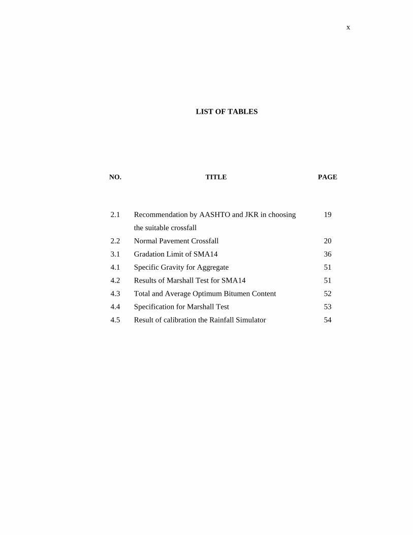
LIST OF TABLES
NO. TITLE
PAGE
2.1
2.2
3.1
4.1
4.2
4.3
4.4
4.5
Recommendation by AASHTO and JKR in choosing
the suitable crossfall
Normal Pavement Crossfall
Gradation Limit of SMA14
Specific Gravity for Aggregate
Results of Marshall Test for SMA14
Total and Average Optimum Bitumen Content
Specification for Marshall Test
Result of calibration the Rainfall Simulator
19
20
36
51
51
52
53
54

xi
LIST OF FIGURES
NO. TITLE
PAGE
1.1
2.1
2.2
2.3
2.4
2.5
2.6
3.1
3.2
3.3
3.4
3.5
3.6
3.7
3.8
3.9
3.10
3.11
3.12
3.13
3.14
3.15
Comparison structure of SMA and DGA
Microtexture and Macrotexture
Hydroplaning Tire
Hydrologic Cycle
Typical two-lane highway with linear crossfall
Coarse layer
Trend of changes of Skid Resistance
Flowchart of study
Stockpile receive new aggregate from plant
Method for aggregate sampling
Mechanical Sieve Shaker
Flowchart of Marshall Test
Marshall Drop Hammer
Flow and Stability Test
Aggregate and Bitumen mix together under 170oC
Mixture is ready to laid
Steel Roller Compacter
Surface of SMA14 after compaction
Pavement Mix
Sand Patch Apparatus
Sand Patch Test on Road Surface
Portable Skid Resistance
3
9
15
18
20
22
28
33
35
35
37
39
40
40
41
42
43
43
44
46
47
48

xii
4.1
4.2
4.3
4.4
4.5
4.6
4.7
4.8
4.9
Area of sand after test
PTV value against percentage of crossfall
Water Film Thickness against percentage of
crossfall
PTV value against 0% of crossfall
PTV value against 2% of crossfall
PTV value against 4% of crossfall
PTV value against 6% of crossfall
PTV value against 8% of crossfall
PTV value against 10% of crossfall
53
57
57
59
59
60
60
61
61

xiii
LIST OF APPENDIX
APPENDIX TITLE
PAGE
1
2
3
4
5
6
7
8
9
Sieve Analysis Gradation
Sand Patch Test Result for SMA 14
Mass for Rainfall Simulator Mould
(SMA14)
Polished Stone Value
Pavement Crossfall
Calculation for Texture Depth
Pendulum Test Value
Water Film Thickness
Flowmeter of Runoff
68
69
70
72
73
75
77
80
81

1
CHAPTER I
INTRODUCTION
1.1 General
Skid resistance is the force developed when a tyre that is prevented from
rotating slides along the pavement surface (Meyer W.E and Reichert. J, 1990). More
commonly, skid resistance is thought of as a pavement property; it is the antonym of
slipperiness. It is in this sense that skid resistance is used in this study. It refers to the
influence which the road surface has on the magnitude of the maximum driving,
braking or side forces between tyre and road. Previous study indicates that pavement
texture is the controlling factor in the skid-resistance level of roadway surfaces
(Kareem. A, 2003).
Skid resistance has been observed to be first and foremost a function of the
micro and macro-roughness of the pavement surface. The mixture composition
determines the micro- and macroscopic geometric properties of the surface. The
surface that needs to considered the micro and macroscopic geometric properties is
wearing course. This is because, wearing course is the upper level of the road
(contact directly to the tyre). So, it is important for wearing course to provide

2
smooth, skidding resistant and imperfection free surface on which to construct the
wearing course. This study will focus only for wearing course.
SMA was known as a mixture as a surface course on any high profile, high
volume roadways where a skid resistant and durables surface is required (Rockliff.
D, 2000). This is because, SMA has a high proportion of coarse aggregate that
interlocks to form a stone on-stone skeleton to resist permanent deformation. The
stone skeleton is filled with a mastic of bitumen and filler to which fibres are added
to provide adequate stability of bitumen and to prevent drainage of binder during
transport and placement.
Typical SMA composition consists of 70-80% coarse aggregate, 8-12% filler,
6.0-7.0% binder, and 0.3 per cent fibre. The high proportion of coarse aggregate
cause rough surface and give good resist for skidding (Cenek P.D, 2002). Material
initially exposed at the surface of a SMA will be binder, filler and stabilising
additives together with some fine aggregate. With the negative texture of the material
surface aggregates will play an important part in determining early life skid
resistance (Rockliff. D, 2000).
Meanwhile, a dense graded asphalt concrete gives a smooth and low texture
because of low macro-texture and consequently poor wet skidding resistance. SMA
mix design produces a generally flat surface which together with negative texture
provides a quieter surface than hot rolled asphalt and surface dressing systems and
has been responsible for its popularity with the general public. A further unexpected
benefit from the use of SMA was a reduction in spray from traffic.
The rut resistance capacity of SMA stems from a coarse stone skeleton
providing more stone-on-stone contact than with conventional dense graded asphalt
(DGA) mixes (refer Fig. 1.1). Improved binder durability is a result of higher
bitumen content, a thicker bitumen film and, lower air voids content. This high
bitumen content also improves of flexibility. Addition of a small quantity of cellulose
or mineral fibre prevents drainage of bitumen during transport and placement.

3
Figure 1.1: Comparison Side View of SMA and DGA
(Austroads Technical Note 16: Stone Mastic Asphalt, 2004)
1.2 Problem Statement
Rain is the most frequently encountered weather hazard on the roads.
Previous international road safety investigations have demonstrated that road
accidents increase in wet weather (Codling, 1974). In 1999, almost 17.6 % of all
accidents on the motorways in England and Wales occurred when it was raining. The
presence of water has a lubricating effect on a wet road (I. Becchi, 2000) and
reducing the road friction.
The relationship between road friction and road safety has been the object of
numerous studies. Giles and Sabey (1959) conducted a study on the relationship
between skid resistance measured with SN40 and accident rates. SN40 values in 120
sites where crashes had occurred due to skidding were compared with 100 randomly
selected control sites of similar characteristics and traffic volumes. The study
concluded that the risk of skidding crashes is extremely low when the SN40 value is
greater than 65 and that it increases rapidly for SN40 values below 50.
One major factor contributes to road accident is skidding as there is
connection between vehicle tyre and pavement. Skidding can happen on any
occasions but the worst skidding ever happen is during wet pavement condition

4
during rainy day. Problems of safety are closely linked to the state of the wearing
course. It can be minimized by the preservation of a good skid resistant on wearing
course. This study is focused on Stone Mastic Asphalt (SMA) only. The objective of
the study is to check how SMA perform in wet condition in term of skidding. The
study will test for various condition to find the most effective design for certain
rainfall intensity. Then, the comparison between ACW will be made to choose the
best skid resist amongst them.
1.3 Objective of Study
The objectives of this study are:
1. To measure skid performance of SMA under various conditions which is
different rainfall intensity and different crossfall percentage.
2. To compare the skidding performance of AC14 from previous study.
1.4 Scope of Study
This study will focused on Stone Mastic Asphalt. Crushed aggregates from
Malaysian Rock Product (MRP) quarry and bitumen PG 76 was used for the design
mix. Rainfall Simulator will used to simulate various type of rainfall on pavement.
Bitumen PG 76 will used for the design mix. Skidding characteristics will
determined by using Portable Skid Tester. JKR Specification are used as guide in this
study.

5
1.5 Importance of Study
The importance of this study is to determine the skidding characteristic of
SMA and do a comparison with DGA from previous study, which is the best to resist
the skidding during rainfall. This study also can be highlighted as a proposal to JKR
and local authorities in providing a new idea and concept towards the road
development in Malaysia.


![Research Articles - einspem.upm.edu.myeinspem.upm.edu.my/mathdigest/pdf/Magazine [Full] (Revised) 14.2.2018 (1).pdf · Sebarang pertanyaan atau kiriman artikel bolehlah dihantar kepada](https://img.pdfslide.us/doc/110x75/5d49170d88c9932f1f8b4cf3/research-articles-full-revised-1422018-1pdf-sebarang-pertanyaan-atau.jpg)