Embed Size (px)
Citation preview
CHARACTERISTIC MODEANALYSIS OF ANTENNA
1Sundaramoorthy A, 2John Wiselin,3Sreeja B S, 3Manikandan E,
3Roobini A1Research scholar,
Bharath University,Chennai, India
2Department of EEE,Vidhya Institute of Science and Technology,
Trivandrum, India3Department of ECE,
SSN College of Engineering,Chennai, India ,
May 24, 2018
Abstract
The main objective is to design different types of an-tenna with the desired radiation characteristics using themost effective design methods. It is used to obtain numeri-cal approach for antenna design and predicting radiating be-haviour of antenna by analysis of characteristic modes. Thetheory of characteristics mode is used to synthesize desiredcurrent distribution and radiating behavior of an antenna.The surface current distribution of different modes of an-tenna identifies the optimum feeding point for the designedantenna. The designed antenna may operate at multiplestandards so it may provide multiband or broadband oper-ation. It may be facilitate orthogonal radiation patterns at
1
International Journal of Pure and Applied MathematicsVolume 118 No. 24 2018ISSN: 1314-3395 (on-line version)url: http://www.acadpubl.eu/hub/Special Issue http://www.acadpubl.eu/hub/
a given frequency of multiple characteristic modes, whichprovide effective multiple input multiple output (MIMO)antennas.
Key Words:Theory of characteristic modes (TCM),Modal analysis, microstrip antenna, reflection coefficient,current distribution, radiation pattern.
1 Introduction
At present antenna design is essentially utilized on commercial ap-plications, especially cellular telephony systems and wireless sys-tems. The proposing new antennas are mainly devoted to describethe antenna geometry and its radiating behavior, while the de-sign procedure does not match the requirement and considerations,therefore the problems have to limit. Their problem is that thephysical accuracy is less, so the operating principles of the antennaare mislaid. The theory of characteristic modes (TCM) gives thenumber of current distribution and radiation pattern with respectto the different modes of frequency. The theory of characteristicmodes was first introduced by Garbacz [1] and later developed byHarrington and Mautz [2]. A procedure for conducting bodies ofarbitrary shape is developed [3]. Then the theory of character-istic modes is revisited for modern applications designed antenna[4].The modal analysis is proposed for multiple input multiple out-put (MIMO) applications [5-7]. Using this technique, both multi-band resonance and bandwidth is achieved [8]. This analysis isalso used for performance improvement of circularly polarized slot-ted patch antenna [9].Characteristic mode analysis (CMA) can beused to optimize the shape of antenna, to improve the antennatopology, decide on the antenna placement and synthesize a desiredantenna pattern for ultra wideband (UWB) transverse electromag-netic (TEM) horn and long term evolution (LTE) antenna usingFEKO [10]. The analysis of eigen current distribution gives newfeeding techniques. This technique will be of help to design com-pact ultra wideband antenna for chip integrating transceivers [11].The characteristic mode is equivalent to the method of moments(MoM) equations using the singular value decomposition and laterby its special case of spectral decomposition of matrix [12]. A newmethod of tracking procedures is introduced for theory of charac-
2
International Journal of Pure and Applied Mathematics Special Issue
teristic mode [13]. The MoM antenna is simulated with MATLABusing Rao-Wilton-Glisson (RWG) basis functions [14] and [15]. Themodal methods are also used to design complicated shapes like frac-tal patch antenna [16]. The effects of ground plane size, effects ofslot on the notched frequency characteristics and effects of minia-turization of monopole antenna is analyzed with the help of differentmodes of antenna [17].
The rest of the portion is organized as follows: Section II brieflyreviews the theory of characteristic mode and flow chart of TCM.In Section III, IV and V, the design of antenna, reflection coef-ficient, current distribution and radiation pattern of the differentmodes of rectangular, circular and hexagonal shape of antennas areexplained. Finally, some conclusions are given in Section VI.
2 THEORY OF CHARACTERISTIC MODES
The theory of characteristic modes (TCM) gives the number of cur-rent distribution and radiation pattern with respect to the differentmodes of frequency. The current distribution which is dependentupon eigen value and eigen vector. The mathematical formulationof characteristic modes that relates the current on conducting bodyas explained in [2],
[L(J)Ei]tan = 0 (1)
where tan denotes the tangential components on the surface S.The operator L in (1) is linear and it is defined by
L(J) = jωA(J) + ∆Φ(J) (2)
where A (J) and Φ (J) are vector and scalar potentials respec-tively. Physically, the term L (J) can be considered as the electricintensity at any point in space. This means that the operator L in(1) has the dimension of impedance:
Z(J) = [L(J)]tan (3)
As drawn from [1], the impedance operator Z is complex, andit can be written as,
Z(J) = R(J) + jX(J) (4)
3
International Journal of Pure and Applied Mathematics Special Issue
The Characteristic current modes are obtained from the eigenvalue linear equation which is given as
X−−→(Jn) = λnR
−−→(Jn) (5)
where R and X are Real and imaginary parts of impedance
operator Z=R+jX, λn is eigen value,−−→(Jn)is eigen function. It is
defined as the real currents on the surface of a conducting bodythat depends on shape and size. Thus design of antenna usingtheory of characteristic modes can be performed in way of:
• Characteristic current and associated characteristic fields arecalculated.
• By the eigen values, determine the resonance frequency of themodes.
• The shape and size is modified until the desired frequency isobtained.
• At last, studying the current distribution of modes and obtainspecific radiating field.
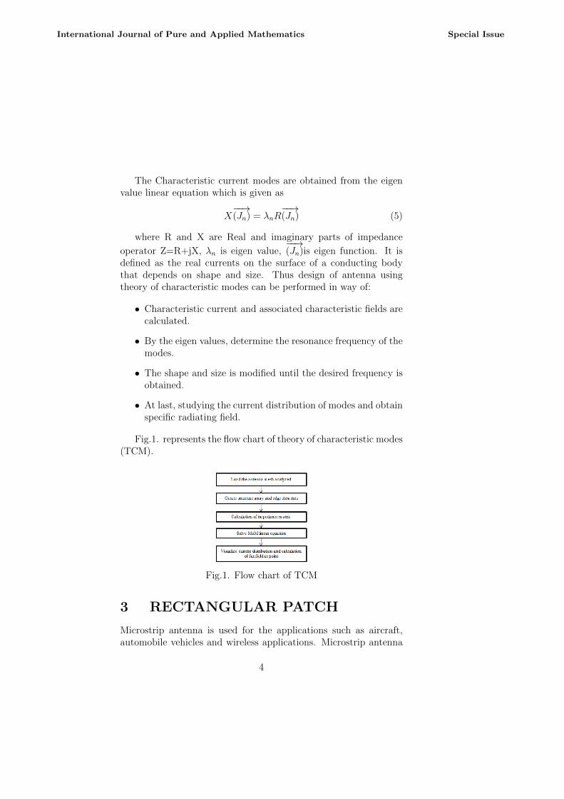
Fig.1. represents the flow chart of theory of characteristic modes(TCM).
Fig.1. Flow chart of TCM
3 RECTANGULAR PATCH
Microstrip antenna is used for the applications such as aircraft,automobile vehicles and wireless applications. Microstrip antenna
4
International Journal of Pure and Applied Mathematics Special Issue
consists of dielectric substrate, a radiating patch on one side anda ground plane on the other side. Microstrip antennas are alsoreferred to as patch antennas. The frequency of operation of thepatch antenna is determined by the length L. The width W of themicrostrip antenna controls the impedance on antenna feed. Theradiation in microstrip patch antenna is along the width and notalong the length of the patch. The electric field is zero at the middleof the patch, maximum at one side, and minimum on the oppositeside.
A. Design of Rectangular patchThe rectangular patch is designed for 2.4 GHZ. The dimension
of the rectangular patch depends on the length and width of thepatch. The width of the microstrip patch antenna controls theimpedance across the input. Larger width can also increase thebandwidth. Fig.1. illustrates the geometry of rectangular patch.Table I represents the dimensions of rectangular patch. The designcalculation is given as follows:
Frequency, f = 2.4 GHzPermittivity of FR4 substrate, εr= 4.3Height of FR4 substrate, h=1.6mma)WidthofthePatch,
W =c
2f√
εr+12
= 3 ∗ 1011 ∗ /4.8 ∗ 109
Width of the Patch,W = 38.39mm (6)
b) Length of the Patch, L= Leff − 2∆L Wavelength,
λ =c
f=
3 ∗ 1011
2.4 ∗ 109
= 125mmEffective dielectric constant, εeff
=εr + 1
2+εr − 1
2[1 + 12h/w]1/2
=2.65+1.65(0.8164)
5
International Journal of Pure and Applied Mathematics Special Issue
=3.99706Length Extension, ∆ L
= 0.412h(εeff+0.3)(
wh
+ 0.264)
(εeff−0.264)(wh
+ 0.8)
= 0.7412mmEffective length, Leff =
c
2f√εr
= 31.2614mm
Length of the patch, L = Leff − 2∆ LL=31.2614 - 2(0.7412)
Length of the patch, L=29.779 mm (7)
c) Feed length =λ
4√εr
= 31.25/√
4.3
Feed length = 15mm (8)
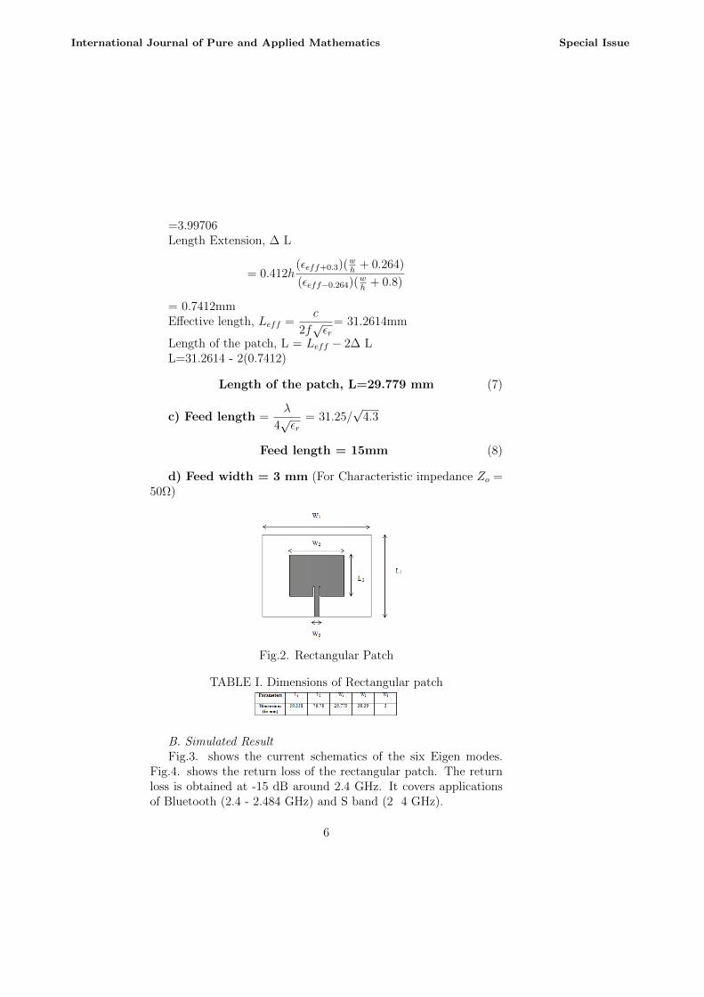
d) Feed width = 3 mm (For Characteristic impedance Zo =50Ω)
Fig.2. Rectangular Patch
TABLE I. Dimensions of Rectangular patch
B. Simulated ResultFig.3. shows the current schematics of the six Eigen modes.
Fig.4. shows the return loss of the rectangular patch. The returnloss is obtained at -15 dB around 2.4 GHz. It covers applicationsof Bluetooth (2.4 - 2.484 GHz) and S band (2 4 GHz).
6
International Journal of Pure and Applied Mathematics Special Issue
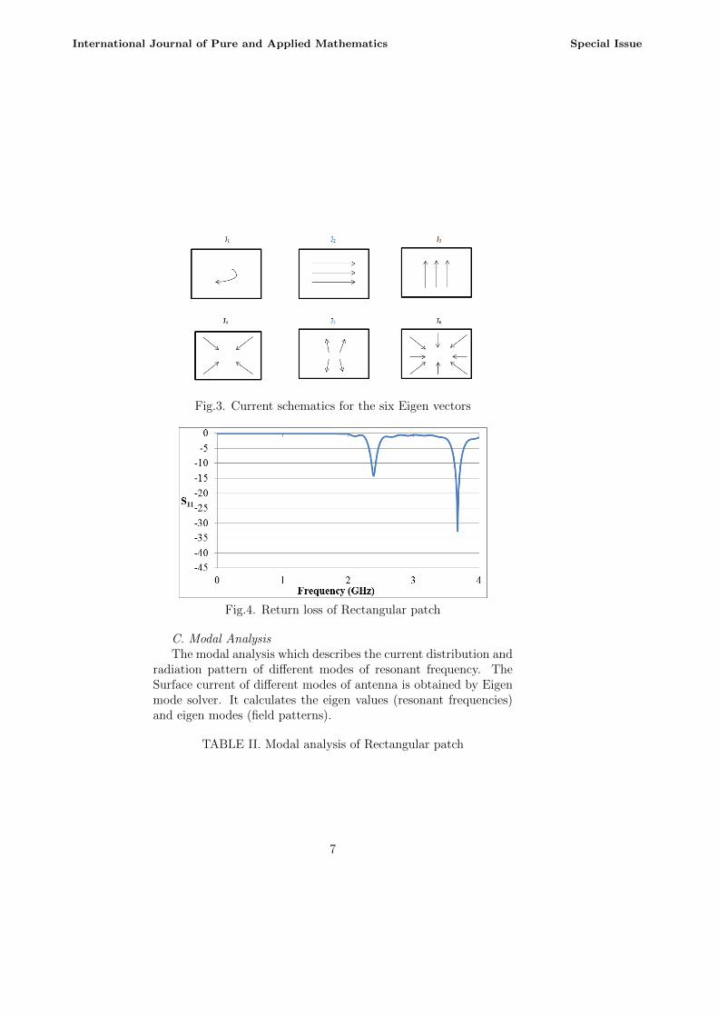
Fig.3. Current schematics for the six Eigen vectors
Fig.4. Return loss of Rectangular patch
C. Modal AnalysisThe modal analysis which describes the current distribution and
radiation pattern of different modes of resonant frequency. TheSurface current of different modes of antenna is obtained by Eigenmode solver. It calculates the eigen values (resonant frequencies)and eigen modes (field patterns).
TABLE II. Modal analysis of Rectangular patch
7
International Journal of Pure and Applied Mathematics Special Issue
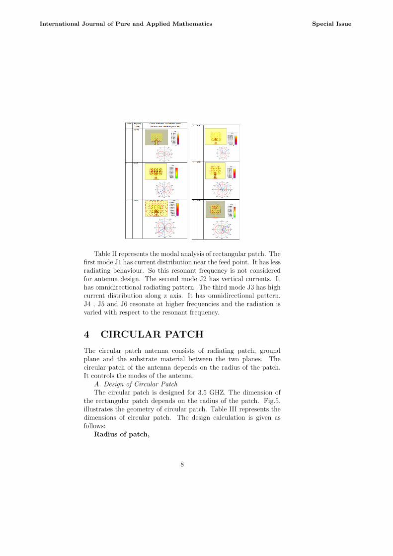
Table II represents the modal analysis of rectangular patch. Thefirst mode J1 has current distribution near the feed point. It has lessradiating behaviour. So this resonant frequency is not consideredfor antenna design. The second mode J2 has vertical currents. Ithas omnidirectional radiating pattern. The third mode J3 has highcurrent distribution along z axis. It has omnidirectional pattern.J4 , J5 and J6 resonate at higher frequencies and the radiation isvaried with respect to the resonant frequency.
4 CIRCULAR PATCH
The circular patch antenna consists of radiating patch, groundplane and the substrate material between the two planes. Thecircular patch of the antenna depends on the radius of the patch.It controls the modes of the antenna.
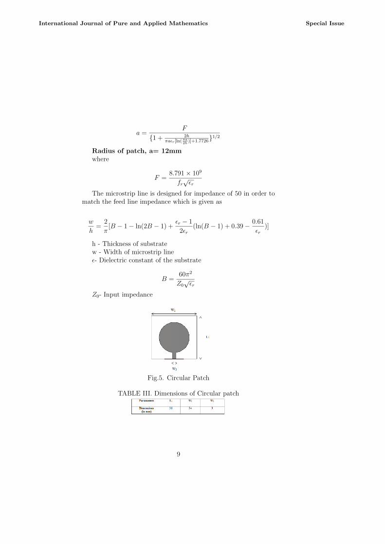
A. Design of Circular PatchThe circular patch is designed for 3.5 GHZ. The dimension of
the rectangular patch depends on the radius of the patch. Fig.5.illustrates the geometry of circular patch. Table III represents thedimensions of circular patch. The design calculation is given asfollows:
Radius of patch,
8
International Journal of Pure and Applied Mathematics Special Issue
a =F
1 + 2hπaεr[ln(
πa2h
)]+1.77261/2
Radius of patch, a= 12mmwhere
F =8.791× 10⁹
fr√εr
The microstrip line is designed for impedance of 50 in order tomatch the feed line impedance which is given as
w
h=
2
π[B − 1− ln(2B − 1) +
εr − 1
2εr(ln(B − 1) + 0.39− 0.61
εr)]
h - Thickness of substratew - Width of microstrip lineε- Dielectric constant of the substrate
B =60π2
Z0√εr
Z0- Input impedance
Fig.5. Circular Patch
TABLE III. Dimensions of Circular patch
9
International Journal of Pure and Applied Mathematics Special Issue
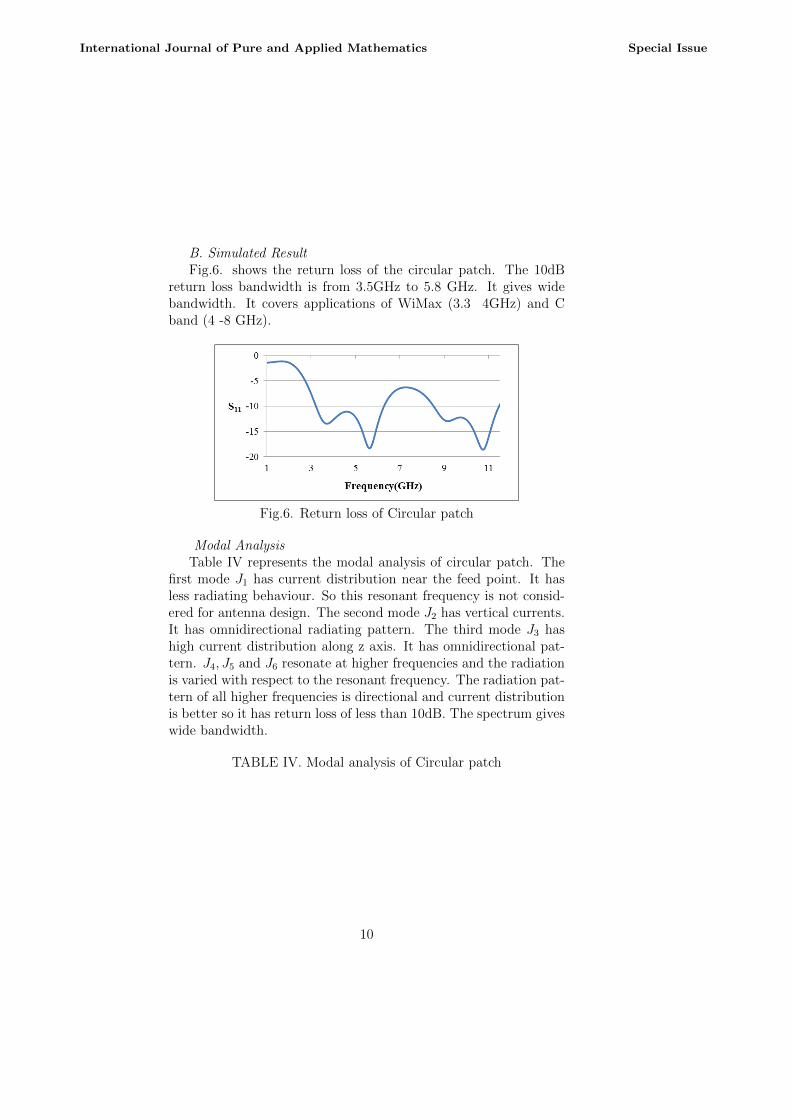
B. Simulated ResultFig.6. shows the return loss of the circular patch. The 10dB
return loss bandwidth is from 3.5GHz to 5.8 GHz. It gives widebandwidth. It covers applications of WiMax (3.3 4GHz) and Cband (4 -8 GHz).
Fig.6. Return loss of Circular patch
Modal AnalysisTable IV represents the modal analysis of circular patch. The
first mode J1 has current distribution near the feed point. It hasless radiating behaviour. So this resonant frequency is not consid-ered for antenna design. The second mode J2 has vertical currents.It has omnidirectional radiating pattern. The third mode J3 hashigh current distribution along z axis. It has omnidirectional pat-tern. J4, J5 and J6 resonate at higher frequencies and the radiationis varied with respect to the resonant frequency. The radiation pat-tern of all higher frequencies is directional and current distributionis better so it has return loss of less than 10dB. The spectrum giveswide bandwidth.
TABLE IV. Modal analysis of Circular patch
10
International Journal of Pure and Applied Mathematics Special Issue
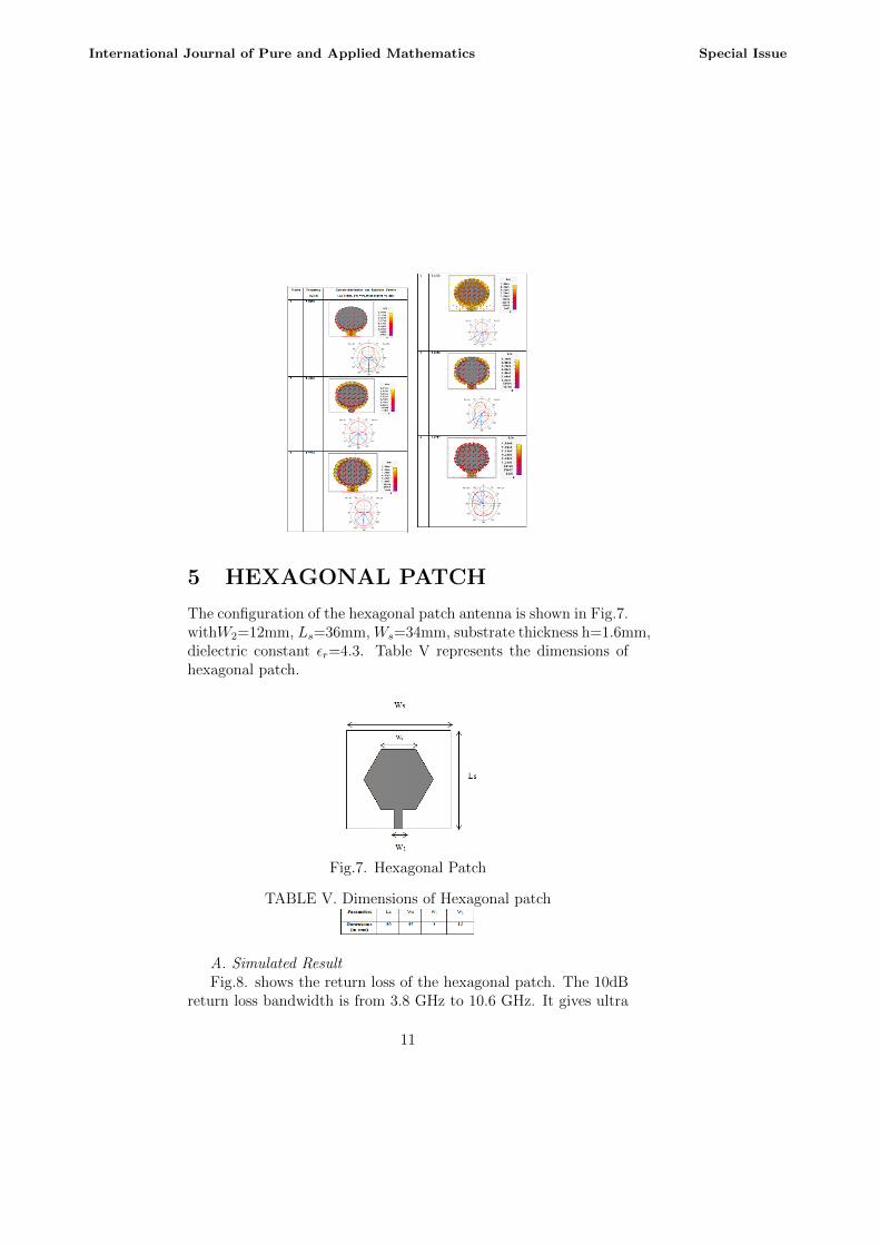
5 HEXAGONAL PATCH
The configuration of the hexagonal patch antenna is shown in Fig.7.withW2=12mm, Ls=36mm, Ws=34mm, substrate thickness h=1.6mm,dielectric constant εr=4.3. Table V represents the dimensions ofhexagonal patch.
Fig.7. Hexagonal Patch
TABLE V. Dimensions of Hexagonal patch
A. Simulated ResultFig.8. shows the return loss of the hexagonal patch. The 10dB
return loss bandwidth is from 3.8 GHz to 10.6 GHz. It gives ultra
11
International Journal of Pure and Applied Mathematics Special Issue
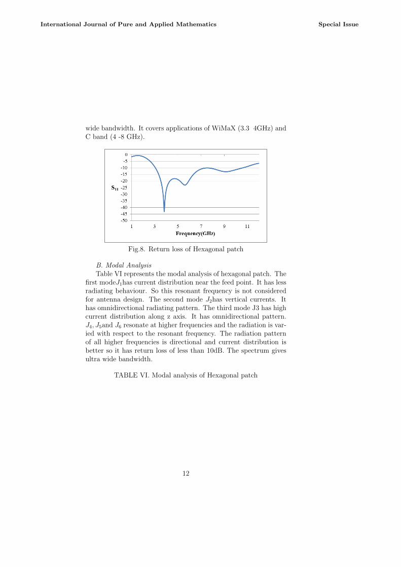
wide bandwidth. It covers applications of WiMaX (3.3 4GHz) andC band (4 -8 GHz).
Fig.8. Return loss of Hexagonal patch
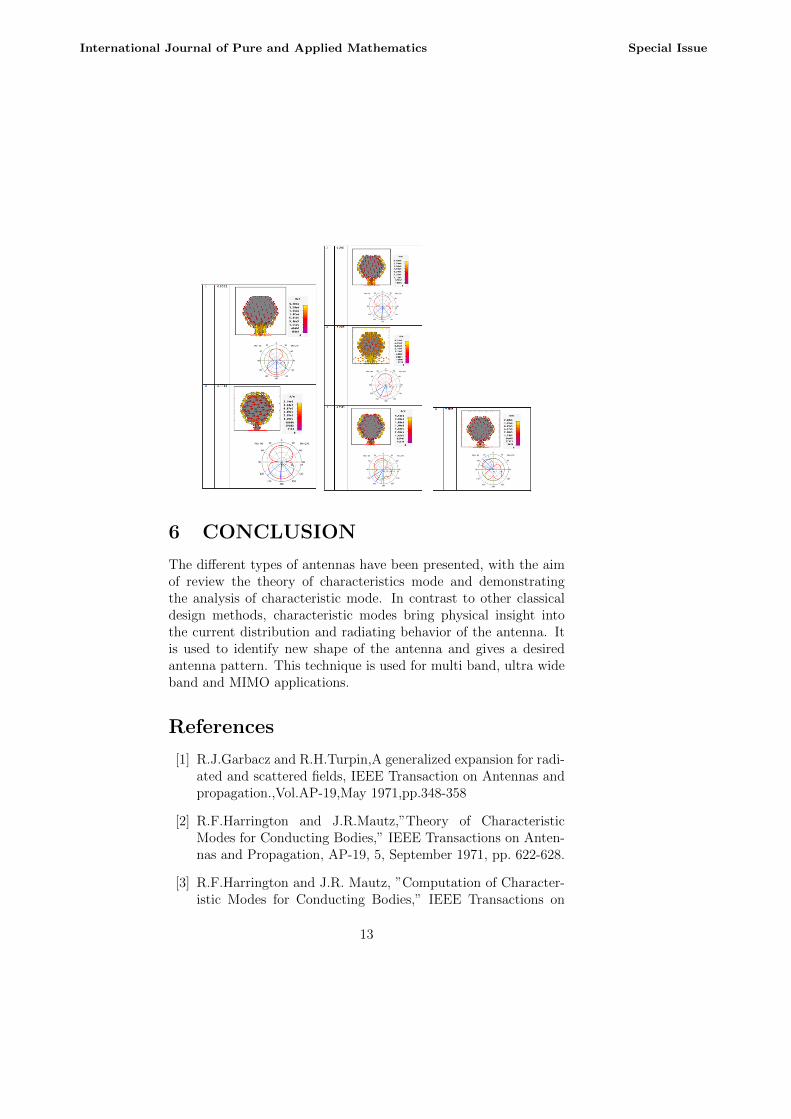
B. Modal AnalysisTable VI represents the modal analysis of hexagonal patch. The
first modeJ1has current distribution near the feed point. It has lessradiating behaviour. So this resonant frequency is not consideredfor antenna design. The second mode J2has vertical currents. Ithas omnidirectional radiating pattern. The third mode J3 has highcurrent distribution along z axis. It has omnidirectional pattern.J4, J5and J6 resonate at higher frequencies and the radiation is var-ied with respect to the resonant frequency. The radiation patternof all higher frequencies is directional and current distribution isbetter so it has return loss of less than 10dB. The spectrum givesultra wide bandwidth.
TABLE VI. Modal analysis of Hexagonal patch
12
International Journal of Pure and Applied Mathematics Special Issue
6 CONCLUSION
The different types of antennas have been presented, with the aimof review the theory of characteristics mode and demonstratingthe analysis of characteristic mode. In contrast to other classicaldesign methods, characteristic modes bring physical insight intothe current distribution and radiating behavior of the antenna. Itis used to identify new shape of the antenna and gives a desiredantenna pattern. This technique is used for multi band, ultra wideband and MIMO applications.
References
[1] R.J.Garbacz and R.H.Turpin,A generalized expansion for radi-ated and scattered fields, IEEE Transaction on Antennas andpropagation.,Vol.AP-19,May 1971,pp.348-358
[2] R.F.Harrington and J.R.Mautz,”Theory of CharacteristicModes for Conducting Bodies,” IEEE Transactions on Anten-nas and Propagation, AP-19, 5, September 1971, pp. 622-628.
[3] R.F.Harrington and J.R. Mautz, ”Computation of Character-istic Modes for Conducting Bodies,” IEEE Transactions on
13
International Journal of Pure and Applied Mathematics Special Issue
Antennas and Propagation, AP-19, 5, September 1971, pp.629-639.
[4] Marta Cabedo Fabres, Eva Antonino-Daviu, Alejandro ValeroNogueira and Miguel Ferrando Bataller,The theory of charac-teristic modes revisited: A contribution to the design of anten-nas for modern applications, IEEE Antennas and PropagationMagazine, Vol. 49, No. 5, pp.52,68 , October 2007.
[5] Ali Araghi and Gholamreza Dadashzadeh, Oriented design ofan antenna for MIMO applications using theory of character-istic modes, IEEE Antennas And Wireless Propagation, Vol.11, pp.1040,1043, 2012.
[6] Hui Li, Yi Tan, Buon Kiong Lau, Zhinong Ying and Sailing He,Characteristic mode based trade off analysis of antenna chassisiinteractions for multiple antenna terminals,IEEE TransactionsOn Antennas And Propagation, Vol. 60, No. 2, pp.490,502,February 2012.
[7] Martens, R.; Manteuffel, D., ”Systematic design method of amobile multiple antenna system using the theory of character-istic modes,” in Microwaves, Antennas & Propagation, IET ,vol.8, no.12, pp.887-893, Sept. 16 2014
[8] Zachary Miers,Hui Li and Buon Kiong Lau,Design ofbandwidth-enhanced and multiband MIMO antennas usingcharacteristic modes, IEEE Antennas And Wireless Propaga-tion, Vol. 12,No.2, pp.1696,1699, 2013.
[9] Y. Chen and C.-F. Wang, Characteristic-mode-based improve-ment of circularly polarized U-slot and E-shaped patch an-tennas,IEEE Antennas Wireless Propag. Lett, Vol. 11, pp.14741477, Dec. 2012.
[10] Martin Vogel, Gopinath Gampala, Daniel Ludick, UlrichJakobus and C. J. Reddy, Characteristics mode analysis:putting physics back into simulation ,IEEE Antennas andPropagation Magazine, Vol. 57, No. 2, pp.307,317, April 2015.
[11] Ahme Toaha Mobashsher and Amin Abbosh, Utilizing Sym-metry of Planar Ultrawideband Antennas for Size Reduction
14
International Journal of Pure and Applied Mathematics Special Issue
and Enhanced Performance, IEEE Antennas and PropagationMagazine, Vol. 57, No. 2, pp.153,156 April 2015.
[12] Pavel Hazdra, Pavel Hamouz, On The Modal SuperpositionLying Under The MoM Matrix Equations., Radioengineering,Vol. 17, No. 3, September 2008.
[13] M. Capek, P. Hazdra, P. Hamouz, and J. Eichler, A methodfor tracking characteristic numbers and vectors, Progr. Elec-tromagn . Res. B,vol. 33, pp. 115134, 2011.
[14] Makarov, S., ”MoM antenna simulations, with Matlab: RWGbasis functions,” IEEE Antennas and Propagation Magazine,IEEE , vol.43, no.5, pp.100-107, Oct 2001
[15] Capek, M.; Hamouz, P.; Hazdra, P.; Eichler, J., ”Implemen-tation of the Theory of Characteristic Modes in MATLAB,”IEEE Antennas and Propagation Magazine, IEEE , vol.55,no.2, pp.176-189, April 2013
[16] J. Eichler, P. Hazdra, M. Capek, T. Korinek, and P. Hamouz,Design of a dual-band orthogonally polarized L-probe-fed frac-tal patch antenna using modal methods, IEEE Antennas Wire-less Propag. Lett., vol. 10, pp. 13891392, Dec. 2011.
[17] W. Wu and Y. P. Zhang, Analysis of ultra-wideband printedplanar quasi-monopole antennas using the theory of character-istic modes, IEEE Antennas Propag. Mag., vol. 52, no. 6, pp.6777, Dec. 2010
15
International Journal of Pure and Applied Mathematics Special Issue