Embed Size (px)
Citation preview

REGISTRO BRASILEIRO Rules for the Construction and Classification of ships DIVING SUPPORT VESSELS - Title 48
DE NAVIOS E AERONAVES Identified by their Missions NAVAL ARCHITECTURE - Section 1
RGMM14EN CHAPTERS - A, B, E and H
1-1 RULES 2014
PART II RULES FOR THE CONSTRUCTION
AND CLASSIFICATION OF VESSELS
IDENTIFIED BY THEIR MISSIONS
TITLE 48 DIVING SUPPORT VESSELS
SECTION 1 NAVAL ARCHITECTURE
CHAPTERS
A APPROACH
B DOCUMENTS, REGULATIONS AND
STANDARDS
C NAVIGATIONAL ENVIRONMENT
– See Part II, Title 11, Section 1
D ACTIVITIES / SERVICES
– See Part II, Title 11, Section 1
E CONFIGURATIONS
F DIMENSIONS AND HULL SHAPE
– See Part II, Title 11, Section 1
G CAPACITIES AND SUBDIVISION
– See Part II, Title 11, Section 1
H CONDITIONS OF LOADING,
BUOANCY AND STABILITY
I PROPULSION PERFORMANCE
– See Part II, Title 11, Section 1
T INSPECTIONS AND TESTS
– See Part II, Title 11, Section 1

REGISTRO BRASILEIRO Rules for the Construction and Classification of ships DIVING SUPPORT VESSELS - Title 48
DE NAVIOS E AERONAVES Identified by their Missions NAVAL ARCHITECTURE - Section 1
RGMM14EN CHAPTERS - A, B, E and H
1-2 RULES 2014

REGISTRO BRASILEIRO Rules for the Construction and Classification of ships DIVING SUPPORT VESSELS - Title 48
DE NAVIOS E AERONAVES Identified by their Missions NAVAL ARCHITECTURE - Section 1
RGMM14EN CHAPTERS - A, B, E and H
1-3 RULES 2014
CONTENTS
CHAPTER A .........................................................................5 APPROACH..........................................................................5
A1. APPLICATION ......................................................5 100. Scope ...................................................................5
A2. DEFINITIONS .......................................................5 100. Glossary of Terms and Abbreviations .................5
CHAPTER B .........................................................................9 DOCUMENTS, REGULATIONS AND STANDARDS ....9
B1. DOCUMENTS FOR RBNA ...................................9 100. Documents for reference .....................................9 200. Documents for approval .....................................9 300. Documents for the construction ..........................9
B2. REGULATIONS AND STANDARDS ...................9 100. National Administration .....................................9 200. Other regulations / guidelines ............................9
CHAPTER E .........................................................................9 CONFIGURATIONS ...........................................................9
E3. BASIC ARRANGEMENT .....................................9 100. Position keeping..................................................9 200. Diver’s accommodation ......................................9 300. Diver deployment and recovery ........................10 400. Diver support equipment and deck surface
hyperbaric chambers (DCH) ........................................10 500 Compressors .....................................................11 600. Gas bottles ........................................................11 700. Dive control position and stand-by divers’
position .........................................................................12 800. Clear deck space ...............................................12 900. Other arrangements ..........................................12
E4. WATER ON DECK ..............................................13 100. Water on deck ...................................................13
E5. SHALLOW DEPTH OPERATION
LIMITATIONS – A GUIDELINE ....................................13 100. Guidelines for shallow depth operation
limitations for vessels fitted with SPD-2 systems ..........13 CHAPTER H .......................................................................14 LOADING CONDITIONS, BUOYANCY AND
STABILITY.........................................................................14 H4. BUOYANCY, HULL SUBDIVISION .................14
100. General .............................................................14 200. Damage assumptions for offshore dive
supporting vessel s ........................................................14 300. Subdivision ........................................................15
H5. STABILITY ..........................................................15 100. Weight distribution ...........................................15 200. Free surface ......................................................15 300. Intact stability ..................................................15 100. Applicable regulations ......................................15 200. Damage stability criteria for offshore diving
support vessels with notation DSV ................................15 300. Assumptions for calculating damage stability ..16

REGISTRO BRASILEIRO Rules for the Construction and Classification of ships DIVING SUPPORT VESSELS - Title 48
DE NAVIOS E AERONAVES Identified by their Missions NAVAL ARCHITECTURE - Section 1
RGMM14EN CHAPTERS - A, B, E and H
1-4 RULES 2014
REGISTRO BRASILEIRO Rules for the Construction and Classification of ships DIVING SUPPORT VESSELS - Title 48
DE NAVIOS E AERONAVES Identified by their Missions NAVAL ARCHITECTURE - Section 1
RGMM14EN CHAPTERS - A, B, E and H
1-5 RULES 2014
CHAPTER A
APPROACH
CHPATER CONTENTS
A1. APPLICATION
A2. DEFINITIONS
A1. APPLICATION
100. Scope
101. The Title 48 of the Rules applies to all vessels in-
tended for inland or open sea navigation designed to give
support for shallow water operation class notation SDSV
and deep diving class notation DSV operations as defined in
Part I Title 01 Section 1, B3.326.
102. For the Class Notation DSV or SDSV to be assigned
to a vessel, it is mandatory that the Diving Support System is
certified according to the IMO Code of Safety for diving
systems adopted 23 November 1995 as res. A.831(19).).
Guidance
A diving support vessel, as the name suggests is a vessel that
is used for the objective of diving into oceans. Divers, who
dive into the middle of the seas as a part of professional
diving process, need proper diving support. This necessary
support is provided by such a dive support vessel.
The concept of a diving support vessel came into existence
four to five decades ago. From that time onwards, these
ships have been extremely important to the field of commer-
cial diving which forms a vital part of professional diving.
It has to be noted that professional diving means diving for
the prospect of construction, repairing and maintenance of
oil-rigs and other important offshore naval constructions.
Such support vessels are typically flat-based or flat-
bottomed because it makes the diving part easy for the di-
vers. Additionally it has to be noted that such ships are
equipped with a Dynamic Positioning System or an anchor
mooring positioning system in order to help the vessel used
for diving support stay steady on the water.
In the absence of the Dynamic Positioning System or anchor
mooring positioning system, what could happen is that the
ship could move away from the intended diving spot which
would cause complications to the diver.
Another important feature in vessels that enable diving sup-
port is the saturation diving system. The saturation diving
system enforces the presence of combination of certain im-
portant gases like helium and oxygen for the diver. Without
proper saturation diving system, as the diver has to go very
deep into the oceanic water, this could cause complications
like lack of air leading to suffocation.
To state it in simple terms, a diving support vessel can be
termed as a helper who helps trained professionals to take
care of the maintenance of the technological developments.
As a marine support system, a dive support vessel stands
completely unique and alone.
End of guidance
A2. DEFINITIONS
100. Glossary of Terms and Abbreviations
101. Blackout: Loss of all main electrical power to thrust-
ers or DP control system. Loss of electrical power that pre-
vents the DP control system operating is known as DP
Blackout.
102. BOP Blow-out preventer: Blackout prevention.
103. Capability plot A theoretical polar plot of the ves-
sel’s capability for particular conditions of wind, waves and
current from different directions. These can be determined
for different thruster combinations.

REGISTRO BRASILEIRO Rules for the Construction and Classification of ships DIVING SUPPORT VESSELS - Title 48
DE NAVIOS E AERONAVES Identified by their Missions NAVAL ARCHITECTURE - Section 1
RGMM14EN CHAPTERS - A, B, E and H
1-6 RULES 2014
Guidance
Example of a DP capability plot chart
End of guidance
104. CCTV Closed circuit television.
105. Controlled disconnection Release in a planned and
controlled manner of all physical connections linking the
vessels/units involved in two-vessel operations and their
physical separation.
106. Diving bell means a submersible compression cham-
ber, including its fitted equipment, for transfer of diving per-
sonnel under pressure between the work location and the
surface compression chamber. [IMO Diving Code]
a. Open diving bell means a submersible chamber
where the lower part is open and fitted with a grilled
floor, for the transportation of at least two divers
from the surface to the working site, fitted with a
communication system, emergency gas supply, air
bubble or artificial respiratory mixture for the breath-
ing of the divers without the use of masks/helmets
and scuttles to observe the external environment.
[NORMAM 15].
107 Hyperbaric chamber (CH):
A sealable diving chamber, closed bell or dry bell - Pres-
sure vessel specially designed for human occupation, in
which the occupants may be subjected to hyperbaric condi-
tions, and which is employed for decompressions of divers
as well as for the treatment of hyperbaric accidents [NOR-
MAM 15, Chapter 1].
Guidance
A hyperbaric chamber is a pressure vessel with hatches
large enough for people to enter and exit, and a compressed
breathing gas supply to control the internal air pressure.
Such chambers provide a supply of oxygen for the user, and
are usually called hyperbaric chambers whether used un-
derwater or at the water surface or on land to produce un-
derwater pressures.
However, some use submersible chamber to refer to those
used underwater and hyperbaric chamber for those used out
of water.
The IMO Diving Code designates hyperbaric chamber as a
“Surface compression chamber", a pressure vessel for hu-
man occupancy with means of controlling the pressure in-
side the chamber.
There are two related terms which reflect particular usages
rather than technically different types:
- Decompression chamber, a hyperbaric chamber used
by surface-supplied divers to make their surface de-
compression stops

REGISTRO BRASILEIRO Rules for the Construction and Classification of ships DIVING SUPPORT VESSELS - Title 48
DE NAVIOS E AERONAVES Identified by their Missions NAVAL ARCHITECTURE - Section 1
RGMM14EN CHAPTERS - A, B, E and H
1-7 RULES 2014
- Recompression chamber, a hyperbaric chamber used
to treat or prevent decompression sickness.
When used underwater there are two ways to prevent water
flooding in when the submersible hyperbaric chamber's
hatch is opened.
- The hatch could open into a moon pool chamber, and
then its internal pressure must first be equalised to
that of the moon pool chamber.
- More commonly the hatch opens into an underwater
airlock, in which case the main chamber's pressure
can stay constant, while it is the airlock pressure
which shifts. This common design is called a lock-
out chamber, and is used in submarines, submersi-
bles, and underwater habitats as well as diving
chambers.
End of guidance
108, Life chamber: Hyperbaric chamber employed in
saturated diving operations or in diving operations required
its occupation for more than twelve (12) hours. Its interior is
fitted with an infra-structure suitable for supplying the min-
imum habitability condition for the divers for the period of
occupation, such as: showers, sanitary installations, sleeping
quarters, environmental control, etc. [NORMAM 15, Chap-
ter 1].
109. DGPS GPS plus a differential correction supplied by
one or more receivers at a known fixed location, to increase
the accuracy of the position fix.
110. DP Dynamic positioning: automatic control of ves-
sel’s position and heading by the use of thrusters with re-
spect to one or more position references. May also be used
to mean dynamically positioned.
111. DP control location Permanently manned location(s)
onboard a DP vessel or unit where the DPO is able to moni-
tor the performance of the DP system and where the DPO is
able to interface with the DP system, intervening as neces-
sary.
112. DP downtime Position keeping instability, loss of
redundancy which would not warrant either a red or yellow
alert, however loss of confidence has resulted in a stand
down from operational status for investigation, rectifications,
trials etc.
113. DP incident Loss of automatic control, loss of posi-
tion or any incident which has resulted in or should have
resulted in a red alert.
114. DP near-miss Occurrence which has had a detri-
mental effect on DP performance, reliability or redundancy
but has not escalated into ‘DP incident’, ‘undesired event’ or
‘downtime’.
115. DP system All equipment that supports automatic
position keeping control.
116. DP undesired event Loss of position or other event
which is unexpected/uncontrolled and has resulted in or
should have resulted in a yellow alert.
117. DP vessel Dynamically positioned vessel.
118. DPO Operator of the DP control system.
119. DSV Class notation for diving support vessels for
water depths larger than 50 metres. See Part I, Title 01, Sec-
tion 1, B3.326, requiring hyperbaric evacuation systems.
120. Duplex DP DP control system with full redundancy
including smooth automatic changeover between the two DP
control systems.
121. ECR Engine Control Room.
122. EDS Emergency Disconnect Sequence.
123. Emergency disconnection Unscheduled rapid shut-
down and release of all physical connections to enable sepa-
ration of vessels/units.
a. ESD 1 Emergency shutdown and disconnect 1.
b. ESD 2 Emergency shutdown and disconnect 2.
124. FMEA Failure mode and effects analysis.
125. Footprint A graphic illustration of a set of real ob-
servations of a vessel’s DP station keeping ability in particu-
lar environmental conditions.
126. FPU / FPSO Floating production unit / Floating
production storage and offloading unit / .
127. GPS Global positioning system using satellites to
establish a vessel’s position, e.g. Navstar or GLONASS.
128. GPS relative Differential and relative position sys-
tem (note DGPS is used generally in this document but the
same principles apply both for dual DGPS as dual DARPS
or dual GPS).
129. Green status Normal operational status; adequate
DP equipment is on line to meet the required performance
within the declared safe working limits.
130. HAZID Hazard identification.
131. HAZOP Hazardous operation.
132. HPR Any hydroacoustic position reference system.
133. Hazardous areas are those locations in which an
explosive gas-air mixture is continuously present, or present
for long periods (zone O); in which an explosive gas-air

REGISTRO BRASILEIRO Rules for the Construction and Classification of ships DIVING SUPPORT VESSELS - Title 48
DE NAVIOS E AERONAVES Identified by their Missions NAVAL ARCHITECTURE - Section 1
RGMM14EN CHAPTERS - A, B, E and H
1-8 RULES 2014
mixture is likely to occur in normal operation (zone 1 ); in
which an explosive gas-air mixture it not likely to occur, and
if it does it will only exist for a short time (zone 2).
134. Hyperbaric evacuation system means the whole
plant and equipment necessary for the evacuation of divers
in saturation from a surface compression chamber to a place
where decompression can be carried out. The main compo-
nents of a hyperbaric evacuation system include the hyper-
baric evacuation unit, handling system and life-support sys-
tem.
135. Hyperbaric evacuation unit (HEU) means a unit
whereby divers under pressure can be safely evacuated from
a ship or floating structure to a place where decompression
can be carried out.
136. I/O Input/output.
137. Independent joystick A joystick that is independent
of the DP control system.
138. Limit alarms Selectable values for position and
heading excursions at which points an alarm will activate.
139. Loss of position Movement(s) of vessel and/or unit
from the intended or target position.
140. OIM Offshore Installation Manager.
141. Offshore diving support vessels: ships whose mis-
sion is to give support for diving operations in the proximity
of platforms (see A2.142 below). Reference is made to Part
II, Title 47 of the Rules.
Guidance
Offshore vessels are classified by the Brazilian Maritime
Authority as complying with the coastal navigation regula-
tions (DVC, visual distance from the shore) having, howev-
er, the 20 miles from shore boundary extended to 200 miles
from shore in areas inside Brazilian Jurisdictional Waters
inside the “Zona Economica Exclusiva” (Exclusive Eco-
nomical Zone).
End of guidance
142. Platform Any structure that is fixed relative to the
DP vessel.
143. Plough Towed unit generally used to bury cables.
144. Red alert DP emergency status: Position and/or
heading loss have happened or are inevitable.
145. Redundancy The ability of a component or system to
maintain or restore its function, when a single failure has
occurred. Redundancy can be achieved, for instance, by in-
stallation of multiple components, systems or alternate
means of performing a function.
146. Responder A transponder in which the interrogation
is by an electronic pulse sent down a cable. This is generally
fitted to an ROV and interrogated down the ROV’s umbili-
cal.
147. ROV Remotely operated vehicle that operates sub-
sea.
148. Safe working limits The environmental limits that a
vessel or company sets for safely working on DP taking into
account specified equipment failures and limitations im-
posed by the current worksite.
149. SDSV - Class notation for diving support vessels for
shallow water depths equal or less than 50 metres and time
of dive less than 12 hours. See Part I, Title 01, Section 1,
B3.326.
150. Shallow water A depth of water of 60 metres or less,
in which, depending upon the work being undertaken by the
DP vessel, further considerations may be necessary.
151. SIMOPS Simultaneous operations.
152. Thruster Any propulsion device used by the DP con-
trol system.
153. Transponder Device on the seabed that responds to
acoustic interrogation from the HPR on the vessel and gives
vessel relative position.
154. Trencher Subsea vehicle used for pipe or control
line burial.
155. Umbilical Connection carrying life support and
communication systems between a support vessel and a div-
ing bell, an ROV or similar device (also diver’s umbilical
between diver and bell).
156. UPS Uninterruptible power supply – unit to pro-
vide electricity continuously to DP control system in the
event of a blackout of the vessel’s main power.
157. Worst case failure The worst case failure of a DP
system is the failure that has been the basis of the design and
proved by the FMEA. This usually relates to a number of
thrusters and generators that can simultaneously fail and that
are used in consequence analysis.
158. Yellow alert Degraded DP status for which the DP
vessel has a pre-planned response to prepare for the risks
associated with a DP red alert.

REGISTRO BRASILEIRO Rules for the Construction and Classification of ships DIVING SUPPORT VESSELS - Title 48
DE NAVIOS E AERONAVES Identified by their Missions NAVAL ARCHITECTURE - Section 1
RGMM14EN CHAPTERS - A, B, E and H
1-9 RULES 2014
CHAPTER B
DOCUMENTS, REGULATIONS AND STANDARDS
CHAPTER CONTENTS
B1. DOCUMENTS FOR RBNA
B2. REGULATIONS
B3. TECHNICAL STANDARDS – See Title 11
B1. DOCUMENTS FOR RBNA
100. Documents for reference
– See Title 11
200. Documents for approval
201. In addition to the requirements of the Part II, Title 11,
Section 1 the following data and specifications of the diving
system installation is to be submitted for RBNA approval:
a. General arrangement showing the locations of the
diving support systems
b. Capacity data
c. Stability and Trim Booklet including intact and dam-
aged stability
300. Documents for the construction
- See Title 11
B2. REGULATIONS AND STANDARDS
100. National Administration
101. These rules include compliance with the requirements
of NORMAM 15 – DPC – Chapter 13 –“ Emprego de Em-
barcações de Posicionamento Dinâmico para Apoio às
Operações de Mergulho” (Use of dynamic positioning ships
for the support of diving operations).
200. Other regulations / guidelines
201. These rules are in compliance with the following regu-
lations / guidelines:
a. IMCA - IMCA M 103 Rev. 1 - Guidelines for the
Design and Operation of Dynamically Positioned
Vessels – Chapter 2 – Diving Support Vessels
b. IMCA M 175 – Guidance on operational communica-
tions: Part 1 – Bridge and dive control
c. OTH 90 336 – Offshore Technology Report – De-
partment of Energy – UK - 1991 – ISBN 011
413345 X
d. IMO Code of Safety for diving systems adopted 23
November 1995 as res. A.831(19).).
e. IMCA – MCA D 052 May 2013 – Guidance on Hy-
perbaric Evacuation Systems.
f. IMO.Resolution MSC.235(84) Guideline for the De-
sign and Construction of Supply Vessels
CHAPTER E
CONFIGURATIONS
CHAPTER CONTENTS
E1. ADEQUACY OF THE HULL – See Title 11
E3. BASIC ARRANGEMENT
E4. WATER ON DECK
E5. SHALLOW DEPTH OPERATION LIMITATIONS
E3. BASIC ARRANGEMENT
100. Position keeping
101. A Diving support vessel shall be able to keep its posi-
tion safely throughout the diving operations.
The position keeping may be achieved:
a. by a pattern of anchors around the ship, if in open
water;
b. by a combination of anchors and moorings to fixed
installations;
c. by a Dynamic Positioning (DP) system in compliance
with the requirements for DP-2 vessels in Part II, Ti-
tle 103, Section 8 of the Rules.
200. Diver’s accommodation
201. In addition to National and International Standards
for Habitability, adequate accommodation arrangements
should be provided for the divers not less than the minimum
below:
a. No more than two diving personnel should be ac-
commodated in one cabin;

REGISTRO BRASILEIRO Rules for the Construction and Classification of ships DIVING SUPPORT VESSELS - Title 48
DE NAVIOS E AERONAVES Identified by their Missions NAVAL ARCHITECTURE - Section 1
RGMM14EN CHAPTERS - A, B, E and H
1-10 RULES 2014
b. Diving supervisors should be allocated in single cab-
ins;
c. Cabins should be effectively ventilated and kept at
comfortable temperatures and levels of humidity;
d. Noise and vibration levels should be retained within
the National and International standards. Noise lev-
els are not to exceed 60 dB (A);
e. Washing and toilet facilities for divers should be pro-
vided in the vicinity of the diving station as well as in
accommodation areas. At least one shower and toilet
for every four diving personnel should be provided.
f. Stowage should be provided for diver’s clothing and
foul weather gear.
300. Diver deployment and recovery
301. The location for the deployment of divers should be
carefully selected to achieve optimum access to the work site
as well as minimum possible motion.
400. Diver support equipment and deck surface hyper-
baric chambers (DCH)
401. When preparing for the installation of equipment to
support air range diving operations, two main factors should
be considered:
a. Accessibility
b. Protection
402. Equipment not specifically required to be located on
deck should be positioned clear of this area.
403. Deck compression chambers must be mounted in the
immediate vicinity of the diver deployment position in such
a way that it is possible for divers in emergency to be
recompressed within 2 minutes of leaving the water.
404. Where possible DCH should be on the same deck as
the diver deployment position, but never more than one deck
above or below.
405 The number of hatches, doors and ladders should be
kept to a minimum and allow the passage of an incapacitated
diver
406. There should be sufficient space around DCH to en-
sure clear access for their operation, maintenance, and a 2
metre clearance in front of the access hatches to enable in-
jured divers to be manoeuvred into the DCH on stretchers.
407. DCH and their control panels should be protected
from the elements and from mechanical damage, and proper-
ly secured to avoid movement in heavy weather.
408. DCH should always be located clear of potential fire
hazard.
409. Diving systems and gas storage facilities are not to be
installed in machinery spaces that have machinery not asso-
ciated with the diving systems.
410. Diving systems are not to be installed in the vicinity
of exhaust / ventilation outlets from machinery spaces and
galleys.
411. It is recommended that pressure vessels for human
occupancy be arranged along the longitudinal (fore-aft) di-
rection of the vessel in order to minimize the rolling effect
on divers within them.
412. Where there are impressed current system anodes,
such system must be turned off during diving operations.
413. Requirements for the use of Hyperbaric Chambers:

REGISTRO BRASILEIRO Rules for the Construction and Classification of ships DIVING SUPPORT VESSELS - Title 48
DE NAVIOS E AERONAVES Identified by their Missions NAVAL ARCHITECTURE - Section 1
RGMM14EN CHAPTERS - A, B, E and H
1-11 RULES 2014
TABLE T.E3.413.1 – REQUIREMENTS FOR THE USE OF HYPERBARIC CHAMBERS
Diving characteristics Requirements for CH Class
notation
Depth of dive 50 metres or under
Maximum time of permanence 12 hours
Open or closed CH
Hyperbaric evacuation system not re-
quired
SDSV
Time of dive over 12 hours Closed CH with environmental tem-
perature and humidity control and
complete sanitary system including
bowl, shower and lavatory with hot
and cold water
SDSV
DSV
Depth of dive larger than 50 metres Closed CH with environmental tem-
perature and humidity control and
complete sanitary system including
bowl, shower and lavatory with hot
and cold w
Hypberbaric Evacuation System re-
quired
DSV
Offshore Diving Support Vessels Further to the above, offshore diving
support vessels, as defined in A2.141
above,having L ≥ 24 m, GT ≥ 500 and
notation DSV working in the proximi-
ty of platforms (see A2.142 above)
where there is a possibility of collision
during manoeuvres, damage should be
assumed to occur anywhere in the ves-
sel' s length between transverse water-
tight bulkheads.
OFFSHORE,
DSV
500 Compressors
501. Compressors should be mounted in positions which
ensure good access for maintenance and protection from the
elements.
502. They should be clear of accommodation and working
deck areas.
503. Air intakes should be so located as to avoid possible
contamination from funnel and exhaust fumes and from
spray.
504. Where two compressors are fitted their intakes should
be separate.
505. Carbon monoxide should be removed at the compres-
sor outlets to ensure the quality of air is up to the required
standards such as:
a. NORMAM 15 item 1209;
b. British BS4001 Part I.
506. An alarm should be positioned at the dive control
position to warn of low pressure.
507. Reserve capacity shall always be available to ensure
that divers can be safely recovered and decompressed.
508. Great care shall be taken to minimize the risk of fire
posed by fuel leaks and spills from diesel powered compres-
sors.
600. Gas bottles
601. Gas bottles should be located clear of fire hazards
and carefully protected from damage and movement induced
by vessel motion. Where stowed on deck, they are to be
effectively protected from weather (seas and heat) and me-
chanical damage.
602. They should be clearly marked.
603. Bottles containing oxygen or gases with oxygen con-
tent greater than 25% should be stored on an upper deck and
have a dedicated water deluge system.
604. Where gas bottles are stored in enclosed spaces, the
following requirements apply:
a. Boundaries of the enclosed space to other enclosed
spaces are to be gas tight;
b. Access doors are to open outwards;

REGISTRO BRASILEIRO Rules for the Construction and Classification of ships DIVING SUPPORT VESSELS - Title 48
DE NAVIOS E AERONAVES Identified by their Missions NAVAL ARCHITECTURE - Section 1
RGMM14EN CHAPTERS - A, B, E and H
1-12 RULES 2014
c. Outlet relief valves are to be led to the open deck
away from sources of ignition;
d. Enclosed spaces containing the breathing gas bottles
are to be fitted with ventilation providing at least
eight air changes per hour, independent of other ven-
tilation systems, and drawn from a non-hazardous ar-
ea. Ventilation system fans are to be of the non-
sparking type.
e. In case the gas mixture contains less than 18% of ox-
ygen by volume, the enclosed space is to be fitted
with oxygen analyzers, one monitoring the upper are-
as and the other the lower areas of the enclosed
space, fitted with audio-visual alarms.
700. Dive control position and stand-by divers’ position
701. The diver control position should be located in such a
position as to ensure good physical access to and visibility of
the working deck, diver deployment positions and DCH and,
in particular, protected from equipment having high noise
levels.
702. Closed circuit TV with and independent back-up may
be used to achieve the visibility requirements.
703. Breathing equipment with built-in communication
should be provided for the personnel required to continue
working in the Dive Control Position if the area becomes
smoke filled.
704. Positions should be allocated to stand-by divers
which provide protection from the elements, from noisy
equipment and allow sufficient space for stowage of umbili-
cals and divers’ equipment.
705. Stand-by divers’ position should ensure their speedy
and unrestricted deployment using the secondary means of
deployment whenever possible.
800. Clear deck space
801. The arrangement of the equipment should ensure that
sufficient clear deck space is available to enable the task to
be carried out without introducing risk to personnel or
equipment.
802. Clear walkways and escape routes should be unob-
structed and clearly marked on either side of the working
deck.
900. Other arrangements
901. Cable, pipes, hoses
a. All cables, pipes and hoses providing diving support
systems should be run in such a way and so protected
as to minimize the risk of damage.
b. Routing of cables and piping should avoid areas of
high physical activity
c. Long runs of flexible hoses for oxygen should always
be avoided as well as sharp bends in piping.
d. Proper securing arrangements should be fitted to
avoid movement
e. Suitable protection from mechanical damage should
be provided including the use, whenever possible, of
rigid rather than flexible hoses.
f. Deck and bulkhead penetrations are to be approved
by RBNA.
g. Electric junction boxes related to diving should be
insulated to IP 65 rating and installed in positions
which introduce minimum risk of damage.
902. Hot water machines
a. Hot water machines shall be sited in positions which
protect them from the elements and mechanical dam-
age and are clear of the working deck and accommo-
dation areas.
b. Hot water machines should have electrical heaters.
Diesel fired hot water heaters should only be used as
secondary back-up systems.
c. Diesel units should always be provided with effective
ventilation and precautions taken to detect and extin-
guish fires. Cofferdams or trays of sufficient capacity
should be provided around them to accommodate any
foreseeable spillage with large gravity drains to re-
move any spilt or burning fuel to a safe place.
903. ROV Operations
a. If ROV and diver operations are being carried out
simultaneously from the same vessel then the opera-
tional areas of each should be sufficiently separated
to ensure that diving operations are not jeopardised
and down-lines for the diving operations and position
references are not interfered with.
b. Hard wire communications and back up communica-
tions shall be maintained between the ROV Supervi-
sor and the Diving Supervisor whenever ROVs are
being operated.
c. Repeats of the ROV video monitor(s) should be pro-
vided in the Dive Control position.

REGISTRO BRASILEIRO Rules for the Construction and Classification of ships DIVING SUPPORT VESSELS - Title 48
DE NAVIOS E AERONAVES Identified by their Missions NAVAL ARCHITECTURE - Section 1
RGMM14EN CHAPTERS - A, B, E and H
1-13 RULES 2014
E4. WATER ON DECK
100. Water on deck
101. Non slip working surfaces shall be provided. Per-
sonnel protection equipment such as hard hats, boots, life
vests are to be available.
102. When calculating the freeboard, deck flooding as
well as the time for the divers to climb and enter the decom-
pression chambers is to be taken into account.
103. Appropriate means of efficient water exit from the
deck are to be provided.
Guidance
While a higher freeboard and bulwark will reduce the in-
gress of water on deck, the increased height will require
more difficult conditions for the divers to climb and reach
the compression chamber.
End of guidance
E5. SHALLOW DEPTH OPERATION LIMITA-
TIONS – A GUIDELINE
100. Guidelines for shallow depth operation limitations
for vessels fitted with SPD-2 systems
101. Vessel Draught
a. While the appropriate clearance the vessel needs be-
tween the seabed and the keel or lowest thruster is to
be determined by the master of the DP vessel taking
into account the weather forecast, heights of the tides,
vessel motion and the presence of subsea obstruc-
tions, design consideration should also be given to
the clearance that is required by the divers’ deploy-
ment device.
b. The above factors will determine the shallow water
limits of a SDSV with a SPD-2 positioning system.
102. Vessel Capability: the vessel’s capability plots may
not accurately give the limiting environmental conditions for
shallow water and operators should expect higher thruster
and generator loads than for the same wind speed in deeper
water and, as a consequence, termination of diving support
operations earlier than might otherwise have been expected.
For vessels with a consequence analysis warning, the re-
duced capability should automatically be taken into account.
103. Position References
a. The major difference between deep and shallow wa-
ter diving support operations is the distance the vessel
is able to move whilst maintaining seabed based posi-
tion references on line. This is further reduced if the
accuracy of the position references is poor.
b. Each of the vessel’s position references should pro-
vide position information accurate to ±2% of the wa-
ter depth. For example in 30m of water the infor-
mation provided by the reference systems should
have a standard deviation of ±0.6m.
c. There should always be at least three position refer-
ence systems on line of which one should be a radio
or surface position reference.
d. When working in water depths of less than 50m the
scope (radius of operation) of each of the three posi-
tion references should be equal to or greater than
30% of the water depth, and never less than 5m for
example water depth =30m, radius of operation 9m.
e. In general terms, the shallower the water depth the
smaller the scope for movement before seabed posi-
tion reference sensors need relocation. In particular:
e.1. the scope of vertical taut wires is greatly re-
duced depending on the height of the suspen-
sion point;
e.2. acoustics are more susceptible to interference
from the vessel;
e.3. the peak natural excursion of the vessel can
exceed the scope of a bottom position refer-
ence.
f. Surface reference systems, not being susceptible to
water depth, may offer greater reliability. These may,
however, have limitations, the acceptability of which
should be assessed.
g. The standard deviation of the vessel’s natural excur-
sions should not exceed one third of the scope of any
position reference.
h. Reference is made to IMCA D 010 – Diving opera-
tions from vessels operating in dynamically posi-
tioned mode.

REGISTRO BRASILEIRO Rules for the Construction and Classification of ships DIVING SUPPORT VESSELS - Title 48
DE NAVIOS E AERONAVES Identified by their Missions NAVAL ARCHITECTURE - Section 1
RGMM14EN CHAPTERS - A, B, E and H
1-14 RULES 2014
CHAPTER H
LOADING CONDITIONS, BUOYANCY AND STA-
BILITY
CHAPTER CONTENTS
H1. FREEBOARD
- See Title 11
H2. LIGHTSHIP WEIGHT
- See Title 11
H3. LOADING CONDITIONS
- See Title 11
H4. BUOYANCY, HULL SUBDIVISION
H5. STABILITY
H6. DAMAGED STABILITY
H4. BUOYANCY, HULL SUBDIVISION
[IMO Resolution MSC 235 (82)]
100. General
101. Taking into account, as initial conditions before
flooding, the standard loading conditions required by the
relevant provisions of Part B of the IMO IS Code and the
damage assumptions in Subchapter H4 the vessel should
comply with the damage stability criteria as specified in
Subchapter H6 below.
200. Damage assumptions for offshore dive supporting
vessel s
201. In offshore diving support vessels havng GT ≥ 500,
as defined in A2.141 above, for which the notation DSV has
been assigned, working in the proximity of platforms (see
A2.142 above) where there is a possibility of collision dur-
ing manoeuvres, damage should be assumed to occur any-
where in the vessel' s length between transverse watertight
bulkheads.
202. The assumed extent of damage should be as follows:
a. longitudinal extent:
a.1. for a vessel the keel of which is laid or which
is at a similar stage of construction before 22
November 2012
Guidance
A similar stage of construction means the stage at which:
i. construction identifiable with a specific ship begins;
and
ii. assembly of that ship has commenced comprising at
least 50 tonnes or one per cent of the estimat-
ed mass of all structural material, whichever
is less.
- with length (L) not greater than 43 m:
10% of L; and
- with length (L) greater than 43 m: 3 m
plus 3% of L;
iii. for a vessel the keel of which is laid or which is at a
similar stage of construction on or after
22 November 2012:
- with length (L) not greater than 43 m:
10% of L;
- with length (L) greater than 43 m and
less than 80 m: 3 m plus 3% of L; and
- with length (L) from 80 m to 100 m:
1/3L2/3;
End of guidance
b. transverse extent:
b.1. for a vessel the keel of which is laid or which
is at a similar stage of construction before 22
November 2012:
i. 760 mm measured inboard from the
side of the vessel perpendicularly to the
centreline at the level of the summer
load waterline;
b.2. for a vessel the keel of which is laid or which
is at a similar stage of construction on or after
22 November 2012:
i. with length (L) less than 80 m: 760
mm; and
ii. with length (L) from 80 m to 100 m:
B/20, but not less than 760 mm;
b.3. The transverse extent should be measured in-
board from the side of the vessel perpendicu-
larly to the centreline at the level of the sum-
mer load waterline; and
c. vertical extent:
c.1. from the underside of the cargo deck, or the
continuation thereof, for the full depth of the
vessel.
203. For a vessel the keel of which is laid or which is at a
similar stage of construction:

REGISTRO BRASILEIRO Rules for the Construction and Classification of ships DIVING SUPPORT VESSELS - Title 48
DE NAVIOS E AERONAVES Identified by their Missions NAVAL ARCHITECTURE - Section 1
RGMM14EN CHAPTERS - A, B, E and H
1-15 RULES 2014
a. before 22 November 2012:
a.1. A transverse watertight bulkhead extending
from the vessel's side to a distance inboard of
760 mm or more at the level of the summer
load line joining longitudinal watertight bulk-
heads may be considered as a transverse wa-
tertight bulkhead for the purpose of the dam-
age calculations.
b. on or after 22 November 2012:
c. For a vessel with length (L) less than 80 m, a trans-
verse watertight bulkhead extending from the vessel's
side to a distance inboard of 760 mm or more at the
level of the summer load line joining longitudinal wa-
tertight bulkheads may be considered as a transverse
watertight bulkhead for the purpose of the damage
calculations. For a vessel with length (L) from 80 m
to 100 m, a transverse watertight bulkhead extending
from the vessel's side to a distance inboard of B/20 or
more (but not less than 760 mm) at the level of the
summer load line joining longitudinal watertight
bulkheads may be considered as a transverse water-
tight bulkhead for the purpose of the damage calcula-
tions.
204. If pipes, ducts or tunnels are situated within the as-
sumed extent of damage, arrangements should be made to
ensure that progressive flooding cannot thereby extend to
compartments other than those assumed to be floodable for
each case of damage.
205. If damage of a lesser extent than that specified in
H4.200 results in a more severe condition, such lesser extent
should be assumed.
206. Where a transverse watertight bulkhead is located
within the transverse extent of assumed damage and is
stepped in way of a double bottom or side tank by more than
3.05 m, the double bottom or side tanks adjacent to the
stepped portion of the transverse watertight bulkhead should
be considered as flooded simultaneously.
207. If the distance between adjacent transverse watertight
bulkheads or the distance between the transverse planes
passing through the nearest stepped portions of the bulk-
heads is less than the longitudinal extent of damage given in
H4.202.a, only one of these bulkheads should be regarded as
effective for the purpose of H4.201.
300. Subdivision
301. The machinery spaces and other working and living
spaces in the hull should be separated by watertight bulk-
heads.
302. Arrangements made to maintain the watertight integ-
rity of openings in watertight subdivisions should comply
with the relevant provisions for cargo ships contained in
chapter II-1 of the IMO SOLAS Convention.
303. A collision bulkhead should be fitted that complies
with relevant provisions for cargo ships of chapter II-1 of the
IMO SOLAS Convention.
304. An after peak bulkhead should be fitted and made
watertight up to the freeboard deck. The after peak bulk-
head may, however, be stepped below the freeboard deck,
provided the degree of safety of the vessel as regards subdi-
vision is not thereby diminished.
H5. STABILITY
100. Weight distribution
- See Part II, Title 11, Section 1, H5.100.
200. Free surface
- See Part II, Title 11, Section 1, H5.200.
300. Intact stability
Guidance
Risks involved: all moored vessel are vulnerable to colli-
sion. The fact that DSV manoeuvres very close to off-
shore installations increases the risk.
End of guidance
301. Intact stability: the intact stability calculations
shall be in compliance with IMO Intact Stability Code (IS
Code) Part A Chapter 2 as amended.
H6. DAMAGE STABILITY [IMO Resolution
MSC.235(82)]
100. Applicable regulations
101. Every new decked offshore diving support vessels
(see A2.141) with notation DSV of 24 m and over but not
more than 100 m in length and GT ≥ 500 should comply
with the provisions of the present Subchapter H6.
102. Damaged stability calculations shall be in compliance
with IMO Resolution MSC.235(82) as amended.
Guidance
Vessels with notation SDSV working in shallow waters need
not comply with the requirement H6.101 above.
End of guidance
200. Damage stability criteria for offshore diving sup-
port vessels with notation DSV
REGISTRO BRASILEIRO Rules for the Construction and Classification of ships DIVING SUPPORT VESSELS - Title 48
DE NAVIOS E AERONAVES Identified by their Missions NAVAL ARCHITECTURE - Section 1
RGMM14EN CHAPTERS - A, B, E and H
1-16 RULES 2014
201. The final waterline, taking into account sinkage, heel
and trim, should be below the lower edge of any opening
through which progressive flooding may take place. Such
openings should include air pipes and those which are capa-
ble of being closed by means of weather tight doors or hatch
covers and may exclude those openings closed by means of
watertight manhole covers and flush scuttles, small water-
tight cargo tank hatch covers which maintain the high integ-
rity of the deck, remotely operated watertight sliding doors
and side scuttles of the non-opening type.
202. In the final stage of flooding, the angle of heel due to
unsymmetrical flooding should not exceed 15°. This angle
may be increased up to 17° if no deck immersion occurs.
203. The stability in the final stage of flooding should be
investigated and may be regarded as sufficient if the righting
lever curve has, at least, a range of 20° beyond the position
of equilibrium in association with a maximum residual right-
ing lever of at least 100 mm within this range. Unprotected
openings should not become immersed at an angle of heel
within the prescribed minimum range of residual stability
unless the space in question has been included as a floodable
space in calculations for damage stability. Within this range,
immersion of any of the openings referred to in H6.200 and
any other openings capable of being closed weather tight
may be authorized.
204. The RBNA should be satisfied that the stability is
sufficient during intermediate stages of flooding.
300. Assumptions for calculating damage stability
301. Compliance with Subchapter H6 should be confirmed
by calculations which take into consideration the design
characteristics of the vessel, the arrangements, configuration
and permeability of the damaged compartments and the dis-
tribution, specific gravities and the free surface effect of liq-
uids.
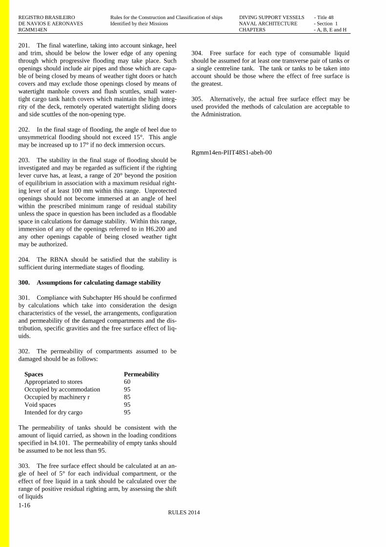
302. The permeability of compartments assumed to be
damaged should be as follows:
Spaces Permeability
Appropriated to stores 60
Occupied by accommodation 95
Occupied by machinery r 85
Void spaces 95
Intended for dry cargo 95
The permeability of tanks should be consistent with the
amount of liquid carried, as shown in the loading conditions
specified in h4.101. The permeability of empty tanks should
be assumed to be not less than 95.
303. The free surface effect should be calculated at an an-
gle of heel of 5° for each individual compartment, or the
effect of free liquid in a tank should be calculated over the
range of positive residual righting arm, by assessing the shift
of liquids
304. Free surface for each type of consumable liquid
should be assumed for at least one transverse pair of tanks or
a single centreline tank. The tank or tanks to be taken into
account should be those where the effect of free surface is
the greatest.
305. Alternatively, the actual free surface effect may be
used provided the methods of calculation are acceptable to
the Administration.
Rgmm14en-PIIT48S1-abeh-00