Embed Size (px)
Citation preview
8/3/2019 Chapter Three(FM)Update
http://slidepdf.com/reader/full/chapter-threefmupdate 1/38
1
CHAPTER 3
Frequency Modulation (fm)
8/3/2019 Chapter Three(FM)Update
http://slidepdf.com/reader/full/chapter-threefmupdate 2/38
2
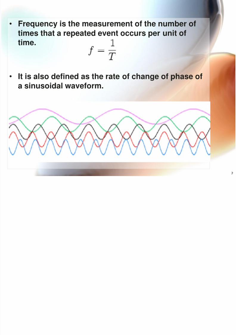
• Frequency is the measurement of the number oftimes that a repeated event occurs per unit oftime.
• It is also defined as the rate of change of phase ofa sinusoidal waveform.
8/3/2019 Chapter Three(FM)Update
http://slidepdf.com/reader/full/chapter-threefmupdate 3/38
3
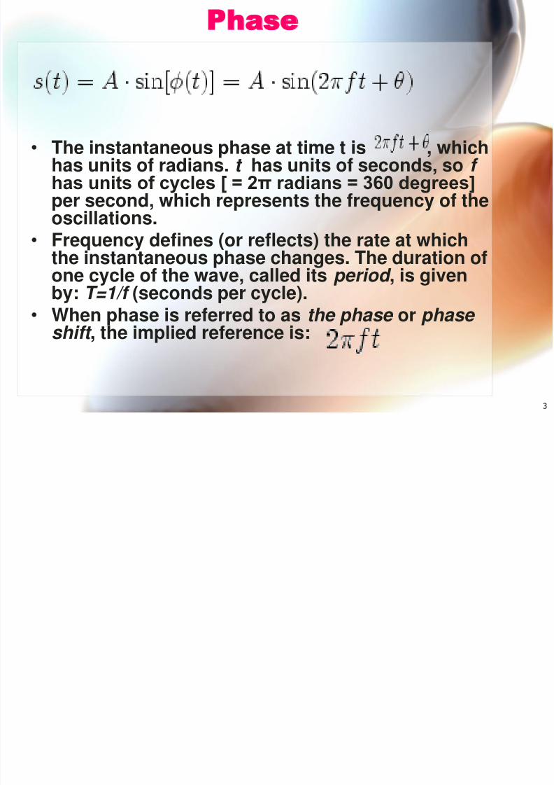
Phase
• The instantaneous phase at time t is , whichhas units of radians. t has units of seconds, so f has units of cycles [ = 2π radians = 360 degrees]per second, which represents the frequency of theoscillations.
• Frequency defines (or reflects) the rate at whichthe instantaneous phase changes. The duration ofone cycle of the wave, called its period , is givenby: T=1/f (seconds per cycle).
• When phase is referred to as the phase or phase shift , the implied reference is:
8/3/2019 Chapter Three(FM)Update
http://slidepdf.com/reader/full/chapter-threefmupdate 4/38
4
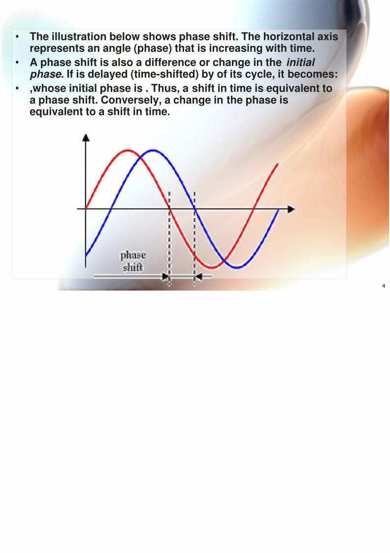
• The illustration below shows phase shift. The horizontal axisrepresents an angle (phase) that is increasing with time.
•
A phase shift is also a difference or change in the initial phase . If is delayed (time-shifted) by of its cycle, it becomes:• ,whose initial phase is . Thus, a shift in time is equivalent to
a phase shift. Conversely, a change in the phase isequivalent to a shift in time.
8/3/2019 Chapter Three(FM)Update
http://slidepdf.com/reader/full/chapter-threefmupdate 5/38
5
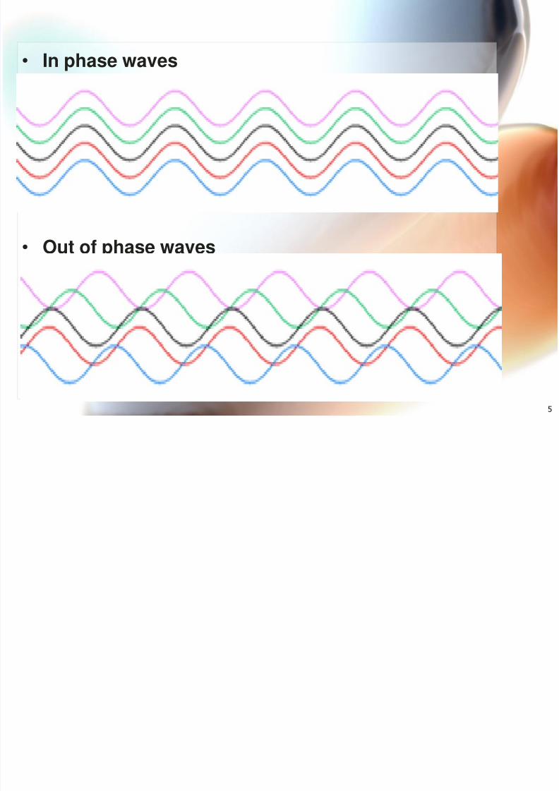
• In phase waves
• Out of phase waves
8/3/2019 Chapter Three(FM)Update
http://slidepdf.com/reader/full/chapter-threefmupdate 6/38
6
• ANGLE MODULATION is often called as FM.Frequency & Phase Modulation (FM & PM) areboth forms of ANGLE MODULATION.
• Because of its superior performance than AM, it is
used extensively for commercial broadcastingradio broadcasting, television soundtransmission, 2-way mobile radio, cellular radio,microwave and satellite communications systems.
Angle Modulation
8/3/2019 Chapter Three(FM)Update
http://slidepdf.com/reader/full/chapter-threefmupdate 7/387
• Frequency Modulation is the process of changingcarrier frequency by the modulating signal whilethe carrier amplitude remains constant.
• As the modulating signal amplitude increases,the carrier frequency increases and vice versa.
• The amount of change in carrier frequencyproduced by the modulating signal is calledFrequency Deviation ( f). Meanwhile, the change inphase is called Phase Deviation ( )
• The deviation is proportional to the amplitude ofthe modulating signal.
Frequency Modulation (FM)
8/3/2019 Chapter Three(FM)Update
http://slidepdf.com/reader/full/chapter-threefmupdate 8/388
• In PM, the phase shift of the carrier is varied bythe amplitude of the modulating signal.
• FM produces pairs of sidebands spaced from thecarrier in multiples of the modulating frequency.
• The modulation index m of FM signal is the ratioof the frequency deviation f d to the modulatingfrequency, f m (m = f d / fm)
• The modulation index determines the number ofsignificant pairs of sidebands in FM signals.
8/3/2019 Chapter Three(FM)Update
http://slidepdf.com/reader/full/chapter-threefmupdate 9/389
FM Bandwidth
•
The Bandwidth of FM signal isproportional to the modulationindex and defined as below:
BW = 2(f d max + fm max )
8/3/2019 Chapter Three(FM)Update
http://slidepdf.com/reader/full/chapter-threefmupdate 10/3810
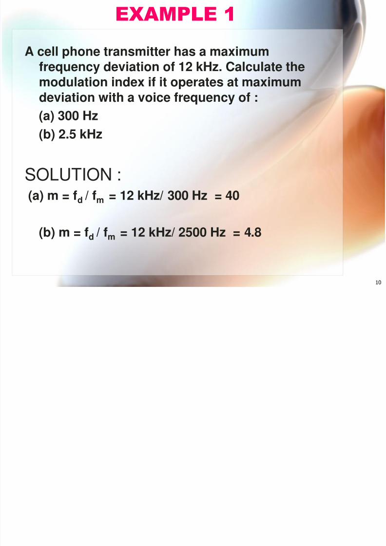
A cell phone transmitter has a maximum
frequency deviation of 12 kHz. Calculate themodulation index if it operates at maximumdeviation with a voice frequency of :(a) 300 Hz
(b) 2.5 kHz
SOLUTION :
(a) m = f d / fm = 12 kHz/ 300 Hz = 40
(b) m = f d / fm = 12 kHz/ 2500 Hz = 4.8
EXAMPLE 1
8/3/2019 Chapter Three(FM)Update
http://slidepdf.com/reader/full/chapter-threefmupdate 11/3811
Advantage of FM over AM
• The primary advantage of FM over AM is itsimmunity to noise.
• Noise is short-duration amplitude variationscaused by lightning, motors, auto ignitions,power transients and other sources.
• Another advantage of FM over AM is the captureeffect that allows the strongest signal onfrequency to dominate without interference fromthe other signal.
• FM has greater transmitter efficiency since classC Amplifier may be used
8/3/2019 Chapter Three(FM)Update
http://slidepdf.com/reader/full/chapter-threefmupdate 12/3812
• FM has wide bandwidth compared to AM.
• The spectrum space taken up by FM signal maybe limited by carefully controlling the deviationratio.
• The circuits used in FM to produce anddemodulate FM is more complex and expensivethan AM circuits.
Disadvantage of FM over AM
8/3/2019 Chapter Three(FM)Update
http://slidepdf.com/reader/full/chapter-threefmupdate 13/3813
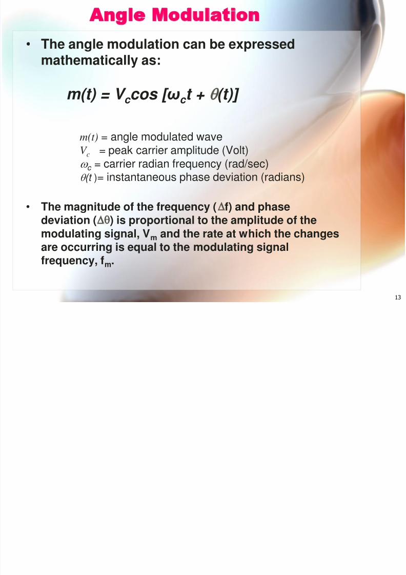
Angle Modulation• The angle modulation can be expressed
mathematically as:
• The magnitude of the frequency ( f) and phasedeviation ( ) is proportional to the amplitude of themodulating signal, V m and the rate at which the changesare occurring is equal to the modulating signalfrequency, f m .
m(t) = angle modulated waveV c = peak carrier amplitude (Volt) c = carrier radian frequency (rad/sec) (t )= instantaneous phase deviation (radians)
m(t) = V c cos [ ω c t + (t)]
8/3/2019 Chapter Three(FM)Update
http://slidepdf.com/reader/full/chapter-threefmupdate 14/3814
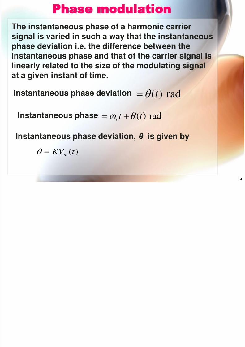
The instantaneous phase of a harmonic carriersignal is varied in such a way that the instantaneousphase deviation i.e. the difference between theinstantaneous phase and that of the carrier signal islinearly related to the size of the modulating signalat a given instant of time.
Phase modulation
rad)(t
Instantaneous phase rad)(t t c
Instantaneous phase deviation
)( t KV m
Instantaneous phase deviation, θ is given by
8/3/2019 Chapter Three(FM)Update
http://slidepdf.com/reader/full/chapter-threefmupdate 15/3815
V V rad
K
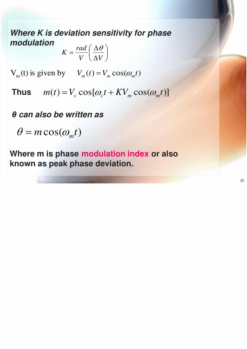
)]cos(cos[)( t KV t V t m mmcc
Where K is deviation sensitivity for phase
modulation
)cos()(bygivenis(t)Vm t V t V mmm
Thus
)cos( t m m
θ can also be written as
Where m is phase modulation index or alsoknown as peak phase deviation.
8/3/2019 Chapter Three(FM)Update
http://slidepdf.com/reader/full/chapter-threefmupdate 16/3816
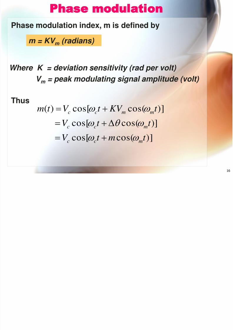
Phase modulation
Where K = deviation sensitivity (rad per volt)
V m = peak modulating signal amplitude (volt)
m = KV m (radians)
)]cos(cos[)]cos(cos[
)]cos(cos[)(
t mt V t t V
t KV t V t m
mcc
mcc
mmcc
Thus
Phase modulation index, m is defined by
8/3/2019 Chapter Three(FM)Update
http://slidepdf.com/reader/full/chapter-threefmupdate 17/3817
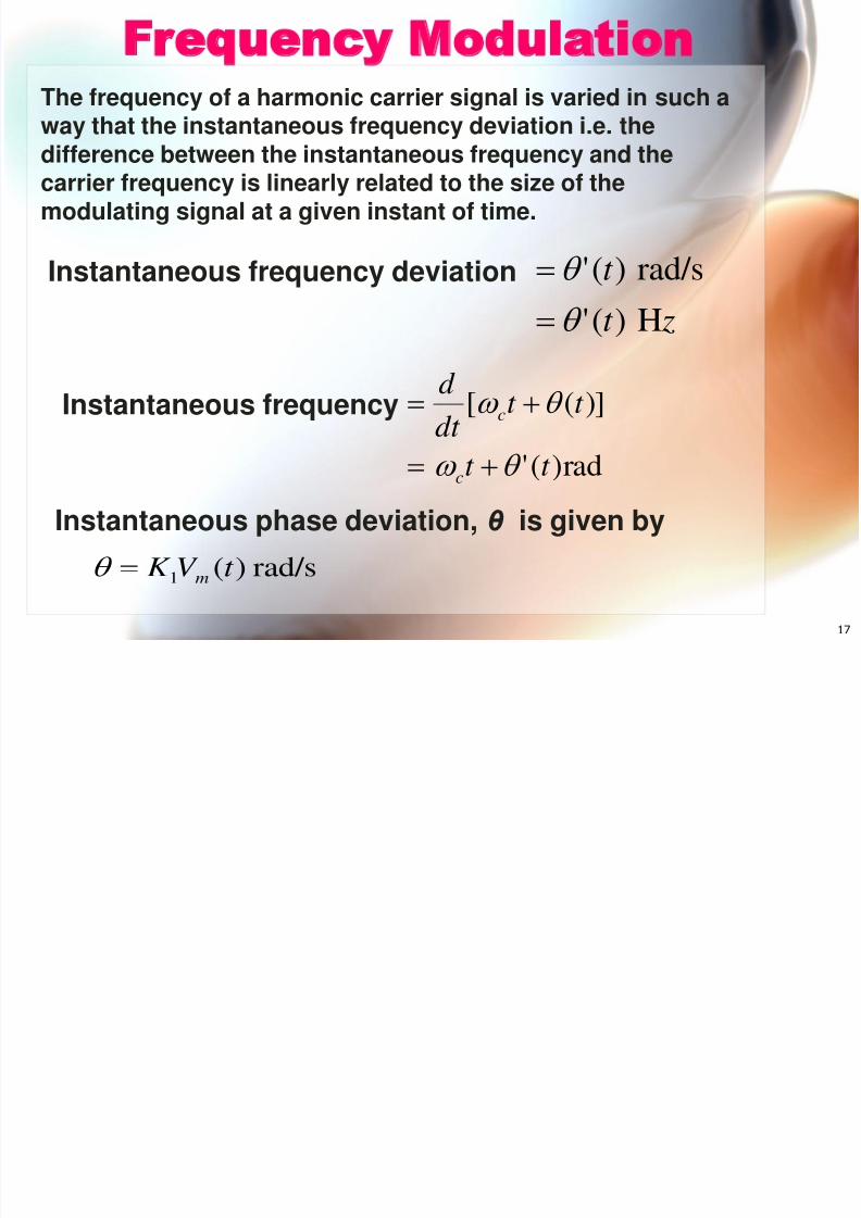
Frequency ModulationThe frequency of a harmonic carrier signal is varied in such away that the instantaneous frequency deviation i.e. thedifference between the instantaneous frequency and thecarrier frequency is linearly related to the size of themodulating signal at a given instant of time.
zt
t
H)('
rad/s)('
Instantaneous frequency
rad)('
)]([
t t
t t dt d
c
c
Instantaneous frequency deviation
rad/s)(1t V K
m
Instantaneous phase deviation, θ is given by

8/3/2019 Chapter Three(FM)Update
http://slidepdf.com/reader/full/chapter-threefmupdate 18/3818
V V srad K
/ 1
)]sin(cos[
])cos(cos[
])cos(cos[
)(cos[)(
1
1
1
t V K
t V
t V K t V
t V K t V
t t V t m
mm
mcc
mmcc
mmcc
cc
Where K 1 is deviation sensitivity for phase modulation
)cos()(bygivenis(t)Vm t V t V mmm
Thus
8/3/2019 Chapter Three(FM)Update
http://slidepdf.com/reader/full/chapter-threefmupdate 19/3819
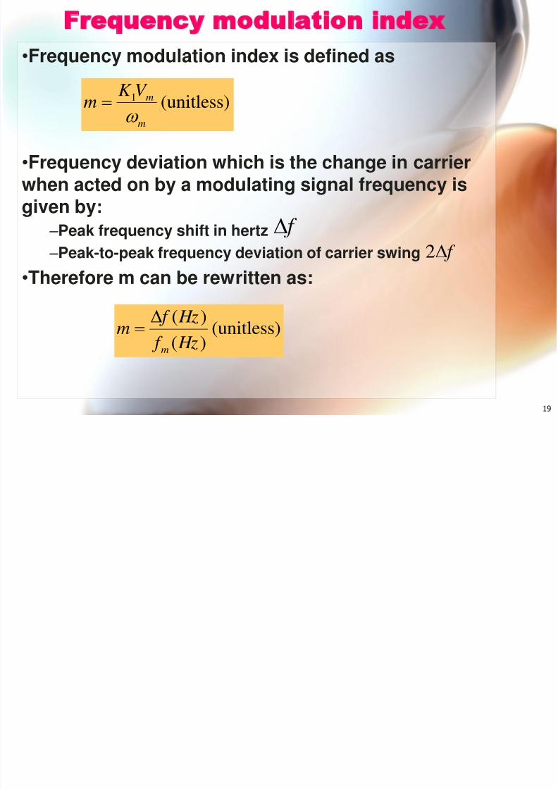
Frequency modulation index• Frequency modulation index is defined as
• Frequency deviation which is the change in carrierwhen acted on by a modulating signal frequency isgiven by:
– Peak frequency shift in hertz – Peak-to-peak frequency deviation of carrier swing
• Therefore m can be rewritten as:
(unitless)1
m
mV K m
f f 2
(unitless))()(
Hz f Hz f
mm
8/3/2019 Chapter Three(FM)Update
http://slidepdf.com/reader/full/chapter-threefmupdate 20/3820
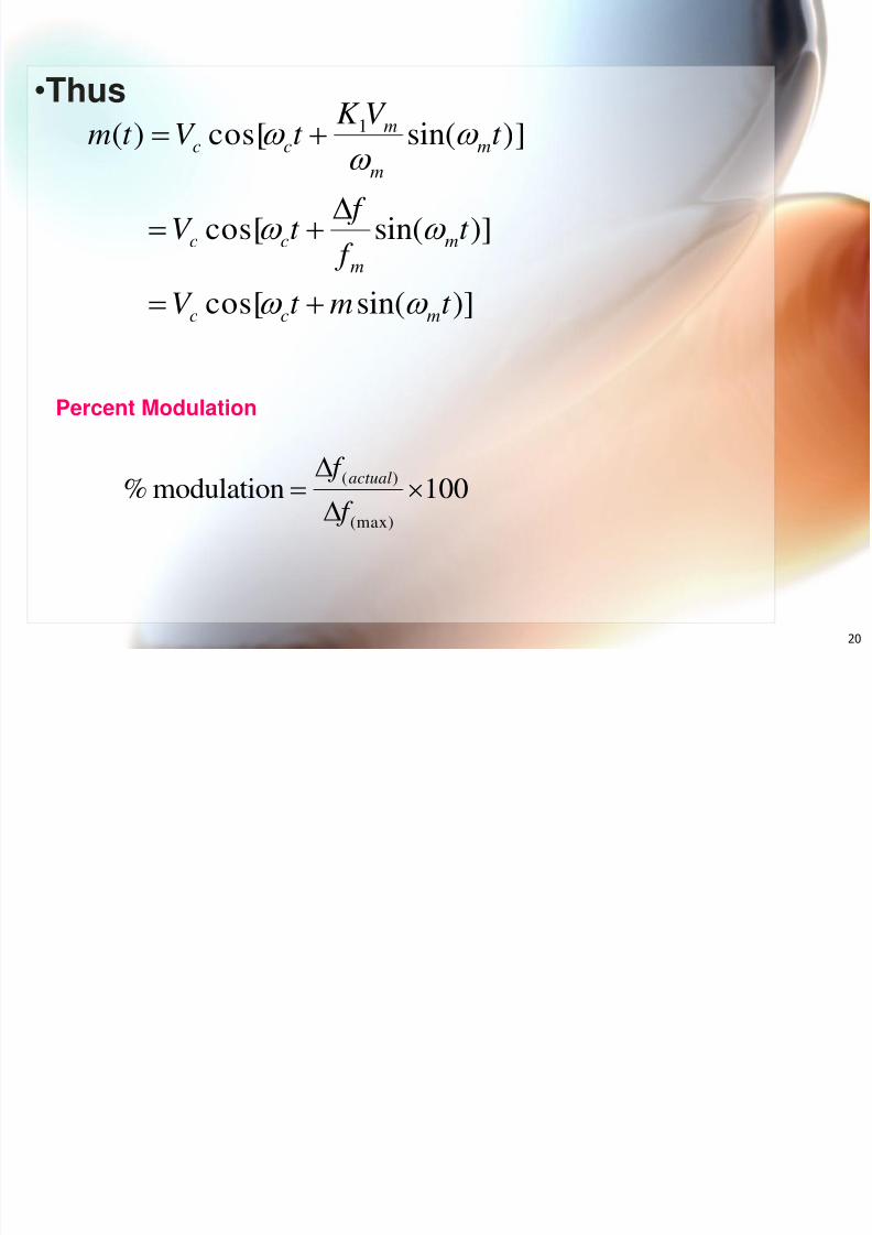
• Thus
)]sin(cos[
)]sin(cos[
)]sin(cos[)( 1
t mt V
t f
f t V
t V K
t V t m
mcc
mm
cc
mm
m
cc
Percent Modulation
100modulation%(max)
)(
f f actual
8/3/2019 Chapter Three(FM)Update
http://slidepdf.com/reader/full/chapter-threefmupdate 21/3821
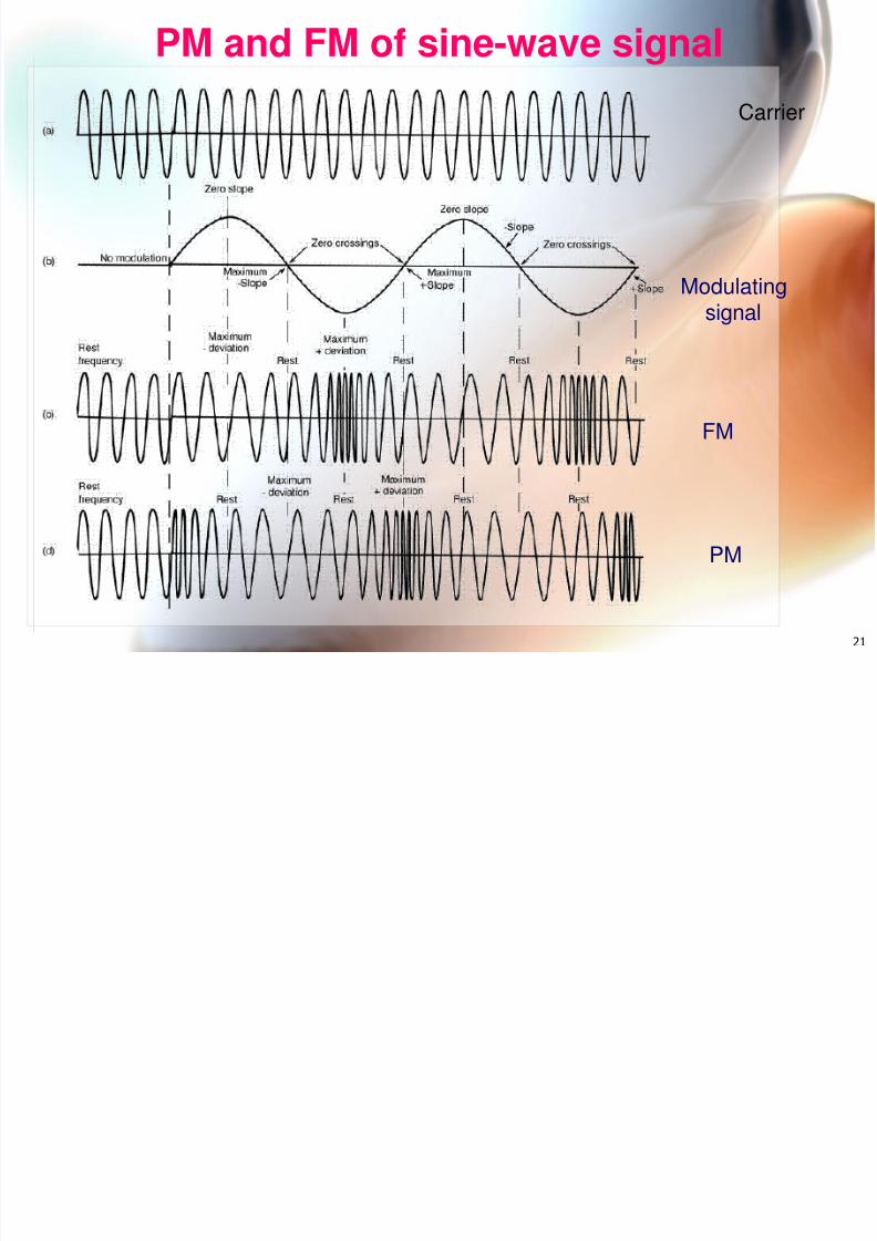
PM and FM of sine-wave signal
FM
PM
Carrier
Modulatingsignal
8/3/2019 Chapter Three(FM)Update
http://slidepdf.com/reader/full/chapter-threefmupdate 22/38
22
8/3/2019 Chapter Three(FM)Update
http://slidepdf.com/reader/full/chapter-threefmupdate 23/38
23
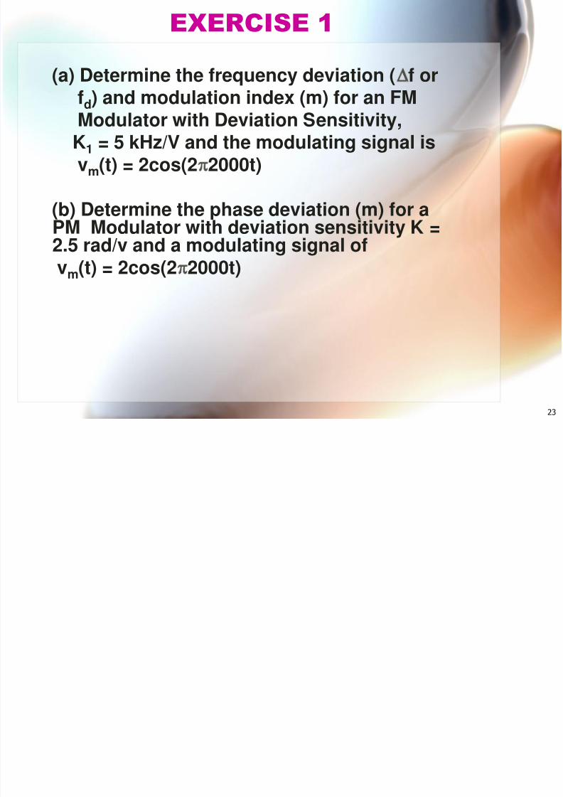
EXERCISE 1
(a) Determine the frequency deviation ( f or
fd) and modulation index (m) for an FMModulator with Deviation Sensitivity,
K1 = 5 kHz/V and the modulating signal isvm(t) = 2cos(2 2000t)
(b) Determine the phase deviation (m) for aPM Modulator with deviation sensitivity K =2.5 rad/v and a modulating signal ofvm(t) = 2cos(2 2000t)
8/3/2019 Chapter Three(FM)Update
http://slidepdf.com/reader/full/chapter-threefmupdate 24/38
24
FM & PM Modulator & Demodulator
• A Phase Modulator is a circuit in which the
carrier is varied in such a way that itsinstantaneous phase is proportional to themodulating signal.
•
A Frequency Modulator is a circuit in whichthe carrier is varied in such a way that itsinstantaneous phase is proportional to theintegral of the modulating signal.
8/3/2019 Chapter Three(FM)Update
http://slidepdf.com/reader/full/chapter-threefmupdate 25/38
25
•
PM Modulator = Differentiator followed byan FM Modulator
• PM Demodulator = FM demodulator followedby an integrator
• FM modulator = integrator followed by a PMModulator
• FM Demodulator = PM demodulator followedby a differentiator
8/3/2019 Chapter Three(FM)Update
http://slidepdf.com/reader/full/chapter-threefmupdate 26/38
26
• For a given input signal, an FM broadcast-band transmitter has frequency deviation, f= 20 kHz. Determine the frequency deviation,
f if the amplitude of the modulating signalincreases by a factor of 2.5
EXERCISE 2
8/3/2019 Chapter Three(FM)Update
http://slidepdf.com/reader/full/chapter-threefmupdate 27/38
27
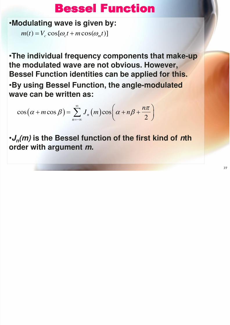
Bessel Function• Modulating wave is given by:
• The individual frequency components that make-upthe modulated wave are not obvious. However,Bessel Function identities can be applied for this.• By using Bessel Function, the angle-modulatedwave can be written as:
• J n (m) is the Bessel function of the first kind of n thorder with argument m .
cos cos cos2n
n
nm J m n
)]cos(cos[)( t mt V t m mcc
8/3/2019 Chapter Three(FM)Update
http://slidepdf.com/reader/full/chapter-threefmupdate 28/38
28
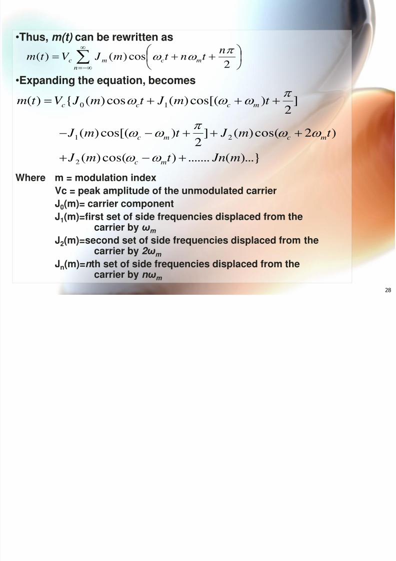
• Thus, m(t) can be rewritten as
• Expanding the equation, becomes
Where m = modulation indexVc = peak amplitude of the unmodulated carrierJ
0(m)= carrier component
J 1(m)=first set of side frequencies displaced from thecarrier by ω m
J 2(m)=second set of side frequencies displaced from thecarrier by 2 ω m
J n(m)= n th set of side frequencies displaced from the
carrier by n ω
m
n
mcmc
nt nt m J V t m
2cos)()(
)...}(.......)cos()(
)2cos()(]2
)cos[()(
]2
)cos[()(cos)({)(
2
21
10
m Jnt m J
t m J t m J
t m J t m J V t m
mc
mcmc
mccc
8/3/2019 Chapter Three(FM)Update
http://slidepdf.com/reader/full/chapter-threefmupdate 29/38
29
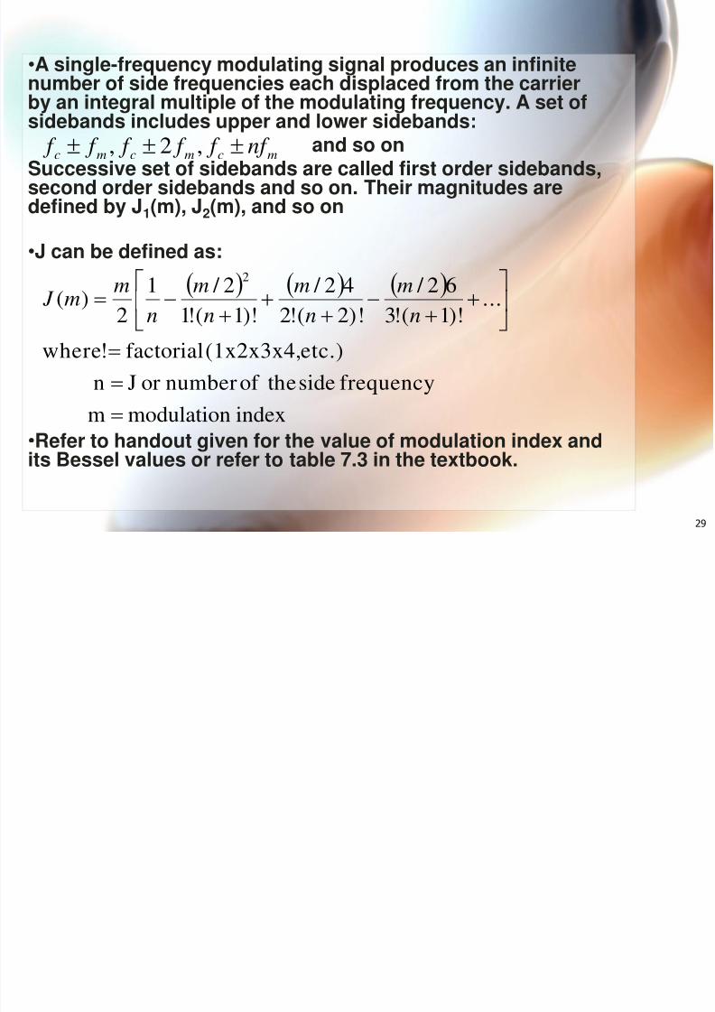
• A single-frequency modulating signal produces an infinitenumber of side frequencies each displaced from the carrierby an integral multiple of the modulating frequency. A set of
sidebands includes upper and lower sidebands:and so onSuccessive set of sidebands are called first order sidebands,second order sidebands and so on. Their magnitudes aredefined by J 1(m), J 2(m), and so on
• J can be defined as:
• Refer to handout given for the value of modulation index andits Bessel values or refer to table 7.3 in the textbook.
indexmodulationm frequencysidetheof numberorJn
etc.)(1x2x3x4,factorial!where
...)!1(!362 /
)!2(!242 /
)!1(!12 / 1
2)(
2
nm
nm
nm
nm
m J
mcmcmc nf f f f f f ,2,
8/3/2019 Chapter Three(FM)Update
http://slidepdf.com/reader/full/chapter-threefmupdate 30/38
30
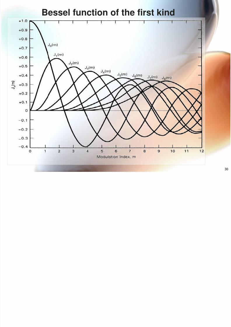
Bessel function of the first kind
d d h f l d l
8/3/2019 Chapter Three(FM)Update
http://slidepdf.com/reader/full/chapter-threefmupdate 31/38
31
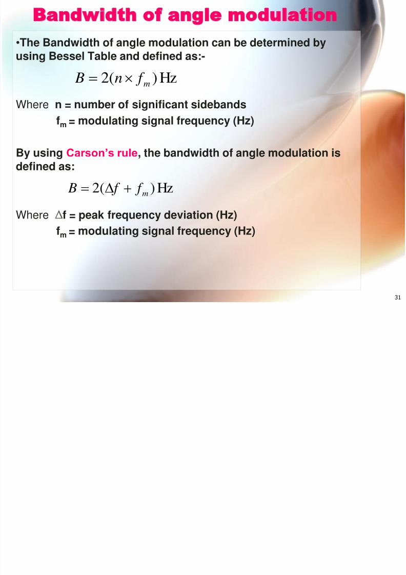
Bandwidth of angle modulation• The Bandwidth of angle modulation can be determined byusing Bessel Table and defined as:-
Where n = number of significant sidebandsfm = modulating signal frequency (Hz)
By using Carson’s rule , the bandwidth of angle modulation isdefined as:
Where ∆ f = peak frequency deviation (Hz)fm = modulating signal frequency (Hz)
Hz)(2 m f f B
Hz)(2 m f n B
EXAMPLE 2
8/3/2019 Chapter Three(FM)Update
http://slidepdf.com/reader/full/chapter-threefmupdate 32/38
32
For FM Modulator with frequency deviation of 10kHz, modulating signal frequency of 10 kHz,Carrier amplitude voltage of 50V and Carrierfrequency of 500 kHz, determine the following:
(a) Minimum Bandwidth using Bessel table(b) Minimum Bandwidth using Carson’s rule (c) Amplitudes of the side frequencies and plotthe output frequency spectrum
EXAMPLE 2 :
S l i
8/3/2019 Chapter Three(FM)Update
http://slidepdf.com/reader/full/chapter-threefmupdate 33/38
33
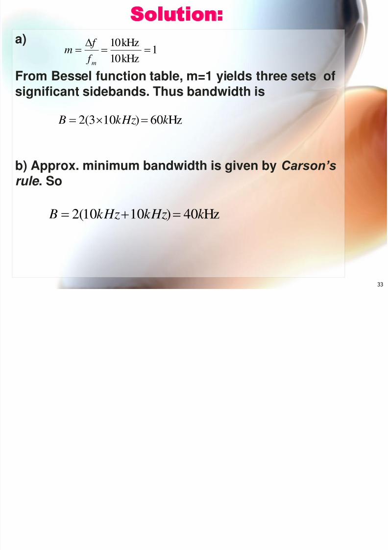
Solution:a)
From Bessel function table, m=1 yields three sets ofsignificant sidebands. Thus bandwidth is
b) Approx. minimum bandwidth is given by Carson’s
rule . So
1kHz10kHz10
m f f
m
Hz60)103(2 k kHz B
Hz40)1010(2 k kHzkHz B
8/3/2019 Chapter Three(FM)Update
http://slidepdf.com/reader/full/chapter-threefmupdate 34/38
34
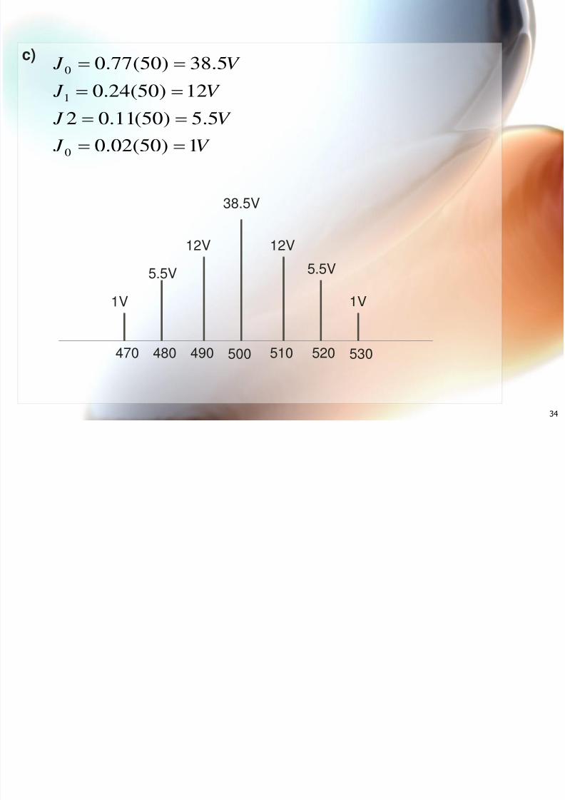
c)
V J
V J
V J
V J
1)50(02.0
5.5)50(11.02
12)50(24.0
5.38)50(77.0
0
1
0
38.5V
12V12V
5.5V5.5V
1V1V
500 510 520 530490480470
EXAMPLE 3
8/3/2019 Chapter Three(FM)Update
http://slidepdf.com/reader/full/chapter-threefmupdate 35/38
35
Determine the deviation & ratio andbandwidth for FM transmitter withfrequency deviation of 75 kHz andmaximum modulating signal of 15 kHz.
EXAMPLE 3
P C l l ti
8/3/2019 Chapter Three(FM)Update
http://slidepdf.com/reader/full/chapter-threefmupdate 36/38
36
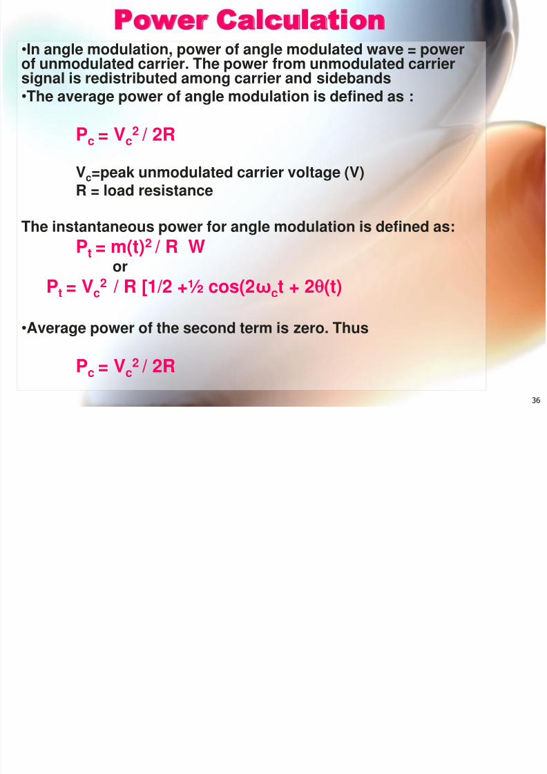
Power Calculation• In angle modulation, power of angle modulated wave = powerof unmodulated carrier. The power from unmodulated carriersignal is redistributed among carrier and sidebands•
The average power of angle modulation is defined as :
P c = Vc2 / 2R
Vc=peak unmodulated carrier voltage (V)
R = load resistance
The instantaneous power for angle modulation is defined as:P t = m(t) 2 / R W
or
P t = Vc2
/ R [1/2 +½ cos(2 ω ct + 2 (t)• Average power of the second term is zero. Thus
P c = Vc2 / 2R
8/3/2019 Chapter Three(FM)Update
http://slidepdf.com/reader/full/chapter-threefmupdate 37/38
37
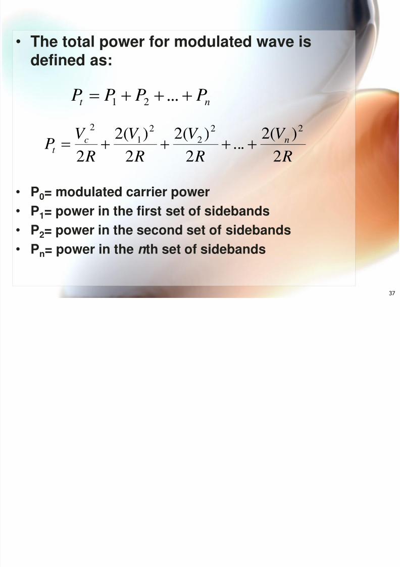
• The total power for modulated wave isdefined as:
• P 0= modulated carrier power•
P 1= power in the first set of sidebands• P 2= power in the second set of sidebands• P n= power in the n th set of sidebands
RV
RV
RV
RV
P nct 2)(2
...2)(2
2)(2
2
22
2
2
1
2
nt PPPP ...21
EXAMPLE 4
8/3/2019 Chapter Three(FM)Update
http://slidepdf.com/reader/full/chapter-threefmupdate 38/38
Determine the unmodulated carrier power for
FM Modulator with modulation index of 1,modulating signal of v m(t) = V msin(2 1000t)and carrier signal of v c(t) = V csin(2 500kt),assume load resistance, R L = 50 . Alsodetermine the total power for the anglemodulation.
EXAMPLE 4