Embed Size (px)
Citation preview

In this chapter, existing components of the airport are evaluated so that the capacities of the overall system are identified. Once identified, the existing capacity is compared to the forecast activity levels prepared in Chapter Two to determine where deficiencies currently exist or may be expected to materialize in the future. Once deficiencies in a component are identified, a more specific determination of the approximate sizing and timing of the new facilities can be made.
The objective of this effort is to identify, in general terms, the adequacy of the existing airport facilities and outline what new facilities may be needed and when they may be needed to accommodate forecast demands. Having established these facility requirements, alternatives for providing these facilities will be evaluated in Chapter Four to determine the most cost-effective and efficient means for implementation.
The cost-effective, efficient, and orderly development of an airport should rely more upon actual demand levels experienced at an airport rather than a time-based forecast figure. In order to develop a master plan that is demand-based rather than time-based, a series of planning horizon milestones have been established for Hollister Municipal Airport that take into consideration the reasonable range of aviation demand projections.
It is important to consider that the actual activity at the airport may be higher or lower than projected. By planning according to activity
3-1
Chapter Three
FacilityRequirements

3-2
milestones, the resultant plan can accommodate unexpected shifts, or changes in aviation demand. It is important for the plan to accommodate these changes so that airport officials can respond to unexpected changes in a timely fashion. As a result, these milestones provide flexibility, while potentially extending this plan’s useful life if aviation trends slow over the period. The most important reason for utilizing milestones is they allow the
airport to develop facilities according to need generated by actual demand levels. The demand-based schedule provides flexibility in development, as development schedules can be slowed or expedited according to actual demand at any given time over the planning period. The resultant plan provides airport officials with a financially responsible and need-based program. Table 3A presents the planning horizon milestones for each activity demand category.
TABLE 3A Planning Horizon Activity Levels Hollister Municipal Airport
2002 Short Term
Intermediate Term
Long Term
Based Aircraft 195 240 285 380 Annual Operations 57,300 74,400 91,200 129,600
AIRFIELD REQUIREMENTS Airfield requirements include the need for those facilities related to the arrival and departure of aircraft. These facilities comprise the following items: • Runways • Taxiways • Navigational Aids • Instrument Approach Procedures • Airfield Marking and Lighting AIRFIELD CAPACITY The capacity of the airfield is affected by several factors including airfield
layout, meteorological conditions, aircraft mix, runway use, aircraft arrivals, aircraft touch-and-go activity, and exit taxiway locations. An airport’s airfield capacity is expressed in terms of its annual service volume (ASV). Annual service volume is a reasonable estimate of the maximum level of aircraft operations that can be accommodated in a year. Pursuant to Federal Aviation Administration (FAA) guidelines, detailed in the FAA Advisory Circular 150/5060-5, Airport Capacity and Delay, the annual service volume of an intersecting runway configuration normally exceeds 200,000 annual operations. Since the forecasts for the airport indicate that activity throughout the planning period may only reach 129,600 annual operations,

3-3
the capacity of the existing airfield system will not be reached and the airfield can meet operational demands. Therefore, there is no requirement for the consideration of a parallel runway. RUNWAY ORIENTATION Hollister Municipal Airport is served by two intersecting runways. The primary runway (Runway 13-31) runs northwest-southeast. The crosswind runway (Runway 6-24) runs northeast-southwest. For the operational safety of an airport, the primary runway should be oriented as close as possible to the direction of the prevailing wind. This reduces the percentage of time that crosswind conditions (wind flowing perpendicular to the travel of the aircraft) could make the primary runway inoperable and unsafe for aircraft landing and taking off. FAA design standards specify that a crosswind runway should be made available when the primary runway orientation provides less than 95 percent wind coverage for any aircraft forecast to use the airport on a regular basis. The 95 percent wind coverage is computed on the basis of the crosswind component not exceeding 10.5 knots for small aircraft weighing less than 12,500 pounds, and not exceeding 13 to 20 knots for aircraft weighing more than 12,500 pounds. Wind data specific to Hollister Municipal Airport is not available due to the lack of an automated weather observation system (AWOS) at the airport. In instances when wind data
specific to the airport is not available, FAA AC 150/5300-13, Airport Design, provides for the wind analysis to be based in part on wind data from a nearby recording station. For this Master Plan, the closest recording station with available wind data was Salinas, California. Table 3B summarizes wind coverage for Hollister Municipal Airport using the wind data from Salinas, California. As shown in the table, the combined wind coverage for Runways 13-31 and 6-24 exceed 99 percent for all crosswind components. Therefore, based only on this analysis, there is no need to consider a new runway orientation at Hollister Municipal Airport. However, this analysis should not be construed to indicate that there should only be one runway orientation at the airport. This analysis is limited by the fact that Salinas Municipal Airport is not exactly comparable to Hollister Municipal Airport. Salinas Municipal Airport is located approximately 15 nautical miles southwest of Hollister Municipal Airport. There are significant geographical features, including rising terrain as high as 3,000 feet, between each facility. This leads to significantly different wind patterns and climatological conditions at each airport. The difference in wind patterns can be shown by the difference in the primary runway orientations between each airport. The primary runway at Salina Municipal Airport is Runway 8-26, which is oriented in an east-west direction. As mentioned previously, the primary runway at Hollister Municipal Airport is Runway 13-31 which is oriented in a northwest/

3-4
southeast direction. Salinas Municipal Airport is equipped with Runway 13-31 and Runway 14-32 as well, although these runways are secondary and much shorter. FAA AC 150/5300-13 recognizes that substituting wind data from another airport is only reliable when the terrain between the airports is similar. In situations when the terrain varies significantly, such as between Salinas Municipal Airport and Hollister Municipal Airport, the wind analysis is expected to have only marginal validity. When this occurs, the wind analysis should be augmented with personal observations. Members of the Planning Advisory Committee (PAC) agreed that the Salinas wind data is not comparable to Hollister Municipal
Airport. During most afternoons, the wind at Hollister Municipal Airport is from the west leading to the use of Runway 24 by nearly all aircraft. Recognizing the limitation of the wind data available for this analysis, the wind coverage analysis shown above should not be solely relied upon to make determinations of runway orientation at Hollister Municipal Airport. The existing use of the airport, which requires using Runway 24 on a daily basis, is a better indicator of the needed runway orientations at the airport. The wind coverage analysis should be updated when 10 years of consecutive wind data specific to the airport can be collected using the automated weather observing system (AWOS) at the airport.
TABLE 3B Wind Coverage
Crosswind Component
Runway 13-31
Runway 6-24
Combined
10.5 knots 95.98% 92.50% 99.85% 13.0 knots 98.48% 96.60% 99.95% 16.0 knots 99.76% 98.99% 99.97% 20.0 knots 99.95% 99.71% 99.98%
Source: Salinas, CA, 1/1/93 to 12/31/02 PHYSICAL PLANNING CRITERIA The selection of appropriate FAA design standards for the development and location of airport facilities is based primarily upon the characteristics of the aircraft which are currently using, or are expected to use, the airport. Planning for future aircraft use is of particular importance since design standards are used to
plan separation distances between facilities. These standards must be determined now since the relocation of these facilities would likely be extremely expensive at a later date. The most important characteristics in airfield planning are the approach speed and wingspan of the critical design aircraft anticipated to use the airport now and in the future. The critical design aircraft is defined as

3-5
the most demanding category of aircraft which conducts 500 or more operations per year at the airport. The FAA has established a coding system to relate airport design criteria to the operational and physical characteristics of aircraft expected to use the airport. This code, referred to as the airport reference code (ARC), has two components: the first component, depicted by a letter, is the aircraft approach category and relates to aircraft approach speed (operational characteristic); the second component, depicted by a Roman numeral, is the airplane design group (ADG) and relates to aircraft wingspan (physical characteristic). Generally, aircraft approach speed applies to runways and runway-related facilities, while airplane wingspan primarily relates to separation criteria involving taxiways, taxilanes, and landside facilities. According to FAA Advisory Circular (AC) 150/5300-13, Airport Design, Change 7, an aircraft’s approach category is based upon 1.3 times its stall speed in landing configuration at that aircraft’s maximum certificated weight. The five approach categories used in airport planning are as follows: Category A: Speed less than 91 knots. Category B: Speed 91 knots or more, but less than 121 knots. Category C: Speed 121 knots or more, but less than 141 knots. Category D: Speed 141 knots or more, but less than 166 knots. Category E: Speed greater than 166 knots.
The airplane design group (ADG) is based upon the aircraft’s wingspan. The six ADGs used in airport planning are as follows: Group I: Up to but not including 49 feet. Group II: 49 feet up but not including 79 feet. Group III: 79 feet up to but not including 118 feet. Group IV: 118 feet up to but not including 171 feet. Group V: 171 feet up to but not including 214 feet. Group VI: 214 feet or greater. As shown on Exhibit 3A, the airport does not currently, nor is it expected to, serve aircraft in ARCs C-III, D-III, C-IV, D-IV, or D-V. These are large transport aircraft commonly used by commercial air carriers. As mentioned previously in Chapter Two, Hollister Municipal Airport presently serves general aviation activity. This role is expected to remain the same through the planning period. FAA advises designing airfield facilities to meet the requirements of the airport’s most demanding aircraft, or critical aircraft. As discussed above, this is the aircraft, or group of aircraft (defined by ARC), with at least 500 operations at the airport. In order to determine future facility needs, an ARC should first be determined, and then appropriate airport design criteria can be applied. This begins with a review of aircraft currently using the airport and those expected to use the airport through the planning period.

3-6
Hollister Municipal Airport is currently utilized by all types of general aviation aircraft ranging from small single-engine and multi-engine aircraft to turboprop and business jets, gliders, helicopters, and ultralights. Helicopters are not assigned an ARC; ultralights fall with ARC A-I. Most based aircraft at Hollister Municipal Airport fall within ARCs A-I and B-I, and include a variety of single-engine and multi-engine piston aircraft. The California Department of Forestry (CDF) operates the Grumman S-2 for wildfire-fighting activities. The S-2 is a multi-engine piston aircraft that falls within ARC B-II. The CDF conducted 1,182 operations in 2001 and 942 operations in 2002 with the S-2. Operations were conducted on both runways. The type of transient aircraft using the airport is more diverse than the
type of aircraft based at the airport and includes single-engine and multi-engine piston aircraft, as well as turboprop aircraft and various business jets within ARCs B-I, B-II, C-I, C-II, and D-I. In an effort to more clearly define business jet use of the airport, a review of instrument flight data for business jet operations at Hollister Municipal Airport was completed using 10 months of actual data in 2003 (February through December). This data indicates that 18 different models of business jets have used Hollister Municipal Airport. The aircraft models included the IAI Jet Commander 1121, North American Saberliner 65, four models of the Cessna Citation jet, Learjet 25 and 35, Hawker 800XP, Canadair Challenger, Hawker Sidley 600A, and Beechraft 400A. Table 3C summarizes the percentage of operations by aircraft within each ARC.
TABLE 3C Estimated Annual Business Jet Operations By ARC
Airport Reference Code Percent of Operations Recorded Operations B-I B-II C-I C-II D-I
21% 25% 37% 8% 10%
42 50 76 16 20
Total 100% 204 Source: FAA, February 5, 2003 through December 2, 2003
Critical Design Aircraft Conclusion Considering that the Grumman S-2 (ARC B-II) conducts more than 500
operations annually at the airport, this aircraft is the current critical design aircraft. When coupled with business jet activity, aircraft operations within ARC B-II are

• Beech Baron 55• Beech Bonanza• Cessna 150• Cessna 172• Piper Archer• Piper Seneca
• Beech Baron 58• Beech King Air 100• Cessna 402• Cessna 421• Piper Navajo• Piper Cheyenne• Swearingen Metroliner• Cessna Citation I
• Super King Air 200• Cessna 441• DHC Twin Otter
• Super King Air 300• Beech 1900 • Jetstream 31 • Falcon 10, 20, 50 • Falcon 200, 900• Citation II, III, IV, V• Saab 340 • Embraer 120
• DHC Dash 7• DHC Dash 8• DC-3• Convair 580• Fairchild F-27• ATR 72• ATP
A-I
B-I less than 12,500 lbs.
B-II less than 12,500 lbs.
B-I, II over 12,500 lbs.
A-III, B-III
• Lear 25, 35, 55• Israeli Westwind• HS 125
• Gulfstream II, III, IV• Canadair 600• Lockheed JetStar• Super King Air 350
• Boeing Business Jet• B 727-200 • B 737-300 Series• MD-80, DC-9• Fokker 70, 100• A319, A320• Gulfstream V• Global Express
• B-757 • B-767 • DC-8-70• DC-10• MD-11• L1011
• B-747 Series• B-777
C-I, D-I
C-II, D-II
C-III, D-III
C-IV, D-IV
D-V
Note: Aircraft pictured is identified in bold type.
Exhibit 3AAIRPORT REFERENCE CODES
01M
P12
-1A
-12/
11/0
3
HollisterMunicipalAirport

3-7
estimated to conduct between 1,100 and 1,400 operations annually. Therefore, the current ARC for Hollister Municipal Airport is ARC B-II. As discussed in Chapter Two, the potential exists in the future for increased use of the airport by business jet aircraft. This follows with the national trend of increased business and corporate use of turbojet aircraft, strong sales, and deliveries of business jet aircraft, and expanded fractional ownership programs. Currently, business jets conduct over 200 operations annually at the airport. The transfer of aviation demand from the Bay Area also increases the potential for increased use by business jet aircraft. Business jets within approach categories B and C, and ADG I and II represent 90 percent of the operational business jets. Therefore, by applying ARC C-II design and safety standards to the airport, it is expected that the airport would adequately serve over 90 percent of the operational business jets. To safely accommodate business jet aircraft at Hollister Municipal Airport in the future, the airport would need to conform to ARC C-II design standards. Thus, ARC B-II design criterion apply to the current design and use of Runway 13-31, and ARC C-II design criterion applies to the ultimate design and use of Runway 13-31. It is not necessary to design all airfield elements to the same ARC. Since the CDF Grumman S-2 uses Runway 6-24 almost half of the time, ARC B-II
design standards are applicable to Runway 6-24. This designation is not expected to change in the future as the length of Runway 6-24 will limit larger business jet aircraft use. The design of taxiway and apron areas should consider the wingspan requirements of the most demanding aircraft to operate within that specific functional area on the airport. The airfield taxiways, aircraft maintenance and repair hangar areas, and transient apron areas should consider ADG II design requirements to accommodate the wingspan requirements of the largest general aviation aircraft to operate at the airport. T-hangar and small conventional hangar areas should consider ADG I requirements as these commonly serve smaller single and multi-engine piston aircraft. RUNWAY LENGTH The determination of runway length requirements for an airport is based on four primary factors: airport elevation; mean maximum temperature of the hottest month; runway gradient (difference in elevation of each runway end); and critical aircraft type expected to use the airport. Aircraft performance declines as the elevation, temperature, and gradients increase. For calculating runway length requirements at Hollister Municipal Airport, the airport elevation is 230 feet above mean sea level (MSL) and the mean maximum temperature of

3-8
the hottest month is 83 degrees Fahrenheit (September). For Runway 13-31, there is a 27-foot difference in runway end elevations. The effective runway gradient is 0.4%. For Runway 6-24, the difference in runway end elevations is 1.2 feet. The effective gradient is 0.03 percent. Using the specific data for Hollister Municipal Airport described above, runway length requirements for the various classifications of aircraft that may operate at the airport were examined using the FAA Airport Design computer program, Version 4.2D, which groups general aviation aircraft into several categories, reflecting the percentage of the fleet
within each category and useful load (passengers and fuel) of the aircraft. Table 3D summarizes FAA recommended runway lengths for Hollister Municipal Airport. As mentioned previously, the current critical design aircraft at Hollister Municipal Airport are within ARC B-II. The appropriate FAA runway length planning category for aircraft within ARC B-II is “small airplanes with 10 or more passenger seats.” As shown in the table, the FAA recommends a runway length of 3,700 feet to serve this category of aircraft. This length is exceeded along Runway 13-31. However, Runway 6-24 is 550 feet short of this planning standard.
TABLE 3D FAA Recommended Runway Length Requirements
AIRPORT AND RUNWAY DATA Airport elevation Mean daily maximum temperature of the hottest month
230 feet 83.2 F
RUNWAY LENGTHS RECOMMENDED FOR AIRPORT DESIGN Small airplanes with less than 10 passenger seats 75 percent of these small airplanes 95 percent of these small airplanes 100 percent of these small airplanes
2,510 feet 3,100 feet 3,700 feet
Large airplanes of 60,000 pounds or less 75 percent of these large airplanes at 60 percent useful load 75 percent of these large airplanes at 90 percent useful load
5,400 feet 7,000 feet
Source: FAA Airport Design Computer Program, Version 4.2D. Small airplanes – aircraft weighing less than 12,500 pounds. The length of Runway 6-24 is limited by San Felipe Road to the east and terrain to the west which obstructs the Runway 6 approach surface. The alternatives analysis will examine the extent to which the length of Runway 6-24 can be lengthened to 3,700 feet.
For aircraft within ARC C-II, the appropriate runway length planning category is “75 percent of large airplanes at 90 percent useful load.” This planning category specifies a primary runway length of 7,000 feet. At 6,350 feet, Runway 13-31 falls 650

3-9
feet short of this planning standard. Runway 13-31 is equipped with a 1,170-foot lead-in taxiway that is currently not considered part of the runway. Technically, this portion of the runway should not be used for departure calculations as it is not part of the declared runway length. The alternatives analysis will examine the options available to recapture part of this pavement for use in meeting a 7,000-foot runway length recommend-ation for Runway 13-31. Runway 6-24 is equipped with a 750-foot lead-in taxiway behind the Runway 6 end and a 450-foot lead-in taxiway behind the Runway 24 end. These lead-in taxiways are not currently marked as displaced thresholds or declared a portion of the usable runway length. The alternatives analysis will examine the future use of these pavement areas and their continued retention through the planning period. AIRFIELD DESIGN STANDARDS The FAA has established several imaginary surfaces to protect aircraft operational areas and keep them free from obstructions that could affect the safe operation of aircraft. These include the runway safety area (RSA), object free area (OFA), precision OFA, obstacle free zone (OFZ), and runway protection zones (RPZ). The OFA is defined as a “two dimensional ground area surrounding runways, taxiways, and taxilanes
which are clear of objects except for objects whose location is fixed by function.” The RSA is defined as a “defined surface surrounding the runway prepared or suitable for reducing the risk of damage to airplanes in the event of an overshoot, undershoot, or an excursion from the runway.” The OFZ is defined as “the airspace below 150 feet above the established airport elevation along the runway and extended runway centerline that is required to be clear of all objects (except for frangible items required for navigation of aircraft) in order to provide clearance protection for aircraft landing and taking off from the runway, and for missed approaches.” The OFA is defined as Aa two-dimensional ground area surrounding runways, taxiways, and taxilanes which is clear of objects except for objects whose location is fixed by function.@ The precision OFA applies to runways with a precision instrument approach procedure. The RPZ is defined as “an area off the runway end to enhance the protection of people and property on the ground.” The RPZ is trapezoidal in shape and centered about the extended runway centerline. The dimensions of an RPZ are a function of the runway ARC and approach visibility minimums. Table 3E summarizes the design requirements of these safety areas for each runway at Hollister Municipal Airport. The FAA expects the RSA, OFA, and OFZ areas to be under the control of the airport and free from obstructions. While the FAA prefers that the RPZ be owned

3-10
fee simple, the RPZ can be secured with avigation easements. A review of current airport drawings indicates that Runway 13-31 fully meets ARC B-II design requirements; however, a full analysis of the ability to meet ARC C-II design requirements must be made. This will need to consider the potential of recapturing portions of the lead-in taxiways as runway. If the full lead-in taxiway behind the Runway 31 end were recaptured, the airport would not meet ARC C-II RSA or OFA standards as the RSA and OFA would extend across San Felipe Road. It appears that sufficient area is available behind the
Runway 13 end to meet ARC C-II RSA and OFA requirements. The alternatives analysis to follow will also examine the requirements of FAA Order 5200.8, Runway Safety Area Program. Established in October 1999, the order requires the FAA to make a determination of the status of each RSA at all federally-obligated airports. The objective of the order is for all airports to conform with RSA standards to the extent practicable. The alternatives analysis will follow the guidance in the order, including an analysis of the required options to be considered to ensure RSA standards are met at the airport.
TABLE 3E Airfield Safety Area Dimensions (ft.) ARC B-II
Existing Runway 13-31
ARC C-II Ult.
Runway 13-31 Runway Safety Area (RSA) Width Length Beyond Runway End
150 300
400
1,000 Object Free Area (OFA) Width Length Beyond Runway End
500 300
800
1,000 Precision OFA Width Length Beyond Runway End
N/A N/A
800 200
Obstacle Free Zone (OFZ) Width Length Beyond Runway End
400 200
400 200
Runway Protection Zone (RPZ) Inner Width Outer Width Length
500 700
1,000
Rwy. 31 1,000 1,750 2,500
Rwy. 13 500
1,010 1,700
RUNWAY WIDTH Runway width is primarily determined by the planning ARC for the particular runway. The ultimate
planning ARC for Runway 13-31 is C-II. ARC C-II design standards specify a runway width of 100 feet. Currently, Runway 13-31 is 100 feet wide, meeting this design requirement. ARC

3-11
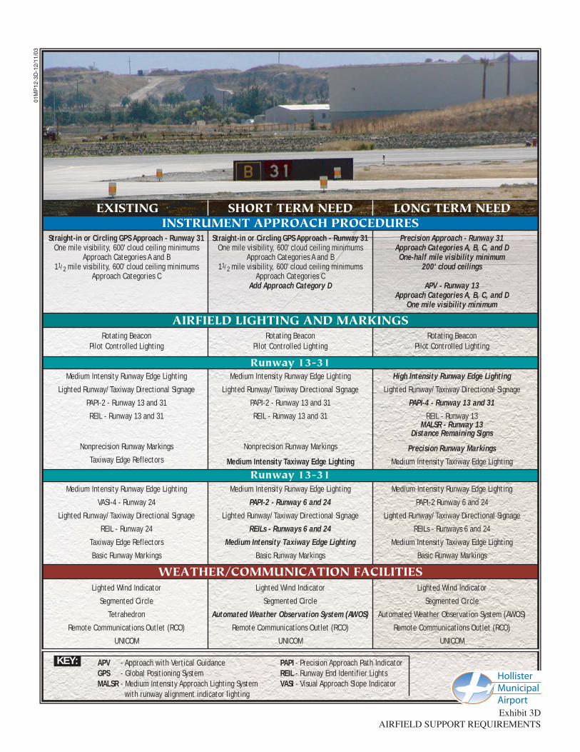
B-I design standards for small aircraft specify a pavement width of 60 feet. Runway 6-24 is 100 feet wide exceeding this requirement. In the future, it will be necessary to analyze the cost-benefit of reducing the width of the runway to meet width standards. This cost- benefit is primarily related to the costs to remove and reconstruct the airfield lighting at the new pavement width. If the cost to remove and reconstruct the airfield lighting is more than the cost to rebuild the pavement, then it is likely that the 100-foot width may be maintained. If it is not, then the runway would need to be rebuilt to 60-feet when the reconstruction of the runway is needed. RUNWAY PAVEMENT STRENGTH The most important feature of airfield pavement is its ability to withstand repeated use by aircraft of significant weight. Presently, both Runways 13-31 and 6-24 have a pavement strength of 30,000 pounds single wheel loading (SWL) and 45,000 dual wheel loading (DWL). Exhibit 3B depicts the pavement strength results of the last pavement evaluation completed for Hollister Municipal Airport. This analysis, completed by the FAA in 1995, determined pavement condition as well as pavement strength for various pavement sections at the airport. This analysis revealed a range of pavement strengths for Hollister Municipal Airport, varying greatly across the
same taxiway or runway. The results of this analysis are presumed to have led to the published pavement strengths for Hollister Municipal Airport. While a SWL strength of 30,000 pounds is sufficient to accommodate the majority of the mix of aircraft expected to use the airport through the planning period, Runway 13-31 should be upgraded to 75,000 DWL to accommodate the larger business jet aircraft within the national fleet. Aircraft weighing more than these planned pavement strength ratings may use the airport on occasion. Prior to their use, an evaluation of the number of annual operations which can be conducted should be determined. The number of operations by heavier aircraft should be closely monitored. TAXIWAYS Taxiways are constructed primarily to facilitate aircraft movements to and from the runway system. Some taxiways are necessary simply to provide access between the aprons and runways, whereas other taxiways become necessary as activity increases at an airport to provide safe and efficient use of the airfield. Taxiway width is determined by the ADG of the most demanding aircraft to use the taxiway. As mentioned previously, the most demanding aircraft to use Runway 13-31 fall within ADG II. According to FAA design standards, the minimum

3-12
taxiway width for ADG II is 35 feet. Taxiways serving Runway 6-24 are only required to be 25 feet wide. Presently, all taxiways at Hollister Municipal Airport are 50 feet wide, exceeding this requirement. Design standards for the separation distances between runways and parallel taxiways are based primarily on the ARC for that particular runway and the type of instrument approach capability. For Runway 13-31, which is served by a GPS approach, ARC B-II design standards specify a runway/taxiway separation distance of 240 feet. ARC C-II design standards specify a runway/taxiway separation distance of 400 feet for runways served by an instrument approach procedure with visibility minimums of less than one mile. Presently, Taxiway A is located 300 feet from the Runway 13-31 centerline. The alternatives analysis will examine options to provide a runway/taxiway separation distance of 400 feet along Runway 13-31 to preserve the ability to accommodate a precision instrument approach in the future. Taxiway C is located 250 feet from the Runway 6-24 centerline. The FAA distance requirement for this taxiway is 150 feet. Since the FAA only requires the parallel taxiway to be 150 feet from the runway, it may be advantageous to examine the benefit of ultimately relocating the taxiway at this distance. The benefit would be measured by the amount of developable property that could be recaptured through the relocation of the taxiway to standard.
The taxiway entrance/exit points at each end of Runway 6-24 are located at an acute angle to the runway. Typically, these taxiways are located perpendicular to the runway to provide better visibility of both the approach and departure paths. The alternatives analysis will examine the options to realigning these taxiways. Additional exit taxiways should be considered for each runway. Additional exit taxiways would reduce the amount of time that aircraft occupy the runway, maximizing airfield capacity and reducing delay. The alternatives analysis will examine the optimum number of exit taxiways and locations, or the mix of aircraft expected to use the airport. Glider activities at the airport should be given special consideration. Glider aircraft require special ground handling prior to and after departure. This increases the amount of time that these aircraft occupy the active runway surface. Consideration may be given to developing dedicated entrance and exit taxiways for the glider aircraft on the north side of Runway 6-24 to accommodate the ground handling of these aircraft. Facility planning should include the development of a full length parallel taxiway west of Runway 13-31 and a full length parallel taxiway north of Runway 6-24. This will facilitate airfield development in these areas of the airport by providing access to the runway system.

Exhibit 3BPAVEMENT STRENGTH RATINGS
01M
P12
-3B
-12/
17/0
3
HH FF
RUNW
AY 6
-24
(3,1
50' x
100
')
RUNW
AY 6
-24
(3,1
50' x
100
')
F EEE CC BA
BA
RUNWAY 13-31 (6,350' x 100')RUNWAY 13-31 (6,350' x 100')RUNWAY 13-31 (6,350' x 100')
RUNW
AY 6
-24
(3,1
50' x
100
')
High
way
156
Bypa
ssHi
ghw
ay15
6By
pass
Bolsa Rd. (Hwy 25)Bolsa Rd. (Hwy 25)Bolsa Rd. (Hwy 25)
Aerostar Way
Aerostar Way
Aerostar WayAirway Dr.
Airway Dr.
Airway Dr.
II
CC
CC
AA
NORTH
NORTH
NORTH
0 800800 1,6001,600
SCALE IN FEETSCALE IN FEET
0 800 1,600
SCALE IN FEET HollisterMunicipalAirport
Existing Airport Property Line
Single Wheel Loading
Dual Wheel Loading
Surveyed Location
SD
LEGEND
Source: FAA Form 5335-1, FAA Pavement Report, October 24, 1995
JJ
Flynn
Rd.
Flynn
Rd.
Flynn
Rd.
T1
T6 S - 30,000#D - 45,000#
R2 S - 25,000#D - 30,000#
T4 S - 30,000#D - 53,000#
R1 S - 55,000#D - 70,000#
T3 S - 25,000#D - 30,000#
T2 S - 25,000#D - 30,000#
T5 S - 25,000#D - 30,000#
T2A S - 30,000#D - 53,000#
R1A S - 30,000#D - 50,000#R1B S - 30,000#
D - 45,000# R1 S - 25,000#D - 30,000#
R2A S - 30,000#D - 50,000#
3-13
Holding aprons provide an area at the runway end for aircraft to prepare for departure and/or bypass other aircraft which are ready for departure. A holding apron is currently located at the Runway 13 end. Holding aprons should be planned for the remaining runway ends. HELIPADS The airport does not have a designated helipad. Helicopters utilize the same areas as fixed-wing aircraft. Helicopter and fixed-wing aircraft should be segregated to the extent possible. As shown on Exhibit 3C, facility planning should include establishing a designated helipad at the airport. This should be supplemented with two parking positions and be lighted to allow for operations at night and during low visibility conditions. NAVIGATIONAL AIDS AND INSTRUMENT APPROACH PROCEDURES Navigational Aids Navigational aids are electronic devices that transmit radio frequencies which properly equipped aircraft and pilots translate into point-to-point guidance and position information. The types of electronic navigational aids available for aircraft flying to or from Hollister Municipal Airport include the very high frequency omnidirectional range
(VOR) facility, global positioning system (GPS), and Loran-C. These systems are sufficient for navigation to and from the airport; therefore, no other navigational aids are needed at the airport. GPS was developed and deployed by the United States Department of Defense as a dual-use (civil and military) radio navigation system. GPS initially provided two levels of service: the GPS standard positioning system (SPS), which supported civil GPS uses; and the GPS precise positioning system (PPS), which was restricted to U.S. Armed Forces, U.S. federal agencies and selected allied armed forces, and government use. The differences in GPS signals have been eliminated and civil users now access the same signal integrity as federal agencies. A GPS modernization effort is underway by the FAA and focuses on augmenting the GPS signal to satisfy requirements for accuracy, coverage, availability, and integrity. For civil aviation use, this includes the development the Wide Area Augmentation System (WAAS). The WAAS uses a system of reference stations to correct signals from the GPS satellites for improved navigation and approach capabilities. Where the present GPS provides for enroute navigation and limited instrument approach (nonprecision) capabilities, WAAS will provide for approaches with both course and vertical navigation. This capability is currently only provided by an instrument landing system (ILS), which requires extensive on-airport

3-14
facilities. The WAAS upgrades are expected to allow for the development of approaches to most airports with cloud ceilings as low as 250 feet above the ground and visibilities restricted to three-quarters of a mile. The FAA is developing the local area augmentation system (LAAS) to provide the same capabilities as the ILS system. In contrast with WAAS, the LAAS system will require on-site airport equipment. The LAAS is expected to provide for Category I standards (200-foot cloud ceilings and one-half mile visibility). Instrument Approach Procedures Instrument approach procedures have been established for the airport using the GPS navigational aid. The GPS approach to Runway 31 consists of a series of predetermined maneuvers established by the FAA for navigation during inclement weather conditions. The capabilities of the GPS circling approach at the airport are limited. This approach only provides for landings for aircraft within approach categories A, B, and C. Category D aircraft are excluded. Additionally, the approach only provides for landings when cloud ceilings are higher than 600 feet above the ground and visibility is greater than one mile for aircraft within approach categories A and B, and one-half mile for aircraft within approach category C. These minimums are increased if a local altimeter setting cannot be obtained. The installation of an automated
weather observation system (AWOS) at the airport will eliminate this degradation of the approach minimums. In the future, improved instrument approach capability at the airport may be desirable. The limited approach capability of the airport can lead to diversions and canceled flights. In some cases, pilots may wish to avoid the airport if inclement weather is forecast to avoid the cost of diversion. Reliability is a key component of business aircraft users who try to maintain schedules for time savings. The advent of Global Positioning System (GPS) technology will ultimately provide the airport with the capability of establishing instrument approaches. As mentioned previously, the FAA is proceeding with a program to transition from existing ground-based navigational aids to a system based primarily on satellite-based navigation utilizing GPS technology. GPS is currently certified for enroute guidance and for use with instrument approach procedures. The initial GPS approaches being developed by the FAA provide only course guidance information. The wide area augmentation system (WAAS) is expected to allow for GPS approaches that provide descent information as well as course guidance information. Appendix 16 of FAA AC 150/5300-13, Airport Design, Draft Change 7, details the minimum airport landing surface requirements that must be met prior to the establishment of a new instrument approach procedure.

01M
P12
-3C
-12/
11/0
3
Exhibit 3CAIRCRAFT OPERATIONAL
AREA REQUIREMENTS
ARC B-II6,350' x 100'
Convert Portion of 1,170' Lead-InTaxiway to Runway
30,000 SWL • 45,000 DWLRunway Safety Area
75' each side of runway centerline300' beyond each runway end
Object Free Area250' each side of runway centerline
300' beyond each runway endRunway Protection Zone Each End
Inner Width - 500' • Outer Width - 700'Length - 1,000'
ARC B-II • 3,150' x 100'Improve Markings and/or Eliminate 750'
Lead-In Taxiway to Runway 6Eliminate 450' Lead-In Taxiway
to Runway 24Runway Safety Area
75' each side of runway centerline300' beyond each runway end
Object Free Area250' each side of runway centerline
300' beyond each runway endRunway Protection Zone Each End
Inner Width - 500' • Outer Width - 700'Length - 1,000'
ARC C-II7,000' x 100'
30,000 SWL • 75,000 DWLRunway Safety Area
200' each side of runway centerline1,000' beyond each runway end
Object Free Area400' each side of runway centerline
1,000' beyond each runway endPrecision Object Free Area - Runway 31
400' each side of runway centerline200' beyond each runway end
Runway Protection Zone - Runway 31Inner Width - 1,000' • Outer Width - 1,750'
Length - 2,500'Runway Protection Zone - Runway 31
Inner Width - 500' • Outer Width - 1,010'Length - 1,700'
ARC B-II3,150' x 60'
30,000 SWLRunway Safety Area
75' each side of runway centerline300' beyond each runway end
Object Free Area250' each side of runway centerline
300' beyond each runway endRunway Protection Zone Each End
Inner Width - 500' • Outer Width - 700'Length - 1,000'
ARC B-II6,350' x 100'
1,170' Lead-In Taxiway to Runway 3130,000 SWL • 45,000 DWL
Runway Safety Area75' each side of runway centerline
300' beyond each runway endObject Free Area
250' each side of runway centerline300' beyond each runway end
Runway Protection Zone Each EndInner Width - 500' • Outer Width - 700'
Length - 1,000'
ARC B-II3,150' x 100'
750' Lead-In Taxiway to Runway 6450' Lead-In Taxiway to Runway 24
30,000 SWL • 45,000 DWLRunway Safety Area
75' each side of runway centerline300' beyond each runway end
Object Free Area250' each side of runway centerline
300' beyond each runway endRunway Protection Zone Each End
Inner Width - 500' • Outer Width - 700'Length - 1,000'
Full-length Parallel Taxiway A - 50' wide300' from runway centerline
Taxiways B, E, F, H - 50' wide
Full-Length Parallel Taxiway C - 50' wide250' from runway centerline
Taxiways J, I - 50' wide
Full-length Parallel Taxiway A - 50' wide300' from runway centerline
Taxiways B, E, F, H - 50' wide
Full-Length Parallel Taxiway C - 50' wide250' from runway centerline
Taxiways J, I - 50' wideRealign Entrance Taxiways Perpendicular
to Runway
Full-length Parallel Taxiway A - 50' wide400' from runway centerlineTaxiways B, E, F, H - 50' wide
Add Exit TaxiwaysWest Side Parallel Taxiway
Full-length Parallel Taxiway C - 50' wide250' feet from runway centerline
Taxiways J, I - 50' wideRealigned Entrance Taxiways
Add Exit TaxiwaysNorth Side Parallel Taxiway
TAXIWAYSTO RUNWAY 13-31
TO RUNWAY 6-24
HELIPADNone Helipad
2 parking positionsLighted
Helipad2 parking positions
Lighted
RUNWAYSRUNWAY 13-31
RUNWAY 6-24
EXISTING SHORT TERM NEED LONG TERM NEED
SWL - Single wheel loading DWL - Dual wheel loadingKEY

3-15
This appendix details the requirements for three types of instrument approach procedures: precision instrument approaches, approach procedures with vertical guidance (APV), and nonprecision approaches. While both the precision instrument and APV will provide both descent and course guidance information, the precision approach provides the best approach minimums (visibility less than 3/4-mile and 200-foot cloud ceilings). Precision approach capabilities can currently only be met with the installation of an ILS. In the future, the LAAS is expected to provide this capability. The APV can provide similar visibility minimums, but cloud ceiling minimums only to 250 feet. The APV is applicable to any approach using GPS. Nonprecision approaches can provide for approaches with visibility minimums less than 3/4- mile and 300-foot cloud ceilings. Since both course guidance and descent information is desirable for instrument approach procedures to the airport, both a precision approach and an APV approach should be planned for Hollister Municipal Airport. The prevailing weather conditions only support the need for one precision approach at the airport. This approach should be planned for Runway 31. An APV approach is appropriate for Runway 13. No instrument approach capability is needed for Runway 6-24 since this runway is needed only for small aircraft during visual conditions.
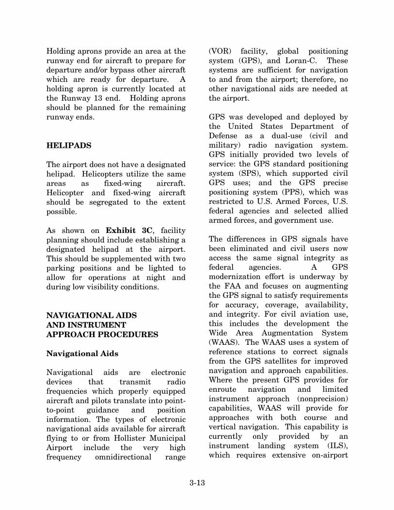
A review of Appendix 16 indicates that Runway 13-31 can support an APV with visibility minimums of one mile and cloud ceilings as low as 300 feet. Lower visibility and cloud ceiling minimums would require an approach lighting system, upgraded runway edge lighting, and precision runway markings. These lighting and marking improvements will be detailed later within this chapter. LIGHTING AND MARKING Currently, there are a number of lighting and pavement marking aids serving pilots using Hollister Municipal Airport. These lighting systems and marking aids assist pilots in locating the airport at night or in poor weather conditions and assist in the ground movement of aircraft. Existing and future lighting and marking aids are summarized on Exhibit 3D. Identification Lighting Hollister Municipal Airport is equipped with a rotating beacon to assist pilots in locating the airport at night. The existing rotating beacon, located next to the electrical vault southeast of the runway intersection, is being replaced and should be maintained in the future.

3-16
Runway and Taxiway Lighting Runways 13-31 and 6-24 are equipped with medium intensity runway lights (MIRL). The runways are also equipped with threshold lights, which indicate the location of the runway threshold at night. The MIRL to Runway 6-24 are sufficient for the use of this runway and should be maintained through the planning period. High intensity runway lighting (HIRL) is needed for a future precision approach to Runway 13-31. Effective ground movement of aircraft at night can be enhanced by taxiway lighting. Currently, taxiways at Hollister Municipal airport are equipped with retro-reflector markers. Facility planning should include the installment of medium intensity taxiway lighting (MITL) along all taxiways at the airport. Visual Approach Lighting The landing phase of all flights to the airport must be conducted visually. To provide pilots with visual descent information during landings to the runway, visual glideslope indicators are commonly provided at airports. A precision approach path indicator (PAPI-2L) is installed at the Runways 13 and 31 ends for this purpose. A visual approach slope indicator (VASI) is installed to Runway 24. While the PAPI-2L is appropriate for the existing mix of aircraft using the airport, a PAPI-4L should ultimate be planned for Runways 13 and 31. The
PAPI-4L is more appropriate for business jet operations. The Runway 24 VASI should ultimately be replaced with the more cost-efficient PAPI-2L. A PAPI-2L should be planned for Runway 6. Approach and Runway End Identification Lighting Runway end identification lighting provides the pilot with rapid and positive identification of the runway end. The most basic system involves runway end identifier lights (REILs). As REILs provide pilots with the ability to identify the runway ends and distinguish the runway end lighting from other lighting on the airport and in the approach areas, REILs are installed at the Runway 24, 13, and 31 ends. A REIL should be planned for Runway 6. The REILs to Runway 13 and Runway 24 should be maintained through the planning period. To support a precision approach to Runway 31, the existing Runway 31 REIL should ultimately be replaced with a medium intensity approach lighting system with runway alignment indicator lights (MALSR). Airfield Signs Lighted directional and hold signs are installed at the airport. This signage identifies runways, taxiways, and apron areas. These aid pilots in determining their position on the airport and provide directions to their desired location on the airport. These lighting aids are sufficient and should
01M
P12
-3D
-12/
11/0
3
SHORT TERM NEED LONG TERM NEEDEXISTING
Straight-in or Circling GPS Approach - Runway 31One mile visibility, 600' cloud ceiling minimums
Approach Categories A and B11/2 mile visibility, 600' cloud ceiling minimums
Approach Categories CAdd Approach Category D
Precision Approach - Runway 31 Approach Categories A, B, C, and DOne-half mile visibility minimum
200' cloud ceilings
APV - Runway 13 Approach Categories A, B, C, and D
One mile visibility minimum
Straight-in or Circling GPS Approach - Runway 31One mile visibility, 600' cloud ceiling minimums
Approach Categories A and B11/2 mile visibility, 600' cloud ceiling minimums
Approach Categories C
INSTRUMENT APPROACH PROCEDURES
Rotating BeaconPilot Controlled Lighting
Rotating BeaconPilot Controlled Lighting
Rotating BeaconPilot Controlled Lighting
AIRFIELD LIGHTING AND MARKINGS
Medium Intensity Runway Edge Lighting
Lighted Runway/Taxiway Directional Signage
PAPI-2 - Runway 13 and 31
REIL - Runway 13 and 31
Nonprecision Runway Markings
Medium Intensity Taxiway Edge Lighting
High Intensity Runway Edge Lighting
Lighted Runway/Taxiway Directional Signage
PAPI-4 - Runway 13 and 31
REIL - Runway 13MALSR - Runway 13
Distance Remaining Signs
Precision Runway Markings
Medium Intensity Taxiway Edge Lighting
Medium Intensity Runway Edge Lighting
Lighted Runway/Taxiway Directional Signage
PAPI-2 - Runway 13 and 31
REIL - Runway 13 and 31
Nonprecision Runway Markings
Taxiway Edge Reflectors
Runway 13-31
Medium Intensity Runway Edge Lighting
PAPI-2 - Runway 6 and 24
Lighted Runway/Taxiway Directional Signage
REILs - Runways 6 and 24
Medium Intensity Taxiway Edge Lighting
Basic Runway Markings
Medium Intensity Runway Edge Lighting
PAPI-2 Runway 6 and 24
Lighted Runway/Taxiway Directional Signage
REILs - Runways 6 and 24
Medium Intensity Taxiway Edge Lighting
Basic Runway Markings
Medium Intensity Runway Edge Lighting
VASI-4 - Runway 24
Lighted Runway/Taxiway Directional Signage
REIL - Runway 24
Taxiway Edge Reflectors
Basic Runway Markings
Runway 13-31
Lighted Wind Indicator
Segmented Circle
Automated Weather Observation System (AWOS)
Remote Communications Outlet (RCO)
UNICOM
Lighted Wind Indicator
Segmented Circle
Automated Weather Observation System (AWOS)
Remote Communications Outlet (RCO)
UNICOM
Lighted Wind Indicator
Segmented Circle
Tetrahedron
Remote Communications Outlet (RCO)
UNICOM
WEATHER/COMMUNICATION FACILITIES
HollisterMunicipalAirportExhibit 3D
AIRFIELD SUPPORT REQUIREMENTS
APV - Approach with Vertical GuidanceGPS - Global Positioning SystemMALSR - Medium Intensity Approach Lighting System with runway alignment indicator lighting
PAPI - Precision Approach Path IndicatorREIL - Runway End Identifier LightsVASI - Visual Approach Slope Indicator
KEY:

3-17
be maintained through the planning period. Pilot-Controlled Lighting Hollister Municipal Airport is equipped with pilot-controlled lighting (PCL). PCL allows pilots to control the intensity of runway and taxiway lighting using the radio transmitter in the aircraft. PCL also provides for more efficient use of runway and taxiway lighting energy use. A PCL system turns the runway or taxiway lights off or to a lower intensity when not in use. Similar to changing the intensity of the lights, pilots can turn up the lights using the radio transmitter in the aircraft. This system should be maintained through the planning period. All airfield lighting components should be connected to this system. Distance Remaining Signs Distance remaining signage should be planned for Runway 13-31. These lighted signs are placed in 1,000-foot increments along the runway to notify pilots of the length of runway remaining. Pavement Markings Pavement markings are designed according to the type of instrument approach available on the runway. FAA AC 150/5340-1F, Markings of Paved Areas on Airports, provides the guidance necessary to design an
airport’s markings. Runway 13-31 is equipped with nonprecision runway markings. Runway 6-24 is equipped with basic runway markings. To support the future precision approach to Runway 31, precision runway markings to Runway 31 will be required. The remaining makings will be sufficient through the panning period. Taxiway and apron areas also require marking to assure that aircraft remain on the pavement. Yellow centerline stripes are currently painted on all taxiway and apron surfaces at the airport to provide this guidance to pilots. Besides routine maintenance, these markings will be sufficient through the planning period. WEATHER REPORTING To provide weather reporting, an automated weather observation system (AWOS) or automated surface observation system (ASOS) is commonly installed at an airport. Both systems provide similar capabilities which include reporting current weather conditions such as: altimeter setting, wind direction and speed, temperature, dewpoint, density altitude, visibility, cloud ceilings data, and precipitation identification and intensity. Hollister Municipal Airport is not currently equipped with automated weather reporters. However, the City has a federal grant to install an AWOS. This will provide pilots flying into or out of the airport more accurate information about weather conditions in the area.

3-18
OTHER FACILITIES The airport has a lighted wind cone which provides pilots with information about wind conditions. A segmented circle provides traffic pattern information to pilots. These facilities are required when the airport is not served by a 24-hour airport traffic control tower (ATCT). Hollister Municipal Airport is also equipped with a tetrahedron which also indicates wind direction. These facilities are sufficient and should be maintained in the future. AIRPORT TRAFFIC CONTROL TOWER Hollister Municipal Airport does not have an operational ATCT; therefore, no formal terminal air traffic control
services are available at the airport. The establishment of a fully-funded ATCT, staffed and maintained by FAA personnel, follows guidance provided in FAA Handbook 7031.2C, Airway Planning Standard Number One - Terminal Air Navigation Facilities and Air Traffic Control Services. To be identified as a possible candidate for an ATCT, the airport must meet certain qualifications concerning the activity of operations within six categories: Air Carrier Operations, Air Taxi Operations, General Aviation Itinerant Operations, General Aviation Local Operations, Military Itinerant Operations, and Military Local Operations. To be identified as a possible candidate for an ATCT, the sum of the following formula must be greater than or equal to one. The formula is as follows:
AC +
AT +
GAI +
GAL +
MI +
ML =
X
38,000
90,000
160,000
280,000
48,000
90,000
Where:
AC = Air Carrier Operations AT = Air Taxi Operations GAI = General Aviation Itinerant Operations GAL = General Aviation Local Operations MI = Military Itinerant Operations ML = Military Local Operations
Using current activity levels and those forecast activity levels prepared in Chapter Two, it is expected that Hollister Municipal Airport would not qualify as a possible candidate for a fully-funded FAA ATCT due to levels of air traffic at the airport. At 2002
activity levels, the sum of the formula above is 0.29. At long term planning horizon levels, the sum is 0.66. A remote communications outlet (RCO) is commonly established at an

3-19
airport that has an instrument approach procedure. The RCO provides pilots with a direct connection to the Air Route Traffic Control Center (ARTCC) for retaining communication with NorCal Approach and Oakland Center. Oakland Center is available via an antenna located on the airport. A RCO should be included in facility planning for the airport. AIRFIELD CONCLUSIONS The critical design aircraft currently falls within ARC B-II. In the future, it is expected that the critical design aircraft will fall within ARC C-II. This places new airfield design requirements on the airport, including a runway/taxiway separation of 400 feet and larger safety areas for Runway 13-31. The alternatives analysis will examine the options available to conform to these standards. An ultimate runway length for Runway 13-31 of 7,000 feet should be examined. This would better serve business jet operators at the airport which are weight-limited, especially during warm summer months. Converting a portion of the lead-in taxiway to Runway 24 may provide the ability to meet this length. Additional length is not required to Runway 6-24, although consideration needs to be given to the use of the lead-in taxiways at each end of the runway.
Additional exit taxiways should be planned for each runway along with options to reconfigure the Runway 6 and Runway 24 entrance taxiways perpendicular to the runway. A parallel taxiway should be planned west of Runway 13-31 and north of Runway 6-24 to facilitate future landside development in these areas. Holding aprons should be planned for the Runway 31, 6, and 24 ends. Specially-planned taxiways should be planned for glider aircraft handling. A helipad should ultimately be constructed to enhance aircraft safety and operations on the ground by segregating helicopter and fixed-wing aircraft. In order to provide for aircraft arrivals at lower decision height, a precision approach should be planned for Runway 31, and an APV should be planned for Runway 13. This will require the installation of a MALSR to Runway 31, precision runway markings to Runway 31, and HIRL. The existing Runway 13 and Runway 31 PAPI-2L should be upgraded to PAPI-4L. The Runway 24 VASI should be replaced with a PAPI-2. A PAPI-2 and REIL should be planned for Runway 6. All the taxiways should be equipped with MITL. Distance remaining signs should be planned for Runway 13-31. The addition of an automated weather reporting system would enable local and transient pilots to determine weather conditions at the airport.

3-20
LANDSIDE REQUIREMENTS Landside facilities are those necessary for handling of aircraft and passengers while on the ground. These facilities provide the essential interface between the air and ground transport-ation modes. The capacities of the various components of each area were examined in relation to projected demand to identify future landside facility needs. HANGAR REQUIREMENTS Utilization of hangar space varies as a function of local climate, security, and owner preferences. The trend in general aviation aircraft, whether single or multi-engine, is towards more sophisticated aircraft (and, consequently, more expensive aircraft). Additionally, at airports such as Hollister Municipal Airport, where a large number of vintage and sport aircraft are based, the aircraft owners prefer enclosed storage to protect those aircraft which may have fabric covered surfaces. Therefore, many aircraft owners prefer enclosed hangar space to outside tie-downs. Presently, all the hangars at the airport are occupied. The demand for aircraft storage hangars is dependant upon the number and type of aircraft expected to base at the airport in the future. For planning purposes, it is necessary to estimate hangar requirements
based upon actual demand trends and financial investment conditions. While a majority of aircraft owners prefer enclosed aircraft storage, a number of based aircraft will still tie-down outside (due to the lack of hangar availability, hangar rental rates, and/or operational needs). Therefore, enclosed hangar facilities should not be planned for each aircraft. Currently, 125 of the 195 based aircraft are stored in enclosed hangars at Hollister Municipal Airport. Future hangar requirements for the airport are summarized on Exhibit 3E. Future hangar requirements were developed with the assumption that a majority of aircraft owners would prefer enclosed storage and that the percentage of aircraft within enclosed hangar facilities would increase through the planning period. T-hangar requirements were determined by providing 1,066 square feet of space for aircraft within T-hangars, 1,200 square feet for single engine aircraft stored in conventional hangars, and 2,500 square feet for multi-engine aircraft within conventional hangars. There are 32 aircraft owners on a hangar waiting list maintained by Gavilan Aviation. This list includes aircraft owners who currently base an aircraft at Hollister Municipal Airport and those who base their aircraft at another regional airport. This list indicates that there is currently an unmet demand for hangar storage at Hollister Municipal Airport and that additional T-hangar storage could be constructed at the airport.

01M
P12
-3E
-12/
12/0
3
Exhibit 3ELANDSIDE FACILITY REQUIREMENTS
AIRCRAFT STORAGE HANGARAIRCRAFT STORAGE HANGARREQUIREMENTSREQUIREMENTSAIRCRAFT STORAGE HANGARREQUIREMENTS
HANGAR AREA REQUIREMENTSHANGAR AREA REQUIREMENTSHANGAR AREA REQUIREMENTS
AIRCRAFT PARKING APRONAIRCRAFT PARKING APRONREQUIREMENTSREQUIREMENTSAIRCRAFT PARKING APRONREQUIREMENTS
FUEL STORAGE (gallons)FUEL STORAGE (gallons)FUEL STORAGE (gallons)
300 188 112
Aircraft to be HangaredT-Hangars / Shade HangarsConventional Hangar Positions
125 75
28-59
182 111 71
146 95 51
220 136 84
T-Hangar Area (s.f.)Conventional Hangar Storage Area Maintenance AreaSubtotal Conventional AreaTotal Hangar Area (s.f.)
81,600 71,500
-- 71,500
153,100
120,800 119,000 17,900
136,900 257,700
103,400 88,500 13,300
101,800 205,200
148,000 138,500 20,800
159,300 307,300
204,500 181,200 27,200
208,400 412,900
TRANSIENT PASSENGERTRANSIENT PASSENGERTERMINAL FACILITIESTERMINAL FACILITIESTRANSIENT PASSENGERTERMINAL FACILITIES
46 36,600
3 4,800
80 40,000
129 81,400
Single, Multi-Engine Transient Aircraft Positions Apron Area (s.y.)Transient Business Jet Positions Apron Area (s.y.)Locally-Based Aircraft Positions Apron Area (s.y.)Total PositionsTotal Apron Area (s.y.)
120 42,800
26 20,600
2 3,200
56 28,000
84 51,800
19 15,500
2 3,200
70 35,000
91 53,700
32 25,700
2 3,200
64 32,000
98 60,900
Building Area 3,600Note 1 4,680 5,760
LONG TERMNEED
EXISTING SHORT TERMNEED
CURRENTNEED
INTERMEDIATETERM NEED
OTHER FACILITIESOTHER FACILITIESOTHER FACILITIES
100LL AVGAS
JET-A
10,000
10,000
10,000
10,000
10,000
10,500
10,000
13,000
10,000
17,500
LONG TERMNEED
EXISTING SHORT TERMNEED
CURRENTNEED
INTERMEDIATETERM NEED
LONG TERMNEED
EXISTING SHORT TERMNEED
CURRENTNEED
INTERMEDIATETERM NEED
LONG TERMNEED
EXISTING SHORT TERMNEED
CURRENTNEED
INTERMEDIATETERM NEED
LONG TERMNEED
EXISTING SHORT TERMNEED
CURRENTNEED
INTERMEDIATETERM NEED
LONG TERMNEED
EXISTING SHORT TERMNEED
CURRENTNEED
INTERMEDIATETERM NEED
Aircraft WashRack
Aircraft WashRack
Aircraft WashRack
Aircraft WashRack
Aircraft WashRack
Note 1 - Transient terminal facility needs provided in privately owned hangars.

3-21
While all 32 aircraft owners desire hangar space, their decision to occupy a hangar will be based primarily on the hangar rental rate. If the rate is too high, they will choose not to base at the airport. Other factors include their current aircraft situation. For some owners, it may have been up to a year since they had been put on the list and they may have sold their aircraft or found other hangar space. For these reasons and others, a hangar waiting list does represent the absolute demand for hangar facilities. Therefore, it should not be expected that 32 hangars could be constructed and filled. The members of the Planning Advisory Committee (PAC) felt that an additional 20 T-hangars could be constructed and filled at the airport. This has been shown in the Current Need section of Exhibit 3E. As indicated on the exhibit, additional hangar space is expected to be required through the planning period. It is expected that the aircraft storage hangar requirements will continue to be met through a combination of hangar types. The alternatives analysis will examine the options available for hangar development at the airport and determine the best location for each type of hangar facility. AIRCRAFT PARKING APRON REQUIREMENTS The aircraft parking apron should provide for at least the number of locally-based aircraft that are not
stored in hangars, as well as transient aircraft. There are approximately 120 tie-downs available for both based and transient aircraft on a single apron at the airport. Although the majority of future based aircraft were assumed to be stored in an enclosed hangar, a number of based aircraft will still tie-down outside. Glider aircraft are currently stored on an unpaved area northeast of the Runway 13-31/Runway 6-24 intersection. Ideally, a paved area should be available for these aircraft for year-round all-weather use. Along with based aircraft parking needs, transient aircraft parking needs must also be considered in determining apron requirements. Hollister Municipal Airport accommodates a significant level transient activity annually. Total apron area requirements were determined by applying a planning criterion of 800 square yards per transient aircraft parking position and 500 square yards for each locally-based aircraft parking position. Transient business jet positions were determined by applying a planning criterion of 1,600 square yards for each transient business jet position. The results of this analysis are presented on Exhibit 3E. Based upon the planning criteria above and assumed transient and based aircraft users, additional apron areas will be needed through the planning period. Additional apron area in excess of these needs may be needed as new hangar areas are developed on the

3-22
airport which is not contiguous with the existing apron areas. TERMINAL BUILDING REQUIREMENTS General aviation terminal facilities provide an area for transient passengers to meet waiting passengers, pilots’ lounge and flight planning, concessions, management, storage, restrooms, and general aviation businesses providing services such as refueling and line services. There is currently not a dedicated general aviation terminal building at the airport, although these services are provided in private buildings at the airport. Exhibit 3E summarizes the space requirements required to efficiently provide these services through the planning period. SUPPORT REQUIREMENTS Various facilities that do not logically fall within classifications of airfield, terminal building, or general aviation areas have been identified. These other areas provide certain functions related to the overall operation and safety of the airport and include: airport access, vehicle parking, fuel storage, and aircraft rescue and firefighting. Airport Access State Highways 25 and 156 provide primary highway access for the area.
Hollister Municipal Airport is accessed via 156 (San Felipe Road). Off Highway 156, a two-lane access road leads to the landside facilities providing access for based aircraft owners. These roadways provide sufficient capacity for the level of activity at the airport and will not require any upgrades to serve the airport. Fuel Storage Fuel storage at Hollister Municipal Airport totals 20,000 gallons, evenly split between 100LL and Jet-A fuel. Fuel is dispensed through the fixed fuel island and mobile fuel trucks. Exhibit 3E presents future Avgas and Jet-A storage requirements for the airport based upon the fuel use projections developed from the fuel delivered to the airport in 2001 and 2002. Fuel storage requirements are typically based upon maintaining a two-week supply of fuel during an average month, however, more frequent deliveries can reduce the fuel storage capacity requirement. Based upon the use assumptions presented above, it is anticipated that additional fuel storage will be needed through the planning period for Jet-A. Aircraft Wash Facility There is one aircraft wash facility located on the airport. It is near the west T-hangars. This wash rack is sufficient and should be maintained.
3-23
Perimeter Fencing and Access Gates The airport is presently equipped with a combination of barbed wire and chain link fencing; however, the entire perimeter of the airport and the apron areas are not fully equipped with sufficient fencing to prevent the inadvertent entry of vehicles or persons to the aircraft operating area. Facility planning should consider improving the current fencing to limit access to aircraft operating areas and secure the airport perimeter. The airport has a current FAA grant to improve fencing at the airport. Automated access gates should be considered for access to the aircraft operating areas. These systems are operated through a keypad or card system. This would allow the airport to control the vehicles which access the aircraft operational areas and prevent vehicles from inadvertently accessing these areas. Skydiving Operations While a business providing skydiving services is located on the airport, there is no dedicated drop zone on the airport. The drop zone has been arranged privately by the company on private property near Tres Pinos. F.A.R. Part 105, Parachute Operations, specifies the requirements
for skydiving operations. Section 105.23, Parachute Operations over or onto Airports, specifies that “for airports without an operating control tower, [no person may conduct parachute operations unless] prior approval has been obtained from the management of the airport to conduct parachute operations over or on that airport.” The City of Hollister has not approved skydiving activities on the airport. The United States Parachute Association guidance for the size of the drop zone (landing area) is shown on Table 3F. These criterion should be considered if a drop zone is contemplated at the airport. However, as established previously, the City of Hollister must provide approval to conduct parachute operations at the airport. SUMMARY The intent of this chapter has been to outline the facilities required to meet potential aviation demands projected for Hollister Municipal Airport through the long term planning horizon. The next step is to develop a direction for development to best meet these projected needs. The remainder of the master plan will be devoted to outlining this direction, its schedule, and costs.

3-24
TABLE 3F Drop Zone Requirements United States Parachute Association 1. Areas used for skydiving should be unobstructed, with the following minimum
radial distances to the nearest hazard: [S] a. solo students and A-license holders – 100 meters (328.084’) b. B- and C-license holders – 50 meters (164.0421’) c. D-license holders – unlimited 2. Hazards are defined as telephone and power lines, towers, buildings, open
bodies of water, highways, automobiles, and clusters of trees covering more than 3,000 square meters. [NW]
3. Manned ground-to-air communications (e.g., radios, panels, smoke, lights) are
to be present on the drop zone during skydiving operations. [NW]


![chapter31 section01 edit REPTILES MODIFIED.ppt ... - Biology · Title: Microsoft PowerPoint - chapter31_section01_edit REPTILES MODIFIED.ppt [Mode de compatibilité] Author: Ari Created](https://img.pdfslide.us/doc/110x75/5b5f676b7f8b9a6d448e13e9/chapter31-section01-edit-reptiles-biology-title-microsoft-powerpoint.jpg)
![Chapter 31. Current and Resistance Chapter …physics.gsu.edu/dhamala/Phys2212/Slides/Chapter31.pdfTitle Microsoft PowerPoint - Chapter31 [Compatibility Mode] Author dhamala Created](https://img.pdfslide.us/doc/110x75/5ab11dc57f8b9aea528bfe74/chapter-31-current-and-resistance-chapter-microsoft-powerpoint-chapter31.jpg)