Embed Size (px)
Citation preview
1
Chapter 17
pnpn and Other Devices© Modified by Yuttapong Jiraraksopakun
ENE, KMUTT 2009
Copyright ©2009 by Pearson Education, Inc.
Upper Saddle River, New Jersey 07458 • All rights reserved.
Electronic Devices and Circuit Theory, 10/e
Robert L. Boylestad and Louis Nashelsky
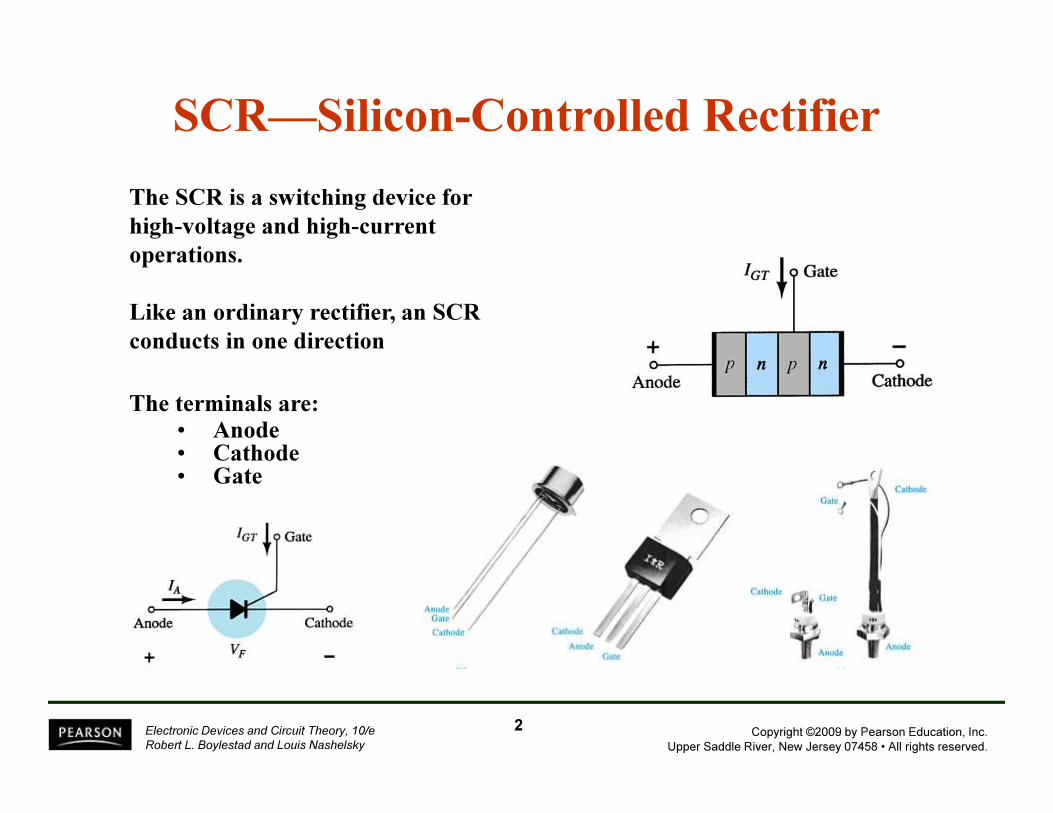
SCR—Silicon-Controlled Rectifier
The SCR is a switching device for
high-voltage and high-current
operations.
Like an ordinary rectifier, an SCR
conducts in one direction
The terminals are:• Anode• Cathode• Gate
2
Copyright ©2009 by Pearson Education, Inc.
Upper Saddle River, New Jersey 07458 • All rights reserved.
Electronic Devices and Circuit Theory, 10/e
Robert L. Boylestad and Louis Nashelsky
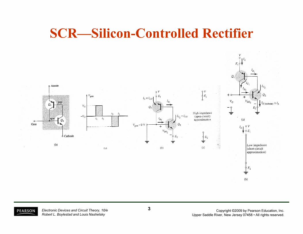
SCR—Silicon-Controlled Rectifier
3
Copyright ©2009 by Pearson Education, Inc.
Upper Saddle River, New Jersey 07458 • All rights reserved.
Electronic Devices and Circuit Theory, 10/e
Robert L. Boylestad and Louis Nashelsky
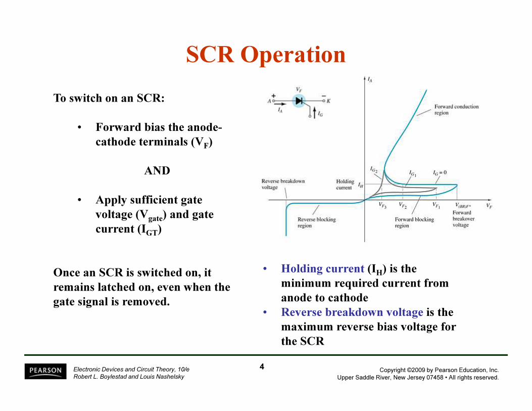
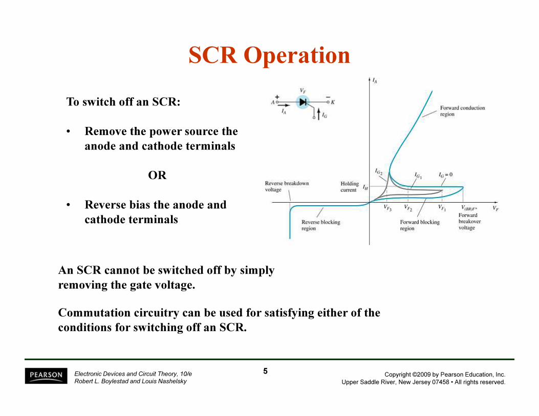
SCR Operation
Once an SCR is switched on, it
remains latched on, even when the
gate signal is removed.
• Holding current (IH) is the
minimum required current from
anode to cathode
• Reverse breakdown voltage is the
maximum reverse bias voltage for
the SCR
To switch on an SCR:
• Forward bias the anode-
cathode terminals (VF)
AND
• Apply sufficient gate
voltage (Vgate) and gate
current (IGT)
4
Copyright ©2009 by Pearson Education, Inc.
Upper Saddle River, New Jersey 07458 • All rights reserved.
Electronic Devices and Circuit Theory, 10/e
Robert L. Boylestad and Louis Nashelsky
To switch off an SCR:
• Remove the power source the
anode and cathode terminals
OR
• Reverse bias the anode and
cathode terminals
SCR Operation
An SCR cannot be switched off by simply
removing the gate voltage.
Commutation circuitry can be used for satisfying either of the
conditions for switching off an SCR.
5
Copyright ©2009 by Pearson Education, Inc.
Upper Saddle River, New Jersey 07458 • All rights reserved.
Electronic Devices and Circuit Theory, 10/e
Robert L. Boylestad and Louis Nashelsky
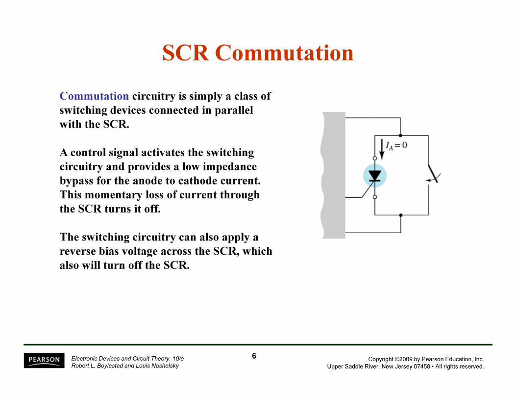
Commutation circuitry is simply a class of
switching devices connected in parallel
with the SCR.
A control signal activates the switching
circuitry and provides a low impedance
bypass for the anode to cathode current.
This momentary loss of current through
the SCR turns it off.
The switching circuitry can also apply a
reverse bias voltage across the SCR, which
also will turn off the SCR.
SCR Commutation
6
Copyright ©2009 by Pearson Education, Inc.
Upper Saddle River, New Jersey 07458 • All rights reserved.
Electronic Devices and Circuit Theory, 10/e
Robert L. Boylestad and Louis Nashelsky
SCR False Triggering
An SCR can be forced to trigger conduction under several
conditions that must be avoided:
• Excessively high voltage from anode to
cathode
• High frequency signal from gate to
cathode
• High operating temperature
7
Copyright ©2009 by Pearson Education, Inc.
Upper Saddle River, New Jersey 07458 • All rights reserved.
Electronic Devices and Circuit Theory, 10/e
Robert L. Boylestad and Louis Nashelsky
SCR Applications
In these applications the SCR gate circuit is used to
monitor a situation and trigger the SCR to turn on
a portion of the circuit.
• SCR phase control
• Battery-charging regulator
• Temperature controller circuit
• Emergency-lighting system
8
Copyright ©2009 by Pearson Education, Inc.
Upper Saddle River, New Jersey 07458 • All rights reserved.
Electronic Devices and Circuit Theory, 10/e
Robert L. Boylestad and Louis Nashelsky
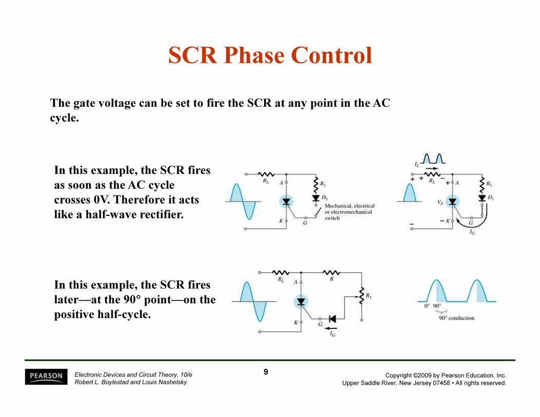
The gate voltage can be set to fire the SCR at any point in the AC
cycle.
SCR Phase Control
In this example, the SCR fires
as soon as the AC cycle
crosses 0V. Therefore it acts
like a half-wave rectifier.
In this example, the SCR fires
later—at the 90° point—on the
positive half-cycle.
9
Copyright ©2009 by Pearson Education, Inc.
Upper Saddle River, New Jersey 07458 • All rights reserved.
Electronic Devices and Circuit Theory, 10/e
Robert L. Boylestad and Louis Nashelsky
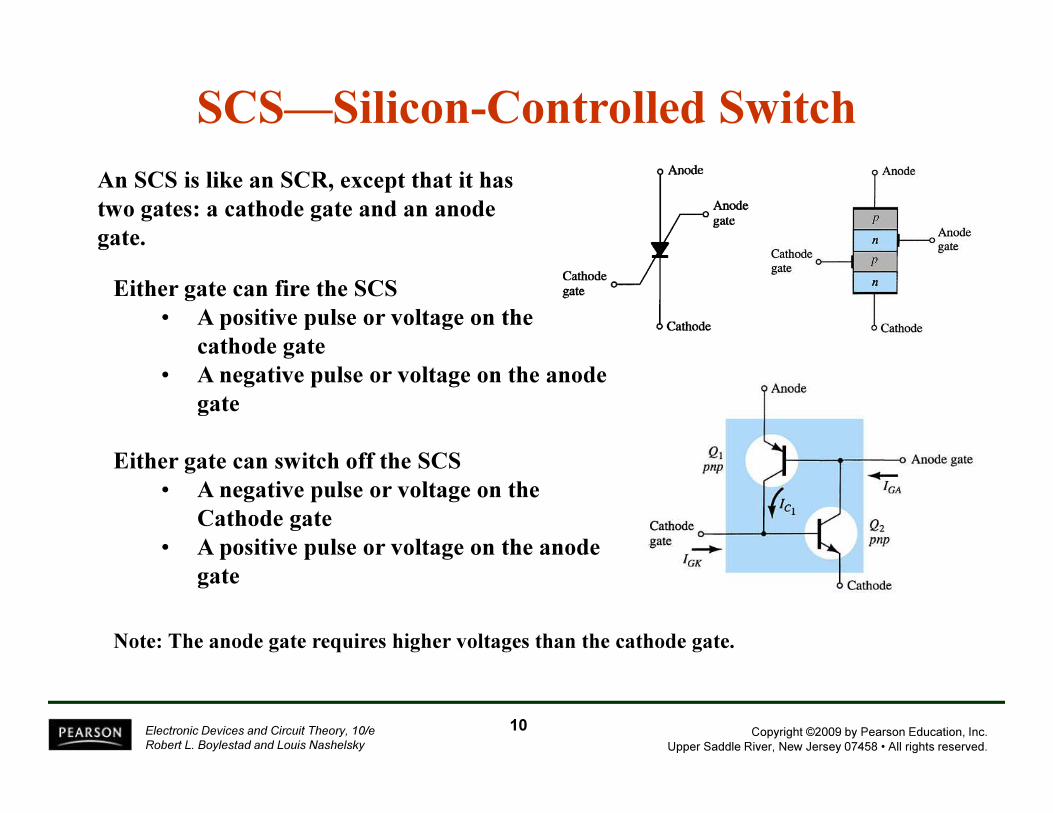
SCS—Silicon-Controlled Switch
An SCS is like an SCR, except that it has
two gates: a cathode gate and an anode
gate.
Either gate can fire the SCS
• A positive pulse or voltage on the
cathode gate
• A negative pulse or voltage on the anode
gate
Either gate can switch off the SCS
• A negative pulse or voltage on the
Cathode gate
• A positive pulse or voltage on the anode
gate
Note: The anode gate requires higher voltages than the cathode gate.
10
Copyright ©2009 by Pearson Education, Inc.
Upper Saddle River, New Jersey 07458 • All rights reserved.
Electronic Devices and Circuit Theory, 10/e
Robert L. Boylestad and Louis Nashelsky
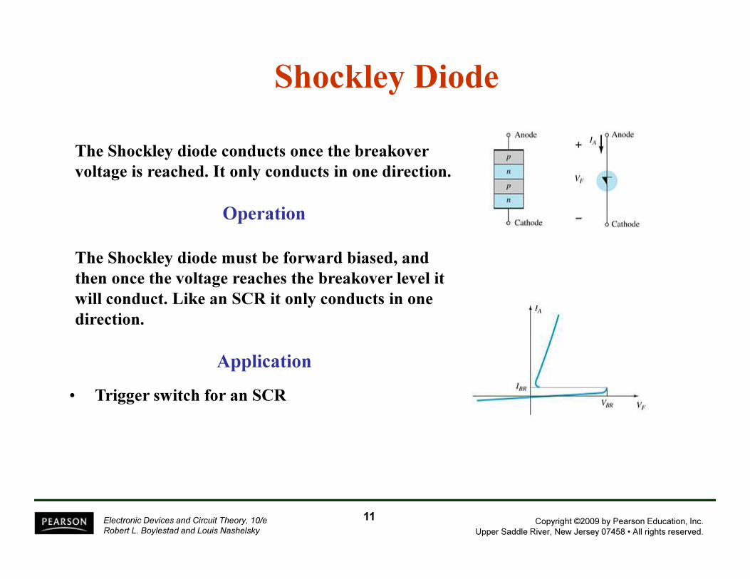
Shockley Diode
The Shockley diode conducts once the breakover
voltage is reached. It only conducts in one direction.
Operation
The Shockley diode must be forward biased, and
then once the voltage reaches the breakover level it
will conduct. Like an SCR it only conducts in one
direction.
Application
• Trigger switch for an SCR
11
Copyright ©2009 by Pearson Education, Inc.
Upper Saddle River, New Jersey 07458 • All rights reserved.
Electronic Devices and Circuit Theory, 10/e
Robert L. Boylestad and Louis Nashelsky
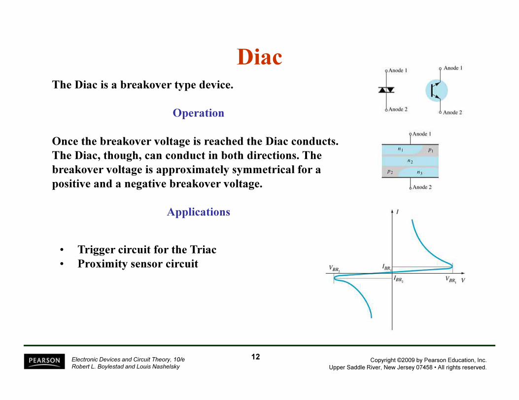
DiacThe Diac is a breakover type device.
Operation
Once the breakover voltage is reached the Diac conducts.
The Diac, though, can conduct in both directions. The
breakover voltage is approximately symmetrical for a
positive and a negative breakover voltage.
Applications
• Trigger circuit for the Triac
• Proximity sensor circuit
12
Copyright ©2009 by Pearson Education, Inc.
Upper Saddle River, New Jersey 07458 • All rights reserved.
Electronic Devices and Circuit Theory, 10/e
Robert L. Boylestad and Louis Nashelsky
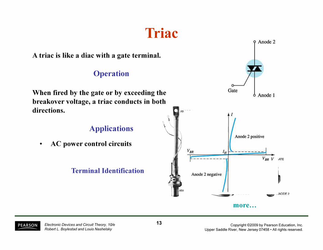
Terminal Identification
A triac is like a diac with a gate terminal.
Operation
When fired by the gate or by exceeding the
breakover voltage, a triac conducts in both
directions.
Applications
Triac
• AC power control circuits
more…
13
Copyright ©2009 by Pearson Education, Inc.
Upper Saddle River, New Jersey 07458 • All rights reserved.
Electronic Devices and Circuit Theory, 10/e
Robert L. Boylestad and Louis Nashelsky
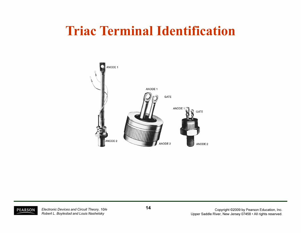
Triac Terminal Identification
14
Copyright ©2009 by Pearson Education, Inc.
Upper Saddle River, New Jersey 07458 • All rights reserved.
Electronic Devices and Circuit Theory, 10/e
Robert L. Boylestad and Louis Nashelsky
15
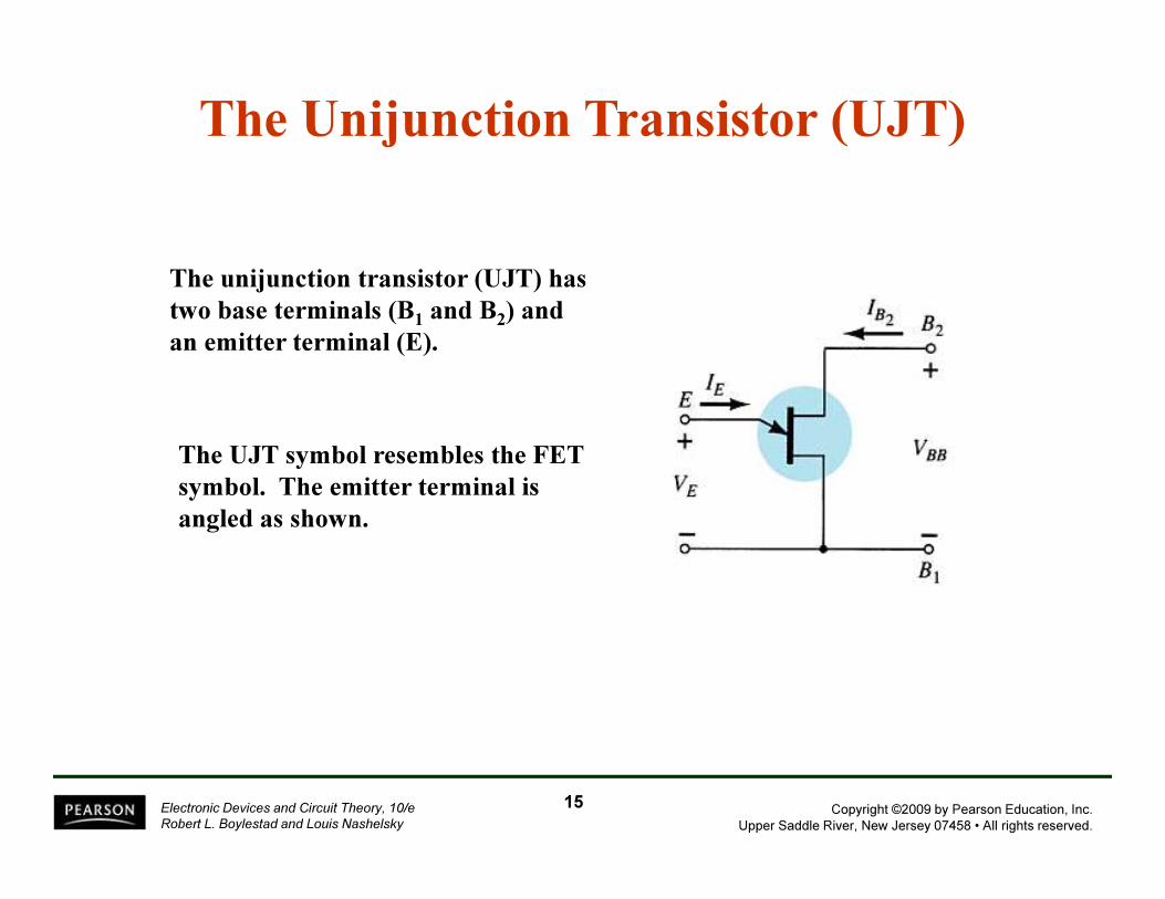
The Unijunction Transistor (UJT)
The unijunction transistor (UJT) has
two base terminals (B1 and B2) and
an emitter terminal (E).
The UJT symbol resembles the FET
symbol. The emitter terminal is
angled as shown.
Copyright ©2009 by Pearson Education, Inc.
Upper Saddle River, New Jersey 07458 • All rights reserved.
Electronic Devices and Circuit Theory, 10/e
Robert L. Boylestad and Louis Nashelsky
16
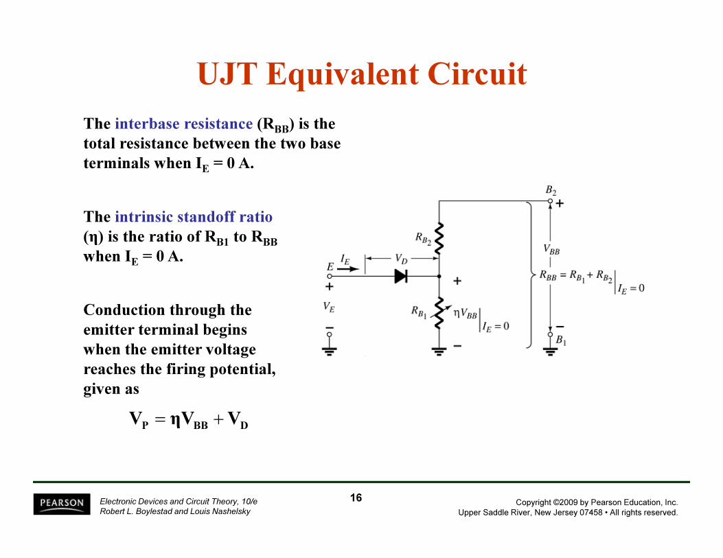
The interbase resistance (RBB) is the
total resistance between the two base
terminals when IE = 0 A.
UJT Equivalent Circuit
The intrinsic standoff ratio
(η) is the ratio of RB1 to RBB
when IE = 0 A.
Conduction through the
emitter terminal begins
when the emitter voltage
reaches the firing potential,
given as
DBBPVηVV +=
Copyright ©2009 by Pearson Education, Inc.
Upper Saddle River, New Jersey 07458 • All rights reserved.
Electronic Devices and Circuit Theory, 10/e
Robert L. Boylestad and Louis Nashelsky
17
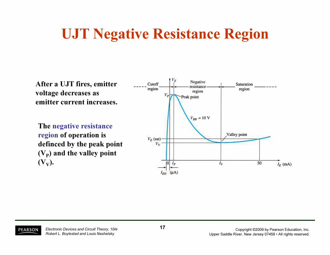
UJT Negative Resistance Region
After a UJT fires, emitter
voltage decreases as
emitter current increases.
The negative resistance
region of operation is
definced by the peak point
(VP) and the valley point
(VV).
Copyright ©2009 by Pearson Education, Inc.
Upper Saddle River, New Jersey 07458 • All rights reserved.
Electronic Devices and Circuit Theory, 10/e
Robert L. Boylestad and Louis Nashelsky
18
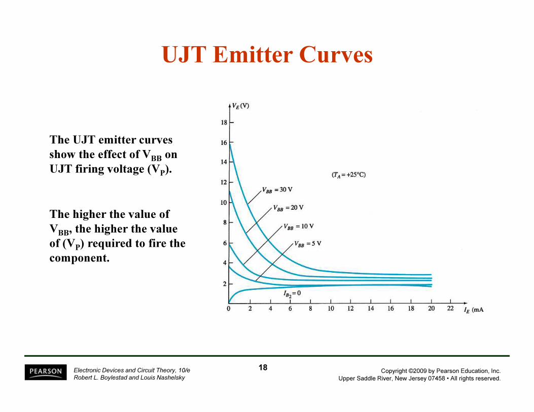
UJT Emitter Curves
The UJT emitter curves
show the effect of VBB on
UJT firing voltage (VP).
The higher the value of
VBB, the higher the value
of (VP) required to fire the
component.
Copyright ©2009 by Pearson Education, Inc.
Upper Saddle River, New Jersey 07458 • All rights reserved.
Electronic Devices and Circuit Theory, 10/e
Robert L. Boylestad and Louis Nashelsky
19
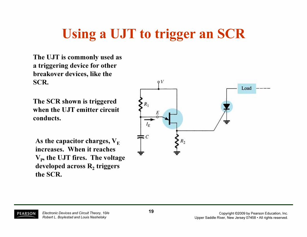
Using a UJT to trigger an SCR
The UJT is commonly used as
a triggering device for other
breakover devices, like the
SCR.
The SCR shown is triggered
when the UJT emitter circuit
conducts.
As the capacitor charges, VE
increases. When it reaches
VP, the UJT fires. The voltage
developed across R2 triggers
the SCR.
Copyright ©2009 by Pearson Education, Inc.
Upper Saddle River, New Jersey 07458 • All rights reserved.
Electronic Devices and Circuit Theory, 10/e
Robert L. Boylestad and Louis Nashelsky
20
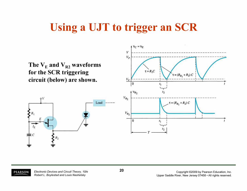
Using a UJT to trigger an SCR
The VE
and VR2
waveforms
for the SCR triggering
circuit (below) are shown.

Copyright ©2009 by Pearson Education, Inc.
Upper Saddle River, New Jersey 07458 • All rights reserved.
Electronic Devices and Circuit Theory, 10/e
Robert L. Boylestad and Louis Nashelsky
PUT—Programmable UJT
Characteristics
In some of its operating
characteristics, a PUT is more like
an SCR.
Like the UJT, the PUT has a
negative resistance region. But this
region is unstable in the PUT. The
PUT is operated between the on and
off states.
21
Copyright ©2009 by Pearson Education, Inc.
Upper Saddle River, New Jersey 07458 • All rights reserved.
Electronic Devices and Circuit Theory, 10/e
Robert L. Boylestad and Louis Nashelsky
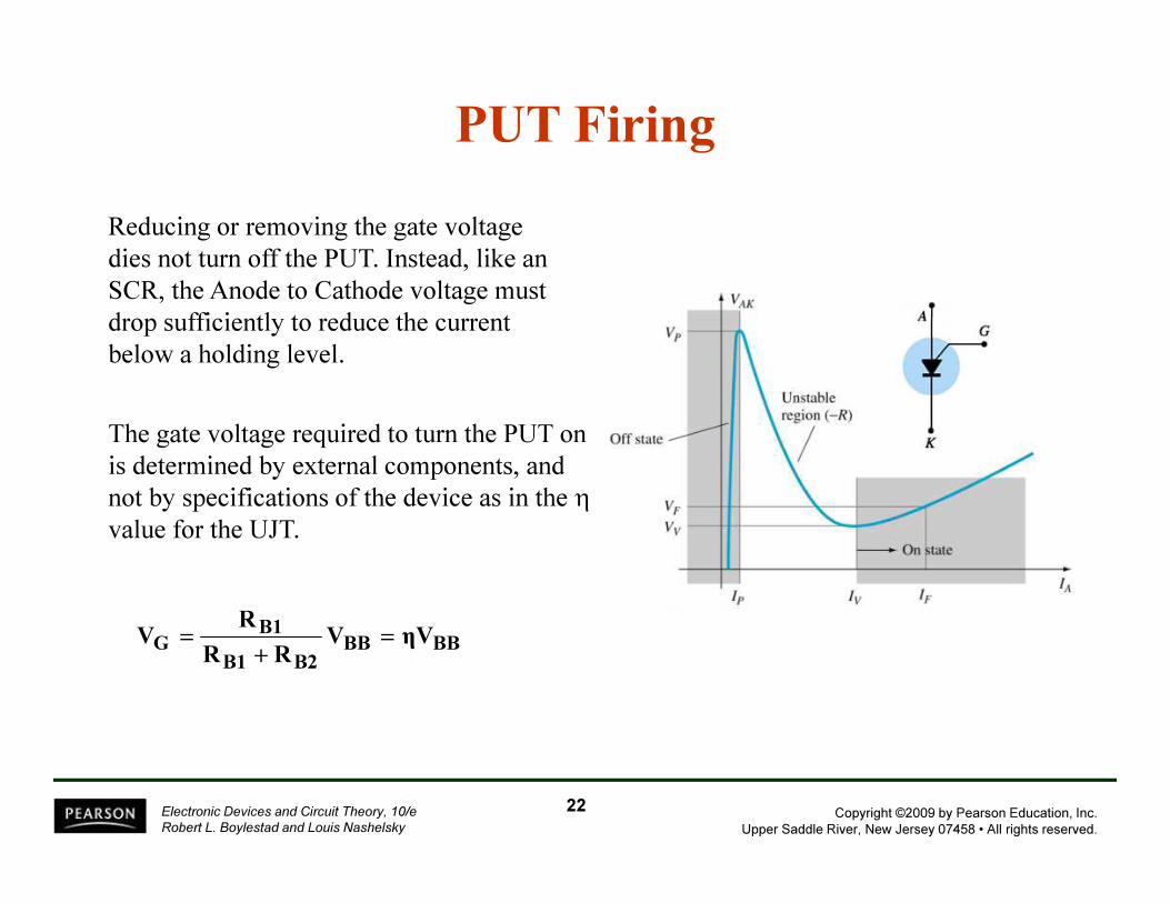
Reducing or removing the gate voltage
dies not turn off the PUT. Instead, like an
SCR, the Anode to Cathode voltage must
drop sufficiently to reduce the current
below a holding level.
The gate voltage required to turn the PUT on
is determined by external components, and
not by specifications of the device as in the η
value for the UJT.
BBBB
B2B1
B1G ηVV
RR
RV =
+
=
22
PUT Firing