Embed Size (px)
Citation preview

Chapter Nine
Fitting the Major Parts Together
Up to this point I have covered the work that goes into fabricating the three main parts of the harp - the neck, the pillar and sound box. This section explains how to join those parts together – an exciting part of the building process.
I will detail two of the methods I have used to join the neck and pillar to each other. Then I will outline the process of fitting and attaching the neck/pillar assembly to the sound box. Finally a template for strings will be positioned on the soundboard and the holes for the strings drilled through the string ribs. Many traditionalists use a mortise and tennon to join the neck to the pillar. To keep the neck from capsizing, the mortise has to be deep and fit tightly. For many designs, the shoulders of the tennon have to be cut along an angled curve, and it took me several hours, tears and some swearing to make a tight joint capable of withstanding prolonged strain.
I found two alternatives that were handsome and easy to make using tools common to most wood shops. I came across the doweled joint as I assembled one of the kit harps that Steve Green used to make. The double spline joint was my own invention.
Doweled Neck/Pillar JointThis joint is created by drilling three precisely spaced, parallel holes into the bottom of the neck and top of the pillar. In hard maple this requires a guide block, a 10” long 5/8” brad point drill bit (from Woodcraft) and a rugged drill motor.
Copyright 2005, Rick Kemper Chapter Nine, fitting the Major Parts Page 9.1

Copyright 2005, Rick Kemper Chapter Nine, fitting the Major Parts Page 9.2

The stress on the joint is asymmetrical - the dowel is not centered in the joint, it is offset to the side in tension, the side furthest away from the strings.
The first task is to create the jig – to drill three long parallel bores (holes) to guide the bit. It is a lot easier to make those bores if you start from the center with three perfectly straight, parallel “pilot holes” that are cut with a table saw.
(1) Three shallow kerfs are cut on the face along the length of a ¾” x 4” x 8” hardwood board, spaced one inch from each other.
(2) Another 4” x 8” board is glued onto the bottom of the first board. A thick clothes hanger wire can be run in and out of the kerf, pushing most of the glue out.
Copyright 2005, Rick Kemper Chapter Nine, fitting the Major Parts Page 9.3
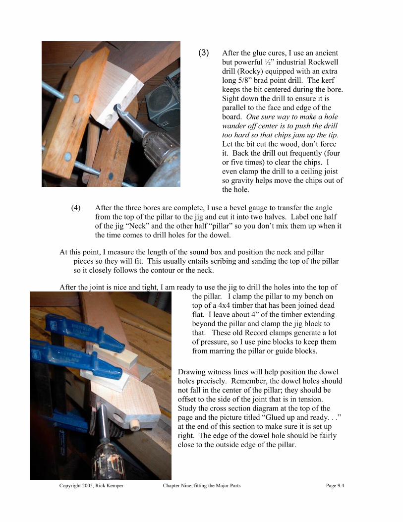
(3) After the glue cures, I use an ancient but powerful ½” industrial Rockwell drill (Rocky) equipped with an extra long 5/8” brad point drill. The kerf keeps the bit centered during the bore. Sight down the drill to ensure it is parallel to the face and edge of the board. One sure way to make a hole wander off center is to push the drill too hard so that chips jam up the tip. Let the bit cut the wood, don’t force it. Back the drill out frequently (four or five times) to clear the chips. I even clamp the drill to a ceiling joist so gravity helps move the chips out of the hole.
(4) After the three bores are complete, I use a bevel gauge to transfer the angle from the top of the pillar to the jig and cut it into two halves. Label one half of the jig “Neck” and the other half “pillar” so you don’t mix them up when it the time comes to drill holes for the dowel.
At this point, I measure the length of the sound box and position the neck and pillar pieces so they will fit. This usually entails scribing and sanding the top of the pillar so it closely follows the contour or the neck.
After the joint is nice and tight, I am ready to use the jig to drill the holes into the top of the pillar. I clamp the pillar to my bench on top of a 4x4 timber that has been joined dead flat. I leave about 4” of the timber extending beyond the pillar and clamp the jig block to that. These old Record clamps generate a lot of pressure, so I use pine blocks to keep them from marring the pillar or guide blocks.
Drawing witness lines will help position the dowel holes precisely. Remember, the dowel holes should not fall in the center of the pillar; they should be offset to the side of the joint that is in tension. Study the cross section diagram at the top of the page and the picture titled “Glued up and ready. . .” at the end of this section to make sure it is set up right. The edge of the dowel hole should be fairly close to the outside edge of the pillar.
Copyright 2005, Rick Kemper Chapter Nine, fitting the Major Parts Page 9.4

“Rocky” boring the second hole in the pillar
As you bore the hole, remember what makes bores wander off center. Take it slow, and back the drill out frequently to clear the chips.
The hole should be at least 2 ½” deep into the pillar. After the first hole is drilled, insert a 5/8” dowel to ensure the jig stays in place while drilling the next hole. The dowel should fit snuggly.
Drill the second hole and insert another dowel. Then drill the last hole. Repeat the process with the neck. In this photo you can see the witness line on the neck that I used to align with the edge of the drilling jig.
Repeat the process with the neck. In this photo you can see the witness line on the neck that I used to align with the edge of the drilling jig.
Then I cut three dowels and fit test the fit of the two pieces. Here one of the dowels is too long and needs to be cut shorter to allow the joint to close up.
Gotta have groovy dowels :The dowels need to have grooves cut into the sides to allow glue to escape during assembly. If the glue does not have an escape
Copyright 2005, Rick Kemper Chapter Nine, fitting the Major Parts Page 9.5

path, the dowel/hole turns into a little pneumatic cylinder that will either prevent the joint from closing or will split the neck or pillar. Here, three grooves are cut along the length of the dowels with a band saw, using a chunk of wood with a 5/8” hole in it. The grooves could also be cut on a table saw, router table, a V gouge or Dremel tool.
Assembly and Clamping
Whn clamping the neck and pillar, the two should be brought into compression with the clamping force centered over the dowels. This isn’t instantly achievable with most neck/pillar configurations. Take a few minutes to fabricate a cap piece and a fixture I call “The Sock” (because it slips over the foot of the pillar), and the final gluing and clamping should be anxiety free.
Glued! Top detail, “The Sock”
Copyright 2005, Rick Kemper Chapter Nine, fitting the Major Parts Page 9.6

“The Sock” is built from two 6 x 14” rectangles of ½” ply or chipboard and three blocks of scrap wood that are just a bit thicker than the pillar. The glue blocks are sandwiched between the two pieces of ply. I glue the blocks into place and follow up with four 1¼” ring nails into each block, two from each side.
Once the sock is built, do a dry run to make sure everything slides together easily and the clamp is adjusted and can compress the joint snuggly. If there are any gaps in the joint, carefully sand or rasp the high spots.
Once you are assured of the fit, glue the joint together and clamp it tightly.
Splined Neck/Pillar JointThe second type of neck pillar joint uses two hardwood splines to join them together.
Copyright 2005, Rick Kemper Chapter Nine, fitting the Major Parts Page 9.7
The basic steps are 1. Lay out the joint2. Join the faying surfaces dead flat3. Cut the Spline slots on the table saw4. Cut the Splines with the grain running across the width5. Build the clamping cauls6. Do a dry run, Glue the joint
First step - Laying out the joint
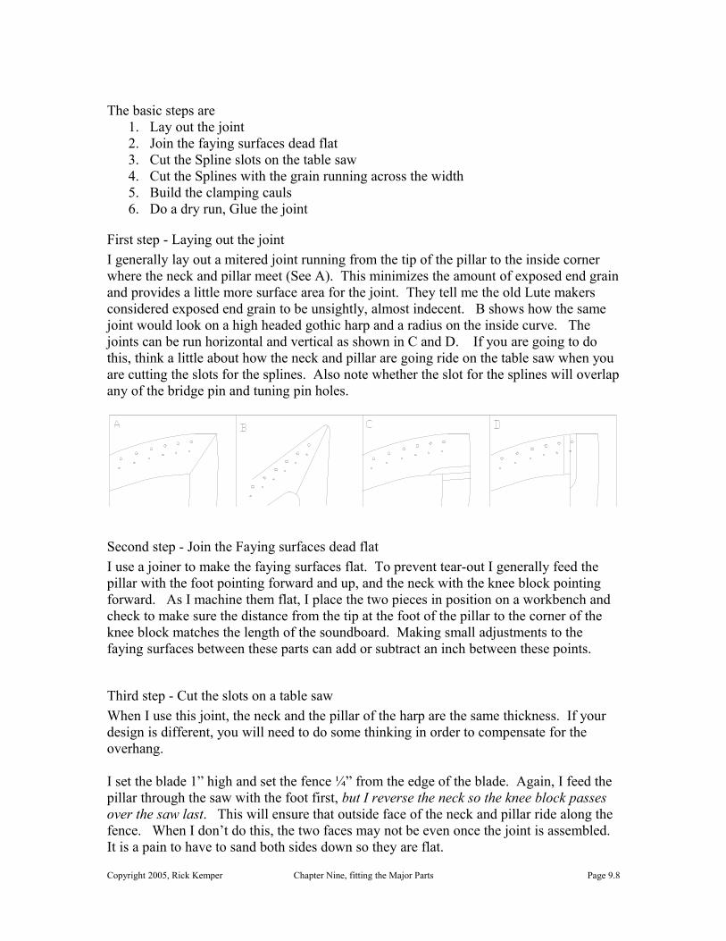
I generally lay out a mitered joint running from the tip of the pillar to the inside corner where the neck and pillar meet (See A). This minimizes the amount of exposed end grain and provides a little more surface area for the joint. They tell me the old Lute makers considered exposed end grain to be unsightly, almost indecent. B shows how the same joint would look on a high headed gothic harp and a radius on the inside curve. The joints can be run horizontal and vertical as shown in C and D. If you are going to do this, think a little about how the neck and pillar are going ride on the table saw when you are cutting the slots for the splines. Also note whether the slot for the splines will overlap any of the bridge pin and tuning pin holes.
Second step - Join the Faying surfaces dead flat
I use a joiner to make the faying surfaces flat. To prevent tear-out I generally feed the pillar with the foot pointing forward and up, and the neck with the knee block pointing forward. As I machine them flat, I place the two pieces in position on a workbench and check to make sure the distance from the tip at the foot of the pillar to the corner of the knee block matches the length of the soundboard. Making small adjustments to the faying surfaces between these parts can add or subtract an inch between these points.
Third step - Cut the slots on a table saw
When I use this joint, the neck and the pillar of the harp are the same thickness. If your design is different, you will need to do some thinking in order to compensate for the overhang.
I set the blade 1” high and set the fence ¼” from the edge of the blade. Again, I feed the pillar through the saw with the foot first, but I reverse the neck so the knee block passes over the saw last. This will ensure that outside face of the neck and pillar ride along the fence. When I don’t do this, the two faces may not be even once the joint is assembled. It is a pain to have to sand both sides down so they are flat.
Copyright 2005, Rick Kemper Chapter Nine, fitting the Major Parts Page 9.8

Once the first set of slots is cut, I move the fence to cut the second set of slots. I set the fence by turning off the saw and rotating the neck around so the saw blade is in the slot. Then I push the fence lightly against the neck and lock it into place. The splines both end up the same ¼” in from the face, which makes for a clean, symmetrical look.
Fourth Step - Cut the Splines It is important to cut the splines with the grain running across the width of the spline. It is tempting to rip the splines lengthwise, but the splines need to resist shear along the line of the joint and carry tension between the neck and the pillar. The splines need to be strong, so I usually make them from hard maple, Bubinga or Cherry.
The splines need to be 2” wide, so I cross cut a 2” block from the end of a board. Before I cut the stock I sight across the face of the board. Any cupping in the board is going result in a wandering cut or a spline that is too thin in the middle. I use a big belt sander make faces of the block flat.
At this point, the splines could be cut with a table saw, but it is a problematic cut at best. The blade has to cut up through the end grain, and even a new sharp blade will burn and scorch more than it really cuts. There is also a tendency for the spline to drop into the slot around the blade. If you insist on going with the table saw approach, use a zero clearance table saw insert, a finger board and push stick.
It is quicker and more precise to cut the splines of the block with a bandssaw, then sand them flat on a thickness sander. I make the bandsaw cut a millimeter or two thick, returning the block to a jointer or sander to keep one side of the spline flat. After I have cut the block into splines, I feed them through the thickness sander till the fit neatly into a test block that I have cut on the table saw. Ideally, the splines should slide into the saw kerf with little play.
Fifth Step - Build the clamping caulsThis is not an easy joint to clamp with conventional clamps. I use a trick I picked up from canoe builder we have on the Eastern shore. Marc Pettingill uses a jig like this to clamp the shear strakes bow and transom of his delightful tortured plywood canoes.
A clamping jig for the spline joint. The arrows show where the clamps should be exerting pressure.
If the clamp pressure is perpendicular to the joint line, the parts won’t slide around. The jigs are built from two strips of 3/8” AC plywood that are 12-18” long and as wide as the neck and pillar are thick. 3/8” ply is flexible enough to follow the curve on most necks and pillars. Luan isn’t strong enough. The triangular
Copyright 2005, Rick Kemper Chapter Nine, fitting the Major Parts Page 9.9

blocks are cut from the scraps left over from the neck and pillar. The triangles are glued and screwed onto the plywood strips. The angle and size of the triangular pieces are going to vary with the geometry of the joint.
After several unsuccessful attempts to use clamps to hold the cauls onto the neck and pillar, I resorted to a #8 x 1¼” screw. The holes they leave are fairly inconspicuous and easily filled.
Sixth Step - Do a dry run, then glue the jointI fit the parts together clamp them with moderate pressure. I use large C-clamps or bar clamps. I trim the corners of the splines to match the angle of the neck and pillar.
If my splines fit nicely and the cauls generate good clamping pressure, I glue with yellow glue or Weldwood plastic resin. If not, I resort to epoxy which can fill the gaps and does not demand as much pressure.
Fitting the Neck/Pillar to the Sound boxThe neck is held into place on the sound box with two 3/8 inch dowels. If the joint is perpendicular to the strings, it is in compression and the dowels simply keep the parts aligned. If it becomes necessary to take the harp apart for repairs down the road, it is a royal pain to pry this joint apart, so the joint is dry, no glue. The neck may not sit flat on the top of the sound box on the first fitting.
In a perfect world you would actually want a 1/8” gap on the side towards the strings (see detail). As the string tension is brought, up and the neck bends, this gap will close right
up. You can achieve this gap by trimming the bottom of the neck or top of the sound box.
Align the front edge of the knee block with the top edge of the sound box. An 1/8” gap on the side closest to the strings will close up as the string is brought under tension. It is best to leave the knee area larger than the pattern till fitting it to the sound box, and trim it when you do the final shaping of the knee.
Holding the shell into place - A simple block is cut from a 2x6 so it fits the back of the shell. The block is clamped to the workbench to steady the shell while the neck and pillar are fitted. It helps to attach the feet to the sound box to give it better stability too.
The fit is usually pretty close, and I fine tune it by noting which side needs to be trimmed and using a disk sander with a table to refine the angle. Before I discovered this I used a rounter to machine this surface flat and at the angle I
wanted.
Copyright 2005, Rick Kemper Chapter Nine, fitting the Major Parts Page 9.10

If you don’t have a disk sander, use the router. Clamp the neck upside down in a bench vise between two boards which extend above the neck. Use a straight bit to machine the surface flat. I check the clearance between the router and the front and back edges of the knee block and re-adjust the angle of the neck in the vice so the bit just barely clears the low side and will remove about 1/8” from the side that needs trimming.
<pic of router in tray, neck clamped into place>
The rectangular boards on either side of the neck are ripped to the same width and ride on the guide bars of the vice, providing two parallel edges for the router to ride on.
After I am satisfied with the fit between the pillar and sound box, I drill the holes into neck, trying to miss the dowels reinforcing the knee block. I drill corresponding holes into the top of the soundbox using centerpoints to locate the holes. For a five octave (36
string harp) I usually use two 1½ x 3/8 diameter dowel pins to hold the neck together. If the neck joint is not perpendicular to the strings you will need to use much larger dowels, or steel rod to keep the dowels from shearing.
Left - I use a jig block to ensure the holes are drilled perpendicular to the surface of the neck.
Right - I use dowel transfer points on the top of the sound box to prick two marks into the underside of the neck
After this joint is completed, I push the neck onto the dowels and scribe the foot of the pillar so I can trim it to rest flat on the string rib.
The foot of the pillar will naturally want to pull to the left side of the string band. As you center it, you will make the neck lean away from the strings. I used worry about this and carefully worked out joints that had a 1-2 degree angle between the neck and pillar. To my dismay, I found the string tension usually made the neck start leaning too far towards the strings – the strain is enough over time to make the pillar bend. I make the pillar joints straight now, and after the harp has been up to tension for a few months the necks are just about vertical.
Copyright 2005, Rick Kemper Chapter Nine, fitting the Major Parts Page 9.11

Attaching the foot of the PillarThis will vary with the design. For Medium and high tension harps, I usually bolt the foot of the pillar through the string band, driving the bolt from within the sound box. With a 3/8 x 2½ inch lag screw.
Cutaway view of the bolt securing the foot of the pillar. It is much easier to insert the bolt and tighten it with a ratchet wrench if the bolt is higher, up off the floor of the base, entering near the “heel” of the pillar instead of the toe.
In some designs, there is no room to start the bolt, so I cut a 3½” diameter access hole into the base of the sound box to facilitate this.
I drill a ¼” hole into the foot of the pillar. To ensure the bolt will not split the foot of the pillar when it is bolted into place, I clamp the foot tightly and drive the bolt in and out – effectively cutting threads into the hole.
I place a center point into the hole and put the neck and pillar assembly into place. I center the foot over the string rib and press the center point down. I remove the neck/pillar assembly and drill a 3/8 hole through the divot left by the center point, through the soundboard and string ribs.
If the harp is a round or stave back harp, I round the knee block area of the harp at this point. I use a band saw to hog off the corners of the knee block and neck. I attach the neck/pillar to the sound box with the dowels and use a strap clamp over the top of the neck and under the sound box to hold the neck firmly in place while I finish rounding it off. I use a 4” power grinder with a carbide whisker grinding disk to refine the shape. The final rounding is done with a hand rasp, orbital sander and scraper. It can take a half hour or so but the sculpted result is always well worth the effort.
Copyright 2005, Rick Kemper Chapter Nine, fitting the Major Parts Page 9.12
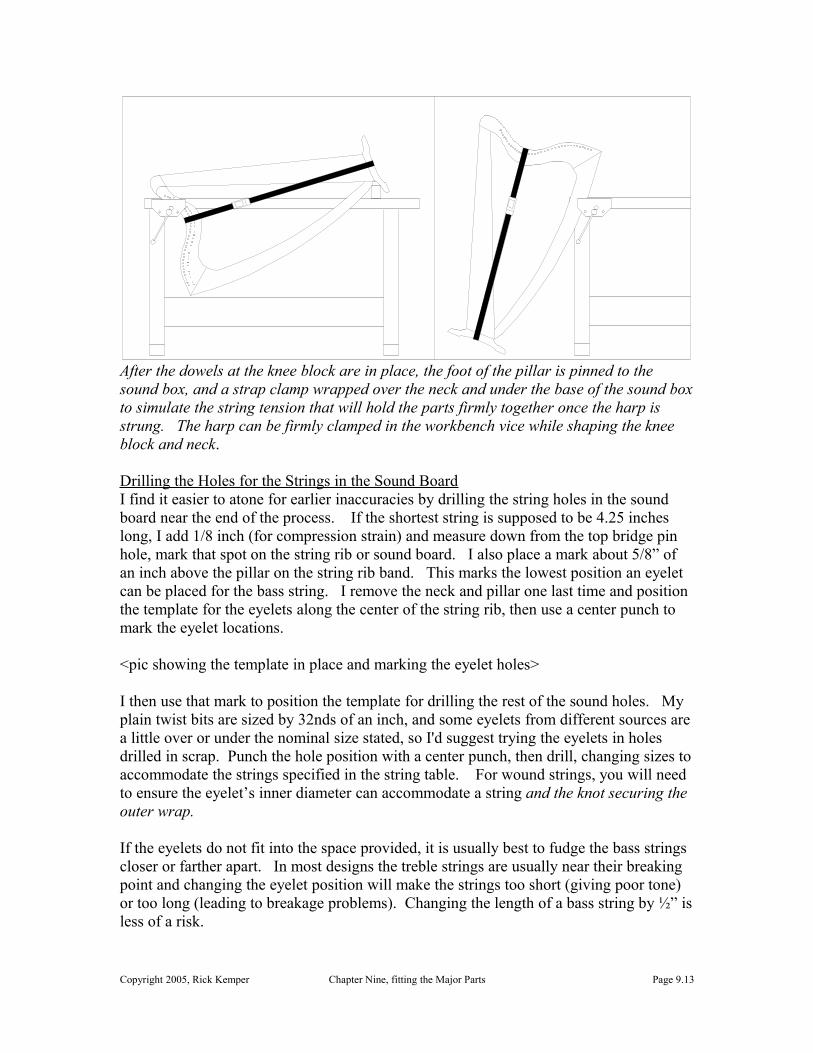
After the dowels at the knee block are in place, the foot of the pillar is pinned to the sound box, and a strap clamp wrapped over the neck and under the base of the sound box to simulate the string tension that will hold the parts firmly together once the harp is strung. The harp can be firmly clamped in the workbench vice while shaping the knee block and neck.
Drilling the Holes for the Strings in the Sound BoardI find it easier to atone for earlier inaccuracies by drilling the string holes in the sound board near the end of the process. If the shortest string is supposed to be 4.25 inches long, I add 1/8 inch (for compression strain) and measure down from the top bridge pin hole, mark that spot on the string rib or sound board. I also place a mark about 5/8” of an inch above the pillar on the string rib band. This marks the lowest position an eyelet can be placed for the bass string. I remove the neck and pillar one last time and position the template for the eyelets along the center of the string rib, then use a center punch to mark the eyelet locations.
<pic showing the template in place and marking the eyelet holes>
I then use that mark to position the template for drilling the rest of the sound holes. My plain twist bits are sized by 32nds of an inch, and some eyelets from different sources are a little over or under the nominal size stated, so I'd suggest trying the eyelets in holes drilled in scrap. Punch the hole position with a center punch, then drill, changing sizes to accommodate the strings specified in the string table. For wound strings, you will need to ensure the eyelet’s inner diameter can accommodate a string and the knot securing the outer wrap.
If the eyelets do not fit into the space provided, it is usually best to fudge the bass strings closer or farther apart. In most designs the treble strings are usually near their breaking point and changing the eyelet position will make the strings too short (giving poor tone) or too long (leading to breakage problems). Changing the length of a bass string by ½” is less of a risk.
Copyright 2005, Rick Kemper Chapter Nine, fitting the Major Parts Page 9.13

This is a major milestone in the building process. The harp is now ready for final scraping and sanding and a coat of finish.
Copyright 2005, Rick Kemper Chapter Nine, fitting the Major Parts Page 9.14