Embed Size (px)
Citation preview

Chapter 26
Capacitance and Dielectrics

Circuits and Circuit Elements
Electric circuits are the basis for the vast majority of the devices used in society.
Circuit elements can be connected with wires to form electric circuits.
Capacitors are one circuit element.
Introduction Prof Dr Ahmet ATAÇ

Capacitors
Capacitors are devices that store electric charge.
Examples of where capacitors are used include:
radio receivers
filters in power supplies
to eliminate sparking in automobile ignition systems
energy-storing devices in electronic flashes
Introduction Prof Dr Ahmet ATAÇ
Capacitors
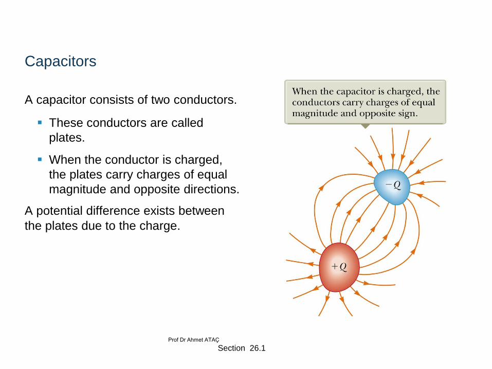
A capacitor consists of two conductors.
These conductors are called
plates.
When the conductor is charged,
the plates carry charges of equal
magnitude and opposite directions.
A potential difference exists between
the plates due to the charge.
Section 26.1 Prof Dr Ahmet ATAÇ

Definition of Capacitance
The capacitance, C, of a capacitor is defined as the ratio of the magnitude of the
charge on either conductor to the potential difference between the conductors.
The SI unit of capacitance is the farad (F).
The farad is a large unit, typically you will see microfarads (mF) and picofarads
(pF).
Capacitance will always be a positive quantity
The capacitance of a given capacitor is constant.
The capacitance is a measure of the capacitor’s ability to store charge .
The capacitance of a capacitor is the amount of charge the capacitor can store per unit of potential difference.
QC
V
Section 26.1 Prof Dr Ahmet ATAÇ
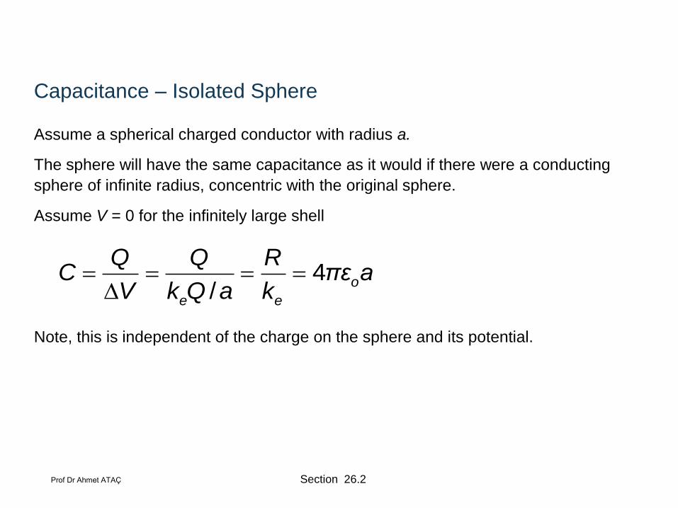
Capacitance – Isolated Sphere
Assume a spherical charged conductor with radius a.
The sphere will have the same capacitance as it would if there were a conducting
sphere of infinite radius, concentric with the original sphere.
Assume V = 0 for the infinitely large shell
Note, this is independent of the charge on the sphere and its potential.
4/
o
e e
Q Q RC πε a
V k Q a k
Section 26.2 Prof Dr Ahmet ATAÇ

Parallel Plate Capacitor
Each plate is connected to a terminal of
the battery.
The battery is a source of potential
difference.
If the capacitor is initially uncharged,
the battery establishes an electric field
in the connecting wires.
Section 26.1 Prof Dr Ahmet ATAÇ
Parallel Plate Capacitor, cont
This field applies a force on electrons in the wire just outside of the plates.
The force causes the electrons to move onto the negative plate.
This continues until equilibrium is achieved.
The plate, the wire and the terminal are all at the same potential.
At this point, there is no field present in the wire and the movement of the
electrons ceases.
The plate is now negatively charged.
A similar process occurs at the other plate, electrons moving away from the plate and leaving it positively charged.
In its final configuration, the potential difference across the capacitor plates is the same as that between the terminals of the battery.
Section 26.1 Prof Dr Ahmet ATAÇ

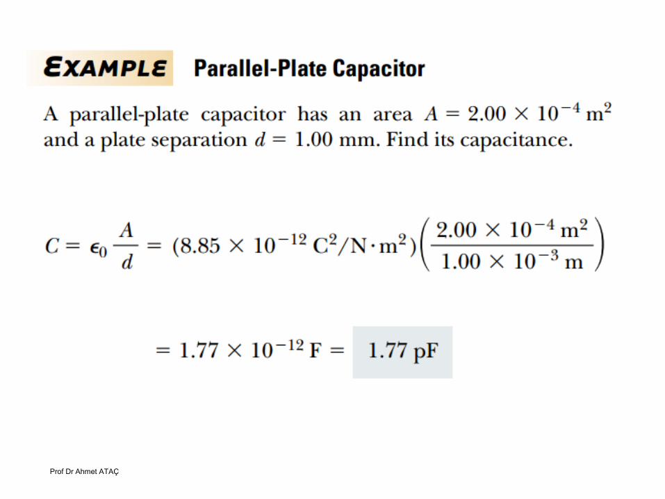
Capacitance – Parallel Plates
The charge density on the plates is σ = Q/A.
A is the area of each plate, the area of each plate is equal
Q is the charge on each plate, equal with opposite signs
The electric field is uniform between the plates and zero elsewhere.
The capacitance is proportional to the area of its plates and inversely
proportional to the distance between the plates.
/o
o
ε AQ Q QC
V Ed Qd ε A d
Section 26.2 Prof Dr Ahmet ATAÇ
Prof Dr Ahmet ATAÇ
Prof Dr Ahmet ATAÇ
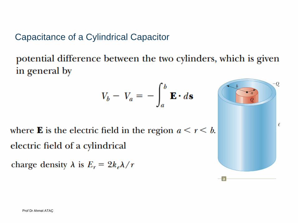
Capacitance of a Cylindrical Capacitor

Prof Dr Ahmet ATAÇ
Capacitance of a Cylindrical Capacitor
V = -2keln (b/a)
= Q/l
The capacitance is
2 ln /e
QC
V k b a
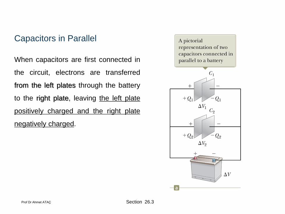
Capacitors in Parallel
When capacitors are first connected in
the circuit, electrons are transferred
from the left plates through the battery
to the right plate, leaving the left plate
positively charged and the right plate
negatively charged.
Section 26.3 Prof Dr Ahmet ATAÇ
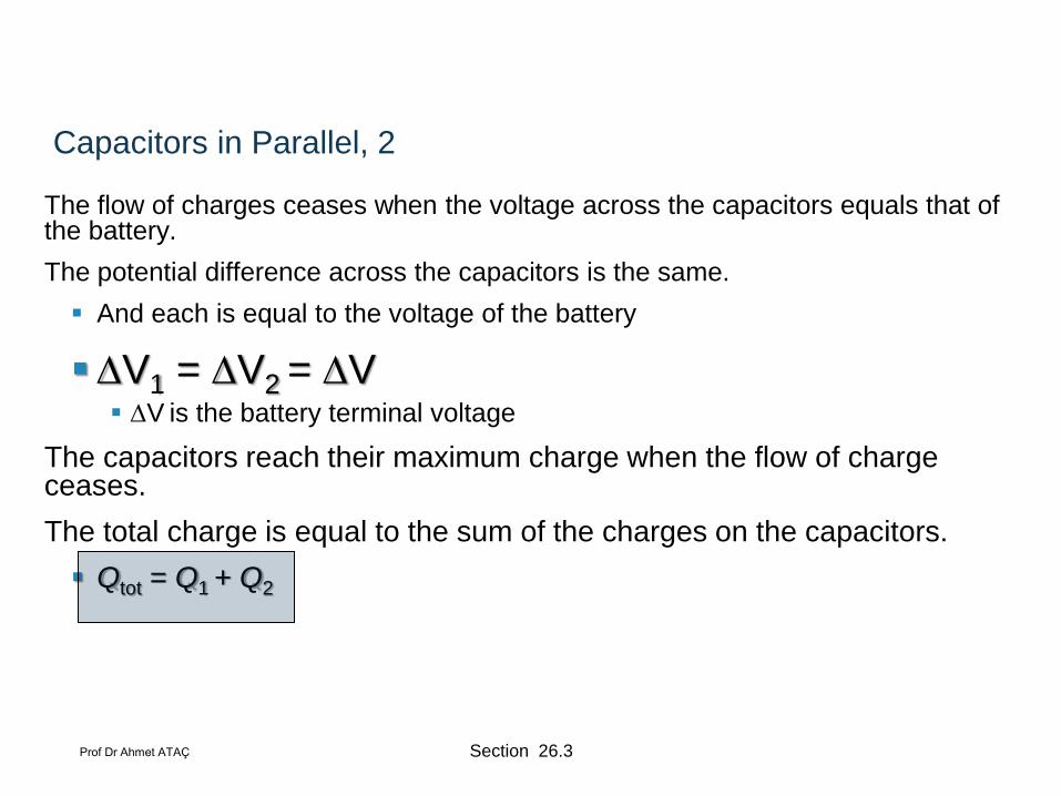
Capacitors in Parallel, 2
The flow of charges ceases when the voltage across the capacitors equals that of the battery.
The potential difference across the capacitors is the same.
And each is equal to the voltage of the battery
V1 = V2 = V V is the battery terminal voltage
The capacitors reach their maximum charge when the flow of charge ceases.
The total charge is equal to the sum of the charges on the capacitors.
Qtot = Q1 + Q2
Section 26.3 Prof Dr Ahmet ATAÇ

Capacitors in Parallel, 3
The capacitors can be replaced with
one capacitor with a capacitance of Ceq.
The equivalent capacitor must
have exactly the same external
effect on the circuit as the original
capacitors.
Section 26.3 Prof Dr Ahmet ATAÇ

Capacitors in Parallel, final
Ceq = C1 + C2 + C3 + …
The equivalent capacitance of a parallel combination of capacitors is greater than
any of the individual capacitors.
Essentially, the areas are combined
Section 26.3 Prof Dr Ahmet ATAÇ

Capacitors in Series
When a battery is connected to the
circuit, electrons are transferred from
the left plate of C1 to the right plate of
C2 through the battery.
As this negative charge accumulates
on the right plate of C2, an equivalent
amount of negative charge is
removed from the left plate of C2,
leaving it with an excess positive
charge.
All of the right plates gain charges of
–Q and all the left plates have
charges of +Q.
Section 26.3 Prof Dr Ahmet ATAÇ

Capacitors in Series, cont.
An equivalent capacitor can be found
that performs the same function as the
series combination.
The charges are all the same.
Q1 = Q2 = Q
Section 26.3 Prof Dr Ahmet ATAÇ

Capacitors in Series, final
The potential differences add up to the battery voltage.
ΔVtot = V1 + V2 + …
The equivalent capacitance is
The equivalent capacitance of a series combination is always less than any individual capacitor in the combination.
1 2 3
1 1 1 1
eqC C C C
Section 26.3 Prof Dr Ahmet ATAÇ

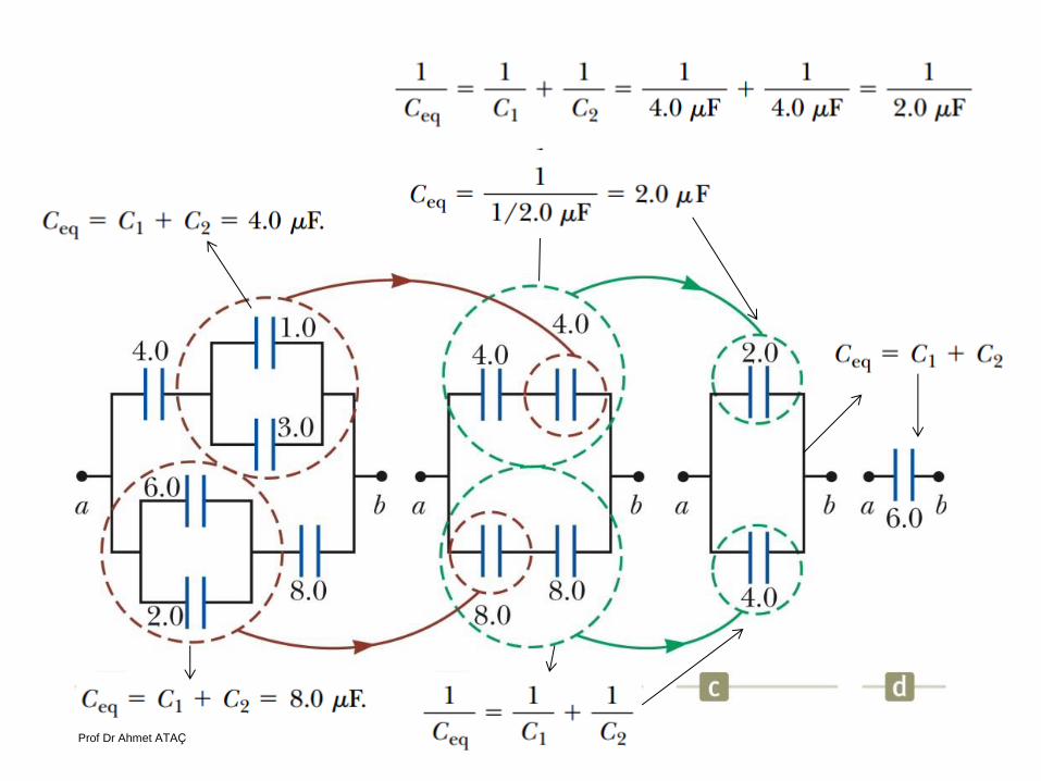
Equivalent Capacitance, Example
Find the equivalent capacitance between a and b. All capciatnce are in microfarads.
Section 26.3 Prof Dr Ahmet ATAÇ
Prof Dr Ahmet ATAÇ

Energy in a Capacitor – Overview
Consider the circuit to be a system.
Before the switch is closed, the energy is stored as chemical energy in the battery.
When the switch is closed, the energy is transformed from chemical potential energy to electric potential energy.
The electric potential energy is related
to the separation of the positive and
negative charges on the plates.
A capacitor can be described as a
device that stores energy as well as
charge.
Section 26.4 Prof Dr Ahmet ATAÇ
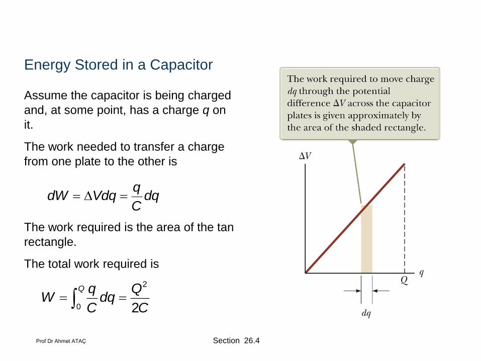
Energy Stored in a Capacitor
Assume the capacitor is being charged
and, at some point, has a charge q on
it.
The work needed to transfer a charge
from one plate to the other is
The work required is the area of the tan
rectangle.
The total work required is
qdW Vdq dq
C
2
0 2
Q q QW dq
C C
Section 26.4 Prof Dr Ahmet ATAÇ

Energy, cont
The work done in charging the capacitor appears as electric potential energy U:
This applies to a capacitor of any geometry.
The energy stored increases as the charge increases and as the potential difference increases.
In practice, there is a maximum voltage before discharge occurs between the plates.
221 1
( )2 2 2
QU Q V C V
C
Section 26.4 Prof Dr Ahmet ATAÇ
Energy, final
The energy can be considered to be stored in the electric field .
For a parallel-plate capacitor, the energy can be expressed in terms of the field as
U = ½ (εoAd)E2.
It can also be expressed in terms of the energy density (energy per unit volume)
uE = ½ eoE2.
Section 26.4 Prof Dr Ahmet ATAÇ
Some Uses of Capacitors
Defibrillators
When cardiac fibrillation occurs, the heart produces a rapid, irregular pattern of beats
A fast discharge of electrical energy through the heart can return the organ to its normal beat pattern.
In general, capacitors act as energy reservoirs that can be slowly charged and then discharged quickly to provide large amounts of energy in a short pulse.
Section 26.4 Prof Dr Ahmet ATAÇ
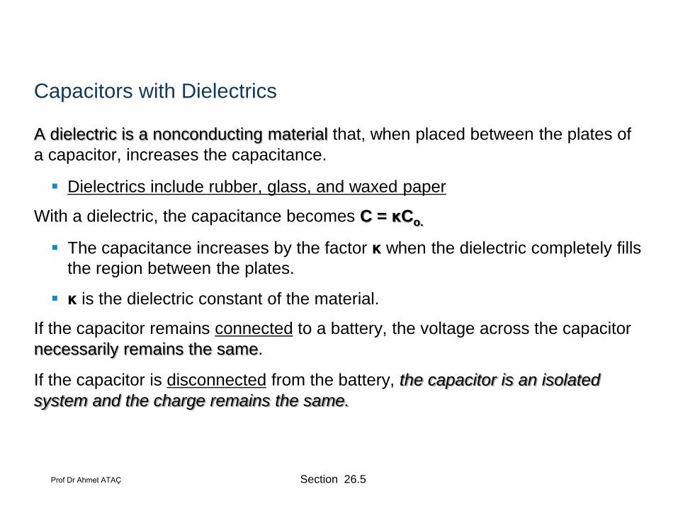
Capacitors with Dielectrics
A dielectric is a nonconducting material that, when placed between the plates of
a capacitor, increases the capacitance.
Dielectrics include rubber, glass, and waxed paper
With a dielectric, the capacitance becomes C = κCo.
The capacitance increases by the factor κ when the dielectric completely fills
the region between the plates.
κ is the dielectric constant of the material.
If the capacitor remains connected to a battery, the voltage across the capacitor
necessarily remains the same.
If the capacitor is disconnected from the battery, the capacitor is an isolated
system and the charge remains the same.
Section 26.5 Prof Dr Ahmet ATAÇ

Dielectrics, cont
For a parallel-plate capacitor, C = κ (εoA) / d
In theory, d could be made very small to create a very large capacitance.
In practice, there is a limit to d.
d is limited by the electric discharge that could occur though the dielectric medium separating the plates.
For a given d, the maximum voltage that can be applied to a capacitor without causing a discharge depends on the dielectric strength of the material.
Section 26.5 Prof Dr Ahmet ATAÇ
Dielectrics, final
Dielectrics provide the following advantages:
Increase in capacitance
Increase the maximum operating voltage
Possible mechanical support between the plates
This allows the plates to be close together without touching.
This decreases d and increases C.
Section 26.5 Prof Dr Ahmet ATAÇ
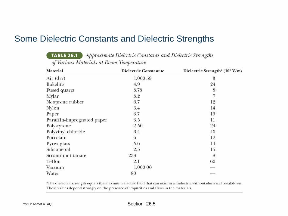
Some Dielectric Constants and Dielectric Strengths
Section 26.5 Prof Dr Ahmet ATAÇ