Embed Size (px)
Citation preview
Chapter 9 Welding and the Design
of Permanent Joints
9/28/2013 10:22 PM
Dr. Mohammad Suliman Abuhaiba, PE 1

Chapter Outline
9/28/2013 10:22 PM
Dr. Mohammad Suliman Abuhaiba, PE
2
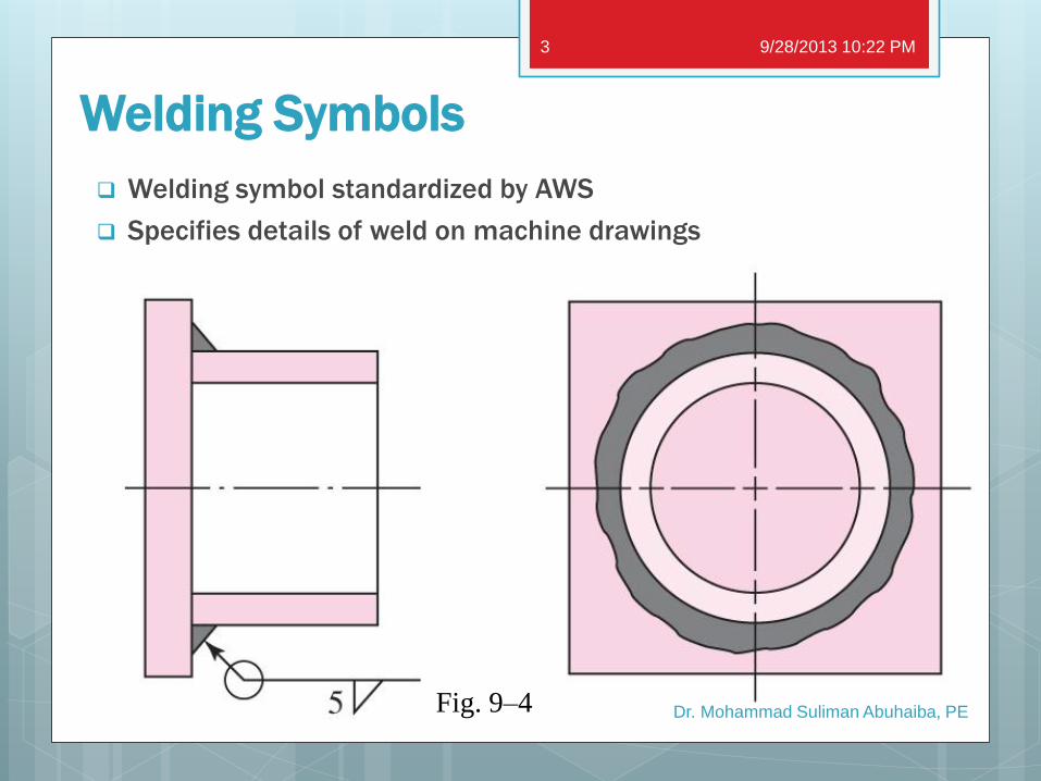
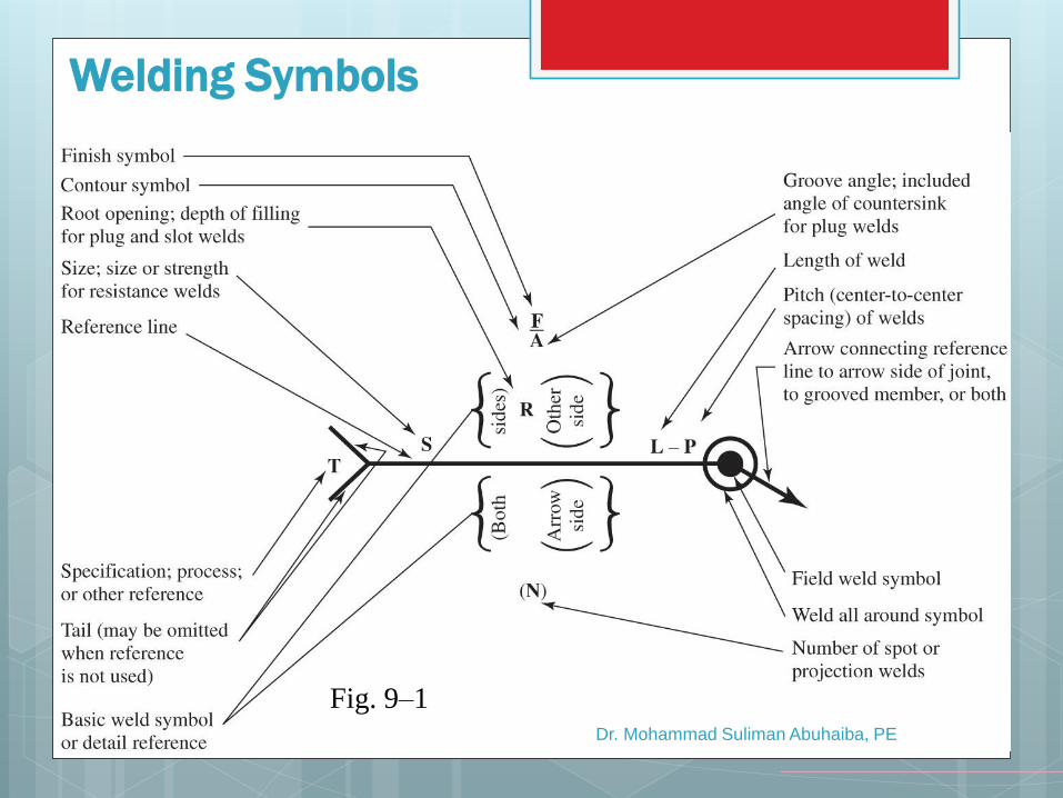
Welding Symbols
Welding symbol standardized by AWS
Specifies details of weld on machine drawings
Fig. 9–4
9/28/2013 10:22 PM
Dr. Mohammad Suliman Abuhaiba, PE
3
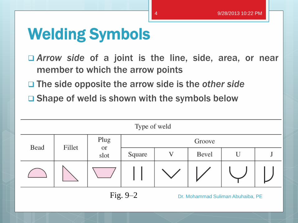
Welding Symbols
Arrow side of a joint is the line, side, area, or near
member to which the arrow points
The side opposite the arrow side is the other side
Shape of weld is shown with the symbols below
Fig. 9–2
9/28/2013 10:22 PM
Dr. Mohammad Suliman Abuhaiba, PE
4
Dr. Mohammad Suliman Abuhaiba, PE
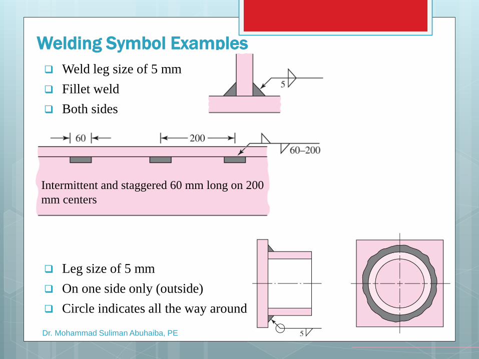
Welding Symbol Examples
Weld leg size of 5 mm
Fillet weld
Both sides
Leg size of 5 mm
On one side only (outside)
Circle indicates all the way around
Intermittent and staggered 60 mm long on 200
mm centers
Dr. Mohammad Suliman Abuhaiba, PE
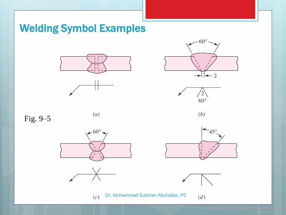
Welding Symbol Examples
Fig. 9–5
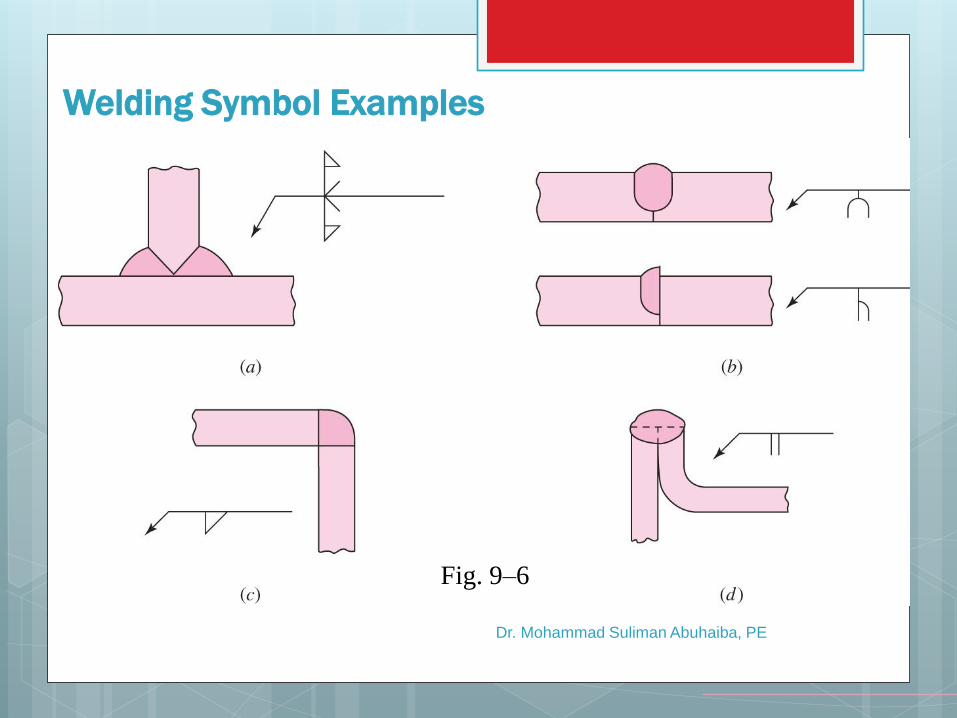
Dr. Mohammad Suliman Abuhaiba, PE
Welding Symbol Examples
Fig. 9–6
Dr. Mohammad Suliman Abuhaiba, PE
Welding Symbols
Fig. 9–1
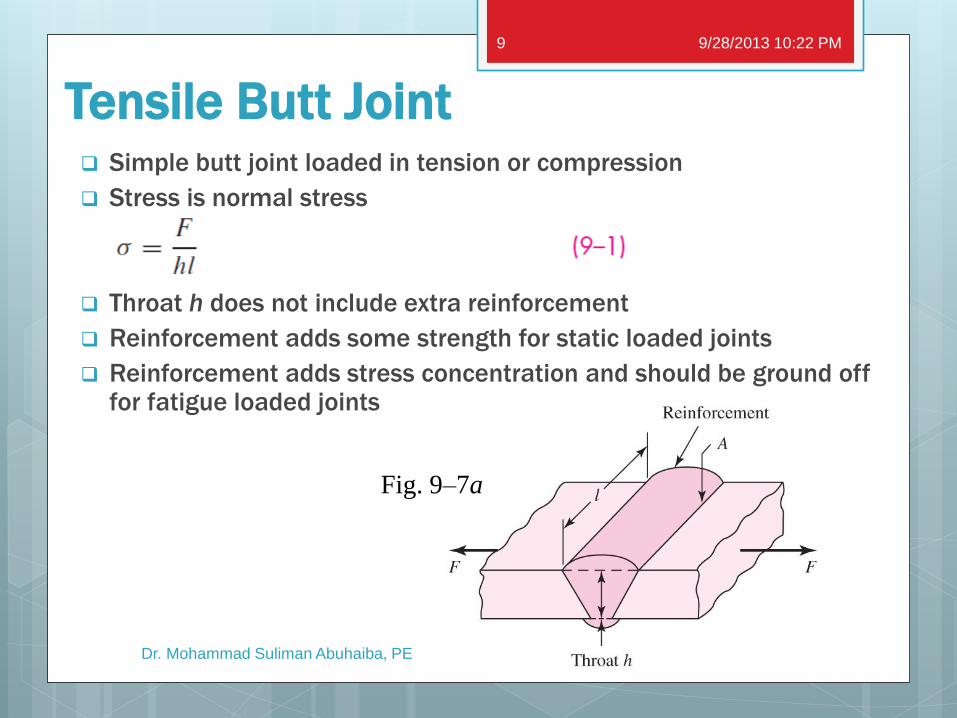
Tensile Butt Joint Simple butt joint loaded in tension or compression
Stress is normal stress
Throat h does not include extra reinforcement
Reinforcement adds some strength for static loaded joints
Reinforcement adds stress concentration and should be ground off for fatigue loaded joints
Fig. 9–7a
9/28/2013 10:22 PM
Dr. Mohammad Suliman Abuhaiba, PE
9
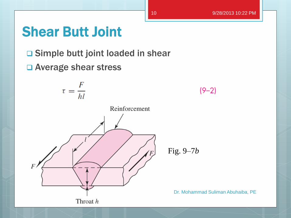
Shear Butt Joint
Simple butt joint loaded in shear
Average shear stress
Fig. 9–7b
9/28/2013 10:22 PM
Dr. Mohammad Suliman Abuhaiba, PE
10
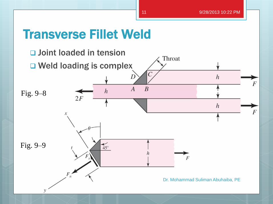
Transverse Fillet Weld
Joint loaded in tension
Weld loading is complex
Fig. 9–8
Fig. 9–9
9/28/2013 10:22 PM
Dr. Mohammad Suliman Abuhaiba, PE
11
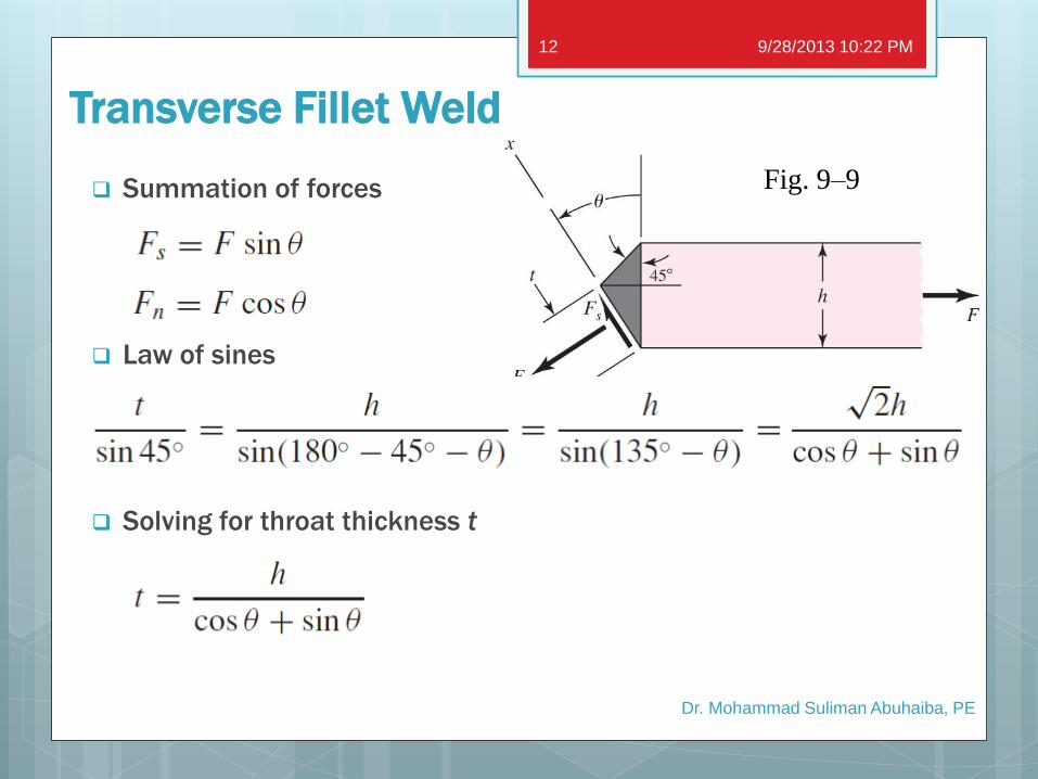
Transverse Fillet Weld
Summation of forces
Law of sines
Solving for throat thickness t
Fig. 9–9
9/28/2013 10:22 PM
Dr. Mohammad Suliman Abuhaiba, PE
12
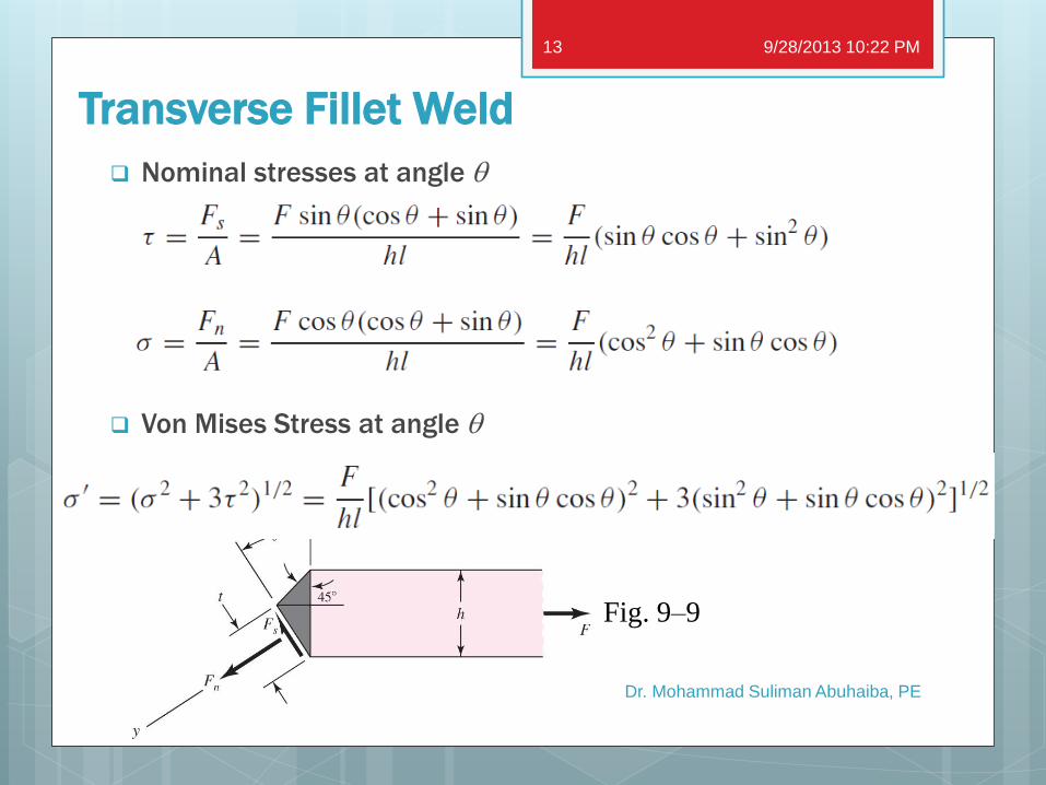
Transverse Fillet Weld
Nominal stresses at angle q
Von Mises Stress at angle q
Fig. 9–9
9/28/2013 10:22 PM
Dr. Mohammad Suliman Abuhaiba, PE
13
Transverse Fillet Weld
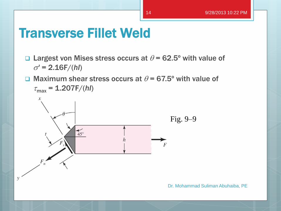
Largest von Mises stress occurs at q = 62.5º with value of
s' = 2.16F/(hl)
Maximum shear stress occurs at q = 67.5º with value of
tmax = 1.207F/(hl)
Fig. 9–9
9/28/2013 10:22 PM
Dr. Mohammad Suliman Abuhaiba, PE
14
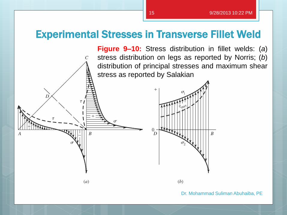
Experimental Stresses in Transverse Fillet Weld
9/28/2013 10:22 PM
Dr. Mohammad Suliman Abuhaiba, PE
15
Figure 9–10: Stress distribution in fillet welds: (a)
stress distribution on legs as reported by Norris; (b)
distribution of principal stresses and maximum shear
stress as reported by Salakian
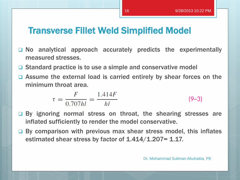
Transverse Fillet Weld Simplified Model
No analytical approach accurately predicts the experimentally
measured stresses.
Standard practice is to use a simple and conservative model
Assume the external load is carried entirely by shear forces on the
minimum throat area.
By ignoring normal stress on throat, the shearing stresses are
inflated sufficiently to render the model conservative.
By comparison with previous max shear stress model, this inflates
estimated shear stress by factor of 1.414/1.207= 1.17.
9/28/2013 10:22 PM
Dr. Mohammad Suliman Abuhaiba, PE
16
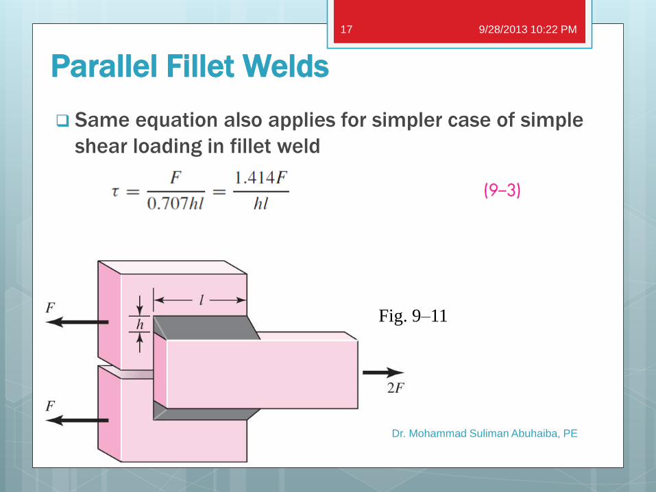
Parallel Fillet Welds
Same equation also applies for simpler case of simple
shear loading in fillet weld
Fig. 9–11
9/28/2013 10:22 PM
Dr. Mohammad Suliman Abuhaiba, PE
17
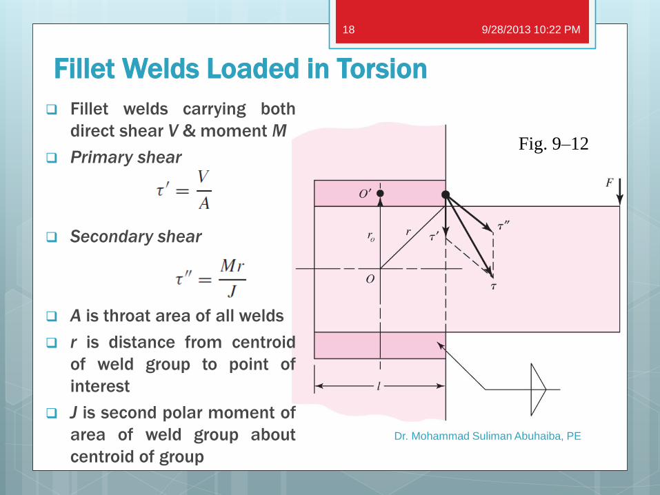
Fillet Welds Loaded in Torsion
Fillet welds carrying both
direct shear V & moment M
Primary shear
Secondary shear
A is throat area of all welds
r is distance from centroid
of weld group to point of
interest
J is second polar moment of
area of weld group about
centroid of group
Fig. 9–12
9/28/2013 10:22 PM
Dr. Mohammad Suliman Abuhaiba, PE
18
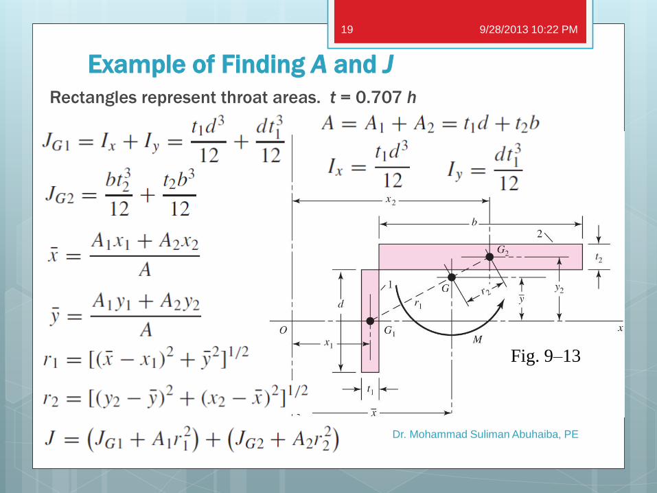
Example of Finding A and J
Rectangles represent throat areas. t = 0.707 h
Fig. 9–13
9/28/2013 10:22 PM
Dr. Mohammad Suliman Abuhaiba, PE
19
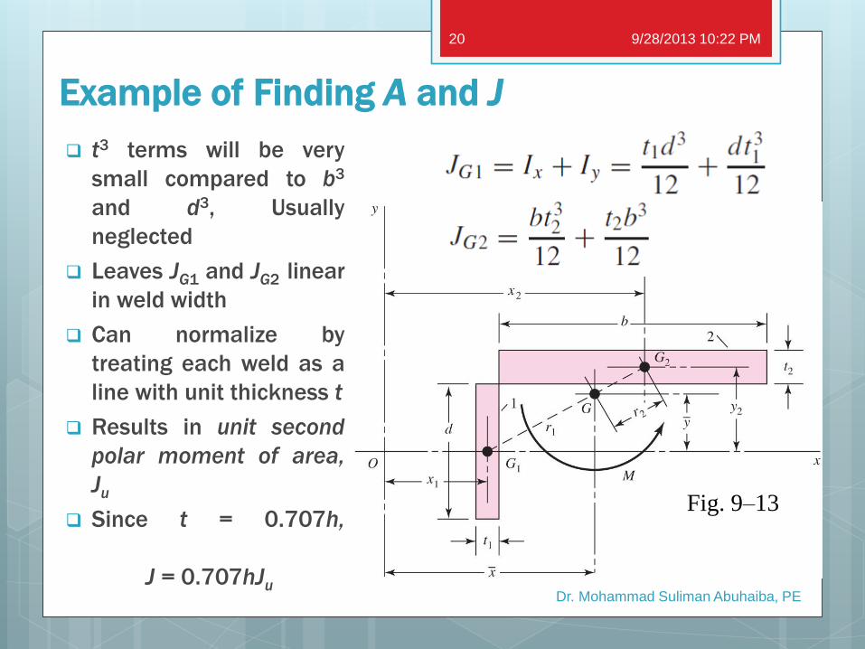
Example of Finding A and J
t3 terms will be very
small compared to b3
and d3, Usually
neglected
Leaves JG1 and JG2 linear
in weld width
Can normalize by
treating each weld as a
line with unit thickness t
Results in unit second
polar moment of area,
Ju
Since t = 0.707h,
J = 0.707hJu
Fig. 9–13
9/28/2013 10:22 PM
Dr. Mohammad Suliman Abuhaiba, PE
20
Dr. Mohammad Suliman Abuhaiba, PE
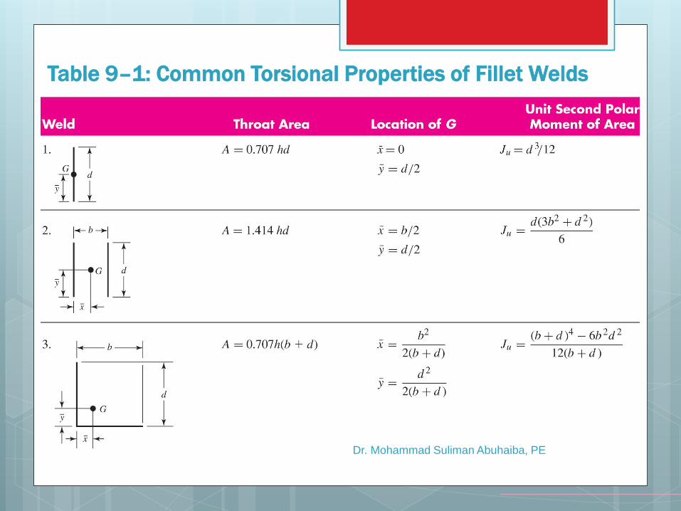
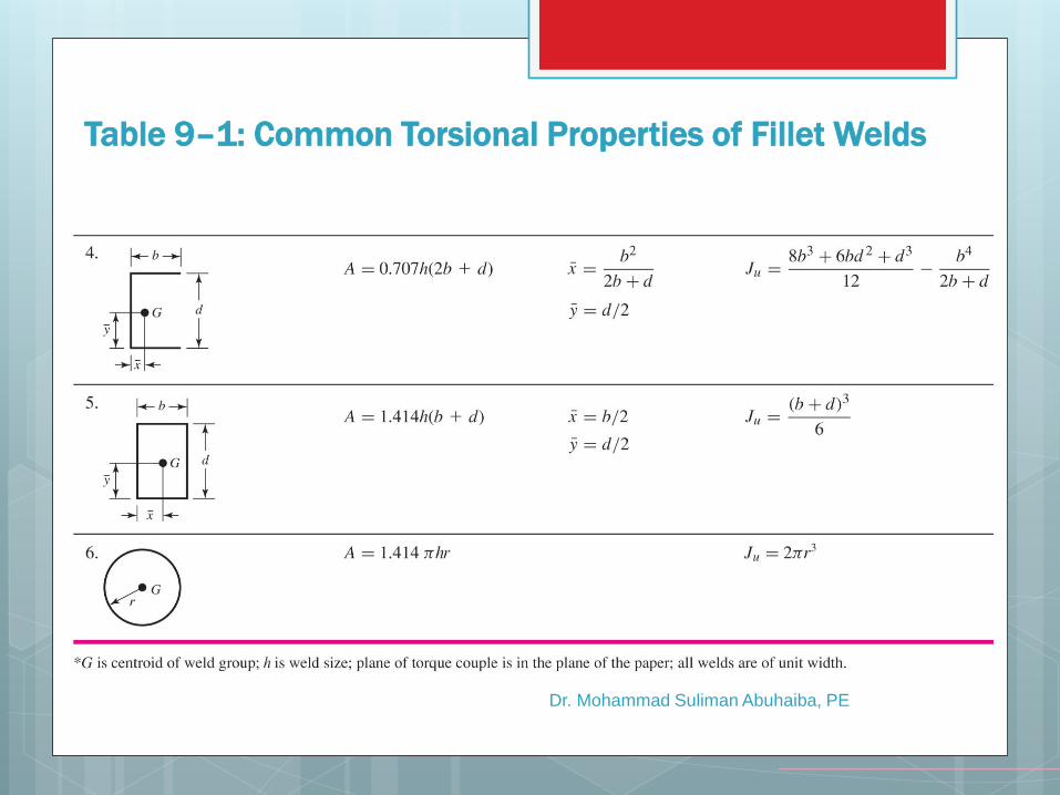
Table 9–1: Common Torsional Properties of Fillet Welds
Dr. Mohammad Suliman Abuhaiba, PE
Table 9–1: Common Torsional Properties of Fillet Welds
Dr. Mohammad Suliman Abuhaiba, PE
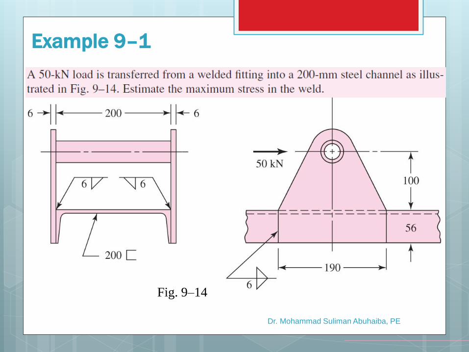
Example 9–1
Fig. 9–14
Dr. Mohammad Suliman Abuhaiba, PE
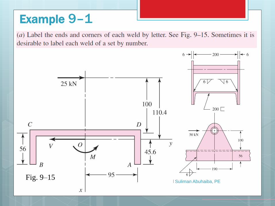
Example 9–1
Fig. 9–15
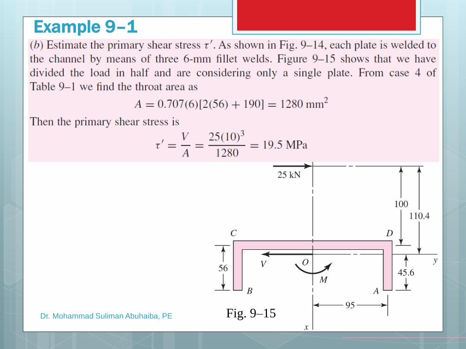
Example 9–1
Dr. Mohammad Suliman Abuhaiba, PE Fig. 9–15
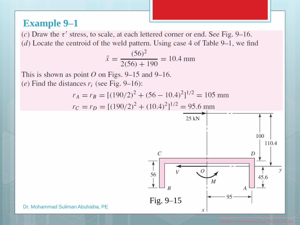
Dr. Mohammad Suliman Abuhaiba, PE
Example 9–1
Shigley’s Mechanical Engineering Design
Fig. 9–15
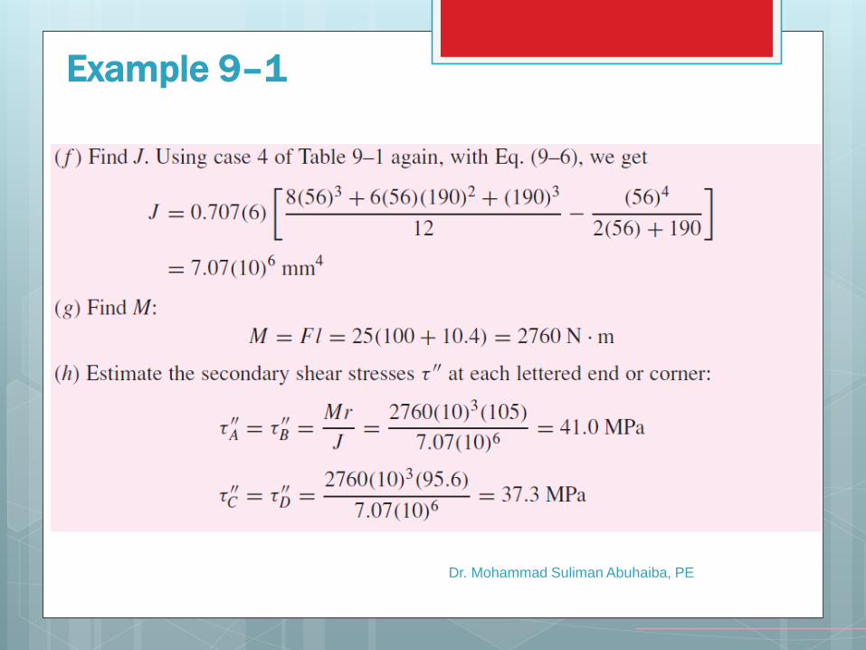
Dr. Mohammad Suliman Abuhaiba, PE
Example 9–1
Dr. Mohammad Suliman Abuhaiba, PE
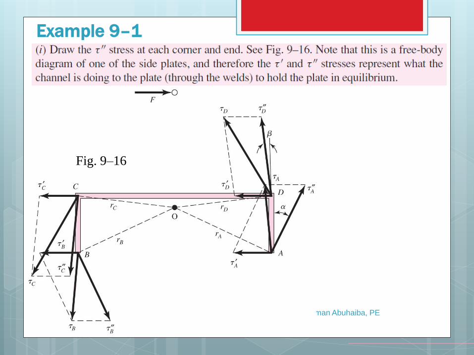
Example 9–1
Fig. 9–16
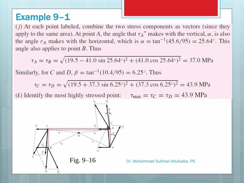
Dr. Mohammad Suliman Abuhaiba, PE
Example 9–1
Fig. 9–16
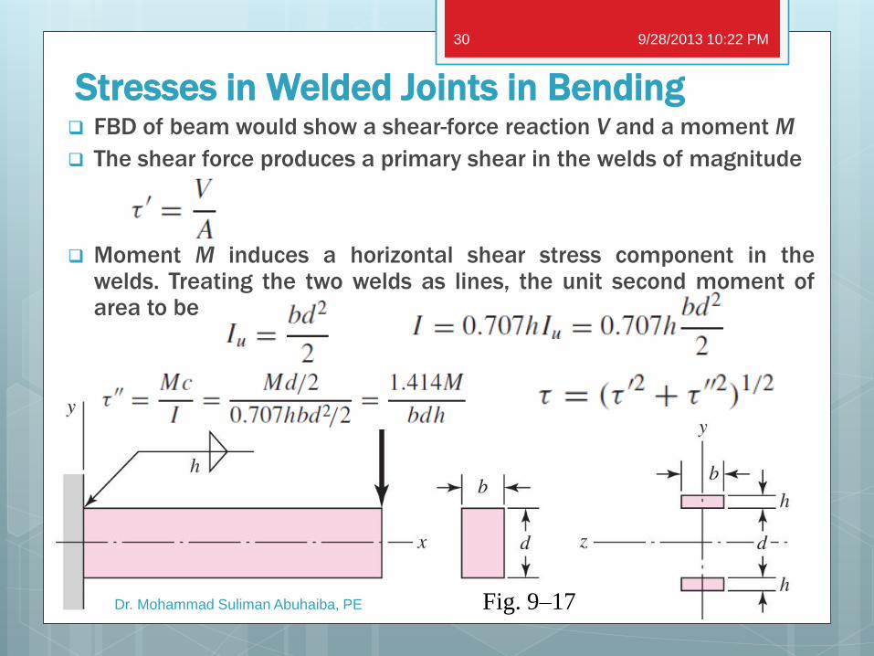
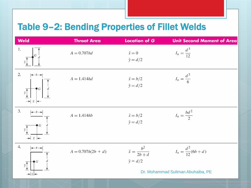
Stresses in Welded Joints in Bending FBD of beam would show a shear-force reaction V and a moment M
The shear force produces a primary shear in the welds of magnitude
Moment M induces a horizontal shear stress component in the welds. Treating the two welds as lines, the unit second moment of area to be
Fig. 9–17
9/28/2013 10:22 PM
Dr. Mohammad Suliman Abuhaiba, PE
30
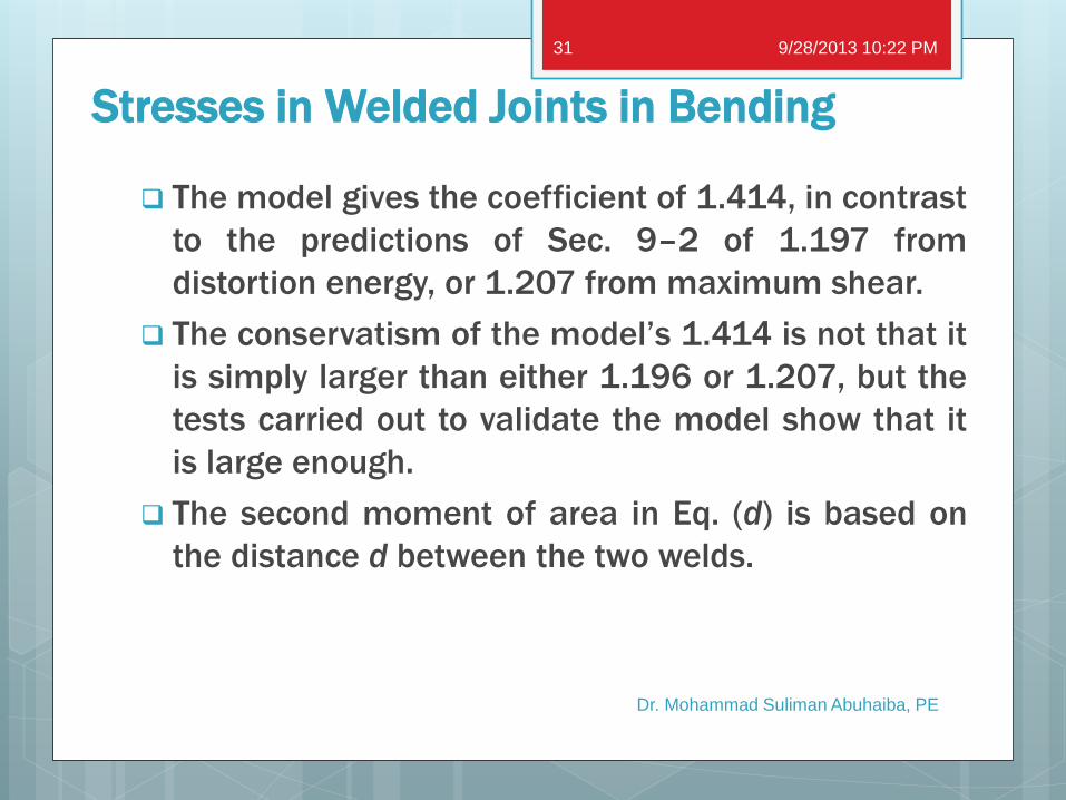
The model gives the coefficient of 1.414, in contrast
to the predictions of Sec. 9–2 of 1.197 from
distortion energy, or 1.207 from maximum shear.
The conservatism of the model’s 1.414 is not that it
is simply larger than either 1.196 or 1.207, but the
tests carried out to validate the model show that it
is large enough.
The second moment of area in Eq. (d) is based on
the distance d between the two welds.
9/28/2013 10:22 PM
Dr. Mohammad Suliman Abuhaiba, PE
31
Stresses in Welded Joints in Bending
Dr. Mohammad Suliman Abuhaiba, PE
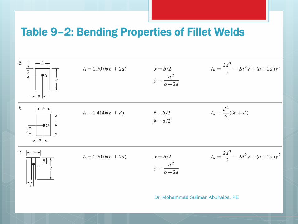
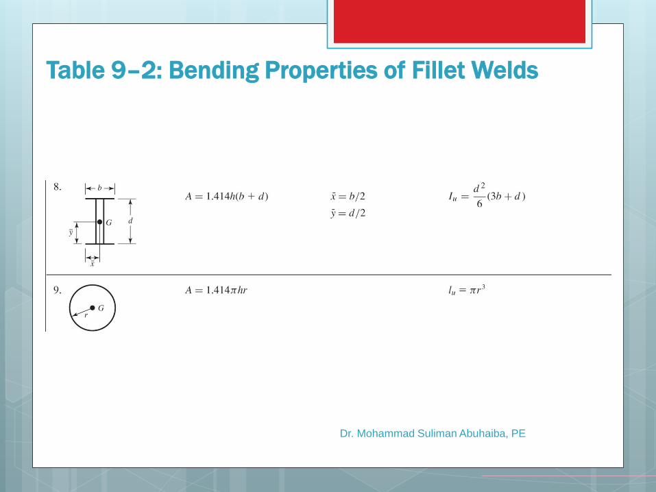
Table 9–2: Bending Properties of Fillet Welds
Dr. Mohammad Suliman Abuhaiba, PE
Table 9–2: Bending Properties of Fillet Welds
Dr. Mohammad Suliman Abuhaiba, PE
Table 9–2: Bending Properties of Fillet Welds
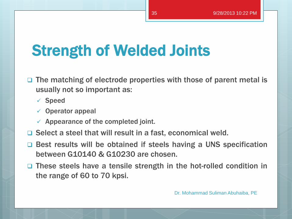
Strength of Welded Joints
The matching of electrode properties with those of parent metal is
usually not so important as:
Speed
Operator appeal
Appearance of the completed joint.
Select a steel that will result in a fast, economical weld.
Best results will be obtained if steels having a UNS specification
between G10140 & G10230 are chosen.
These steels have a tensile strength in the hot-rolled condition in
the range of 60 to 70 kpsi.
9/28/2013 10:22 PM
Dr. Mohammad Suliman Abuhaiba, PE
35
Dr. Mohammad Suliman Abuhaiba, PE
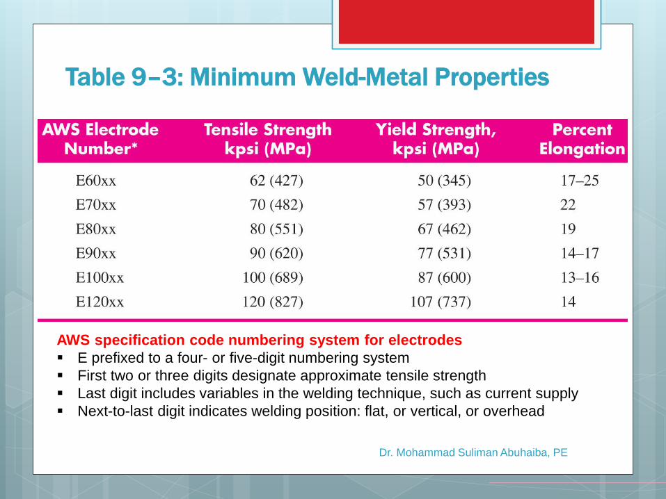
Table 9–3: Minimum Weld-Metal Properties
AWS specification code numbering system for electrodes
E prefixed to a four- or five-digit numbering system
First two or three digits designate approximate tensile strength
Last digit includes variables in the welding technique, such as current supply
Next-to-last digit indicates welding position: flat, or vertical, or overhead
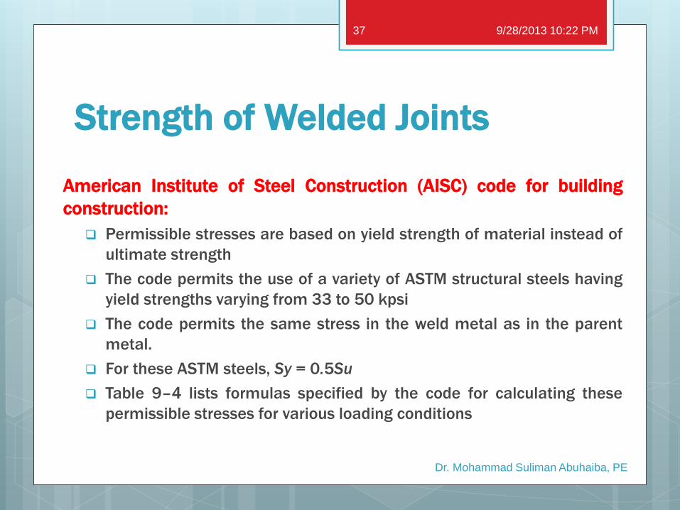
Strength of Welded Joints
American Institute of Steel Construction (AISC) code for building
construction:
Permissible stresses are based on yield strength of material instead of
ultimate strength
The code permits the use of a variety of ASTM structural steels having
yield strengths varying from 33 to 50 kpsi
The code permits the same stress in the weld metal as in the parent
metal.
For these ASTM steels, Sy = 0.5Su
Table 9–4 lists formulas specified by the code for calculating these
permissible stresses for various loading conditions
9/28/2013 10:22 PM
Dr. Mohammad Suliman Abuhaiba, PE
37
Dr. Mohammad Suliman Abuhaiba, PE
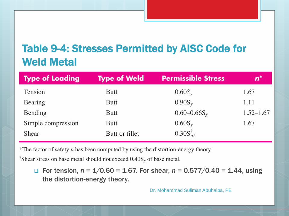
Table 9-4: Stresses Permitted by AISC Code for
Weld Metal
For tension, n = 1/0.60 = 1.67. For shear, n = 0.577/0.40 = 1.44, using
the distortion-energy theory.
Strength of Welded Joints
The electrode material is often the strongest material present.
If a bar of AISI 1010 steel is welded to one of 1018 steel, the weld
metal is actually a mixture of the electrode material and the 1010
and 1018 steels.
A welded cold-drawn bar has its cold-drawn properties replaced
with the hot-rolled properties in the vicinity of the weld.
Check the stresses in the parent metals.
9/28/2013 10:22 PM
Dr. Mohammad Suliman Abuhaiba, PE
39
Strength of Welded Joints
The AISC code, as well as the AWS code, for bridges includes
permissible stresses when fatigue loading is present.
For structures covered by these codes, the actual stresses cannot
exceed the permissible stresses; otherwise the designer is legally
liable.
Codes tend to conceal the actual margin of safety involved.
The fatigue stress-concentration factors listed in Table 9–5 are
suggested for use.
These factors should be used for the parent metal as well as for the
weld metal.
Table 9–6 gives steady-load information and minimum fillet sizes.
9/28/2013 10:22 PM
Dr. Mohammad Suliman Abuhaiba, PE
40
Fatigue Stress-Concentration Factors
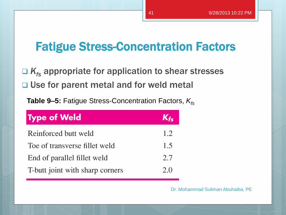
Kfs appropriate for application to shear stresses
Use for parent metal and for weld metal
9/28/2013 10:22 PM
Dr. Mohammad Suliman Abuhaiba, PE
41
Table 9–5: Fatigue Stress-Concentration Factors, Kfs
Dr. Mohammad Suliman Abuhaiba, PE
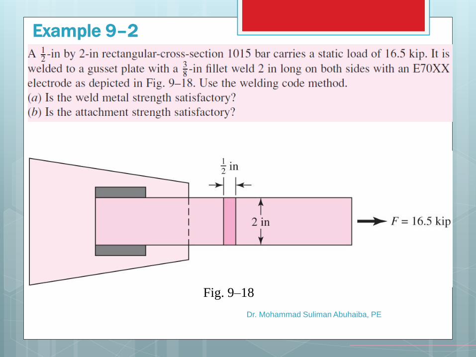
Example 9–2
Fig. 9–18
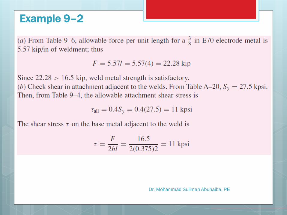
Dr. Mohammad Suliman Abuhaiba, PE
Example 9–2
Dr. Mohammad Suliman Abuhaiba, PE
Example 9–2
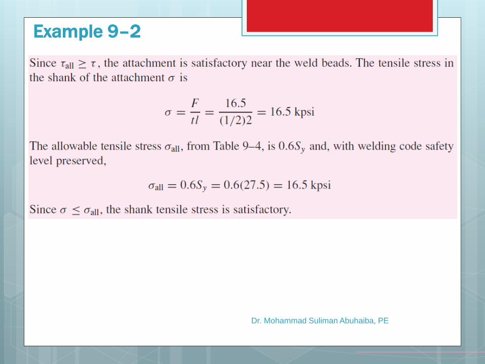
Dr. Mohammad Suliman Abuhaiba, PE
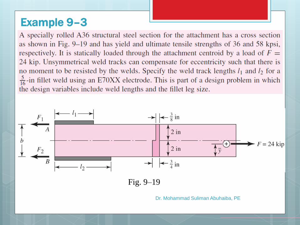
Example 9–3
Fig. 9–19
Dr. Mohammad Suliman Abuhaiba, PE
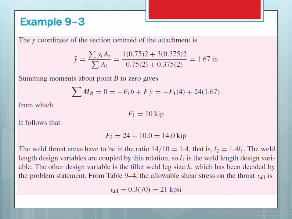
Example 9–3
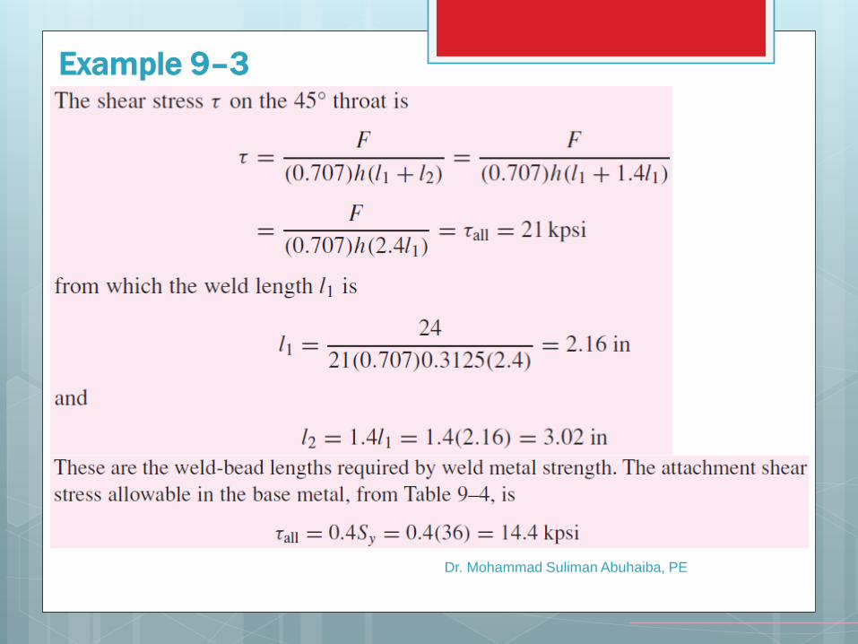
Dr. Mohammad Suliman Abuhaiba, PE
Example 9–3
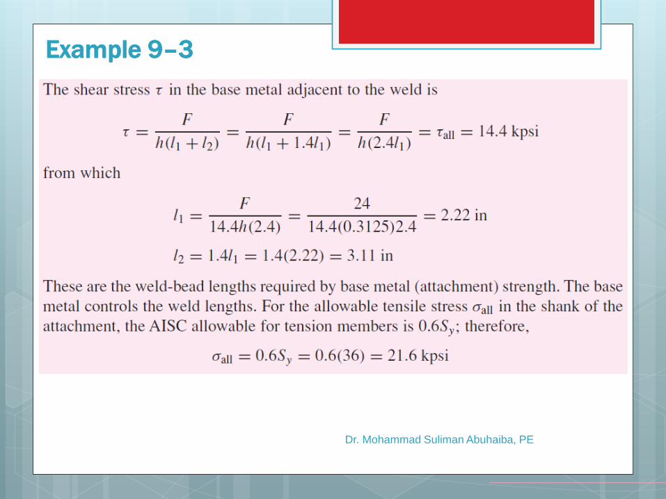
Dr. Mohammad Suliman Abuhaiba, PE
Example 9–3
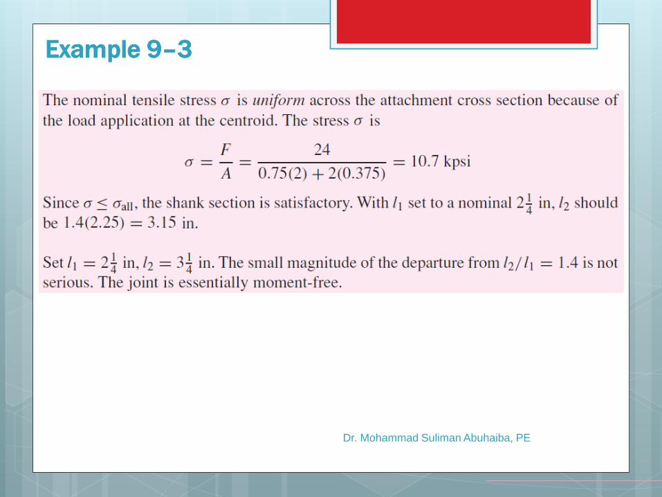
Dr. Mohammad Suliman Abuhaiba, PE
Example 9–3
Dr. Mohammad Suliman Abuhaiba, PE
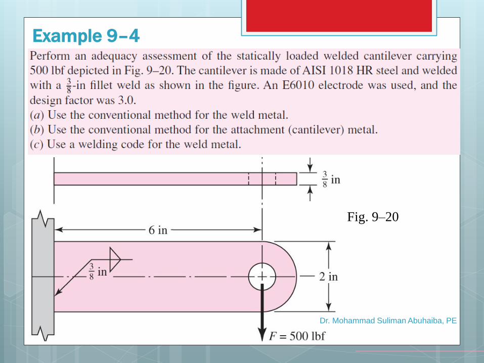
Example 9–4
Fig. 9–20
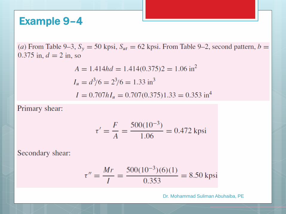
Dr. Mohammad Suliman Abuhaiba, PE
Example 9–4
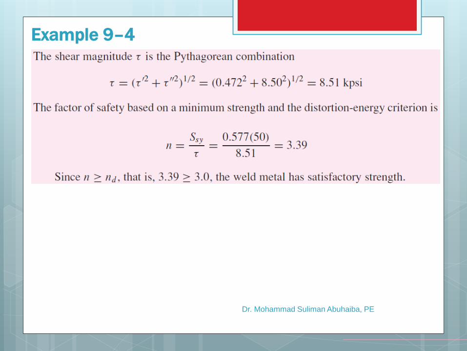
Dr. Mohammad Suliman Abuhaiba, PE
Example 9–4
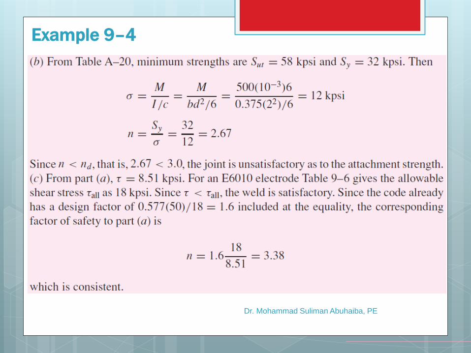
Dr. Mohammad Suliman Abuhaiba, PE
Example 9–4
Dr. Mohammad Suliman Abuhaiba, PE
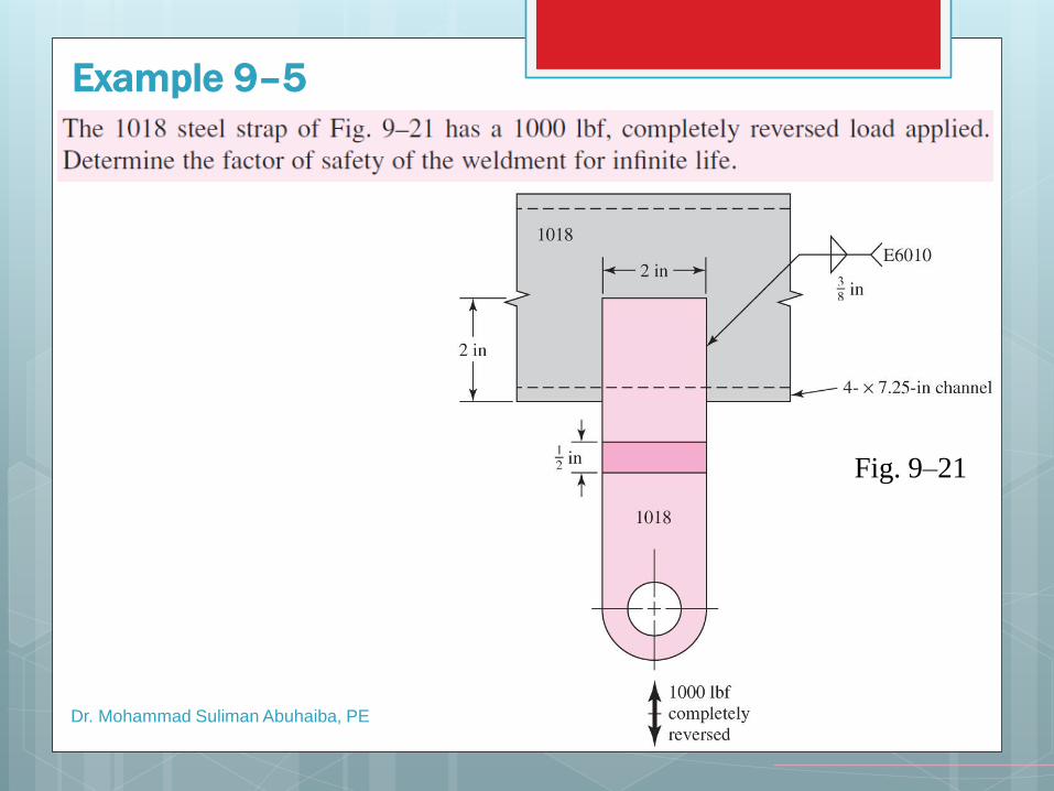
Example 9–5
Fig. 9–21
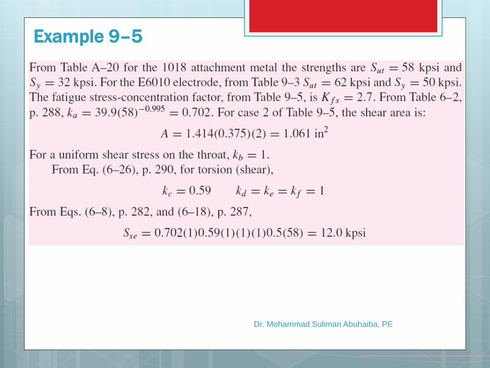
Dr. Mohammad Suliman Abuhaiba, PE
Example 9–5
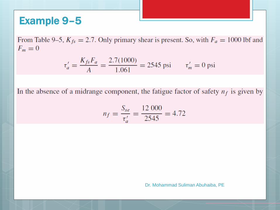
Dr. Mohammad Suliman Abuhaiba, PE
Example 9–5
Dr. Mohammad Suliman Abuhaiba, PE
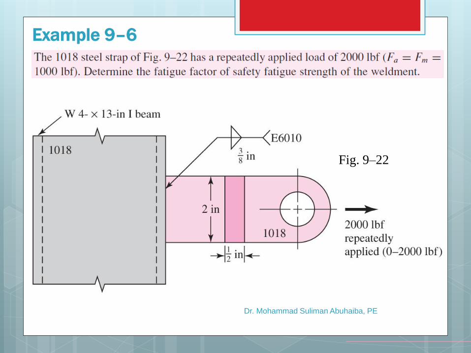
Fig. 9–22
Example 9–6
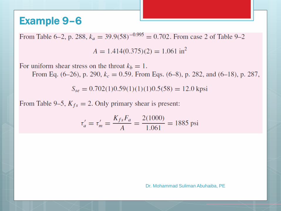
Dr. Mohammad Suliman Abuhaiba, PE
Example 9–6
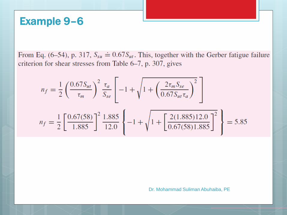
Dr. Mohammad Suliman Abuhaiba, PE
Example 9–6
First Exam
On Tuesday 1/10/2013 at 11:00
Tested Material: Chapter 9
9/28/2013 10:22 PM
Dr. Mohammad Suliman Abuhaiba, PE
60
Practice Problems
1, 5, 9, 16, 20, 24,
28, 34, 45, 51
9/28/2013 10:22 PM
Dr. Mohammad Suliman Abuhaiba, PE
61