Embed Size (px)
Citation preview
1
IAEAInternational Atomic Energy Agency
This set of 189 slides is based on Chapter 9 authored by
P. Andreo, J.P. Seuntjens, and E.B. Podgorsak
of the IAEA publication (ISBN 92-0-107304-6):
Radiation Oncology Physics:
A Handbook for Teachers and Students
Objective:
To familiarize students with basic principles of radiation dosimetry.
Chapter 9
Calibration of Photon and Electron Beams
Slide set prepared in 2006 (updated Aug2007)
by E.B. Podgorsak (McGill University, Montreal)
Comments to S. Vatnitsky:
IAEA Radiation Oncology Physics: A Handbook for Teachers and Students - 9.(2/189)
CHAPTER 9. TABLE OF CONTENTS
9.1. Introduction
9.2. Ionization chamber based dosimetry
9.3. Corrections for influence quantities
9.4. Determination of dose using calibrated chambers
9.5. Stopping power ratios
9.6. Mass-energy absorption coefficient ratios
9.7. Perturbation correction factors
9.8. Beam quality specification
9.9. Calibration of MV photon and electron beams
9.10. Kilovoltage dosimetry
9.11. Error and uncertainty analysis for ionization chambers
2
IAEA Radiation Oncology Physics: A Handbook for Teachers and Students - 9.1 Slide 1 (3/189)
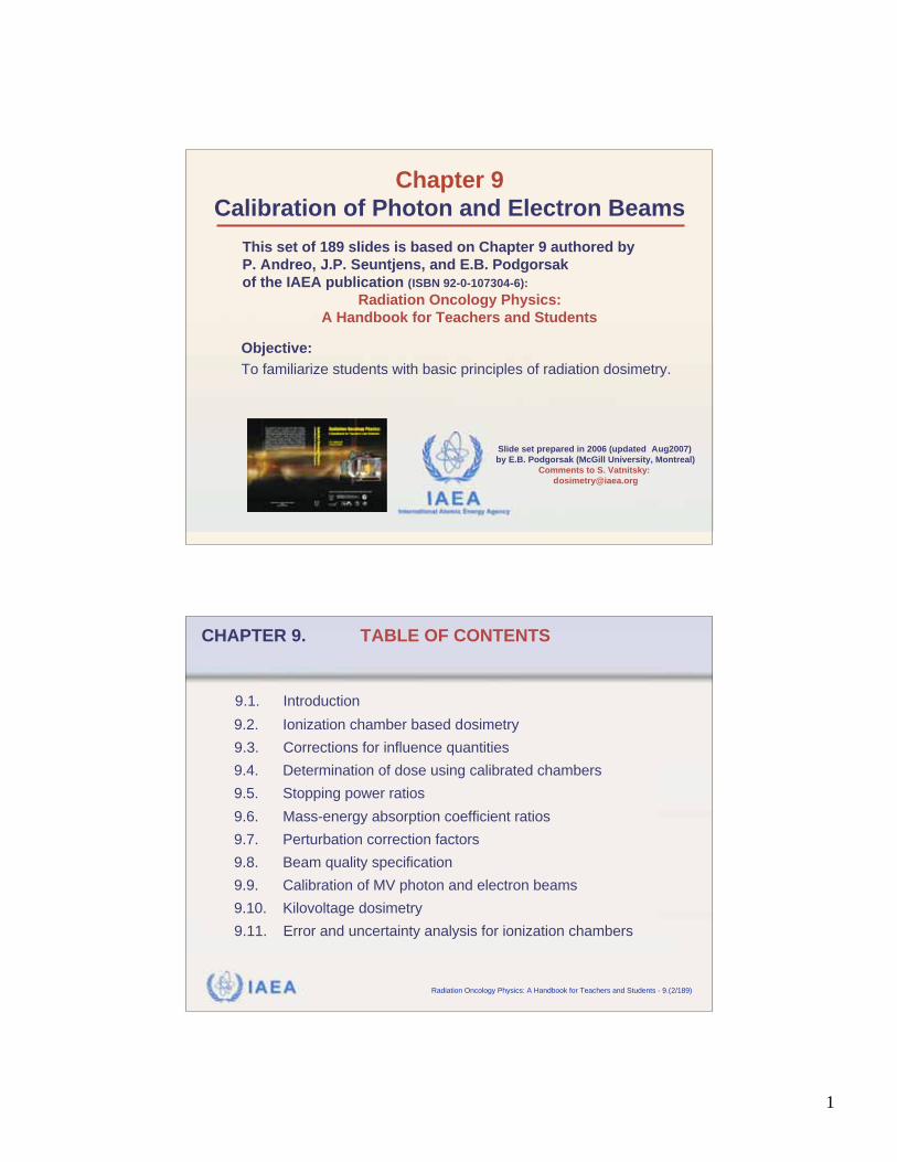
9.1 INTRODUCTION
Modern radiotherapy relies on accurate dose delivery to
the prescribed target volume.
ICRU recommends an overall accuracy in tumour dose
delivery of 5%, based on:
• An analysis of dose response data.
• An evaluation of errors in dose delivery in a clinical setting.
Considering all uncertainties involved in the dose delivery
to the patient, the 5% accuracy is by no means easy to
attain.
±
±
IAEA Radiation Oncology Physics: A Handbook for Teachers and Students - 9.1 Slide 2 (4/189)
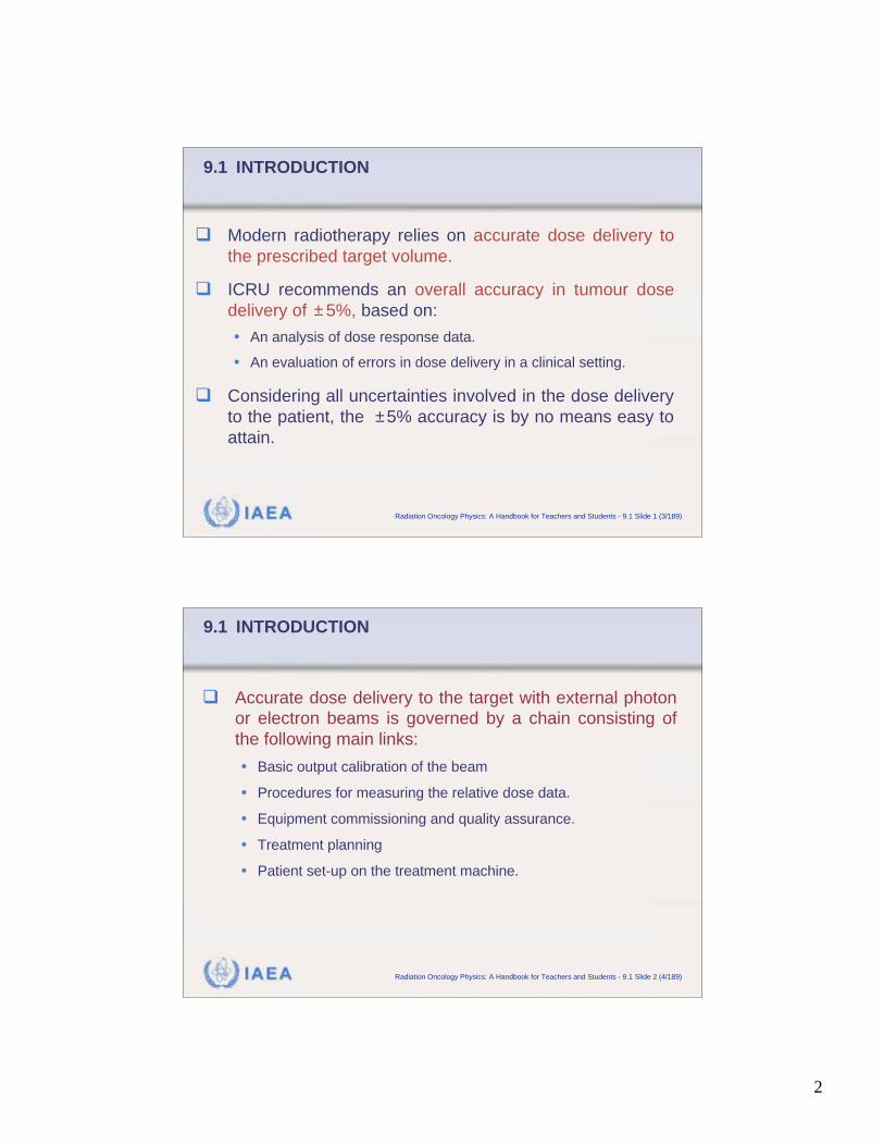
9.1 INTRODUCTION
Accurate dose delivery to the target with external photon
or electron beams is governed by a chain consisting of
the following main links:
• Basic output calibration of the beam
• Procedures for measuring the relative dose data.
• Equipment commissioning and quality assurance.
• Treatment planning
• Patient set-up on the treatment machine.
3
IAEA Radiation Oncology Physics: A Handbook for Teachers and Students - 9.1 Slide 3 (5/189)
9.1 INTRODUCTION
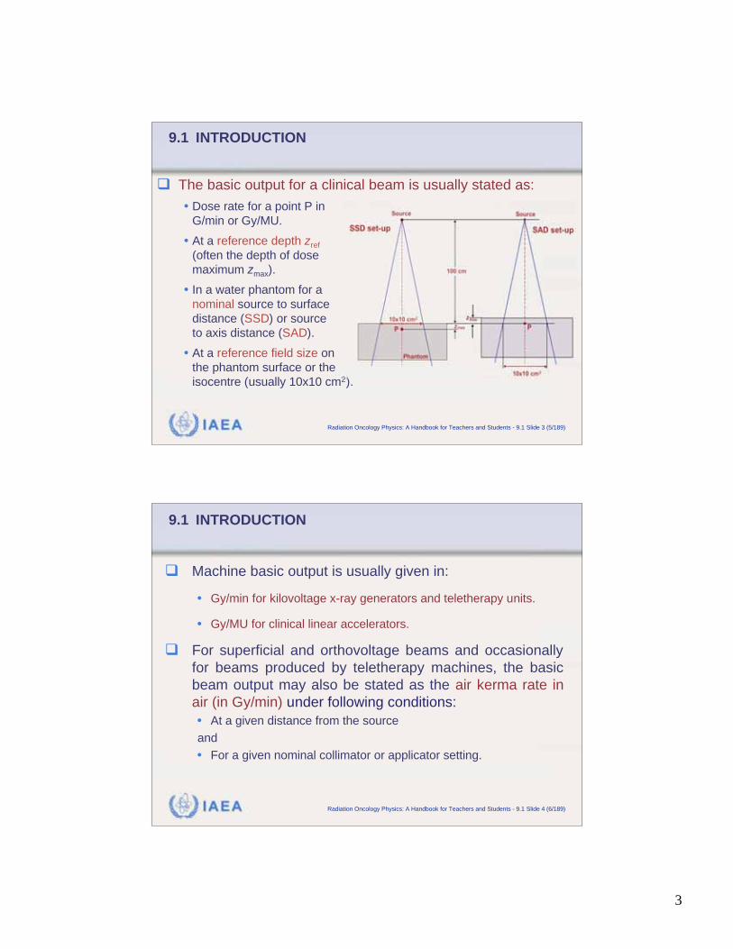
The basic output for a clinical beam is usually stated as:
• Dose rate for a point P in
G/min or Gy/MU.
• At a reference depth zref
(often the depth of dose
maximum zmax).
• In a water phantom for a
nominal source to surface
distance (SSD) or source
to axis distance (SAD).
• At a reference field size on
the phantom surface or the
isocentre (usually 10x10 cm2).
IAEA Radiation Oncology Physics: A Handbook for Teachers and Students - 9.1 Slide 4 (6/189)
9.1 INTRODUCTION
Machine basic output is usually given in:
• Gy/min for kilovoltage x-ray generators and teletherapy units.
• Gy/MU for clinical linear accelerators.
For superficial and orthovoltage beams and occasionally
for beams produced by teletherapy machines, the basic
beam output may also be stated as the air kerma rate in
air (in Gy/min) under following conditions:
• At a given distance from the source
and
• For a given nominal collimator or applicator setting.
4
IAEA Radiation Oncology Physics: A Handbook for Teachers and Students - 9.1 Slide 5 (7/189)
9.1 INTRODUCTION
The basic output calibration for photon and electron beams
is carried out with:
• Radiation dosimeters
• Special dosimetry techniques.
Radiation dosimetry refers to a determination by measure-
ment and/or calculation of:
• Absorbed dose
OR
• Some other physically relevant quantity, such as air kerma, fluence
or equivalent dose
at a given point in the medium.
IAEA Radiation Oncology Physics: A Handbook for Teachers and Students - 9.1 Slide 6 (8/189)
9.1 INTRODUCTION
Radiation dosimeter is defined as any device that is
capable of providing a reading M that is a measure of
the dose D deposited in the dosimeter’s sensitive
volume V by ionizing radiation.
Two categories of dosimeters are known:
• Absolute dosimeter produces a signal from which the dose in its
sensitive volume can be determined without requiring calibration
in a known radiation field.
• Relative dosimeter requires calibration of its signal in a known
radiation field.
5
IAEA Radiation Oncology Physics: A Handbook for Teachers and Students - 9.1 Slide 7 (9/189)
9.1 INTRODUCTION
Basic output calibration of a clinical radiation beam, by
virtue of a direct determination of dose or dose rate in
water under specific reference conditions, is referred to
as reference dosimetry.
Three types of reference dosimetry technique are known:
• Calorimetry
• Fricke (chemical, ferrous sulfate) dosimetry
• Ionization chamber dosimetry
IAEA Radiation Oncology Physics: A Handbook for Teachers and Students - 9.1.1 Slide 1 (10/189)
9.1 INTRODUCTION9.1.1 Calorimetry
Calorimetric dosimetry is the most fundamental of all
reference dosimetry techniques, since it relies on basic
definition of either electrical energy or temperature.
• In principle, calorimetric dosimetry (calorimetry) is simple.
• In practice, calorimetric dosimetry is very complex because of
the need for measuring very small temperature differences.
• This complexity relegates the calorimetry to sophisticated
standards laboratories.
6
IAEA Radiation Oncology Physics: A Handbook for Teachers and Students - 9.1.1 Slide 2 (11/189)
9.1 INTRODUCTION9.1.1 Calorimetry
Main characteristics of calorimetic dosimetry:
• Energy imparted to matter by radiation produces an increase in
temperature
• Dose absorbed in sensitive volume is proportional to
• is measured with thermocouples or thermistors.
• Calorimetric dosimetry is deemed the most precise of all
absolute dosimetry techniques.
T.
T.
T
IAEA Radiation Oncology Physics: A Handbook for Teachers and Students - 9.1.1 Slide 3 (12/189)
9.1 INTRODUCTION9.1.1 Calorimetry
The following simple relationship holds:
• is the average dose in the sensitive volume
• is the thermal capacity of the sensitive volume
• is the thermal defect
• is the temperature increase
Note:
D =
dE
dm=
Cp
T
1
D
C
p
T
T(water, 1 Gy) = 2.4 10 4 K
7
IAEA Radiation Oncology Physics: A Handbook for Teachers and Students - 9.1.1 Slide 4 (13/189)
9.1 INTRODUCTION9.1.1 Calorimetry
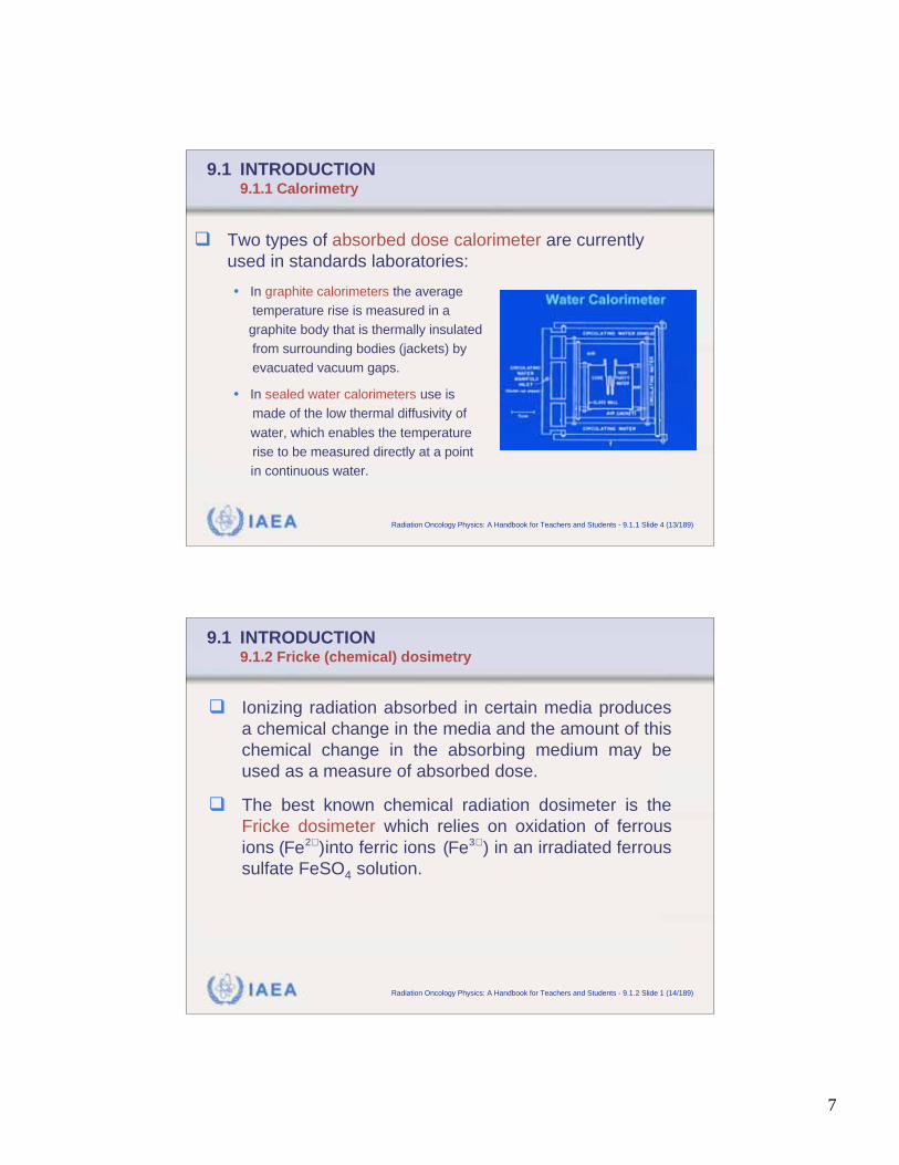
Two types of absorbed dose calorimeter are currently
used in standards laboratories:
• In graphite calorimeters the average
temperature rise is measured in a
graphite body that is thermally insulated
from surrounding bodies (jackets) by
evacuated vacuum gaps.
• In sealed water calorimeters use is
made of the low thermal diffusivity of
water, which enables the temperature
rise to be measured directly at a point
in continuous water.
IAEA Radiation Oncology Physics: A Handbook for Teachers and Students - 9.1.2 Slide 1 (14/189)
9.1 INTRODUCTION9.1.2 Fricke (chemical) dosimetry
Ionizing radiation absorbed in certain media produces
a chemical change in the media and the amount of this
chemical change in the absorbing medium may be
used as a measure of absorbed dose.
The best known chemical radiation dosimeter is the
Fricke dosimeter which relies on oxidation of ferrous
ions into ferric ions in an irradiated ferrous
sulfate FeSO4 solution. (Fe2+ ) (Fe3+ )
8
IAEA Radiation Oncology Physics: A Handbook for Teachers and Students - 9.1.2 Slide 2 (15/189)
9.1 INTRODUCTION9.1.2 Fricke (chemical) dosimetry
Concentration of ferric ions increases proportionally with
dose and is measured with absorption of ultraviolet light
(304 nm) in a spectrophotometer.
Fricke dosimetry depends on an accurate knowledge of
the radiation chemical yield of ferric ions.
The radiation chemical yield G of ferric ions is measured
in moles produced per 1 J of energy absorbed in the
solution.
IAEA Radiation Oncology Physics: A Handbook for Teachers and Students - 9.1.2 Slide 3 (16/189)
9.1 INTRODUCTION9.1.2 Fricke (chemical) dosimetry
An accurate value of the chemical yield G is difficult to
ascertain because the chemical yield is affected by:
• Energy of the radiation
• Dose rate
• Temperature of the solution during irradiation and readout.
Chemical yield in mole/J is related to an older
yield parameter, the G-value in molecules of per
100 eV of absorbed energy:
G(Fe3+ )
Fe3+
1 molecule/J = 1.037 104 mole/J
9
IAEA Radiation Oncology Physics: A Handbook for Teachers and Students - 9.1.2 Slide 4 (17/189)
9.1 INTRODUCTION9.1.2 Fricke (chemical) dosimetry
Average absorbed dose in a Fricke solution is given as:
• is the change in molar concentration of
• is the density of the Fricke solution.
• is the increase in optical density after irradiation.
• is the extinction coefficient.
• is the thickness of the solution.
• is the chemical yield of in mole/J.
D =
M
G(Fe3+ )=
(O.D.)
G(Fe3+ )
= 278 (O.D.)
M
(O.D.)
+3(Fe )G Fe3+
Fe3+
.
IAEA Radiation Oncology Physics: A Handbook for Teachers and Students - 9.1.2 Slide 5 (18/189)
9.1 INTRODUCTION9.1.2 Fricke (chemical) dosimetry
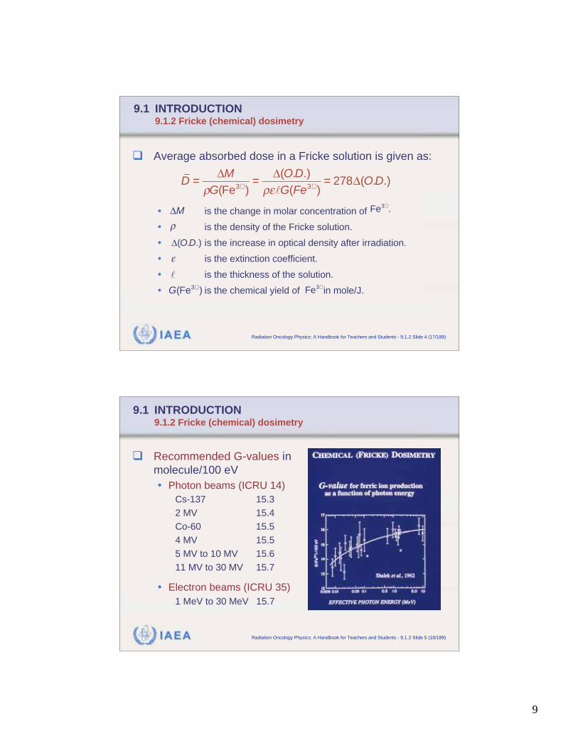
Recommended G-values in
molecule/100 eV
• Photon beams (ICRU 14)
Cs-137 15.3
2 MV 15.4
Co-60 15.5
4 MV 15.5
5 MV to 10 MV 15.6
11 MV to 30 MV 15.7
• Electron beams (ICRU 35)
1 MeV to 30 MeV 15.7
10
IAEA Radiation Oncology Physics: A Handbook for Teachers and Students - 9.1.2 Slide 6 (19/189)
9.1 INTRODUCTION9.1.2 Fricke (chemical) dosimetry
Best G-value for cobalt-60 gamma rays is 15.6 mole-
cules per 100 eV of absorbed energy, corresponding to
a chemical yield of 1.607x10⁻⁶ mole/J.
Typical dynamic range for ferrous sulfate Fricke dosi-
meters is from a few Gy to about 400 Gy.
The relatively large dose required to produce a measur-
able signal makes Fricke dosimetry impractical for
routine use in radiotherapy clinics.
G(Fe3+ )
IAEA Radiation Oncology Physics: A Handbook for Teachers and Students - 9.1.3 Slide 1 (20/189)
9.1 INTRODUCTION9.1.3 Ionization chamber dosimetry
Ionization chamber is the most practical and most widely
used type of dosimeter for accurate measurement of
machine output in radiotherapy.
It may be used as an absolute or relative dosimeter.
Its sensitive volume is usually filled with ambient air and:
• The dose related measured quantity is charge Q,
• The dose rate related measured quantity is current I,
produced by radiation in the chamber sensitive volume.
11
IAEA Radiation Oncology Physics: A Handbook for Teachers and Students - 9.1.3 Slide 2 (21/189)
9.1 INTRODUCTION9.1.3 Ionization chamber dosimetry
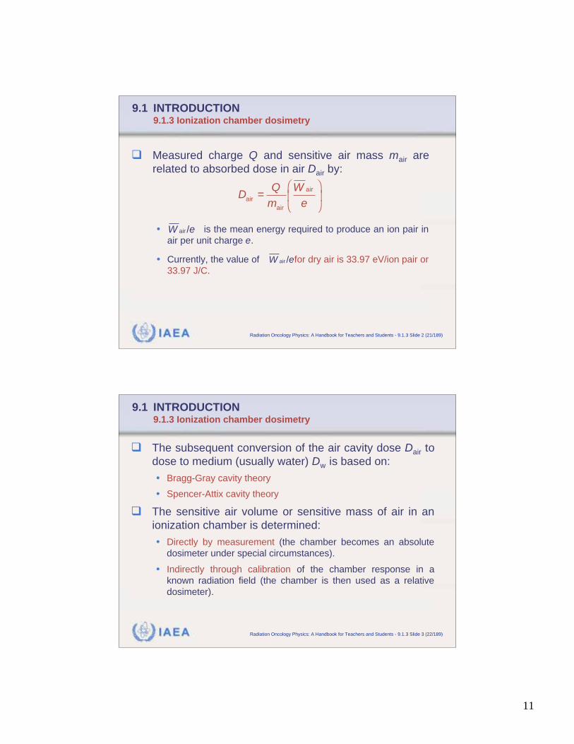
Measured charge Q and sensitive air mass mair are
related to absorbed dose in air Dair by:
• is the mean energy required to produce an ion pair in
air per unit charge e.
• Currently, the value of for dry air is 33.97 eV/ion pair or
33.97 J/C.
air
air
air
Q WD
m e=
air /W e
air /W e
IAEA Radiation Oncology Physics: A Handbook for Teachers and Students - 9.1.3 Slide 3 (22/189)
9.1 INTRODUCTION9.1.3 Ionization chamber dosimetry
The subsequent conversion of the air cavity dose Dair to
dose to medium (usually water) Dw is based on:
• Bragg-Gray cavity theory
• Spencer-Attix cavity theory
The sensitive air volume or sensitive mass of air in an
ionization chamber is determined:
• Directly by measurement (the chamber becomes an absolute
dosimeter under special circumstances).
• Indirectly through calibration of the chamber response in a
known radiation field (the chamber is then used as a relative
dosimeter).
12
IAEA Radiation Oncology Physics: A Handbook for Teachers and Students - 9.1.4 Slide 1 (23/189)
9.1 INTRODUCTION9.1.4 Mean energy expended in air per ion pair formed
It is assumed that a constant value of can be
used for the complete photon and electron energy
range used in radiotherapy dosimetry.
There is no direct experimental support for such an
assumption, as the data available have been obtained
only from measurements with Co-60 and Cs-137
gamma ray beams and 2 MV x ray beams.
W air /e
IAEA Radiation Oncology Physics: A Handbook for Teachers and Students - 9.1.4 Slide 2 (24/189)
9.1 INTRODUCTION9.1.4 Mean energy expended in air per ion pair formed
was determined using two dose measurement
techniques:
• Graphite calorimeter.
• Graphite ionization chamber in a graphite phantom.
The two techniques (graphite calorimeter and graphite
ionization chamber in graphite phantom) for deriving the
absorbed dose to graphite must yield the same dose
value.
W air /e
13
IAEA Radiation Oncology Physics: A Handbook for Teachers and Students - 9.1.4 Slide 3 (25/189)
9.1 INTRODUCTION9.1.4 Mean energy expended in air per ion pair formed
Dose to graphite is given as:
• is the charge Q collected in the chamber sensitive air per
unit mass mair and corrected for influence quantities.
• is the ratio of mass collision stopping powers for graphite
and air calculated for the photon energy used in irradiation.
is given as:
air graphite
calorimeter ionization chamber air
air
Q WD D s
m e=
air/Q m
graphiteairs
W air /e
W air
e=
Dcalorimeter
Q
mair
sair
graphite
IAEA Radiation Oncology Physics: A Handbook for Teachers and Students - 9.1.4 Slide 5 (26/189)
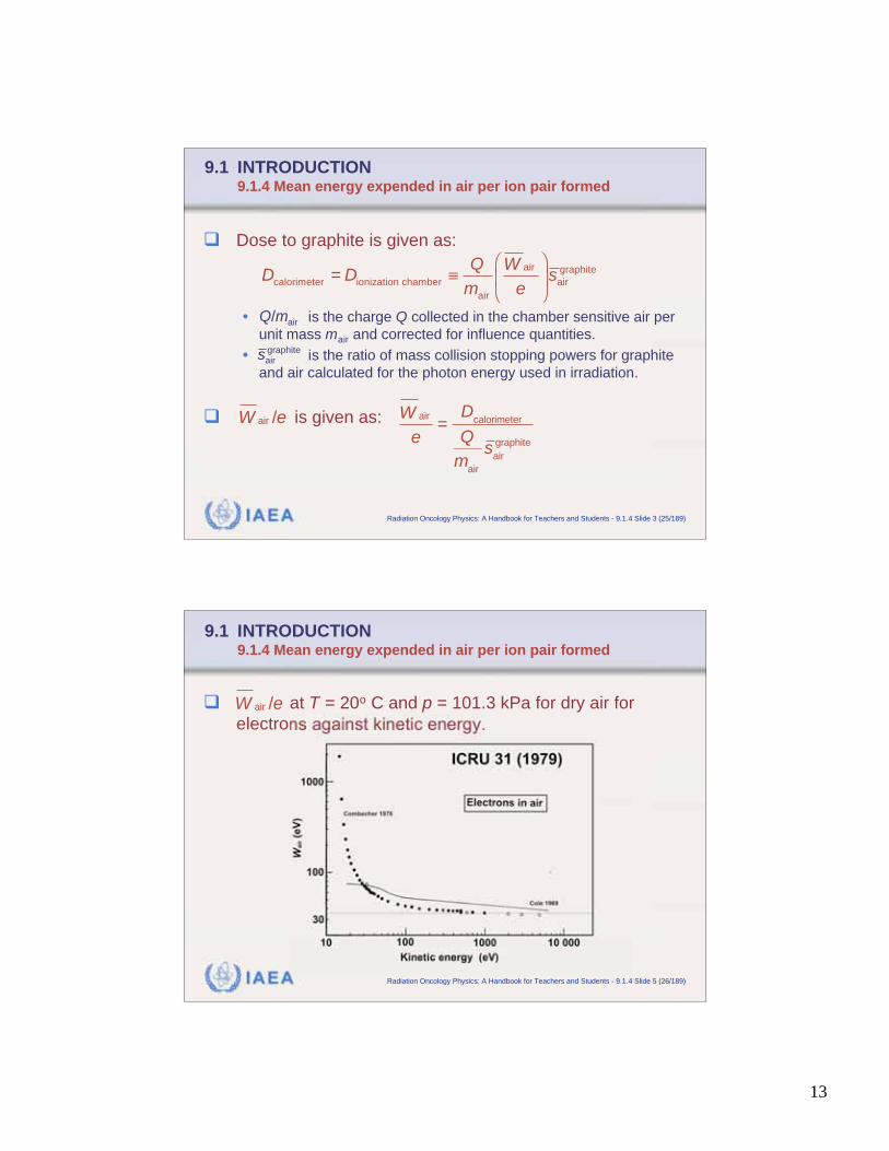
9.1 INTRODUCTION9.1.4 Mean energy expended in air per ion pair formed
at T = 20o C and p = 101.3 kPa for dry air for
electrons against kinetic energy. W air /e
14
IAEA Radiation Oncology Physics: A Handbook for Teachers and Students - 9.1.4 Slide 6 (27/189)
9.1 INTRODUCTION9.1.4 Mean energy expended in air per ion pair formed
depends on relative humidity of air:
• For air at relative humidity of 50%,
• For dry air,
At air temperature T = 20oC and pressure p = 101.3 kPa
for the same amount of energy available for creating
charge in air, 0.6% more charge will be created in air at
50% relative humidity than in dry air.
W air /e
=air( / ) 33.77 J/CW e
=air( / ) 33.97 J/CW e
IAEA Radiation Oncology Physics: A Handbook for Teachers and Students - 9.1.5 Slide 1 (28/189)
9.1 INTRODUCTION9.1.5 Reference dosimetry with ionization chambers
Three types of ionization chamber may be used in refer-
ence dosimetry as absolute dosimeter:
• Standard free air ionization chamber
• Cavity ionization chamber
• Extrapolation chamber
The “absoluteness” of dose determination with ionization
chambers depends on the accurate knowledge of
the mean energy required to produce an ion pair in air.air / ,W e
15
IAEA Radiation Oncology Physics: A Handbook for Teachers and Students - 9.1.5 Slide 1 (29/189)
9.1 INTRODUCTION9.1.5 Reference dosimetry with ionization chambers
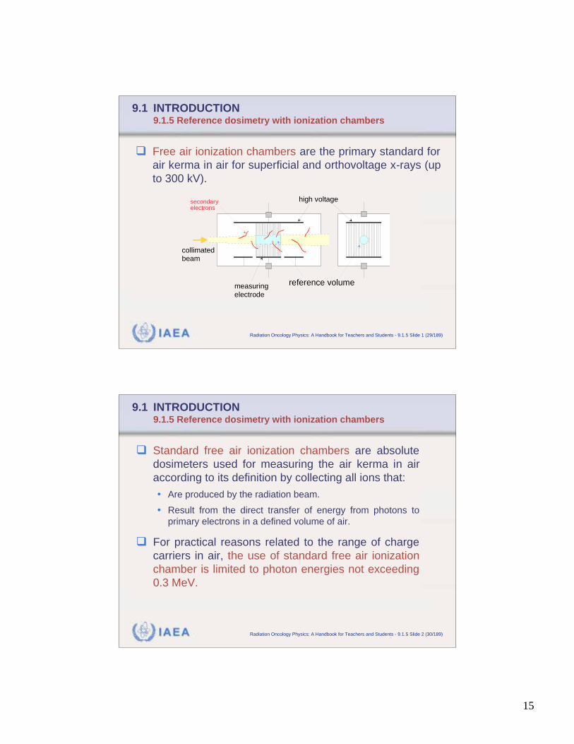
Free air ionization chambers are the primary standard for
air kerma in air for superficial and orthovoltage x-rays (up
to 300 kV).
reference volume
high voltage
measuringelectrode
collimatedbeam
secondaryelectrons
IAEA Radiation Oncology Physics: A Handbook for Teachers and Students - 9.1.5 Slide 2 (30/189)
9.1 INTRODUCTION9.1.5 Reference dosimetry with ionization chambers
Standard free air ionization chambers are absolute
dosimeters used for measuring the air kerma in air
according to its definition by collecting all ions that:
• Are produced by the radiation beam.
• Result from the direct transfer of energy from photons to
primary electrons in a defined volume of air.
For practical reasons related to the range of charge
carriers in air, the use of standard free air ionization
chamber is limited to photon energies not exceeding
0.3 MeV.
16
IAEA Radiation Oncology Physics: A Handbook for Teachers and Students - 9.1.5 Slide 3 (31/189)
9.1 INTRODUCTION9.1.5 Reference dosimetry with ionization chambers
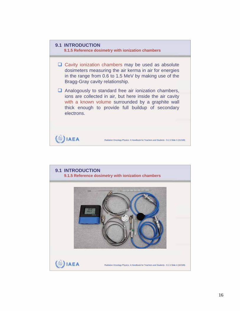
Cavity ionization chambers may be used as absolute
dosimeters measuring the air kerma in air for energies
in the range from 0.6 to 1.5 MeV by making use of the
Bragg-Gray cavity relationship.
Analogously to standard free air ionization chambers,
ions are collected in air, but here inside the air cavity
with a known volume surrounded by a graphite wall
thick enough to provide full buildup of secondary
electrons.
IAEA Radiation Oncology Physics: A Handbook for Teachers and Students - 9.1.5 Slide 4 (32/189)
9.1 INTRODUCTION9.1.5 Reference dosimetry with ionization chambers
17
IAEA Radiation Oncology Physics: A Handbook for Teachers and Students - 9.1.5 Slide 5 (33/189)
9.1 INTRODUCTION9.1.5 Reference dosimetry with ionization chambers
Phantom-embedded extrapolation chambers are:
• uncalibrated,
• variable air volume,
extrapolation chambers built as integral part of a water
equivalent phantom in which the dose is measured.
Phantom-embedded extrapolation chambers can serve
as absolute radiation dosimeters in the measurement of
absorbed dose for megavoltage photon and electron
beams.
IAEA Radiation Oncology Physics: A Handbook for Teachers and Students - 9.1.5 Slide 6 (34/189)
9.1 INTRODUCTION9.1.5 Reference dosimetry with ionization chambers
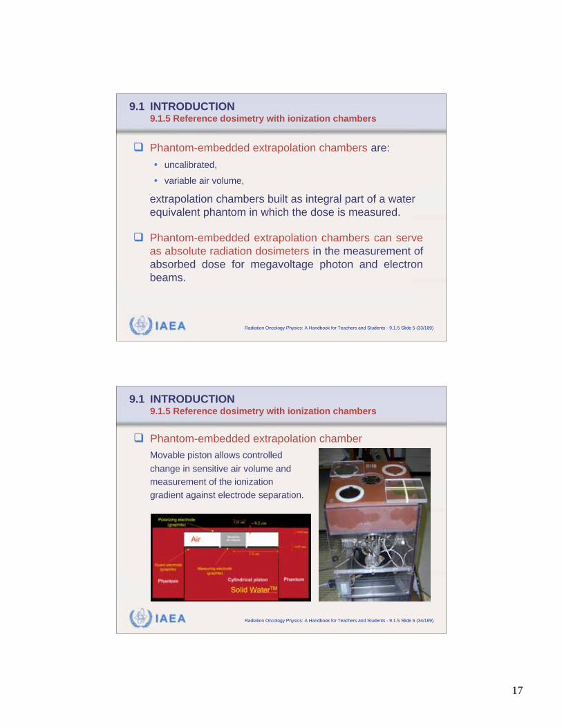
Phantom-embedded extrapolation chamber
Movable piston allows controlled
change in sensitive air volume and
measurement of the ionization
gradient against electrode separation.
18
IAEA Radiation Oncology Physics: A Handbook for Teachers and Students - 9.1.5 Slide 7 (35/189)
9.1 INTRODUCTION9.1.5 Reference dosimetry with ionization chambers
Standard dosimetry protocols are based on the Bragg-
Gray or Spencer-Attix cavity theories which provide a
simple linear relationship between the dose at a given
point in the medium and the ratio Q/mair.
In extrapolation chambers, the ratio Q/mair is constant
and may be replaced in the cavity relationship by the
derivative dQ/dmair which can be measured accurately
through controlled variation in the electrode separation.
IAEA Radiation Oncology Physics: A Handbook for Teachers and Students - 9.1.6 Slide 1 (36/189)
9.1 INTRODUCTION9.1.6 Clinical beam calibration and measurement chain
Clinical photon and electron beams are most commonly
calibrated with ionization chambers that:
• Are used as relative dosimeters.
• Have calibration coefficients determined either in air or in water
and are traceable to a national primary standards dosimetry
laboratory (PSDL).
Chamber calibration coefficient essentially obviates the
need for an accurate knowledge of the chamber sensitive
volume.
19
IAEA Radiation Oncology Physics: A Handbook for Teachers and Students - 9.1.6 Slide 2 (37/189)
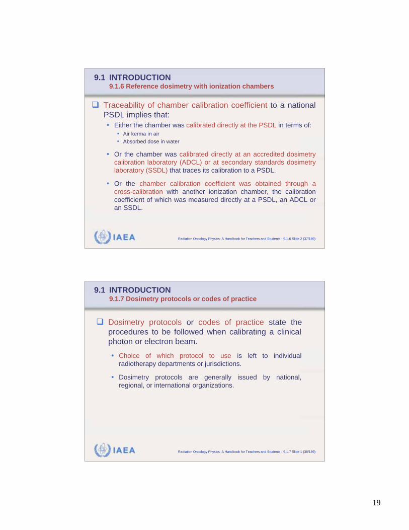
9.1 INTRODUCTION9.1.6 Reference dosimetry with ionization chambers
Traceability of chamber calibration coefficient to a national
PSDL implies that:
• Either the chamber was calibrated directly at the PSDL in terms of:
• Air kerma in air
• Absorbed dose in water
• Or the chamber was calibrated directly at an accredited dosimetry
calibration laboratory (ADCL) or at secondary standards dosimetry
laboratory (SSDL) that traces its calibration to a PSDL.
• Or the chamber calibration coefficient was obtained through a
cross-calibration with another ionization chamber, the calibration
coefficient of which was measured directly at a PSDL, an ADCL or
an SSDL.
IAEA Radiation Oncology Physics: A Handbook for Teachers and Students - 9.1.7 Slide 1 (38/189)
9.1 INTRODUCTION9.1.7 Dosimetry protocols or codes of practice
Dosimetry protocols or codes of practice state the
procedures to be followed when calibrating a clinical
photon or electron beam.
• Choice of which protocol to use is left to individual
radiotherapy departments or jurisdictions.
• Dosimetry protocols are generally issued by national,
regional, or international organizations.
20
IAEA Radiation Oncology Physics: A Handbook for Teachers and Students - 9.1.7 Slide 2 (39/189)
9.1 INTRODUCTION9.1.7 Dosimetry protocols or codes of practice
Examples of dosimetry protocols:
• National:
• Institute of Physics and Engineering in Medicine and Biology (IPEMB) for UK
• Deutsches Institut fuer Normung (DIN) for Germany
• Regional:
• American Association of Physicists in Medicine (AAPM) for North America
• Nederlandse Commissie voor Stralingsdosimetrie (NCS) for Netherlands and
Belgium
• Nordic Association of Clinical Physics (NACP) for Scandinavia
IAEA Radiation Oncology Physics: A Handbook for Teachers and Students - 9.1.7 Slide 3 (40/189)
9.1 INTRODUCTION9.1.7 Dosimetry protocols or codes of practice
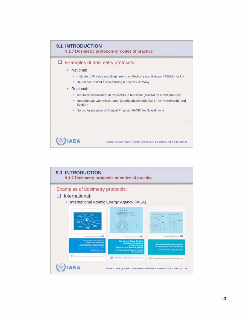
Examples of dosimetry protocols:
International:
• International Atomic Energy Agency (IAEA)
21
IAEA Radiation Oncology Physics: A Handbook for Teachers and Students - 9.2 Slide 1 (41/189)
9.2 IONIZATION CHAMBER BASED DOSIMETRY SYSTEMS
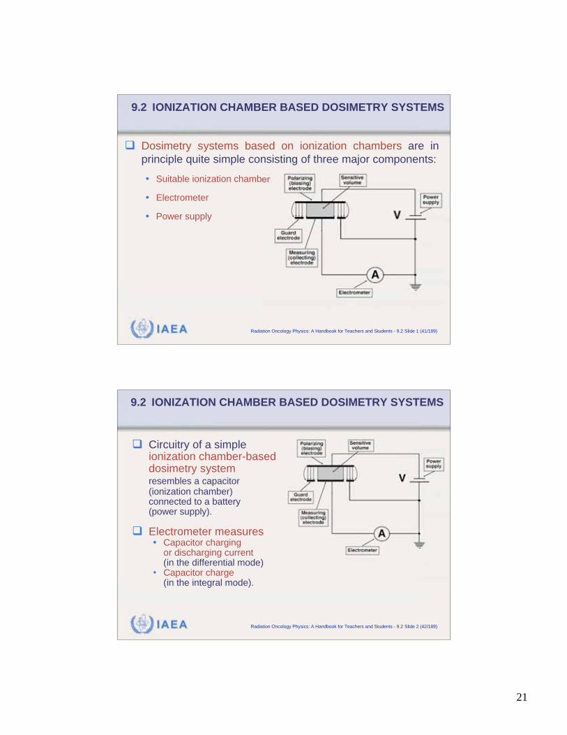
Dosimetry systems based on ionization chambers are in
principle quite simple consisting of three major components:
• Suitable ionization chamber
• Electrometer
• Power supply
IAEA Radiation Oncology Physics: A Handbook for Teachers and Students - 9.2 Slide 2 (42/189)
9.2 IONIZATION CHAMBER BASED DOSIMETRY SYSTEMS
Circuitry of a simpleionization chamber-baseddosimetry systemresembles a capacitor(ionization chamber)connected to a battery(power supply).
Electrometer measures• Capacitor charging
or discharging current(in the differential mode)
• Capacitor charge(in the integral mode).
22
IAEA Radiation Oncology Physics: A Handbook for Teachers and Students - 9.2.1 Slide 1 (43/189)
9.2 IONIZATION CHAMBER BASED DOSIMETRY SYSTEMS9.2.1 Ionization chambers
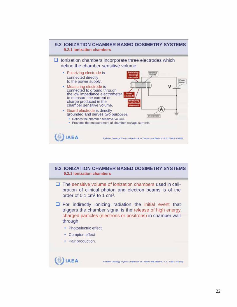
Ionization chambers incorporate three electrodes which
define the chamber sensitive volume:
• Polarizing electrode is
connected directlyto the power supply.
• Measuring electrode isconnected to ground throughthe low impedance electrometerto measure the current orcharge produced in thechamber sensitive volume.
• Guard electrode is directlygrounded and serves two purposes• Defines the chamber sensitive volume
• Prevents the measurement of chamber leakage currents
IAEA Radiation Oncology Physics: A Handbook for Teachers and Students - 9.2.1 Slide 2 (44/189)
9.2 IONIZATION CHAMBER BASED DOSIMETRY SYSTEMS9.2.1 Ionization chambers
The sensitive volume of ionization chambers used in cali-
bration of clinical photon and electron beams is of the
order of 0.1 cm3 to 1 cm3.
For indirectly ionizing radiation the initial event that
triggers the chamber signal is the release of high energy
charged particles (electrons or positrons) in chamber wall
through:
• Photoelectric effect
• Compton effect
• Pair production.
23
IAEA Radiation Oncology Physics: A Handbook for Teachers and Students - 9.2.1 Slide 3 (45/189)
9.2 IONIZATION CHAMBER BASED DOSIMETRY SYSTEMS9.2.1 Ionization chambers
Air is usually used as the sensitive gas in an ionization
chamber.
Some of the electrons released in the chamber wall enter
the chamber sensitive volume and ionize the air through
Coulomb interactions with the air molecules producing
low energy electrons and positive ions.
IAEA Radiation Oncology Physics: A Handbook for Teachers and Students - 9.2.1 Slide 4 (46/189)
9.2 IONIZATION CHAMBER BASED DOSIMETRY SYSTEMS9.2.1 Ionization chambers
In air, since oxygen is an electronegative gas, the low
energy electrons produced by high-energy electrons
interacting with air molecules, attach themselves to
oxygen molecules and form negative ions.
In standard air-filled ionization chambers, positive ions
and negative ions are collected, rather than positive
ions and free electrons.
24
IAEA Radiation Oncology Physics: A Handbook for Teachers and Students - 9.2.1 Slide 5 (47/189)
9.2 IONIZATION CHAMBER BASED DOSIMETRY SYSTEMS9.2.1 Ionization chambers
Electronegativity is a measure of the ability of an atomor molecule to attract electrons to form a negative ion.
• Pauling scale ranging from 0.7 for cesium and francium (theleast electronegative atoms) to 4 for fluorine (the most electro-negative atom) is used to describe the level of electronegativity.
• Because oxygen is a strong electronegative atom, in air basedionization chambers, charged particles collected in chamberelectrodes are positive and negative ions, rather than positiveions and free electrons.
IAEA Radiation Oncology Physics: A Handbook for Teachers and Students - 9.2.1 Slide 6 (48/189)
9.2 IONIZATION CHAMBER BASED DOSIMETRY SYSTEMS9.2.1 Ionization chambers
Two types of ionization chamber are used for calibration:
• Cylindrical (also called thimble) chambers are used in calibration of:
• Orthovoltage x-ray beams.
• Megavoltage x-ray beams.
• Electron beams with energies of 10 MeV and above.
• Parallel-plate (also called end window or plane-parallel) chambers
are used in calibration of:
• Superficial x-ray beams.
• Electron beams with energies below 10 MeV.
• Photon beams in the buildup region and surface dose.
25
IAEA Radiation Oncology Physics: A Handbook for Teachers and Students - 9.2.1 Slide 7 (49/189)
9.2 IONIZATION CHAMBER BASED DOSIMETRY SYSTEMS9.2.1 Ionization chambers
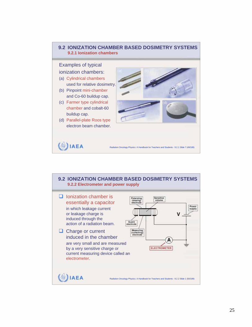
Examples of typical
ionization chambers:
(a) Cylindrical chambers
used for relative dosimetry.
(b) Pinpoint mini-chamber
and Co-60 buildup cap.
(c) Farmer type cylindrical
chamber and cobalt-60
buildup cap.
(d) Parallel-plate Roos type
electron beam chamber.
IAEA Radiation Oncology Physics: A Handbook for Teachers and Students - 9.2.2 Slide 1 (50/189)
9.2 IONIZATION CHAMBER BASED DOSIMETRY SYSTEMS9.2.2 Electrometer and power supply
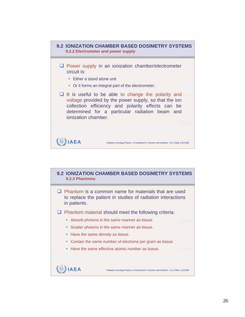
Ionization chamber is
essentially a capacitor
in which leakage current
or leakage charge is
induced through the
action of a radiation beam.
Charge or current
induced in the chamber
are very small and are measured
by a very sensitive charge or
current measuring device called an
electrometer.
26
IAEA Radiation Oncology Physics: A Handbook for Teachers and Students - 9.2.2 Slide 2 (51/189)
9.2 IONIZATION CHAMBER BASED DOSIMETRY SYSTEMS9.2.2 Electrometer and power supply
Power supply in an ionization chamber/electrometer
circuit is:
• Either a stand alone unit
• Or it forms an integral part of the electrometer.
It is useful to be able to change the polarity and
voltage provided by the power supply, so that the ion
collection efficiency and polarity effects can be
determined for a particular radiation beam and
ionization chamber.
IAEA Radiation Oncology Physics: A Handbook for Teachers and Students - 9.2.3 Slide 1 (52/189)
9.2 IONIZATION CHAMBER BASED DOSIMETRY SYSTEMS9.2.3 Phantoms
Phantom is a common name for materials that are used
to replace the patient in studies of radiation interactions
in patients.
Phantom material should meet the following criteria:
• Absorb photons in the same manner as tissue.
• Scatter photons in the same manner as tissue.
• Have the same density as tissue.
• Contain the same number of electrons per gram as tissue.
• Have the same effective atomic number as tissue.
27
IAEA Radiation Oncology Physics: A Handbook for Teachers and Students - 9.2.3 Slide 2 (53/189)
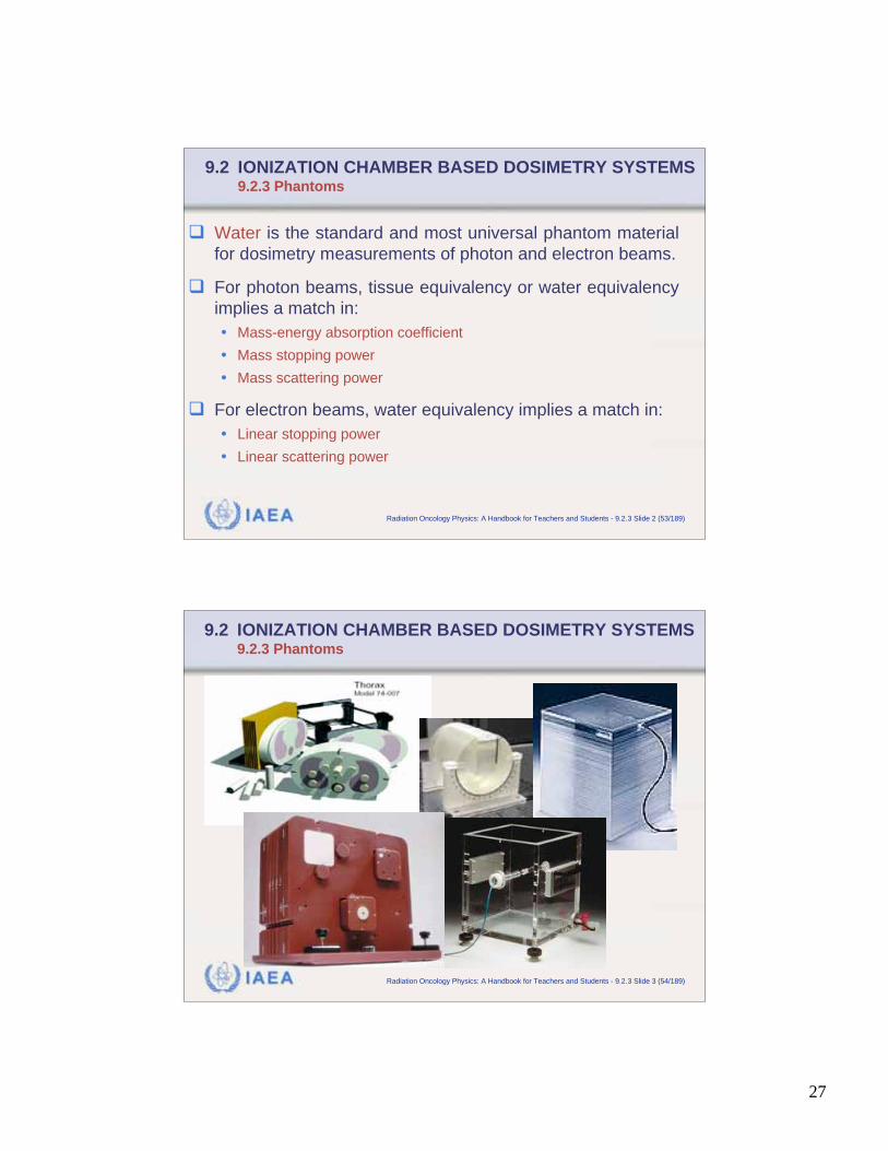
9.2 IONIZATION CHAMBER BASED DOSIMETRY SYSTEMS9.2.3 Phantoms
Water is the standard and most universal phantom material
for dosimetry measurements of photon and electron beams.
For photon beams, tissue equivalency or water equivalency
implies a match in:
• Mass-energy absorption coefficient
• Mass stopping power
• Mass scattering power
For electron beams, water equivalency implies a match in:
• Linear stopping power
• Linear scattering power
IAEA Radiation Oncology Physics: A Handbook for Teachers and Students - 9.2.3 Slide 3 (54/189)
9.2 IONIZATION CHAMBER BASED DOSIMETRY SYSTEMS9.2.3 Phantoms
28
IAEA Radiation Oncology Physics: A Handbook for Teachers and Students - 9.2.3 Slide 4 (55/189)
9.2 IONIZATION CHAMBER BASED DOSIMETRY SYSTEMS9.2.3 Phantoms
Common plastic phantom materials used in dosimetry
measurements are:
• Polystyrene (density: 0.96 to 1.04 g/cm3)
• Lucite (also called acrylic, plexiglass, polymethylmethacrylate,
PMMA) with density of 1.18 g/cm3.
• A-150 tissue equivalent plastic
• Solid Water
• Plastic water
• Virtual water
IAEA Radiation Oncology Physics: A Handbook for Teachers and Students - 9.2.3 Slide 5 (56/189)
9.2 IONIZATION CHAMBER BASED DOSIMETRY SYSTEMS9.2.3 Phantoms
Plastic solid phantom materials are not universal
tissue substitutes, since not all required equivalency
parameters for plastics can be matched adequately
with those of water.
Effective atomic number Zeff of a phantom material
depends upon:
• Atomic composition of the phantom material.
• Type of the radiation beam.
• Quality of the radiation beam.
29
IAEA Radiation Oncology Physics: A Handbook for Teachers and Students - 9.2.3 Slide 6 (57/189)
9.2 IONIZATION CHAMBER BASED DOSIMETRY SYSTEMS9.2.3 Phantoms
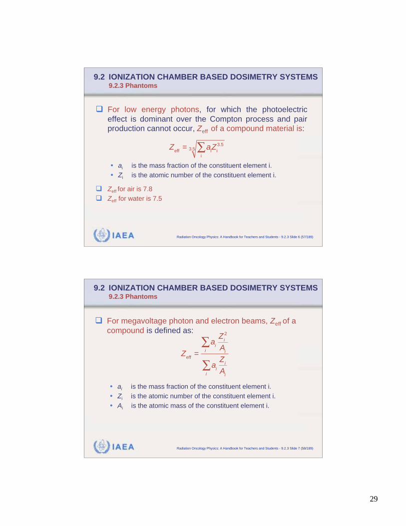
For low energy photons, for which the photoelectric
effect is dominant over the Compton process and pair
production cannot occur, Zeff of a compound material is:
• ai is the mass fraction of the constituent element i.
• Zi is the atomic number of the constituent element i.
Zeff for air is 7.8
Zeff for water is 7.5
Zeff
= aiZ
i
3.5
i
3.5
IAEA Radiation Oncology Physics: A Handbook for Teachers and Students - 9.2.3 Slide 7 (58/189)
9.2 IONIZATION CHAMBER BASED DOSIMETRY SYSTEMS9.2.3 Phantoms
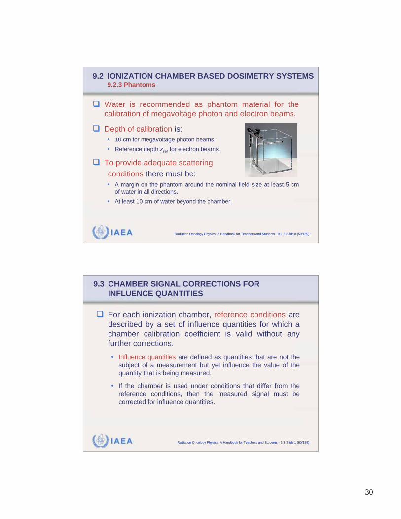
For megavoltage photon and electron beams, Zeff of a
compound is defined as:
• ai is the mass fraction of the constituent element i.
• Zi is the atomic number of the constituent element i.
• Ai is the atomic mass of the constituent element i.
Zeff
=
ai
Zi
2
Aii
ai
Zi
Aii
30
IAEA Radiation Oncology Physics: A Handbook for Teachers and Students - 9.2.3 Slide 8 (59/189)
9.2 IONIZATION CHAMBER BASED DOSIMETRY SYSTEMS9.2.3 Phantoms
Water is recommended as phantom material for the
calibration of megavoltage photon and electron beams.
Depth of calibration is:
• 10 cm for megavoltage photon beams.
• Reference depth zref for electron beams.
To provide adequate scattering
conditions there must be:
• A margin on the phantom around the nominal field size at least 5 cm
of water in all directions.
• At least 10 cm of water beyond the chamber.
IAEA Radiation Oncology Physics: A Handbook for Teachers and Students - 9.3 Slide 1 (60/189)
9.3 CHAMBER SIGNAL CORRECTIONS FOR
INFLUENCE QUANTITIES
For each ionization chamber, reference conditions are
described by a set of influence quantities for which a
chamber calibration coefficient is valid without any
further corrections.
• Influence quantities are defined as quantities that are not the
subject of a measurement but yet influence the value of the
quantity that is being measured.
• If the chamber is used under conditions that differ from the
reference conditions, then the measured signal must be
corrected for influence quantities.
31
IAEA Radiation Oncology Physics: A Handbook for Teachers and Students - 9.3 Slide 2 (61/189)
9.3 CHAMBER SIGNAL CORRECTIONS FOR
INFLUENCE QUANTITIES
Examples of influence quantities in ionization chamber
dosimetry measurements are:
• Ambient air temperature
• Ambient air pressure
• Ambient air humidity
• Applied chamber voltage
• Applied chamber polarity
• Chamber leakage currents
• Chamber stem effects
IAEA Radiation Oncology Physics: A Handbook for Teachers and Students - 9.3.1 Slide 1 (62/189)
9.3 CHAMBER SIGNAL CORRECTIONS9.3.1 Air temperature, pressure, and humidity effects: kT,P
The signal produced by ionization chamber depends on:
• Effective chamber sensitive volume Veff.
• Gas (usually air) that is used in the chamber.
Actually, it is the mass of air contained in the chamber
sensitive volume that determines the chamber signal.
The chamber sensitive air mass mair is:
• where the density of air, is a function of the atmospheric
pressure, temperature, and humidity for chamber open to the
ambient atmosphere.
m
air=
airV
eff
air ,
32
IAEA Radiation Oncology Physics: A Handbook for Teachers and Students - 9.3.1 Slide 2 (63/189)
9.3 CHAMBER SIGNAL CORRECTIONS9.3.1 Air temperature, pressure, and humidity effects: kT,P
It is common practice to fix the value of to certain
conditions and convert the chamber reading to these
conditions.
Most standards laboratories use the value of
for dry air density at standard conditions of
Ts = 0oC = 273.16 K and Ps = 101.325 kPa.
air(T
s,P
s) = 1.293 10 3 g/cm3
air
IAEA Radiation Oncology Physics: A Handbook for Teachers and Students - 9.3.1 Slide 3 (64/189)
9.3 CHAMBER SIGNAL CORRECTIONS9.3.1 Air temperature, pressure, and humidity effects: kT,P
Considering air as an ideal gas, the density at
an arbitrary temperature T(oC) and pressure P(kPa) is:
• For
• For
• For
• For
air(T,P)
air
(T,P) =air
(Ts,P
s)
273.16
(273.16 +T )
P
Ps
> = <s s air s air s s and ( , ) ( , )T T P P T P T P
< = >s s air s air s s and ( , ) ( , )T T P P T P T P
= > >s s air s air s s and ( , ) ( , )T T P P T P T P
= < >s s air s air s s and ( , ) ( , )T T P P T P T P
33
IAEA Radiation Oncology Physics: A Handbook for Teachers and Students - 9.3.1 Slide 4 (65/189)
9.3 CHAMBER SIGNAL CORRECTIONS9.3.1 Air temperature, pressure, and humidity effects: kT,P
When calibrating an ionization chamber, the charge
measured by the chamber depends on the air
temperature, pressure and humidity, and therefore
the chamber calibration coefficient must be given for
stated reference values of these parameters.
At most standards laboratories the chamber signal is
corrected to normal conditions of Tn = 20oC (22oC in
North America) and Pn = 101.325 kPa and no cor-
rection is applied for humidity of air (assumed to be
about 50%).
IAEA Radiation Oncology Physics: A Handbook for Teachers and Students - 9.3.1 Slide 5 (66/189)
9.3 CHAMBER SIGNAL CORRECTIONS9.3.1 Air temperature, pressure, and humidity effects: kT,P
In the user’s beam, the correction factor for air tempe-
rature and air pressure kT,P is:
This correction factor is applied to convert the measured
signal to the reference (normal) conditions used for the
chamber calibration at the standards laboratory:
• T and P are chamber air temperature (oC) and pressure at the
time of measurement.
• Tn and Pn are chamber air temperature (oC) and pressure for the
normal conditions at the standards laboratory.
n
T,P
n
273.16
273.16
PTk
T P
+=
+
34
IAEA Radiation Oncology Physics: A Handbook for Teachers and Students - 9.3.1 Slide 6 (67/189)
9.3 CHAMBER SIGNAL CORRECTIONS9.3.1 Air temperature, pressure, and humidity effects: kT,P
(Wair/e) and stopping powers that are used in dosimetry
protocols are stated for dry air but are affected by air
humidity.
At 50% air humidity this results in an overall humidity
correction factor to dry air values of 0.997 for a cobalt-60
beam consisting of:
• 0.994 correction to the (Wair/e) dry air value of 33.97 J/C.
• 1.003 correction to stopping powers.
IAEA Radiation Oncology Physics: A Handbook for Teachers and Students - 9.3.2 Slide 1 (68/189)
9.3 CHAMBER SIGNAL CORRECTIONS9.3.2 Chamber polarity effects: polarity correction factor kpol
Under identical irradiation conditions the use of poten-
tials of opposite polarity in an ionization chamber may
yield different readings. This phenomenon is called the
polarity effect.
When a chamber is used in a beam that produces a
measurable polarity effect, the true reading is taken to
be the mean of the absolute values of readings taken at
the two polarities.
35
IAEA Radiation Oncology Physics: A Handbook for Teachers and Students - 9.3.2 Slide 2 (69/189)
9.3 CHAMBER SIGNAL CORRECTIONS9.3.2 Chamber polarity effects: polarity correction factor kpol
Two types of polarity effect are known:
• Voltage dependent
• Voltage independent
Basic characteristics of polarity effects:
• They are negligible for megavoltage photon beams at depths
beyond the depth of dose maximum; i.e., at z > zmax.
• They can be significant for orthovoltage beams and in the
buildup region of megavoltage photon beams.
• They are present in electron beams at all depths between the
surface and the practical range RP.
IAEA Radiation Oncology Physics: A Handbook for Teachers and Students - 9.3.2 Slide 3 (70/189)
9.3 CHAMBER SIGNAL CORRECTIONS9.3.2 Chamber polarity effects: polarity correction factor kpol
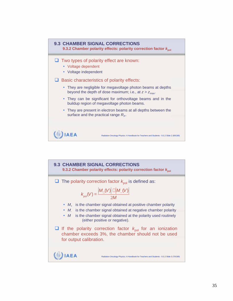
The polarity correction factor kpol is defined as:
• M+ is the chamber signal obtained at positive chamber polarity
• M- is the chamber signal obtained at negative chamber polarity
• M is the chamber signal obtained at the polarity used routinely
(either positive or negative).
If the polarity correction factor kpol for an ionization
chamber exceeds 3%, the chamber should not be used
for output calibration.
k
pol(V ) =
M+(V ) + M (V )
2M
36
IAEA Radiation Oncology Physics: A Handbook for Teachers and Students - 9.3.2 Slide 3 (71/189)
9.3 CHAMBER SIGNAL CORRECTIONS9.3.2 Chamber polarity effects: polarity correction factor kpol
Voltage-dependent polarity effects are caused by:
• Distortion of electric field by potential difference between the
guard and the collecting electrode.
• Space charge distortion of electric field lines defining the gas
sensitive volume.
• Difference in mobility of positive and negative ions causing
differences in space charge distribution around the central
electrode.
IAEA Radiation Oncology Physics: A Handbook for Teachers and Students - 9.3.2 Slide 4 (72/189)
9.3 CHAMBER SIGNAL CORRECTIONS9.3.2 Chamber polarity effects: polarity correction factor kpol
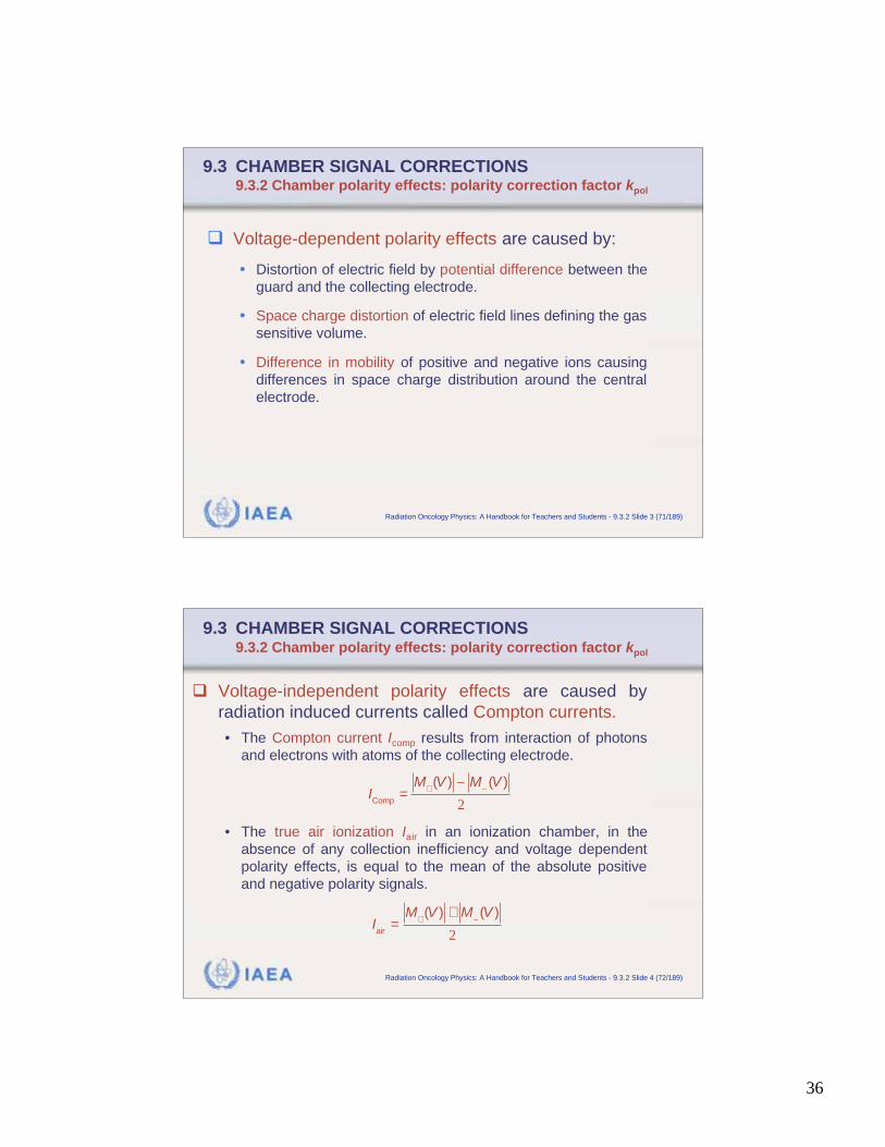
Voltage-independent polarity effects are caused by
radiation induced currents called Compton currents.
• The Compton current Icomp results from interaction of photons
and electrons with atoms of the collecting electrode.
• The true air ionization Iair in an ionization chamber, in the
absence of any collection inefficiency and voltage dependent
polarity effects, is equal to the mean of the absolute positive
and negative polarity signals.
Iair
=M
+(V ) + M (V )
2
IComp
=M
+(V ) M (V )
2
37
IAEA Radiation Oncology Physics: A Handbook for Teachers and Students - 9.3.2 Slide 5 (73/189)
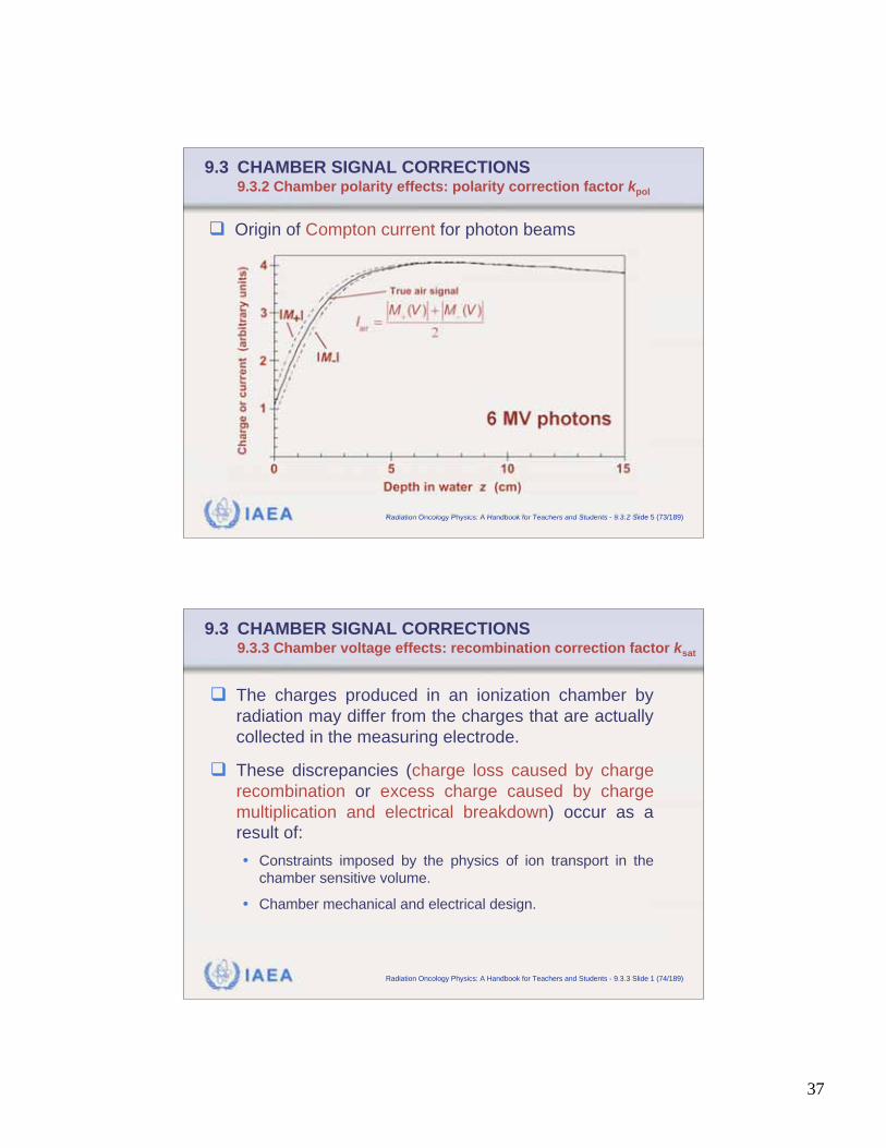
9.3 CHAMBER SIGNAL CORRECTIONS9.3.2 Chamber polarity effects: polarity correction factor kpol
Origin of Compton current for photon beams
IAEA Radiation Oncology Physics: A Handbook for Teachers and Students - 9.3.3 Slide 1 (74/189)
9.3 CHAMBER SIGNAL CORRECTIONS9.3.3 Chamber voltage effects: recombination correction factor ksat
The charges produced in an ionization chamber by
radiation may differ from the charges that are actually
collected in the measuring electrode.
These discrepancies (charge loss caused by charge
recombination or excess charge caused by charge
multiplication and electrical breakdown) occur as a
result of:
• Constraints imposed by the physics of ion transport in the
chamber sensitive volume.
• Chamber mechanical and electrical design.
38
IAEA Radiation Oncology Physics: A Handbook for Teachers and Students - 9.3.3 Slide 2 (75/189)
9.3 CHAMBER SIGNAL CORRECTIONS9.3.3 Chamber voltage effects: recombination correction factor ksat
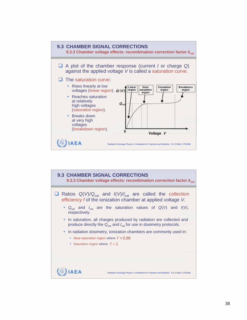
A plot of the chamber response (current I or charge Q)against the applied voltage V is called a saturation curve.
The saturation curve:
• Rises linearly at lowvoltages (linear region).
• Reaches saturationat relativelyhigh voltages(saturation region).
• Breaks downat very highvoltages(breakdown region).
IAEA Radiation Oncology Physics: A Handbook for Teachers and Students - 9.3.3 Slide 3 (76/189)
9.3 CHAMBER SIGNAL CORRECTIONS9.3.3 Chamber voltage effects: recombination correction factor ksat
Ratios Q(V)/Qsat and I(V)/Isat are called the collection
efficiency f of the ionization chamber at applied voltage V.
• Qsat and Isat are the saturation values of Q(V) and I(V),
respectively.
• In saturation, all charges produced by radiation are collected and
produce directly the Qsat and Isat for use in dosimetry protocols.
• In radiation dosimetry, ionization chambers are commonly used in:
• Near-saturation region where
• Saturation region where
f > 0.98
f 1
39
IAEA Radiation Oncology Physics: A Handbook for Teachers and Students - 9.3.3 Slide 4 (77/189)
9.3 CHAMBER SIGNAL CORRECTIONS9.3.3 Chamber voltage effects: recombination correction factor ksat
When the chamber is used below saturation, some of the
charges produced by radiation actually recombine and are
lost to the dosimetric signal.
The charge loss occurs through three different mechanisms:
• Initial recombination: opposite charges from same tracks collide and
recombine.
• General recombination: opposite charges from different tracks
collide and recombine. This is by far the predominant mode of
charge loss in an ionization chamber, and the other two are
generally ignored.
• Ionic diffusion loss: charges diffuse against the electric field.
IAEA Radiation Oncology Physics: A Handbook for Teachers and Students - 9.3.3 Slide 5 (78/189)
9.3 CHAMBER SIGNAL CORRECTIONS9.3.3 Chamber voltage effects: recombination correction factor ksat
In studies of ionic recombination losses, ionizing radiation
is classified into three categories:
• Continuous radiation (e.g., cobalt-60 gamma ray beams and ortho-
voltage x rays)
• Pulsed beams (e.g., non-scanned linac x-ray beams and electrons)
• Scanned pulsed beams (e.g., scanned linac beams)
The ionic recombination correction factor ksat accounts for
loss of ions in the chamber sensitive volume due to initial
recombination, general recombination, and diffusion loss.
• ksat is labelled Pion in the AAPM TG 21 and TG 51 protocols.
• ksat equals 1/f in the ionic recombination theory.
40
IAEA Radiation Oncology Physics: A Handbook for Teachers and Students - 9.3.3 Slide 6 (79/189)
9.3 CHAMBER SIGNAL CORRECTIONS9.3.3 Chamber voltage effects: recombination correction factor ksat
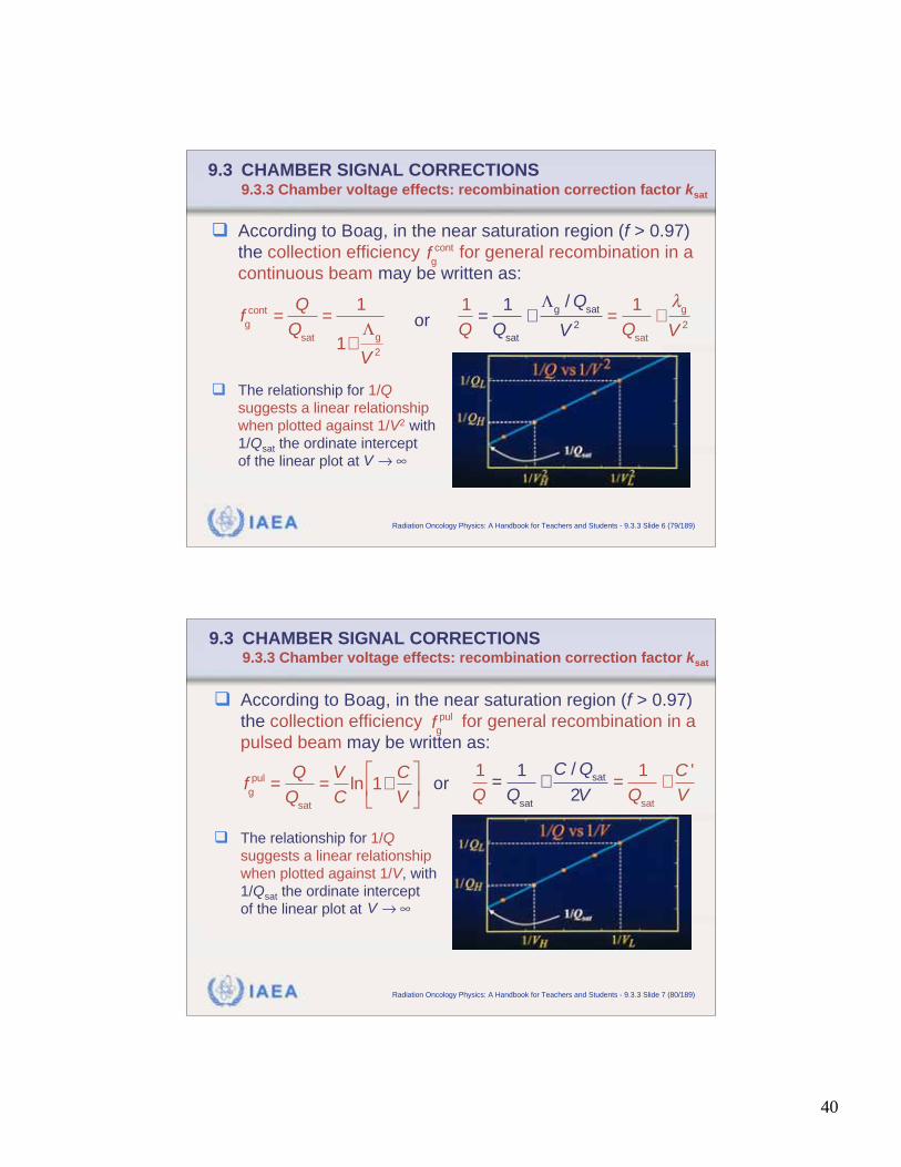
According to Boag, in the near saturation region (f > 0.97)
the collection efficiency for general recombination in a
continuous beam may be written as:
The relationship for 1/Q
suggests a linear relationship
when plotted against 1/V2 with
1/Qsat the ordinate intercept
of the linear plot at
fg
cont
fg
cont=
Q
Qsat
=1
1+g
V2
1
Q=
1
Qsat
+g
/ Qsat
V2
=1
Qsat
+g
V2or
V
IAEA Radiation Oncology Physics: A Handbook for Teachers and Students - 9.3.3 Slide 7 (80/189)
9.3 CHAMBER SIGNAL CORRECTIONS9.3.3 Chamber voltage effects: recombination correction factor ksat
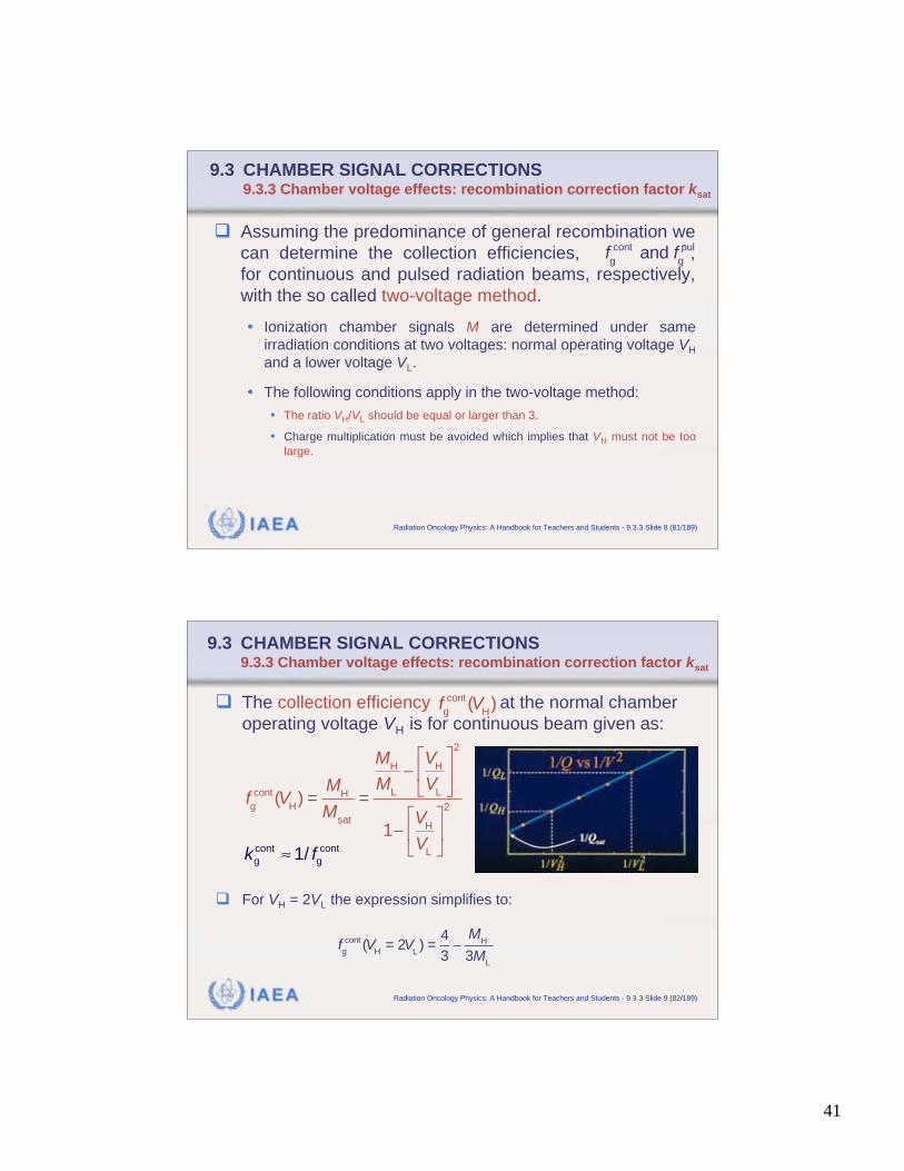
According to Boag, in the near saturation region (f > 0.97)
the collection efficiency for general recombination in a
pulsed beam may be written as:
The relationship for 1/Q
suggests a linear relationship
when plotted against 1/V, with
1/Qsat the ordinate intercept
of the linear plot at
fg
pul
fg
pul=
Q
Qsat
=V
Cln 1+
C
V
1
Q=
1
Qsat
+C / Q
sat
2V=
1
Qsat
+C '
Vor
V
41
IAEA Radiation Oncology Physics: A Handbook for Teachers and Students - 9.3.3 Slide 8 (81/189)
9.3 CHAMBER SIGNAL CORRECTIONS9.3.3 Chamber voltage effects: recombination correction factor ksat
Assuming the predominance of general recombination we
can determine the collection efficiencies, ,
for continuous and pulsed radiation beams, respectively,
with the so called two-voltage method.
• Ionization chamber signals M are determined under same
irradiation conditions at two voltages: normal operating voltage VH
and a lower voltage VL.
• The following conditions apply in the two-voltage method:
• The ratio VH/VL should be equal or larger than 3.
• Charge multiplication must be avoided which implies that VH must not be too
large.
fg
cont and fg
pul
IAEA Radiation Oncology Physics: A Handbook for Teachers and Students - 9.3.3 Slide 9 (82/189)
9.3 CHAMBER SIGNAL CORRECTIONS9.3.3 Chamber voltage effects: recombination correction factor ksat
The collection efficiency at the normal chamber
operating voltage VH is for continuous beam given as:
For VH = 2VL the expression simplifies to:
fg
cont (VH)
fg
cont (VH) =
MH
Msat
=
MH
ML
VH
VL
2
1V
H
VL
2
fg
cont (VH
= 2VL) =
4
3
MH
3ML
cont cont
g g1/k f
42
IAEA Radiation Oncology Physics: A Handbook for Teachers and Students - 9.3.3 Slide 10 (83/189)
9.3 CHAMBER SIGNAL CORRECTIONS9.3.3 Chamber voltage effects: recombination correction factor ksat
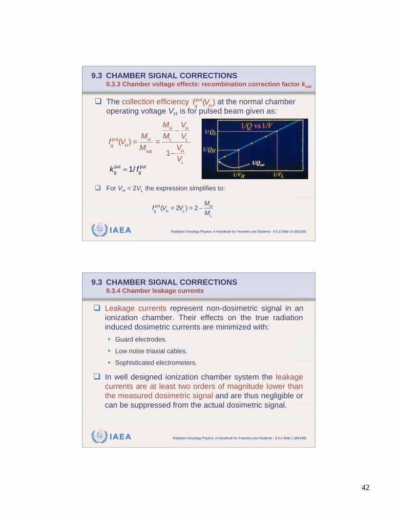
The collection efficiency at the normal chamber
operating voltage VH is for pulsed beam given as:
For VH = 2VL the expression simplifies to:
fg
pul(VH)
fg
pul(VH) =
MH
Msat
=
MH
ML
VH
VL
1V
H
VL
fg
pul(VH
= 2VL) = 2
MH
ML
pul pul
g g1/k f
IAEA Radiation Oncology Physics: A Handbook for Teachers and Students - 9.3.4 Slide 1 (84/189)
9.3 CHAMBER SIGNAL CORRECTIONS9.3.4 Chamber leakage currents
Leakage currents represent non-dosimetric signal in an
ionization chamber. Their effects on the true radiation
induced dosimetric currents are minimized with:
• Guard electrodes.
• Low noise triaxial cables.
• Sophisticated electrometers.
In well designed ionization chamber system the leakage
currents are at least two orders of magnitude lower than
the measured dosimetric signal and are thus negligible or
can be suppressed from the actual dosimetric signal.

43
IAEA Radiation Oncology Physics: A Handbook for Teachers and Students - 9.3.4 Slide 2 (85/189)
9.3 CHAMBER SIGNAL CORRECTIONS9.3.4 Chamber leakage currents
Leakage currents fall into three categories:
• Intrinsic (dark) leakage currents result from surface and volume
leakage currents flowing between the polarizing and measuring
electrodes of the ionization chamber.
• Radiation induced leakage currents occur as a consequence of
the irradiation of insulators and chamber parts, cables and
electronics of the measuring equipment.
• Mechanical stress induced and friction induced spurious cable
currents result from bending and twisting of cables.
IAEA Radiation Oncology Physics: A Handbook for Teachers and Students - 9.3.5 Slide 1 (86/189)
9.3 CHAMBER SIGNAL CORRECTIONS9.3.5 Chamber stem effects
Irradiation of ionization chamber stem results in a
specific type of leakage current called the stem effect.
Two mechanisms of stem effect have been identified:
• Stem scatter arises from the effect of scattered radiation in the
stem that reaches the chamber volume.
• Stem leakage arises as a consequence of a direct irradiation
of this chamber volume as well as of the insulators and cables
of the chamber.
44
IAEA Radiation Oncology Physics: A Handbook for Teachers and Students - 9.4 Slide 1 (87/189)
9.4 DETERMINATION OF ABSORBED DOSE USING
CALIBRATED IONIZATION CHAMBERS
For practical reasons, outputs of clinical photon and
electron beams are usually measured with ionization
chambers that have calibration coefficients traceable
to a standards laboratory and are thus used as relative
dosimeters.
These chambers are then used in radiation dosimetry
in conjunction with a suitable dosimetry protocol (code
of practice).
IAEA Radiation Oncology Physics: A Handbook for Teachers and Students - 9.4 Slide 2 (88/189)
9.4 DETERMINATION OF ABSORBED DOSE USING
CALIBRATED IONIZATION CHAMBERS
A dosimetry protocol provides the formalism and the data
to relate a calibration of a chamber at a standards labo-
ratory to the measurement of absorbed dose to water
under reference conditions in the clinical beam.
Two types of dosimetry protocol are currently in use:
• Protocols based on air kerma in air calibration coefficients.
• Protocols based on dose to water calibration coefficients.
Conceptually, both types of protocol are similar and
define the steps to be used in the process of determining
absorbed dose from a signal measured by an ionization
chamber.
45
IAEA Radiation Oncology Physics: A Handbook for Teachers and Students - 9.4 Slide 3 (89/189)
9.4 DETERMINATION OF ABSORBED DOSE USING
CALIBRATED IONIZATION CHAMBERS
The first step in the use of a dosimetry protocol involves
the determination of the chamber signal MQ at beam
quality Q through correction of the measured chamber
charge or current for influence quantities.
Radiation dosimetry formalisms are based upon:
• Cobalt-60 calibration coefficients for megavoltage photon and
electron beams.
• Calibration coefficients obtained for the particular beam quality
used for superficial and orthovoltage x-ray beams.
IAEA Radiation Oncology Physics: A Handbook for Teachers and Students - 9.4.1 Slide 1 (90/189)
9.4 USE OF CALIBRATED IONIZATION CHAMBERS9.4.1 Air kerma based protocols
Air kerma based protocols use the air kerma in air cali-
bration coefficient NK,Co obtained for a local reference
ionization chamber in a cobalt-60 beam at a standards
laboratory.
Two steps are involved in air kerma based protocols for
calibration of megavoltage photon and electron beams.
• The cavity air calibration coefficient ND,air is determined from the
air kerma in air calibration coefficient NK,Co.
• Absorbed dose to water is determined using the Bragg-Gray
relationship in conjunction with the chamber signal MQ and the
cavity air calibration coefficient ND,air.
46
IAEA Radiation Oncology Physics: A Handbook for Teachers and Students - 9.4.1 Slide 2 (91/189)
9.4 USE OF CALIBRATED IONIZATION CHAMBERS9.4.1 Air kerma based protocols
Calibration in a cobalt-60 beam at standards laboratory:
Absorbed dose to air in the cavity Dair,Co is determined from
the total air kerma in air (Kair)air as follows:
• is the radiative fraction, i.e., the fraction of the total transferred
energy expended in radiation interactions on slowing down of
the secondary electrons in air.
• km corrects for the non-air equivalence of the chamber wall and
buildup cap needed for an air kerma in air measurement.
• katt corrects for attenuation and scatter in the chamber wall.
• kcel corrects for non-air equivalence of chamber central electrode.
D
air,Co= (K
air)
air (1 g) k
m k
att k
cel
g
IAEA Radiation Oncology Physics: A Handbook for Teachers and Students - 9.4.1 Slide 3 (92/189)
9.4 USE OF CALIBRATED IONIZATION CHAMBERS9.4.1 Air kerma based protocols
Calibration in a cobalt-60 beam at standards laboratory:
Cavity air calibration coefficient ND,air is defined as:
• Dair,Co is the absorbed dose to airin the chamber cavity.
• MCo is the chamber signal corrected for influence quantities.
Air kerma in air calibration coefficient NK,Co is:
ND,air
=D
air,Co
MCo
NK,Co
=(K
air)
air
MCo
47
IAEA Radiation Oncology Physics: A Handbook for Teachers and Students - 9.4.1 Slide 4 (93/189)
9.4 USE OF CALIBRATED IONIZATION CHAMBERS9.4.1 Air kerma based protocols
Calibration in a cobalt-60 beam at standards laboratory:
Absorbed dose to air in the cavity was given as:
Cavity air calibration coefficient ND,air is now:
N
D,air= N
K,Co (1 g) k
m k
att k
cel
D
air,Co= (K
air)
air (1 g) k
m k
att k
cel
= =air,Co air air
D,air m att cel m att celK,Co
Co Co
( )(1 ) (1 )
D KN g k k k N g k k k
M M
IAEA Radiation Oncology Physics: A Handbook for Teachers and Students - 9.4.1 Slide 5 (94/189)
9.4 USE OF CALIBRATED IONIZATION CHAMBERS9.4.1 Air kerma based protocols
Calibration in a cobalt-60 beam at standards laboratory:
Cavity air calibration coefficient ND,air is also directly
related to the effective volume Veff of the chamber by:
ND,air is a characteristic of the dosimetric device:
• It depends only on the effective mass of the air in the chamber.
• Does not depend on radiation quality as long as (Wair/e) is
independent of the radiation quality.
ND,air
=D
air
MCo
=1
mair
W air
e=
1
airV
eff
W air
e
48
IAEA Radiation Oncology Physics: A Handbook for Teachers and Students - 9.4.1 Slide 6 (95/189)
9.4 USE OF CALIBRATED IONIZATION CHAMBERS9.4.1 Air kerma based protocols
The absorbed dose to air Dair,Q in the air cavity irradiated
by a megavoltage beam of quality Q can be converted
into absorbed dose to medium (e.g., water) Dw,Q by
making use of the Bragg-Gray (B-G) cavity relationship.
Bragg-Gray (B-G) cavity theory provides a relationship
between dose in a dosimeter (cavity air) and dose in the
medium (water) containing the dosimeter (cavity).
• Cavity must be small so as not to perturb the fluence of charged
particles in the medium.
• Absorbed dose in the cavity must be deposited solely by charged
particles crossing the cavity.
IAEA Radiation Oncology Physics: A Handbook for Teachers and Students - 9.4.1 Slide 7 (96/189)
9.4 USE OF CALIBRATED IONIZATION CHAMBERS9.4.1 Air kerma based protocols
Under these special conditions, according to the B-G
cavity theory, the dose to the medium Dmed is related to
the dose to the cavity Dcav as:
• is the ratio of the average unrestricted mass
collision stopping powers medium to cavity.
The Spencer-Attix (S-A) cavity theory is more general
and accounts for the creation of secondary (delta)
electrons. The dose to medium is given as:
• is the ratio of the average restricted mass collision
stopping powers medium to cavity.
Dmed= D
cav (s
med.cav)
(s
med.cav)
D
med= D
cav (S / )
med,cav
(S / )
med,cav
49
IAEA Radiation Oncology Physics: A Handbook for Teachers and Students - 9.4.1 Slide 8 (97/189)
9.4 USE OF CALIBRATED IONIZATION CHAMBERS9.4.1 Air kerma based protocols
With a known value of the cavity air calibration coefficient
ND,air for a specific chamber, the chamber signal corrected
for influence quantities MQ at a point in phantom allows
determination of absorbed dose to water Dw,Q:
• is the ratio of average restricted collision stopping powers
of water to air for a radiation beam of quality Q.
• pQ is a perturbation correction factor accounting for
perturbations caused by the ionization chamber inserted
into the medium (water).
D
w,Q= D
air,Q (s
w,air)
Q p
Q= M
Q N
D,air (s
w,air)
Q p
Q
w,air Q( )s
IAEA Radiation Oncology Physics: A Handbook for Teachers and Students - 9.4.2 Slide 1 (98/189)
9.4 USE OF CALIBRATED IONIZATION CHAMBERS9.4.2 Absorbed dose to water based protocols
Calibration in a cobalt-60 beam at standards laboratory:
Recent developments have provided support for a
change in the quantity used to calibrate ionization
chambers and provide calibration coefficients in
terms of absorbed dose to water at beam quality Qo .
At standards laboratory , absorbed dose to water at
the reference depth zref in water for a reference beam
Qo (usually cobalt-60) is known and used to determine
the water dose calibration coefficient .
D
w,Qo
N
D,w,Qo
N
D,w,Qo
50
IAEA Radiation Oncology Physics: A Handbook for Teachers and Students - 9.4.2 Slide 2 (99/189)
9.4 USE OF CALIBRATED IONIZATION CHAMBERS9.4.2 Absorbed dose to water based protocols
Calibration in a quality Qo beam (usually cobalt-60 gamma
rays) at the standards laboratory:
Absorbed dose to water at the reference depth
zref in water for a reference beam Qo is:
• is the chamber reading under the reference conditions
used in the standards laboratory and corrected for
influence quantities.
• is the water dose calibration coefficient for chamber at
beam quality Qo (usually cobalt-60).
D
w,Qo
N
D,w,Qo
D
w,Qo
= MQ
o
ND,w,Q
o
M
Qo
IAEA Radiation Oncology Physics: A Handbook for Teachers and Students - 9.4.2 Slide 3 (100/189)
9.4 USE OF CALIBRATED IONIZATION CHAMBERS9.4.2 Absorbed dose to water based protocols
When a chamber is used in a beam quality Q that differsfrom the quality Qo used in the chamber calibration at thestandards laboratory, the absorbed dose to water is:
• is the chamber reading in beam of quality Q and correctedfor influence quantities to the reference conditions used inthe standards laboratory.
• is the water dose calibration coefficient provided by thestandards laboratory for reference beam quality Qo.
• is a factor correcting for differences between reference beam quality Qo and the actual user quality Q.
N
D,w,Qo
D
w,Q= M
Q N
D,w,Qo
kQ.Q
o
QM
k
Q,Qo
51
IAEA Radiation Oncology Physics: A Handbook for Teachers and Students - 9.4.2 Slide 4 (101/189)
9.4 USE OF CALIBRATED IONIZATION CHAMBERS9.4.2 Absorbed dose to water based protocols
Beam quality correction factor is defined as the
ratio, at beam qualities Q and Qo, of the calibration
coefficients in terms of absorbed dose to water of the
ionization chamber:
Currently, the common reference quality Qo used for
the calibration of ionization chambers is the cobalt-60
gamma radiation and the symbol kQ is normally used to
designate the beam quality correction factor:
k
Q,Qo
kQ,Q
o
=N
D,w,Q
ND,w,Q
o
k
Q,Qo
= kQ,Co
= kQ
IAEA Radiation Oncology Physics: A Handbook for Teachers and Students - 9.4.2 Slide 5 (102/189)
9.4 USE OF CALIBRATED IONIZATION CHAMBERS9.4.2 Absorbed dose to water based protocols
The beam quality correction factor is difficult to
measure, so it is usually calculated theoretically using:
• The air kerma in air formalism:
or
• The dose to water formalism:
The beam quality correction factor can be written as:
k
Q,Qo
kQ,Q
o
=N
D,w,Q
ND,w,Q
o
=(s
w,air)
Q
(sw,air
)Q
o
pQ
pQ
o
D
w,Q= M
Q N
D,w,Qo
kQ.Q
o
= D,air w,airw,Q Q Q Q ( ) D M N s p
k
Q,Qo
52
IAEA Radiation Oncology Physics: A Handbook for Teachers and Students - 9.4.2 Slide 6 (103/189)
9.4 USE OF CALIBRATED IONIZATION CHAMBERS9.4.2 Absorbed dose to water based protocols
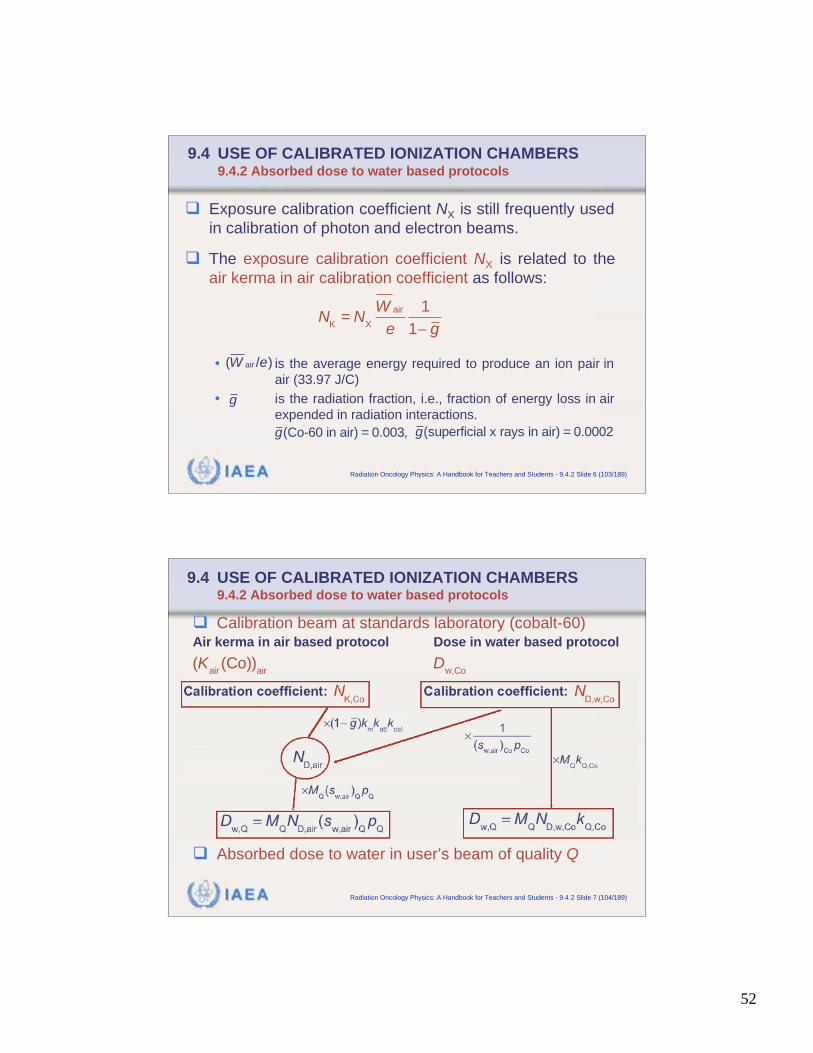
Exposure calibration coefficient NX is still frequently used
in calibration of photon and electron beams.
The exposure calibration coefficient NX is related to the
air kerma in air calibration coefficient as follows:
• is the average energy required to produce an ion pair in
air (33.97 J/C)
• is the radiation fraction, i.e., fraction of energy loss in air
expended in radiation interactions.
N
K= N
X
W air
e
1
1 g
air( / )W e
g
g(Co-60 in air) = 0.003, g(superficial x rays in air) = 0.0002
IAEA Radiation Oncology Physics: A Handbook for Teachers and Students - 9.4.2 Slide 7 (104/189)
9.4 USE OF CALIBRATED IONIZATION CHAMBERS9.4.2 Absorbed dose to water based protocols
Calibration beam at standards laboratory (cobalt-60)Air kerma in air based protocol Dose in water based protocol
Absorbed dose to water in user’s beam of quality Q
(Kair(Co))
air D
w,Co
53
IAEA Radiation Oncology Physics: A Handbook for Teachers and Students - 9.4.2 Slide 8 (105/189)
9.4 USE OF CALIBRATED IONIZATION CHAMBERS9.4.2 Absorbed dose to water based protocols
The air kerma in air based formalism and the absorbed
dose to water based formalism for the determination of
absorbed dose to water in reference conditions include:
• Stopping power ratios (essentially independent of the detector).
• Correction factors for perturbation effects that are detector
dependent and may include mass-energy absorption coefficient
ratios.
Ideally, the formalism in terms of absorbed dose to water
is based on experimentally determined quantities; how-
ever, the beam quality factors are currently deter-
mined theoretically. k
Q,Qo
IAEA Radiation Oncology Physics: A Handbook for Teachers and Students - 9.5 Slide 1 (106/189)
9.5 STOPPING POWER RATIOS
The determination of absorbed dose in a medium using
an ionization chamber is based on the B-G principle:
• Relating the absorbed dose at a point in the medium (water) Dw
• To the mean absorbed dose in the detector (air) .
• Through a proportionality factor that classically has been iden-
tified as the ratio of mass collision stopping powers water to air.
The key Bragg-Gray assumption is that electron fluence
present in detector is identical to that in the undisturbed
medium at the point of interest in the water phantom.
airD
54
IAEA Radiation Oncology Physics: A Handbook for Teachers and Students - 9.5 Slide 2 (107/189)
9.5 STOPPING POWER RATIOS
The gas filled ionization chamber in a megavoltage
photon or electron beam behaves to a good approx-
imation as a Bragg-Gray detector.
• Any deviations from the Bragg-Gray behaviour are accounted
for by perturbation factors.
• Fulfillment of the two Bragg-Gray conditions depends on the
cavity size compared to the range of electrons in the cavity
medium.
IAEA Radiation Oncology Physics: A Handbook for Teachers and Students - 9.5.1 Slide 1 (108/189)
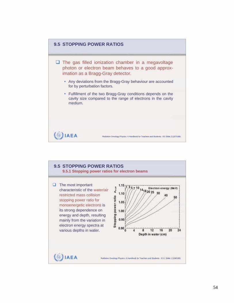
9.5 STOPPING POWER RATIOS9.5.1 Stopping power ratios for electron beams
The most important
characteristic of the water/air
restricted mass collision
stopping power ratio for
monoenergetic electrons is
its strong dependence on
energy and depth, resulting
mainly from the variation in
electron energy spectra at
various depths in water.
55
IAEA Radiation Oncology Physics: A Handbook for Teachers and Students - 9.5.2 Slide 1 (109/189)
9.5 STOPPING POWER RATIOS9.5.2 Stopping power ratios for photon beams
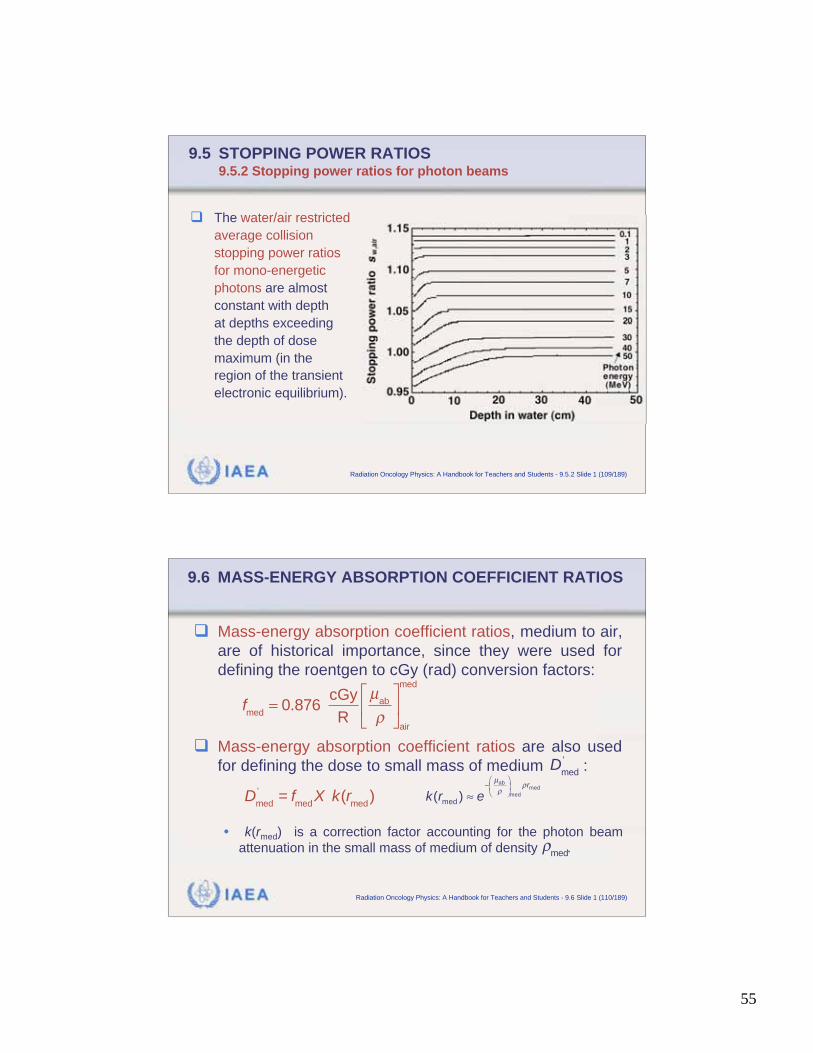
The water/air restricted
average collision
stopping power ratios
for mono-energetic
photons are almost
constant with depth
at depths exceeding
the depth of dose
maximum (in the
region of the transient
electronic equilibrium).
IAEA Radiation Oncology Physics: A Handbook for Teachers and Students - 9.6 Slide 1 (110/189)
9.6 MASS-ENERGY ABSORPTION COEFFICIENT RATIOS
Mass-energy absorption coefficient ratios, medium to air,
are of historical importance, since they were used for
defining the roentgen to cGy (rad) conversion factors:
Mass-energy absorption coefficient ratios are also used
for defining the dose to small mass of medium :
• k(rmed) is a correction factor accounting for the photon beam
attenuation in the small mass of medium of density .
fmed
= 0.876 cGy
R
μab
air
med
D
med
'
Dmed
'= f
medX k(r
med)
abmed
med
med( )r
k r e
μ
med
56
IAEA Radiation Oncology Physics: A Handbook for Teachers and Students - 9.6 Slide 2 (111/189)
9.6 MASS-ENERGY ABSORPTION COEFFICIENT RATIOS
The role of spectrum averaged mass-energy absorption
coefficient ratios in modern dosimetry protocols is
mainly restricted to their use in calculating perturbation
and other correction factors for ionization chambers in
cobalt-60 and high energy photon beams.
In general, mass-energy absorption coefficient ratios are
associated with the fraction of energy deposited within a
detector due to electrons generated by photon inter-
actions in the detector material.
IAEA Radiation Oncology Physics: A Handbook for Teachers and Students - 9.7 Slide 1 (112/189)
9.7 PERTURBATION CORRECTION FACTORS
For a detector to behave as a Bragg-Gray cavity, the
electron fluence in the sensitive medium of the detector
must be identical to that at a specified point in a uniform
medium.
The only possible true Bragg-Gray detector would be an
exceedingly small air bubble; all protocols for absolute
dose determination are based on air filled ionization
chambers.
57
IAEA Radiation Oncology Physics: A Handbook for Teachers and Students - 9.7 Slide 2 (113/189)
9.7 PERTURBATION CORRECTION FACTORS
For megavoltage photon radiation the Bragg-Gray
conditions are adequately fulfilled for air cavity sizes
encountered in practical ionization chambers with:
• Volumes of 0.01 cm3 to 0.6 cm3 in cylindrical chambers.
• Electrode separations of the order of 1 mm in parallel-plate
chambers.
In cylindrical ionization chambers neither the wall nor
the central electrode are medium (water) equivalent,
and this introduces deviations from perfect Bragg-
Gray behaviour.
IAEA Radiation Oncology Physics: A Handbook for Teachers and Students - 9.7 Slide 3 (114/189)
9.7 PERTURBATION CORRECTION FACTORS
Deviations from Bragg-Gray behaviour are generally
dealt by introducing appropriate correction (perturbation)
factors into the expression for the absorbed dose:
Perturbation factor pQ is often written as a product of four
perturbation factors, each one accounting for a different
effect, valid for beam quality Q and assumed to be
independent of the others:
D
w,Q= M
Q N
D,air (s
w,air)
Q p
Q
pQ= (p
dis p
wall p
cel p
cav)
Q
58
IAEA Radiation Oncology Physics: A Handbook for Teachers and Students - 9.7 Slide 4 (115/189)
9.7 PERTURBATION CORRECTION FACTORS
The perturbation correction factor pQ corrects for 4 effectsthat cause deviations from Bragg-Gray behaviour:
• pdis accounts for the effect of replacing a volume of water with the chamber air cavity in cylindrical chambers.
• pwall accounts for the non-water equivalence of the chamber walland any waterproofing material.
• pcel accounts for the effect of the central electrode during in-phantom measurements.
• pdis accounts for the effects of the air cavity on the in-scatteringof electrons making the electrons fluence different from thatin water in absence of the cavity.
pQ= (p
dis p
wall p
cel p
cav)
Q
IAEA Radiation Oncology Physics: A Handbook for Teachers and Students - 9.7.1 Slide 1 (116/189)
9.7 PERTURBATION CORRECTION FACTORS9.7.1 Displacement perturbation factor pdis
Ionization chamber placed into a phantom will displace
a certain volume of the phantom medium and replace it
with wall (possibly medium equivalent) and air.
The chamber reading will be affected by the “missing”
medium in two ways:
• Reduced attenuation
• Reduced scatter.
Net result of reduced attenuation and reduced scatter is
an increase in chamber signal. The increase in the
signal is corrected for by the displacement perturbation
factor pdis which is less than unity.
59
IAEA Radiation Oncology Physics: A Handbook for Teachers and Students - 9.7.1 Slide 2 (117/189)
9.7 PERTURBATION CORRECTION FACTORS9.7.1 Displacement perturbation factor pdis
Displacement perturbation factor pdis depends upon:
• Radiation quality Q.
• Physical dimensions of the air cavity in the direction of the beam.
• Depth of measurement.
In photon beams
• pdis is essentially constant for depths beyond zmax.
• pdis varies in a complicated fashion with depth in the buildup region.
For a cobalt beam pdis = 0.988 for a Farmer chamber with
internal radius of 3 mm.
IAEA Radiation Oncology Physics: A Handbook for Teachers and Students - 9.7.1 Slide 3 (118/189)
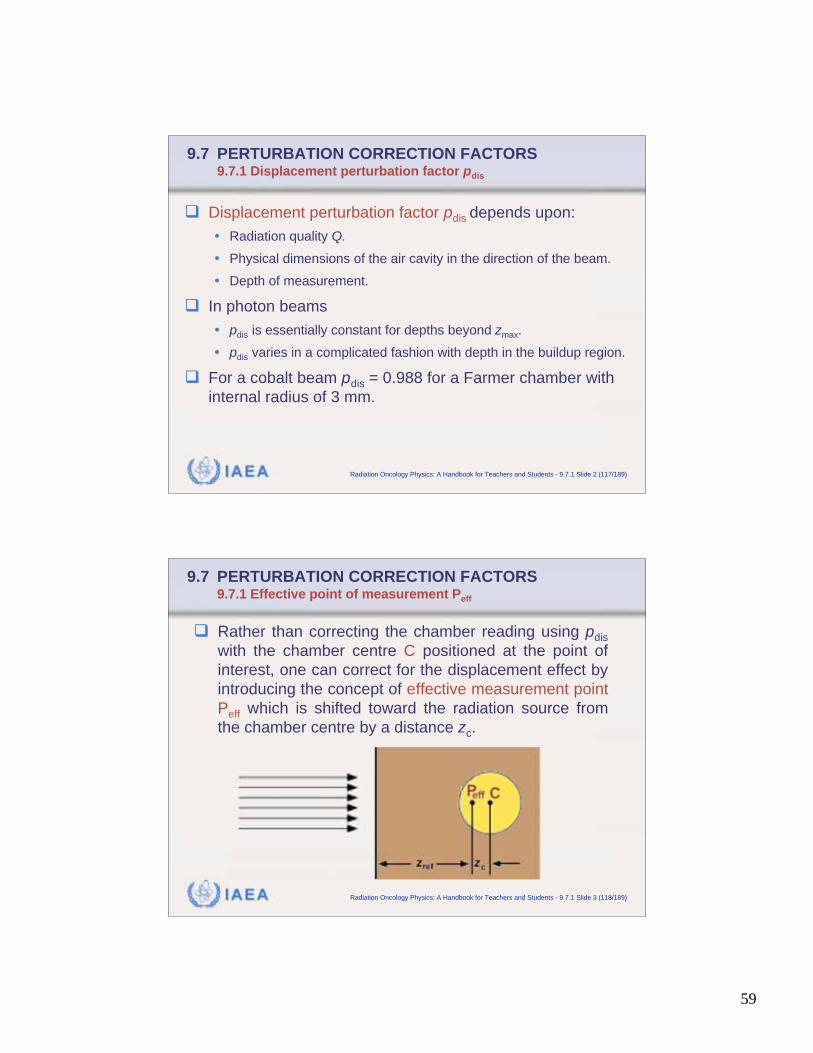
9.7 PERTURBATION CORRECTION FACTORS9.7.1 Effective point of measurement Peff
Rather than correcting the chamber reading using pdis
with the chamber centre C positioned at the point of
interest, one can correct for the displacement effect by
introducing the concept of effective measurement point
Peff which is shifted toward the radiation source from
the chamber centre by a distance zc.
60
IAEA Radiation Oncology Physics: A Handbook for Teachers and Students - 9.7.1 Slide 4 (119/189)
9.7 PERTURBATION CORRECTION FACTORS9.7.1 Effective point of measurement Peff
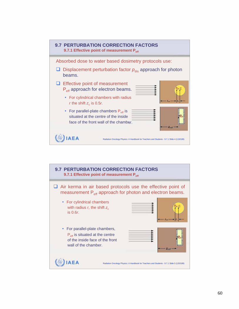
Absorbed dose to water based dosimetry protocols use:
Displacement perturbation factor pdis approach for photon
beams.
Effective point of measurement
Peff approach for electron beams.
• For cylindrical chambers with radius
r the shift zc is 0.5r.
• For parallel-plate chambers Peff is
situated at the centre of the inside
face of the front wall of the chamber.
IAEA Radiation Oncology Physics: A Handbook for Teachers and Students - 9.7.1 Slide 5 (120/189)
9.7 PERTURBATION CORRECTION FACTORS9.7.1 Effective point of measurement Peff
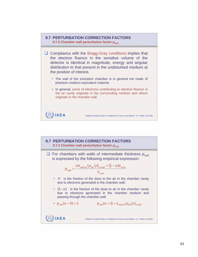
Air kerma in air based protocols use the effective point of
measurement Peff approach for photon and electron beams.
• For cylindrical chambers
with radius r, the shift zc
is 0.6r.
• For parallel-plate chambers,
Peff is situated at the centre
of the inside face of the front
wall of the chamber.
61
IAEA Radiation Oncology Physics: A Handbook for Teachers and Students - 9.7.2 Slide 1 (121/189)
9.7 PERTURBATION CORRECTION FACTORS9.7.2 Chamber wall perturbation factor pwall
Compliance with the Bragg-Gray conditions implies that
the electron fluence in the sensitive volume of the
detector is identical in magnitude, energy and angular
distribution to that present in the undisturbed medium at
the position of interest.
• The wall of the ionization chamber is in general not made of
phantom medium-equivalent material.
• In general, some of electrons contributing to electron fluence in
the air cavity originate in the surrounding medium and others
originate in the chamber wall.
IAEA Radiation Oncology Physics: A Handbook for Teachers and Students - 9.7.2 Slide 2 (122/189)
9.7 PERTURBATION CORRECTION FACTORS9.7.2 Chamber wall perturbation factor pwall
For chambers with walls of intermediate thickness pwall
is expressed by the following empirical expression:
• is the fraction of the dose to the air in the chamber cavity
due to electrons generated in the chamber wall.
• is the fraction of the dose to air in the chamber cavity
due to electrons generated in the chamber medium and
passing through the chamber wall.
•
pwall
=s
wall,air(μ
ab/ )
w,wall+ (1 )s
w,air
sw,air
μ= = = =wall wall wall,air ab w,wall( 0) 1 ( 1) ( / )p p s
(1 )
62
IAEA Radiation Oncology Physics: A Handbook for Teachers and Students - 9.7.2 Slide 3 (123/189)
9.7 PERTURBATION CORRECTION FACTORS9.7.2 Chamber wall perturbation factor pwall
When a waterproofing sleeve is used with an ionization
chamber in a water phantom, pwall is expressed as:
• is the fraction of the dose to the air in the chamber cavity due
to electrons generated in the chamber wall.
• is the fraction of the dose to the air in the chamber cavity due
to electrons generated in the sleeve.
• is the fraction of the dose to air in the chamber cavity
due to electrons generated in the chamber medium and passing
through the chamber wall and the sleeve.
pwall
=s
wall,air(μ
ab/ )
w,wall+ s
sleeve,air(μ
ab/ )
w,sleeve+ (1 )s
w,air
sw,air
(1 )
IAEA Radiation Oncology Physics: A Handbook for Teachers and Students - 9.7.2 Slide 4 (124/189)
9.7 PERTURBATION CORRECTION FACTORS9.7.2 Chamber wall perturbation factor pwall
For cobalt-60 beams the two parameters are
estimated from known chamber wall thickness twall (in
g/cm2) and sleeve thickness tsleeve (in g/cm2) using:
For high energy megavoltage x-ray beams, the
fractional ionizations are derived from data
given in the IAEA TRS 398 protocol.
For megavoltage electron beams, the effect of the
chamber wall is assumed negligible.
and
= 1 e11.88t
wall = e11.88t
wall e11.88(t
wall+t
sleeve)
and
63
IAEA Radiation Oncology Physics: A Handbook for Teachers and Students - 9.7.3 Slide 1 (125/189)
9.7 PERTURBATION CORRECTION FACTORS9.7.3 Central electrode perturbation factor pcel
Cylindrical ionization chambers have a central electrode,
usually made of aluminum or graphite.
The central electrode produces an increase in the chamber
signal compared with the signal that would be obtained in a
Bragg-Gray air bubble. Central electrode correction factor
pcel is introduced to correct for this effect.
• In photon beams a graphite electrode produces essentially no
effect; the effect of a 1 mm diameter aluminum electrode decreases
with beam energy from 1.008 to 1.004.
• In electron beams the effect is negligible for graphite; the effect is
smaller than 0.2% for 1 mm diameter aluminum electrode.
IAEA Radiation Oncology Physics: A Handbook for Teachers and Students - 9.7.4 Slide 1 (126/189)
9.7 PERTURBATION CORRECTION FACTORS9.7.4 Cavity or fluence perturbation factor pcav
An ionization chamber introduces a low density hetero-
geneity (gas cavity) into a medium and this causes a per-
turbation of the electron fluence.
According to Harder, in unperturbed medium the angular distribution
of electrons broadens in the cavity with depth; a low density cavity
will scatter out fewer electrons than are scattered in. This results in
an increase in the electron fluence
toward the downstream end of
the cavity in comparison with the
fluence in a uniform medium at
same depth.
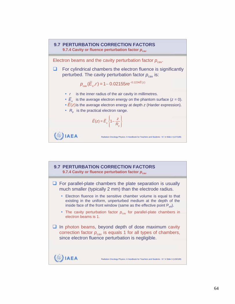
64
IAEA Radiation Oncology Physics: A Handbook for Teachers and Students - 9.7.4 Slide 2 (127/189)
9.7 PERTURBATION CORRECTION FACTORS9.7.4 Cavity or fluence perturbation factor pcav
Electron beams and the cavity perturbation factor pcav.
For cylindrical chambers the electron fluence is significantly
perturbed. The cavity perturbation factor pcav is:
• r is the inner radius of the air cavity in millimetres.
• is the average electron energy on the phantom surface (z = 0).
• is the average electron energy at depth z (Harder expression).
• Rp is the practical electron range.
pcav(E
o,r ) = 1 0.02155re 0.1224E (z)
oE
( )E z
E(z) = Eo
1z
Rp
IAEA Radiation Oncology Physics: A Handbook for Teachers and Students - 9.7.4 Slide 3 (128/189)
9.7 PERTURBATION CORRECTION FACTORS9.7.4 Cavity or fluence perturbation factor pcav
For parallel-plate chambers the plate separation is usually
much smaller (typically 2 mm) than the electrode radius.
• Electron fluence in the sensitive chamber volume is equal to that
existing in the uniform, unperturbed medium at the depth of the
inside face of the front window (same as the effective point Peff).
• The cavity perturbation factor pcav for parallel-plate chambers in
electron beams is 1.
In photon beams, beyond depth of dose maximum cavity
correction factor pcav is equals 1 for all types of chambers,
since electron fluence perturbation is negligible.
65
IAEA Radiation Oncology Physics: A Handbook for Teachers and Students - 9.8 Slide 1 (129/189)
9.8 BEAM QUALITY SPECIFICATION
To obtain the absorbed dose to water at a reference point
in water the signal (current or charge) that is produced by
an ionization chamber and measured by an electrometer
must be multiplied by various factors correcting for:
• Influence quantities (air temperature, pressure, humidity, polarity
effects, collections efficiency, stem effects, etc.).
• Various dosimetric physical quantities related to deviations from
Bragg-Gray conditions.
Some of these quantities depend upon photon or electron
beam energy, thus the beam quality must be specified for
these calculations.
IAEA Radiation Oncology Physics: A Handbook for Teachers and Students - 9.8 Slide 2 (130/189)
9.8 BEAM QUALITY SPECIFICATION
The most straightforward means to characterize the
quality of clinical radiation beam is to state its spectral
distribution.
Since beam spectra are difficult to measure directly and
cumbersome to determine with Monte Carlo simulations,
other, more practical, approaches to beam quality speci-
fication have been developed, specific to three distinct
ionizing radiation beam categories:
• Kilovoltage (superficial and orthovoltage) x-ray beams.
• Megavoltage x -ray beams.
• Megavoltage electron beams.
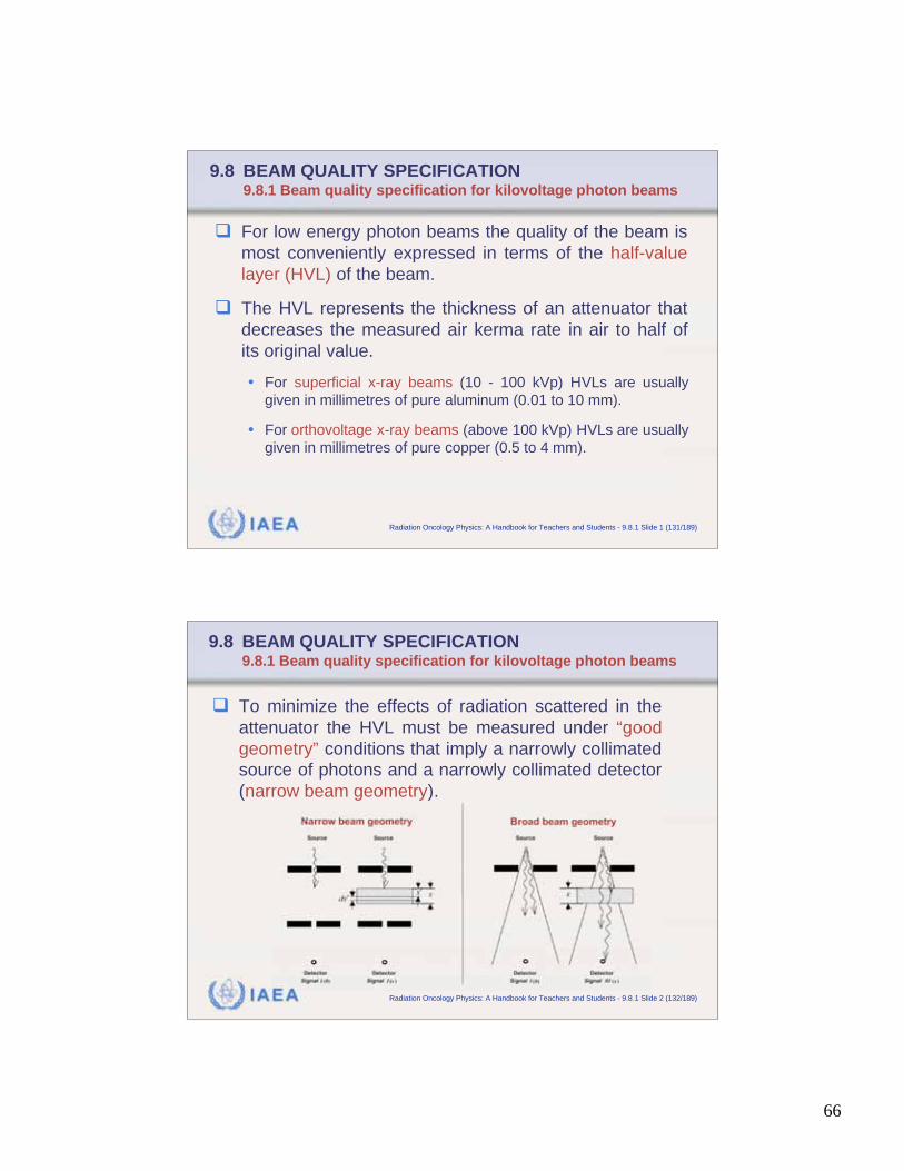
66
IAEA Radiation Oncology Physics: A Handbook for Teachers and Students - 9.8.1 Slide 1 (131/189)
9.8 BEAM QUALITY SPECIFICATION9.8.1 Beam quality specification for kilovoltage photon beams
For low energy photon beams the quality of the beam is
most conveniently expressed in terms of the half-value
layer (HVL) of the beam.
The HVL represents the thickness of an attenuator that
decreases the measured air kerma rate in air to half of
its original value.
• For superficial x-ray beams (10 - 100 kVp) HVLs are usually
given in millimetres of pure aluminum (0.01 to 10 mm).
• For orthovoltage x-ray beams (above 100 kVp) HVLs are usually
given in millimetres of pure copper (0.5 to 4 mm).
IAEA Radiation Oncology Physics: A Handbook for Teachers and Students - 9.8.1 Slide 2 (132/189)
9.8 BEAM QUALITY SPECIFICATION9.8.1 Beam quality specification for kilovoltage photon beams
To minimize the effects of radiation scattered in the
attenuator the HVL must be measured under “good
geometry” conditions that imply a narrowly collimated
source of photons and a narrowly collimated detector
(narrow beam geometry).
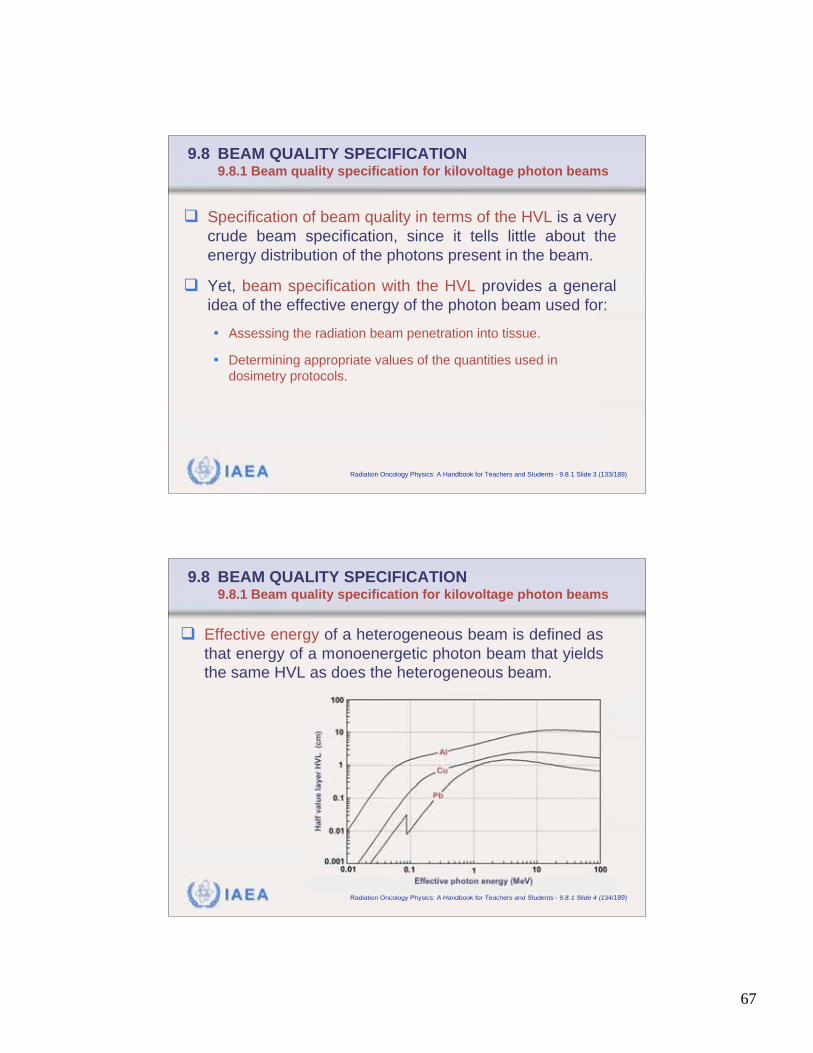
67
IAEA Radiation Oncology Physics: A Handbook for Teachers and Students - 9.8.1 Slide 3 (133/189)
9.8 BEAM QUALITY SPECIFICATION9.8.1 Beam quality specification for kilovoltage photon beams
Specification of beam quality in terms of the HVL is a very
crude beam specification, since it tells little about the
energy distribution of the photons present in the beam.
Yet, beam specification with the HVL provides a general
idea of the effective energy of the photon beam used for:
• Assessing the radiation beam penetration into tissue.
• Determining appropriate values of the quantities used in
dosimetry protocols.
IAEA Radiation Oncology Physics: A Handbook for Teachers and Students - 9.8.1 Slide 4 (134/189)
9.8 BEAM QUALITY SPECIFICATION9.8.1 Beam quality specification for kilovoltage photon beams
Effective energy of a heterogeneous beam is defined as
that energy of a monoenergetic photon beam that yields
the same HVL as does the heterogeneous beam.
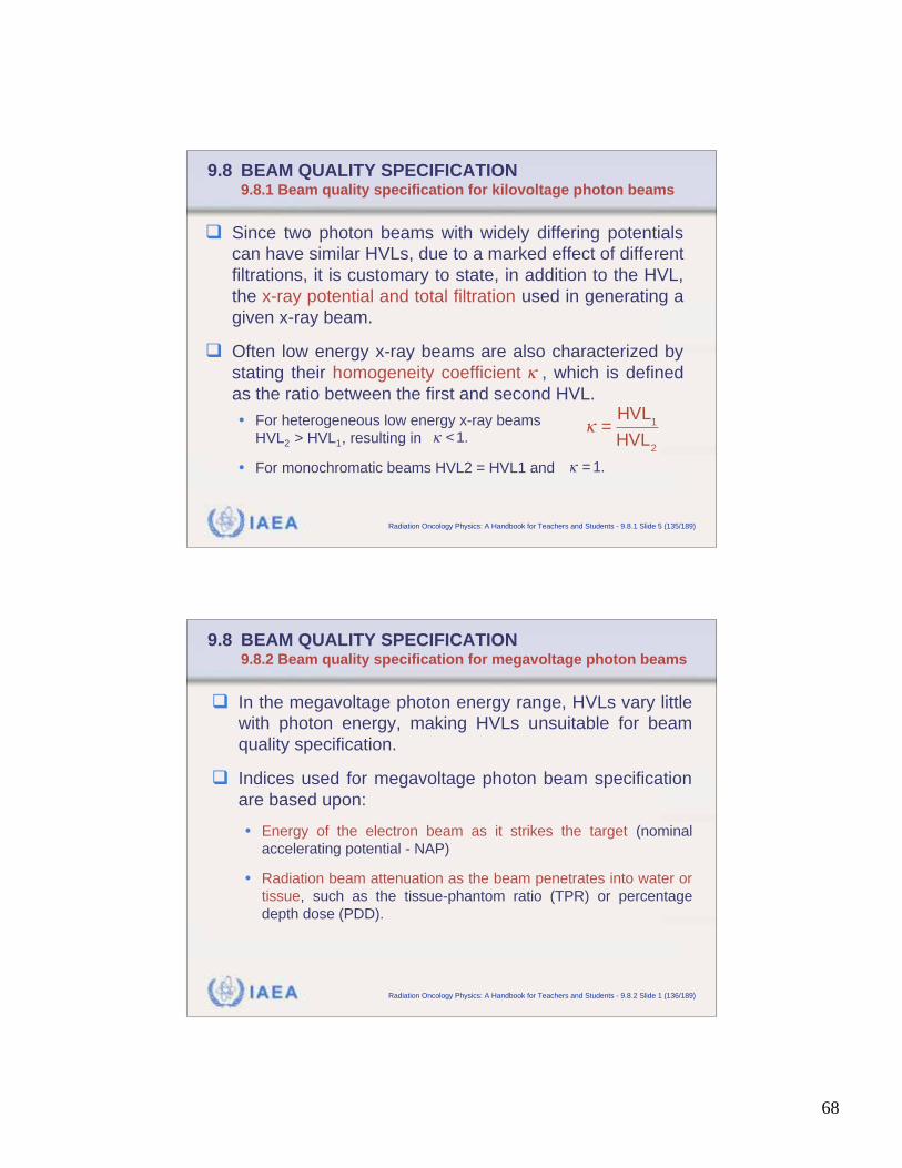
68
IAEA Radiation Oncology Physics: A Handbook for Teachers and Students - 9.8.1 Slide 5 (135/189)
9.8 BEAM QUALITY SPECIFICATION9.8.1 Beam quality specification for kilovoltage photon beams
Since two photon beams with widely differing potentials
can have similar HVLs, due to a marked effect of different
filtrations, it is customary to state, in addition to the HVL,
the x-ray potential and total filtration used in generating a
given x-ray beam.
Often low energy x-ray beams are also characterized by
stating their homogeneity coefficient , which is defined
as the ratio between the first and second HVL.
• For heterogeneous low energy x-ray beams
HVL2 > HVL1, resulting in
• For monochromatic beams HVL2 = HVL1 and
=HVL
1
HVL2
< 1.
= 1.
IAEA Radiation Oncology Physics: A Handbook for Teachers and Students - 9.8.2 Slide 1 (136/189)
9.8 BEAM QUALITY SPECIFICATION9.8.2 Beam quality specification for megavoltage photon beams
In the megavoltage photon energy range, HVLs vary little
with photon energy, making HVLs unsuitable for beam
quality specification.
Indices used for megavoltage photon beam specification
are based upon:
• Energy of the electron beam as it strikes the target (nominal
accelerating potential - NAP)
• Radiation beam attenuation as the beam penetrates into water or
tissue, such as the tissue-phantom ratio (TPR) or percentage
depth dose (PDD).
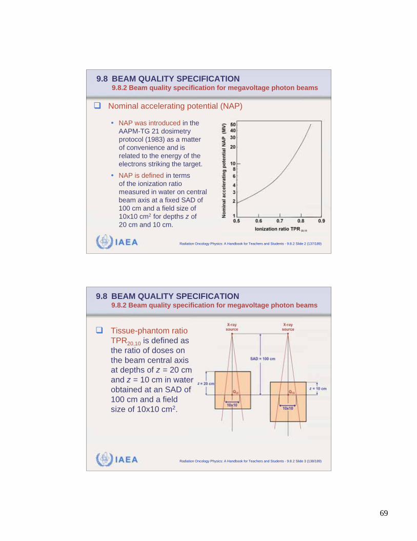
69
IAEA Radiation Oncology Physics: A Handbook for Teachers and Students - 9.8.2 Slide 2 (137/189)
9.8 BEAM QUALITY SPECIFICATION9.8.2 Beam quality specification for megavoltage photon beams
• NAP was introduced in the
AAPM-TG 21 dosimetry
protocol (1983) as a matter
of convenience and is
related to the energy of the
electrons striking the target.
• NAP is defined in terms
of the ionization ratio
measured in water on central
beam axis at a fixed SAD of
100 cm and a field size of
10x10 cm2 for depths z of
20 cm and 10 cm.
Nominal accelerating potential (NAP)
IAEA Radiation Oncology Physics: A Handbook for Teachers and Students - 9.8.2 Slide 3 (138/189)
9.8 BEAM QUALITY SPECIFICATION9.8.2 Beam quality specification for megavoltage photon beams
Tissue-phantom ratio
TPR20,10 is defined as
the ratio of doses on
the beam central axis
at depths of z = 20 cm
and z = 10 cm in water
obtained at an SAD of
100 cm and a field
size of 10x10 cm2.
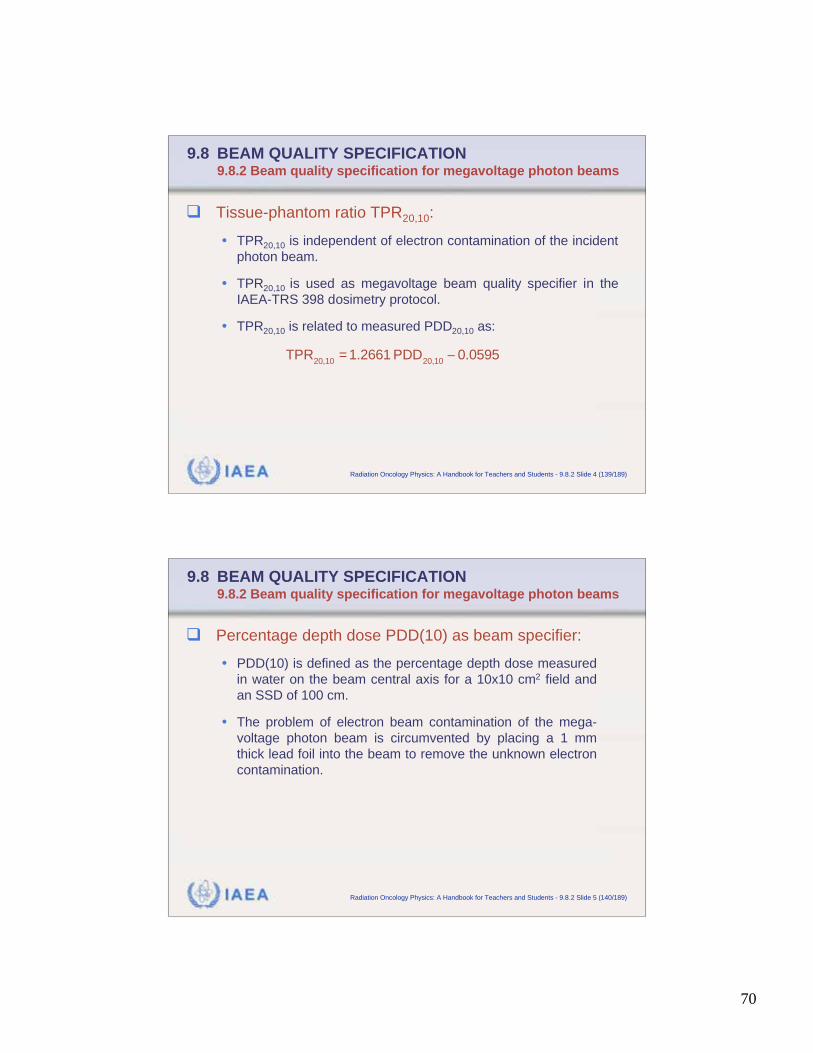
70
IAEA Radiation Oncology Physics: A Handbook for Teachers and Students - 9.8.2 Slide 4 (139/189)
9.8 BEAM QUALITY SPECIFICATION9.8.2 Beam quality specification for megavoltage photon beams
Tissue-phantom ratio TPR20,10:
• TPR20,10 is independent of electron contamination of the incident
photon beam.
• TPR20,10 is used as megavoltage beam quality specifier in the
IAEA-TRS 398 dosimetry protocol.
• TPR20,10 is related to measured PDD20,10 as:
TPR
20,10= 1.2661 PDD
20,100.0595
IAEA Radiation Oncology Physics: A Handbook for Teachers and Students - 9.8.2 Slide 5 (140/189)
9.8 BEAM QUALITY SPECIFICATION9.8.2 Beam quality specification for megavoltage photon beams
Percentage depth dose PDD(10) as beam specifier:
• PDD(10) is defined as the percentage depth dose measured
in water on the beam central axis for a 10x10 cm2 field and
an SSD of 100 cm.
• The problem of electron beam contamination of the mega-
voltage photon beam is circumvented by placing a 1 mm
thick lead foil into the beam to remove the unknown electron
contamination.
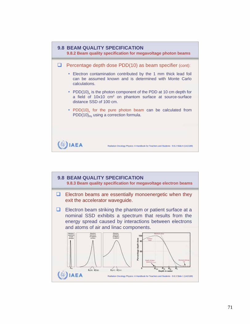
71
IAEA Radiation Oncology Physics: A Handbook for Teachers and Students - 9.8.2 Slide 6 (141/189)
9.8 BEAM QUALITY SPECIFICATION9.8.2 Beam quality specification for megavoltage photon beams
Percentage depth dose PDD(10) as beam specifier (cont):
• Electron contamination contributed by the 1 mm thick lead foil
can be assumed known and is determined with Monte Carlo
calculations.
• PDD(10)x is the photon component of the PDD at 10 cm depth for
a field of 10x10 cm2 on phantom surface at source-surface
distance SSD of 100 cm.
• PDD(10)x for the pure photon beam can be calculated from
PDD(10)Pb using a correction formula.
IAEA Radiation Oncology Physics: A Handbook for Teachers and Students - 9.8.3 Slide 1 (142/189)
9.8 BEAM QUALITY SPECIFICATION9.8.3 Beam quality specification for megavoltage electron beams
Electron beams are essentially monoenergetic when they
exit the accelerator waveguide.
Electron beam striking the phantom or patient surface at a
nominal SSD exhibits a spectrum that results from the
energy spread caused by interactions between electrons
and atoms of air and linac components.
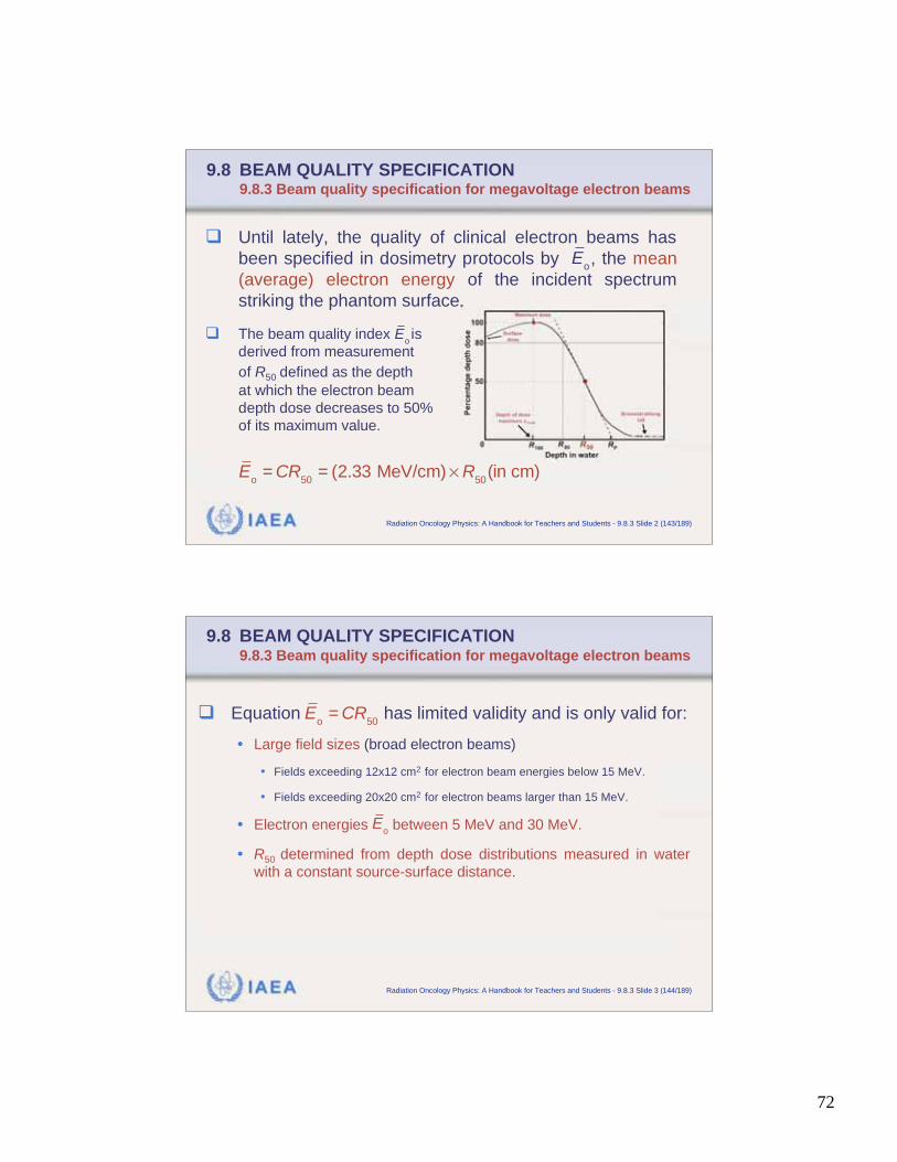
72
IAEA Radiation Oncology Physics: A Handbook for Teachers and Students - 9.8.3 Slide 2 (143/189)
9.8 BEAM QUALITY SPECIFICATION9.8.3 Beam quality specification for megavoltage electron beams
Until lately, the quality of clinical electron beams has
been specified in dosimetry protocols by , the mean
(average) electron energy of the incident spectrum
striking the phantom surface.
The beam quality index is
derived from measurement
of R50 defined as the depth
at which the electron beam
depth dose decreases to 50%
of its maximum value.
E
o
E
o
Eo= CR
50= (2.33 MeV/cm) R
50(in cm)
IAEA Radiation Oncology Physics: A Handbook for Teachers and Students - 9.8.3 Slide 3 (144/189)
9.8 BEAM QUALITY SPECIFICATION9.8.3 Beam quality specification for megavoltage electron beams
Equation has limited validity and is only valid for:
• Large field sizes (broad electron beams)
• Fields exceeding 12x12 cm2 for electron beam energies below 15 MeV.
• Fields exceeding 20x20 cm2 for electron beams larger than 15 MeV.
• Electron energies between 5 MeV and 30 MeV.
• R50 determined from depth dose distributions measured in water
with a constant source-surface distance.
E
o= CR
50
E
o
73
IAEA Radiation Oncology Physics: A Handbook for Teachers and Students - 9.8.3 Slide 4 (145/189)
9.8 BEAM QUALITY SPECIFICATION9.8.3 Beam quality specification for megavoltage electron beams
Percentage depth dose curves for clinical electron
beams are most commonly determined from ionization
measurements carried out in water or water equivalent
phantoms using ionization chambers or diodes.
• Percentage depth ionization curves measured with a diode
represent the PDD curve directly, since the mass collision
stopping power ratios silicon to water are essentially constant
with depth in a phantom (i.e., with electron beam energy).
• Percentage depth ionization curves measured with an ioni-
zation chamber must be corrected for gradient effects as well
as for variations in mass collision stopping power ratios water
to air with electron beam energy when determining the PDDs
from ionization measurements.
IAEA Radiation Oncology Physics: A Handbook for Teachers and Students - 9.8.3 Slide 5 (146/189)
9.8 BEAM QUALITY SPECIFICATION9.8.3 Beam quality specification for megavoltage electron beams
R50 may be determined from I50 (in cm), the 50% value
on the percentage depth ionization (PDI) curve,
measured with an ionization chamber in water as:
Recent dosimetry protocols use R50 directly as a beam
quality index for selecting stopping power ratios and
reference depths.
R
50= 1.029I
500.06 cm
for 2 cm I
5010 cm
R
50= 1.059I
500.37 cm
for I
50> 10 cm
74
IAEA Radiation Oncology Physics: A Handbook for Teachers and Students - 9.8.3 Slide 6 (147/189)
9.8 BEAM QUALITY SPECIFICATION9.8.3 Beam quality specification for megavoltage electron beams
The recent dosimetry protocols based on in-water
calibration by the IAEA (TRS 398) and the AAPM (TG 51)
have endorsed the choice of R50 as the quality index,
and all data are expressed in terms of R50.
The reference depth zref for electron beam calibration in
water is expressed in terms of R50 (in centimetres) as:
• The reference depth zref in water is close to the depth of dose
maximum zmax for beams with R50 < 4 cm
• zref > zmax for beams with
z
ref= 0.6R
500.1 cm
<o( 10 MeV).E
504 cm.R
IAEA Radiation Oncology Physics: A Handbook for Teachers and Students - 9.9.1 Slide 1 (148/189)
9.9 CALIBRATION OF MEGAVOLTAGE BEAMS: PRACTICAL ASPECT
9.9.1 MV photon beams: Air kerma in air calibration coefficient NK,Co
A cylindrical ionization chamber is used at a given depth
z in a water phantom (typically z is 5 cm or 10 cm).
Calibration is based on an air kerma in air calibration
coefficient NK,Co obtained in a cobalt-60 beam at a
standards laboratory.
The beam quality is specified with , the mean electron
energy on a phantom surface obtained from E
o
Eo= CR
50= (2.33 MeV/cm) R
50(in cm)
75
IAEA Radiation Oncology Physics: A Handbook for Teachers and Students - 9.9.1 Slide 2 (149/189)
9.9 CALIBRATION OF MEGAVOLTAGE BEAMS: PRACTICAL ASPECTS
9.9.1 MV photon beams: Air kerma in air calibration coefficient NK,Co
Bragg-Gray or Spencer-Attix cavity theory is used to deter-
mine the dose Dw(z) at the point of interest at depth z in a
water phantom from the signal MQ (charge) measured at
beam quality Q and corrected for influence quantities :
• ND,air is the cavity air calibration coefficient.
• sw,air is the restricted stopping power ratio water to air averaged
over the electron slowing down spectrum resulting from the
photon spectrum.
• pQ is the perturbation correction factor accounting for pertur-
bations caused by the chamber inserted into water phantom.
D
w(z) = M
Q N
D,air s
w,air p
Q= M
Q N
D,air s
w,air p
wall p
cel
IAEA Radiation Oncology Physics: A Handbook for Teachers and Students - 9.9.1 Slide 3 (150/189)
9.9 CALIBRATION OF MEGAVOLTAGE BEAMS: PRACTICAL ASPECTS
9.9.1 MV photon beams: Air kerma in air calibration coefficient NK,Co
Generally, the chamber correction factor pQ is a productof four perturbation factors: displacement, wall, centralelectrode, and fluence:
Of the four perturbation factors, only pwall and pcell applyfor air kerma in air based protocols and for MV photonbeams:
• The displacement effect resulting from insertion of an air cavityinto a phantom is accounted for by defining an effective point ofmeasurement Peff, thus pdis = 1.
• Cavity fluence perturbation correction factor pcav is unity in highenergy photon beams.
D
w(z) = M
Q N
D,air s
w,air p
wall p
cel pQ= (p
dis p
wall p
cel p
cav)
Q
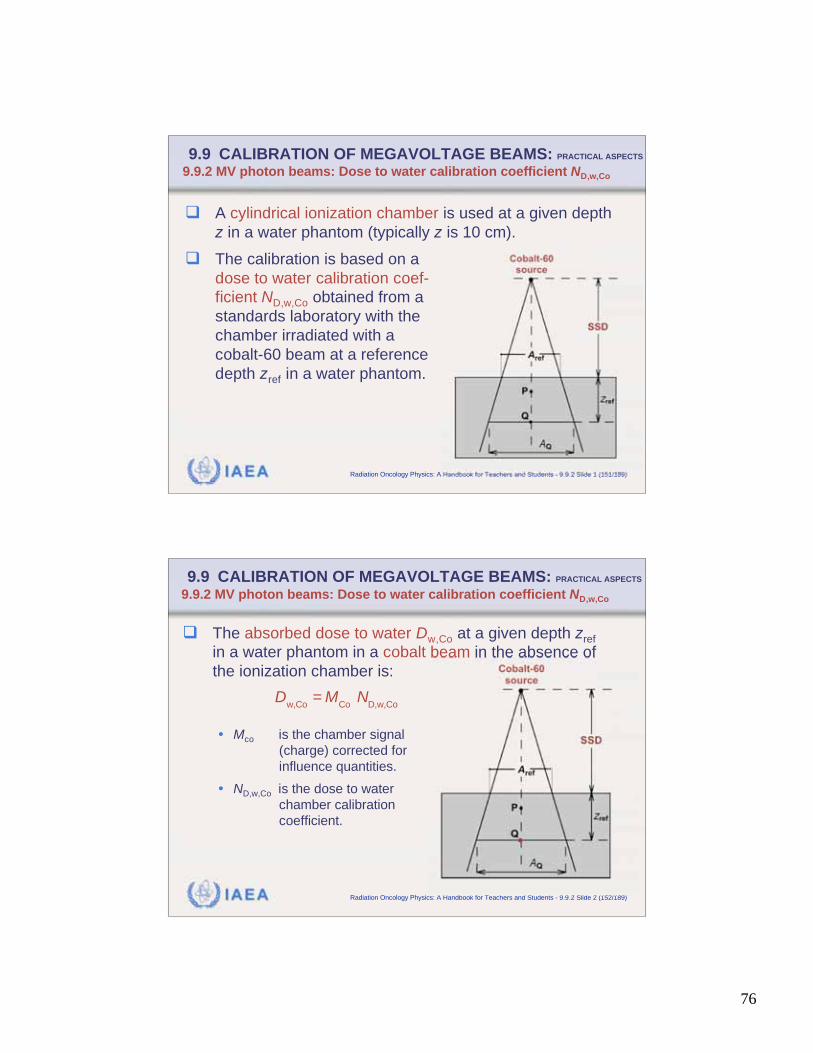
76
IAEA Radiation Oncology Physics: A Handbook for Teachers and Students - 9.9.2 Slide 1 (151/189)
9.9 CALIBRATION OF MEGAVOLTAGE BEAMS: PRACTICAL ASPECTS
9.9.2 MV photon beams: Dose to water calibration coefficient ND,w,Co
A cylindrical ionization chamber is used at a given depth
z in a water phantom (typically z is 10 cm).
The calibration is based on a
dose to water calibration coef-
ficient ND,w,Co obtained from a
standards laboratory with the
chamber irradiated with a
cobalt-60 beam at a reference
depth zref in a water phantom.
IAEA Radiation Oncology Physics: A Handbook for Teachers and Students - 9.9.2 Slide 2 (152/189)
9.9 CALIBRATION OF MEGAVOLTAGE BEAMS: PRACTICAL ASPECTS
9.9.2 MV photon beams: Dose to water calibration coefficient ND,w,Co
The absorbed dose to water Dw,Co at a given depth zref
in a water phantom in a cobalt beam in the absence of
the ionization chamber is:
• Mco is the chamber signal
(charge) corrected for
influence quantities.
• ND,w,Co is the dose to water
chamber calibration
coefficient.
D
w,Co= M
Co N
D,w,Co
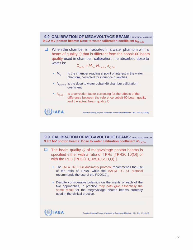
77
IAEA Radiation Oncology Physics: A Handbook for Teachers and Students - 9.9.2 Slide 3 (153/189)
9.9 CALIBRATION OF MEGAVOLTAGE BEAMS: PRACTICAL ASPECTS
9.9.2 MV photon beams: Dose to water calibration coefficient ND,w,Co
When the chamber is irradiated in a water phantom with a
beam of quality Q that is different from the cobalt-60 beam
quality used in chamber calibration, the absorbed dose to
water is:
• MQ is the chamber reading at point of interest in the water
phantom, corrected for influence quantities.
• ND,w,Co is the dose to water cobalt-60 chamber calibration
coefficient.
• kQ,Co is a correction factor correcting for the effects of the
difference between the reference cobalt-60 beam quality
and the actual beam quality Q.
D
w,Co= M
Co N
D,w,Co k
Q,Co
IAEA Radiation Oncology Physics: A Handbook for Teachers and Students - 9.9.2 Slide 3 (154/189)
9.9 CALIBRATION OF MEGAVOLTAGE BEAMS: PRACTICAL ASPECTS
9.9.2 MV photon beams: Dose to water calibration coefficient ND,w,Co
The beam quality Q of megavoltage photon beams is
specified either with a ratio of TPRs [TPR20,10(Q)] or
with the PDD [PDD(10,10x10,SSD,Q)x].
• The IAEA TRS 398 dosimetry protocol recommends the use
of the ratio of TPRs, while the AAPM TG 51 protocol
recommends the use of the PDD(10)x.
• Despite considerable polemics on the merits of each of the
two approaches, in practice they both give essentially the
same result for the megavoltage photon beams currently
used in the clinical practice.
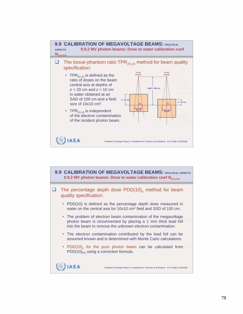
78
IAEA Radiation Oncology Physics: A Handbook for Teachers and Students - 9.9.2 Slide 4 (155/189)
9.9 CALIBRATION OF MEGAVOLTAGE BEAMS: PRACTICAL
ASPECTS 9.9.2 MV photon beams: Dose to water calibration coef
ND,w,Co
The tissue-phantom ratio TPR20,10 method for beam quality
specification:
• TPR20,10 is defined as the
ratio of doses on the beam
central axis at depths of
z = 20 cm and z = 10 cm
in water obtained at an
SAD of 100 cm and a field
size of 10x10 cm2.
• TPR20,10 is independent
of the electron contamination
of the incident photon beam.
IAEA Radiation Oncology Physics: A Handbook for Teachers and Students - 9.9.2 Slide 5 (156/189)
9.9 CALIBRATION OF MEGAVOLTAGE BEAMS: PRACTICAL ASPECTS
9.9.2 MV photon beams: Dose to water calibration coef ND,w,Co
The percentage depth dose PDD(10)x method for beam
quality specification:
• PDD(10) is defined as the percentage depth dose measured in
water on the central axis for 10x10 cm2 field and SSD of 100 cm.
• The problem of electron beam contamination of the megavoltage
photon beam is circumvented by placing a 1 mm thick lead foil
into the beam to remove the unknown electron contamination.
• The electron contamination contributed by the lead foil can be
assumed known and is determined with Monte Carlo calculations.
• PDD(10)x for the pure photon beam can be calculated from
PDD(10)Pb using a correction formula.
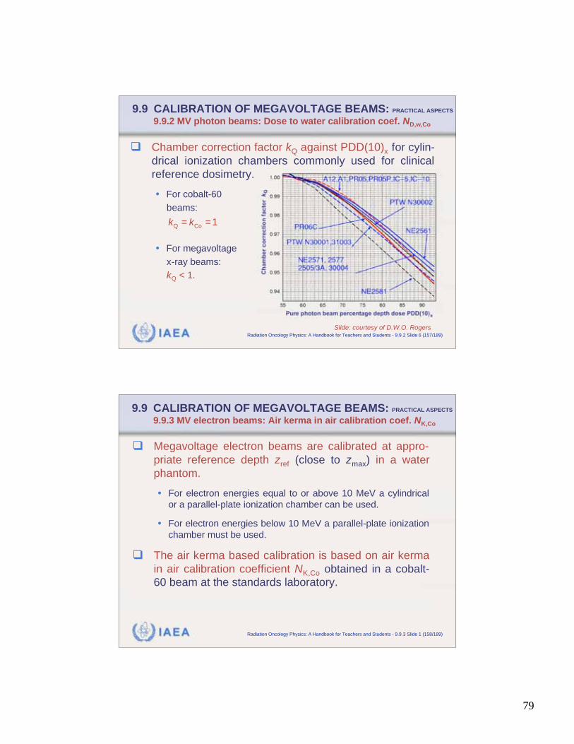
79
IAEA Radiation Oncology Physics: A Handbook for Teachers and Students - 9.9.2 Slide 6 (157/189)
9.9 CALIBRATION OF MEGAVOLTAGE BEAMS: PRACTICAL ASPECTS
9.9.2 MV photon beams: Dose to water calibration coef. ND,w,Co
Chamber correction factor kQ against PDD(10)x for cylin-
drical ionization chambers commonly used for clinical
reference dosimetry.
• For cobalt-60
beams:
• For megavoltage
x-ray beams:
kQ < 1.
Slide: courtesy of D.W.O. Rogers
= =Q Co
1k k
IAEA Radiation Oncology Physics: A Handbook for Teachers and Students - 9.9.3 Slide 1 (158/189)
9.9 CALIBRATION OF MEGAVOLTAGE BEAMS: PRACTICAL ASPECTS
9.9.3 MV electron beams: Air kerma in air calibration coef. NK,Co
Megavoltage electron beams are calibrated at appro-
priate reference depth zref (close to zmax) in a water
phantom.
• For electron energies equal to or above 10 MeV a cylindrical
or a parallel-plate ionization chamber can be used.
• For electron energies below 10 MeV a parallel-plate ionization
chamber must be used.
The air kerma based calibration is based on air kerma
in air calibration coefficient NK,Co obtained in a cobalt-
60 beam at the standards laboratory.
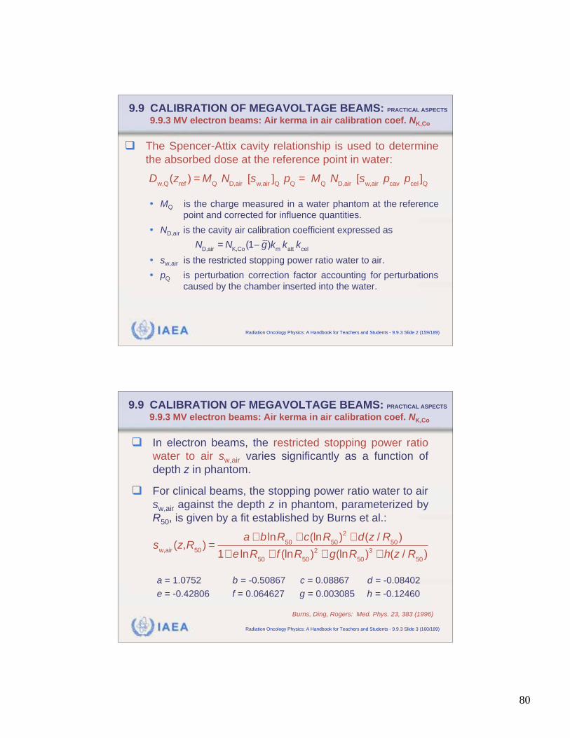
80
IAEA Radiation Oncology Physics: A Handbook for Teachers and Students - 9.9.3 Slide 2 (159/189)
9.9 CALIBRATION OF MEGAVOLTAGE BEAMS: PRACTICAL ASPECTS
9.9.3 MV electron beams: Air kerma in air calibration coef. NK,Co
The Spencer-Attix cavity relationship is used to determine
the absorbed dose at the reference point in water:
• MQ is the charge measured in a water phantom at the reference
point and corrected for influence quantities.
• ND,air is the cavity air calibration coefficient expressed as
• sw,air is the restricted stopping power ratio water to air.
• pQ is perturbation correction factor accounting for perturbations
caused by the chamber inserted into the water.
D
w,Q(z
ref) = M
Q N
D,air [s
w,air]Q
pQ
= MQ
ND,air
[sw,air
pcav
pcel
]Q
N
D,air= N
K,Co(1 g)k
m k
att k
cel
IAEA Radiation Oncology Physics: A Handbook for Teachers and Students - 9.9.3 Slide 3 (160/189)
9.9 CALIBRATION OF MEGAVOLTAGE BEAMS: PRACTICAL ASPECTS
9.9.3 MV electron beams: Air kerma in air calibration coef. NK,Co
In electron beams, the restricted stopping power ratio
water to air sw,air varies significantly as a function of
depth z in phantom.
For clinical beams, the stopping power ratio water to air
sw,air against the depth z in phantom, parameterized by
R50, is given by a fit established by Burns et al.:
a = 1.0752 b = -0.50867 c = 0.08867 d = -0.08402
e = -0.42806 f = 0.064627 g = 0.003085 h = -0.12460
sw,air
(z,R50
) =a + b lnR
50+ c(lnR
50)2
+ d(z / R50
)
1+ e lnR50
+ f (lnR50
)2+ g(lnR
50)3
+ h(z / R50
)
Burns, Ding, Rogers: Med. Phys. 23, 383 (1996)
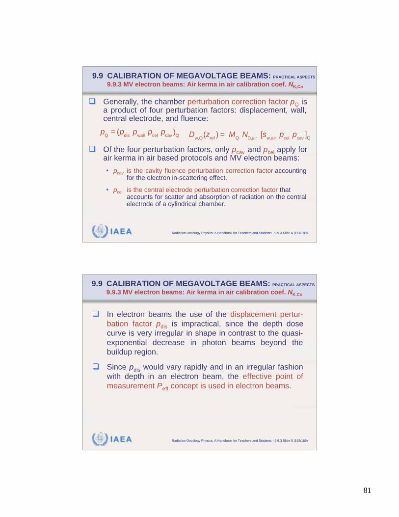
81
IAEA Radiation Oncology Physics: A Handbook for Teachers and Students - 9.9.3 Slide 4 (161/189)
9.9 CALIBRATION OF MEGAVOLTAGE BEAMS: PRACTICAL ASPECTS
9.9.3 MV electron beams: Air kerma in air calibration coef. NK,Co
Generally, the chamber perturbation correction factor pQ isa product of four perturbation factors: displacement, wall,central electrode, and fluence:
Of the four perturbation factors, only pcav and pcel apply forair kerma in air based protocols and MV electron beams:
• pcav is the cavity fluence perturbation correction factor accountingfor the electron in-scattering effect.
• pcel is the central electrode perturbation correction factor that accounts for scatter and absorption of radiation on the centralelectrode of a cylindrical chamber.
pQ= (p
dis p
wall p
cel p
cav)
Q D
w,Q(z
ref) = M
Q N
D,air [s
w,air p
cel p
cav]Q
IAEA Radiation Oncology Physics: A Handbook for Teachers and Students - 9.9.3 Slide 5 (162/189)
9.9 CALIBRATION OF MEGAVOLTAGE BEAMS: PRACTICAL ASPECTS
9.9.3 MV electron beams: Air kerma in air calibration coef. NK,Co
In electron beams the use of the displacement pertur-
bation factor pdis is impractical, since the depth dose
curve is very irregular in shape in contrast to the quasi-
exponential decrease in photon beams beyond the
buildup region.
Since pdis would vary rapidly and in an irregular fashion
with depth in an electron beam, the effective point of
measurement Peff concept is used in electron beams.
82
IAEA Radiation Oncology Physics: A Handbook for Teachers and Students - 9.9.3 Slide 6 (163/189)
9.9 CALIBRATION OF MEGAVOLTAGE BEAMS: PRACTICAL ASPECTS
9.9.3 MV electron beams: Air kerma in air calibration coef. NK,Co
The wall correction factor pwall is considered unity in
electron beam dosimetry.
Instead of pdis, the effective point of measurement Peff
concept is universally employed in electron beams:
• For parallel-plate chambers the effective point of measu-
rement is located on the inner surface of the window and no
gradient correction is required.
• For cylindrical ionization chambers the effective point of
measurement is located 0.5r upstream from the chamber
centre with r the chamber inner radius.
IAEA Radiation Oncology Physics: A Handbook for Teachers and Students - 9.9.4 Slide 1 (164/189)
9.9 CALIBRATION OF MEGAVOLTAGE BEAMS: PRACTICAL ASPECTS
9.9.4 MV electron beams: Dose to water calibration coef. ND,w,Co
Megavoltage electron beams are calibrated in a water
phantom at appropriate reference depth zref with a field
of 10x10 cm2.
• For electron energies equal to or above 10 MeV a cylindrical or
a parallel-plate ionization chamber can be used.
• For electron energies below 10 MeV a parallel-plate ionization
chamber must be used.
Water is recommended as the reference medium. For
electron energies below 10 MeV plastic phantom may
be used but all depths must be scaled appropriately.
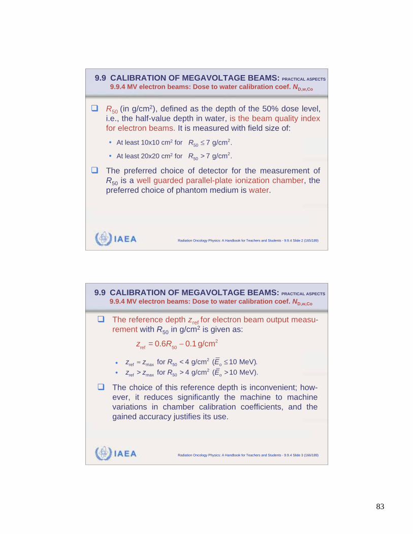
83
IAEA Radiation Oncology Physics: A Handbook for Teachers and Students - 9.9.4 Slide 2 (165/189)
9.9 CALIBRATION OF MEGAVOLTAGE BEAMS: PRACTICAL ASPECTS
9.9.4 MV electron beams: Dose to water calibration coef. ND,w,Co
R50 (in g/cm2), defined as the depth of the 50% dose level,
i.e., the half-value depth in water, is the beam quality index
for electron beams. It is measured with field size of:
• At least 10x10 cm2 for
• At least 20x20 cm2 for
The preferred choice of detector for the measurement of
R50 is a well guarded parallel-plate ionization chamber, the
preferred choice of phantom medium is water.
250 7 g/cm .R
>2
50 7 g/cm .R
IAEA Radiation Oncology Physics: A Handbook for Teachers and Students - 9.9.4 Slide 3 (166/189)
9.9 CALIBRATION OF MEGAVOLTAGE BEAMS: PRACTICAL ASPECTS
9.9.4 MV electron beams: Dose to water calibration coef. ND,w,Co
The reference depth zref for electron beam output measu-
rement with R50 in g/cm2 is given as:
•
•
The choice of this reference depth is inconvenient; how-
ever, it reduces significantly the machine to machine
variations in chamber calibration coefficients, and the
gained accuracy justifies its use.
zref= 0.6R
500.1 g/cm2
<2
max 50 oref for 4 g/cm ( 10 MeV).z z R E
> > >2
max 50 oref for 4 g/cm ( 10 MeV).z z R E
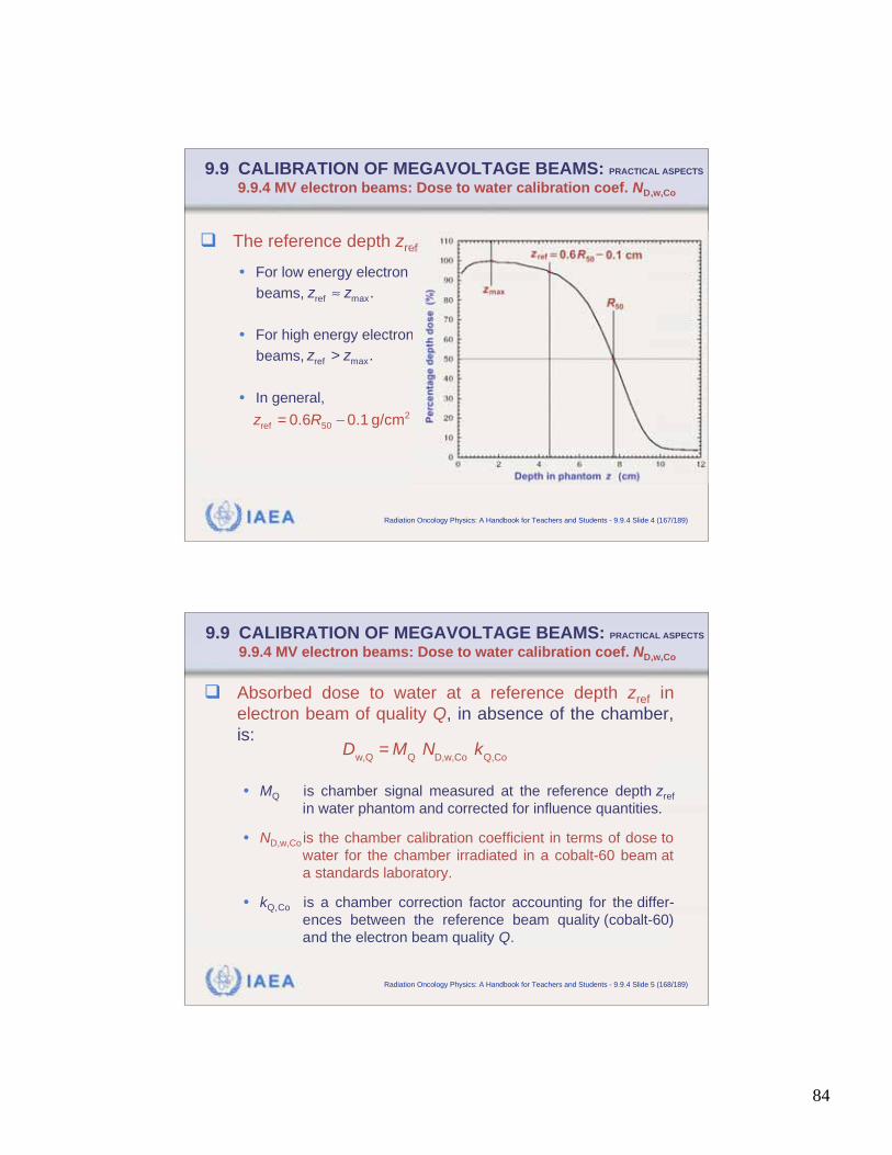
84
IAEA Radiation Oncology Physics: A Handbook for Teachers and Students - 9.9.4 Slide 4 (167/189)
9.9 CALIBRATION OF MEGAVOLTAGE BEAMS: PRACTICAL ASPECTS
9.9.4 MV electron beams: Dose to water calibration coef. ND,w,Co
The reference depth zref
• For low energy electron
beams,
• For high energy electron
beams,
• In general,
maxref.z z
>maxref
.z z
=2
50ref 0.6 0.1 g/cmz R
IAEA Radiation Oncology Physics: A Handbook for Teachers and Students - 9.9.4 Slide 5 (168/189)
9.9 CALIBRATION OF MEGAVOLTAGE BEAMS: PRACTICAL ASPECTS
9.9.4 MV electron beams: Dose to water calibration coef. ND,w,Co
Absorbed dose to water at a reference depth zref in
electron beam of quality Q, in absence of the chamber,
is:
• MQ is chamber signal measured at the reference depth zref
in water phantom and corrected for influence quantities.
• ND,w,Co is the chamber calibration coefficient in terms of dose to
water for the chamber irradiated in a cobalt-60 beam at
a standards laboratory.
• kQ,Co is a chamber correction factor accounting for the differ-
ences between the reference beam quality (cobalt-60)
and the electron beam quality Q.
D
w,Q= M
Q N
D,w,Co k
Q,Co
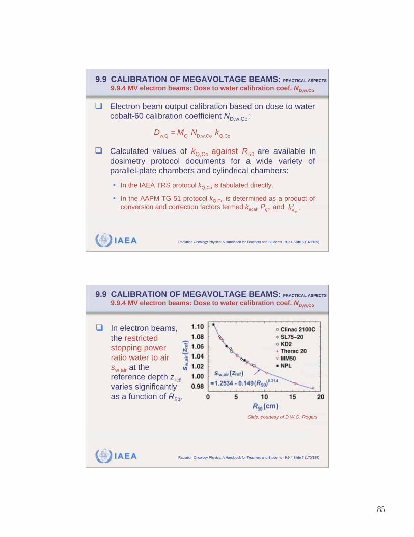
85
IAEA Radiation Oncology Physics: A Handbook for Teachers and Students - 9.9.4 Slide 6 (169/189)
9.9 CALIBRATION OF MEGAVOLTAGE BEAMS: PRACTICAL ASPECTS
9.9.4 MV electron beams: Dose to water calibration coef. ND,w,Co
Electron beam output calibration based on dose to water
cobalt-60 calibration coefficient ND,w,Co:
Calculated values of kQ,Co against R50 are available in
dosimetry protocol documents for a wide variety of
parallel-plate chambers and cylindrical chambers:
• In the IAEA TRS protocol kQ,Co is tabulated directly.
• In the AAPM TG 51 protocol kQ,Co is determined as a product of
conversion and correction factors termed kecal, Pgr, and
D
w,Q= M
Q N
D,w,Co k
Q,Co
k
R50
.
IAEA Radiation Oncology Physics: A Handbook for Teachers and Students - 9.9.4 Slide 7 (170/189)
9.9 CALIBRATION OF MEGAVOLTAGE BEAMS: PRACTICAL ASPECTS
9.9.4 MV electron beams: Dose to water calibration coef. ND,w,Co
In electron beams,
the restricted
stopping power
ratio water to air
sw,air at the
reference depth zref
varies significantly
as a function of R50.
Slide: courtesy of D.W.O. Rogers
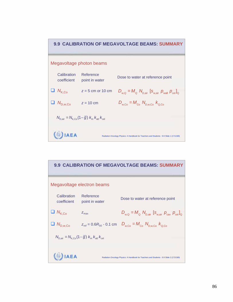
86
IAEA Radiation Oncology Physics: A Handbook for Teachers and Students - 9.9 Slide 1 (171/189)
9.9 CALIBRATION OF MEGAVOLTAGE BEAMS: SUMMARY
Megavoltage photon beams
Calibration Reference
coefficient point in water
NK,Co z = 5 cm or 10 cm
ND,w,Co z = 10 cm
D
w,Q= M
Q N
D,air [s
w,air p
wall p
cel]Q
D
w,Co= M
Co N
D,w,Co k
Q,Co
Dose to water at reference point
=D,air m att celK,Co(1 ) N N g k k k
IAEA Radiation Oncology Physics: A Handbook for Teachers and Students - 9.9 Slide 2 (172/189)
9.9 CALIBRATION OF MEGAVOLTAGE BEAMS: SUMMARY
Megavoltage electron beams
Calibration Reference
coefficient point in water
NK,Co zmax
ND,w,Co zref = 0.6R50 - 0.1 cm
D
w,Q= M
Q N
D,air [s
w,air p
cav p
cel]Q
D
w,Co= M
Co N
D,w,Co k
Q,Co
Dose to water at reference point
=D,air m att celK,Co(1 ) N N g k k k
87
IAEA Radiation Oncology Physics: A Handbook for Teachers and Students - 9.10 Slide 1 (173/189)
9.10 KILOVOLTAGE DOSIMETRY 9.10.1. Specific features of kilovoltage beams
Despite the advent of megavoltage photon and electron
beams, kilovoltage beams are still in widespread use in
treatment of superficial lesions.
When kilovoltage x rays interact with the medium, the
secondary electrons produced through photoelectric and
Compton interactions have very short ranges due to their
low initial energy coupled with the increase in the
collision stopping power at low kinetic energies.
IAEA Radiation Oncology Physics: A Handbook for Teachers and Students - 9.10.1 Slide 1 (174/189)
9.10 KILOVOLTAGE DOSIMETRY 9.10.1. Specific features of kilovoltage beams
There are several notable differences between kilo-
voltage and megavoltage beams:
• The Bragg-Gray principle no longer applies because the
electron fluence in the air cavity of the ionization chamber is
not exclusively determined by electron interactions in the
surrounding medium.
• Absorbed dose can be equated to collision kerma to a very
good approximation owing to the short electron ranges.
• Absorbed dose and kerma are essentially equivalent, since
radiation losses can be ignored in low atomic number
materials.
88
IAEA Radiation Oncology Physics: A Handbook for Teachers and Students - 9.10.1 Slide 2 (175/189)
9.10 KILOVOLTAGE DOSIMETRY 9.10.1. Specific features of kilovoltage beams
Calibration coefficient for kilovoltage radiation dosimetry
is determined with reference to a free air standard
ionization chamber at a set of kilovoltage radiation
quantities, in contrast to a single air kerma in air cali-
bration coefficient at cobalt-60 applied for all mega-
voltage beams.
Since the wall thickness of a typical cylindrical ionization
chamber is larger than the range of secondary electrons
released in the wall, the chamber acts as a kerma
detector even when used in a phantom.
IAEA Radiation Oncology Physics: A Handbook for Teachers and Students - 9.10.1 Slide 3 (176/189)
9.10 KILOVOLTAGE DOSIMETRY 9.10.1. Specific features of kilovoltage beams
Kilovoltage beam quality Q is specified in terms of half-
value layer HVL, generally expressed:
• In millimetres of aluminum for superficial x-ray beams.
• In millimetres of copper for orthovoltage x-ray beams.
Beams with widely differing tube potentials may have
similar HVL, due to marked effect of different filtrations.
User determines the HVL of the beams of interest and
then chooses the air kerma calibration coefficient NK
values for the calibrated chamber for the beam using
the calibration curve supplied by standards laboratory.
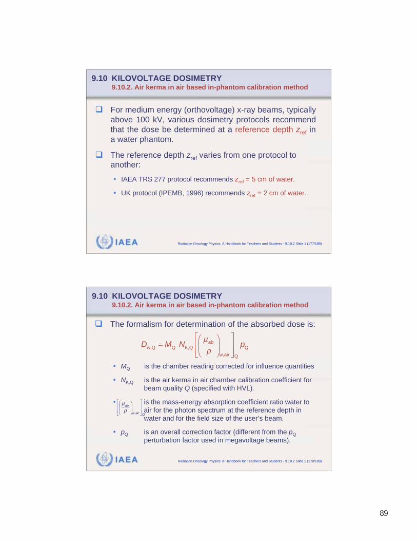
89
IAEA Radiation Oncology Physics: A Handbook for Teachers and Students - 9.10.2 Slide 1 (177/189)
9.10 KILOVOLTAGE DOSIMETRY 9.10.2. Air kerma in air based in-phantom calibration method
For medium energy (orthovoltage) x-ray beams, typically
above 100 kV, various dosimetry protocols recommend
that the dose be determined at a reference depth zref in
a water phantom.
The reference depth zref varies from one protocol to
another:
• IAEA TRS 277 protocol recommends zref = 5 cm of water.
• UK protocol (IPEMB, 1996) recommends zref = 2 cm of water.
IAEA Radiation Oncology Physics: A Handbook for Teachers and Students - 9.10.2 Slide 2 (178/189)
9.10 KILOVOLTAGE DOSIMETRY 9.10.2. Air kerma in air based in-phantom calibration method
The formalism for determination of the absorbed dose is:
• MQ is the chamber reading corrected for influence quantities
• NK,Q is the air kerma in air chamber calibration coefficient for
beam quality Q (specified with HVL).
• is the mass-energy absorption coefficient ratio water to
air for the photon spectrum at the reference depth in
water and for the field size of the user’s beam.
• pQ is an overall correction factor (different from the pQ
perturbation factor used in megavoltage beams).
ab
w,Q Q K,Q Q
w,air Q
D M N pμ
=
μab
w,air Q
90
IAEA Radiation Oncology Physics: A Handbook for Teachers and Students - 9.10.3 Slide 1 (179/189)
9.10 KILOVOLTAGE DOSIMETRY 9.10.3. Air kerma in air based backscatter method
Clinically, the dose for low energy (superficial) x rays is
most often prescribed for the skin surface (just below
skin surface where CPE is established).
The calibration process is as follows:
• A calibrated chamber is positioned free in air (no phantom) at
the position corresponding to the centre of the field on the
patient’s skin surface.
• Chamber reading yields the air kerma in air (Kair)air.
• (Kair)air is converted into dose to water at the surface of the
phantom at the field size of interest.
IAEA Radiation Oncology Physics: A Handbook for Teachers and Students - 9.10.3 Slide 2 (180/189)
9.10 KILOVOLTAGE DOSIMETRY 9.10.3. Air kerma in air based backscatter method
The theoretical route is as follows:
• The air kerma in air (Kair)air is converted into water kerma in air
(Kw)air through the mass-energy absorption coefficient ratio water
to air , but still under free in air conditions (i.e., for the
primary spectrum). This has the advantage that is
independent of field size.
• The water kerma in air (Kw)air is then converted into water kerma
in water (Kw)w at the surface of the water phantom by multiplying
(Kw)air with the backscatter factor BSF for the given field size, HVL
and SSD used.
ab w,air( / )μ
μab w,air( / )
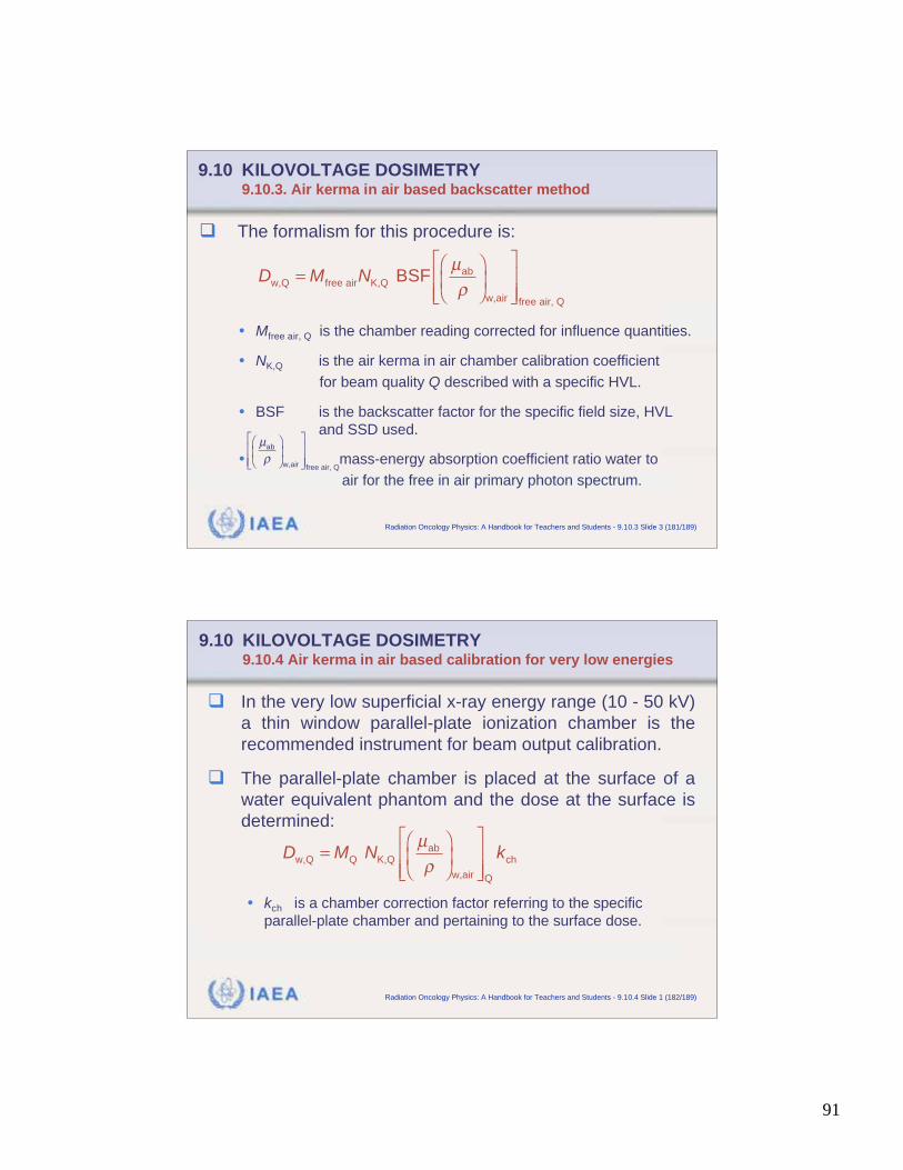
91
IAEA Radiation Oncology Physics: A Handbook for Teachers and Students - 9.10.3 Slide 3 (181/189)
9.10 KILOVOLTAGE DOSIMETRY 9.10.3. Air kerma in air based backscatter method
The formalism for this procedure is:
• Mfree air, Q is the chamber reading corrected for influence quantities.
• NK,Q is the air kerma in air chamber calibration coefficient
for beam quality Q described with a specific HVL.
• BSF is the backscatter factor for the specific field size, HVL
and SSD used.
• mass-energy absorption coefficient ratio water to
air for the free in air primary photon spectrum.
ab
w,Q free air K,Q
w,air free air, Q
BSFD M Nμ
=
μab
w,air free air, Q
IAEA Radiation Oncology Physics: A Handbook for Teachers and Students - 9.10.4 Slide 1 (182/189)
9.10 KILOVOLTAGE DOSIMETRY 9.10.4 Air kerma in air based calibration for very low energies
In the very low superficial x-ray energy range (10 - 50 kV)
a thin window parallel-plate ionization chamber is the
recommended instrument for beam output calibration.
The parallel-plate chamber is placed at the surface of a
water equivalent phantom and the dose at the surface is
determined:
• kch is a chamber correction factor referring to the specific
parallel-plate chamber and pertaining to the surface dose.
ab
w,Q Q K,Q ch
w,air Q
D M N kμ
=
92
IAEA Radiation Oncology Physics: A Handbook for Teachers and Students - 9.10.5 Slide 1 (183/189)
9.10 KILOVOLTAGE DOSIMETRY 9.10.5. Absorbed dose to water based calibration method
Standards of absorbed dose to water in the kilovoltage
x-ray range are not generally available.
• However, it is possible to derive calibration coefficients in terms
of absorbed dose to water from air kerma in air calibration
coefficients using one of the accepted dosimetry protocols.
• Thus, any calibration laboratory with standards of air kerma in
air can in this way derive calibration coefficients in terms of
absorbed dose to water thereby unifying and standardizing the
methodology.
IAEA Radiation Oncology Physics: A Handbook for Teachers and Students - 9.11.1 Slide 1 (184/189)
9.11 ERROR AND UNCERTAINTY ANALYSIS
9.11.1. Errors and uncertainties
A measurement error is defined as the difference
between the measured value of a measurand and the
true value.
An error carries a sign and a correction factor may be
associated with it.
When the error is known, the true value of the
measurand can be calculated from the measured
value.
93
IAEA Radiation Oncology Physics: A Handbook for Teachers and Students - 9.11.1 Slide 2 (185/189)
9.11 ERROR AND UNCERTAINTY ANALYSIS
9.11.1. Errors and uncertainties
An uncertainty associated with a measurement is a
parameter that characterizes the dispersion of the
values that can be attributed to a measurand.
The value of the uncertainty:
• Is usually an estimated standard deviation.
• Has no sign.
• Is assumed to be symmetrical with respect to the estimated
value of the quantity.
Uncertainty is a measure of our lack of exact know-
ledge after all recognized systematic effects have
been eliminated by applying appropriate corrections.
IAEA Radiation Oncology Physics: A Handbook for Teachers and Students - 9.11.2 Slide 1 (186/189)
9.11 ERROR AND UNCERTAINTY ANALYSIS
9.11.2. Classification of uncertainties
Uncertainties of measurements are expressed as relative
standard uncertainties, and the evaluation of standard
uncertainties is classified into two types: A and B.
• Type A uncertainties are inherently random and are obtained by a
statistical analysis of a series of observations. A type A
uncertainty corresponds to the standard error on the mean of a set
of observations at the 68% confidence level.
• Type B uncertainties are determined through other than stati-
stical, often subjective, methods and account for systematic
effects in the determination of a quantity.
1
94
IAEA Radiation Oncology Physics: A Handbook for Teachers and Students - 9.11.3 Slide 1 (187/189)
9.11 ERROR AND UNCERTAINTY ANALYSIS
9.11.3. Uncertainties in the calibration chain
An analysis of uncertainties on the calculated values of
the beam quality conversion factors kQ for photon and
electron beams has shown the following estimated
relative standard uncertainties:
• For photon beams and cobalt-60 calibration technique: 1%
• For electron beams and cobalt-60 calibration technique: 1.2%
for cylindrical chambers and 1.7% for parallel-plate chambers.
• For electron beams and cross-calibration technique in an
electron beam: 0.9% for cylindrical chambers and 0.6% for
parallel-plate chambers.
IAEA Radiation Oncology Physics: A Handbook for Teachers and Students - 9.11.3 Slide 2 (188/189)
9.11 ERROR AND UNCERTAINTY ANALYSIS
9.11.3. Uncertainties in the calibration chain
To obtain the total uncertainty on beam output cali-
bration, the uncertainty on kQ must be combined with
uncertainties on other quantities, such as:
• The absorbed dose calibration coefficient at cobalt-60 or in a
high energy electron beam, if a cross cali-bration technique is
used.
• In-phantom measurement of absorbed dose in the clinic.
95
IAEA Radiation Oncology Physics: A Handbook for Teachers and Students - 9.11.3 Slide 3 (189/189)
9.11 ERROR AND UNCERTAINTY ANALYSIS
9.11.3. Uncertainties in the calibration chain
Some of the issues related to in-phantom measurement
of absorbed dose in the clinic comprise type A and type
B uncertainties:
• Positioning of the chamber in the water phantom.
• Positioning of the water phantom into the radiation beam.
• Temperature measurement.
• Pressure measurement.
• Determination of ion recombination.
• Determination of polarity effect.
• Electrometer correction factor (if present).
• Linac stability during the calibration process.