Embed Size (px)
Citation preview
Chapter 8 Perception
Part 2 8.2 Physics and Principles of Radiative Sensors
Mobile Robotics - Prof Alonzo Kelly, CMU RI 1

Outline • 8.2 Physics and Principles of Radiative Sensors
– 8.2.1 Radiative Sensors – 8.2.2 Techniques for Range Sensing – 8.2.3 Radiation – 8.2.4 Lenses, Filters, and Mirrors – Summary
Mobile Robotics - Prof Alonzo Kelly, CMU RI 2

Outline • 8.2 Physics and Principles of Radiative Sensors
– 8.2.1 Radiative Sensors – 8.2.2 Techniques for Range Sensing – 8.2.3 Radiation – 8.2.4 Lenses, Filters, and Mirrors – Summary
Mobile Robotics - Prof Alonzo Kelly, CMU RI 3

Radiative Sensors - Introduction • Most sensors are either:
– contact – noncontact (radiative) – inertial
• In this section, concentrate on radiative ones.
Mobile Robotics - Prof Alonzo Kelly, CMU RI 4
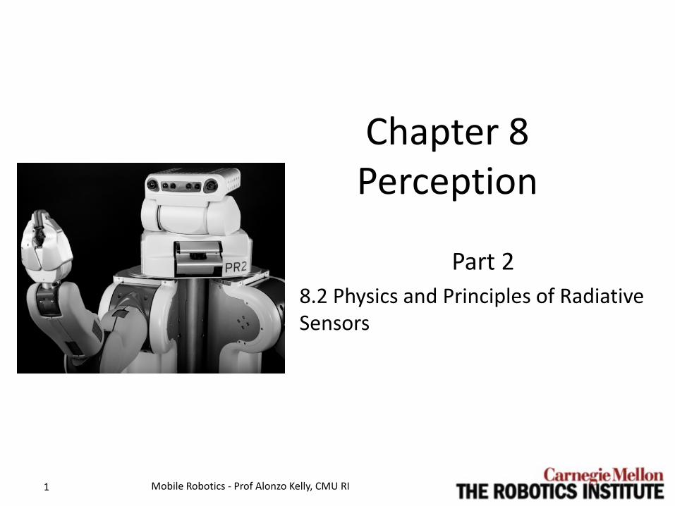
Radiative Sensors - Uses • Path planning
– where do I go next? • Navigation
– where am I? • Obstacle detection and avoidance
– is that an obstacle? • Object recognition
– is it an animal or a rock? • Mapping
– where are all the nasty poisons? • Teleoperation
– lets operator drive vehicle remotely • Manipulation
– allows intelligent grasping etc.
Mobile Robotics - Prof Alonzo Kelly, CMU RI 5

Radiative Sensors - Tradeoffs • Major advantages are:
– wide spatial field of view – provides lookahead in time (enables prediction) – Perceives while avoiding contact with environment
• Major disadvantages are: – sometimes massive computational load – physics of radiation can be inconvenient – problem of “perception”
Mobile Robotics - Prof Alonzo Kelly, CMU RI 6

8.2.1.1 Classification of Radiative Sensors • Passive/active
– passive uses ambient radiation
– active emits own radiation • Imaging/nonimaging
– imaging generates an image
– nonimaging generates a single “pixel”
• Scanning/nonscanning – scanning sensors are
moved over a scene – nonscanning sensors have
sensor array
• Proximity/ranging (range resolution) – proximity is binary
detector – ranging gives range value – “shape” means relative
range • Principle of operation
– triangulation – time of flight – scene constraint – interferometry
• Radiation used – electromagnetic – sound
Mobile Robotics - Prof Alonzo Kelly, CMU RI 7

8.2.1.2 Classification of Ranging Sensors
Mobile Robotics - Prof Alonzo Kelly, CMU RI 8
Ranging Techniques
Active Triangulation •Point •Line •Grid
Passive Triangulation •Stereo •Motion Stereo •Known Object •Shape From X
Time of Flight •Pulsed •AM-CW •FM-CW
See next section for details….

Outline • 8.2 Physics and Principles of Radiative Sensors
– 8.2.1 Radiative Sensors – 8.2.2 Techniques for Range Sensing – 8.2.3 Radiation – 8.2.4 Lenses, Filters, and Mirrors – Summary
Mobile Robotics - Prof Alonzo Kelly, CMU RI 9

8.2.2.1 Triangulation • General:
– Inverts the parallax effect of two separated views. – All techniques suffer “missing parts” problem. – Choice of sensor separation causes tradeoff:
• Better range resolution (+) causes more missing parts (-)
– All have uncertainty increasing with range
Mobile Robotics - Prof Alonzo Kelly, CMU RI 10

8.2.2.1.1 Passive Triangulation • Both forms rely on:
– scene texture – ambient illumination (cf
night/shadows)
• Case 1: Known Object
• Passivity is both a strength and a weakness.
• Case 2: Passive triangulation (“Stereo”) – major issue: correspondence
(reduces efficiency)
Mobile Robotics - Prof Alonzo Kelly, CMU RI 11
camera
camera
Passive - Stereo
camera
Passive – Known Object

8.2.2.1.2 Active Triangulation • Emit and sense from
two different places.
Mobile Robotics - Prof Alonzo Kelly, CMU RI 12
Missing Parts problem is illustrated here.
camera
Active

8.2.2.2 Time Of Flight • Advantages:
– (+) No missing parts problem (negligible or no baseline)
– (0) BUT, scene can still self-occlude – (+) No correspondence problem – (+) Accuracy basically independent of range (esp.
pulsed) • Disadvantages
– (-) Complicated, expensive, often non solid state hardware.
– (-) easy to detect by others.
Mobile Robotics - Prof Alonzo Kelly, CMU RI 13

8.2.2.2.1 Pulsed Time of Flight • Resolution comparatively low for high wave
speeds (e.g. light) • Because … measuring subnanosecond TOF
requires expensive electronics
Mobile Robotics - Prof Alonzo Kelly, CMU RI 14
transmitter/ receiver
2tcR ∆
=
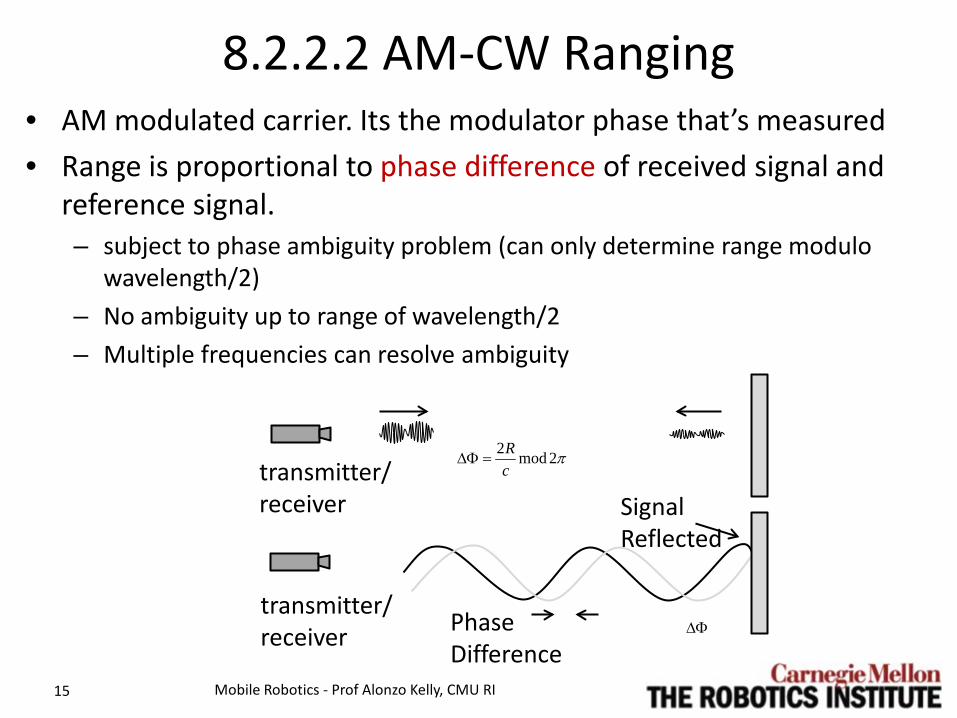
8.2.2.2 AM-CW Ranging • AM modulated carrier. Its the modulator phase that’s measured • Range is proportional to phase difference of received signal and
reference signal. – subject to phase ambiguity problem (can only determine range modulo
wavelength/2) – No ambiguity up to range of wavelength/2 – Multiple frequencies can resolve ambiguity
Mobile Robotics - Prof Alonzo Kelly, CMU RI 15
transmitter/ receiver
transmitter/ receiver Phase
Difference
Signal Reflected
π2mod2cR
=∆Φ
∆Φ

8.2.2.2.3 FM-CW Ranging • Linearly FM modulated carrier • Range proportional to beat frequency produced when
return is mixed with reference. • Comparatively high noise immunity.
Mobile Robotics - Prof Alonzo Kelly, CMU RI 16
transmitter/ receiver
f
caRfbeat
2=

Outline • 8.2 Physics and Principles of Radiative Sensors
– 8.2.1 Radiative Sensors – 8.2.2 Techniques for Range Sensing – 8.2.3 Radiation – 8.2.4 Lenses, Filters, and Mirrors – Summary
Mobile Robotics - Prof Alonzo Kelly, CMU RI 17

8.2.3 Radiation (Impact of the Physics)
• Problems: – derive from physics of
radiation. – apply to both active and
passive sensors. – Whether good or bad
depends on what you are doing.
Mobile Robotics - Prof Alonzo Kelly, CMU RI 18
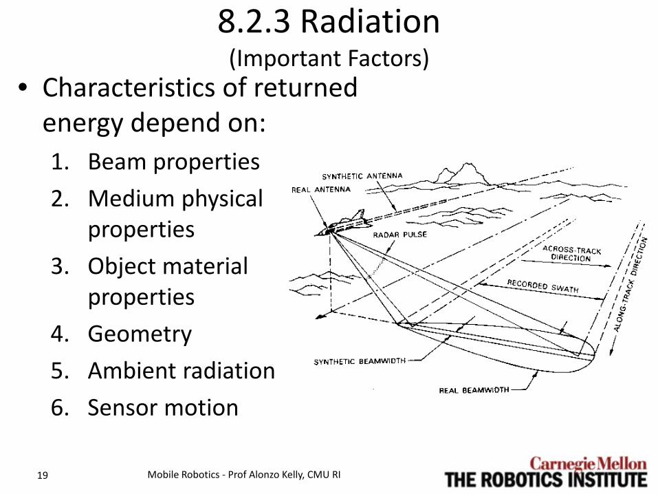
8.2.3 Radiation (Important Factors)
• Characteristics of returned energy depend on: 1. Beam properties 2. Medium physical
properties 3. Object material
properties 4. Geometry 5. Ambient radiation 6. Sensor motion
Mobile Robotics - Prof Alonzo Kelly, CMU RI 19

8.2.3.1 Beam and Antenna Properties • Angular resolution is a function of beamwidth. • Beamforming is accomplished by exploiting interference. • Beamwidth is angle where intensity drops to some percentage of
maximum. • Beam shape (and receiver sensitivity) is typically shown with a
directivity diagram like so:
Mobile Robotics - Prof Alonzo Kelly, CMU RI 20
aperture a
main lobe
side lobe
beamwidth 𝜃𝜃

8.2.3.1 Beam and Antenna Properties • Diffraction limit on resolution is: • Therefore, narrowing the beam requires:
– larger antennae – antenna motion, or – smaller wavelength
• BUT small wavelength increases attenuation.
Mobile Robotics - Prof Alonzo Kelly, CMU RI 21
θsin λ2a------=
aperture a
main lobe
side lobe
beamwidth 𝜃𝜃
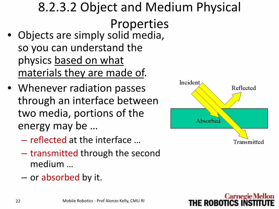
8.2.3.2 Object and Medium Physical Properties
• Objects are simply solid media, so you can understand the physics based on what materials they are made of.
• Whenever radiation passes through an interface between two media, portions of the energy may be … – reflected at the interface … – transmitted through the second
medium … – or absorbed by it.
Mobile Robotics - Prof Alonzo Kelly, CMU RI 22

8.2.3.2.1 Wave Speed • Electromagnetic • Sound
Mobile Robotics - Prof Alonzo Kelly, CMU RI 23

8.2.3.2.1 Wave Speed (Sound Speed)
• 5 X times faster in water than in air
• Very temperature dependent in air
Mobile Robotics - Prof Alonzo Kelly, CMU RI 24
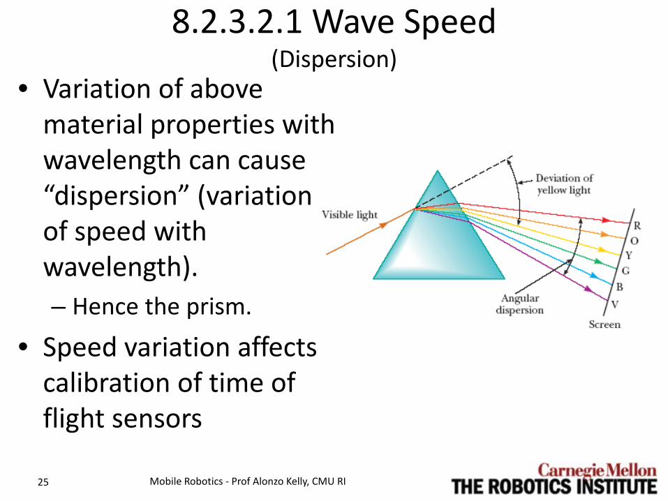
8.2.3.2.1 Wave Speed (Dispersion)
• Variation of above material properties with wavelength can cause “dispersion” (variation of speed with wavelength). – Hence the prism.
• Speed variation affects calibration of time of flight sensors
Mobile Robotics - Prof Alonzo Kelly, CMU RI 25

8.2.3.2.2 Attenuation • Attenuation = absorption +
scattering • Inherently its neither good
nor bad: – Sensor signal attenuated - bad – Ambient noise attenuated -
good
Mobile Robotics - Prof Alonzo Kelly, CMU RI 26
I
r

8.2.3.2.2 Attenuation (Absorption)
• Media tend to absorb fixed percentage per unit length (hence exponential behavior).
• For electromagnetic:
Mobile Robotics - Prof Alonzo Kelly, CMU RI 27
medium incident wave
transmitted wave

8.2.3.2.2 Attenuation (Sound Absorption)
• For sound, absorption: – increases with frequency in both H20, air – increases with relative humidity in air
• hence the fog horn
Mobile Robotics - Prof Alonzo Kelly, CMU RI 28
medium incident wave
transmitted wave

8.2.3.2.3 Transmission and Transparency • Absorptive properties indirectly affect how much energy is
transmitted after reflection. – Sometimes get no return if most of the incident energy is absorbed or
transmitted.
• Transparency – Some materials are transparent to radar, lidar - bad – Millimeter wave radar goes through underbrush - good – Some materials are strong sonar absorbers - bad
Mobile Robotics - Prof Alonzo Kelly, CMU RI 29
transmitter/ receiver
medium 2 medium 1

8.2.3.2.3 Transmission and Transparency (Transmission)
• Magnitude of the transmitted and reflected components of electromagnetic or sound energy is given by:
Mobile Robotics - Prof Alonzo Kelly, CMU RI 30
transmitter/ receiver
medium 2 medium 1

8.2.3.2.4 Reflection & Refraction • Non-normal incidence
can cause bending. • Depends on the relative
wave speed in the media involved.
• Laws apply to both EM and sound.
Mobile Robotics - Prof Alonzo Kelly, CMU RI 31
All rays lie in same plane
Snell’s Laws
medium 2 medium 1
incident
reflected
transmitted

8.2.3.3.1 Range from Source • By conservation, energy
has to “thin out” as it goes.
• Opposite is for a point source. Power at any radius is the same: – Ignoring attenuation
• Amplitude therefore falls off as 1/R.
Mobile Robotics - Prof Alonzo Kelly, CMU RI 32
“Intensity” is power passing through a surface per unit area
r P

8.2.3.3.2 Angle Off Symmetry Axis • For highly directive (focused) beams, returned
energy depends on where the sensor points • Blind spot is good or bad depending on whether
you want to detect objects off the beam axis
Mobile Robotics - Prof Alonzo Kelly, CMU RI 34
strong return
weak return
no return

8.2.3.3.3 Microscopic Surface Geometry • Geometry on the nanometer scale matters. • Waves may be reflected
– “specularly” = like a mirror – “diffusely” = spread out
• Real surfaces display both types of reflection to some degree.
Mobile Robotics - Prof Alonzo Kelly, CMU RI 35

8.2.3.3.3 Microscopic Surface Geometry • Specular reflection requires surface roughness
“roughly” less than the wavelength. • The transition from diffuse reflection to specular
takes place when this criterion is satisfied:
Mobile Robotics - Prof Alonzo Kelly, CMU RI 36
Rayleigh Criterion

8.2.3.3.3 Microscopic Surface Geometry (Three Effects Combined)
• Specular received power falls of as range squared,
• Diffuse received power falls off as range to the fourth power!
• Specular reflectors generate high power, but may not point it at the receiver.
Mobile Robotics - Prof Alonzo Kelly, CMU RI 38
Diffuse

8.2.3.3.3 Microscopic Surface Geometry (Effect on Exponent)
• Whether it is R4 or R2 depends only on the surface roughness.
• Next lets look at what affects the “Effective Area” of a surface patch.
Mobile Robotics - Prof Alonzo Kelly, CMU RI 39

8.2.3.3.4 Macroscopic (Object) Surface Geometry (Macroscopic Determines Cross Section)
• Integrated effect of both orientation and projected area gives cross section.
• Both objects below have same projected area and material properties.
• Each can be good or bad.
Mobile Robotics - Prof Alonzo Kelly, CMU RI 40
transmitter/ receiver
transmitter/ receiver
Low Cross Section High Cross Section

8.2.3.3.5 Macroscopic (Scene) Surface Geometry (Scene Geometry Transcends Cross Section)
• Object spatial relationships can dramatically enhance or suppress returns.
Mobile Robotics - Prof Alonzo Kelly, CMU RI 41
8.2.3.4 Sensor Motion • This is an issue for sonar mostly.
– Must wait for narrow beam to return (cannot rotate too fast )
– Must remember where you were when you sent the pulse (ladar too).
• Doppler shift is useful for velocity measurement.
Mobile Robotics - Prof Alonzo Kelly, CMU RI 42

8.2.3.5 Ambient Radiation • For active sensors, ambient effects can cause
problems: – random spurious readings – gradual degradations of model fidelity.
• BUT: Passive sensors (e.g. cameras) rely on it: – It must exist or be created (lights)
• Every modality cares about ambient radiation: – Sonar is sensitive to ambient noise. – IR lasers are sensitive to ambient illumination. – Radars sensitive to radio sources.
Mobile Robotics - Prof Alonzo Kelly, CMU RI 43
Here • This is test test
Mobile Robotics - Prof Alonzo Kelly, CMU RI 44

Outline • 8.2 Physics and Principles of Radiative Sensors
– 8.2.1 Radiative Sensors – 8.2.2 Techniques for Range Sensing – 8.2.3 Radiation – 8.2.4 Lenses, Filters, and Mirrors – Summary
Mobile Robotics - Prof Alonzo Kelly, CMU RI 45

8.2.4.1 Thin Lenses (Descartes Lensmaker’s Formula)
• Based on Snell’s law of Refraction. • Lenses both transmit, and refract
light. • Descartes: All rays emanating from P0
meet again at image point Pi. • When object is at infinity, we get the
distance to the image focal point Fi.
Mobile Robotics - Prof Alonzo Kelly, CMU RI 46
object point
image point
z
x
r t
air: refractive index 1
lens: refractive index n
center of curvature

8.2.4.1 Thin Lenses (focal length)
• Substitute second formula into first to get the thin lens formula (where f = xFi is called the focal length of the lens):
Mobile Robotics - Prof Alonzo Kelly, CMU RI 47
object point
image point
z
x
r t
air: refractive index 1
lens: refractive index n

8.2.4.1 Thin Lenses (Magnification)
• Define the magnification as ratio of image size to reality.
• Manipulating, we can derive the basic camera model.
Mobile Robotics - Prof Alonzo Kelly, CMU RI 48
z
x O
Q
R

8.2.4.1 Thin Lenses (Depth of Field)
• Objects at different ranges form images at different distances behind lens, so one or the other will be blurred.
• Depth of field is the motion of the image plane that produces a 1 pixel blur circle (on either side of perfect focus distance). – Larger depth of field means more of image is in focus. – Depth f field increases if you reduce aperture (and light entering lens).
Mobile Robotics - Prof Alonzo Kelly, CMU RI 49
z
x O
Q

8.2.4.3 Mirrors • These bend or distort the path of
a laser or the field of view of a camera – which can be useful.
• Omnicams can be constructed from a camera and a hyperbloidal mirror. – Great for seeing in all directions. – Great for distinguishing translation
from rotation in visual odometry.
Mobile Robotics - Prof Alonzo Kelly, CMU RI 50
mirror
pinhole lens
image plane

8.2.4.3 Mirrors (Omnicam Example)
Mobile Robotics - Prof Alonzo Kelly, CMU RI 51
Actual Image
Rectified Cylindrical Image

Outline • 8.2 Physics and Principles of Radiative Sensors
– 8.2.1 Radiative Sensors – 8.2.2 Techniques for Range Sensing – 8.2.3 Radiation – 8.2.4 Lenses, Filters, and Mirrors – Summary
Mobile Robotics - Prof Alonzo Kelly, CMU RI 56
Summary • Radiative sensors are the basic mechanism by
which mobile robots see what is around them. • Processing sensor data involves inverting models
of radiation, so the physics of radiation must be understood.
• Many effects including beam properties, medium and object physical properties, and geometry at all scales influence behavior of sensors.
• Proximity sensors are a simple and inexpensive means of ranging.
Mobile Robotics - Prof Alonzo Kelly, CMU RI 57


![[Unlocked] Chapter 8: Sensation and Perception](https://img.pdfslide.us/doc/110x75/61d6e504615e1108306c75f7/unlocked-chapter-8-sensation-and-perception.jpg)