Embed Size (px)
Citation preview

Chapter 7 : The Network Layer
By: Bhargavi Goswami, Sunshine Group of Institutions, Rajkot. Sub: FON, Email: [email protected] Page 1
Q. Network layer duties:
• Handling accounting for usage of network resources
• Devise and implement mechanisms of identifying each machine uniquely
• Implement connectionless or connection-oriented forwarding
• Multiplexing and de-multiplexing the transport layer and the data link layer jobs
• Following are the duties of network layer:
a) Routing
b) Accounting
c) Receive Service from DLL
d) Provide Service to Transport Layer
e) Global Machine-Level Addressing
f) Multiplexing and Demultiplexing Multiple Transport Layer Connections
g) Multiplexing and Demultiplexing Multiple Data Link Layer Connections
a) Routing
• Routing is
– to know about other routers
– where each of them is located
– which networks they are connected to
• Forwarding is
– finding out about one’s own neighboring routers
– forward a specified packet to its nearest neighbor to make it reach to a given destination
• Routing table contains information about nearest router for given destination
• Routing algorithms decide placement of routers
• Virtual circuit is mechanism used for connection oriented forwarding
• Datagrams are units of data sent in connectionless forwarding
Two different types of routing:
• Collection of networks organized by a single party is known as an autonomous system (AS).
• When packet needs to be routed within AS, internal routing methods are used. Internal routing
strategy is called “Link State Routing”. Eg. OSPF (Open Shortest Path First). Older technology was
“Distance Vector Routing”. Eg. RIP (Routing Information Protocol).
• When packet needs to be routed between different AS, we need external routing. Eg. BGP (Border
Gateway Protocol OR External Gateway Protocol.
• Exterior routing is across AS
– BGP (Border Gateway Protocol)
• Interior routing is within AS
– Distance Vector (eg. RIP)
– Link state (eg. OSPF)
– AODV
b) Accounting
• Network manages sessions, its accounting, keeps track of which user has sent how many packets.
• Payment is determined based on this accounting process.
• Accounting also helps in security, auditing and tracing process where IP falls short.
• Accounting helps in calculating how much bandwidth is used by which connection of ISP.
• Accounting is done by protocol named SNMP (Simple Network Management Protocol at
Application Layer.

Chapter 7 : The Network Layer
By: Bhargavi Goswami, Sunshine Group of Institutions, Rajkot. Sub: FON, Email: [email protected] Page 2
c) Receive Service from Data Link Layer:
• When IP Packet is constructed at network layer, it contains the source address as S and receiver’s
address as R.
• The data link layer frame is constructed at each hop is different as depicted in Figure given above.
• Network layer decides who the next recipient of this packet should be and then pass it on to the data
link layer.
• This structure is shown in next figure.

Chapter 7 : The Network Layer
By: Bhargavi Goswami, Sunshine Group of Institutions, Rajkot. Sub: FON, Email: [email protected] Page 3
d) Provide Service to Transport Layer:
• The network layer provides service to transport layer.
• The most important service is to accept packet to be sent to other end.
• The IP, upon receiving a packet, looks at a field called PROTOCOL to find out which transport layer
protocol it is trying to send information about.
• If PROTOCOL = 6; Pass content to TCP
• If PROTOCOL = 17; Pass content to UDP
e) Global Machine – Level Addressing:
• Biggest requirement is to identify machine globally.
• Eg. Email addresses are unique.
• How to achieve it? Best solution is IPv6. But, not practiced that much.
• Other options:
o Classful Addressing: Division is based on Size of Network.
Class A ( Accommodate 2 million nodes, First 1 byte for network, 3 byte for host).
Class B ( Accommodate 65533 nodes, First 2 byte for network, 2 byte for host) and
Class C ( Accommodate 254 nodes, First 3 byte for network, 1 byte for host).
o Dotted Decimal Notation:
32 bit long; i.e 4 bytes
Purely binary format addressing
Tough to remember.
o Classless Addressing:
IP Addresses are replaced by CIDR ( Classless Inter Domain Routing) by modern
routers.
Same 32 bit binary number is represented by byte boundary.
Even here, machine has unique address.
Here, slash notations are devised.
Eg. 128.10.0.0/24 means network address contains 24 bites.
In this structure, packet is passed to the router nearest to the network.
Such structure saves lot of routing table space.
See the next figures as examples.
o Aggregating Multiple Routing Entries:
• Normally R2 would have following 6 entries.
Network ID Next hop address Interface … (other fields)
11.1.0.0/16 R1 1
11.2.0.0/16 R1 1
11.3.0.0/16 R1 1
292.12.10.0/24 R3 2
292.12.12.0/24 R3 2
292.12.13.0/24 R3 2

Chapter 7 : The Network Layer
By: Bhargavi Goswami, Sunshine Group of Institutions, Rajkot. Sub: FON, Email: [email protected] Page 4
• As a solution, following table would save much of the space without affecting routing.
Network ID Next hop address Interface … (other fields)
11.*/16 R1 1
292.12.*/24 R3 2
o Unique Address Requirement:
• Problem: IP Address Conflict error may come if same address is used by multiple host.
• Solution: ISP can assign any unused address.
• Thus, sharing is possible but with condition that only one party is using that address at a
given point of time.
o NAT: Network Address Translation:
• Now, it is possible that one address is shared among a few nodes in the Internet using a
technology called NAT (Network Address Translation.
• Idea: Give each node an IP address that is not known in the Internet.
• Sender address is always modified to valid address by router connecting to Internet.
• Eg. Two nodes 10.1.1.2 and 10.1.1.2 will send packets together through NAT box or
NAT enabled Router with address 128.10.1.1.
• Advantage: Organization with fewer Internet address can accommodate multiple users
without taking Internet for each one of them.
• Almost all ISP today use NAT to cater to the needs of many broadband customers.
• Disadvantage: Still, NAT is a temporary solution. It cannot meet excessive requirement of
IP address for Internet connectivity.
o Real Solution: IPv6:
• IP next generation version 6.
• It is 128 bit address field.
• Better scheme for aggregation is available here.
• Two aggregation types supported: a) ISP-Wise and b) Location-wise.
• Internet is slowly moving towards all IPv6 case despite some interoperability issues.
f) Multiplexing and Demultiplexing Multiple Transport Layer Connections:
• It is possible to have TCP and UPD both together serving multiple applications.
• DNS and VoIP use UDP.
• FTP, Telnet and SMTP uses TCP.
• TCP and UDP are running independently with the help of Network Layer.
• Network Layer do this job using Multiplexing and Demultiplexing.
g) Multiplexing and Demultiplexing Data Link Layer Connections:
• Even Data link layer does this job to multiplex multiple network layer connections.
• Similarly, Transport layer does this for multiple Application data.
Q. Connection-Oriented Forwarding using Virtual Circuits:
• Steps involved in CO forwarding:
• 1) Find out a complete path to the other end
• 2) Informs the routers along the path and gets their confirmation
• 3) The service may be degraded or another path is tried if some router is not willing
• 4) Once the intermediate routers confirm to the requirement, resource allocation is done.
o (a) reserve resources
o (b) set the priorities
o (c) take a call on other services needed
o (d) reserve an amount of bandwidth
• 5) Now every connection is given Identifier by each router.
o Connection ID is provided

Chapter 7 : The Network Layer
By: Bhargavi Goswami, Sunshine Group of Institutions, Rajkot. Sub: FON, Email: [email protected] Page 5
o Independent of other routers
o No provision for a central authority
o The central authority needs to be consulted for every connection establishment
process
o If the central authority fails, no connection is possile
o Assigning the connection number locally is simple and effective
• 6) After every router accepts connection, unique number is assigned and same is expected
from receiver.
• Internet is not using Virtual Circuits currently, but, the method still exist and is known as
MPLS (Multi Protocol Label Switching).
• Flow label in IPV6 frame format does this job on behalf of MPLS.
Q. Connectionless Forwarding using Datagrams:
• Datagrams work on the concept of “dropped and forgotten”.
• It reaches the destination on its own, without no fixed path followed.
• Datagram based connectionless forwarding
• Advantages: Not wasteful, Autonomy and recovery supported, Better fault tolerance.
• Normal Path when no fault:
• A router out of order:
• A communication line out of order:

Chapter 7 : The Network Layer
By: Bhargavi Goswami, Sunshine Group of Institutions, Rajkot. Sub: FON, Email: [email protected] Page 6
Q. CO vs CL forwarding:
• Connection establishment: VC requires this phase, Datagram-based solutions do not
• Routing: Datagrams are checked and processed at every router while not in VC
• Speed of operation: more time to route datagrams
• Congestion control: Admission control vs routing around the congested path
• Addressing : Datagrams are designed to re-route
• Robustness : Datagrams are more robust when congestions are expected
• Quality of service: Connection-oriented service is better to provide QOS
Avoiding congested path while routing:
Suppose D is working:

Chapter 7 : The Network Layer
By: Bhargavi Goswami, Sunshine Group of Institutions, Rajkot. Sub: FON, Email: [email protected] Page 7
Now, D is not working:
B’s routing table before and after D stopped functioning:
Destination Next node Interface
A A 1
K A 1
I D 2
…… ….. …..
Q. Requirements of a good Routing Algorithms
• Packets continuously and forwards them to their destinations in minimum possible time.
• Impartial to all the nodes.
• Simple enough to be implemented
• Should not oscillate frequently to make packet forwarding erratic.
• Good path to receiver is recorded.
• Fault tolerance: Must continue functioning irrespective of nodes and links going up and down.
• Must not be bogged by increasing or decreasing number of nodes.
• Fast enough to reflect changes in network topology in real time.
• Speed is maintained.
• Other requirements:
– Dynamism and flexibility
– Performance
– Robustness
Dynamism and Flexibility:
• Must adopt to user requirements.
• High level algorithms need policy based implementation.
• Policies:
– Routing thru Russia is not allowed from US
– Routers of specific company routes data to it customers only
– Only after payment, data is transmitted.
• Algo must be flexible enough to adapt to changes.
Destination Next node Interface
A A 1
K A 1
I C 3
…… ….. …..

Chapter 7 : The Network Layer
By: Bhargavi Goswami, Sunshine Group of Institutions, Rajkot. Sub: FON, Email: [email protected] Page 8
• Changes in policies is frequent.
• Eg. Link state algo update after every minute to keep other routers informed about dynamic changes.
• When number of nodes increases, routers follow hierarchical routing.
• It stores only local address and 1 group address representing other group member’s addresses also.
Performance:
• Algorithms are implemented as algorithms only? No. Then? It is implemented as formula also.
• Routers do not follow algo or formulas only, it has clever tricks to do parallel job in fastest possible
way.
• Issues:
– Scale the size of network
• Network Grow in size, vary performance.
• Routers must catch up with increasing load on increasing nodes to the network.
– Quality of Service
• Maintenance of QoS is important factor.
• Data security standards must keep running despite of failures.
• Issues: Delay, fault tolerance, bandwidth variations, real time applications, Video On
Demand, Video Conferencing, etc
Performance: High Availability Solutions
• Modern routers have additional components to switch over when components breaks down.
• Multiple components are kept in routers just for improving fault tolerance.
• Routers are also equipped with spare routers which can take over when main routers fail for
improving fault tolerance.
• This helps user do not suffer from performance degradation.
• Functions of Routers
– Lookup
– Switching
– Queuing
Performance: Functions of Router
• Router maintains routing table having:
– Address Prefix
– Next router
– Interface
• One copy of routing port is kept at an input port.
• Based on routing table, output port is selected at router.
• Packet passes through switching logic, which results to switching right port.
• Taken care, no pending packets are kept at output port.
• Incoming packets are queued into output port.
• Once port is free, it starts travelling to higher layers.
• To improve performance, three operations are needed, Lookup, Switching and Queuing.
Lookup:
• Each incoming packet carry 32bit IP address which is to be matched with entries in routing table.
• Routing table contains only prefixes like 11*, 1010*, 100*, 10*...
• 11* and all others represent only those addresses starting with 11.
• Any address matching with 11* or 1010* will be forwarded to interface 1.
• Y addresses are truncated by prefixes instead of having complete addresses?
– Reduce Routing Table Size
– Limit the entries to Routing Table
• If we have 101011100, which matches with both 10* and 1010*, then which one should be selected?
• Rule: Consider “longest” match. i.e 1010 is selected.

Chapter 7 : The Network Layer
By: Bhargavi Goswami, Sunshine Group of Institutions, Rajkot. Sub: FON, Email: [email protected] Page 9
• See next figure to understand special customer who reserves his own router with ISP.
• This helps u send data to anyone connected to you. This is called host-specific entry.
• Goal: to see how fast it can lookup the entries and find out corresponding destination interface
considering longest match.
Functions of a router: Lookup
Address prefix Next router Interface …..
11* R1 1
1010* R1 1
10* R2 2
…
Why addresses should be truncated by prefixes?
• Router should divide the addresses in as many groups as the number of interfaces available.
• Easy management of the entries
Address prefixes help in routing:
Switching:
• Switching diverts the packet to output port connected to that interface.
• If router has n input and m output ports, router needs m x n interconnections, which is not possible.
• Solution? Crossbar Switches to avoid interconnections.
• High end routers use more connections, more hardware, so more speedy.
• This design plays major role in routing efficiency.
Router architecture:

Chapter 7 : The Network Layer
By: Bhargavi Goswami, Sunshine Group of Institutions, Rajkot. Sub: FON, Email: [email protected] Page 10
Queuing:
• Worst Case: when all the input ports are sending data to single output port.
• Solution: Output port must be able to work as 100 pkt/sec to handle total load efficiently.
• When output port is less capable then input load, there is bound to pkts which cannot be forwarded
as and when they arrive.
• Solution: Output port has buffers which act as a queue for incoming packets.
• Incoming ports are stored at buffer until the port becomes free.
• Eg: ICMP (Internet Control & Message Protocol)
• SNMP (Simple Network Management Protocol).
• A good routing algo is one which can help manage all these operations together in most optimistic
way.
• An ideal algorithm is one which does not have any of lookup, queuing and switching.
Robustness:
• Robustness: A good algorithm keeps running despite the nodes or links going down or coming up.
• Must converge in presence of large network to steady state.
• Must not oscillate from one route to another.
• See fig next;
• One of these two path has to be selected. i.e A’K and C’J.
• One of these two paths must be selected as best route.
• Now, moving to optimum path one packet starts from K’ and goes to A.
• But while moving forward, A observed that D no longer exist.
• Design: Use both, path while balancing load.
• There is no algorithm that performs load balancing.
• Now, Packet traverse : K’ – I’ – J’ – C’ – J being selected as shortest path.
• But, network being dynamic, packet changes its path k’ – I’ – A’ – K.
• If this happens continuously , poor packet will only move back and forth and never get out of its
current network.
• This design uses both, Path and load balancing.
• However, load balancing is still an issue.

Chapter 7 : The Network Layer
By: Bhargavi Goswami, Sunshine Group of Institutions, Rajkot. Sub: FON, Email: [email protected] Page 11
• Unstable algorithms are not welcomed by network keeping best path priority less than stability.
• If it oscillates wildly, packets might take much longer time and may be not reached to destination.
• Robustness also depends on algo’s behaviour in link or node failure.
• Connectionless model of internet is so efficient for vulnerable networks that despite network or link
failure, packet forwarding does take place.
• Connectionless is considered fairly efficient.
• Robustness can be increased by taking into account new or recovered nodes despite failure.
• Periodically update their status and broadcasting the same to other nodes also avoid oscillation
issues.
Q. Issues in router’s performance:
• A router must scale up to the size of the network attached to it
• Quality of service
– Delay
– delay tolerance
– bandwidth, particularly for real-time applications
– Fault tolerance
– High availability
Q. Comparison of Virtual-Circuit and Datagram Subnets
Q. Distance Vector Routing Algorithm:
• So far we have studied Static Routing Algorithms.
• But practically dynamic Routing Algorithms are used.
• Following two are Dynamic Routing Algorithms:
– 1. Distance Vector Routing Algorithm.
– 2. Link State Routing Algorithm.
Distance Vector Routing Algorithm: • At each step within a router:

Chapter 7 : The Network Layer
By: Bhargavi Goswami, Sunshine Group of Institutions, Rajkot. Sub: FON, Email: [email protected] Page 12
– Get routing tables from neighbours
– Compute distance to neighbours
– Compute new routing table
1. Router transmits its distance vector to each of its neighbors.
2. Each router receives and saves the most recently received distance vector from each of its neighbors.
3. A router recalculates its distance vector when:
a. It receives a distance vector from a neighbor containing different information than before.
b. It discovers that a link to a neighbor has gone down (i.e., a topology change).
• The DV calculation is based on minimizing the cost to each destination.
• The distance vector routing algorithm is sometimes called by other names, the distributed Bellman-
Ford routing algorithm and the Ford-Fulkerson algorithm.
The subnet for routing and J is the sender:
Partial Routing table for J:
Network Next router Interface
E G 1
A I 2
B I 2
X I 2
V G 1
W G 1
Q C 3
….. ….. …..

Chapter 7 : The Network Layer
By: Bhargavi Goswami, Sunshine Group of Institutions, Rajkot. Sub: FON, Email: [email protected] Page 13
Constructing routing tables Estimated delay from I:
Network Next router Delay
A D 2
B D 2
K K 1
O O 1
X P 2
U P 2
V P 3
….. ….. …..
Constructing routing tables Estimated delay from G
Network Next router Delay
E E 1
A J 4
B E 4
X L 4
F F 1
H M 2
M M 1
….. ….. …..
Constructing routing tables Estimated delay from C
Network Next router Delay
E E 1
A J 4
B E 4
X L 4
F F 1
H M 2
M M 1
….. ….. …..

Chapter 7 : The Network Layer
By: Bhargavi Goswami, Sunshine Group of Institutions, Rajkot. Sub: FON, Email: [email protected] Page 14
Constructing routing tables, another Example
Constructing routing tables, another Example
Estimated delay from B Estimated delay from D
Network Next router Delay Network Next router Delay
A A 3 A A 5
D D 6 B B 6
K A 10 K A 12
H D 8 H H 2
J D 12 J H 6
G D 11 G G 5
Constructing routing tables: constructing routing table from two of the neighbor’s inputs
E’s Routing table
Network Next router Delay
A B 8
B B 5
D D 4
K B 15
H D 6
G D 9
J D 10
Drawback: Count to Infinity Problem:
• Drawback of Distance Vector Routing:
– Count to Infinity Problem:
• It reacts rapidly to good news,
• But, leisurely to bad news.

Chapter 7 : The Network Layer
By: Bhargavi Goswami, Sunshine Group of Institutions, Rajkot. Sub: FON, Email: [email protected] Page 15
• Updates value fast when neighbor is down, but not when neighbor is again up. How?
• Lie to neighbour about distance if routing via neighbour
• The core of the problem is that when A tells B that it has a path to D, B has no way of
knowing whether it itself(B) is on the path? This is how problem is created.
– It does not take bandwidth into account.
– Take too long to converge changes in one node to all other nodes.
• Solution?
• Split Horizon Hack. Lets see what it is.
Count to infinity problem: E’s routing table when D goes down:
Network Next router Delay
A B 8
B B 5
D B 9
K B 15
H B 13
G B 16
J B 17
Count to Infinity Problem, Another example:
Count to infinity: C’s and B’s routing tables before D is down
Network Next router Delay
A B 4
B B 2
D D 2
Network Next router Delay
A A 2
C C 2
D C 4
A’s routing table and C’s modified routing table when D is down

Chapter 7 : The Network Layer
By: Bhargavi Goswami, Sunshine Group of Institutions, Rajkot. Sub: FON, Email: [email protected] Page 16
How C’s routing table is further modified:
Solution by lying: SPLIT HORIZON HACK
• Rule: If B ask A, distance from A to D, and if B lies in the path, A should reply to B that A has path
to D equal to infinite.
• This would avoid trapping of B into the loop of infinity.
• The best remedy is not to enter into Count to Infinity problem.
• This is called Split Horizon Hack.
B’s routing table
Network Next router Delay
A A 2
C C 2
D C infinity
Q. Link State Routing Algorithm:
Each router must do the following:
1. Discover its neighbors, learn their network address.
2. Measure the delay or cost to each of its neighbors.
3. Construct a packet telling all it has just learned.
4. Send this packet to all other routers.
5. Compute the shortest path to every other router.
A complete topology is developed. Then Dijkstra’s Algorithm can be used to compute the shortest path.
Following 5 steps are followed to implement it.
1. Learning about the Neighbors
2. Measuring Line Cost.
3. Building Link State Packets.
4. Distributing the Link State Packets.
5. Computing the New Routes.
Step1: Learning about the Neighbours:
Upon boot of router,
o Send HELLO packet on each point-to-point line
o Routers are supposed to send reply with a globally unique name
Step 2: Measuring the Line Cost:
Measure round-trip delay using ECHO Packet and wait for its reply
Take load into account? Yes. Arguments both ways: when choice is given to router having same
number of hops from S to D.
o Yes! preference for unloaded line as shortest path.
o No! where oscillations are possible.
Better Solution? Distribute Load over multiple lines.
A subnet in which the East and West parts are connected by two lines:

Chapter 7 : The Network Layer
By: Bhargavi Goswami, Sunshine Group of Institutions, Rajkot. Sub: FON, Email: [email protected] Page 17
Step 3: Building Link State Packets:
Packet containing:
o Identity of sender
o Sequence number + age
o For each neighbour:
o name + distance
When to build the link state packets?
o Periodically
o when significant events occur
See next figure.
Step 4: Distributing Link State Packets:
Distributing link state packets
– Trickiest part of algorithm
• Arrival time for packets different
• How to keep consistent routing tables?
– Basic algorithm
• Flooding +
• Sequence number (in each packet) to limit duplicates.
– Manageable problems
• Wrap around of sequence numbers results to wrong data. Solution? Use 32 bit sequence
number.
• Wrong sequence number used in case of :
– lost in case of crash
– Corrupted data transmitted.
– Solution? include the age of each packet after the sequence number and decrement it once per
second. When the age hits zero, the information from that router is discarded.
– duplicates are discarded
– Old packets are thrown out

Chapter 7 : The Network Layer
By: Bhargavi Goswami, Sunshine Group of Institutions, Rajkot. Sub: FON, Email: [email protected] Page 18
Step 5: Computing new routes: – With a full set of link state packets, a router can:
• Construct the entire subnet graph
• Run Dijkstra’s algorithm to compute the shortest path to each destination
– Problems for large subnets
• Memory to store data
• Compute time for developing these tables.
– Usage:
– IS-IS protocol (Intermediate System, Intermediate System)
• Designed for DECnet(digital equipment corporation network protocol suite), adopted by
ISO(international standardization organization), used still in internet.
• Supports multiple network layer protocols
– OSPF(Open Shortest Path First) protocol used in Internet : Common features:
• Self-stabilizing method of flooding link state updates
• Concept of a designated router on a LAN
• Method of computing and supporting path splitting and multiple metrics.
• Useful in Multi Protocol Environment.
• Collecting Information from other routers and estimating the AS(Autonomous System) topology
• Finding neighbours and delay
• Sequence number and Age fields
• Routing table construction
Header
Node Delay
E 5
D 6
A 3
Link state packets from all neighbours:
From B From A From K
Node Delay Node Delay Node Delay
E 5 B 3 A 7
D 6 D 5 H 8
A 3 K 7

Chapter 7 : The Network Layer
By: Bhargavi Goswami, Sunshine Group of Institutions, Rajkot. Sub: FON, Email: [email protected] Page 19
From D From G From H From J
Node Delay Node Delay Node Delay Node Delay
B 6 D 5 K 8 G 3
A 5 J 3 D 2 H 4
H 2 J 4
G 5
The graph constructed from all the packets:
E’s routing table:
Network Next router Delay
A B 8
B B 5
D D 4
K B 15
H D 6
G D 9
J D 10
The issue when LAN is a part

Chapter 7 : The Network Layer
By: Bhargavi Goswami, Sunshine Group of Institutions, Rajkot. Sub: FON, Email: [email protected] Page 20
Solution: depict LAN as a node
Q. Optimality Principle
• Optimality Principle: states that if router J is on the optimal path from router I to router K, then the
optimal path from J to K also falls along the same route.
• Set of optimal routes from all sources to a given destination form a tree rooted at the destination.
Such a tree is called a sink tree. See next figure.
• Note that a sink tree is not necessarily unique; other trees with the same path lengths may exist.
• Since a sink tree is indeed a tree, it does not contain any loops, so each packet will be delivered
within a finite and bounded number of hops.
• Optimality principle and the sink tree provide a benchmark against which other routing algorithms
can be measured.
• The goal of all routing algorithms is to discover and use the sink trees for all routers.

Chapter 7 : The Network Layer
By: Bhargavi Goswami, Sunshine Group of Institutions, Rajkot. Sub: FON, Email: [email protected] Page 21
Q. Differentiate between LINK STATE and DISTANCE VECTOR Routing Algorithm:
Sq.No. Link State Distance Vector
1 link states algorithm is an algorithm using
global information
the distance vector algorithm is iterative,
asynchronous, and distributed
2 each node talks with all other nodes, but
tell them only the cost of it's directly
comparison of some of their attribute
each node talks to only its directly connected
neighbors, but provides its neighbor with least cost
estimates from itself to all the nodes.
3 Message complexity: With link state, every
node has to keep the information about the
cost of each link within the network.
Message complexity: with distance vector
algorithm, message is exchanged between two hosts
which are directly connected to each other.
4 Every times, if any of the link cost is
changed, all the nodes are updated.
The change of cost in the link which belongs to the
least cost path for one of the nodes, the DV
algorithm will update the new value. But if the
change doesn't belong to the least cost part between
2 hosts, there will no updating.
5 Speed of convergence: can converge faster
in comparison of later.
Speed of convergence: can converge slowly and
have routing loops while the algorithm is
converging.
6 Such probability is less. DV algorithm also suffers from the count to infinity
problem.
7 Robustness: For LS, when a router is down,
it can broadcast a wrong cost for the closest
one. LS node is computing for its own
forwarding table and other node do the
calculation for themselves. Better than DV.
Robustness: DV, the wrong least cost path can be
passed to more than one or all of the node so the
wrong calculation will be process in the entire net
work. This problem of DV is much worse than LS
algorithm.

Chapter 7 : The Network Layer
By: Bhargavi Goswami, Sunshine Group of Institutions, Rajkot. Sub: FON, Email: [email protected] Page 22
Q. Explain characteristics of MANET routing.
It is characterized with following prominent characteristics.
o No special-purpose routers
o No fixed topology
o Best path assumptions are done independently.
o Power requirements may be the issue. If A – B – C, and A is communicating to C through B, if power
scarcity is observed in B, B may not forward packets from A to C.
o Security issues exist in MANETs.
Example of MANET is AODV protocol.
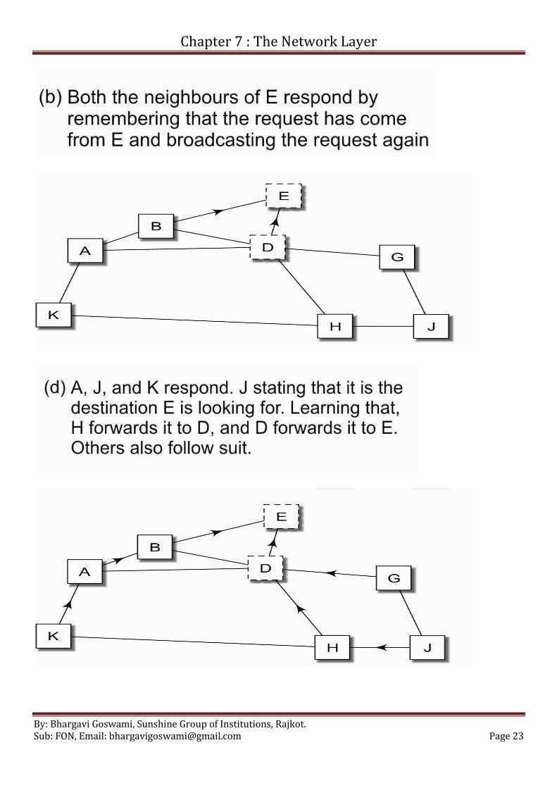
Q. Explain AODV Protocol in details.
AODV: Ad-hoc On-demand Distance Vector Routing Algorithm used with MANETs.
More reactive and not pro-active routing algorithm.
Is a Distance Vector variant.
When nodes want to send data, it runs route discovery process.
For the figure given below, see how the route discovery is made represented step by step from a) to e)
Chapter 7 : The Network Layer
By: Bhargavi Goswami, Sunshine Group of Institutions, Rajkot. Sub: FON, Email: [email protected] Page 23

Chapter 7 : The Network Layer
By: Bhargavi Goswami, Sunshine Group of Institutions, Rajkot. Sub: FON, Email: [email protected] Page 24

Chapter 7 : The Network Layer
By: Bhargavi Goswami, Sunshine Group of Institutions, Rajkot. Sub: FON, Email: [email protected] Page 25
Two main operations performed by AODV are:
o Route Discovery
o Route Maintenance
Route Discovery Operation:
AODV: Format of a Route-Request packet
Source ID Request ID Destination
ID
Source
sequence no.
Destination
sequence no.
Hop count Time-
to-Live
Source ID: Source Address
Destination ID: Destination Address
Request ID: The request made is identified with this.
Source and Destination Sq. No: Sequence number of Source and Destinations
Hope Count: Intermediate nodes between the sender and receiver.
Time To Live: Indicates the age field for the frame. If the node goes down before frame reaches the destination,
may result to addition of network load. To avoid this, TTL field discards the packet once it reaches its limit.
Route Maintenance:
Issue here is, how to find, when the node left the network while moving.
Suppose B in previous figure gets disconnected and D comes to know about that, then D must inform these two
nodes. i.e G and H.
They are known as active neighbors for a given destination.
So, G and H upon receipt, both of them repeat the process for their active neighbours.
See the D’s Table for Routing.
Route Maintenance: D’s Current routing table
Destination Next hop Distance Active neighbours …
B B 1 G, H …
E E 1 H …
A A 1 G …
K A 2 G, E …
H H 1 A …
G G 1 B …
J H 2 E …
AODV does not use power as one of the parameters to route, however its variants use this parameter.

Chapter 7 : The Network Layer
By: Bhargavi Goswami, Sunshine Group of Institutions, Rajkot. Sub: FON, Email: [email protected] Page 26
Q. What is flooding? Flooding algorithm: every incoming packet is sent out on every outgoing line except the one it arrived on.
Flooding obviously generates vast numbers of duplicate packets, in fact, an infinite number unless some measures
are taken to damp the process.
One such measure is to have a hop counter contained in the header of each packet, which is decremented at each
hop, with the packet being discarded when the counter reaches zero.
An alternative technique for damming the flood is to keep track of which packets have been flooded, to avoid
sending them out a second time.
A variation of flooding that is slightly more practical is selective flooding. In this algorithm the routers do not
send every incoming packet out on every line, only on those lines that are going approximately in the right
direction.
Applications of flooding algorithm:
1. military applications
2. distributed database applications
3. wireless networks
4. as a metric against which other routing algorithms can be compared
Flooding always chooses the shortest path because it chooses every possible path in parallel.
Q. Explain Border Gateway Protocol (BGP) in detail.
Is an exterior protocol.
Helps routing between different autonomous systems (AS).
Here we also need to keep an eye on policies of different AS for routing as it works across the borders.
Routing Policies:
o When a packet has US army as sender, should not forward it through a path that touches Afghanistan.
o Packet destined for an intelligent agency in India should not be forwarded to a path that passes through
Pakistan.
o Let all packets pass through my AS, but not Microsoft. (Sender is from Sun or IBM)
o A telephone company willing to forward packets of its own customers and not others.
o A service provider willing to forward packets of whoever pays for the services rendered.
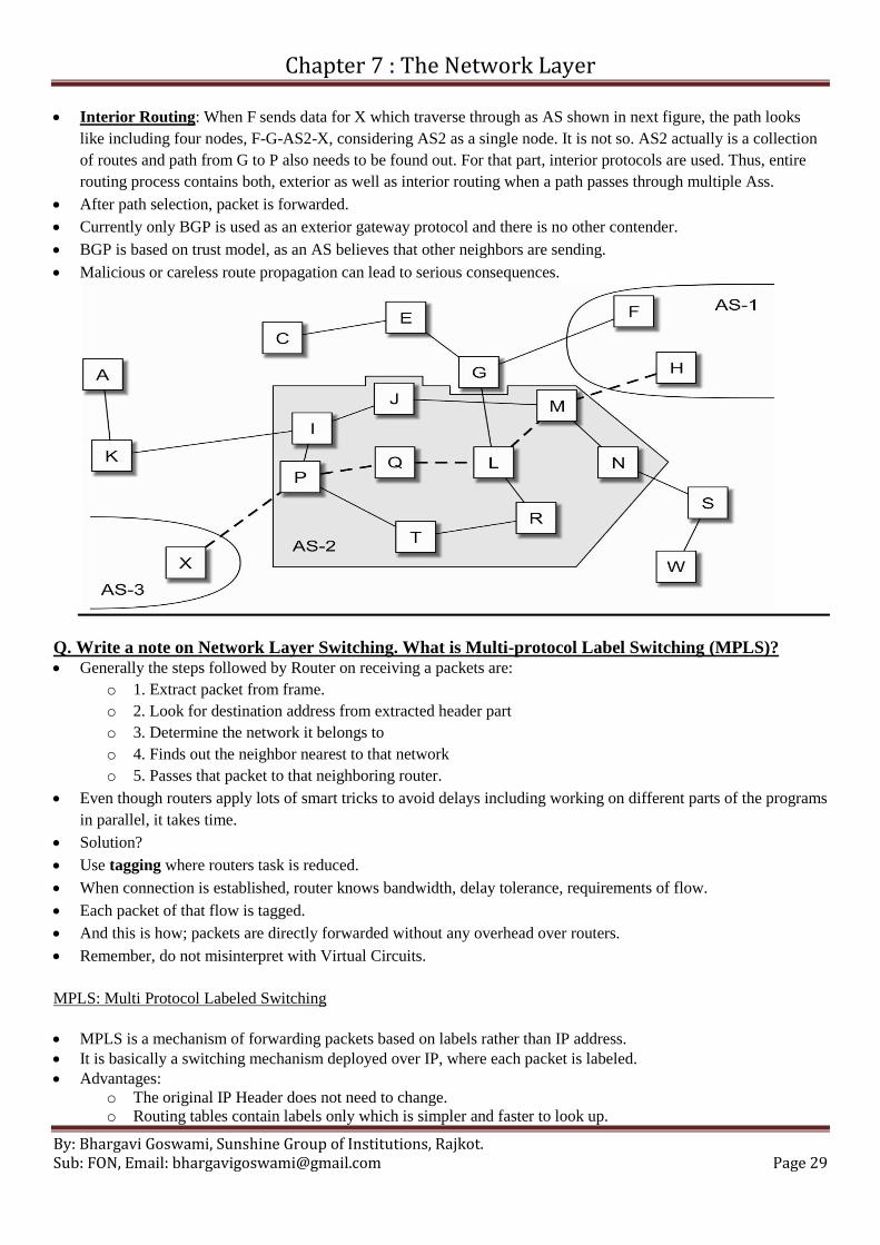
Categorization of AS:
o First: Only 1 Connection to rest of network (like leaf node). In next figure C and F are first type.
o Second: Non Leaf nodes in the network, not willing to provide service of forwarding packets to other
nodes. In next figure, G and H.
o Third: Non Leaf Nodes in the network that is willing to provide service of forwarding packets to other
nodes. In next figure, D, A, B, E.

Chapter 7 : The Network Layer
By: Bhargavi Goswami, Sunshine Group of Institutions, Rajkot. Sub: FON, Email: [email protected] Page 27
Stub Network: There are nodes that contain single link to the network. This node cannot be used for traffic transit.
Such a network is known as Stub Network. It’s a customer’s AS which is connected to Internet via single
communication line to ISP.
The biggest difference between BGP and DV protocols is the storage of routing information. Storage of BGP is
much more than DV.
Path Vector Routing: You might have two internet connections from Airtel and Reliance, so are connected to
both, but you will not prefer to relay traffic between these two AS. BGP, instead of getting information about only
next hop from all the information, it gets complete information of the entire path to B. This process is called path
vector routing.
No count to infinity: When router finds a path containing same node twice, it understands that the route contains
loop and avoids that path. So no chance of count to infinity in BGP.
Complexity: BGP is far more complex protocol than any other protocol. There are levels as well as hierarchy.
Sometimes they have more than one connection to a single destination to enable load balancing and/ or fault
tolerance.
Impact of Business Relationship: Business relationships are based on contracts and when contracts are terminated
or revised, the connections are removed or connection weights are revised.
Why Not Link State Routing Algorithm here?
o Sending information to 40,000 from single AS is a big task, can’t be done by LS.
o Requires extremely high bandwidth, can’t be handled by LS.
o Storing information will also consume lot of memory, which is not done by LS.
BGP Operations:
o Step 1: Router Discovery, Path and all the alternative path discovery.
o Step 2: Computation of Shortest Route.
Every AS is given unique ID. Eg. AT&T has 7018 and Reliance has 32400.
See next figure, AS-4 has two different paths to AS-11 (11-6-5-4 and 11-6-7-4) and both of them contend for the
best path. This is first stage in BGP process.
Second stage includes comparison between two alternatives available.
Following factors are consider for stage 2, i.e computing best alternative among all the path available.
Load Preference: Eg. Heavily loaded path like the link though R&D department are avoided.
Avoiding false alarms: Some route announcements seem suspicious or a mistake.
Check the willingness to be intermediate nodes. If they are not willing to forward, avoid such intermediate nodes.
Hot Potato: Suppose, the path takes longer but spends less time in AS, while another path is shorter but spends
more time in AS. Second path is preferred as AS doesn’t want to go through heavy traffic. Eg. See next figure. If
we want to go from H to X, we can go with M-L-Q-P-X but we prefer going though M-L-G-E-C-K-X. Means,
here, everybody is avoiding heavy traffic lines (hot potato in hands). That’s why it is called Hot Potato.

Chapter 7 : The Network Layer
By: Bhargavi Goswami, Sunshine Group of Institutions, Rajkot. Sub: FON, Email: [email protected] Page 28
Chapter 7 : The Network Layer
By: Bhargavi Goswami, Sunshine Group of Institutions, Rajkot. Sub: FON, Email: [email protected] Page 29
Interior Routing: When F sends data for X which traverse through as AS shown in next figure, the path looks
like including four nodes, F-G-AS2-X, considering AS2 as a single node. It is not so. AS2 actually is a collection
of routes and path from G to P also needs to be found out. For that part, interior protocols are used. Thus, entire
routing process contains both, exterior as well as interior routing when a path passes through multiple Ass.
After path selection, packet is forwarded.
Currently only BGP is used as an exterior gateway protocol and there is no other contender.
BGP is based on trust model, as an AS believes that other neighbors are sending.
Malicious or careless route propagation can lead to serious consequences.
Q. Write a note on Network Layer Switching. What is Multi-protocol Label Switching (MPLS)?
Generally the steps followed by Router on receiving a packets are:
o 1. Extract packet from frame.
o 2. Look for destination address from extracted header part
o 3. Determine the network it belongs to
o 4. Finds out the neighbor nearest to that network
o 5. Passes that packet to that neighboring router.
Even though routers apply lots of smart tricks to avoid delays including working on different parts of the programs
in parallel, it takes time.
Solution?
Use tagging where routers task is reduced.
When connection is established, router knows bandwidth, delay tolerance, requirements of flow.
Each packet of that flow is tagged.
And this is how; packets are directly forwarded without any overhead over routers.
Remember, do not misinterpret with Virtual Circuits.
MPLS: Multi Protocol Labeled Switching
MPLS is a mechanism of forwarding packets based on labels rather than IP address.
It is basically a switching mechanism deployed over IP, where each packet is labeled.
Advantages:
o The original IP Header does not need to change.
o Routing tables contain labels only which is simpler and faster to look up.

Chapter 7 : The Network Layer
By: Bhargavi Goswami, Sunshine Group of Institutions, Rajkot. Sub: FON, Email: [email protected] Page 30
o Tags are much easier to manage than the large number of IP address.
o Different connections can be identified by their tags.
o Network Layer IP becomes immaterial. (IP Header)
o Router functions become independent of network layer protocol
o It is possible to have multiple labels pasted on a packet, one over the other. This is important when
hierarchy of networks is needed.
o Forwarding process becomes faster as smaller labels are easier to index.
o MPLS is usually designed to label the packets on the basis of not only Layer-3 (IP) but also Layer-4 (TCP
or UDP) and sometimes Layer-5 (SMTP, FTP, HTTP) protocols.
See the following example of hierarchical networking with ISP1, ISP-2, ISP-3 and ISP4.
Packet at node Tags added to the packet
Before entering the network Packet
D Packet, ISP-1 Tag
I Packet, ISP-1 Tag, ISP-2 Tag
P Packet, ISP-1 Tag, ISP-2 Tag
Q Packet, ISP-1 Tag, ISP-3 Tag
L Packet, ISP-1 Tag, ISP-3 Tag, ISP-4 Tag
M Packet, ISP-1 Tag, ISP-3 Tag, ISP-4 Tag
W Packet, ISP-1 Tag
After leaving the network Packet
MPLS Enabled Routers: An MPLS enabled router understands the existence of MPLS tags and can route them
accordingly.
Let’s see the frame format for the same.
MPLS Frame Format:
The MPLS header is attached above IP so, it doesn’t alter content of IP header, nor depends on IP header content.
MPLS header sits below PPP. So, MPLS is used with Ethernet.
MPLS header is of 4 bytes, 32 bit long with largest part of Label field, 20 bits.
20 bits can have 2 to the power 20 (220
) unique labels can be assigned.
QOS field indicates quality of service needed by a specific packet.
TTL stands for Time to Live. Sender initializes it which is decremented at every router it reaches.
S field holds 1 when only one tag is used. And if tags are more than one, S field has 0.

Chapter 7 : The Network Layer
By: Bhargavi Goswami, Sunshine Group of Institutions, Rajkot. Sub: FON, Email: [email protected] Page 31
Only disadvantage is : Complex mechanism of MPLS router label assignment procedure.
Q. Congestion:
• Means Traffic Jam.
• Incoming Pkt > Outgoing Pkt
• Result: Buffer frames at router
• If even more pkts, router is unable to handle, so, start DROPPING pkts.
• This is known as Congestion.
• Reason, Busty unpredictable traffic, slow processing router.
• Result, bottleneck links, buffers overrun, difficult to control the process, outgoing lines cannot hold
the load over network, so fail to deliver.
• Congestion feeds itself, means, one router when gets congested, neighbouring routers will be
congested soon.
• Y? being sharing the load of congested router.
• Also, retransmission is induced by pkt drops, inducing more congestion.
• Solution? Congestion Control Mechanism.
Congestion Control:
• Explicit control
– Admission control
– Prevention of congested routes
• Implicit control
– RED
– Jitter Control
• Congestion Control: Methods deployed to combat congestion and reduce the effect of congestion are
know as congestion control.
• Strategies:
– Detection
• Flexible, less control over network, less stability
• Based on feedback mechanism, ACK, Chock Packets
• Datagram
• Connectionless
• Wait for congestion to happen and then solve it
– Preventions
• need good design and control, more stability
• Virtual Circuits

Chapter 7 : The Network Layer
By: Bhargavi Goswami, Sunshine Group of Institutions, Rajkot. Sub: FON, Email: [email protected] Page 32
• Connection Oriented
• Prevention measures are taken before congestion occurs.
Feedback: Explicit or Implicit
• Explicit Feedback
– ECN: Explicit Congestion Notification field in TCP and IP header indicating congestion.
– Turned on indicating Possibility of Congestion
– ICMP: Internet Control Message Protocol
• Implicit Feedback
– Older TCP implementation had no field to indicate congestion.
– Retransmission, RTT and Dropping events indicate congestion.
• TCP is ideal case of adaptive congestion control.
• Network layer implement congestion control, bcoz, has hop to hop control.
• Transport layer does flow control, get direct feedback from receiver the data rate.
• But controlling of congestion is done better by network layer only.
• Network layer help recovering from congestion as it does routing and forwarding.
• IP does small congestion control.
• IP just sends packets and forgets.
• However, TCP monitor the communication and checks for delays and retransmission.
• UDP doesn’t implement congestion control.
Congestion Control Algorithms:
• Admission Control
• Prevention of Congested Routes
• Global Synchronization
• RED, Random Early Detection
• Jitter Control
Admission Control:
• Prevention Type
• Algorithm:
a) Sender request with bandwidth requirement and CPU time needed
b) All other routers agree looking at current load
c) If requirement can’t be fulfilled, request is dropped by routers.
• Observed in Telephone networks
• Connection building takes time, but once connected, quality is maintained.
• It restricts user from connecting to network, so not used by internet.
• Internet uses Admission control for real time traffic.
• Applied at Application Layer in internet.
• Eg, CAC: Call Admission Control, used by VoIP traffic, prevents oversubscription, used with SIP.
• SIP: Session Initiation Protocol.
Prevention of Congested Routers:
• Before establishing connection, selection of path determines the congested lines and avoid them
during selection.
• No new connection establishment over the congested node.
• Better Solution than admission control
• Algorithm:
– Connection establishment reserves resources
– Once connection is established, sender send bandwidth, cpu time and store requirements
– Load balancing is checked and path is chosen
• Only drawback, adds overhead.
• Multiplexing can accommodate 3x calls.
Chapter 7 : The Network Layer
By: Bhargavi Goswami, Sunshine Group of Institutions, Rajkot. Sub: FON, Email: [email protected] Page 33
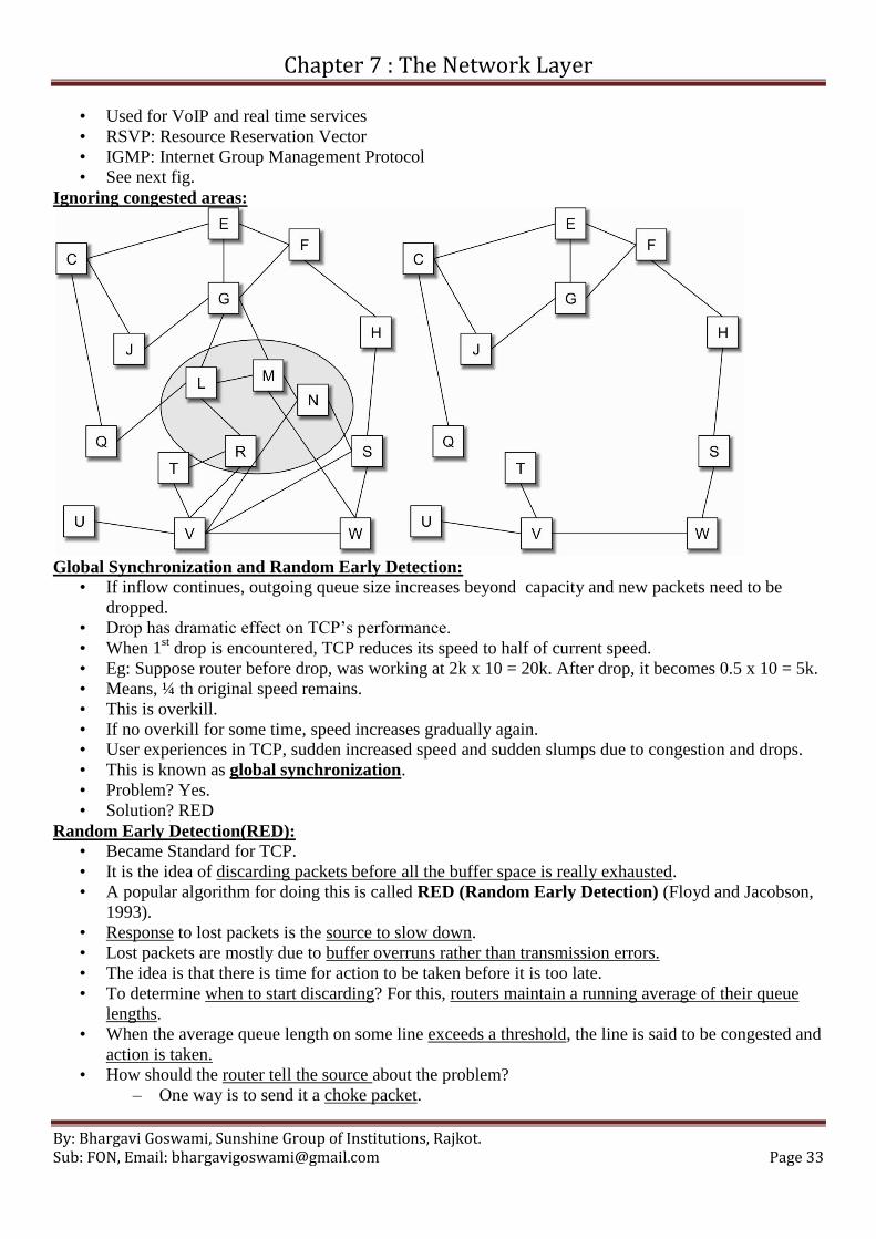
• Used for VoIP and real time services
• RSVP: Resource Reservation Vector
• IGMP: Internet Group Management Protocol
• See next fig.
Ignoring congested areas:
Global Synchronization and Random Early Detection:
• If inflow continues, outgoing queue size increases beyond capacity and new packets need to be
dropped.
• Drop has dramatic effect on TCP’s performance.
• When 1st drop is encountered, TCP reduces its speed to half of current speed.
• Eg: Suppose router before drop, was working at 2k x 10 = 20k. After drop, it becomes 0.5 x 10 = 5k.
• Means, ¼ th original speed remains.
• This is overkill.
• If no overkill for some time, speed increases gradually again.
• User experiences in TCP, sudden increased speed and sudden slumps due to congestion and drops.
• This is known as global synchronization.
• Problem? Yes.
• Solution? RED
Random Early Detection(RED):
• Became Standard for TCP.
• It is the idea of discarding packets before all the buffer space is really exhausted.
• A popular algorithm for doing this is called RED (Random Early Detection) (Floyd and Jacobson,
1993).
• Response to lost packets is the source to slow down.
• Lost packets are mostly due to buffer overruns rather than transmission errors.
• The idea is that there is time for action to be taken before it is too late.
• To determine when to start discarding? For this, routers maintain a running average of their queue
lengths.
• When the average queue length on some line exceeds a threshold, the line is said to be congested and
action is taken.
• How should the router tell the source about the problem?
– One way is to send it a choke packet.

Chapter 7 : The Network Layer
By: Bhargavi Goswami, Sunshine Group of Institutions, Rajkot. Sub: FON, Email: [email protected] Page 34
– Other option? Just discard the selected packet and don’t report even.
– Source will eventually notice lack of Ack and takes action.
– Thus, slowing down instead of trying harder.
Jitter Control:
• Rule: Pkt must not fall behind its predecessor, it should not jump ahead of its successor.
• Eg: in Video conferencing, its imp that different pkts are not delayed differently, otherwise picture
quality deteriorates.
• Jitter: Variation in inter-packet intervals is known as Jitter and Jitter control is must for each
multimedia application.
• Not much imp for Normal Data but, is must for Multimedia applications.
• Jitter Control: Two methods
– Service Type: IP field service type tells us the type of data, i.e real time or non real time data.
Routers can’t differentiate this difference of data types.
– Differentiated Service: Implemented in IP. Sets a number based on urgency of data delivery.
But, all users think their data is urgent. So Differentiated Service Indicator decides type of
service needed by packet.
• Jitter Control gives high priority to real time traffic then normal data.
• Queue position of such real time traffic is always ahead of normal data.

Chapter 7 : The Network Layer
By: Bhargavi Goswami, Sunshine Group of Institutions, Rajkot. Sub: FON, Email: [email protected] Page 35
University Questions List:
1. Discuss Link state Routing algorithm.[7]
2. Explain Count-to-Infinity problem in distance vector routing.[3]
3. Discuss optimality principal for routing algorithms at network layer.[3]
4. What is congestion? How is congestion controlled in virtual circuit network?[4]
5. Explain jitter control with reference to congestion control.[3]
6. Define: (i) Shortest path (ii) Flooding.
7. Differentiate between routing process and forwarding process.[2]
8. Differentiate between flow control and congestion control.[2]
9. Explain the working of hop by hop choke packet method for congestion control[2]
10. Explain the working of Dijkstra’s shortest path algorithm with example.[4]
11. Admission control[2]
12. Compare how VC and Datagram subnets react to congestion[3]
13. Why Age field is required in LS?[2]
14. How RED prohibits global synchronization problem?[2]
15. Give example of the case where two different requirements routing algorithm cannot work well with
each other.[2]
16. Show how DV and LS routing algorithms react to changes in the network like node or
communication line going down or coming up.[3]
17. How AODV differs from DV?[2]
18. Why Hop by Hop Chock Packets algorithm provide faster relief to congested node than normal
Chock Packets method?[2]
19. Give one difference which makes routing in Ad Hoc networks more difficult than conventional
network.[2]