Embed Size (px)
Citation preview
Chapter 7 Oil Burner Test for Seat Cushions
7.1 Scope
7.1.1 This test method evaluates the burn resistance and weight loss characteristics of aircraft seat cushions when exposed to a high-intensity open flame to show compliance to the requirements of FAR 25.853.
7.2 Definitions
7.2.1 Burn Lengths
The four principal burn lengths are measured along the topside of the horizontal seat cushion, bottomside of the horizontal seat cushion, frontside of the vertical seat cushion, and the backside of the vertical seat cushion. The four burn lengths are defined as the distance measured, in inches, from the edge of the seat frame nearest the burner to the farthest point where damage to the test specimen occurred due to that area’s combustion, including partial or complete consumption, charring, or embrittlement but does not include areas sooted, stained, warped, or discolored.
7.2.2 Percent Weight Loss
The percentage weight loss for a specimen set is the pretest weight of the specimen set less the posttest weight of the specimen set expressed as the percentage of the pretest weight. All droppings falling from the specimens and mounting stand are to be discarded prior to determining the posttest weight.
7.2.3 Back Cushion Specimen
The back cushion specimen is the cushion specimen in the vertical orientation. This specimen may be representative of the production seat back, seat bottom, or both if the production articles have the same construction.
7.2.4 Bottom Cushion Specimen
The bottom cushion specimen is the cushion specimen in the horizontal orientation. This specimen may be representative of the production seat back, seat bottom, or both if the production articles have the same construction.
7.2.5 Specimen Set
A specimen set consists of one back cushion specimen and one bottom cushion specimen. Both specimens represent the same production cushion construction; that is, both specimens in the specimen set have identical construction and materials proportioned to correspond to either the actual seat bottom or back cushion but not both. For various reasons seat bottom and back cushions on actual seats are typically as installed in the airplane.
7.3 Apparatus
7.3.1 Test Apparatus
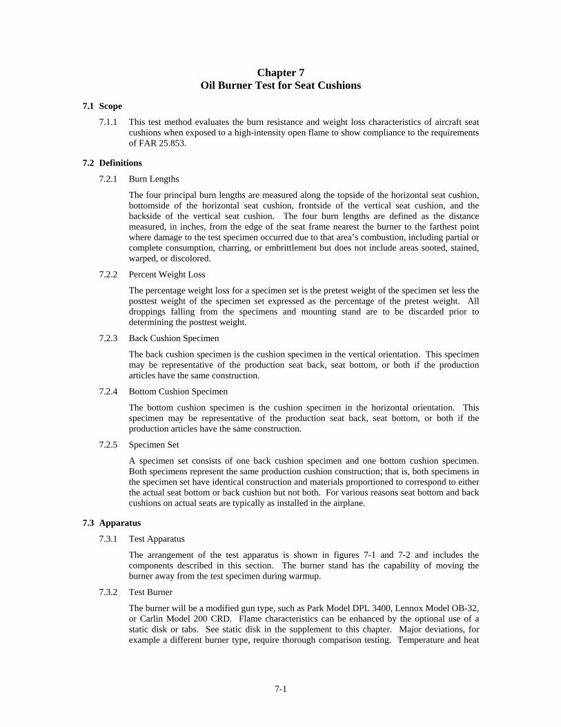
The arrangement of the test apparatus is shown in figures 7-1 and 7-2 and includes the components described in this section. The burner stand has the capability of moving the burner away from the test specimen during warmup.
7.3.2 Test Burner
The burner will be a modified gun type, such as Park Model DPL 3400, Lennox Model OB-32, or Carlin Model 200 CRD. Flame characteristics can be enhanced by the optional use of a static disk or tabs. See static disk in the supplement to this chapter. Major deviations, for example a different burner type, require thorough comparison testing. Temperature and heat
7-1
flux measurements, as well as test results, must correspond to those produced by an FAA approved burner.
Figure 7-1. Front, Side, and Top Views of Seat Oil Burner Specimen Frame
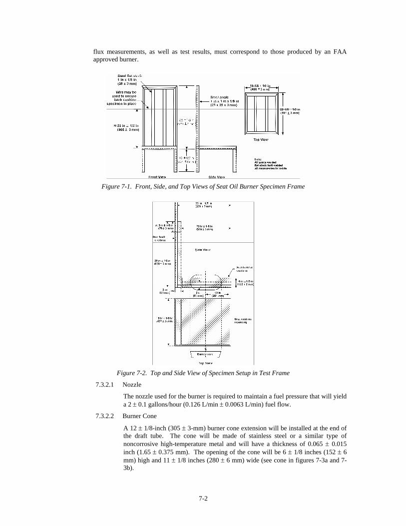
Figure 7-2. Top and Side View of Specimen Setup in Test Frame
7.3.2.1 Nozzle
The nozzle used for the burner is required to maintain a fuel pressure that will yield a 2 ± 0.1 gallons/hour (0.126 L/min ± 0.0063 L/min) fuel flow.
7.3.2.2 Burner Cone
A 12 ± 1/8-inch (305 ± 3-mm) burner cone extension will be installed at the end of the draft tube. The cone will be made of stainless steel or a similar type of noncorrosive high-temperature metal and will have a thickness of 0.065 ± 0.015 inch (1.65 ± 0.375 mm). The opening of the cone will be 6 ± 1/8 inches (152 ± 6 mm) high and 11 ± 1/8 inches (280 ± 6 mm) wide (see cone in figures 7-3a and 7-3b).
7-2
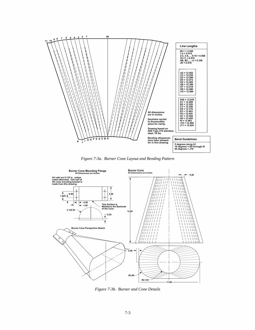
Figure 7-3a. Burner Cone Layout and Bending Pattern
Figure 7-3b. Burner and Cone Details
7-3
7.3.2.3 Fuel
ASTM K2 fuel (number 2 grade kerosene) or ASTM D2 fuel (number 2 grade fuel oil) will be used.
7.3.2.4 Fuel Pressure Regulator
A fuel pressure regulator adjusted to deliver 2 gallons/hour ± 0.1 gallon/hour (7.57 liters/hour ± 0.38 liter/hour) will be provided.
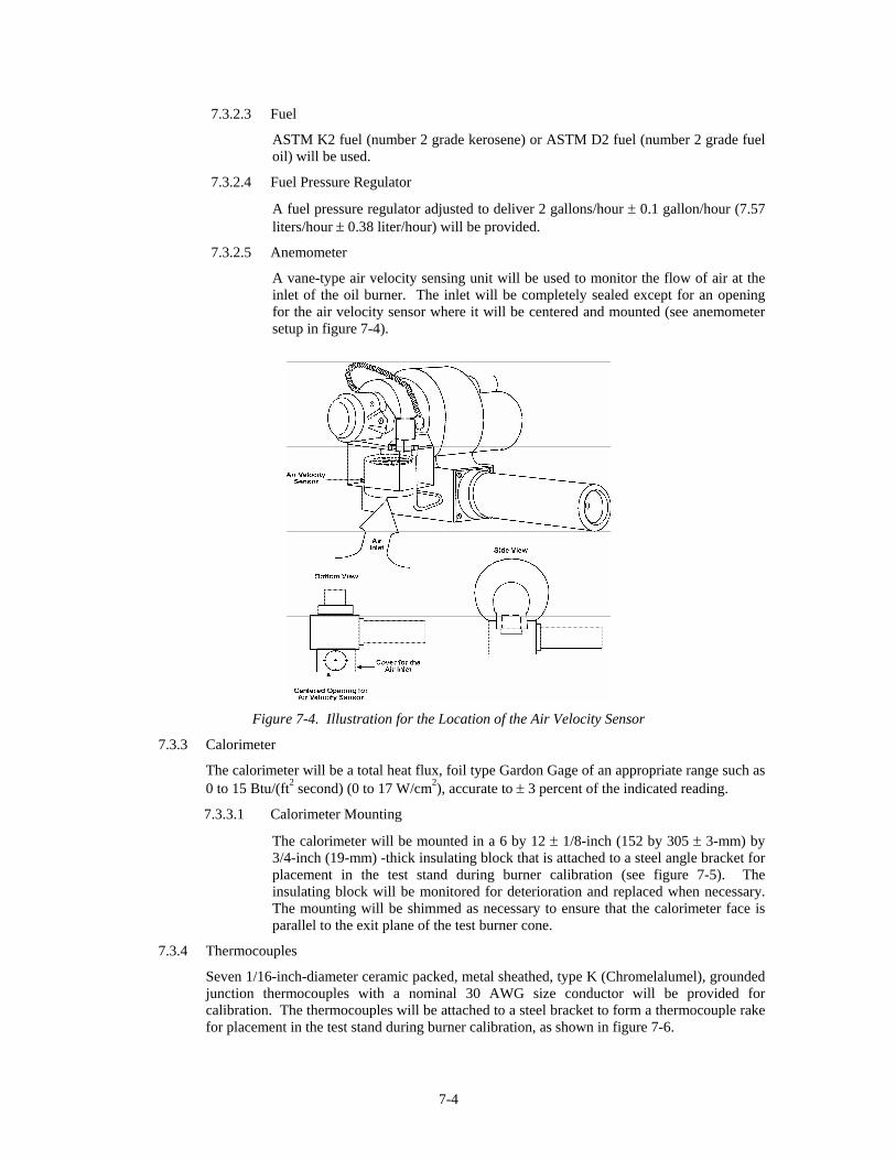
7.3.2.5 Anemometer
A vane-type air velocity sensing unit will be used to monitor the flow of air at the inlet of the oil burner. The inlet will be completely sealed except for an opening for the air velocity sensor where it will be centered and mounted (see anemometer setup in figure 7-4).
Figure 7-4. Illustration for the Location of the Air Velocity Sensor
7.3.3 Calorimeter
The calorimeter will be a total heat flux, foil type Gardon Gage of an appropriate range such as 0 to 15 Btu/(ft2 second) (0 to 17 W/cm2), accurate to ± 3 percent of the indicated reading.
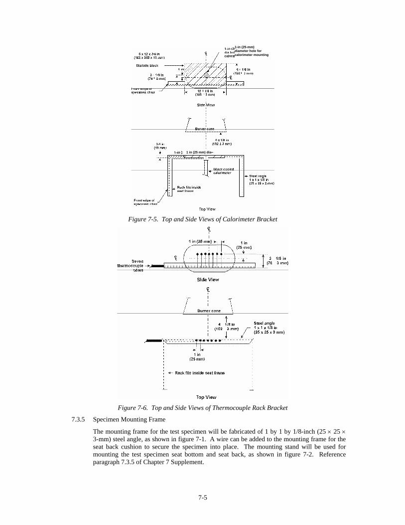
7.3.3.1 Calorimeter Mounting
The calorimeter will be mounted in a 6 by 12 ± 1/8-inch (152 by 305 ± 3-mm) by 3/4-inch (19-mm) -thick insulating block that is attached to a steel angle bracket for placement in the test stand during burner calibration (see figure 7-5). The insulating block will be monitored for deterioration and replaced when necessary. The mounting will be shimmed as necessary to ensure that the calorimeter face is parallel to the exit plane of the test burner cone.
7.3.4 Thermocouples
Seven 1/16-inch-diameter ceramic packed, metal sheathed, type K (Chromelalumel), grounded junction thermocouples with a nominal 30 AWG size conductor will be provided for calibration. The thermocouples will be attached to a steel bracket to form a thermocouple rake for placement in the test stand during burner calibration, as shown in figure 7-6.
7-4
1-in (25-mm) diameter hole for calorimeter mounting
1 in (25 mm) dia
Figure 7-5. Top and Side Views of Calorimeter Bracket
Figure 7-6. Top and Side Views of Thermocouple Rack Bracket
7.3.5 Specimen Mounting Frame
The mounting frame for the test specimen will be fabricated of 1 by 1 by 1/8-inch (25 × 25 × 3-mm) steel angle, as shown in figure 7-1. A wire can be added to the mounting frame for the seat back cushion to secure the specimen into place. The mounting stand will be used for mounting the test specimen seat bottom and seat back, as shown in figure 7-2. Reference paragraph 7.3.5 of Chapter 7 Supplement.
7-5
7.3.5.1 Drip Pan
The mounting stand will include a suitable drip pan lined with aluminum foil, dull side up. The drip pan will be located at the bottom of the mounting stand legs, 12 ± 1/8 inches (305 ± 3 mm) below the horizontal specimen holder.
7.3.6 Instrumentation
A calibrated recording device or a computerized data acquisition system with an appropriate range will be provided to measure and record the outputs of the calorimeter and the thermocouples.
7.3.7 Weight Scale
A weighing device will be provided to determine the pretest and posttest weights of each set of seat cushion specimens within 0.02 pound (9 g).
7.3.8 Timing Device
A stopwatch or other device, accurate to ± 1 second/hour, will be provided to measure the time of application of the burner flame and self-extinguishing time (or test duration).
7.4 Test Specimens
7.4.1 Specimen Preparation
A minimum of three specimen sets of the same construction and configuration will be prepared for testing.
7.4.2 Seat Bottom (Horizontal) Cushion Specimen
The constructed, finished specimen assembly will be 18 + 0, -1/8 inches (457 + 0, -3 mm) by 20 + 0,-1/8 inches (508 + 0, -3 mm) by 4 + 0, -1/8 inches (102 + 0, -3 mm), exclusive of fabric closures and seam overlap.
7.4.3 Seat Back (Vertical) Cushion Specimen
The constructed, finished specimen assembly will be 18 + 0, -1/8 inches (457 + 0, -3 mm) by 25 + 0, -1/8 inches (635 + 0, -3 mm), by 2 + 0, -1/8 inches (51 + 0, -3 mm), exclusive of fabric closures and seam overlap.
7.4.4 Construction
Each specimen tested will be fabricated using the principal components (i.e., foam core, flotation material, fire-blocking material, if used, and dress covering) and assembly processes (representative seams and closures) intended for use in the production articles. If a different material combination is used for the production back cushion than for the production bottom cushion, both material combinations will be tested as complete specimen sets. Each set will consist of a back cushion specimen and a bottom cushion specimen (see figure 7-7).
7.4.4.1 Fire-Blocking Material
If the cushion is constructed with a fire-blocking material, the fire-blocking material will completely enclose the cushion foam core material.
7.4.4.1.1 Specimen Fire-Blocking Fabrication
The method of fabricating blocking layer seams and closures will be the same as the production method. In fabricating the test specimen, the fire blocker will be configured so that any possible weak point is exposed to the burner flame. This may require configuring a test specimen so that the seam is exposed to the test burner, even though a seam may not be located there on a production cushion.
7-6
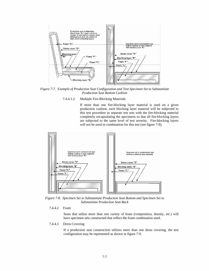
Figure 7-7. Example of Production Seat Configuration and Test Specimen Set to Substantiate
Production Seat Bottom Cushion
7.4.4.1.2 Multiple Fire-Blocking Materials
If more than one fire-blocking layer material is used on a given production cushion, each blocking layer material will be subjected to this test procedure as separate test sets with the fire-blocking material completely encapsulating the specimens so that all fire-blocking layers are subjected to the same level of test severity. Fire-blocking layers will not be used in combination for this test (see figure 7-8).
Figure 7-8. Specimen Set to Substantiate Production Seat Bottom and Specimen Set to
Substantiate Production Seat Back
7.4.4.2 Foam
Seats that utilize more than one variety of foam (composition, density, etc.) will have specimen sets constructed that reflect the foam combination used.
7.4.4.3 Dress Covering
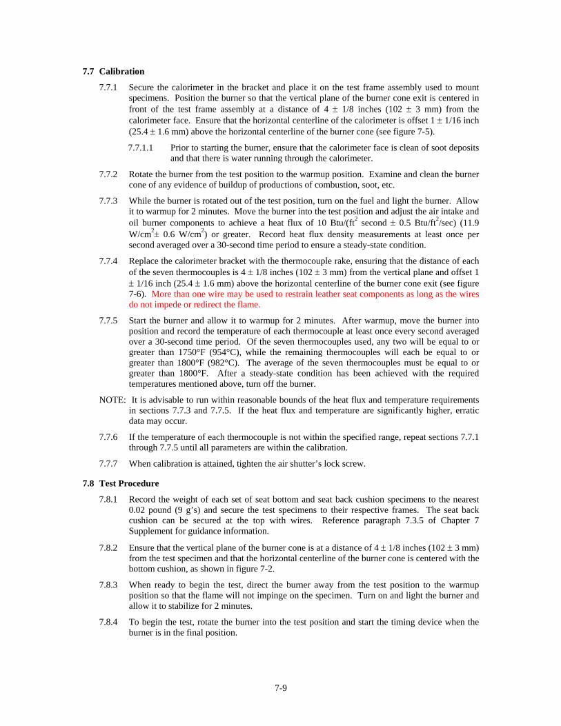
If a production seat construction utilizes more than one dress covering, the test configuration may be represented as shown in figure 7-9.
7-7
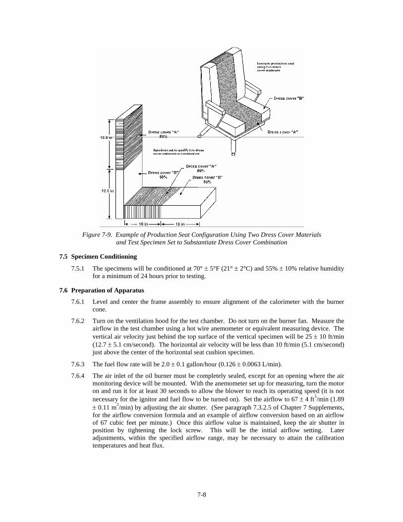
Figure 7-9. Example of Production Seat Configuration Using Two Dress Cover Materials
and Test Specimen Set to Substantiate Dress Cover Combination
7.5 Specimen Conditioning
7.5.1 The specimens will be conditioned at 70° ± 5°F (21° ± 2°C) and 55% ± 10% relative humidity for a minimum of 24 hours prior to testing.
7.6 Preparation of Apparatus
7.6.1 Level and center the frame assembly to ensure alignment of the calorimeter with the burner cone.
7.6.2 Turn on the ventilation hood for the test chamber. Do not turn on the burner fan. Measure the airflow in the test chamber using a hot wire anemometer or equivalent measuring device. The vertical air velocity just behind the top surface of the vertical specimen will be 25 ± 10 ft/min (12.7 ± 5.1 cm/second). The horizontal air velocity will be less than 10 ft/min (5.1 cm/second) just above the center of the horizontal seat cushion specimen.
7.6.3 The fuel flow rate will be 2.0 ± 0.1 gallon/hour (0.126 ± 0.0063 L/min).
7.6.4 The air inlet of the oil burner must be completely sealed, except for an opening where the air monitoring device will be mounted. With the anemometer set up for measuring, turn the motor on and run it for at least 30 seconds to allow the blower to reach its operating speed (it is not necessary for the ignitor and fuel flow to be turned on). Set the airflow to 67 ± 4 ft3/min (1.89 ± 0.11 m3/min) by adjusting the air shutter. (See paragraph 7.3.2.5 of Chapter 7 Supplements, for the airflow conversion formula and an example of airflow conversion based on an airflow of 67 cubic feet per minute.) Once this airflow value is maintained, keep the air shutter in position by tightening the lock screw. This will be the initial airflow setting. Later adjustments, within the specified airflow range, may be necessary to attain the calibration temperatures and heat flux.
7-8
7.7 Calibration
7.7.1 Secure the calorimeter in the bracket and place it on the test frame assembly used to mount specimens. Position the burner so that the vertical plane of the burner cone exit is centered in front of the test frame assembly at a distance of 4 ± 1/8 inches (102 ± 3 mm) from the calorimeter face. Ensure that the horizontal centerline of the calorimeter is offset 1 ± 1/16 inch (25.4 ± 1.6 mm) above the horizontal centerline of the burner cone (see figure 7-5).
7.7.1.1 Prior to starting the burner, ensure that the calorimeter face is clean of soot deposits and that there is water running through the calorimeter.
7.7.2 Rotate the burner from the test position to the warmup position. Examine and clean the burner cone of any evidence of buildup of productions of combustion, soot, etc.
7.7.3 While the burner is rotated out of the test position, turn on the fuel and light the burner. Allow it to warmup for 2 minutes. Move the burner into the test position and adjust the air intake and oil burner components to achieve a heat flux of 10 Btu/(ft2 second ± 0.5 Btu/ft2/sec) (11.9 W/cm2± 0.6 W/cm2) or greater. Record heat flux density measurements at least once per second averaged over a 30-second time period to ensure a steady-state condition.
7.7.4 Replace the calorimeter bracket with the thermocouple rake, ensuring that the distance of each of the seven thermocouples is 4 ± 1/8 inches (102 ± 3 mm) from the vertical plane and offset 1 ± 1/16 inch (25.4 ± 1.6 mm) above the horizontal centerline of the burner cone exit (see figure 7-6). More than one wire may be used to restrain leather seat components as long as the wires do not impede or redirect the flame.
7.7.5 Start the burner and allow it to warmup for 2 minutes. After warmup, move the burner into position and record the temperature of each thermocouple at least once every second averaged over a 30-second time period. Of the seven thermocouples used, any two will be equal to or greater than 1750°F (954°C), while the remaining thermocouples will each be equal to or greater than 1800°F (982°C). The average of the seven thermocouples must be equal to or greater than 1800°F. After a steady-state condition has been achieved with the required temperatures mentioned above, turn off the burner.
NOTE: It is advisable to run within reasonable bounds of the heat flux and temperature requirements in sections 7.7.3 and 7.7.5. If the heat flux and temperature are significantly higher, erratic data may occur.
7.7.6 If the temperature of each thermocouple is not within the specified range, repeat sections 7.7.1 through 7.7.5 until all parameters are within the calibration.
7.7.7 When calibration is attained, tighten the air shutter’s lock screw.
7.8 Test Procedure
7.8.1 Record the weight of each set of seat bottom and seat back cushion specimens to the nearest 0.02 pound (9 g’s) and secure the test specimens to their respective frames. The seat back cushion can be secured at the top with wires. Reference paragraph 7.3.5 of Chapter 7 Supplement for guidance information.
7.8.2 Ensure that the vertical plane of the burner cone is at a distance of 4 ± 1/8 inches (102 ± 3 mm) from the test specimen and that the horizontal centerline of the burner cone is centered with the bottom cushion, as shown in figure 7-2.
7.8.3 When ready to begin the test, direct the burner away from the test position to the warmup position so that the flame will not impinge on the specimen. Turn on and light the burner and allow it to stabilize for 2 minutes.
7.8.4 To begin the test, rotate the burner into the test position and start the timing device when the burner is in the final position.
7-9
7.8.5 Expose the test specimen to the burner flame for 2 minutes and then turn off the burner. Immediately rotate the burner out of the test position.
7.8.6 Terminate the test when the specimens self-extinguish. If the specimens do not self-extinguish after 5 minutes from the time the burner had been turned off, terminate the test by extinguishing the test specimens.
7.8.7 Immediately after test termination, determine the posttest weight of the remains of the seat cushion specimen set to the nearest 0.02 pound (9 g’s), excluding droppings.
7.8.8 Measure the four burn lengths. Reference paragraph 7.8.8 of Chapter 7 Supplement for help in determining burn length.
7.9 Report
7.9.1 Identify and describe the specimen being tested. Report the type of foam (flame retardant [FR] molded or cut); foam density, if known; and manufacturer and type of FR treatment if known.
7.9.2 Report the number of specimen sets tested.
7.9.3 Report the pretest and posttest weight of each set, the calculated percentage weight loss of each set, and the calculated average percentage weight for the total number of sets tested.
7.9.4 Report each of the four burn lengths for each set tested.
7.10 Requirements
7.10.1 For each of the burn lengths measured, the burn length may not exceed 17 inches (43.2 cm) on at least two-thirds of the total number of specimen sets tested. Additionally, the average burn length for each of the measured lengths will not exceed 17 inches.
7.10.2 The average percentage weight loss will not exceed 10 percent.
7.10.3 The weight loss of at least two-thirds of the total number of specimen sets tested will not exceed 10 percent.
7-10
Chapter 7 Supplement 7-11
Chapter 7 Supplement
This supplement contains advisory material pertinent to referenced paragraphs.
7.3.2.1 A Monarch 80°AR or 80°R nozzle nominally rated at 2.25 gal/hr (0.142 L/min) at 100 lb/in2
(0.71 MPa) and operated at 85 lb/in2 (0.6 MPa) gauge, has been found to deliver 2 gal/hr (0.126 L/min) and produce
a proper spray pattern. A Monarch 80° Constant Capacity (CC) nozzle, nominally rated at 2 gal/hr at 100 lb/in2 and
operated between 95 and 105 lb/in2 gauge is also acceptable. Minor deviations to the fuel nozzle spray angle, fuel
pressure, or other similar parameters are acceptable if the fuel flow rate, temperatures, and heat flux measurementsconform to the requirements of sections 7.6 and 7.7.
7.3.2.3 Number 2 diesel fuel, Jet A, or the international equivalent, is the recommended fuel because it has beenfound to produce satisfactory results if the fuel flow rate and inlet airflow conform to the requirements of sections7.6 and 7.7.
7.3.2.4 A fuel pressure regulator that is adjusted to deliver 2 ± 0.1 gal/hr (0.126 ± 0.0063 L/min) flow throughthe nozzle should be provided. An operating fuel pressure of 85 ± 4 psig (0.57 ± 0.03 MPa) for a 2.25 gallons/hour(0.142 L/min) 80° spray angle nozzle has been found satisfactory.
7.3.2.5 The Omega microprocessor-based portable air velocity kit, model HH-30, is a suitable unit. The unitmonitors air velocity in feet per minute (FPM) or meters per second (MPS) ± 1 percent reading accuracy, therefore,necessary conversions must be made to attain airflow values. To do this, the area of the opening of the air sensormust be measured. Once the area is found, install the air velocity sensor at the oil burner inlet. Following theprocedures prescribed in section 7.6.4, this value should be multiplied by the air velocity reading. The Omega modelHH-30 air velocity sensor’s area is 0.037 ft
2. (For example, to achieve an airflow of 67 ft
3/min, an air velocity
reading of 1811 ft/min must be maintained.)
Airflow = Air Velocity × Area of Opening (Air Velocity Sensor)
7.3.4 The thermocouples are periodically subjected to high temperatures during calibration. Because of this typeof cycling, the thermocouples may degrade with time. Small but continuing decreases or extreme variations intemperature or “no” temperature reading at all are signs that the thermocouple or thermocouples are degrading oropen circuits have occurred. In this case, the thermocouple or thermocouples should be replaced in order to maintainaccuracy in calibrating the burner. It is recommended that a record for the amount of time the thermocouples areexposed to the oil burner’s flame be kept.
7.3.5 A length of wire can be used to aid in securing the vertical seat cushion to the specimen frame(see figure 7-2). The wire should be uninsulated, solid, 0.032 inch (0.8 mm) or less in diameter and be located nomore than 1/2 inch (13 mm) from the top surface of the vertical specimen as it sits in the frame. The wire should notdisturb the flame spread behavior of the material(s) being tested. If the flame spread is affected, another wireconfiguration should be used.
7.3.7 A continuous weighing system is recommended as it allows the operator the ability to monitor weight lossduring the test.
7.4.4.2 If, however, several seat models use similar foam combinations, it is not necessary to test each combinationif it is possible to bracket the various combinations. For example, if foam “A” makes up 80 percent and foam “B”makes up 20 percent of the foam volume in one seat model and in another similar seat model, foam “A” makes up 20percent and foam “B” makes up 80 percent of the foam volume, it is generally acceptable to approve allcombinations of “A” and “B” foams between these limits if the 20/80 and 80/20 extremes are tested and pass. Inaddition, for foams of a given chemical composition, low-density foam can be used in lieu of foams of higherdensity. In this case, as in the case of foam combinations, all other elements that make up the cushion must be thesame (see figure 7-7).
Chapter 7 Supplement 7-12
7.4.4.3 When any seat construction tested has passed, a separate test is not required for another seat construction ifthe only difference from the first test is the dress covering, provided the replacement dress covering is comprised of asimilar weave design and fiber type, as described in section 7.4.4.3.2 and the burn length of the replacement dresscovering, as determined by the Bunsen burner test specified in FAR 25.853(b), does not exceed the burn length ofthe dress covering used for the test.
Test specimens are intended to represent the principal material elements and construction methods of the productionseats. Items decorative in nature, such as buttons, detail stitching, hand-hold straps, velcro attached strips, or thinouter cover paddings, such as armrest covers and filler around food trays, that do not penetrate the fire-blockinglayer when fastened are not required to be represented on the test specimen. Dress cover details and items notassociated with the cushion construction, such as metal seat pans or other metal structures, should not be included inthe specimen weight since they are not part of the principal seat construction. Layers of padding or fillerimmediately under the dress cover material are considered to be part of the dress cover material and should beincluded in the test specimens.
Similar dress covering (from Advisory Circular 25.853-1, “Flammability of Aircraft Seat Cushions,” Sections 5d[1]and [2]) refers to dress covering materials having the same material composition, weave style, and weight. Materialblends can be considered similar when the constituent materials fractions are the same, ± 6 percent, as the testedmaterial. Examples of different weave styles include plain, jacquard, or velvet. With regard to weight, lighterfabrics are generally more critical than heavier fabrics. Due to the severe shrinking and unpredictable distortionexperienced by leather dress cover materials, similarity approvals for leather are not recommended.
Certification by similarity to previously tested dress covers should be limited to instances where the material com-position is the same and the weight and weave type are essentially the same. In all cases, results of the Bunsenburner test per FAR 25.853(b) for the new material should be equal to or better with respect to burn length than thetested material. In addition, it may be useful to evaluate the weight loss and burn length results of the oil burner testto determine if the tested material is a good basis for similarity; that is, the closer weight loss and burn length withthe oil burner are to the maximum allowed, the more alike the dress covering materials should be for similarity. Ingeneral, test data and resultant experience gained from conducting tests should also be a major source of informationto determine if approval by similarity is acceptable.
7.6.2 The language of paragraph 7.6.2 in the handbook can be met by measuring the vertical air flow at fourpoints. These points are located behind the vertical specimen, 1/2 inch (113 mm) from the rear-facing verticalsurface, 2 inches (305 mm) below the vertical specimen top surface, 2 inches (305 mm) above the vertical specimenbottom surface, and horizontally positioned 6 inches (152 mm) from each side. The measurements do not need to bemade simultaneously, precluding the need for multiple anemometers. However, these measurements should be madein the same calibration cycle. The horizontal air velocity can be measured 1/2 inch (13 mm) above the geometriccenter of the upper horizontal surface.
7.6.3 If this measurement method is used to determine the fuel flow rate, the person(s) performing the measure-ment should realize that flammable vapors should be present in the test chamber. Caution must be exercised duringthe measurement period to avoid all possible ignition dangers.
If a calibrated flow meter is not available, measure the fuel flow rate using a 300 to 500 millimeter graduatedcylinder or beaker, a 1/2 inch (13 mm) or large diameter rubber or plastic drain tube, and a timer.
There are two items that need consideration because they can affect the measurement accuracy. First, if a tube ofinsufficient diameter is used, conduit flow in the tube should add an additional back pressure to the nozzle flow.Second, when reading the collection vessel to determine the fuel volume delivered by the nozzle, ensure that thevessel is level and the fluid level is measured by reading the height of the meniscus. If either of these items is notconsidered, grave errors in fuel flow measurement can result.
The directions for finding the fuel flow rate follow. Remove the oil burner draft tube. Place the drain tube over thenozzle orifice. Drape the tube into the collection vessel, which is at a level lower than the nozzle. Ensure that the
Chapter 7 Supplement 7-13
ignitor system is turned off, then turn on the fuel pump and burner motor. Collect the fuel in the graduated cylinderor beaker for a 2-minute period. Measure the fuel volume delivered and calculate the fuel flow rate.
2 gallons/hour = 126 millimeters/minute
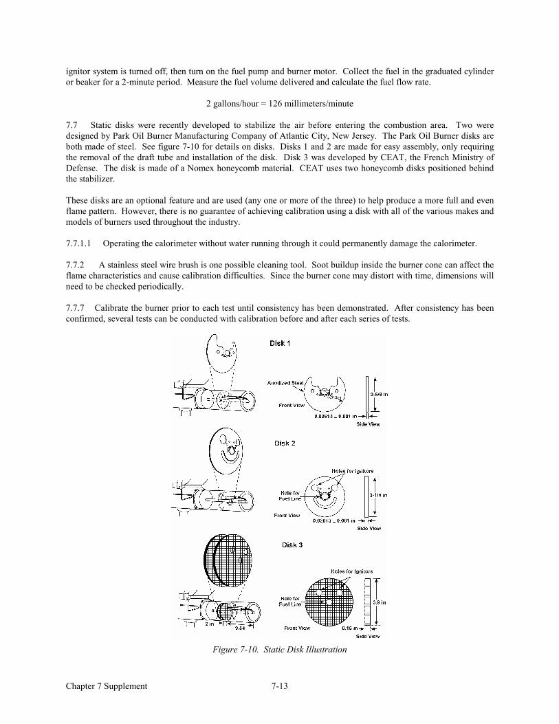
7.7 Static disks were recently developed to stabilize the air before entering the combustion area. Two weredesigned by Park Oil Burner Manufacturing Company of Atlantic City, New Jersey. The Park Oil Burner disks areboth made of steel. See figure 7-10 for details on disks. Disks 1 and 2 are made for easy assembly, only requiringthe removal of the draft tube and installation of the disk. Disk 3 was developed by CEAT, the French Ministry ofDefense. The disk is made of a Nomex honeycomb material. CEAT uses two honeycomb disks positioned behindthe stabilizer.
These disks are an optional feature and are used (any one or more of the three) to help produce a more full and evenflame pattern. However, there is no guarantee of achieving calibration using a disk with all of the various makes andmodels of burners used throughout the industry.
7.7.1.1 Operating the calorimeter without water running through it could permanently damage the calorimeter.
7.7.2 A stainless steel wire brush is one possible cleaning tool. Soot buildup inside the burner cone can affect theflame characteristics and cause calibration difficulties. Since the burner cone may distort with time, dimensions willneed to be checked periodically.
7.7.7 Calibrate the burner prior to each test until consistency has been demonstrated. After consistency has beenconfirmed, several tests can be conducted with calibration before and after each series of tests.
Figure 7-10. Static Disk Illustration
Chapter 7 Supplement 7-14
Recommendations for achieving calibration temperatures:
1. Set the stabilizer 3.25 ± 0.25 inches from the end of the draft tube.
2. Rotate the ignitor to the 6 o’clock and 9 o’clock position (viewpoint: looking toward the stabilizer fromthe end of the draft tube).
3. Seal all possible air leaks around the burner cone and draft tube area.
4. Use static disk to improve flame characteristics. See figure 7.9 for information on disks.
7.8.8 An industry practice acceptable to the FAA for determining specimen damage length, in order to measureburn length, has been to use an object with a dull point, such as a pencil, and scrape the dress covering. If the objectused penetrates the dress covering, damage has occurred due to that area’s combustion. If the dress covering is notpenetrated, damage has occurred due to pyrolysis and is not considered damaged by combustion.


![Nozzle-mix line burner - Maxon Corporation · [5] Pressure differential between burner test connection and combus tion chamber for natural gas to be used for burner commissioning](https://img.pdfslide.us/doc/110x75/5cc4d1e588c993ab2a8c9219/nozzle-mix-line-burner-maxon-corporation-5-pressure-differential-between.jpg)