Embed Size (px)
Citation preview
Chapter 7 7-1
(October 2017)
Chapter 7
Oil Burner Test for Seat Cushions
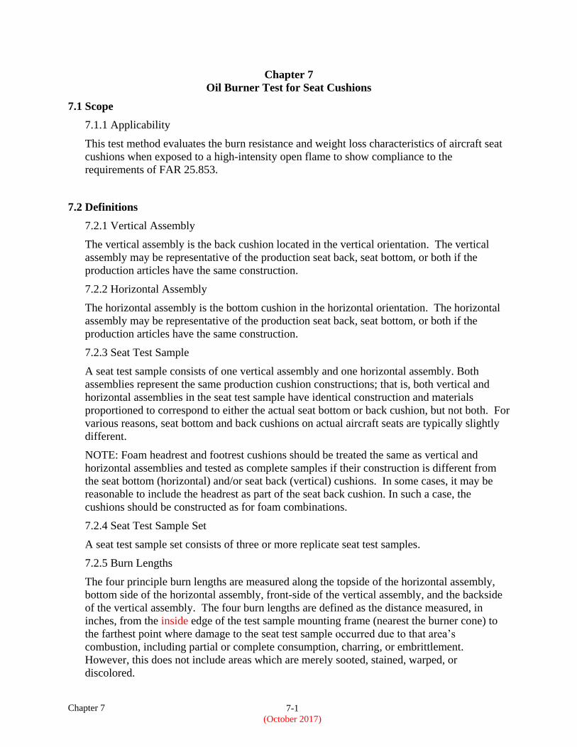
7.1 Scope
7.1.1 Applicability
This test method evaluates the burn resistance and weight loss characteristics of aircraft seat
cushions when exposed to a high-intensity open flame to show compliance to the
requirements of FAR 25.853.
7.2 Definitions
7.2.1 Vertical Assembly
The vertical assembly is the back cushion located in the vertical orientation. The vertical
assembly may be representative of the production seat back, seat bottom, or both if the
production articles have the same construction.
7.2.2 Horizontal Assembly
The horizontal assembly is the bottom cushion in the horizontal orientation. The horizontal
assembly may be representative of the production seat back, seat bottom, or both if the
production articles have the same construction.
7.2.3 Seat Test Sample
A seat test sample consists of one vertical assembly and one horizontal assembly. Both
assemblies represent the same production cushion constructions; that is, both vertical and
horizontal assemblies in the seat test sample have identical construction and materials
proportioned to correspond to either the actual seat bottom or back cushion, but not both. For
various reasons, seat bottom and back cushions on actual aircraft seats are typically slightly
different.
NOTE: Foam headrest and footrest cushions should be treated the same as vertical and
horizontal assemblies and tested as complete samples if their construction is different from
the seat bottom (horizontal) and/or seat back (vertical) cushions. In some cases, it may be
reasonable to include the headrest as part of the seat back cushion. In such a case, the
cushions should be constructed as for foam combinations.
7.2.4 Seat Test Sample Set
A seat test sample set consists of three or more replicate seat test samples.
7.2.5 Burn Lengths
The four principle burn lengths are measured along the topside of the horizontal assembly,
bottom side of the horizontal assembly, front-side of the vertical assembly, and the backside
of the vertical assembly. The four burn lengths are defined as the distance measured, in
inches, from the inside edge of the test sample mounting frame (nearest the burner cone) to
the farthest point where damage to the seat test sample occurred due to that area’s
combustion, including partial or complete consumption, charring, or embrittlement.
However, this does not include areas which are merely sooted, stained, warped, or
discolored.
Chapter 7 7-2
(October 2017)
7.2.6 Percent Weight Loss
The percentage weight loss for a seat test sample is the pretest weight of the seat test sample
less the posttest weight of the seat test sample expressed as the percentage of the pretest
weight. All droppings falling from the seat test sample and test sample mounting frame are
to be discarded prior to determining the posttest weight.
7.3 Apparatus
7.3.1 Test Sample Apparatus
The test sample apparatus includes the seat test sample mounting frame and drip pan. The
arrangement of the test sample apparatus is shown in figures 7-1 and 7-2.
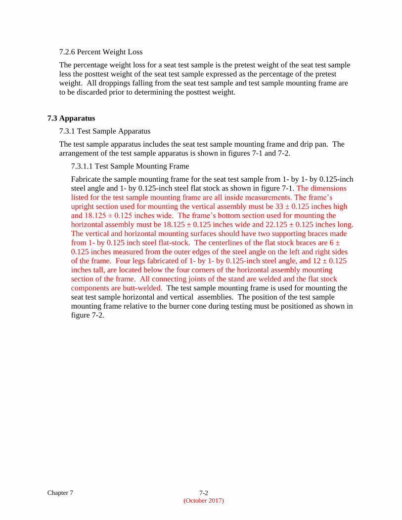
7.3.1.1 Test Sample Mounting Frame
Fabricate the sample mounting frame for the seat test sample from 1- by 1- by 0.125-inch
steel angle and 1- by 0.125-inch steel flat stock as shown in figure 7-1. The dimensions
listed for the test sample mounting frame are all inside measurements. The frame’s
upright section used for mounting the vertical assembly must be 33 ± 0.125 inches high
and 18.125 ± 0.125 inches wide. The frame’s bottom section used for mounting the
horizontal assembly must be 18.125 ± 0.125 inches wide and 22.125 ± 0.125 inches long.
The vertical and horizontal mounting surfaces should have two supporting braces made
from 1- by 0.125 inch steel flat-stock. The centerlines of the flat stock braces are 6 ±
0.125 inches measured from the outer edges of the steel angle on the left and right sides
of the frame. Four legs fabricated of 1- by 1- by 0.125-inch steel angle, and 12 ± 0.125
inches tall, are located below the four corners of the horizontal assembly mounting
section of the frame. All connecting joints of the stand are welded and the flat stock
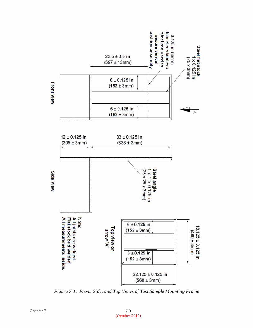
components are butt-welded. The test sample mounting frame is used for mounting the
seat test sample horizontal and vertical assemblies. The position of the test sample
mounting frame relative to the burner cone during testing must be positioned as shown in
figure 7-2.
Chapter 7 7-3
(October 2017)
Figure 7-1. Front, Side, and Top Views of Test Sample Mounting Frame
Chapter 7 7-4
(October 2017)
Figure 7-2. Top and Side View of Seat Test Sample in Test Sample Mounting Frame
Chapter 7 7-5
(October 2017)
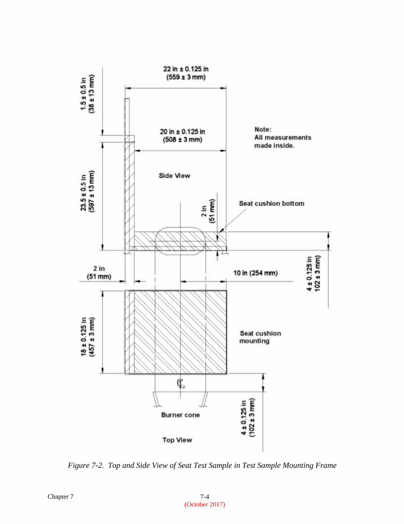
7.3.1.1.1 Restraint Method for Fabric Dress Covered Samples
A stainless steel rod will be used to aid in securing the vertical seat cushion to the
sample frame (figure 7-2). The rod will be uninsulated, solid, 0.125-inch (3-mm) in
diameter and be located 1.5 ± 0.5 inches (38 ± 13 mm) from the top surface of the
vertical cushion assembly as it sits in the sample test frame (figure 7-3).
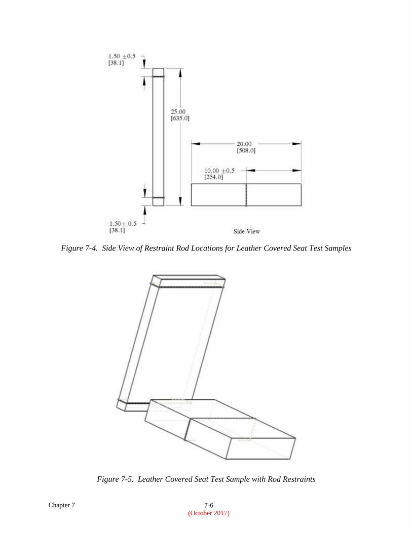
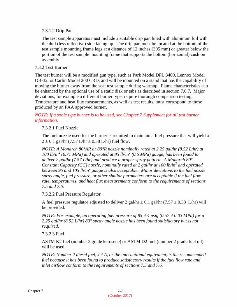
7.3.1.1.2 Restraint Method for Leather Dress Covered Samples
Due to leather’s tendency to shrink away from the flame during testing, both the
vertical and horizontal cushion assemblies will require rod restraints. The rods must
be uninsulated, solid stainless steel measuring 0.125-inch (3-mm) in diameter (figure
7-3). Two rods must be used to restrain the vertical assembly and one rod must be
used to restrain the horizontal assembly as shown in figures 7-4 and 7-5.
Figure 7-3. Vertical Assembly and Horizontal Assembly Restraint Rods
Chapter 7 7-6
(October 2017)
Figure 7-4. Side View of Restraint Rod Locations for Leather Covered Seat Test Samples
Figure 7-5. Leather Covered Seat Test Sample with Rod Restraints
Chapter 7 7-7
(October 2017)
7.3.1.2 Drip Pan
The test sample apparatus must include a suitable drip pan lined with aluminum foil with
the dull (less reflective) side facing up. The drip pan must be located at the bottom of the
test sample mounting frame legs at a distance of 12 inches (305 mm) or greater below the
portion of the test sample mounting frame that supports the bottom (horizontal) cushion
assembly.
7.3.2 Test Burner
The test burner will be a modified gun type, such as Park Model DPL 3400, Lennox Model
OB-32, or Carlin Model 200 CRD, and will be mounted on a stand that has the capability of
moving the burner away from the seat test sample during warmup. Flame characteristics can
be enhanced by the optional use of a static disk or tabs as described in section 7.6.7. Major
deviations, for example a different burner type, require thorough comparison testing.
Temperature and heat flux measurements, as well as test results, must correspond to those
produced by an FAA approved burner.
NOTE: If a sonic type burner is to be used, see Chapter 7 Supplement for all test burner
information.
7.3.2.1 Fuel Nozzle
The fuel nozzle used for the burner is required to maintain a fuel pressure that will yield a
2 0.1 gal/hr (7.57 L/hr 0.38 L/hr) fuel flow.
NOTE: A Monarch 80°AR or 80°R nozzle nominally rated at 2.25 gal/hr (8.52 L/hr) at
100 lb/in2 (0.71 MPa) and operated at 85 lb/in
2 (0.6 MPa) gauge, has been found to
deliver 2 gal/hr (7.57 L/hr) and produce a proper spray pattern. A Monarch 80°
Constant Capacity (CC) nozzle, nominally rated at 2 gal/hr at 100 lb/in2 and operated
between 95 and 105 lb/in2 gauge is also acceptable. Minor deviations to the fuel nozzle
spray angle, fuel pressure, or other similar parameters are acceptable if the fuel flow
rate, temperatures, and heat flux measurements conform to the requirements of sections
7.5 and 7.6.
7.3.2.2 Fuel Pressure Regulator
A fuel pressure regulator adjusted to deliver 2 gal/hr 0.1 gal/hr (7.57 ± 0.38 L/hr) will
be provided.
NOTE: For example, an operating fuel pressure of 85 4 psig (0.57 0.03 MPa) for a
2.25 gal/hr (8.52 L/hr) 80° spray angle nozzle has been found satisfactory but is not
required.
7.3.2.3 Fuel
ASTM K2 fuel (number 2 grade kerosene) or ASTM D2 fuel (number 2 grade fuel oil)
will be used.
NOTE: Number 2 diesel fuel, Jet A, or the international equivalent, is the recommended
fuel because it has been found to produce satisfactory results if the fuel flow rate and
inlet airflow conform to the requirements of sections 7.5 and 7.6.
Chapter 7 7-8
(October 2017)
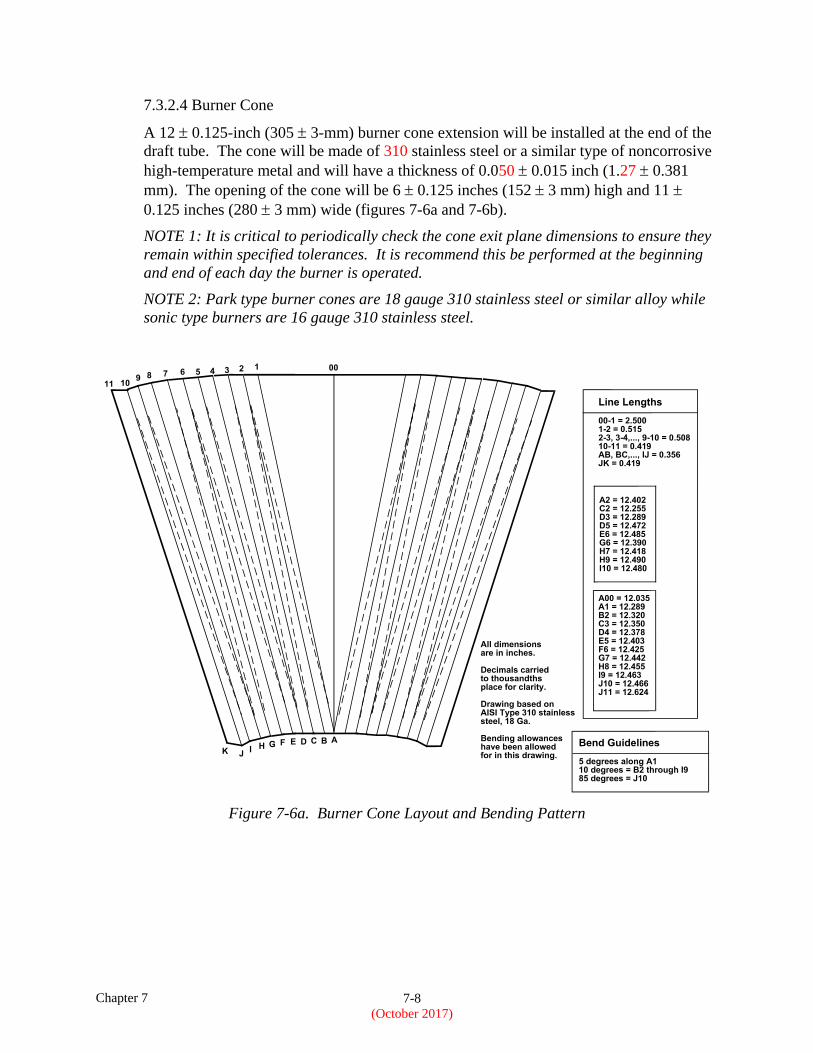
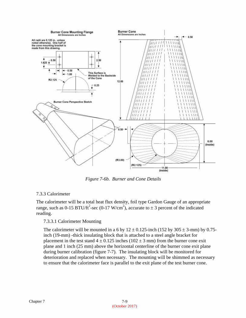
7.3.2.4 Burner Cone
A 12 0.125-inch (305 3-mm) burner cone extension will be installed at the end of the
draft tube. The cone will be made of 310 stainless steel or a similar type of noncorrosive
high-temperature metal and will have a thickness of 0.050 0.015 inch (1.27 0.381
mm). The opening of the cone will be 6 0.125 inches (152 3 mm) high and 11
0.125 inches (280 3 mm) wide (figures 7-6a and 7-6b).
NOTE 1: It is critical to periodically check the cone exit plane dimensions to ensure they
remain within specified tolerances. It is recommend this be performed at the beginning
and end of each day the burner is operated.
NOTE 2: Park type burner cones are 18 gauge 310 stainless steel or similar alloy while
sonic type burners are 16 gauge 310 stainless steel.
Figure 7-6a. Burner Cone Layout and Bending Pattern
Chapter 7 7-9
(October 2017)
Figure 7-6b. Burner and Cone Details
7.3.3 Calorimeter
The calorimeter will be a total heat flux density, foil type Gardon Gauge of an appropriate
range, such as 0-15 BTU/ft2-sec (0-17 W/cm
2), accurate to 3 percent of the indicated
reading.
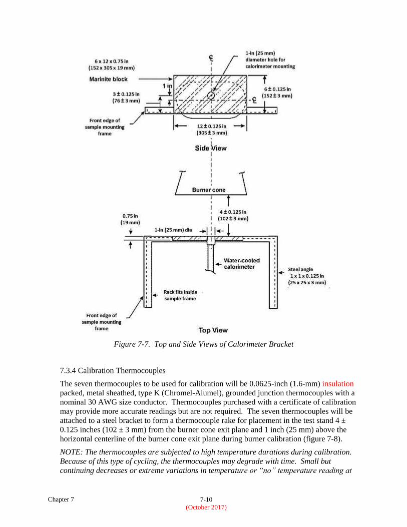
7.3.3.1 Calorimeter Mounting
The calorimeter will be mounted in a 6 by 12 0.125-inch (152 by 305 3-mm) by 0.75-
inch (19-mm) -thick insulating block that is attached to a steel angle bracket for
placement in the test stand 4 ± 0.125 inches (102 ± 3 mm) from the burner cone exit
plane and 1 inch (25 mm) above the horizontal centerline of the burner cone exit plane
during burner calibration (figure 7-7). The insulating block will be monitored for
deterioration and replaced when necessary. The mounting will be shimmed as necessary
to ensure that the calorimeter face is parallel to the exit plane of the test burner cone.
Chapter 7 7-10
(October 2017)
Figure 7-7. Top and Side Views of Calorimeter Bracket
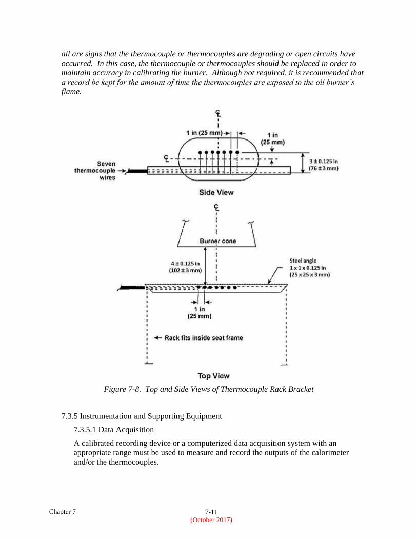
7.3.4 Calibration Thermocouples
The seven thermocouples to be used for calibration will be 0.0625-inch (1.6-mm) insulation
packed, metal sheathed, type K (Chromel-Alumel), grounded junction thermocouples with a
nominal 30 AWG size conductor. Thermocouples purchased with a certificate of calibration
may provide more accurate readings but are not required. The seven thermocouples will be
attached to a steel bracket to form a thermocouple rake for placement in the test stand 4 ±
0.125 inches (102 ± 3 mm) from the burner cone exit plane and 1 inch (25 mm) above the
horizontal centerline of the burner cone exit plane during burner calibration (figure 7-8).
NOTE: The thermocouples are subjected to high temperature durations during calibration.
Because of this type of cycling, the thermocouples may degrade with time. Small but
continuing decreases or extreme variations in temperature or “no” temperature reading at
Chapter 7 7-11
(October 2017)
all are signs that the thermocouple or thermocouples are degrading or open circuits have
occurred. In this case, the thermocouple or thermocouples should be replaced in order to
maintain accuracy in calibrating the burner. Although not required, it is recommended that
a record be kept for the amount of time the thermocouples are exposed to the oil burner’s
flame.
Figure 7-8. Top and Side Views of Thermocouple Rack Bracket
7.3.5 Instrumentation and Supporting Equipment
7.3.5.1 Data Acquisition
A calibrated recording device or a computerized data acquisition system with an
appropriate range must be used to measure and record the outputs of the calorimeter
and/or the thermocouples.
Chapter 7 7-12
(October 2017)
7.3.5.2 Timing Device
A stopwatch or other device, accurate to within ± 1 second per 8 hours (± 3 seconds/day),
must be used to measure the time of application of the burner flame, and the seat test
sample extinguishment times.
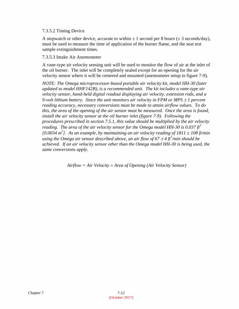
7.3.5.3 Intake Air Anemometer
A vane-type air velocity sensing unit will be used to monitor the flow of air at the inlet of
the oil burner. The inlet will be completely sealed except for an opening for the air
velocity sensor where it will be centered and mounted (anemometer setup in figure 7-9).
NOTE: The Omega microprocessor-based portable air velocity kit, model HH-30 (later
updated to model HHF142B), is a recommended unit. The kit includes a vane-type air
velocity sensor, hand-held digital readout displaying air velocity, extension rods, and a
9-volt lithium battery. Since the unit monitors air velocity in FPM or MPS 1 percent
reading accuracy, necessary conversions must be made to attain airflow values. To do
this, the area of the opening of the air sensor must be measured. Once the area is found,
install the air velocity sensor at the oil burner inlet (figure 7-9). Following the
procedures prescribed in section 7.5.1, this value should be multiplied by the air velocity
reading. The area of the air velocity sensor for the Omega model HH-30 is 0.037 ft2
[0.0034 m2]. As an example, by maintaining an air velocity reading of 1811 ± 108 ft/min
using the Omega air sensor described above, an air flow of 67 4 ft3/min should be
achieved. If an air velocity sensor other than the Omega model HH-30 is being used, the
same conversions apply.
Airflow = Air Velocity Area of Opening (Air Velocity Sensor)
Chapter 7 7-13
(October 2017)
Figure 7-9. Illustration for the Location of the Air Velocity Sensor
7.3.5.4 Digital Weight Scale
A suitable weight scale must be used to determine the initial and final weights of the seat
test sample. The scale must have a resolution of 0.02 lbs (0.01 kgs) and an accuracy of ±
0.02 lbs (± 0.01 kgs).
7.3.5.5 Test Chamber
A suitable test chamber must be used to reduce or eliminate the possibility of test
fluctuation due to air movement. Although not required, the recommended minimum of
the test chamber floor area is 15 feet by 15 feet (4.57 m by 4.57 m) or larger.
NOTE: Smaller test cells may experience significant increases in ambient air temperature
while testing. This may increase the severity of the test.
7.3.5.6 Ventilation Hood
The test chamber must have an exhaust system capable of removing the products of
combustion expelled during the tests.
7.3.5.7 Test Chamber Anemometer
A handheld vane-type or hot-wire type air velocity sensing unit capable of measuring
accurately in the 0-100 ft/min range must be used to monitor the flow of air inside the test
Chapter 7 7-14
(October 2017)
chamber when the ventilation hood is operating. Air flow measurements should be taken
at the beginning of the day prior to operating the test burner as described in section 7.5.4.
NOTE: A suitable hotwire anemometer, which may be mounted to the sample test frame,
is manufactured by Dwyer Instruments, model number 641-6-LED. A suitable handheld
hotwire anemometer is manufactured by TSI, model number 9515. Vane-type
anemometers typically do not function properly with airflow rates less than 50 ft/min.
7.4 Test Samples
7.4.1 Vertical Assembly (Back Cushion)
The constructed, finished vertical assembly must be 18 + 0, -0.125 inches (457 + 0, -3 mm)
by 25 + 0, -0.125 inches (635 + 0, -3 mm), by 2 + 0, -0.125 inches (51 + 0, -3 mm), not
including fabric closures (hook and loop, etc.) and seam overlap.
7.4.2 Horizontal Assembly (Bottom Cushion)
The constructed, finished horizontal assembly must be 18 + 0, -0.125 inches (457 + 0, -3
mm) by 20 + 0, -0.125 inches (508 + 0, -3 mm) by 4 + 0, -0.125 inches (102 + 0, -3 mm), not
including fabric closures (hook and loop, etc.) and seam overlap.
7.4.3 Seat Test Sample Number
A minimum of three seat test samples of the same construction and configuration must be
prepared for testing.
7.4.4 Test Sample Fabrication
Each seat test sample tested must be fabricated using the principal components (i.e., foam
core, floatation material, fire blocking material, if used, and dress covering) and assembly
processes (representative seams and closures) intended for use in the production articles. If a
different material combination is used for the production back cushion than for the
production bottom cushion, both material combinations must be tested as a complete seat test
sample. Each seat test sample will consist of a vertical assembly and a horizontal assembly
(figure 7-10).
NOTE: For lightweight seat test samples (test samples weighing less than 3 lbs.), refer to
policy memo 25.853-1:
http://rgl.faa.gov/Regulatory_and_Guidance_Library/rgPolicy.nsf/0/4fd585eef694ebc486257
5a700690bd4/$FILE/ANM-115-07-002.pdf
7.4.4.1 Fire-Blocking Material
If a cushion is constructed with a fire-blocking material, the fire-blocking material must
completely enclose the cushion foam core material.
7.4.4.1.1 Seat Test Sample Fire-Blocking Fabrication
The method of fabricating blocking layer seams and closures must be the same as the
production method. In fabricating a seat test sample, the fire blocker must be
configured so that any possible weak point is exposed to the burner flame. This may
Chapter 7 7-15
(October 2017)
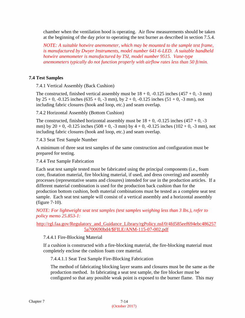
require configuring a seat test sample so that the seam is exposed to the test burner,
even though a seam may not be positioned as such on a production cushion.
Figure 7-10. Example of Production Seat Configuration and Seat Test Sample to Substantiate
Production Seat Bottom Cushion with Blocking Layer “B”
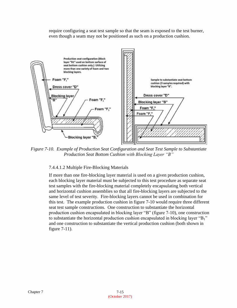
7.4.4.1.2 Multiple Fire-Blocking Materials
If more than one fire-blocking layer material is used on a given production cushion,
each blocking layer material must be subjected to this test procedure as separate seat
test samples with the fire-blocking material completely encapsulating both vertical
and horizontal cushion assemblies so that all fire-blocking layers are subjected to the
same level of test severity. Fire-blocking layers cannot be used in combination for
this test. The example production cushion in figure 7-10 would require three different
seat test sample constructions. One construction to substantiate the horizontal
production cushion encapsulated in blocking layer “B” (figure 7-10), one construction
to substantiate the horizontal production cushion encapsulated in blocking layer “B1”
and one construction to substantiate the vertical production cushion (both shown in
figure 7-11).
Chapter 7 7-16
(October 2017)
Figure 7-11. Seat Test Sample to Substantiate Production Seat Bottom with Blocking
Layer “B1” and Seat Test Sample to Substantiate Production Seat Back with Blocking
Layer “B”
7.4.4.2 Foam
Seats that utilize more than one variety of foam (composition, density, etc.) will have seat
test samples constructed that reflect the foam combination used.
NOTE: If several seat models use similar foam combinations, it is not necessary to test
each combination if it is possible to bracket the various combinations. For example, if
foam “A” makes up 80 percent and foam “B” makes up 20 percent of the foam volume in
one seat model and in another similar seat model, foam “A” makes up 20 percent and
foam “B” makes up 80 percent of the foam volume, it is generally acceptable to approve
all combinations of “A” and “B” foams between these limits if the 20/80 and 80/20
extremes are tested and pass. In addition, for foams of a given chemical composition,
low-density foam can be used in lieu of foams of higher density. In this case, as in the
case of foam combinations, all other elements that make up the cushion must be the same
(figure 7-10).
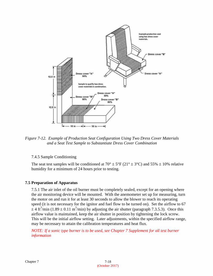
7.4.4.3 Dress Covering
If a production seat construction utilizes more than one dress covering, the seat test
sample configuration may be represented as shown in figure 7-12.
NOTE: When any seat construction tested has passed, a separate test is not required for
another seat construction if the only difference from the first test is the dress covering,
provided the replacement dress covering is comprised of a similar weave design and fiber
type, as described in section 7.4.4.3 and the burn length of the replacement dress
Chapter 7 7-17
(October 2017)
covering, as determined by the Bunsen burner test specified in FAR 25.853(a), does not
exceed the burn length of the dress covering used for the test.
Seat test samples are intended to represent the principal material elements and
construction methods of the production seats. Items decorative in nature, such as buttons,
detail stitching, hand-hold straps, Velcro® attached strips, or thin outer cover paddings,
such as armrest covers and filler around food trays, that do not penetrate the fire-blocking
layer when fastened are not required to be represented on the test sample. Dress cover
details and items not associated with the cushion construction, such as metal seat pans or
other metal structures, should not be included in the sample weight since they are not part
of the principal seat construction. Layers of padding or filler immediately under the dress
cover material are considered to be part of the dress cover material and should be
included in the seat test samples.
Similar dress covering (from Advisory Circular 25.853-1, “Flammability of Aircraft Seat
Cushions,” Sections 5d[1] and [2]) refers to dress covering materials having the same
material composition, weave style, and weight. Material blends can be considered
similar when the constituent materials fractions are the same, 6 percent, as the tested
material. Examples of different weave styles include plain, jacquard, or velvet. With
regard to weight, lighter fabrics are generally more critical than heavier fabrics. Due to
the severe shrinking and unpredictable distortion experienced by leather dress cover
materials, similarity approvals for leather are not recommended.
Certification by similarity to previously tested dress covers should be limited to instances
where the material composition is the same and the weight and weave type are essentially
the same. In all cases, results of the Bunsen burner test per FAR 25.853(a) for the new
material should be equal to or better with respect to burn length than the tested material.
In addition, it may be useful to evaluate the weight loss and burn length results of the oil
burner test to determine if the tested material is a good basis for similarity; that is, the
closer weight loss and burn length with the oil burner are to the maximum allowed, the
more alike the dress covering materials should be for similarity. In general, test data and
resultant experience gained from conducting tests should also be a major source of
information to determine if approval by similarity is acceptable.
Chapter 7 7-18
(October 2017)
Figure 7-12. Example of Production Seat Configuration Using Two Dress Cover Materials
and a Seat Test Sample to Substantiate Dress Cover Combination
7.4.5 Sample Conditioning
The seat test samples will be conditioned at 70° 5°F (21° 3°C) and 55% 10% relative
humidity for a minimum of 24 hours prior to testing.
7.5 Preparation of Apparatus
7.5.1 The air inlet of the oil burner must be completely sealed, except for an opening where
the air monitoring device will be mounted. With the anemometer set up for measuring, turn
the motor on and run it for at least 30 seconds to allow the blower to reach its operating
speed (it is not necessary for the ignitor and fuel flow to be turned on). Set the airflow to 67
4 ft3/min (1.89 0.11 m
3/min) by adjusting the air shutter (paragraph 7.3.5.3). Once this
airflow value is maintained, keep the air shutter in position by tightening the lock screw.
This will be the initial airflow setting. Later adjustments, within the specified airflow range,
may be necessary to attain the calibration temperatures and heat flux.
NOTE: If a sonic type burner is to be used, see Chapter 7 Supplement for all test burner
information
Chapter 7 7-19
(October 2017)
7.5.2 The fuel flow rate will be 2.0 0.1 gal/hr (7.57 0.38 L/hr).
NOTE 1: If a calibrated flow meter is not available, measure the fuel flow directly using a
length of Tygon® tubing and appropriately sized graduated cylinder. Slip the Tygon®
tubing over the end of the fuel nozzle, making certain to establish a good seal. Direct the exit
of the Tygon® tubing into a small bucket or other collection basin. Turn on the fuel
solenoid, making sure the ignition system is off. After establishing a steady stream of fuel
flow, simultaneously direct the tubing exit into the graduated cylinder while beginning the
stopwatch or timing device. Collect the fuel for a 2-minute period, making certain to
immediately direct the tubing exit away from the graduated cylinder at precisely 2 minutes.
Calculate the flow rate and ensure that it is 2 0.1 gal/hr (7.57 0.38 L/hr). If the flow rate
is not within the tolerance, adjust the fuel pressure accordingly.
NOTE 2: It is important to establish a steady stream of fuel before starting the fuel flow
measurement process. It is recommended the fuel flow steadily from the hose for a minimum
10-second period before collecting fuel in the graduated cylinder.
7.5.3 Mount a test sample on the test sample frame. Level and center the sample test frame
to ensure proper alignment with the burner cone. With the sample and test frame in the test
position in front of the burner cone, check for proper alignment (i.e., distance from exit of
burner cone to face of test sample, proper sample position with respect to cone centerline,
etc.). The movable burner or sample frame should incorporate mechanical stops or detents to
ensure correct positioning without measurement during testing.
7.5.4 Turn on the ventilation hood for the test chamber. Do not turn on the burner air, fuel,
or ignition. With the sample still in place, measure the airflow in the test chamber using a
hot wire anemometer or equivalent measuring device. The vertical air velocity just behind
the top surface of the vertical (cushion) assembly will be 25 10 ft/min (12.7 5.1
cm/second). The horizontal air velocity will be less than 10 ft/min (5.1 cm/second) just
above the center of the horizontal (cushion) assembly.
NOTE 1: SONIC BURNER ONLY: The vertical air velocity can be measured 0.5 inches from
the rear face of the vertical assembly, and 2 inches below the midpoint of the vertical
assembly top surface. The vertical air velocity must be no greater than 100 ft/min (50.8
cm/second). The horizontal air velocity can be measured 0.5 inches above the midpoint of
the horizontal assembly top surface. The horizontal air velocity must be no greater than 50
ft/min (25.4 cm/second).
NOTE 2: Airflow measurements do not have to be taken for each sample tested. It is
recommended the airflow measurements be taken at the at the beginning of the day before
testing, and at the end of the day when testing is completed.
NOTE 3: Personnel present within the test cell may influence air velocity readings. This may
be avoided by mounting the anemometer instrumentation to the sample mounting frame
during test cell air velocity measurements.
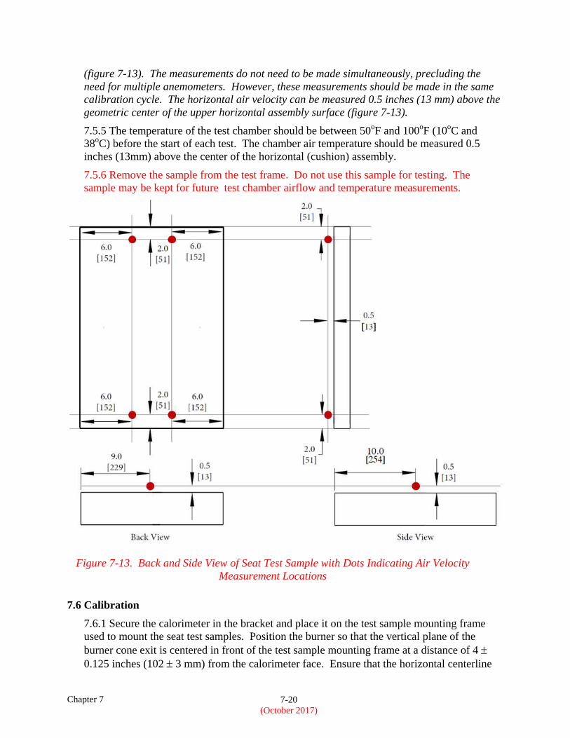
NOTE 4: Although not required, one example of how the language of paragraph 7.5.4 can be
met is by measuring the vertical air velocity at four points. These points are located behind
the vertical (cushion) assembly, 0.5 inches (13 mm) from the rear-facing vertical surface, 2
inches (51 mm) below the vertical assembly top surface, 2 inches (51 mm) above the vertical
assembly bottom surface, and horizontally positioned 6 inches (152 mm) in from each side
Chapter 7 7-20
(October 2017)
(figure 7-13). The measurements do not need to be made simultaneously, precluding the
need for multiple anemometers. However, these measurements should be made in the same
calibration cycle. The horizontal air velocity can be measured 0.5 inches (13 mm) above the
geometric center of the upper horizontal assembly surface (figure 7-13).
7.5.5 The temperature of the test chamber should be between 50oF and 100
oF (10
oC and
38oC) before the start of each test. The chamber air temperature should be measured 0.5
inches (13mm) above the center of the horizontal (cushion) assembly.
7.5.6 Remove the sample from the test frame. Do not use this sample for testing. The
sample may be kept for future test chamber airflow and temperature measurements.
Figure 7-13. Back and Side View of Seat Test Sample with Dots Indicating Air Velocity
Measurement Locations
7.6 Calibration
7.6.1 Secure the calorimeter in the bracket and place it on the test sample mounting frame
used to mount the seat test samples. Position the burner so that the vertical plane of the
burner cone exit is centered in front of the test sample mounting frame at a distance of 4
0.125 inches (102 3 mm) from the calorimeter face. Ensure that the horizontal centerline
Chapter 7 7-21
(October 2017)
of the calorimeter is offset 1 0.0625 inch (25.4 1.6 mm) above the horizontal centerline
of the burner cone (figure 7-7).
7.6.2 Prior to starting the burner, ensure that the calorimeter face is clean of soot deposits and
that there is water running through the calorimeter.
NOTE: Exposing the calorimeter to the burner flame without water running through it will
destroy the calorimeter.
7.6.3 Move the burner away from the test position to the warmup position. Examine and
clean the burner cone of any evidence of buildup of productions of combustion, soot, etc.
NOTE: A stainless steel wire brush is one possible cleaning tool. Soot buildup inside the
burner cone can affect the flame characteristics and cause calibration difficulties. Since the
burner cone may distort with time, dimensions will need to be checked periodically.
7.6.4 While the burner is out of the test position, turn on the fuel and light the burner. Allow
it to warmup for 2 minutes. Move the burner into the test position and adjust the air intake
and oil burner components to achieve a heat flux of 10 Btu/ft2 second or greater (11.36
W/cm2 or greater). Record heat flux density measurements at least once per second averaged
over a 30-second time period to ensure a steady-state condition.
7.6.5 Replace the calorimeter bracket with the thermocouple rake, ensuring that the distance
of each of the seven thermocouples is 4 0.125 inches (102 3 mm) from the vertical exit
plane of the cone and offset 1 0.0625 inch (25.4 1.6 mm) above the horizontal centerline
of the burner cone exit plane (figure 7-8).
7.6.6 Start the burner and allow it to warm up for 2 minutes. After warmup, move the burner
into the test position and allow one minute for thermocouple stabilization, then record the
temperature of each thermocouple at least once every second averaged over a 30-second time
period. Of the seven thermocouples used, any two will be equal to or greater than 1750°F
(954°C), while the remaining thermocouples will each be equal to or greater than 1800°F
(982°C). The average of the seven thermocouples must be equal to or greater than 1800°F.
After a steady-state condition has been achieved with the required temperatures mentioned
above, turn off the burner.
NOTE: It is advisable to run within reasonable bounds of the heat flux and temperature
requirements in sections 7.6.4 and 7.6.6. If the heat flux and temperature are significantly
higher, erratic data may occur.
7.6.7 If the temperature of each thermocouple is not within the specified range, repeat
sections 7.6.1 through 7.6.6 until all parameters are within the calibration range. When
required thermocouple temperatures have been achieved, check that the airflow is within the
required range. Once the parameters are within the specified range, secure the air shutter by
tightening the lock screw.
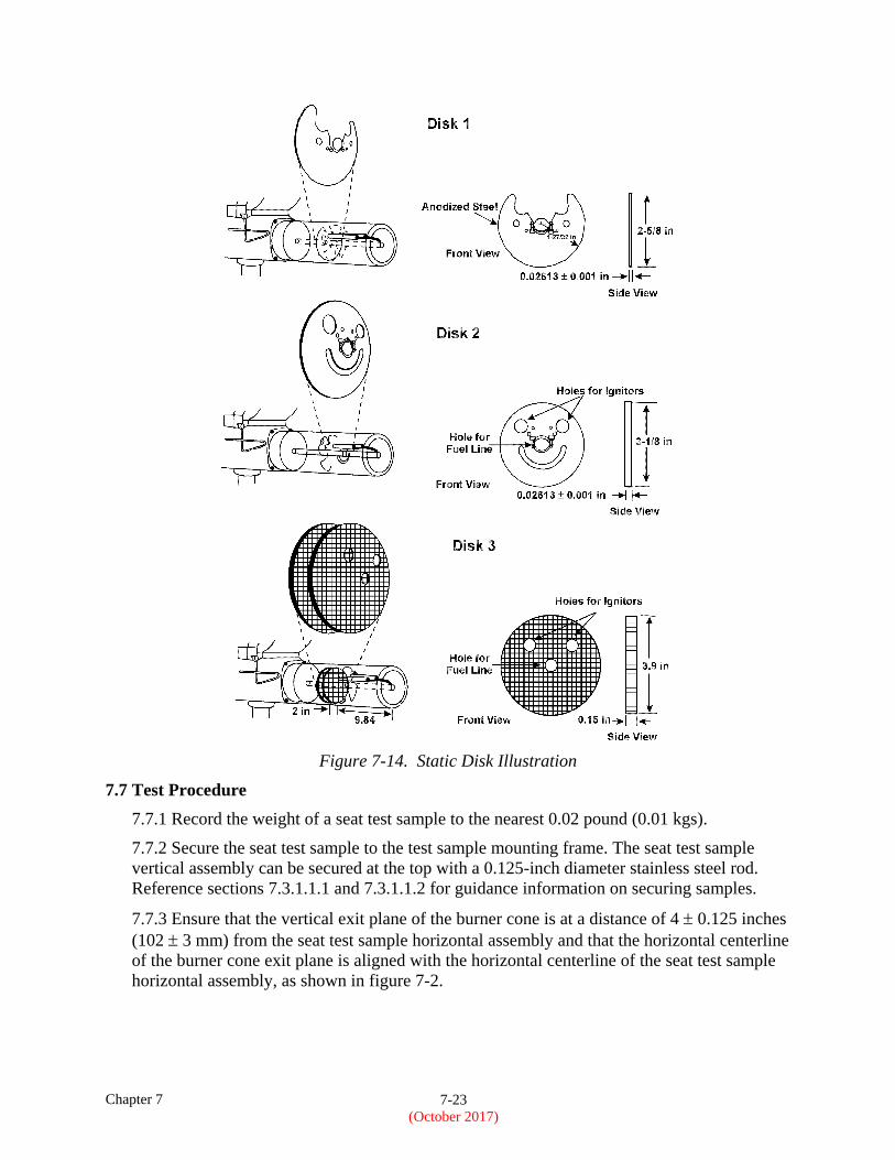
NOTE: Static disks were developed to stabilize the air before entering the combustion area.
Two were designed by Park Oil Burner Manufacturing Company of Atlantic City, New
Jersey. The Park Oil Burner disks are both made of steel (figure 7-14). Disks 1 and 2 are
made for easy assembly, only requiring the removal of the draft tube and installation of the
disk. Disk 3 was developed by CEAT, the French Ministry of Defense. The disk is made of a
Nomex honeycomb material. CEAT uses two honeycomb disks positioned behind the stator.
Chapter 7 7-22
(October 2017)
These disks (any one or more of the three) are an optional feature used to help produce a
more full and even flame. However, there is no guarantee of achieving calibration using a
disk with all of the various makes and models of burners used throughout the industry.
7.6.8 Calibrate the burner prior to each test until consistency has been demonstrated. After
consistency has been confirmed, several tests can be conducted with calibration before and
after each series of tests.
NOTE 1: Recommendations for achieving calibration temperatures and heat flux:
1. Set the stator 3.25 0.25 inches from the end of the draft tube.
2. Rotate the ignitor to the 6 o’clock and 9 o’clock position (viewpoint: looking toward the
stator from the end of the draft tube).
3. Seal all possible air leaks around the burner cone and draft tube area.
4. Install and secure static disk to improve flame characteristics (figure 7-14).
5. Replace thermocouples after 50 hours of use.
NOTE 2: If a sonic type burner is to be used, see Chapter 7 Supplement for “flame validation
procedure” and all test burner information.
Chapter 7 7-23
(October 2017)
Figure 7-14. Static Disk Illustration
7.7 Test Procedure
7.7.1 Record the weight of a seat test sample to the nearest 0.02 pound (0.01 kgs).
7.7.2 Secure the seat test sample to the test sample mounting frame. The seat test sample
vertical assembly can be secured at the top with a 0.125-inch diameter stainless steel rod.
Reference sections 7.3.1.1.1 and 7.3.1.1.2 for guidance information on securing samples.
7.7.3 Ensure that the vertical exit plane of the burner cone is at a distance of 4 0.125 inches
(102 3 mm) from the seat test sample horizontal assembly and that the horizontal centerline
of the burner cone exit plane is aligned with the horizontal centerline of the seat test sample
horizontal assembly, as shown in figure 7-2.
Chapter 7 7-24
(October 2017)
NOTE 1: It is important to ensure the burner cone is aligned to the horizontal assembly when
testing a sample as described in section 7.7.3. The position of the burner relative to the test
sample mounting frame may differ slightly due to dimensional tolerances.
NOTE 2: Dress cover features such as hook and loop closures may protrude beyond the
dress covering material. The additional thickness of such features are not to be included in
the 4 0.125 inch (102 3 mm) distance from the seat test sample horizontal assembly to the
vertical centerline of the burner cone exit plane.
7.7.4 When ready to begin the test, move the burner or test sample apparatus away from the
test position to the warmup position so that the flame will not impinge on the seat test
sample. Turn on and light the burner and allow it to stabilize for 2 minutes.
7.7.5 To begin the test, move the burner or test sample apparatus into the test position and
simultaneously start the timing device when the burner or test sample apparatus is fully in the
test position.
7.7.6 Expose the seat test sample to the burner flame for 2 minutes and then turn off the
burner. Immediately move the burner or test sample apparatus out of the test position.
7.7.7 Terminate the test when the seat test sample self-extinguishes. If the sample does not
self-extinguish after 5 minutes from the time the burner had been turned off, observe and
record the posttest weight of the sample at the 5-minute mark, then terminate the test by
extinguishing the seat test sample.
NOTE: Extinguishing the flame prior to recording the posttest sample weight may alter the
final test weight measurement.
7.7.8 Immediately after test termination, determine the posttest weight of the remains of the
seat test sample to the nearest 0.02 pound (0.01 kg), excluding droppings.
7.7.9 Measure the four burn lengths of the seat test sample.
NOTE: An industry practice acceptable to the FAA for determining cushion assembly burn
length damage has been to use an object with a dull point, such as a pencil, and scrape the
dress covering. If the object used penetrates the dress covering, damage has occurred due to
that area’s combustion. If the dress covering is not penetrated, damage has occurred due to
pyrolysis and is not considered damaged by combustion.
7.8 Report
7.8.1 Identify and describe the seat test sample being tested. Report the type of foam (flame
retardant [FR], molded, or cut); foam density, if known; and manufacturer and type of FR
treatment if known.
7.8.2 Report the number of seat test samples tested.
7.8.3 Report the pretest and posttest weight of each seat test sample, the calculated
percentage weight loss of each seat test sample, and the calculated average percentage weight
for the total number of seat test samples tested.
7.8.4 Report each of the four burn lengths for each seat test sample tested.
Chapter 7 7-25
(October 2017)
7.8.5 Provide a record of burner flame calibration if a Park type burner is used, or flame
temperature validation record if a sonic type burner is used. Specify if a Park or sonic type
burner is used.
NOTE: Although not required, it may be useful to record the date, time, ambient air
temperature, humidity level, and any other data that may be used to study the burn
characteristics of the samples.
7.9 Requirements
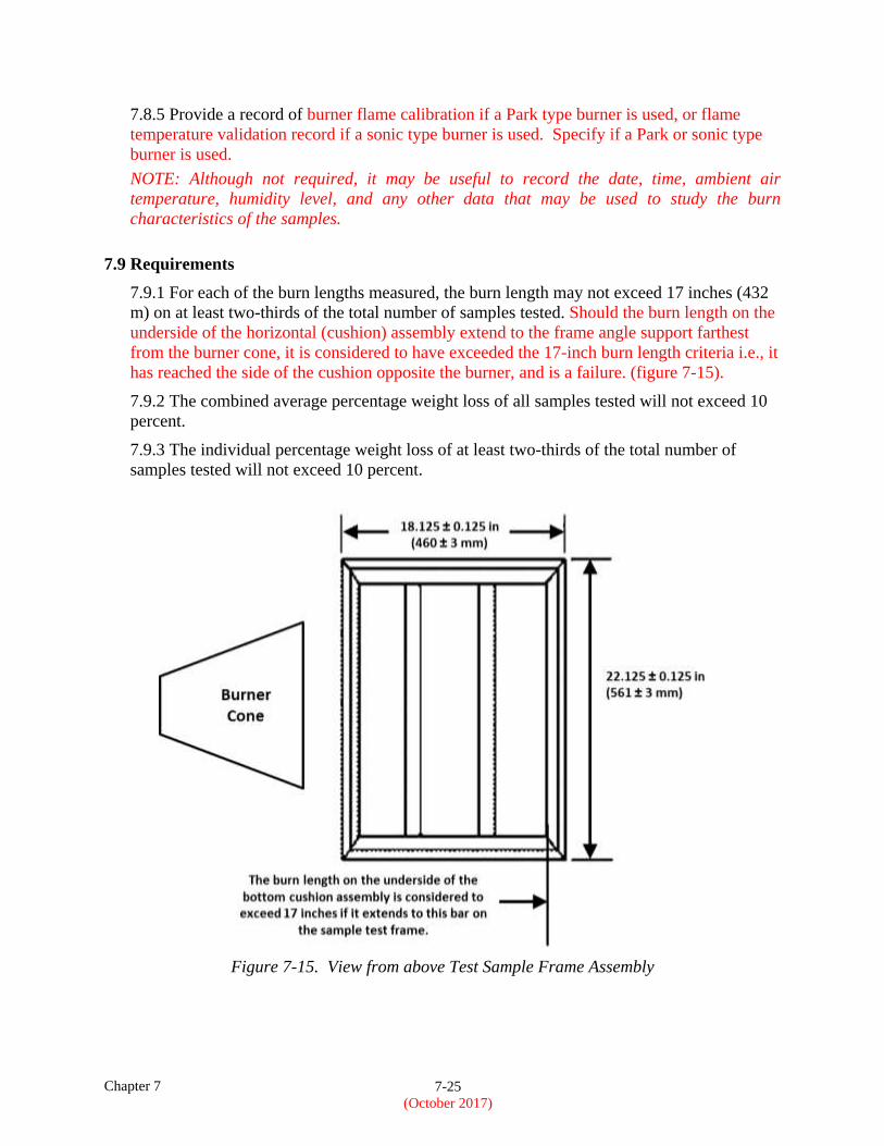
7.9.1 For each of the burn lengths measured, the burn length may not exceed 17 inches (432
m) on at least two-thirds of the total number of samples tested. Should the burn length on the
underside of the horizontal (cushion) assembly extend to the frame angle support farthest
from the burner cone, it is considered to have exceeded the 17-inch burn length criteria i.e., it
has reached the side of the cushion opposite the burner, and is a failure. (figure 7-15).
7.9.2 The combined average percentage weight loss of all samples tested will not exceed 10
percent.
7.9.3 The individual percentage weight loss of at least two-thirds of the total number of
samples tested will not exceed 10 percent.
Figure 7-15. View from above Test Sample Frame Assembly
Chapter 7 Supplement 7-1
(October 2017)
Chapter 7 Supplement
Sonic Burner
Apparatus
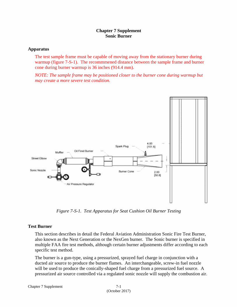
The test sample frame must be capable of moving away from the stationary burner during
warmup (figure 7-S-1). The recommmened distance between the sample frame and burner
cone during burner warmup is 36 inches (914.4 mm).
NOTE: The sample frame may be positioned closer to the burner cone during warmup but
may create a more severe test condition.
Figure 7-S-1. Test Apparatus for Seat Cushion Oil Burner Testing
Test Burner
This section describes in detail the Federal Aviation Administration Sonic Fire Test Burner,
also known as the Next Generation or the NexGen burner. The Sonic burner is specified in
multiple FAA fire test methods, although certain burner adjustments differ according to each
specific test method.
The burner is a gun-type, using a pressurized, sprayed fuel charge in conjunction with a
ducted air source to produce the burner flames. An interchangeable, screw-in fuel nozzle
will be used to produce the conically-shaped fuel charge from a pressurized fuel source. A
pressurized air source controlled via a regulated sonic nozzle will supply the combustion air.
Chapter 7 Supplement 7-2
(October 2017)
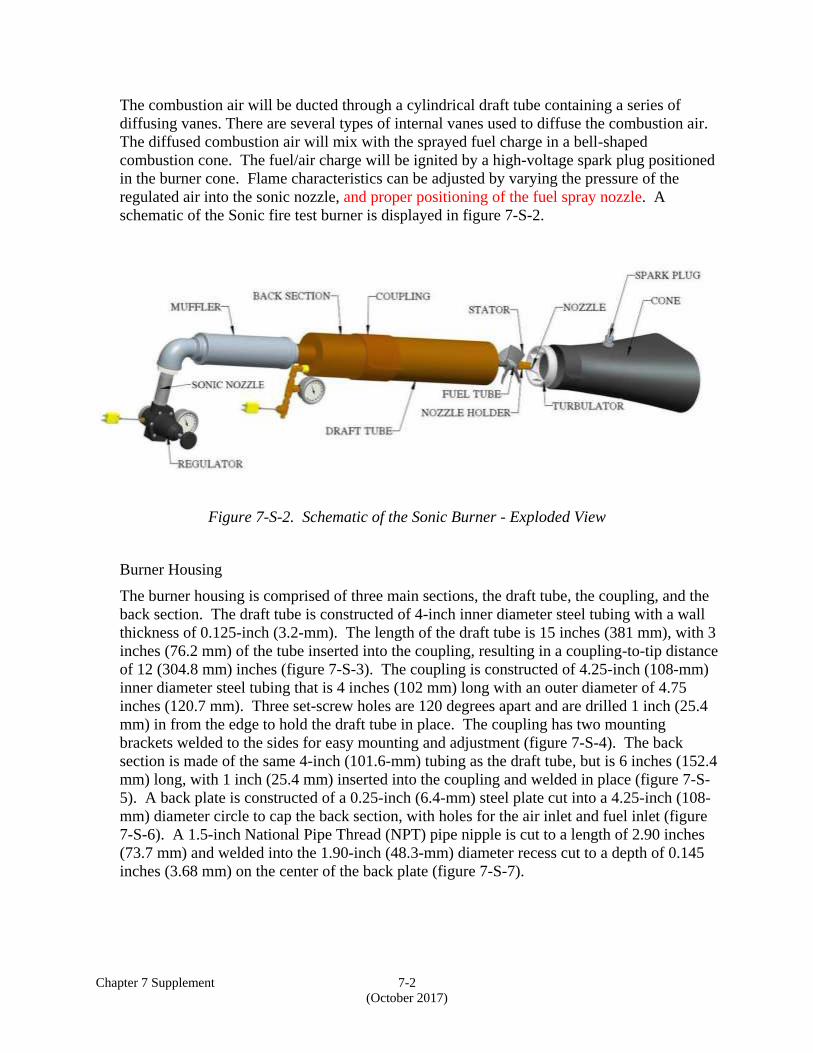
The combustion air will be ducted through a cylindrical draft tube containing a series of
diffusing vanes. There are several types of internal vanes used to diffuse the combustion air.
The diffused combustion air will mix with the sprayed fuel charge in a bell-shaped
combustion cone. The fuel/air charge will be ignited by a high-voltage spark plug positioned
in the burner cone. Flame characteristics can be adjusted by varying the pressure of the
regulated air into the sonic nozzle, and proper positioning of the fuel spray nozzle. A
schematic of the Sonic fire test burner is displayed in figure 7-S-2.
Figure 7-S-2. Schematic of the Sonic Burner - Exploded View
Burner Housing
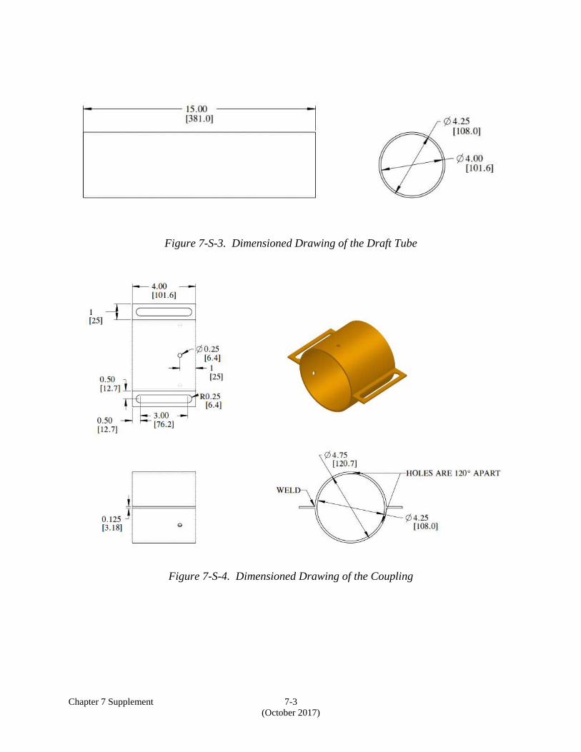
The burner housing is comprised of three main sections, the draft tube, the coupling, and the
back section. The draft tube is constructed of 4-inch inner diameter steel tubing with a wall
thickness of 0.125-inch (3.2-mm). The length of the draft tube is 15 inches (381 mm), with 3
inches (76.2 mm) of the tube inserted into the coupling, resulting in a coupling-to-tip distance
of 12 (304.8 mm) inches (figure 7-S-3). The coupling is constructed of 4.25-inch (108-mm)
inner diameter steel tubing that is 4 inches (102 mm) long with an outer diameter of 4.75
inches (120.7 mm). Three set-screw holes are 120 degrees apart and are drilled 1 inch (25.4
mm) in from the edge to hold the draft tube in place. The coupling has two mounting
brackets welded to the sides for easy mounting and adjustment (figure 7-S-4). The back
section is made of the same 4-inch (101.6-mm) tubing as the draft tube, but is 6 inches (152.4
mm) long, with 1 inch (25.4 mm) inserted into the coupling and welded in place (figure 7-S-
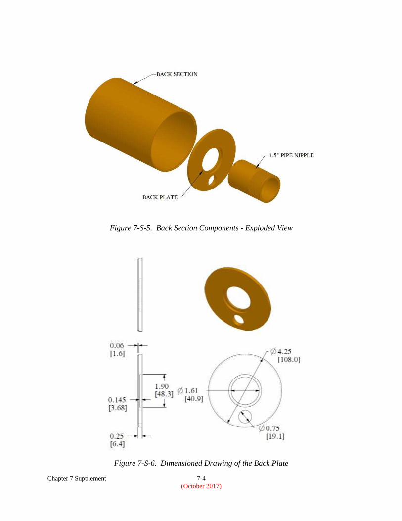
5). A back plate is constructed of a 0.25-inch (6.4-mm) steel plate cut into a 4.25-inch (108-
mm) diameter circle to cap the back section, with holes for the air inlet and fuel inlet (figure
7-S-6). A 1.5-inch National Pipe Thread (NPT) pipe nipple is cut to a length of 2.90 inches
(73.7 mm) and welded into the 1.90-inch (48.3-mm) diameter recess cut to a depth of 0.145
inches (3.68 mm) on the center of the back plate (figure 7-S-7).
Chapter 7 Supplement 7-3
(October 2017)
Figure 7-S-3. Dimensioned Drawing of the Draft Tube
Figure 7-S-4. Dimensioned Drawing of the Coupling
Chapter 7 Supplement 7-4
(October 2017)
Figure 7-S-5. Back Section Components - Exploded View
Figure 7-S-6. Dimensioned Drawing of the Back Plate
Chapter 7 Supplement 7-5
(October 2017)
Figure 7-S-7. Dimensioned Drawing of the Pipe Nipple
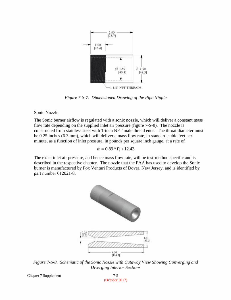
Sonic Nozzle
The Sonic burner airflow is regulated with a sonic nozzle, which will deliver a constant mass
flow rate depending on the supplied inlet air pressure (figure 7-S-8). The nozzle is
constructed from stainless steel with 1-inch NPT male thread ends. The throat diameter must
be 0.25 inches (6.3 mm), which will deliver a mass flow rate, in standard cubic feet per
minute, as a function of inlet pressure, in pounds per square inch gauge, at a rate of
43.12*89.0 iPm
The exact inlet air pressure, and hence mass flow rate, will be test-method specific and is
described in the respective chapter. The nozzle that the FAA has used to develop the Sonic
burner is manufactured by Fox Venturi Products of Dover, New Jersey, and is identified by
part number 612021-8.
Figure 7-S-8. Schematic of the Sonic Nozzle with Cutaway View Showing Converging and
Diverging Interior Sections
Chapter 7 Supplement 7-6
(October 2017)
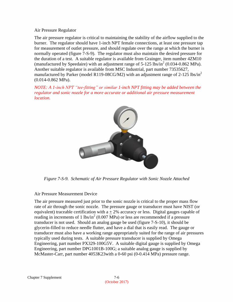
Air Pressure Regulator
The air pressure regulator is critical to maintaining the stability of the airflow supplied to the
burner. The regulator should have 1-inch NPT female connections, at least one pressure tap
for measurement of outlet pressure, and should regulate over the range at which the burner is
normally operated (figure 7-S-9). The regulator must also maintain the desired pressure for
the duration of a test. A suitable regulator is available from Grainger, item number 4ZM10
(manufactured by Speedaire) with an adjustment range of 5-125 lbs/in2 (0.034-0.862 MPa).
Another suitable regulator is available from MSC Industrial, part number 73535627,
manufactured by Parker (model R119-08CG/M2) with an adjustment range of 2-125 lbs/in2
(0.014-0.862 MPa).
NOTE: A 1-inch NPT “tee-fitting” or similar 1-inch NPT fitting may be added between the
regulator and sonic nozzle for a more accurate or additional air pressure measurement
location.
Figure 7-S-9. Schematic of Air Pressure Regulator with Sonic Nozzle Attached
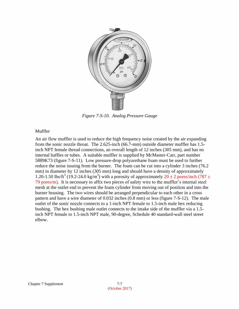
Air Pressure Measurement Device
The air pressure measured just prior to the sonic nozzle is critical to the proper mass flow
rate of air through the sonic nozzle. The pressure gauge or transducer must have NIST (or
equivalent) traceable certification with a + 2% accuracy or less. Digital gauges capable of
reading in increments of 1 lbs/in2 (0.007 MPa) or less are recommended if a pressure
transducer is not used. Should an analog gauge be used (figure 7-S-10), it should be
glycerin-filled to reduce needle flutter, and have a dial that is easily read. The gauge or
transducer must also have a working range appropriately suited for the range of air pressures
typically used during tests. A suitable pressure transducer is supplied by Omega
Engineering, part number PX329-100G5V. A suitable digital gauge is supplied by Omega
Engineering, part number DPG1001B-100G; a suitable analog gauge is supplied by
McMaster-Carr, part number 4053K23with a 0-60 psi (0-0.414 MPa) pressure range.
Chapter 7 Supplement 7-7
(October 2017)
Figure 7-S-10. Analog Pressure Gauge
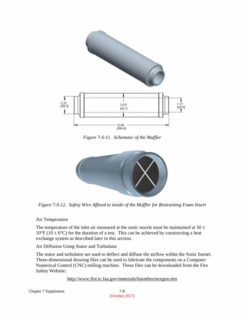
Muffler
An air flow muffler is used to reduce the high frequency noise created by the air expanding
from the sonic nozzle throat. The 2.625-inch (66.7-mm) outside diameter muffler has 1.5-
inch NPT female thread connections, an overall length of 12 inches (305 mm), and has no
internal baffles or tubes. A suitable muffler is supplied by McMaster-Carr, part number
5889K73 (figure 7-S-11). Low pressure-drop polyurethane foam must be used to further
reduce the noise issuing from the burner. The foam can be cut into a cylinder 3 inches (76.2
mm) in diameter by 12 inches (305 mm) long and should have a density of approximately
1.20-1.50 lbs/ft3 (19.2-24.0 kg/m
3) with a porosity of approximately 20 ± 2 pores/inch (787 ±
79 pores/m). It is necessary to affix two pieces of safety wire to the muffler’s internal steel
mesh at the outlet end to prevent the foam cylinder from moving out of position and into the
burner housing. The two wires should be arranged perpendicular to each other in a cross
pattern and have a wire diameter of 0.032 inches (0.8 mm) or less (figure 7-S-12). The male
outlet of the sonic nozzle connects to a 1-inch NPT female to 1.5-inch male hex reducing
bushing. The hex bushing male outlet connects to the intake side of the muffler via a 1.5-
inch NPT female to 1.5-inch NPT male, 90-degree, Schedule 40 standard-wall steel street
elbow.
Chapter 7 Supplement 7-8
(October 2017)
Figure 7-S-11. Schematic of the Muffler
Figure 7-S-12. Safety Wire Affixed to inside of the Muffler for Restraining Foam Insert
Air Temperature
The temperature of the inlet air measured at the sonic nozzle must be maintained at 50 ±
10°F (10 ± 6°C) for the duration of a test. This can be achieved by constructing a heat
exchange system as described later in this section.
Air Diffusion Using Stator and Turbulator
The stator and turbulator are used to deflect and diffuse the airflow within the Sonic burner.
Three-dimensional drawing files can be used to fabricate the components on a Computer
Numerical Control (CNC) milling machine. These files can be downloaded from the Fire
Safety Website:
http://www.fire.tc.faa.gov/materials/burnthru/nexgen.stm
Chapter 7 Supplement 7-9
(October 2017)
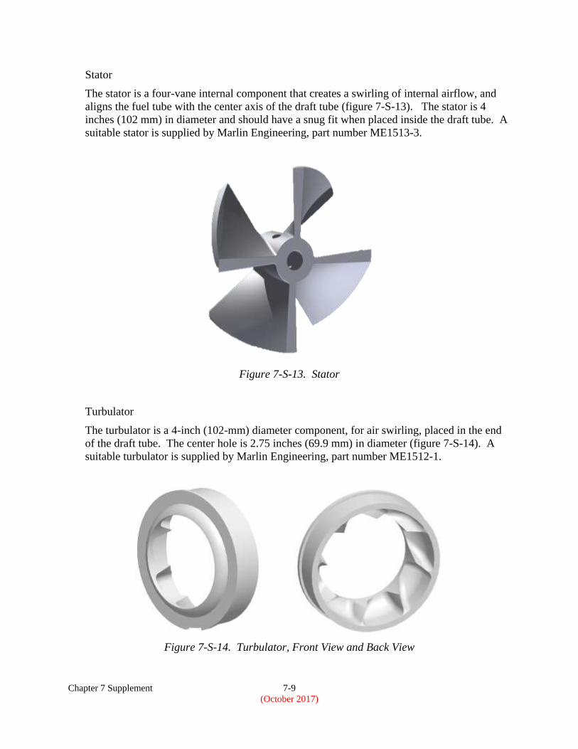
Stator
The stator is a four-vane internal component that creates a swirling of internal airflow, and
aligns the fuel tube with the center axis of the draft tube (figure 7-S-13). The stator is 4
inches (102 mm) in diameter and should have a snug fit when placed inside the draft tube. A
suitable stator is supplied by Marlin Engineering, part number ME1513-3.
Figure 7-S-13. Stator
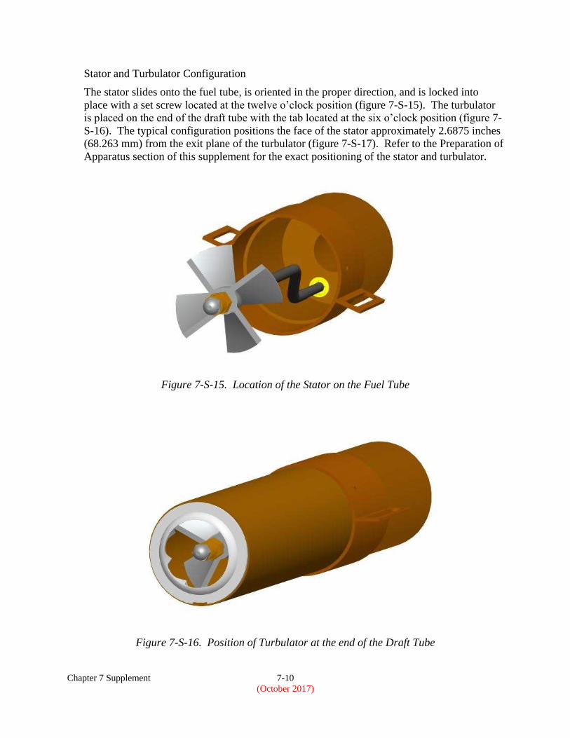
Turbulator
The turbulator is a 4-inch (102-mm) diameter component, for air swirling, placed in the end
of the draft tube. The center hole is 2.75 inches (69.9 mm) in diameter (figure 7-S-14). A
suitable turbulator is supplied by Marlin Engineering, part number ME1512-1.
Figure 7-S-14. Turbulator, Front View and Back View
Chapter 7 Supplement 7-10
(October 2017)
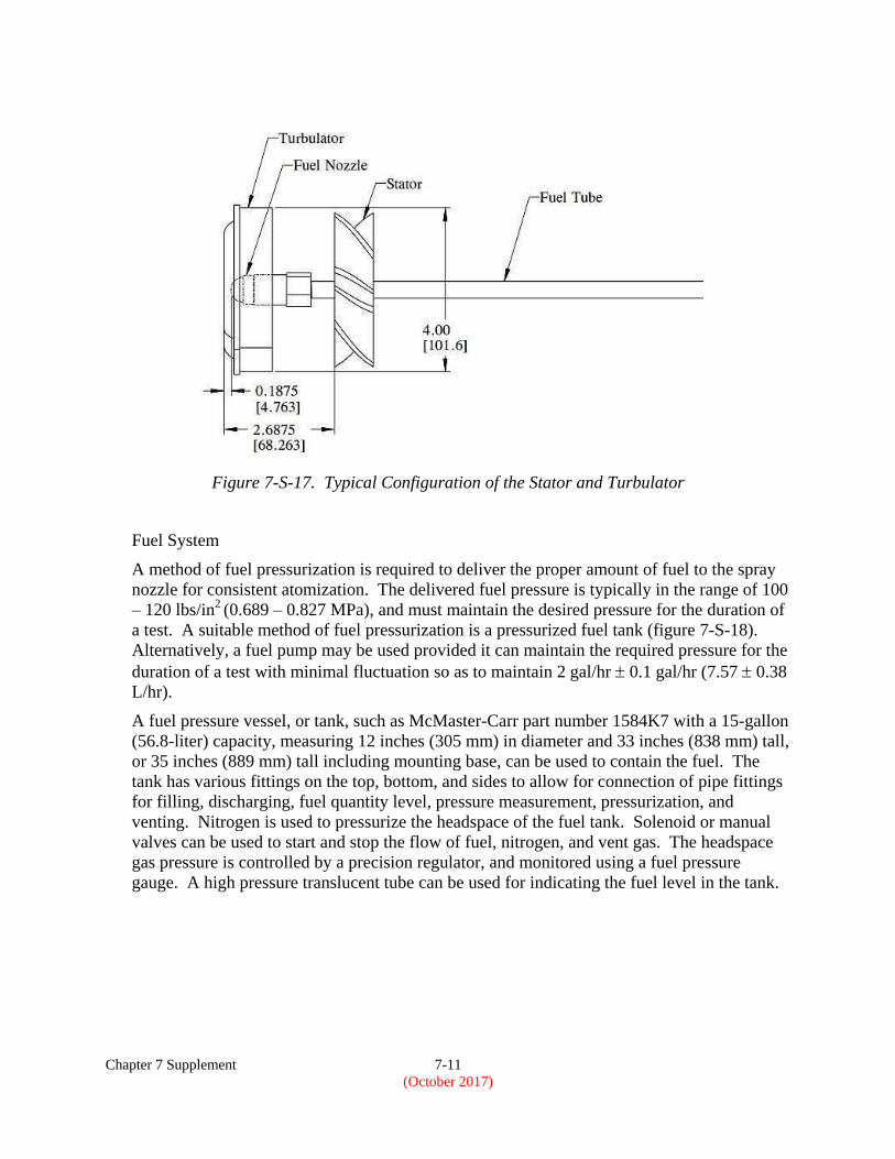
Stator and Turbulator Configuration
The stator slides onto the fuel tube, is oriented in the proper direction, and is locked into
place with a set screw located at the twelve o’clock position (figure 7-S-15). The turbulator
is placed on the end of the draft tube with the tab located at the six o’clock position (figure 7-
S-16). The typical configuration positions the face of the stator approximately 2.6875 inches
(68.263 mm) from the exit plane of the turbulator (figure 7-S-17). Refer to the Preparation of
Apparatus section of this supplement for the exact positioning of the stator and turbulator.
Figure 7-S-15. Location of the Stator on the Fuel Tube
Figure 7-S-16. Position of Turbulator at the end of the Draft Tube
Chapter 7 Supplement 7-11
(October 2017)
Figure 7-S-17. Typical Configuration of the Stator and Turbulator
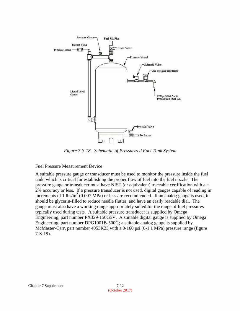
Fuel System
A method of fuel pressurization is required to deliver the proper amount of fuel to the spray
nozzle for consistent atomization. The delivered fuel pressure is typically in the range of 100
– 120 lbs/in2 (0.689 – 0.827 MPa), and must maintain the desired pressure for the duration of
a test. A suitable method of fuel pressurization is a pressurized fuel tank (figure 7-S-18).
Alternatively, a fuel pump may be used provided it can maintain the required pressure for the
duration of a test with minimal fluctuation so as to maintain 2 gal/hr 0.1 gal/hr (7.57 0.38
L/hr).
A fuel pressure vessel, or tank, such as McMaster-Carr part number 1584K7 with a 15-gallon
(56.8-liter) capacity, measuring 12 inches (305 mm) in diameter and 33 inches (838 mm) tall,
or 35 inches (889 mm) tall including mounting base, can be used to contain the fuel. The
tank has various fittings on the top, bottom, and sides to allow for connection of pipe fittings
for filling, discharging, fuel quantity level, pressure measurement, pressurization, and
venting. Nitrogen is used to pressurize the headspace of the fuel tank. Solenoid or manual
valves can be used to start and stop the flow of fuel, nitrogen, and vent gas. The headspace
gas pressure is controlled by a precision regulator, and monitored using a fuel pressure
gauge. A high pressure translucent tube can be used for indicating the fuel level in the tank.
Chapter 7 Supplement 7-12
(October 2017)
Figure 7-S-18. Schematic of Pressurized Fuel Tank System
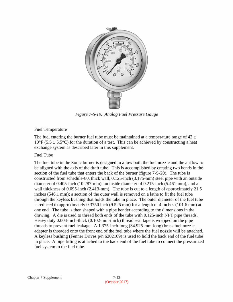
Fuel Pressure Measurement Device
A suitable pressure gauge or transducer must be used to monitor the pressure inside the fuel
tank, which is critical for establishing the proper flow of fuel into the fuel nozzle. The
pressure gauge or transducer must have NIST (or equivalent) traceable certification with a +
2% accuracy or less. If a pressure transducer is not used, digital gauges capable of reading in
increments of 1 lbs/in2 (0.007 MPa) or less are recommended. If an analog gauge is used, it
should be glycerin-filled to reduce needle flutter, and have an easily readable dial. The
gauge must also have a working range appropriately suited for the range of fuel pressures
typically used during tests. A suitable pressure transducer is supplied by Omega
Engineering, part number PX329-150G5V. A suitable digital gauge is supplied by Omega
Engineering, part number DPG1001B-500G; a suitable analog gauge is supplied by
McMaster-Carr, part number 4053K23 with a 0-160 psi (0-1.1 MPa) pressure range (figure
7-S-19).
Chapter 7 Supplement 7-13
(October 2017)
Figure 7-S-19. Analog Fuel Pressure Gauge
Fuel Temperature
The fuel entering the burner fuel tube must be maintained at a temperature range of 42 ±
10°F (5.5 ± 5.5°C) for the duration of a test. This can be achieved by constructing a heat
exchange system as described later in this supplement.
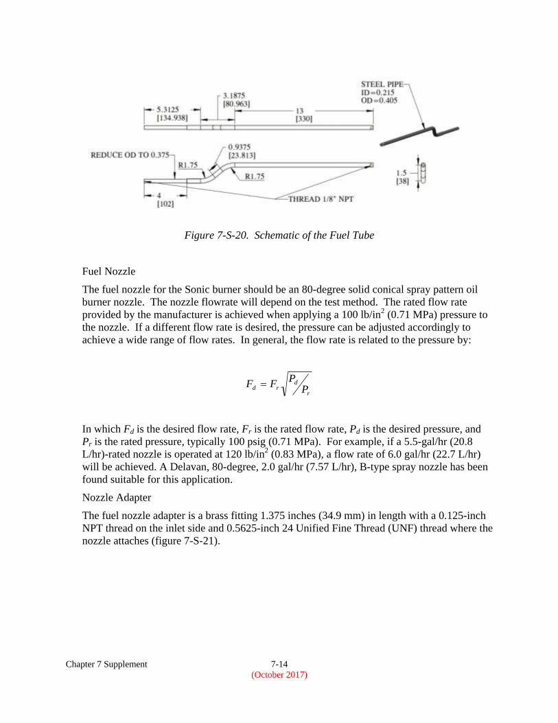
Fuel Tube
The fuel tube in the Sonic burner is designed to allow both the fuel nozzle and the airflow to
be aligned with the axis of the draft tube. This is accomplished by creating two bends in the
section of the fuel tube that enters the back of the burner (figure 7-S-20). The tube is
constructed from schedule-80, thick wall, 0.125-inch (3.175-mm) steel pipe with an outside
diameter of 0.405-inch (10.287-mm), an inside diameter of 0.215-inch (5.461-mm), and a
wall thickness of 0.095-inch (2.413-mm). The tube is cut to a length of approximately 21.5
inches (546.1 mm); a section of the outer wall is removed on a lathe to fit the fuel tube
through the keyless bushing that holds the tube in place. The outer diameter of the fuel tube
is reduced to approximately 0.3750 inch (9.525 mm) for a length of 4 inches (101.6 mm) at
one end. The tube is then shaped with a pipe bender according to the dimensions in the
drawing. A die is used to thread both ends of the tube with 0.125-inch NPT pipe threads.
Heavy duty 0.004-inch-thick (0.102-mm-thick) thread seal tape is wrapped on the pipe
threads to prevent fuel leakage. A 1.375-inch-long (34.925-mm-long) brass fuel nozzle
adapter is threaded onto the front end of the fuel tube where the fuel nozzle will be attached.
A keyless bushing (Fenner Drives p/n 6202109) is used to hold the back end of the fuel tube
in place. A pipe fitting is attached to the back end of the fuel tube to connect the pressurized
fuel system to the fuel tube.
Chapter 7 Supplement 7-14
(October 2017)
Figure 7-S-20. Schematic of the Fuel Tube
Fuel Nozzle
The fuel nozzle for the Sonic burner should be an 80-degree solid conical spray pattern oil
burner nozzle. The nozzle flowrate will depend on the test method. The rated flow rate
provided by the manufacturer is achieved when applying a 100 lb/in2 (0.71 MPa) pressure to
the nozzle. If a different flow rate is desired, the pressure can be adjusted accordingly to
achieve a wide range of flow rates. In general, the flow rate is related to the pressure by:
r
drd P
PFF
In which Fd is the desired flow rate, Fr is the rated flow rate, Pd is the desired pressure, and
Pr is the rated pressure, typically 100 psig (0.71 MPa). For example, if a 5.5-gal/hr (20.8
L/hr)-rated nozzle is operated at 120 lb/in2 (0.83 MPa), a flow rate of 6.0 gal/hr (22.7 L/hr)
will be achieved. A Delavan, 80-degree, 2.0 gal/hr (7.57 L/hr), B-type spray nozzle has been
found suitable for this application.
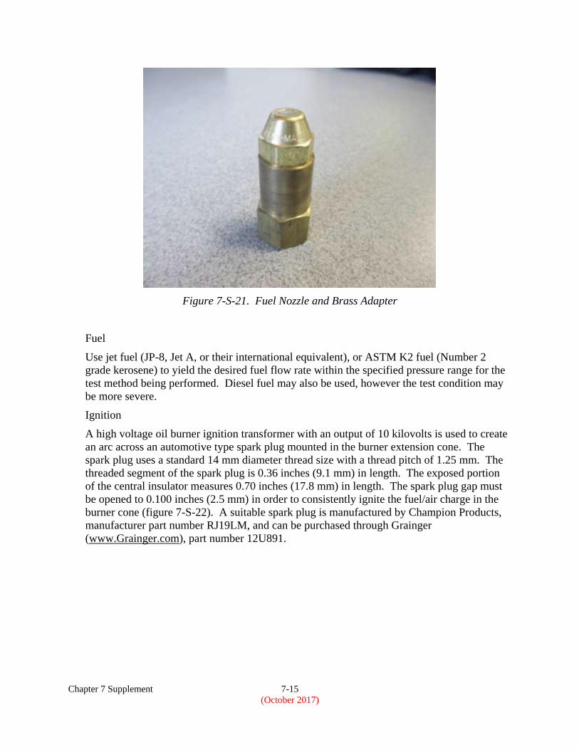
Nozzle Adapter
The fuel nozzle adapter is a brass fitting 1.375 inches (34.9 mm) in length with a 0.125-inch
NPT thread on the inlet side and 0.5625-inch 24 Unified Fine Thread (UNF) thread where the
nozzle attaches (figure 7-S-21).
Chapter 7 Supplement 7-15
(October 2017)
Figure 7-S-21. Fuel Nozzle and Brass Adapter
Fuel
Use jet fuel (JP-8, Jet A, or their international equivalent), or ASTM K2 fuel (Number 2
grade kerosene) to yield the desired fuel flow rate within the specified pressure range for the
test method being performed. Diesel fuel may also be used, however the test condition may
be more severe.
Ignition
A high voltage oil burner ignition transformer with an output of 10 kilovolts is used to create
an arc across an automotive type spark plug mounted in the burner extension cone. The
spark plug uses a standard 14 mm diameter thread size with a thread pitch of 1.25 mm. The
threaded segment of the spark plug is 0.36 inches (9.1 mm) in length. The exposed portion
of the central insulator measures 0.70 inches (17.8 mm) in length. The spark plug gap must
be opened to 0.100 inches (2.5 mm) in order to consistently ignite the fuel/air charge in the
burner cone (figure 7-S-22). A suitable spark plug is manufactured by Champion Products,
manufacturer part number RJ19LM, and can be purchased through Grainger
(www.Grainger.com), part number 12U891.

Chapter 7 Supplement 7-16
(October 2017)
Figure 7-S-22. Dimensioned Drawing of a Spark Plug
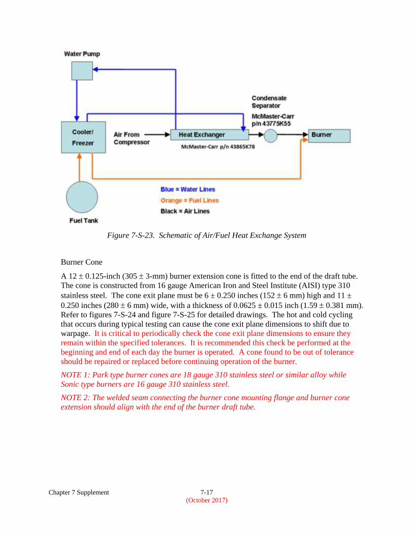
Heat Exchange System
A heat exchange system is used to regulate the temperature of the burner inlet air and fuel as
the flow rate of each is dependent upon the density of the air and fuel. A schematic of a
suitable heat exchange system is displayed in figure 7-S-23. The ice bath can be constructed
from an insulated cooler or a chest freezer with temperature control capability. The fuel
travels through coiled copper tubing in the ice bath and out to the burner. The air is cooled in
a heat exchanger, such as McMaster-Carr part number 43865K78, which has ice water
traveling through the outer shell, removing heat from the air. The ice water is circulated in a
closed-loop from the cooler to the heat exchanger by means of a submersible pump. The
exact dimensions of the copper coils and the flowrate of the water pump will be dependent
upon the particular conditions in the laboratory. Alternate methods such as active heating
and cooling systems can be used, allowing greater precision, but may be more costly.
Chapter 7 Supplement 7-17
(October 2017)
Figure 7-S-23. Schematic of Air/Fuel Heat Exchange System
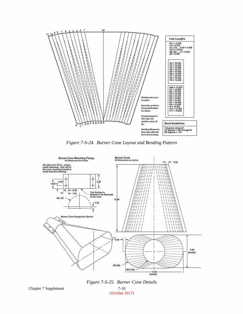
Burner Cone
A 12 0.125-inch (305 3-mm) burner extension cone is fitted to the end of the draft tube.
The cone is constructed from 16 gauge American Iron and Steel Institute (AISI) type 310
stainless steel. The cone exit plane must be 6 ± 0.250 inches (152 6 mm) high and 11 ±
0.250 inches (280 6 mm) wide, with a thickness of 0.0625 ± 0.015 inch (1.59 0.381 mm).
Refer to figures 7-S-24 and figure 7-S-25 for detailed drawings. The hot and cold cycling
that occurs during typical testing can cause the cone exit plane dimensions to shift due to
warpage. It is critical to periodically check the cone exit plane dimensions to ensure they
remain within the specified tolerances. It is recommended this check be performed at the
beginning and end of each day the burner is operated. A cone found to be out of tolerance
should be repaired or replaced before continuing operation of the burner.
NOTE 1: Park type burner cones are 18 gauge 310 stainless steel or similar alloy while
Sonic type burners are 16 gauge 310 stainless steel.
NOTE 2: The welded seam connecting the burner cone mounting flange and burner cone
extension should align with the end of the burner draft tube.
Chapter 7 Supplement 7-18
(October 2017)
Figure 7-S-24. Burner Cone Layout and Bending Pattern
Figure 7-S-25. Burner Cone Details
Chapter 7 Supplement 7-19
(October 2017)
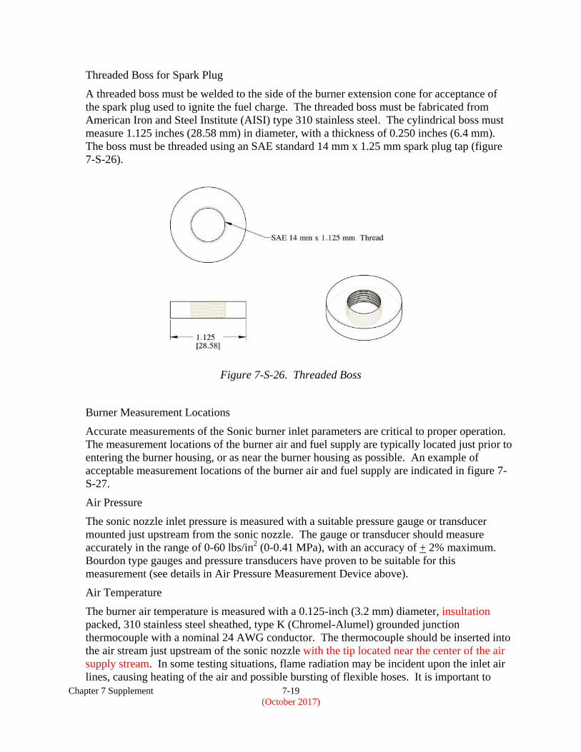
Threaded Boss for Spark Plug
A threaded boss must be welded to the side of the burner extension cone for acceptance of
the spark plug used to ignite the fuel charge. The threaded boss must be fabricated from
American Iron and Steel Institute (AISI) type 310 stainless steel. The cylindrical boss must
measure 1.125 inches (28.58 mm) in diameter, with a thickness of 0.250 inches (6.4 mm).
The boss must be threaded using an SAE standard 14 mm x 1.25 mm spark plug tap (figure
7-S-26).
Figure 7-S-26. Threaded Boss
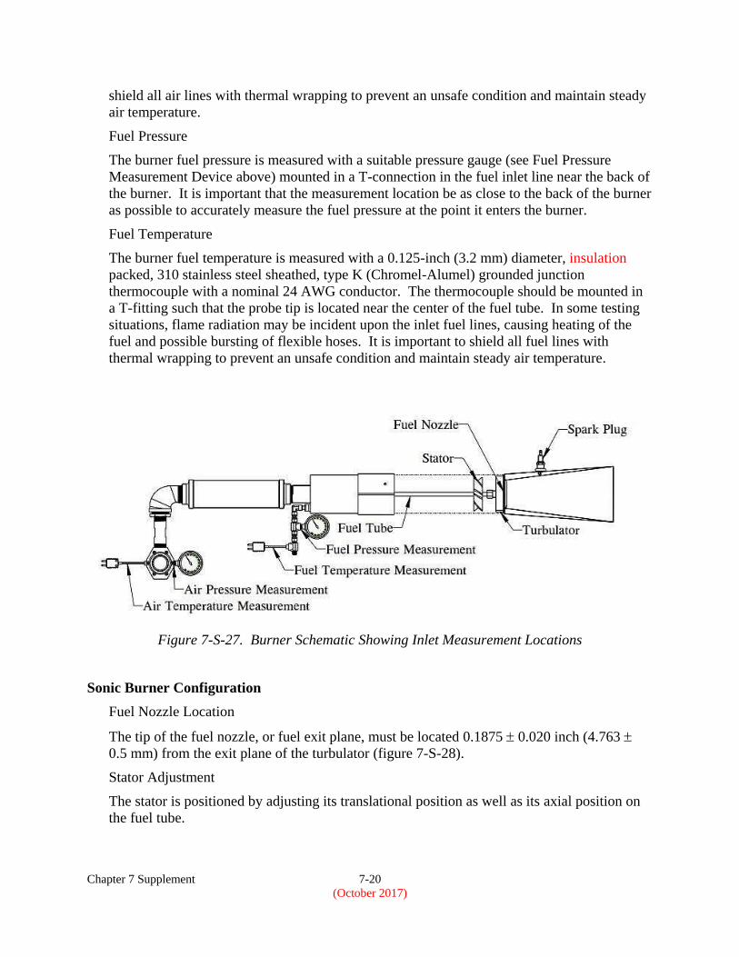
Burner Measurement Locations
Accurate measurements of the Sonic burner inlet parameters are critical to proper operation.
The measurement locations of the burner air and fuel supply are typically located just prior to
entering the burner housing, or as near the burner housing as possible. An example of
acceptable measurement locations of the burner air and fuel supply are indicated in figure 7-
S-27.
Air Pressure
The sonic nozzle inlet pressure is measured with a suitable pressure gauge or transducer
mounted just upstream from the sonic nozzle. The gauge or transducer should measure
accurately in the range of 0-60 lbs/in2 (0-0.41 MPa), with an accuracy of + 2% maximum.
Bourdon type gauges and pressure transducers have proven to be suitable for this
measurement (see details in Air Pressure Measurement Device above).
Air Temperature
The burner air temperature is measured with a 0.125-inch (3.2 mm) diameter, insultation
packed, 310 stainless steel sheathed, type K (Chromel-Alumel) grounded junction
thermocouple with a nominal 24 AWG conductor. The thermocouple should be inserted into
the air stream just upstream of the sonic nozzle with the tip located near the center of the air
supply stream. In some testing situations, flame radiation may be incident upon the inlet air
lines, causing heating of the air and possible bursting of flexible hoses. It is important to
Chapter 7 Supplement 7-20
(October 2017)
shield all air lines with thermal wrapping to prevent an unsafe condition and maintain steady
air temperature.
Fuel Pressure
The burner fuel pressure is measured with a suitable pressure gauge (see Fuel Pressure
Measurement Device above) mounted in a T-connection in the fuel inlet line near the back of
the burner. It is important that the measurement location be as close to the back of the burner
as possible to accurately measure the fuel pressure at the point it enters the burner.
Fuel Temperature
The burner fuel temperature is measured with a 0.125-inch (3.2 mm) diameter, insulation
packed, 310 stainless steel sheathed, type K (Chromel-Alumel) grounded junction
thermocouple with a nominal 24 AWG conductor. The thermocouple should be mounted in
a T-fitting such that the probe tip is located near the center of the fuel tube. In some testing
situations, flame radiation may be incident upon the inlet fuel lines, causing heating of the
fuel and possible bursting of flexible hoses. It is important to shield all fuel lines with
thermal wrapping to prevent an unsafe condition and maintain steady air temperature.
Figure 7-S-27. Burner Schematic Showing Inlet Measurement Locations
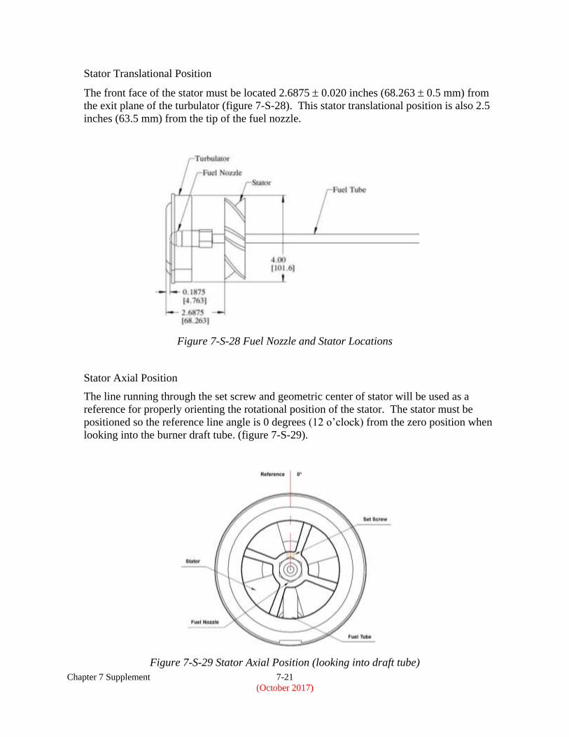
Sonic Burner Configuration
Fuel Nozzle Location
The tip of the fuel nozzle, or fuel exit plane, must be located 0.1875 0.020 inch (4.763
0.5 mm) from the exit plane of the turbulator (figure 7-S-28).
Stator Adjustment
The stator is positioned by adjusting its translational position as well as its axial position on
the fuel tube.
Chapter 7 Supplement 7-21
(October 2017)
Stator Translational Position
The front face of the stator must be located 2.6875 0.020 inches (68.263 0.5 mm) from
the exit plane of the turbulator (figure 7-S-28). This stator translational position is also 2.5
inches (63.5 mm) from the tip of the fuel nozzle.
Figure 7-S-28 Fuel Nozzle and Stator Locations
Stator Axial Position
The line running through the set screw and geometric center of stator will be used as a
reference for properly orienting the rotational position of the stator. The stator must be
positioned so the reference line angle is 0 degrees (12 o’clock) from the zero position when
looking into the burner draft tube. (figure 7-S-29).
Figure 7-S-29 Stator Axial Position (looking into draft tube)
Chapter 7 Supplement 7-22
(October 2017)
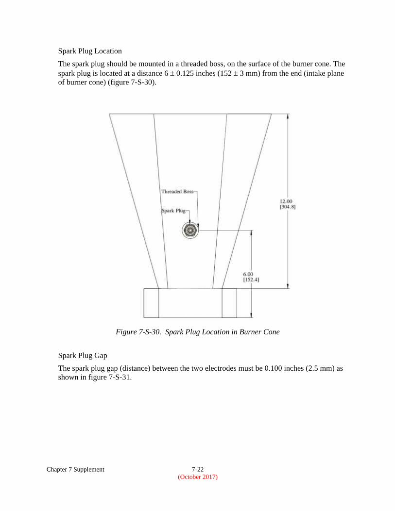
Spark Plug Location
The spark plug should be mounted in a threaded boss, on the surface of the burner cone. The
spark plug is located at a distance 6 0.125 inches (152 3 mm) from the end (intake plane
of burner cone) (figure 7-S-30).
Figure 7-S-30. Spark Plug Location in Burner Cone
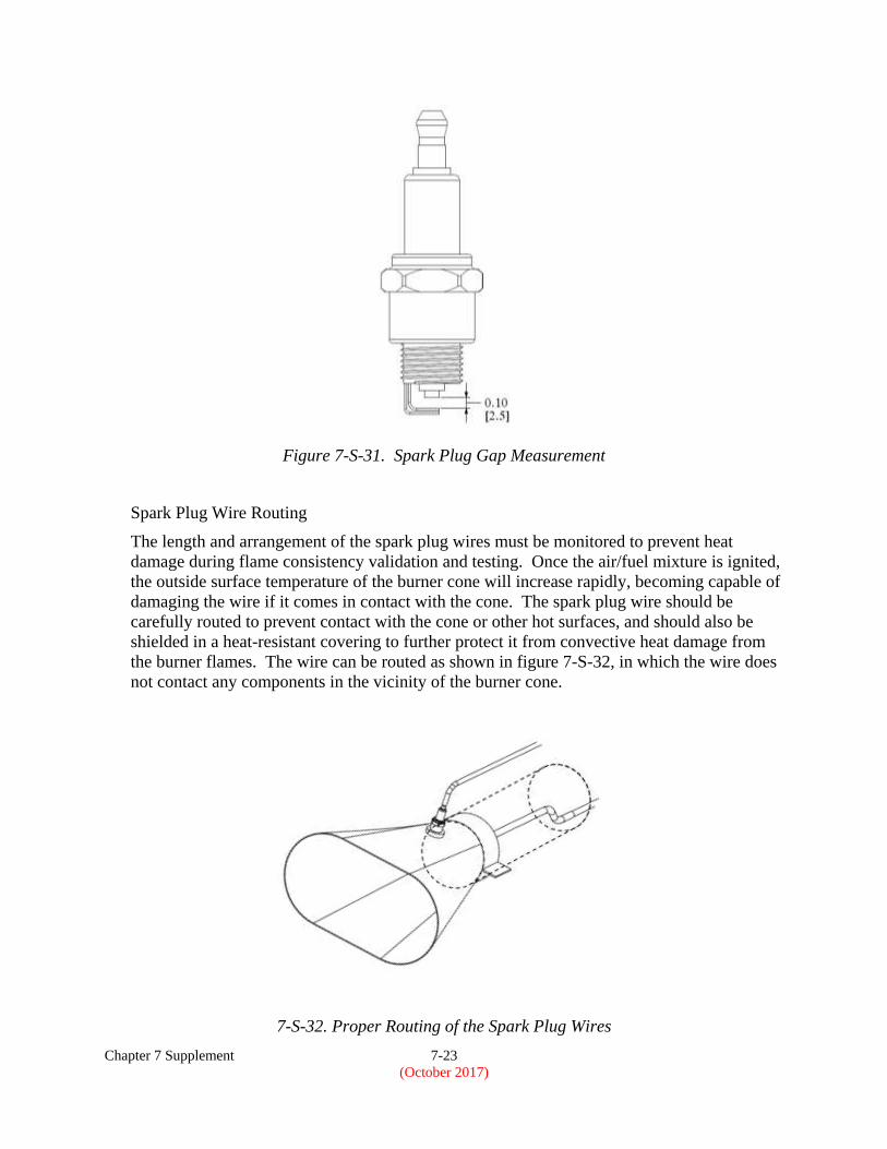
Spark Plug Gap
The spark plug gap (distance) between the two electrodes must be 0.100 inches (2.5 mm) as
shown in figure 7-S-31.
Chapter 7 Supplement 7-23
(October 2017)
Figure 7-S-31. Spark Plug Gap Measurement
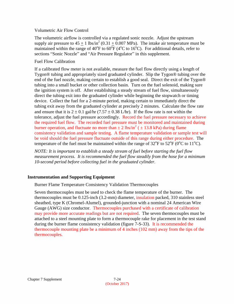
Spark Plug Wire Routing
The length and arrangement of the spark plug wires must be monitored to prevent heat
damage during flame consistency validation and testing. Once the air/fuel mixture is ignited,
the outside surface temperature of the burner cone will increase rapidly, becoming capable of
damaging the wire if it comes in contact with the cone. The spark plug wire should be
carefully routed to prevent contact with the cone or other hot surfaces, and should also be
shielded in a heat-resistant covering to further protect it from convective heat damage from
the burner flames. The wire can be routed as shown in figure 7-S-32, in which the wire does
not contact any components in the vicinity of the burner cone.
7-S-32. Proper Routing of the Spark Plug Wires
Chapter 7 Supplement 7-24
(October 2017)
Volumetric Air Flow Control
The volumetric airflow is controlled via a regulated sonic nozzle. Adjust the upstream
supply air pressure to 45 + 1 lbs/in2 (0.31 + 0.007 MPa). The intake air temperature must be
maintained within the range of 40oF to 60
oF (4
oC to 16
oC). For additional details, refer to
sections “Sonic Nozzle” and “Air Pressure Regulator” in this supplement.
Fuel Flow Calibration
If a calibrated flow meter is not available, measure the fuel flow directly using a length of
Tygon® tubing and appropriately sized graduated cylinder. Slip the Tygon® tubing over the
end of the fuel nozzle, making certain to establish a good seal. Direct the exit of the Tygon®
tubing into a small bucket or other collection basin. Turn on the fuel solenoid, making sure
the ignition system is off. After establishing a steady stream of fuel flow, simultaneously
direct the tubing exit into the graduated cylinder while beginning the stopwatch or timing
device. Collect the fuel for a 2-minute period, making certain to immediately direct the
tubing exit away from the graduated cylinder at precisely 2 minutes. Calculate the flow rate
and ensure that it is 2 0.1 gal/hr (7.57 0.38 L/hr). If the flow rate is not within the
tolerance, adjust the fuel pressure accordingly. Record the fuel pressure necessary to achieve
the required fuel flow. The recorded fuel pressure must be monitored and maintained during
burner operation, and fluctuate no more than ± 2 lbs/in2 ( ± 13.8 kPa) during flame
consistency validation and sample testing. A flame temperature validation or sample test will
be void should the fuel pressure fluctuate outside of this range during either procedure. The
temperature of the fuel must be maintained within the range of 32oF to 52
oF (0
oC to 11
oC).
NOTE: It is important to establish a steady stream of fuel before starting the fuel flow
measurement process. It is recommended the fuel flow steadily from the hose for a minimum
10-second period before collecting fuel in the graduated cylinder.
Instrumentation and Supporting Equipment
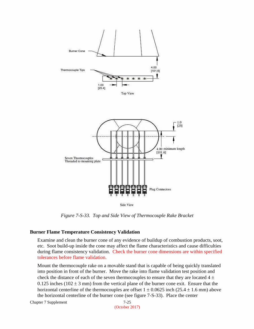
Burner Flame Temperature Consistency Validation Thermocouples
Seven thermocouples must be used to check the flame temperature of the burner. The
thermocouples must be 0.125-inch (3.2-mm) diameter, insulation packed, 310 stainless steel
sheathed, type K (Chromel-Alumel), grounded-junction with a nominal 24 American Wire
Gauge (AWG) size conductor. Thermocouples purchased with a certificate of calibration
may provide more accurate readings but are not required. The seven thermocouples must be
attached to a steel mounting plate to form a thermocouple rake for placement in the test stand
during the burner flame consistency validation (figure 7-S-33). It is recommended the
thermocouple mounting plate be a minimum of 4 inches (102 mm) away from the tips of the
thermocouples.
Chapter 7 Supplement 7-25
(October 2017)
Figure 7-S-33. Top and Side View of Thermocouple Rake Bracket
Burner Flame Temperature Consistency Validation
Examine and clean the burner cone of any evidence of buildup of combustion products, soot,
etc. Soot build-up inside the cone may affect the flame characteristics and cause difficulties
during flame consistency validation. Check the burner cone dimensions are within specified
tolerances before flame validation.
Mount the thermocouple rake on a movable stand that is capable of being quickly translated
into position in front of the burner. Move the rake into flame validation test position and
check the distance of each of the seven thermocouples to ensure that they are located 4
0.125 inches (102 3 mm) from the vertical plane of the burner cone exit. Ensure that the
horizontal centerline of the thermocouples are offset 1 0.0625 inch (25.4 1.6 mm) above
the horizontal centerline of the burner cone (see figure 7-S-33). Place the center
Chapter 7 Supplement 7-26
(October 2017)
thermocouple (thermocouple number 4) in front of the vertical centerline of the burner cone
exit. Note that the thermocouple rake movable stand must incorporate detents that ensure
proper centering of the thermocouple rake with respect to the burner cone, so that rapid
positioning of the rake can be achieved during the validation procedure. Once the proper
position is established, move the thermocouple rake away, and move back into the validation
position to re-check distances. When all distances and positions are confirmed, move the
thermocouple rake away from burner.
While the thermocouple rake is away from the burner, turn on the spark plug, pressurized air
and fuel flow, and light the burner. Allow the burner to warm up for a period of 2 minutes.
After warm-up, move the thermocouple rake into position and allow 1 minute for
thermocouple stabilization, then record the temperature of each of the seven thermocouples
once every second for a period of 30 seconds. Remove the thermocouple rake from flame
temperature validation position and turn off burner. Calculate the average temperature of
each thermocouple over this period and record. Although not a requirement for testing, the
recommended average temperature of each of the seven thermocouples should be 1700°F +
100°F (927°C + 55°C). The burner should be rechecked to ensure it is configured properly if
temperatures are measured outside of this recommended range. A flame that appears biased
to one side, or produces significantly higher temperatures on one end of the flame validation
thermocouple rake, may indicate an adjustment of the fuel nozzle and/or internal stator
orientation and/or distance from the end of the draft tube may be necessary, provided the
adjustments are within allowable tolerances. If no problems are found with the burner, any
thermocouple reading outside of this range may require replacement. It is recommended that
the burner flame temperature be validated at the beginning and end of each day testing is
performed.
NOTE 1: The thermocouples are subjected to high temperature durations during calibration.
Because of this type of cycling, the thermocouples may degrade with time. Small but
continuing decreases or extreme variations in temperature or “no” temperature reading at
all are signs that the thermocouple or thermocouples are degrading or open circuits have
occurred. In this case, the thermocouple or thermocouples should be replaced in order to
maintain accuracy in calibrating the burner. It is recommended that a record be kept for the
amount of time the thermocouples are exposed to the oil burner’s flame.
NOTE 2: The Sonic burner is sensitive to proper alignment of the fuel nozzle. It is crucial
that the fuel nozzle be aligned to the geometric center of the turbulator. A slight adjustment
of the fuel tube between the stator and fuel nozzle may be required to obtain an even
temperature profile across the thermocouple rake. The center point of the nozzle where the
fuel exits should not deviate more than 0.0625 inches from the geometric center of the
turbulator exit plane when looking into the burner draft tube. This should be performed only
after checking the burner for proper configuration.