Embed Size (px)
Citation preview

Chapter 7
Chapter 7: Geometrical Optics
7.1 Reflection at a Spherical Surface
L.O 7.1.1 State laws of reflection
L.O 7.1.2 Sketch and use ray diagrams to determine the characteristics of image
formed by spherical mirrors
L.O 7.1.3 Use
for real object only
A spherical mirror is a reflecting surface with spherical geometry.
Two types:
i. Convex, if the reflection takes place on the outer surface of the spherical shape.
ii. Concave, if the reflecting surface is on the inner surface of the sphere.
C : centre of curvature of the surface mirror.
P : centre of the surface mirror (vertex or pole).
Line CP : principal or optical axis.
AB : aperture of the mirror.
F : focal point of the mirror.
f : focal length (FP, distance between focal point and the centre of the mirror).
r : radius of curvature of the mirror.
Laws of reflection state:
The incident ray, the reflected ray and the
normal all lie in the same plane.
The angle of incidence, i equal the angle
of reflection, r as shown in figure below.

Chapter 7
Ray diagrams for spherical mirrors:
Ray diagram is defined as the simple graphical method to indicate the positions of the
object and image in a system of mirrors or lenses.
Table below shows the conditions for ray diagram:
Ray 1 Ray 2 Ray 3
A ray parallel to the
principal axis passes
through or diverges from
the focal point F after
reflection.
A ray which passes through or
is directed towards the focal
point F is reflected as a ray
parallel to the principal axis.
A ray which passes through or
is directed towards the centre
of curvature C will be
reflected back along the same
path.
At least any
two rays for
drawing the
ray diagram.

Chapter 7
Concave Mirror
Object
Distance u
Ray Diagram Image Property
u > r
Real
Inverted
Diminished
Between point C and F
u = r
Real
Inverted
Same size
Formed at point C
(Application: Overhead
projector)
f < u < r
Real
Inverted
Magnified
Formed at a distance
greater than C
u = f
Real or virtual
Formed at infinity
(Application: Torchlight, car
spotlight)
u < f
Virtual
Upright
Magnified
Formed at the back of
the mirror
(Application: Make-up
mirror, shaving mirror,
mirror used by dentist)

Chapter 7
u at
infinity
Real
Inverted
Diminished
Formed at point F
(Application: Reflection
telescope)
Convex Mirror
Object
Distance u
Ray Diagram Image Property
Any position
in front of
the convex
mirror
Virtual
Upright
Diminished
Formed at the back of
mirror
(Application: rear-mirror and
side-mirrors of cars, at sharp
corners of a road, and the
corners in a supermarket
because it has a wide field of
view and providing an
upright image.)
Equation (formula) of spherical mirror:
vuf
111
Relationship between focal length, f and radius of curvature, r:
ΔFCM is isosceles (FC = FM).
Consider ray AM is paraxial (parallel
and very close to the principal axis).
2
CP2
1FP
FP FM
rf
For spherical
mirror only

Chapter 7
Linear magnification of the spherical mirror, m is defined as the ratio between image height,
hi and object height, ho.
u
v
h
hm i
0
m is a positive value if the image formed is upright and it is negative if the image formed is
inverted.
Table below shows the sign convention for spherical mirror’s equation:
Physical Quantity Positive sign (+) Negative sign (-)
Object Distance, u Real object
(in front of the mirror)
Virtual object
(at the back of the mirror)
Image Distance, v Real image
(same side of the object)
Virtual image
(Opposite side of the object)
Focal length, f Concave mirror Convex mirror
Linear magnification, m Upright image Inverted image
Object/ Image Height, h Upright image Inverted image
Note:
Real image is formed by the actual light rays that pass through the image.
Real image can be projected on the screen.
Example
Question Solution
A dentist uses a small mirror attached to a
thin rod to examine one of your teeth. When
the tooth is 1.20 cm in front of the mirror, the
image it forms is 9.25 cm behind the mirror.
Determine
a. the focal length of the mirror and state
the type of the mirror used
b. the magnification of the image

Chapter 7
Question Solution
An upright image is formed 20.5 cm from the
real object by using the spherical mirror. The
image’s height is one fourth of object’s
height.
a. Where should the mirror be placed
relative to the object?
b. Calculate the radius of curvature of the
mirror and describe the type of mirror
required.
c. Sketch and label a ray diagram to show
the formation of the image
A mirror on the passenger side of your car is
convex and has a radius of curvature 20.0
cm. Another car is seen in this side mirror
and is 11.0 m in front of the mirror (behind
your car). If this car is 1.5 m tall, calculate
the height of the car image.
A person of 1.60 m height stands 0.60 m
from a surface of a hanging shiny globe in a
garden.
a. If the diameter of the globe is 18 cm,
where is the image of the
b. person relative to the surface of the
globe?
c. How tall is the person’s image?
d. State the characteristics of the person’s
image.

Chapter 7
Exercise
Question
An object is placed 10 cm in front of a concave mirror whose focal length is 15 cm.
Determine
a. the position of the image.
b. the linear magnification and state the properties of the image.
Answer: v = ‒30 cm; m = 3
A concave mirror forms an image on a wall 3.20 m from the mirror of the filament of a
headlight lamp. If the height of the filament is 5.0 mm and the height of its image is 35.0 cm,
calculate
a. the position of the filament from the pole of the mirror.
b. the radius of curvature of the mirror.
Answer: 4.57 cm; 9.01 cm
a. A concave mirror forms an inverted image four times larger than the object. Find the
focal length of the mirror, assuming the distance between object and image is 0.600 m.
b. A convex mirror forms a virtual image half the size of the object. Assuming the distance
between image and object is 20.0 cm, determine the radius of curvature of the mirror.
Answer : 160 mm, -267 mm
If a concave mirror has a focal length of 10 cm, find the two positions where an object can
be placed to give, in each case, an image twice the height of the object.
Answer: 15 cm, 5.0 cm
A convex mirror of radius of curvature 40 cm forms an image which is half the height of the
object. Find the object and image position.
Answer: 20 cm, 10 cm behind the mirror
A 1.74 m tall shopper in a department store is 5.19 m from a security mirror. The shopper
notices that his image in the mirror appears to be only 16.3 cm tall.
a. Is the shopper’s image upright or inverted? Explain.
b. Determine the radius of curvature of the mirror.
Answer: u think, 1.07 m
A concave mirror of a focal length 36 cm produces an image whose distance from the mirror
is one third of the object distance. Calculate the object and image distances.
Asnwer: 144 cm, 48 cm
Chapter 7
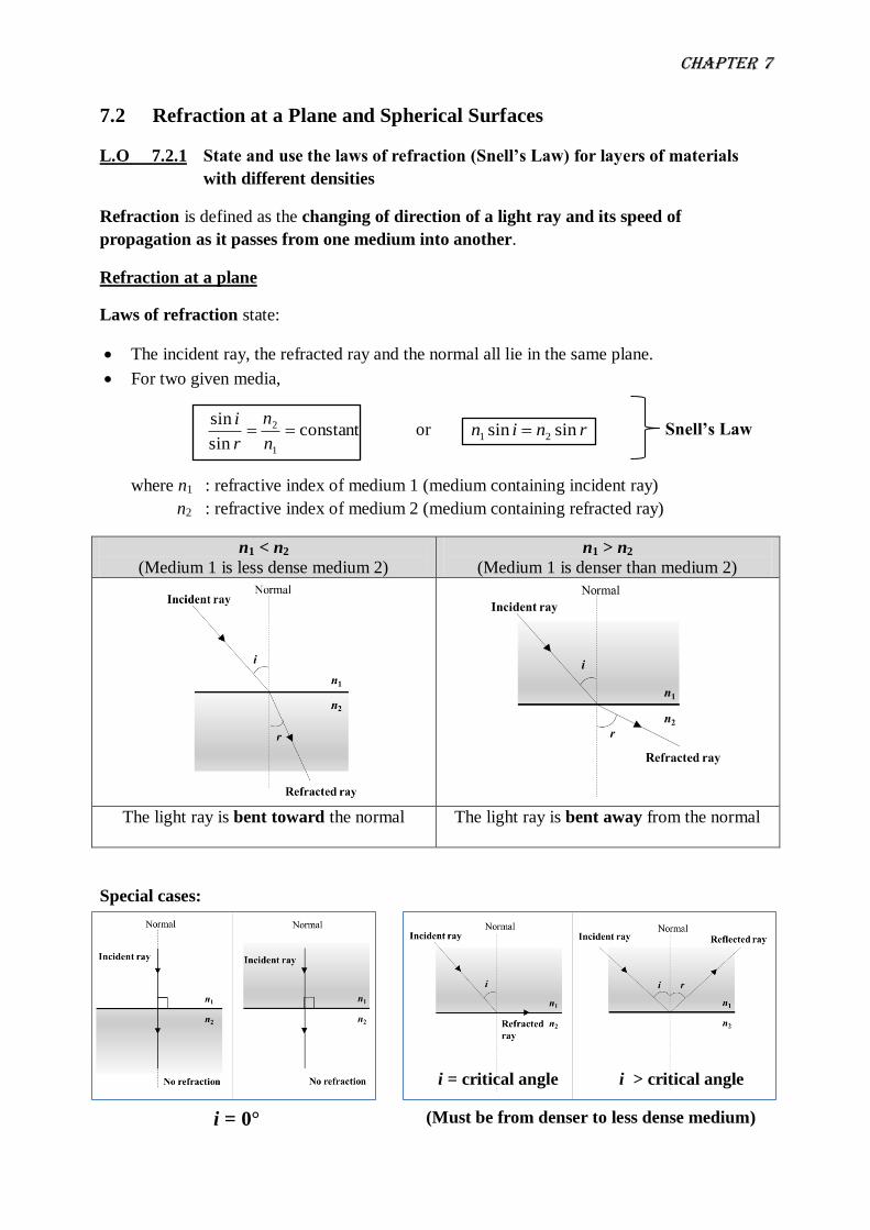
7.2 Refraction at a Plane and Spherical Surfaces
L.O 7.2.1 State and use the laws of refraction (Snell’s Law) for layers of materials
with different densities
Refraction is defined as the changing of direction of a light ray and its speed of
propagation as it passes from one medium into another.
Refraction at a plane
Laws of refraction state:
The incident ray, the refracted ray and the normal all lie in the same plane.
For two given media,
constant sin
sin
1
2 n
n
r
i or rnin sin sin 21
where n1 : refractive index of medium 1 (medium containing incident ray)
n2 : refractive index of medium 2 (medium containing refracted ray)
n1 < n2
(Medium 1 is less dense medium 2)
n1 > n2
(Medium 1 is denser than medium 2)
The light ray is bent toward the normal
The light ray is bent away from the normal
Special cases:
Snell’s Law
i = 0°
i = critical angle i > critical angle
(Must be from denser to less dense medium)

Chapter 7
Refractive index (index of refraction)
Definition – is defined as the constant ratio r
i
sin
sin for the two given media.
The value of refractive index depends on the type of medium and the colour of the light.
It is dimensionless and its value greater than 1.
Consider the light ray travels from medium 1 into medium 2, the refractive index can be
denoted by
If medium 1 is vacuum, then the refractive index is called absolute refractive index,
written as:
v
cn
mediumin light ofvelocity
in vacuumlight ofvelocity
Relationship between refractive index and the wavelength of light:
As light travels from one medium to another, its wavelength, changes but its frequency,
f remains constant.
The wavelength changes because of different material. The frequency remains constant
because the number of wave cycles arriving per unit time must equal the number
leaving per unit time so that the boundary surface cannot create or destroy waves.
By considering a light travels from medium 1 (n1) into medium 2 (n2), the velocity of light
in each medium is given by
11 fv and 22 fv
The refractive index can be written as:
0
mediumin light of wavelength
in vacuumlight of wavelengthn
Other equation for absolute refractive index
in term of depth is given by
depthapparent
depth realn
(Medium containing
the incident ray) (Medium containing
the refracted ray)
2
121
2 mediumin light ofvelocity
1 mediumin light ofvelocity
v
vn

Chapter 7
L.O 7.2.2 Use
for spherical surface
Equation of spherical refracting surface:
r
nn
v
n
u
n 1221
Table below shows the sign convention for spherical refracting surface’s equation:
Physical Quantity Positive sign (+) Negative sign (-)
Object Distance, u Real object
(the object is on the same side of the
spherical surface from where the light
is coming)
Virtual object
(the object is on the opposite side of
the spherical surface from where the
light is coming)
Image Distance, v Real image
(the image is on the opposite side of
the spherical surface from where the
light is coming)
Virtual image
(the image is on the same side of the
spherical surface from where the light
is coming)
Radius of
curvature, r
Convex surface
(the center of curvature is on the the
opposite side of the spherical surface
from where the light is coming)
Concave surface
(the center of curvature is on the the
same side of the spherical surface
from where the light is coming)
If the refraction surface is flat (plane), r = ∞
The equation (formula) of linear magnification for refraction by the spherical surface is
given by
un
vn
h
hm
o
i
2
1

Chapter 7
Example
Question Solution
A fifty cent coin is at the bottom of a
swimming pool of depth 3.00 m. The refractive
index of air and water are 1.00 and 1.33
respectively. Determine the apparent depth of
the coin.
A cylindrical glass rod in air has a refractive
index of 1.52. One end is ground to a
hemispherical surface with radius, r = 3.00 cm
as shown in figure below.
Calculate,
a. the position of the image for a small object
on the axis of the rod, 10.0 cm to the left of
the pole as shown in figure.
b. the linear magnification.
(Given the refractive index of air , na= 1.00)
Figure below shows an object O placed at a
distance 20.0 cm from the surface P of a glass
sphere of radius 5.0 cm and refractive index of
1.63.
Chapter 7
Exercise
Question
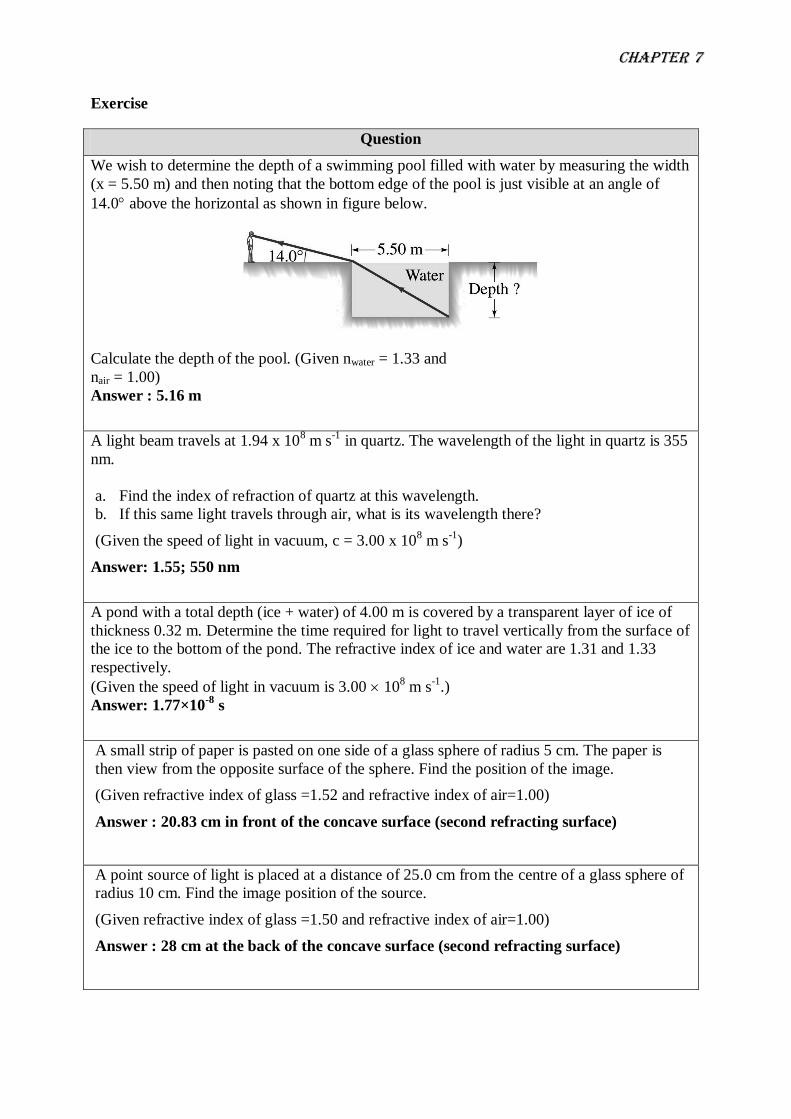
We wish to determine the depth of a swimming pool filled with water by measuring the width
(x = 5.50 m) and then noting that the bottom edge of the pool is just visible at an angle of
14.0 above the horizontal as shown in figure below.
Calculate the depth of the pool. (Given nwater = 1.33 and
nair = 1.00)
Answer : 5.16 m
A light beam travels at 1.94 x 10⁸ m s
-1 in quartz. The wavelength of the light in quartz is 355
nm.
a. Find the index of refraction of quartz at this wavelength.
b. If this same light travels through air, what is its wavelength there?
(Given the speed of light in vacuum, c = 3.00 x 10⁸ m s
-1)
Answer: 1.55; 550 nm
A pond with a total depth (ice + water) of 4.00 m is covered by a transparent layer of ice of
thickness 0.32 m. Determine the time required for light to travel vertically from the surface of
the ice to the bottom of the pond. The refractive index of ice and water are 1.31 and 1.33
respectively.
(Given the speed of light in vacuum is 3.00 108 m s
-1.)
Answer: 1.77×10⁻⁸
s
A small strip of paper is pasted on one side of a glass sphere of radius 5 cm. The paper is
then view from the opposite surface of the sphere. Find the position of the image.
(Given refractive index of glass =1.52 and refractive index of air=1.00)
Answer : 20.83 cm in front of the concave surface (second refracting surface)
A point source of light is placed at a distance of 25.0 cm from the centre of a glass sphere of
radius 10 cm. Find the image position of the source.
(Given refractive index of glass =1.50 and refractive index of air=1.00)
Answer : 28 cm at the back of the concave surface (second refracting surface)

Chapter 7
7.3 Thin lenses
L.O 7.3.1 Sketch and use ray diagrams to determine the characteristic of image
formed by concave and convex lenses
Thin lens is defined as a transparent material with two spherical refracting surfaces whose
thickness is thin compared to the radii of curvature of the two refracting surfaces.
Thin lenses are divided into two types:
i. Convex (Converging) lens which are thicker at the centre than the edges
ii. Concave (Diverging) lens which are thinner at the centre then at the edges
Both convex and concave lenses have two refractive surfaces of radii of curvature r1 and r2
with their respective centre of curvatures at C1 and C2:
Centre of curvature (point C1 and C2) is defined as the centre of the sphere of which
the surface of the lens is a part.
Radius of curvature (r1 and r2) is defined as the radius of the sphere of which the
surface of the lens is a part.
Principal (Optical) axis is defined as the line joining the two centres of curvature of a
lens.
Optical centre (point O) is defined as the point at which any rays entering the lens
pass without deviation.

Chapter 7
Table below shows the conditions for ray diagram:
Ray 1 Ray 2 Ray 3
Ray which is parallel to the
principal axis will be
deflected by the lens towards/
away from the focal point F.
Ray passing through the
optical centre is un-deflected.
Ray which passes through the
focal point (convex lens) or
appear to converge to the
focal point (concave lens)
becomes parallel to the
principal axis after emerging
from lens.
At least any
two rays for
drawing the
ray diagram.

Chapter 7
Converging Lens
Object
Distance u
Ray Diagram Image Property
u > 2f
Real
Inverted
Diminished
Between F2 and 2F2 at the
back of the lens
(Application: Camera lens,
human eye lens)
u = 2f
Real
Inverted
Same size
Formed at point 2F2 at
the back of the lens
(Application: Photocopier)
f < u < 2f
Real
Inverted
Magnified
Formed at a distance
greater than 2F2 at the
back of the lens
(Application: Projector lens,
objective lens of microscope)
u = f
Real or virtual
Formed at infinity
(Application: Eyepiece of
astronomical telescope)
u < f
Virtual
Upright
Magnified
Formed in front of the
lens
(Application: Magnifying
lens)
Chapter 7
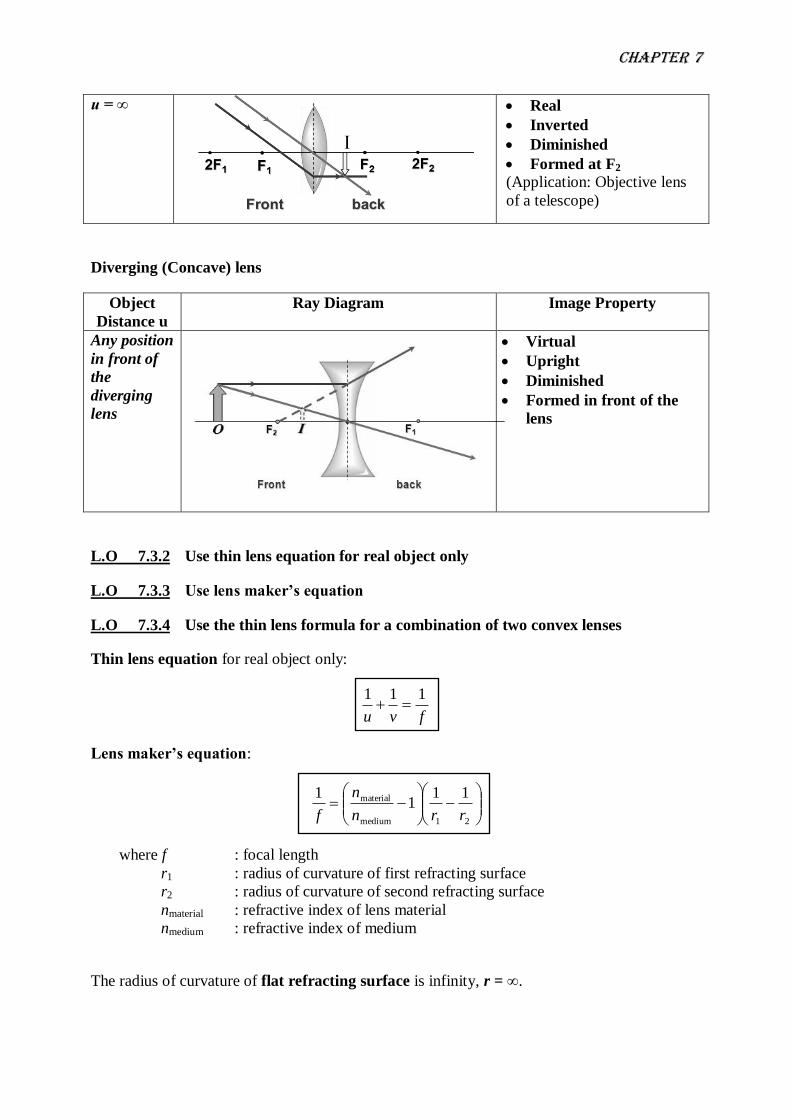
u = ∞
Real
Inverted
Diminished
Formed at F2
(Application: Objective lens
of a telescope)
Diverging (Concave) lens
Object
Distance u
Ray Diagram Image Property
Any position
in front of
the
diverging
lens
Virtual
Upright
Diminished
Formed in front of the
lens
L.O 7.3.2 Use thin lens equation for real object only
L.O 7.3.3 Use lens maker’s equation
L.O 7.3.4 Use the thin lens formula for a combination of two convex lenses
Thin lens equation for real object only:
fvu
111
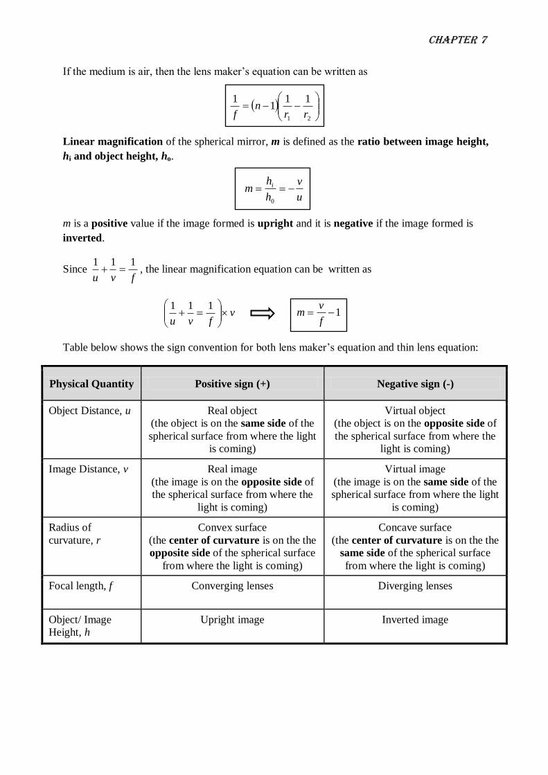
Lens maker’s equation:
21medium
material 111
1
rrn
n
f
where f : focal length
r1 : radius of curvature of first refracting surface
r2 : radius of curvature of second refracting surface
nmaterial : refractive index of lens material
nmedium : refractive index of medium
The radius of curvature of flat refracting surface is infinity, r = ∞.
Chapter 7
If the medium is air, then the lens maker’s equation can be written as
21
111
1
rrn
f
Linear magnification of the spherical mirror, m is defined as the ratio between image height,
hi and object height, ho.
u
v
h
hm i
0
m is a positive value if the image formed is upright and it is negative if the image formed is
inverted.
Since fvu
111 , the linear magnification equation can be written as
vfvu
111 1
f
vm
Table below shows the sign convention for both lens maker’s equation and thin lens equation:
Physical Quantity Positive sign (+) Negative sign (-)
Object Distance, u Real object
(the object is on the same side of the
spherical surface from where the light
is coming)
Virtual object
(the object is on the opposite side of
the spherical surface from where the
light is coming)
Image Distance, v Real image
(the image is on the opposite side of
the spherical surface from where the
light is coming)
Virtual image
(the image is on the same side of the
spherical surface from where the light
is coming)
Radius of
curvature, r
Convex surface
(the center of curvature is on the the
opposite side of the spherical surface
from where the light is coming)
Concave surface
(the center of curvature is on the the
same side of the spherical surface
from where the light is coming)
Focal length, f Converging lenses Diverging lenses
Object/ Image
Height, h
Upright image Inverted image

Chapter 7
Combination of Two Convex Lenses
Many optical instruments, such as microscopes and telescopes, use two converging
lenses together to produce an image.
In both instruments, the 1st lens (closest to the object)is called the objective and the 2
nd
lens (closest to the eye) is referred to as the eyepiece or ocular.
The image formed by the 1st lens is treated as the object for the 2
nd lens and the final
image is the image formed by the 2nd
lens.
The position of the final image in a two lenses system can be determined by applying the
thin lens formula to each lens separately.
The overall magnification of a two lenses system is the product of the magnifications of
the separate lenses.
21mmm
where
m1 : magnification due to the first lens
m2 : magnification due to the second lens

Chapter 7
Example
Question Solution
A biconvex lens is made of glass with
refractive index 1.52 having the radii of
curvature of 20 cm respectively. Calculate the
focal length of the lens in
a. water,
b. carbon disulfide.
(Given nw = 1.33 and nc = 1.63)
A person of height 1.75 m is standing 2.50 m
in from of a camera. The camera uses a thin
biconvex lens of radii of curvature 7.69 mm.
The lens made from the crown glass of
refractive index 1.52.
a. Calculate the focal length of the lens.
b. Sketch a labeled ray diagram to show the
formation of the image.
c. Determine the position of the image and
its height.
d. State the characteristics of the image.
An object is placed 90.0 cm from a glass lens
(n = 1.56) with one concave surface of radius
22.0 cm and one convex surface of radius
18.5 cm. Determine
a. the image position.
b. the linear magnification.
Chapter 7
Question Solution
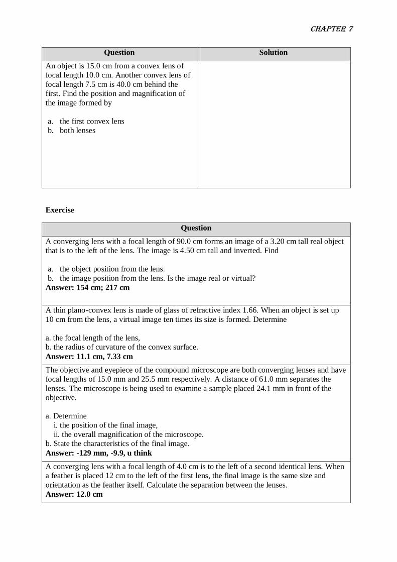
An object is 15.0 cm from a convex lens of
focal length 10.0 cm. Another convex lens of
focal length 7.5 cm is 40.0 cm behind the
first. Find the position and magnification of
the image formed by
a. the first convex lens
b. both lenses
Exercise
Question
A converging lens with a focal length of 90.0 cm forms an image of a 3.20 cm tall real object
that is to the left of the lens. The image is 4.50 cm tall and inverted. Find
a. the object position from the lens.
b. the image position from the lens. Is the image real or virtual?
Answer: 154 cm; 217 cm
A thin plano-convex lens is made of glass of refractive index 1.66. When an object is set up
10 cm from the lens, a virtual image ten times its size is formed. Determine
a. the focal length of the lens,
b. the radius of curvature of the convex surface.
Answer: 11.1 cm, 7.33 cm
The objective and eyepiece of the compound microscope are both converging lenses and have
focal lengths of 15.0 mm and 25.5 mm respectively. A distance of 61.0 mm separates the
lenses. The microscope is being used to examine a sample placed 24.1 mm in front of the
objective.
a. Determine
i. the position of the final image,
ii. the overall magnification of the microscope.
b. State the characteristics of the final image.
Answer: -129 mm, -9.9, u think
A converging lens with a focal length of 4.0 cm is to the left of a second identical lens. When
a feather is placed 12 cm to the left of the first lens, the final image is the same size and
orientation as the feather itself. Calculate the separation between the lenses.
Answer: 12.0 cm


![2 3 4 5 void ordered_fill (float* array, int array_length) { int index; for (index = 0; index < array_length; index++) { array[index] = index; }](https://img.pdfslide.us/doc/110x75/56649e0d5503460f94af6e07/2-3-4-5-void-orderedfill-float-array-int-arraylength-int-index-for.jpg)


![index [] · index ... index](https://img.pdfslide.us/doc/110x75/5e33c50d475fc05b6d5265f9/index-index-index.jpg)
![767 INDEX [] · 767 INDEX ... index](https://img.pdfslide.us/doc/110x75/5e6407d785e377181b6fee19/767-index-767-index-index-.jpg)

![INDEX [] · 2019-04-15 · INDEX ... index](https://img.pdfslide.us/doc/110x75/5e5bc6adf543e8499e5ad9a4/index-2019-04-15-index-index.jpg)