Embed Size (px)
Citation preview

Semester 2
Physics
(SF 026)
Lecture: BP 3
by Yew Sze Ling @ Fiona
Website:
http://yslphysics.weebly.com/

Chapter 1: Electrostatics The study of electric charges at rest, the forces
between them and the electric fields associated with
them.

Overview Electrostatic
Coulomb’s Law Electric Field Electric
Potential
2r
QqF
Electric Field For
Point Charge
q
FE
2r
kQE
Charge in a Uniform
Electric Field
d
VE
oq
WV
Electric
Potential Energy
2r
kQqU
Equipotential
Surface

1.1 Coulomb’s Law
State Coulomb’s law,
Sketch the electric force diagram and
apply Coulomb’s law for a system of point
charges. (2D, maximum four charges)
224 r
kQq
r
QqF
o
Learning Objectives

Coulomb’s Law
Coulomb’s law states that the magnitude of the
electrostatic (Coulomb/electric) force between two point
charges is directly proportional to the product of the
charges and inversely proportional to the square of the
distance between them.
r
QqF
2
Electrostatic Force
Coulomb’s Law
Equation

Coulomb’s Law
Mathematically,
where
F : magnitude of electrostatic (Coulomb’s) force
Q , q : magnitude of charges
r : distance between two point charges
k : electrostatic constant,
k = 9.0 × 10⁹ N m2 C-2
εo : permittivity of free space,
εo = 8.85× 10⁻¹² C2 N-1 m-2
242 r
r
kQqF
o
04
1
k

Coulomb’s Law Graphically,
Notes:
oThe sign of the charge can be ignored when
substituting into the Coulomb’s law equation.
oThe sign of the charges is important in distinguishing
the direction of the electric force.
r
F
0
F
2
1
r0
Gradient, m = kQq

Electric Force Diagram
There are two types of charges in nature – positive and negative charges.
Like charges repel – Repulsive force
Unlike charges attract – Attractive force
The direction of the force is along the straight line joining the two point charges.

Example 1
Sketch the force diagram for q1.
a)
b)
+ − −
+
− +
q1
q1
q2 q3
q2
q3
F21
F31
F21
F31

Example 2
Two point charges, q1 = −20 nC and q2 = 90 nC, are
separated by a distance of 4.0 cm as shown in figure
below.
Find the magnitude and direction of
a. the electric force that q1exerts on q2.
b. the electric force that q2 exerts on q1.
(Given Coulomb’s constant, k = 9.0×10⁹ N m2 C-2)

Example 2 – Solution

Example 2 – Solution

Example 3
Three point charges lie along the x-axis as shown in figure
below.
Calculate the magnitude and direction of the total electric
force exerted on q2.
(Given Coulomb’s constant, k = 9.0×10⁹ N m2 C-2)

Example 3 – Solution

Example 3 – Solution

Example 3 – Solution

Example 4
Figure below shows the three point charges are placed in
the shape of triangular.
Determine the magnitude and direction of the resultant
electric force exerted on q1.
(Given Coulomb’s constant, k = 9.0×10⁹ N m2 C-2)

Example 4 – Solution

Example 4 – Solution

Example 4 – Solution

Example 5
Two point charges, q1 = +4.0µC and q2 = +6.0µC, are
separated by a distance of 50 cm as shown in figure
below.
Determine the position of a point charge q that is placed
on the line joining q1 and q2 such that the net force acting
on it is zero.
(Given Coulomb’s constant, k = 9.0×10⁹ N m2 C-2)

Example 5 – Solution

1.2 Electric Field
Define and use electric field strength,
Use for point charge.
Sketch the electric field strength diagram and determine electric field strength E for a system of charges. (2D, maximum four charges)
q
FE
2r
kQE
Learning Objectives

Electric Field
Electric field is defined as a region of space around isolated charge where an electric force is experienced if a (positive) test charge is placed in the region.
Electric field around charges can be represented by drawing a series of lines. These lines are called electric field lines (lines of force).
The direction of electric field is tangent to the electric field line at each point.
E
+ +

Electric Field Lines
(a) Isolated point charge
Single positive charge Single negative charge
The lines point radially
outward from the charge
The lines point radially
inward from the charge

Electric Field Lines
(b) Two charges
Two equal point charges of opposite sign, +q and -q
The lines are curved and
they are directed from the
positive charge to the
negative charge.

Electric Field Lines
Two equal positive charges, +q and +q
• Neutral point is defined as a
point (region) where the
total electric force is zero.
• It lies along the vertical
dash line.

Electric Field Lines
Two opposite unequal charges, +2q and -q
• note that twice as many lines
leave +2q as there are lines
entering –q
• number of lines is
proportional to magnitude
of charge.

Electric Field Lines
(c) Two opposite charged parallel metal
plate
• The lines go directly from positive
plate to the negative plate.
• The field lines are parallel and equally
spaced in the central region far from
the edges but fringe outward near the
edges. Thus, in the central region, the
electric field has the same magnitude at
all points.
• The fringing of the field near the edges
can be ignored because the separation
of the plates is small compared to their
size.

Electric Field Lines
Characteristic of electric field lines: • The field lines indicate the direction of the electric field (the
field points in the direction tangent to the field line at any point).
• The lines are drawn so that the magnitude of electric field is proportional to the number of lines crossing unit area perpendicular to the lines. The closer the lines, the stronger the field.
• Electric field lines start on positive charges and end on negative charges, and the number starting or ending is proportional to the magnitude of the charge.
• The field lines never cross because the electric field don’t have two value at the same point.
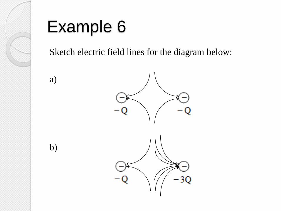
Example 6
Sketch electric field lines for the diagram below:
a)
b)

Electric Field Strength
The electric field strength at a point is defined as the
electric (electrostatic) force per unit (positive) test
charge.
Mathematically
where,
E : magnitude of the electric field strength
F : magnitude of the electric force
q0 : magnitude of test charge
0q
FE

Electric Field Strength
Since,
thus,
It is a vector quantity.
The units of electric field strength is N C-1 or V m-1.
The direction of the electric field strength, E depends on
the sign of isolated charge.
2r
kQqF
q
r
kQq
E2
2r
kQE
In the calculation
of magnitude E,
substitute the
MAGNITUDE
of the charge
only.

What is the difference between
isolated charge and test charge?
0q
FE
2
r
QkE
Test charge
Isolated charge
E
+
+
Isolated charge
Test charge

Since both F and E are vectors, how
to determine the direction of F and E
for a test charge? ?
• The direction of electric
field strength, E depends on
sign of isolated point charge.
• The direction of the electric
force, F depends on the sign
of isolated point charge and
test charge.

A positive isolated point charge
A negative isolated point charge
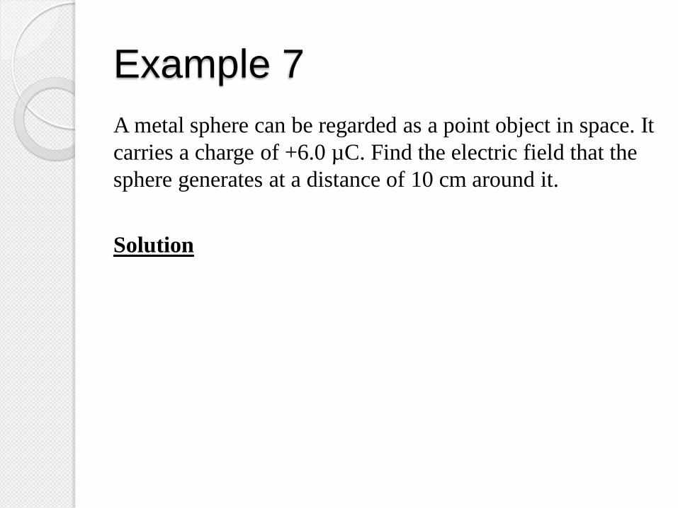
Example 7
A metal sphere can be regarded as a point object in space. It
carries a charge of +6.0 µC. Find the electric field that the
sphere generates at a distance of 10 cm around it.
Solution

Example 8 Two point charges, q1= − 1 C and q2= 4 C, are placed 2 cm
and 3 cm from the point A respectively as shown in figure
below.
Find
a) the magnitude and direction of the electric field
intensity at point A.
b) the total electric force exerted on q0 = − 4 C if it is
placed at point A.
(Given Coulomb’s constant, k = 9.0×10⁹ N m2 C-2)

Example 8 – Solution

Example 8 – Solution

Example 8 – Solution

Example 8 – Solution

Example 9
Two point charges, q1 = − 12 nC and q2 = 12 nC, are placed
0.10 m apart. Calculate the total electric field at point a
and point b.

Example 9 – Solution

Example 9 – Solution

Example 9 – Solution

Example 9 – Solution

Example 9 – Solution

1.3 Electric Potential
Define electric potential,
Define and sketch equipotential lines and
surfaces of an isolated charge and a uniform
electric field
Use for a point charge and a
system of charges.
oq
WV
r
kQV
Learning Objectives

1.3 Electric Potential
Calculate potential difference between two
points
Deduce the change in potential energy
between two points in electric field
Calculate potential energy of a system of
point charges
o
initialfinalq
WVVV
VqU
23
32
13
31
12
21
r
r
r
qqkU
Learning Objectives

Electric Potential
Electric potential, V of a point in the electric field is
defined as the work done in bringing (positive) test charge
from infinity to that point in the electric field per unit test
charge.
oq
WV W∞ : Work done
qo : Test charge

Electric Potential
OR
Electric potential, V of a point in an electric field is defined as the potential energy per unit positive charge at that point in the electric field.
• It is a scalar quantity.
• The unit of electric potential is Volt (V) OR J C 1.
• The electric potential at infinity is considered zero. (V∞ = 0)
oq
UV U : Potential energy
qo : Test charge

Extra Note
+
r
A • Q
+qo
FE Fext
r = ∞
2 where
r
kQqF
drFdW
drFdW
drFdW
oE
rx
x
E
rx
x
E
ext
r
kQqW
rkQqW
drrkQqW
o
r
o
r
o
1
2
r
kQV
rq
kQqV
q
WV
A
o
oA
o
rA
The electric potential at
point A at distance r from
a positive point charge Q

Electric Potential
Since
thus the equation of electric potential can also be written as
r
kQqW o
r
kQV

Electric Potential
The electric potential energy of a positively charged
particle increases when it moves to a point of higher
potential.
The electric potential energy of a negatively charged
particle increases when it moves to a point of lower
potential.
If the value of work done is negative – work done by
the electric force (system).
If the value of work done is positive –work done by
the external force or on the system.
In the calculation of U, W and V, the sign of the charge
MUST be substituted in the related equations.
U=qoV

Equipotential Surface
Equipotential surface (line)is defined as the locus of
points that have the same electric potential.
A point charge A uniform electric field

Equipotential Surface
• The dashed lines represent the equipotential surface
(line).
• The equipotential surfaces (lines) always perpendicular to
the electric field lines passing through them and points in
the direction of decreasing potential.
VA = VB ≠ VC
• From the figures, then the work done to bring a test
charge from B to A is given by
0
BAo
ABoBA
VVq
VqW No work is done in
moving a charge along
the same equipotential
surface.

Example 10
Figure below shows a point A at distance 10 m from the
positive point charge, q = 5C.
Calculate the electric potential at point A and describe the
meaning of the answer.
(Given Coulomb’s constant, k = 9.0×10⁹ N m2 C-2)

Example 10 – Solution

Example 11
Two point charges, q1 = +0.3 C and q2 = −0.4 C are
separated by a distance of 6 m as shown in figure below.
Calculate the electric potential at point A if point A is at
the midpoint of q1 and q2.
(Given Coulomb’s constant, k = 9.0×10⁹ N m2 C-2)

Example 11 – Solution

Example 12
Two point charges, q1 = +12 nC and q2 = −12 nC are
separated by a distance of 8 cm as shown in figure below.
Determine the electric potential at point P.
(Given Coulomb’s constant, k = 9.0×10⁹ N m2 C-2)

Example 12 – Solution

Potential Difference
0q
WVVV initialfinal OR
o
BABAAB
q
WVVV

Potential Difference The work done to bring a charge from one point to
another in the field does not depend on the path taken
(because the work done by conservative force).

Example 13
Two points, S and T are located around a point charge of
+5.4 nC as shown in figure below.
Calculate
a) the electric potential difference between points S and T.
b) the work done in bringing a charge of 1.5 nC from
point T to point S.
(Given Coulomb’s constant, k = 9.0×10⁹ N m2 C-2)

Example 13 – Solution

Example 13 – Solution

Changes in Potential Energy
From the definition of electric potential difference, V
Therefore the change in a potential energy is given by
0
Δq
WV UW and
0
Δq
UV
VqU Δ0
Ufinal ‒ Uinitial Vfinal ‒ Vinitial

Potential Energy of A System
The total electric potential energy of the system of
charges is the total work done to bring all the charges from
infinity to their final positions.
The total potential energy, U can be expressed as
23
32
13
31
12
21
r
r
r
qqkU

Extra Note
In the system of charges, suppose there were originally no
charges at the points A, B and C as in the figure above.
Step 1:
The charge q1 is brought from infinity and placed at
point A. Since originally there were no charges, the
charge q1 does not experience any electric force when it is
brought from infinity, that is F = 0. Hence VA = 0.
Since U1 = q1VA, hence
1 0U
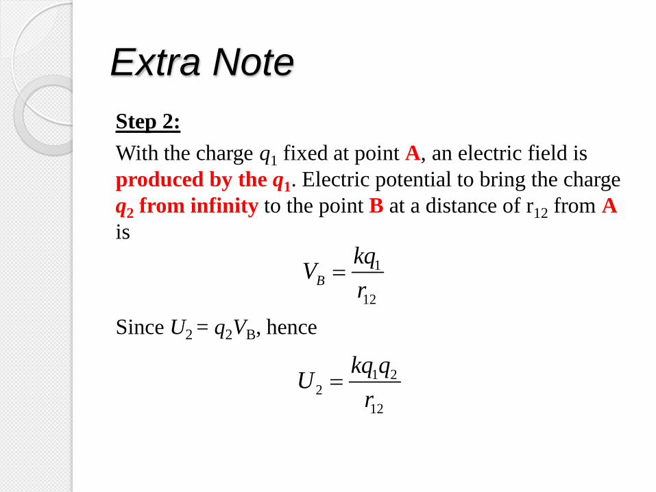
Extra Note
Step 2:
With the charge q1 fixed at point A, an electric field is
produced by the q1. Electric potential to bring the charge
q2 from infinity to the point B at a distance of r12 from A
is
Since U2 = q2VB, hence
1
12
B
kqV
r
1 22
12
kq qU
r

Extra Note
With the charge q1 fixed at point A and q2 at the point B,
the electric potential at the point C is
Since U3 = q3VC, hence
1 2
13 23
C
kq kqV
r r
1 3 2 33
13 23
kq q kq qU
r r

Extra Note
Therefore, the electric potential energy of the system,
321 UUUU
23
2
13
13
12
210r
q
r
qkq
r
qkq
23
32
13
31
12
21
r
qkq
r
qkq
r
qkq
23
32
13
31
12
21
r
r
r
qqkU

Example 14 Two point charges, Q1= +2.0 C and Q2= 6.0 C, are
placed 4.0 cm and 5.0c m from a point P respectively as
shown in figure below.
a. Calculate the electric potential at P due to the charges.
b. If a charge Q3= +3.0 C moves from infinity to P,
determine the change in electric potential energy for
this charge.
c. When the charge Q3 at point P, calculate the electric
potential energy for the system of charges.
(Given Coulomb’s constant, k = 9.0×10⁹ N m2 C-2)

Example 14 – Solution

Example 14 – Solution

Example 14 – Solution

1.4 Charge In A Uniform Electric
Field Explain quantitatively with the aid of a
diagram the motion of charge in a uniform
electric field.
Use for uniform electric field.
Cases:
• Stationary charge
• Charge moving perpendicularly to the field
• Charge moving parallel to the field
• Charge in dynamic equilibrium
d
VE
Learning Objectives

Uniform Electric Field
A uniform electric field is represented by a set of
electric field lines which are straight, parallel to each
other and equally spaced
It can be produced by two flat parallel metal plates which
is charged, one with positive and one is negative and is
separated by a distance.
Direction of E: (+) ve plat to (–) plat

Case 1 : Stationary Charge
Positive stationary charge Negative stationary charge
Force experienced by charge is in the
same direction as electric field, E. Force experienced by charge is in the
opposite direction as electric field,
E.

Case 1 : Stationary Charge
Consider a stationary particle of charge qo and mass m
is placed in a uniform electric field E, the electric
force Fe exerted on the charge is given by
Since only electric force exerted on the particle, thus
this force contributes the nett force, F and causes the
particle to accelerate.
According to Newton’s second law, then the magnitude
of the acceleration of the particle is
EqF oe
maEq
maFF
o
e
m
Eqa e

Case 1 : Stationary Charge
Because the electric field is uniform (constant in
magnitude and direction) then the acceleration of the
particle is constant.
If the particle has a positive charge, its acceleration is
in the direction of the electric field. If the particle has a
negative charge (electron), its acceleration is in the
direction opposite the electric field.
Case 2 : Charge moving
perpendicularly to the field
Positive charge Negative charge
• The positive charge will be
deflected and moves along a
parabolic path towards the
negative plate.
• The positive charge moves under
the influence of the electric force
which is at the same direction as
electric field lines.
• The negative charge will be
deflected and moves along a
parabolic path towards the
positive plate.
• The negative charge moves under
the influence of the electric force
which is opposite direction to the
electric field lines.

Case 2 : Charge moving
perpendicularly to the field Consider an electron (e) with mass, me enters a uniform
electric field, E perpendicularly with an initial velocity
u, the upward electric force will cause the electron to
move along a parabolic path towards the upper plate.
The electric force Fe exerted on the charge,
EqF oe

Case 2 : Charge moving
perpendicularly to the field From Newton’s second law,
Therefore the magnitude of the electron’s acceleration is
given by
maF
upward) :(direction e
ym
eEa 0xa;
maEq
maFF
o
e

x -
component
y - component
u
v
s
a
uvx
0u
yyyy
yyy
sauv
tauv
2
22
tus xx
tvus
tatus
yyy
yyy
2
1
2
1 2
0
e
ym
eEa
The path makes by the electron is similar to the motion of a ball projected horizontally above the ground
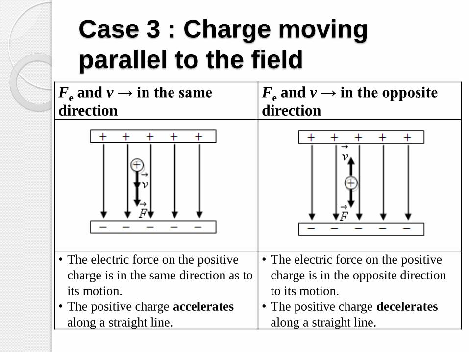
Case 3 : Charge moving
parallel to the field Fe and v → in the same
direction Fe and v → in the opposite
direction
• The electric force on the positive
charge is in the same direction as to
its motion.
• The positive charge accelerates
along a straight line.
• The electric force on the positive
charge is in the opposite direction
to its motion.
• The positive charge decelerates
along a straight line.
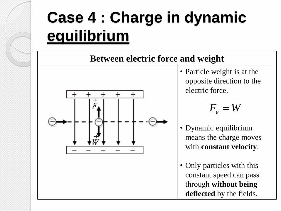
Case 4 : Charge in dynamic
equilibrium
Between electric force and weight
• Particle weight is at the
opposite direction to the
electric force.
• Dynamic equilibrium
means the charge moves
with constant velocity.
• Only particles with this
constant speed can pass
through without being
deflected by the fields.
WFe

Uniform Electric Field
The graph is a straight line with
negative constant gradient, thus
d
VE
d
V
r
VE
0
0

Example 15
Two parallel plates are separated 5.0 mm apart. The
electric field strength between the plates is 1.0 104 N
C1. A small charge of +4.0 nC is moved from one
conducting plate to another. Calculate
a. the potential difference between the plates
b. the work done on the charge.

Example 15 – Solution

Example 16
If the plates are horizontal and separated by 1.0 cm,
the plates are connected to 100 V battery, the
magnitude of the electric field is 1.0×10⁴ N C-1. If an
electron is released from the rest at the upper plate,
determine
a. the acceleration of the electron.
b. the speed and the kinetic energy required to travel
to the lower plate.
c. the time required to travel to the lower plate.
[mass of electron = 9.11×10⁻³¹ kg;
charge of electron = 1.60×10⁻¹⁹ C ]

Example 16 – Solution

Example 16 – Solution

Example 16 – Solution

Example 17 The figure shows a section of the deflection system of a cathode ray
oscilloscope. An electron travelling at a speed of 1.5×10⁷ m s-1 enters
the space between two parallel metal plates 60 mm long. The electric
field between the plates is 4.0×10³ V m-1.
a. Copy the figure, sketch the path of the electron in between plates,
and after emerging from the space between the plates.
b. Find the acceleration of the electron between the plates.
c. Determine the velocity when it emerges from the space between
the plates.

Example 17 – Solution

Example 17 – Solution

Summary
Electrostatic
Coulomb’s Law Electric Field Electric
Potential
2r
QqF
Electric Field For
Point Charge
q
FE
2r
kQE
Charge in a Uniform
Electric Field
d
VE
oq
WV
Electric
Potential Energy
2r
kQqU
Equipotential
Surface