Embed Size (px)
Citation preview
FINAL DRIVE
7.1
CHAPTER 7
FINAL DRIVE
7
SPECIAL TOOLS . . . . . . . . . . . . . . . . . . . . . . . . . . . . . . . . . . . . . . . . . . . . . . . . . . . . . . . 7.2TORQUE SPECIFICATIONS. . . . . . . . . . . . . . . . . . . . . . . . . . . . . . . . . . . . . . . . . . . . . . . 7.2FRONT BEARING CARRIER . . . . . . . . . . . . . . . . . . . . . . . . . . . . . . . . . . . . . . . . . . . . . . 7.2
BEARING CARRIER INSPECTION / REMOVAL. . . . . . . . . . . . . . . . . . . . . . . . . . . . . . . 7.2BEARING REPLACEMENT . . . . . . . . . . . . . . . . . . . . . . . . . . . . . . . . . . . . . . . . . . . . . . . 7.3BEARING CARRIER INSTALLATION . . . . . . . . . . . . . . . . . . . . . . . . . . . . . . . . . . . . . . . 7.4
FRONT DRIVE SHAFT . . . . . . . . . . . . . . . . . . . . . . . . . . . . . . . . . . . . . . . . . . . . . . . . . . . 7.6FRONT PROPSHAFT . . . . . . . . . . . . . . . . . . . . . . . . . . . . . . . . . . . . . . . . . . . . . . . . . . . . 7.7
REMOVAL / INSTALLATION (XP / HD) . . . . . . . . . . . . . . . . . . . . . . . . . . . . . . . . . . . . . . 7.7REMOVAL / INSTALLATION (6X6) . . . . . . . . . . . . . . . . . . . . . . . . . . . . . . . . . . . . . . . . . 7.7REMOVAL / INSTALLATION (CREW) . . . . . . . . . . . . . . . . . . . . . . . . . . . . . . . . . . . . . . . 7.8SUPPORT BEARING REPLACEMENT (CREW). . . . . . . . . . . . . . . . . . . . . . . . . . . . . . . 7.9
PROPSHAFT U-JOINT SERVICE. . . . . . . . . . . . . . . . . . . . . . . . . . . . . . . . . . . . . . . . . . 7.10FRONT GEARCASE - CENTRALIZED HILLIARD . . . . . . . . . . . . . . . . . . . . . . . . . . . . . 7.12
ALL WHEEL DRIVE OPERATION . . . . . . . . . . . . . . . . . . . . . . . . . . . . . . . . . . . . . . . . . 7.13AWD DIAGNOSIS. . . . . . . . . . . . . . . . . . . . . . . . . . . . . . . . . . . . . . . . . . . . . . . . . . . . . . 7.14GEARCASE REMOVAL / DISASSEMBLY / INSPECTION . . . . . . . . . . . . . . . . . . . . . . 7.15ASSEMBLY / INSPECTION . . . . . . . . . . . . . . . . . . . . . . . . . . . . . . . . . . . . . . . . . . . . . . 7.18SETTING RING GEAR BACKLASH. . . . . . . . . . . . . . . . . . . . . . . . . . . . . . . . . . . . . . . . 7.20GEARCASE INSTALLATION . . . . . . . . . . . . . . . . . . . . . . . . . . . . . . . . . . . . . . . . . . . . . 7.21
MID / REAR BEARING CARRIER. . . . . . . . . . . . . . . . . . . . . . . . . . . . . . . . . . . . . . . . . . 7.22INSPECTION / REMOVAL . . . . . . . . . . . . . . . . . . . . . . . . . . . . . . . . . . . . . . . . . . . . . . . 7.22DISASSEMBLY / ASSEMBLY . . . . . . . . . . . . . . . . . . . . . . . . . . . . . . . . . . . . . . . . . . . . 7.23INSTALLATION . . . . . . . . . . . . . . . . . . . . . . . . . . . . . . . . . . . . . . . . . . . . . . . . . . . . . . . 7.24
MID / REAR DRIVE SHAFT. . . . . . . . . . . . . . . . . . . . . . . . . . . . . . . . . . . . . . . . . . . . . . . 7.25MID PROPSHAFT (6X6) . . . . . . . . . . . . . . . . . . . . . . . . . . . . . . . . . . . . . . . . . . . . . . . . . 7.26MID GEARCASE (6X6) . . . . . . . . . . . . . . . . . . . . . . . . . . . . . . . . . . . . . . . . . . . . . . . . . . 7.27
GEARCASE REMOVAL . . . . . . . . . . . . . . . . . . . . . . . . . . . . . . . . . . . . . . . . . . . . . . . . . 7.27GEARCASE DISASSEMBLY . . . . . . . . . . . . . . . . . . . . . . . . . . . . . . . . . . . . . . . . . . . . . 7.29GEARCASE ASSEMBLY . . . . . . . . . . . . . . . . . . . . . . . . . . . . . . . . . . . . . . . . . . . . . . . . 7.31GEARCASE INSTALLATION . . . . . . . . . . . . . . . . . . . . . . . . . . . . . . . . . . . . . . . . . . . . . 7.34MID GEARCASE EXPLODED VIEW . . . . . . . . . . . . . . . . . . . . . . . . . . . . . . . . . . . . . . . 7.35
DRIVE SHAFT SERVICE . . . . . . . . . . . . . . . . . . . . . . . . . . . . . . . . . . . . . . . . . . . . . . . . 7.36DRIVE SHAFT / CV JOINT HANDLING TIPS . . . . . . . . . . . . . . . . . . . . . . . . . . . . . . . . 7.36OUTER CV JOINT / BOOT REPLACEMENT. . . . . . . . . . . . . . . . . . . . . . . . . . . . . . . . . 7.36INNER PLUNGING JOINT / BOOT REPLACEMENT . . . . . . . . . . . . . . . . . . . . . . . . . . 7.38DRIVE SHAFT EXPLODED VIEW . . . . . . . . . . . . . . . . . . . . . . . . . . . . . . . . . . . . . . . . . 7.40
REAR PROPSHAFT (6X6) . . . . . . . . . . . . . . . . . . . . . . . . . . . . . . . . . . . . . . . . . . . . . . . 7.41REAR GEARCASE (6X6) . . . . . . . . . . . . . . . . . . . . . . . . . . . . . . . . . . . . . . . . . . . . . . . . 7.42
GENERAL OPERATION. . . . . . . . . . . . . . . . . . . . . . . . . . . . . . . . . . . . . . . . . . . . . . . . . 7.42GEARCASE REMOVAL . . . . . . . . . . . . . . . . . . . . . . . . . . . . . . . . . . . . . . . . . . . . . . . . . 7.43GEARCASE DISASSEMBLY . . . . . . . . . . . . . . . . . . . . . . . . . . . . . . . . . . . . . . . . . . . . . 7.44REAR GEARCASE ASSEMBLY. . . . . . . . . . . . . . . . . . . . . . . . . . . . . . . . . . . . . . . . . . . 7.46REAR GEARCASE INSTALLATION . . . . . . . . . . . . . . . . . . . . . . . . . . . . . . . . . . . . . . . 7.49REAR GEARCASE EXPLODED VIEW . . . . . . . . . . . . . . . . . . . . . . . . . . . . . . . . . . . . . 7.50
9923499 - 2011 / 2012 RANGER 800 Service Manual© Copyright 2011 Polaris Sales Inc.

FINAL DRIVE
SPECIAL TOOLS
SPX Corp: 1-800-328-6657 or http://polaris.spx.com/
TORQUE SPECIFICATIONS
Wheel and Hub Torque Table
FRONT BEARING CARRIER
Bearing Carrier Inspection / Removal
1. Elevate front of vehicle and safely support machine under the frame area.
2. Check bearings for side play by grasping the top and bottom of the tire firmly and checking for movement. The tire should rotate smoothly without binding or rough spots.
3. Remove the (4) wheel nuts and remove front wheel.
4. Remove the cotter pin and loosen the front wheel hub castle nut. Remove the nut, and (2) cone washers from the front wheel hub assembly.
5. Remove the two brake caliper mounting bolts.CAUTION: Do not hang caliper by the brake line. Use wire to hang caliper to prevent damage to brake line.
PART NUMBER TOOL DESCRIPTION
2872608 Roll Pin Removal Tool
PU-48951 Axle Boot Clamp Tool
ITEM NUT TYPE SPECIFICATION
Aluminum Wheels (Cast)
Lug Nut#1
30 ft. lbs. + 90° (1/4 turn)
Steel Wheels (Black / Camo)
Flange Nut#2
35 ft. lbs. (47 Nm)
Front HubCastle Nut
- 80 ft. lbs. (108 Nm)
Mid / Rear Hub Castle Nut
- 110 ft. lbs. (150 Nm)
CAUTION
Serious injury may result if machine tips or falls. Be sure machine is secure before beginning this service procedure. Wear eye protection when
removing bearings and seals.
#1 #2
Aluminum Wheel(LE Models)
30 ft. lbs. + 90° (1/4 turn)
Steel Wheel(Standard Models)35 ft. lbs. (47 Nm)
Castle Nut
Cotter Pin
ConeWashers
7.29923499 - 2011 / 2012 RANGER 800 Service Manual
© Copyright 2011 Polaris Sales Inc.

FINAL DRIVE
7
6. Remove the front wheel hub assembly.
7. Remove the steering tie rod end fastener from the front bearing carrier.
8. Remove lower shock mounting fastener attached to the upper A-arm and remove shock from the A-arm.
9. Remove the upper and lower ball joint pinch bolts.
10. Using a soft faced hammer, lightly tap on the bearing carrier while removing upper and lower ball joint ends.
11. Remove the bearing carrier from the front drive shaft.
12. Rotate bearing by hand and check for smooth rotation. Visually inspect bearings for moisture, dirt, or corrosion.
NOTE: Due to extremely close tolerances and minimal wear, the bearing must be inspected visually, and by feel. While rotating bearings by hand, inspect for rough spots, discoloration, or corrosion. The bearings should turn smoothly and quietly, with no detectable up and down movement and minimal movement sideways between inner and outer race.
13. Replace bearing if moisture or corrosion is evident.
Bearing Replacement
Bearing Removal
1. Remove outer snap ring.
2. From back side of the bearing carrier, tap on the outer bearing race with a drift punch in the reliefs as shown.
3. Drive bearing out evenly by tapping on outer race only. Once bearing is at bottom of casting, support casting on outer edges so bearing can be removed.
SteeringTie Rod End
PinchBolts
SnapRing
7.39923499 - 2011 / 2012 RANGER 800 Service Manual
© Copyright 2011 Polaris Sales Inc.

FINAL DRIVE
4. Inspect bearing carrier housing for scratches, wear or damage. Replace front bearing carrier if damaged.
Bearing Installation
5. Thoroughly clean the front bearing carrier housing and the outer race on the new bearing. Be sure that all oil residue has been removed from each surface.
6. Support the bottom of the bearing carrier housing.
7. Apply Loctite® 603™ retaining compound to the outer circumference of the new bearing race and carefully press the new bearing into the bearing carrier housing.
NOTE: Use care to not allow any of the Loctite®
compound to get in the bearing.
8. Wipe the housing clean of any excess compound and install the snap ring.
Bearing Carrier Installation
1. Install the end of the drive shaft through the backside of the bearing carrier.
2. Install the upper and lower ball joint ends into the front bearing carrier.
3. Install pinch bolts and torque to specification.
4. Install shock to A-arm and torque fastener to specification.
5. Apply grease to the drive shaft splines.
CAUTIONUse an arbor and press only on the outer race,
otherwise bearing damage may occur.
ApplyLoctite® 603™
Bearing
Snap Ring
= T
Pinch Bolts:23 ft. lbs. (31 Nm)
= T
Shock Mounting Bolts:30 ft. lbs. (41 Nm)
23 ft. lbs.(31 Nm)
30 ft. lbs.(41 Nm)
7.49923499 - 2011 / 2012 RANGER 800 Service Manual
© Copyright 2011 Polaris Sales Inc.

FINAL DRIVE
7
6. Install front wheel hub assembly, cone washers, and hand tighten the castle nut. Install washers with domed side out.
7. Install the steering tie rod end onto the front bearing carrier and torque fastener to 40 ft. lbs. (54 Nm).
8. Install the front brake caliper. Install the mounting bolts and torque to 30 ft. lbs. (41 Nm).
9. Torque wheel hub nut to 80 ft. lbs. (108 Nm) and install a NEW cotter pin. Tighten nut slightly if necessary to align cotter pin holes.
10. Install wheel and (4) wheel nuts. Torque wheel nuts to specification.
11. Rotate wheel and check for smooth operation. Bend both ends of cotter pin around the end of the shaft.
= T
Tie Rod End Fastener:40 ft. lbs. (54 Nm)
Out
Cone Washers
WheelHub
40 ft. lbs.54 (Nm)
30 ft. lbs.(41 Nm)
= T
Front Caliper Mounting Bolts:30 ft. lbs. (41 Nm)
CAUTION
New bolts have a pre-applied locking agent which is destroyed upon removal. Always use
new brake caliper mounting bolts upon assembly.
= T
Front Hub Castle Nut:80 ft. lbs. (108 Nm)
= T
Wheel Nuts:Steel Wheels: 35 ft. lbs. (47 Nm)
Aluminum Wheels: 30 ft. lbs. + 90° (1/4 turn)
80 ft. lbs.(108 Nm)
NEW Cotter Pin
7.59923499 - 2011 / 2012 RANGER 800 Service Manual
© Copyright 2011 Polaris Sales Inc.

FINAL DRIVE
FRONT DRIVE SHAFT
Removal
1. Perform the “Bearing Carrier Inspection / Removal” procedure listed under the “FRONT BEARING CARRIER” section within this chapter.
NOTE: Perform all removal steps with the exception of removing the steering tie rod end. It will not be necessary to remove the tie rod end from the front bearing carrier when removing the front drive shaft.
2. Remove the drive shaft from the front bearing carrier.
3. With a short, sharp jerk, remove drive shaft from the front gearcase.
4. Refer to the “DRIVE SHAFT SERVICE” procedure if repairing the drive shaft.
Installation
1. Install new spring ring on the end of the drive shaft. Apply an anti-seize compound to splines.
2. Align splines of drive shaft with front gearcase and reinstall the drive shaft. Use a rubber mallet to tap on the outboard end of the drive shaft if necessary.
3. Install drive shaft into the front bearing carrier.
4. Perform the “Bearing Carrier Installation” procedure listed under the “FRONT BEARING CARRIER” section within this chapter.
CAUTION
Serious injury may result if machine tips or falls. Be sure machine is secure before beginning
this service procedure.
7.69923499 - 2011 / 2012 RANGER 800 Service Manual
© Copyright 2011 Polaris Sales Inc.

FINAL DRIVE
7
FRONT PROPSHAFT
Removal / Installation (XP / HD)
1. Elevate and safely support vehicle under the frame. The use of a vehicle hoist is recommended for this procedure.
2. Access the front propshaft roll pin through the skid plate hole.
3. Use the Roll Pin Removal Tool (PN 2872608), to drive out the roll pin from the propshaft.
4. Remove the (8) T27 Torx-head screws retaining the floor cover and remove the cover from the vehicle.
5. Slide the propshaft back and away from front gearcase, then pull the shaft sharply forward to remove it from the transmission shaft.
6. Using care, pull the propshaft towards the left side of the frame and slide it out the left rear side of the vehicle in front of the PVT system.
7. Reverse this procedure to reinstall the front propshaft.
8. Use a NEW roll pin upon installation.
Removal / Installation (6x6)
1. Elevate and safely support vehicle under the frame. The use of a vehicle hoist is recommended for this procedure.
2. Access the front propshaft roll pin through the skid plate hole.
3. Use the Roll Pin Removal Tool (PN 2872608), to drive out the roll pin from prop shaft.
4. Remove the (8) T27 Torx-head screws retaining the floor cover and remove the cover from the vehicle.
5. Slide the propshaft back and away from front gearcase, then pull the shaft sharply forward to remove it from the transmission shaft.
6. Using care, pull the propshaft towards the right side of the frame and slide it out the right rear portion of the frame.
NOTE: Avoid making contact with the shift cable and cable mounting tab during removal to prevent component damage.
7. Reverse this procedure to install the front propshaft.
8. Use a NEW roll pin upon installation.
CAUTION
Serious injury may result if machine tips or falls. Be sure machine is secure before beginning this service procedure. Wear eye protection when
removing bearings and seals.
Roll Pin Removal Tool (PN 2872608)
CAUTION
Serious injury may result if machine tips or falls. Be sure machine is secure before beginning this service procedure. Wear eye protection when
removing bearings and seals.
Roll Pin Removal Tool (PN 2872608)
See NOTE
7.79923499 - 2011 / 2012 RANGER 800 Service Manual
© Copyright 2011 Polaris Sales Inc.

FINAL DRIVE
Removal / Installation (CREW)
1. Elevate and safely support vehicle under the frame. The use of a vehicle hoist is recommended for this procedure.
NOTE: Propshaft roll pin removal is only required if removing the front portion of the propshaft.
2. Access front propshaft roll pin through skid plate hole.
3. Use the Roll Pin Removal Tool (PN 2872608), to drive out the roll pin from prop shaft.
4. Remove the front seat base and large storage container to access the support bearing.
5. Remove (2) nuts and bolts retaining bearing support.
6. Slide the rear portion of the shaft back on the transmission shaft and move both shafts toward the left side of the vehicle to separate them.
7. If removing the front portion of the propshaft, slide it back and away from front gearcase to remove it.
8. If removing the rear portion, remove the bearing support (upper & lower half).
9. Using care, pull the rear portion of the propshaft towards the left side of the frame and slide it out the left rear side of the vehicle in front of the PVT system.
10. Reverse this procedure to reinstall and assemble the front propshaft.
11. Torque bearing support fasteners to specification.
12. If front propshaft was removed, use a NEW roll pin upon installation.
CAUTION
Serious injury may result if machine tips or falls. Be sure machine is secure before beginning this service procedure. Wear eye protection when
removing bearings and seals.
Roll Pin Removal Tool (PN 2872608)
Support Bearing
= T
Bearing Support Fasteners:30-36 ft. lbs. (41-49 Nm)
7.89923499 - 2011 / 2012 RANGER 800 Service Manual
© Copyright 2011 Polaris Sales Inc.

FINAL DRIVE
7
Support Bearing Replacement (CREW)
1. Follow steps 4-6 of the “Removal / Installation (CREW)” procedure.
2. Remove the bearing support (upper and lower half) and the retaining ring. Loosen the (2) set screws retaining the bearing to the shaft.
3. Slide the bearing off the end of the shaft.
NOTE: If bearing is seized on the shaft, remove the rear portion of the shaft from the vehicle. Refer to “Removal / Installation (CREW)”.
4. Clean surface of the shaft and install the new bearing.
5. Install a new retaining ring and slide the bearing tight against the retaining ring.
6. Apply Loctite® 242™ to the set screw threads and torque the (2) bearing set screws to specification.
7. Align the front and rear portions of the propshaft as shown below and slide them together.
8. Install the upper and lower halves of the bearing support along with the (2) fasteners. Torque the support bearing fasteners to specification.
9. Grease the propshaft yoke(s).
10. Reinstall the large storage container and front seat base.
= T
Bearing Set Screws:30-35 in. lbs. (3.4-4.0 Nm)
Loosen
Remove
30-35 in. lbs.(3.4-4.0 Nm)
RetainingRing
= T
Bearing Support Fasteners:30-36 ft. lbs. (41-49 Nm)
7.99923499 - 2011 / 2012 RANGER 800 Service Manual
© Copyright 2011 Polaris Sales Inc.

FINAL DRIVE
PROPSHAFT U-JOINT SERVICE
Disassembly
1. Remove internal or external snap ring from all bearing caps.
NOTE: If yoke or bearing is removed, cross bearing must be replaced. Note orientation of grease fitting and mark inner and outer yoke for correct re-positioning during installation.
2. Support inner yoke as shown and drive outer yoke down (bearing cap out) with a soft face hammer.
3. Support U-joint in vise as shown and drive inner yoke down to remove remaining bearing caps.
4. Force U-joint cross to one side and lift out of inner yoke.
CAUTION
Always wear eye protection.
7.109923499 - 2011 / 2012 RANGER 800 Service Manual
© Copyright 2011 Polaris Sales Inc.

FINAL DRIVE
7
Assembly
1. Install new bearing caps in yoke by hand. Carefully install U-joint cross with grease fitting properly positioned inward toward center of shaft. Take care not to dislodge needle bearings upon installation of cross joint. Tighten vise to force bearing caps in.
2. Using a suitable arbor, fully seat bearing cap in one side.
3. Continually check for free movement of bearing cross as bearing caps are assembled.
4. Install snap ring to contain bearing cap just installed. Repeat procedure for other side.
5. Install outer yoke, aligning marks made before disassembly.
6. Repeat Steps 1-4 to install bearing caps on outer yoke.
7. Seat all bearing caps against snap rings by supporting cross shaft and tapping on each corner as shown.
8. When installation is complete, yokes must pivot freely in all directions without binding. If the joint is stiff or binding, tap the yoke lightly to center the joint until it pivots freely in all directions.
7.119923499 - 2011 / 2012 RANGER 800 Service Manual
© Copyright 2011 Polaris Sales Inc.

FINAL DRIVE
FRONT GEARCASE - CENTRALIZED HILLIARD
Exploded View
REF# DESCRIPTION QTY REF# DESCRIPTION QTY
1 Screws, 1/4-20 8 20 Fill Plug 1
2 Armature Plate 1 21 Vent Tube 1
3 Bushing 1 22 Nylon Spacer 2
4 Output Cover 1 23 AWD Coil / Coil Pocket Insert 1
5 Gearcase 1 24 Thrust Plate 1
6 Output Hub 2 25 O-Ring 1
7 Plastic Clip 1 26 Grommet 1
8 Roll Cage 1 27 Set Screw 1
9 Spacer, Gear 1 28 Oil Seal 2
10 Clutch Housing / Ring Gear 1 29 Rollers 20
11 Bushing 1 30 H-Clip Springs 20
12 Input Cover 1 31 Oil Seal 1
13 O-Ring 1 32 Drain Plug Asm. w/Magnet 1
14 Retaining Ring 1 33 Dowel Pin 1
15 Ball Bearing 3 34 Needle Roller Bearing 1
16 Pinion Gear 1 35 Retaining Ring 1
17 Dowel Pin 1 36 Spring, Wire Form 2
18 Bearing 1 37 Torsion Spring 1
19 Thrust Button Asm. 1 38 Spring Retainer 1
1
2
3
4
5
6
7
8
9 1011
12
13
14
16
1718
19
2021
22
23
15
24
25
26
8-10 ft. lbs.(11-14 Nm)
7-11 ft. lbs.(10-15 Nm)
6
15
15
27
28
30
29
31
32
33
34
8-10 ft. lbs.(11-14 Nm)
7-11 ft. lbs.(10-15 Nm)
1
22
28
3536
3738
7.129923499 - 2011 / 2012 RANGER 800 Service Manual
© Copyright 2011 Polaris Sales Inc.

FINAL DRIVE
7
All Wheel Drive Operation
The AWD switch may be turned on or off while the vehicle is moving, however, AWD will not enable until the engine RPM drops below 3100. Once the AWD is enabled, it remains enabled until the switch is turned off.
Engage the AWD switch before getting into conditions where the front wheel drive may be needed. If the rear wheels are spinning, release the throttle before switching to AWD.
With the AWD switch off, the vehicle drives through the rear wheels only (2 wheel drive). When the AWD is enabled, the front drive acts as an on-demand AWD system. This means, the front drive will engage once the rear wheels have lost traction, and will remain engaged until the torque requirement goes away (i.e. rear wheels regain traction).
AWD Engagement: When the AWD switch is activated, the AWD coil is powered by a 12 Vdc input which creates a magnetic field. This magnetic field attracts an armature plate that is keyed to the roll cage. When the ring gear and roll cage are spinning (vehicle is moving), the energized coil and armature plate will apply drag to the roll cage that indexes the rollers inside the ring gear to an engagement position. While in the engagement position, the front drive will be in an “over-running” condition (not engaged), until the rear wheels lose traction. Once the rear wheels begin to lose traction, the front drive will engage by coupling the output hubs to the ring gear via the rollers. The front drive will remain engaged until the torque requirement goes away (i.e. rear wheels regain traction).
AWD Disengagement: Once the rear wheels regain traction, the front wheels will return to the “over-running” condition. The vehicle is now back to rear wheel drive until the next loss of rear wheel traction occurs.
Torsion Spring Operation: The torsion spring acts as a return mechanism to help disengage the coupling of the output hubs and ring gear by creating an “over-running” condition for the rollers upon disengagement.
CAUTION
Switching to AWD while the rear wheels are spinning may cause severe drive shaft and
gearcase damage. Always switch to AWD while the rear wheels have traction or are at rest.
CAUTION
If the rear wheels are spinning, release the throttle before turning the AWD switch on.If AWD is engaged while the wheels are
spinning, severe drive shaft and front gearcase damage could result.
Roll Cage& H-Springs
Output Hubs
RingGear
Rollers
RingGear
Centers Roll Cage and
TorsionSpring
Roll Cage& Rollers
Rollers in Ring Gear
OutputHubs
7.139923499 - 2011 / 2012 RANGER 800 Service Manual
© Copyright 2011 Polaris Sales Inc.

FINAL DRIVE
AWD Diagnosis
Symptom: AWD Will Not Engage
1. Check the gearcase coil resistance. To test the coil resistance, measure between Grey and Brown/White wires. Measurement should be within specification.
2. Turn the ignition switch and AWD switch on and place gear selector in High or Low gear. Check for minimum battery voltage at Gray and Brown/White chassis wires that power the coil. A minimum of 11 Vdc should be present.
3. If electrical tests are within specification, remove gearcase (see “Gearcase Removal”) and inspect components.
4. Inspect armature plate for a consistent wear pattern. There should be two distinct wear bands (one band inside the other). If only one band of wear is present (or if there is wear between the two bands), inspect the coil area as indicated in Step 5. A wear band with an interrupted wear mark may indicate a warped plate, which may cause intermittent operation.
5. Check to make sure the coil is seated in the U-shaped insert that is pressed into the gearcase cover. The top of the coil should be seated below the U-shaped insert. The U-shaped insert controls the pole gap. If the top of the coil is above the surface of the U-shaped insert it raises the armature plate, thereby increasing pole gap. If the pole gap increases, the coil will not be strong enough to engage the AWD system. If this is found, replace the cover plate assembly.
6. Inspect the rollers for nicks and scratches. The rollers must slide up, down, in and out freely within the roll cage sliding surfaces and H-springs.
7. Inspect the roll cage assembly for cracks or excessive wear. If damaged, replace the roll cage assembly.
Front Gearcase Coil Resistance: 21.6 - 26.4 Ohms
Armature Plate
Check for Wear Bands
Gearcase Cover Plate Asm.
Coil
U-shaped insert
Side cutaway view ofCentralized Hilliard cover
Rollers
Roll Cage Assembly
7.149923499 - 2011 / 2012 RANGER 800 Service Manual
© Copyright 2011 Polaris Sales Inc.

FINAL DRIVE
7
Gearcase Removal
1. Stop engine, place machine in gear and set parking brake.
2. Elevate front of vehicle and safely support machine under the frame area.
3. Remove both front drive shafts from the front gearcase (see “FRONT DRIVE SHAFT - Removal”).
4. Remove the front propshaft from the front gearcase (see “FRONT PROPSHAFT - Removal”).
5. Remove LH wheel well panel and disconnect AWD wire harness. Cut plastic tie strap to free the connector end from the main harness to allow gearcase removal.
6. Remove the (4) bolts securing the bottom of the gearcase to the skid plate frame.
7. Remove the vent line from the gearcase.
8. Remove gearcase from front left-hand wheel well area and pull it out between upper and lower A-arms.
Disassembly / Inspection
1. Drain and properly dispose of used lubricant. Remove any metal particles from the drain plug magnet.
2. Remove the (5) screws retaining the outer cover assembly.
3. Remove the output cover assembly from the gearcase.
NOTE: Thrust bushing located between the two output hubs is pressed into assembly.
4. Remove the RH output hub assembly from the outer cover plate assembly.
5. Inspect the bearing and contact surfaces of the output hub for signs of wear or damage. Replace component if found to be worn or damaged.
6. Remove and inspect the armature plate. Refer to “AWD Diagnosis” for detailed inspection process.
CAUTION
Serious injury may result if machine tips or falls.Be sure machine is secure before beginning
this service procedure.
Output HubAssembly
CoverPlate
7.159923499 - 2011 / 2012 RANGER 800 Service Manual
© Copyright 2011 Polaris Sales Inc.

FINAL DRIVE
7. Remove the torsion spring retainer and torsion spring from the top of the ring gear.
8. Remove the clutch housing / ring gear and roll cage assembly from the gearcase housing.
9. Remove LH output hub. Inspect the bearing and contact surfaces of the output hub for signs of wear or damage. Replace component if found to be worn or damaged.
10. Remove the roll cage assembly and rollers from the clutch housing. Use a shop towel to cover the housing in order to retain all the rollers.
NOTE: Rollers are spring loaded. Take care not to allow them to fall out or lose them upon removal of the roll cage.
11. Thoroughly clean all parts and inspect the rollers (A) for nicks and scratches. The rollers must slide up and down and in and out freely within the roll cage (B) sliding surfaces and H-springs.
IMPORTANT: Refer to the “Electronic Parts Catalog” for individual part availability. Most parts are to be replaced as an assembly or as a complete kit.
12. Inspect clutch housing ring gear (C) for a consistent wear pattern. Inspect the ring gear for chipped, broken, or missing teeth.
13. Inspect the roll cage assembly (B) sliding surfaces and H-springs. The sliding surfaces must be clean and free of nicks, burrs or scratches. If damaged, replace the roll cage assembly.
Spring Retainer
Torsion Spring
Remove asan assembly
A
C
B
BH-Spring
7.169923499 - 2011 / 2012 RANGER 800 Service Manual
© Copyright 2011 Polaris Sales Inc.

FINAL DRIVE
7
14. Inspect both output hub assemblies. Inspect the bearings and replace if needed.
15. Clean and inspect all remaining front gearcase components. Check each for excessive wear or damage.
16. Inspect the armature plate for a consistent wear pattern. Uneven wear of the armature plate indicates a warped plate, which may cause intermittent operation.
NOTE: See “AWD DIAGNOSIS” in this section for more details.
17. Inspect the magnetic coil (D) in the outer cover plate assembly. Inspect the backlash pad (E) for excessive wear.
NOTE: See “AWD DIAGNOSIS” in this section for more details on the coil.
NOTE: The backlash for the centralized hilliard is set at the factory. No adjustment is required, unless the front cover needs to be replaced, or the back lash pad screw is removed. See the “Setting Ring Gear Backlash” procedure later in this chapter for details on backlash setting.
18. Remove the bolts retaining the input shaft cover and pinion gear assembly.
Bearing
SpacerRoller
ThrustBearing
Surface
DE
7.179923499 - 2011 / 2012 RANGER 800 Service Manual
© Copyright 2011 Polaris Sales Inc.

FINAL DRIVE
19. Remove the snap ring retaining the input shaft assembly.
20. Remove the input shaft assembly. Inspect the pinion gear (F) for chipped, broken, or missing teeth. Inspect the input shaft bearing (G) for signs of wear. Replace the input shaft cover O-ring prior to reassembly.
21. Inspect the input shaft bushing.
22. Thoroughly clean the gearcase components before beginning reassembly.
Assembly / Inspection
1. Replace all O-rings, seals and worn components.
2. Press the pinion shaft seal into the pinion cover, until the seal is flush with the sealing surface.
3. Inspect bearings on output and pinion shafts. To replace, press new bearing on to shaft.
NOTE: Due to extremely close tolerances and minimal wear, the bearings must be inspected visually, and by feel. While rotating bearings by hand, inspect for rough spots, discoloration, or corrosion. The bearings should turn smoothly and quietly, with no detectable up and down movement and minimal movement side to side.
4. Install input shaft, bearing, snap ring and input cover with a new O-ring. Torque screws to specification.
F G
= T
Input Cover Screws: 7-11 ft. lbs. (10-15 Nm)
7.189923499 - 2011 / 2012 RANGER 800 Service Manual
© Copyright 2011 Polaris Sales Inc.

FINAL DRIVE
7
5. Install the LH output hub (A) into the gearcase housing. The output hub should spin freely.
6. Install the RH output hub (B) into the output cover. The output hub should spin freely.
7. Carefully install the rollers into the roll cage assembly while installing the assembly into the clutch housing.
8. Carefully install the ring gear and roll cage assembly into the gearcase housing.
9. Install the torsion spring by wrapping each leg of the spring around the dowel pin on the ring gear.
10. Align spring retainer dowel pin with ring gear dowel pin and install the retainer on top of the torsion spring.
11. Check the action of the torsion spring to ensure proper installation of spring and retainer.
12. Install the armature plate on top of the roll cage / ring gear assembly. Be sure that the armature plate tabs are fully engaged into the roll cage assembly and is resting properly on the torsion spring retainer.
A
B
Align duringinstallation
7.199923499 - 2011 / 2012 RANGER 800 Service Manual
© Copyright 2011 Polaris Sales Inc.

FINAL DRIVE
13. Install a new O-ring onto the cover plate assembly and install the cover plate onto the main gearcase.
NOTE: Verify the square O-ring is placed flat on the cover surface. If the O-ring is twisted, fluid leakage may occur.
14. Install the output cover screws and torque to specification.
Setting Ring Gear Backlash
NOTE: Ring gear backlash is set at the factory. No adjustment is required, unless the front cover is replaced or the back lash pad screw is removed.
1. Lay the front gearcase on its side with the output cover facing up.
2. The backlash screw has locking agent that holds it into place. Use a heat gun to lightly heat up the locking agent on the screw.
3. Using a 3/32 hex wrench, turn the back-lash screw out 3-4 turns. Re-apply Loctite 262 onto the bottom screw threads.
4. Turn the screw in until it is lightly seated, then turn the screw out 1/4 turn.
5. Set the gearcase upright. Rotate the input shaft at least 4 times. This ensures the ring gear completes one full rotation.
6. If a tight spot is felt during rotation, loosen the backlash screw another 1/8 turn. Perform step 5 again. Repeat this procedure until the pinion shaft rotates smoothly 4 times (1 revolution of ring gear).
= T
Output Cover Screws 7-11 ft. lbs. (10-15 Nm)
7.209923499 - 2011 / 2012 RANGER 800 Service Manual
© Copyright 2011 Polaris Sales Inc.

FINAL DRIVE
7
Gearcase Installation
1. Install the gearcase through the front left-hand wheel well area between the upper and lower A-arms.
2. Install the vent line to the gearcase and ensure it’s routed properly up top under the hood.
3. Install propshaft onto the front gearcase.
4. Install new mounting bolts and torque to specification.
5. Drive a new roll pin into the front propshaft (see “FRONT PROPSHAFT - Installation”).
6. Install the drive shafts into the front gearcase (see “FRONT DRIVE SHAFT - Installation”).
7. Connect the AWD harness and tie the harness to the main harness using a plastic tie strap.
8. Reinstall the LH wheel well panel.
9. Add the proper lubricant to the front gearcase. Check drain plug for proper torque. Refer to Chapter 2 for fluid fill and change information.
= T
Gearcase Mounting Bolts:40 ft. lbs. (54 Nm)
7.219923499 - 2011 / 2012 RANGER 800 Service Manual
© Copyright 2011 Polaris Sales Inc.

FINAL DRIVE
MID / REAR BEARING CARRIER
Inspection
1. Support the machine securely with rear wheels elevated.
2. Check the bearings for side play. Grasp the top and bottom of the wheel or wheel hub and check for movement.
3. If movement is detected, inspect wheel hub, castle nut torque and bearing condition. The tire should rotate smoothly without binding or rough spots. Correct as necessary.
Removal
1. Elevate the rear end of the vehicle and safely support the vehicle under the main frame area.
2. Remove wheel nuts, washers and wheel.
3. Remove the cotter pin, castle nut and washers.
4. Remove the two brake caliper mounting bolts and remove the caliper from the bearing carrier.
5. Slide the wheel hub out from the bearing carrier and drive shaft.
6. Remove the upper and lower A-arm fasteners from the bearing carrier.
7. Remove the bearing carrier. Inspect the bearing again for smoothness and side to side movement, replace as needed.
CAUTION
Serious injury may result if machine tips or falls. Be sure machine is secure before beginning this service procedure. Wear eye protection when
removing bearings and seals.
WashersCotter Pin
Castle Nut
CAUTION
Do not hang the caliper by the brake line. Use mechanics wire to hang the caliper to prevent
possible damage to the brake line.
7.229923499 - 2011 / 2012 RANGER 800 Service Manual
© Copyright 2011 Polaris Sales Inc.

FINAL DRIVE
7
Disassembly
1. Remove the retaining ring from the bearing carrier.
2. From the back side, tap on the outer bearing race with a drift punch in the reliefs as shown.
NOTE: Drive bearing out evenly by tapping on outer race only. Once bearing is at bottom of casting, support casting on outer edges so bearing can be removed.
3. Inspect the bearing.
NOTE: Due to extremely close tolerances and minimal wear, the bearings must be inspected visually, and by feel. While rotating bearings by hand, inspect for rough spots, discoloration, or corrosion. The bearings should turn smoothly and quietly, with no detectable up and down movement and minimal movement sideways between inner and outer race.
4. Inspect bearing housing for scratches, wear or damage. Replace housing if damaged.
5. Replace the bearing carrier bushings if worn or damaged.
Assembly
1. Thoroughly clean the bearing carrier housing and prepare the components for assembly.
2. Support the bottom of the bearing carrier housing. Start the bearing (A) in the bearing carrier housing (B). Use an arbor press to install the bearing.
3. Press the bearing into place until the outer bearing race bottoms in housing.
4. Install a new retaining ring into bearing carrier groove.
CAUTIONUse an arbor and press only on the outer race,
otherwise bearing damage may occur.
A
B
7.239923499 - 2011 / 2012 RANGER 800 Service Manual
© Copyright 2011 Polaris Sales Inc.

FINAL DRIVE
Installation
1. Place the bearing carrier over the drive shaft.
2. Align the bottom of the bearing carrier with the lower A-arm. If previously removed, install new lower A-arm bushings. Install the lower bearing carrier fastener.
3. With the drive shaft placed in the bearing carrier, align the top of the bearing carrier with the upper A-arm. If previously removed, install new upper A-arm bushings. Install the upper bearing carrier fastener.
NOTE: The lower shock bolt may need to be removed to allow the upper A-arm to move freely.
4. Torque the upper and lower bearing carrier fasteners to specification.
5. Install the wheel hub assembly onto the drive shaft.
6. Install the washers (domed side out) and the wheel hub castle nut.
7. Install the wheel, washers and wheel nuts. Torque wheel nuts to specification.
8. Carefully lower the vehicle. Torque the wheel hub castle nut to specification. Install a new cotter key.
= T
Bearing Carrier Fasteners:30 ft. lbs. (41 Nm)
= T
Wheel Nuts:Steel Wheels: 35 ft. lbs. (47 Nm)
Aluminum Wheels: 30 ft. lbs. + 90° (1/4 turn)
= T
Mid / Rear Hub Castle Nut:110 ft. lbs. (150 Nm)
7.249923499 - 2011 / 2012 RANGER 800 Service Manual
© Copyright 2011 Polaris Sales Inc.

FINAL DRIVE
7
MID / REAR DRIVE SHAFT
Removal
1. Perform the “MID / REAR BEARING CARRIER - Removal” procedure, steps 1-5.
2. Remove lower shock fastener to free the upper A-arm.
3. Remove the upper bearing carrier fastener and separate the bearing carrier from the upper A-arm.
4. Slide the drive shaft out by pulling the bearing carrier outward and tipping it down to remove the shaft.
5. Remove the drive shaft using short, sharp jerks to free the circlip.
6. Refer to the “DRIVE SHAFT SERVICE” section if repairing the drive shaft.
Installation
1. Install a new circlip on the end of the drive shaft or mid gearcase output shaft (6x6). Apply an anti-seize compound to the splines.
2. Align splines of the drive shaft with the transmission (4x4), mid gearcase or rear gearcase (6x6) and reinstall the drive shaft. Use a rubber mallet to tap on the outboard end of the drive shaft if necessary.
3. Install the drive shaft into the bearing carrier.
4. Perform the “MID / REAR BEARING CARRIER - Installation” procedure to reassemble the vehicle.
Remove
7.259923499 - 2011 / 2012 RANGER 800 Service Manual
© Copyright 2011 Polaris Sales Inc.

FINAL DRIVE
MID PROPSHAFT (6X6)
Removal
1. Drive the roll pin from the mid propshaft yoke located at the transmission.
2. Drive the roll pin from the rear propshaft yoke located at the mid gearcase.
3. Remove parking brake caliper assembly from caliper mount bracket to allow the rear propshaft to slide back on the rear gearcase input shaft during removal.
4. Slide rear propshaft back on rear gearcase input shaft and remove the propshaft from the mid gearcase.
5. Loosen (4) bolts retaining mid gearcase to the frame.
6. Slide the mid gearcase forward. Lift up on the gearcase to clear the frame and slide the gearcase towards the rear of the vehicle to remove the mid propshaft from the transmission.
Roll Pin Removal Tool (PN 2872608)
Roll PinRemoval Tool
Roll PinRemoval Tool
Remove
Rear Propshaft
Mid Gearcase
7.269923499 - 2011 / 2012 RANGER 800 Service Manual
© Copyright 2011 Polaris Sales Inc.

FINAL DRIVE
7
Installation
1. Install the mid propshaft onto the transmission output shaft and align the roll pin holes. Drive a NEW roll pin into the propshaft yoke.
2. Slide the mid gearcase forward in the frame. Install the mid propshaft onto the mid gearcase input shaft.
3. Position the mid gearcase and install the (4) mounting bolts. Torque the bolts to specification.
4. Install the rear propshaft onto the mid gearcase and drive a NEW roll pin into the propshaft yoke.
5. Install parking brake caliper assembly. Tighten the mounting bolts and torque to specification.
MID GEARCASE (6X6)
Gearcase Removal
1. Drive the roll pin from the rear propshaft yoke located at the mid gearcase.
2. Remove the parking brake caliper assembly from the caliper mount bracket to allow the rear propshaft to slide back on the rear gearcase input shaft during removal.
3. Slide the rear propshaft back on the rear gearcase input shaft and remove the propshaft from the mid gearcase.
= T
Mid Gearcase - Mounting Bolts: 30-36 ft. lbs. (41-49 Nm)
= T
Parking Brake Caliper - Mounting Bolts: 18 ft. lbs. (24 Nm)
30-36 ft. lbs.(41-49 Nm)
18 ft. lbs.(24 Nm)
Roll Pin Removal Tool (PN 2872608)
Roll PinRemoval Tool
Remove
7.279923499 - 2011 / 2012 RANGER 800 Service Manual
© Copyright 2011 Polaris Sales Inc.

FINAL DRIVE
4. Perform the “MID / REAR DRIVE SHAFT - Removal” procedure to remove the drive shafts from the mid gearcase.
5. Remove the (4) bolts retaining the mid gearcase to the frame.
6. Slide the mid gearcase forward. Lift up on the gearcase to clear the frame and slide the gearcase rearward to remove the mid propshaft from the mid gearcase.
7. Lift the mid gearcase out of the frame.
Mid Propshaft
Mid Gearcase
7.289923499 - 2011 / 2012 RANGER 800 Service Manual
© Copyright 2011 Polaris Sales Inc.

FINAL DRIVE
7
Gearcase Disassembly
1. Drain the oil from the mid drive gearcase. Properly dispose of the oil.
2. Remove the output cover bolts (A) and the output cover (B).
3. Remove the O-ring (C) and two shims (D) from the output cover.
NOTE: The two shims are different thicknesses. Be sure to note the placement of the shims as they are removed from the output cover for later installation.
4. Remove the output shaft and ring gear assembly (E) from the gearcase. Inspect the ring gear for abnormal wear, broken, or chipped teeth. Inspect and spin the bearings (F), the bearings should rotate smoothly.
5. Remove the wave spring (G) from the gearcase assembly.
6. Remove the bolts from the input cover (H).
A
B
D
C
E
F F
G
H
7.299923499 - 2011 / 2012 RANGER 800 Service Manual
© Copyright 2011 Polaris Sales Inc.

FINAL DRIVE
7. Remove the input cover (H) and pinion gear assembly from the gearcase.
8. Remove the pinion gear assembly (J) from the front cover (H). If the pinion gear does not come loose from the front cover, use the following steps to aid in removal:
• Hold the pinion gear assembly.
• Use a rubber mallet to lightly tap around the bearing cup of the front cover.
• Tap the front cover in an X pattern (follow the pattern in the photo), until the pinion gear assembly comes loose.
9. Inspect the pinion gear (K) and 26T output gear (L) for nicks or uneven wear. Inspect the bearing (M), the bearing should spin smoothly. Replace the parts as needed.
10. Remove the rear output seal (N).
11. Remove the retaining ring (O) and shim (P) from the rear output thru shaft.
H
J H
2
1
34
K L M
N
O
P
7.309923499 - 2011 / 2012 RANGER 800 Service Manual
© Copyright 2011 Polaris Sales Inc.

FINAL DRIVE
7
12. Carefully pull the output thru shaft (Q) through the gearcase.
13. Remove the retaining ring (O), shim (P), and input gear (R) from the output shaft (Q). Inspect the input gear for abnormal wear, broken, or chipped teeth.
14. Inspect the two flange bearings (S) inside the gearcase. Inspect the pinion shaft bushing (T) for wear inside the gearcase.
15. Replace all O-ring, seals, and worn components. Replace the seals as shown in the photo.
Gearcase Assembly
1. Install the shim (A) and a new retaining ring (B) onto the output end of the output shaft (C). Install the output thru shaft into the gearcase.
Q
O
R
P
Q
S
T
S
A & B
C
7.319923499 - 2011 / 2012 RANGER 800 Service Manual
© Copyright 2011 Polaris Sales Inc.

FINAL DRIVE
2. Install the 26T input gear (D), shim (E), and a new retaining ring (F) onto the output shaft.
3. Assemble the pinion shaft assembly (if previously disassembled). Install the 26T gear (G) and bearing (H) onto the pinion shaft (I).
NOTE: When replacing the 26T output, be sure the step of the gear is facing towards the bearing (see below).
4. Install the pinion shaft assembly into the input cover.
NOTE: Alignment of the pinion shaft bearing into the input cover maybe be difficult. If needed, use the following steps to aid in installation:
• Hold the pinion gear assembly.
• Use a rubber mallet to lightly tap on the front of the input cover, around the bearing cup.
• Tap the front cover in an X pattern (follow the pattern in the photo), until the pinion gear assembly is fully seated.
5. Apply Polaris Crankcase Sealant (PN 2871557) to the inside surface of the input cover (J).
6. Install the pinion shaft assembly and input cover onto the gearcase. Install the input cover bolts (K). Torque the bolts to 18 - 23 ft. lbs. (24 - 31 Nm).
D
E
F
Pinion Shaft Assembly
Step Of Gear
IG
H
Pinion Shaft Assembly
2
1
4
3
Sealant
J
K
7.329923499 - 2011 / 2012 RANGER 800 Service Manual
© Copyright 2011 Polaris Sales Inc.
FINAL DRIVE
7
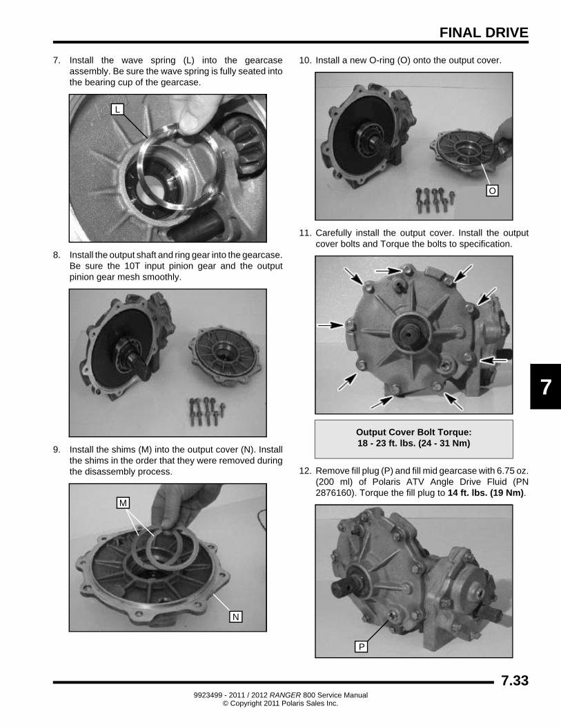
7. Install the wave spring (L) into the gearcase assembly. Be sure the wave spring is fully seated into the bearing cup of the gearcase.
8. Install the output shaft and ring gear into the gearcase. Be sure the 10T input pinion gear and the output pinion gear mesh smoothly.
9. Install the shims (M) into the output cover (N). Install the shims in the order that they were removed during the disassembly process.
10. Install a new O-ring (O) onto the output cover.
11. Carefully install the output cover. Install the output cover bolts and Torque the bolts to specification.
12. Remove fill plug (P) and fill mid gearcase with 6.75 oz. (200 ml) of Polaris ATV Angle Drive Fluid (PN 2876160). Torque the fill plug to 14 ft. lbs. (19 Nm).
L
M
N
Output Cover Bolt Torque:18 - 23 ft. lbs. (24 - 31 Nm)
O
P
7.339923499 - 2011 / 2012 RANGER 800 Service Manual
© Copyright 2011 Polaris Sales Inc.

FINAL DRIVE
Gearcase Installation
1. Install the mid gearcase into the frame.
2. Slide the mid gearcase forward and install the mid propshaft onto the mid gearcase input shaft.
3. Position the mid gearcase and install the (4) mounting bolts. Torque the bolts to specification.
4. Perform the “MID / REAR DRIVE SHAFT - Installation” procedure to reinstall the mid drive shafts.
5. Install the rear propshaft onto the mid gearcase and drive a NEW roll pin into the propshaft yoke.
6. Install the parking brake caliper assembly. Tighten the two mounting bolts in increments and torque to specification.
Mid Gearcase Specifications:
Capacity: 6.75 oz. (200 ml)
Specified Lubricant: ATV Angle Drive Fluid (PN 2876160)
Fill Plug Torque: 14 ft. lbs. (19 Nm)
= T
Mid Gearcase - Mounting Bolts: 30-36 ft. lbs. (41-49 Nm)
Mid Propshaft
Mid Gearcase
30-36 ft. lbs.(41-49 Nm)
= T
Parking Brake Caliper - Mounting Bolts: 18 ft. lbs. (24 Nm)
18 ft. lbs.(24 Nm)
7.349923499 - 2011 / 2012 RANGER 800 Service Manual
© Copyright 2011 Polaris Sales Inc.

FINAL DRIVE
7
Mid Gearcase Exploded View
REF# DESCRIPTION QTY REF# DESCRIPTION QTY
1 Screw (5/16-18 x 1.0) 15 16 Washer, Thrust 2
2 Plug, Square Socket 3 17 Bearing, Plain Flanged 2
3 Seal, Dual Lip 2 18 Gearcase 1
4 Tube, Vent 1/4” Hose 1 19 Bushing 1
5 Cover, Output 1 20 Pinion, 10T 1
6 Shim 1 21 Gear, 26T Output 1
7 Bearing, Ball 1 22 Bearing, Ball 1
8 Gear, Ring 37T 1 23 Shaft, Output Thru 1
9 Shaft, Output 1 24 Gear, 26T Input 1
10 Bearing, Ball 1 25 Cover, Input 1
11 Spring, Wave 1 26 Seal, Triple Lip 1
12 O-Ring 1 27 N/A -
13 Pipe, Knock 4 28 N/A -
14 Seal, Triple Lip 1 29 N/A -
15 Ring, Retaining 2 30 Ring, Hog 2
18-23 ft. lbs.(24-31 Nm)
18-23 ft. lbs.(24-31 Nm)
7.359923499 - 2011 / 2012 RANGER 800 Service Manual
© Copyright 2011 Polaris Sales Inc.

FINAL DRIVE
DRIVE SHAFT SERVICE
Drive Shaft / CV Joint Handling Tips
Care should be exercised during drive shaft removal or when servicing CV joints. Drive shaft components are precision parts.
Cleanliness and following these instructions is very important to ensure proper shaft function and a normal service life.
• The complete drive shaft and joint should be handled by getting hold of the interconnecting shaft to avoid disassembly or potential damage to the drive shaft joints.
• Over-angling of joints beyond their capacity could result in boot or joint damage.
• Make sure surface-ground areas and splines of shaft are protected during handling to avoid damage.
• Do not allow boots to come into contact with sharp edges or hot engine and exhaust components.
• The drive shaft is not to be used as a lever arm to position other suspension components.
• Never use a hammer or sharp tools to remove or to install boot clamps.
• Be sure joints are thoroughly clean and that the proper amount and type of grease is used to refill when joint boots are replaced and when joints are cleaned. Refer to text for grease capacity of CV joints and CV joint boots.
Outer CV Joint / Boot Replacement
1. Use a side cutters to cut and discard the boot clamps.
2. Remove the large end of the boot from the CV joint and slide the boot down the shaft.
3. Clean the grease from the face of the joint.
4. Place the drive shaft in a soft-jawed vise.
5. Using a soft-faced hammer, or brass drift, strike inner race of the joint to drive the joint off the drive shaft. Be sure to tap evenly around the joint to avoid binding.
IMPORTANT: Tap on inner race only!
6. Make sure circlip is on the shaft and not left in the joint.
Brass Drift Shown
Circlip
7.369923499 - 2011 / 2012 RANGER 800 Service Manual
© Copyright 2011 Polaris Sales Inc.

FINAL DRIVE
7
7. Remove the CV boot from the shaft.
IMPORTANT: If the grease in the joint is obviously contaminated with water and/or dirt, the joint should be replaced.
8. Thoroughly clean the joint with an appropriate solvent and dry the joint to prevent any residual solvent from being left in the joint upon reassembly.
9. Visually inspect the joint by tilting the inner race to one side to expose each ball. Severe pitting, galling, play between the ball and its cage window, any cracking or damage to the cage, pitting or galling or chips in raceways call for joint replacement.
NOTE: Shiny areas in ball tracks and on the cage spheres are normal. Do not replace CV joints because parts have polished surfaces. Replace CV joint only if components are cracked, broken, worn or otherwise unserviceable.
10. Clean the splines on the end of the shaft and apply a light coat of grease prior to reassembly.
11. Slide the small boot clamp and boot (small end first) onto the drive shaft and position the boot in it’s groove machined in the shaft.
12. Install a NEW circlip on the end of the shaft.
13. Grease the joint with the special CV joint grease provided in the boot replacement kit. Fill the cavity behind the balls and the splined hole in the joint’s inner race. Pack the ball tracks and outer face flush with grease. Place any remaining grease into the boot.
NOTE: It is very important to use the correct type and quantity of grease by using all the grease included with the boot kit. DO NOT use a substitute grease and DO NOT overfill or under fill the CV joint.
14. Slide the joint onto the drive shaft splines and align the circlip with the lead-in chamfer on the inner race of the joint.
15. Use a soft-faced hammer to tap the joint onto the drive shaft until it locks into place.
16. Pull on joint to make sure it is securely locked in place.
17. Remove excess grease from the CV joint's external surfaces and place the excess grease in the boot.
18. Pull the boot over the joint and position the boot lips into the grooves on the joint housing and shaft. Make sure the boot is not dimpled or collapsed.
CAUTION
Complete disassembly of the CV joint is NOT recommended. The internal components are
precision fit and develop their own characteristic wear patterns. Intermixing the internal
components could result in looseness, binding, and/or premature failure of the joint.
CAUTION
The grease provided in the replacement kit is specially formulated for wear resistance and
durability. DO NOT use substitutes or mix with other lubricants.
Boot Replacement Grease Requirements:
Outer CV Joint Capacity:Front - 74g / Rear - 90g
Grease Only Service Kit: PN 1350047 (50g)
7.379923499 - 2011 / 2012 RANGER 800 Service Manual
© Copyright 2011 Polaris Sales Inc.

FINAL DRIVE
19. Install and tighten the large clamp using the appropriate clamp tool.
20. While pulling out on the CV shaft, fully extend the CV joint and slide a straight O-ring pick or a small slotted screw driver between the small end of the boot and the shaft. This will allow the air pressure to equalize in the CV boot in the position that the joint will spend most of its life. Before you remove your instrument, be sure the small end of the boot is in its correct location on the shaft.
21. Install and tighten the small clamp on the boot using the appropriate clamp tool.
Inner Plunging Joint / Boot Replacement
1. Use a side cutters to cut and discard the boot clamps.
2. Remove the large end of the boot from the plunging joint and slide the boot down the shaft.
3. Clean the grease from the face of the joint.
4. Place the drive shaft in a soft-jawed vise.
5. Using a soft-faced hammer, or brass drift, strike inner race of the joint to drive the joint off the drive shaft. Be sure to tap evenly around the joint to avoid binding.
Axle Boot Clamp Tool: PU-48951or
CV Boot Clamp Pliers: 8700226
Axle Boot Clamp Tool: PU-48951or
CV Boot Clamp Pliers: 8700226
Brass Drift Shown
7.389923499 - 2011 / 2012 RANGER 800 Service Manual
© Copyright 2011 Polaris Sales Inc.

FINAL DRIVE
7
IMPORTANT: Tap on inner race only!
6. Make sure circlip is on the shaft and not left in the joint.
7. Remove the boot from the shaft.
IMPORTANT: If the grease in the joint is obviously contaminated with water and/or dirt, the joint should be replaced.
8. Thoroughly clean the joint with an appropriate solvent and dry the joint to prevent any residual solvent from being left in the joint upon reassembly.
9. Visually inspect joint for damage. Replace if needed.
10. Clean the splines on the end of the shaft and apply a light coat of grease prior to reassembly.
11. Slide the small boot clamp and boot (small end first) onto the drive shaft and position the boot in its groove machined in the shaft.
12. Install a NEW circlip on the end of the shaft.
13. Grease the joint with the special CV joint grease provided in the boot replacement kit. Fill the cavity behind the balls and the splined hole in the joint’s inner race. Pack the ball tracks and outer face flush with grease. Place any remaining grease into the boot.
NOTE: It is very important to use the correct type and quantity of grease by using all the grease included with the boot kit. DO NOT use a substitute grease and DO NOT overfill or under fill the CV joint.
14. Fully compress the joint and push the drive shaft firmly into the inner race.
15. Align the circlip with the lead-in chamfer.
16. Use a soft-faced hammer to tap the joint onto the drive shaft until you reach the end of the splines and the joint locks in place.
CAUTION
Complete disassembly of the plunging joint is NOT recommended. The internal components
are precision fit and develop their own characteristic wear patterns. Intermixing the
internal components could result in looseness, binding, and/or premature failure of the joint.
Circlip
CAUTION
The grease provided in the replacement kit is specially formulated for wear resistance and
durability. DO NOT use substitutes or mix with other lubricants.
Boot Replacement Grease Requirements:
Inner Plunging Joint Capacity:Front - 60g / Rear - 100g
Grease Only Service Kit: PN 1350047 (50g)
7.399923499 - 2011 / 2012 RANGER 800 Service Manual
© Copyright 2011 Polaris Sales Inc.

FINAL DRIVE
17. Pull on the joint to test that the circlip is seated and that the joint is securely fastened to the shaft.
18. Remove excess grease from plunging joint’s external surfaces and place the excess grease in the boot.
19. Pull the boot over the joint and position the boot lips into the grooves on the joint housing and shaft. Make sure the boot is not dimpled or collapsed.
20. Install and tighten the small clamp using the appropriate clamp tool.
21. Pull out on drive shaft to center joint in the housing. Slide a straight O-ring pick or a small slotted screw driver between the large end of the boot and the joint housing and lift up to equalize air pressure in the boot.
22. Position the boot lip in its groove. Install and tighten the large clamp using the appropriate clamp tool.
Drive Shaft Exploded View
Axle Boot Clamp Tool: PU-48951or
CV Boot Clamp Pliers: 8700226
Axle Boot Clamp Tool: PU-48951or
CV Boot Clamp Pliers: 8700226
REAR SHAFT
Grease Capacity74 Grams
Grease Capacity60 Grams
CV Joint
Plunging
Spring Ring
Gear SideBoot Kit
Wheel SideBoot Kit
Joint
FRONT SHAFT
Grease Capacity90 Grams
Grease Capacity100 Grams
CV Joint
Plunging
Spring Ring
Gear SideBoot Kit
Wheel SideBoot Kit
Joint
Rear 4x4 Shown
7.409923499 - 2011 / 2012 RANGER 800 Service Manual
© Copyright 2011 Polaris Sales Inc.

FINAL DRIVE
7
REAR PROPSHAFT (6X6)
Removal
1. Drive the roll pin from the rear propshaft yoke located at the mid gearcase.
2. Remove the parking brake caliper assembly from the caliper mount bracket to allow the rear propshaft to slide back on the rear gearcase input shaft.
3. Slide the rear propshaft back on the rear gearcase input shaft, remove the propshaft from the mid gearcase and remove the propshaft from the vehicle.
Installation
1. Install the rear propshaft onto the rear gearcase input shaft.
2. Align the rear propshaft pin hole with the pin hole on the mid gearcase rear output shaft.
3. Slide the rear propshaft forward onto the mid gearcase rear output shaft and drive a NEW roll pin into the propshaft yoke.
4. Install the parking brake caliper assembly. Tighten the two mounting bolts in increments and torque to specification.
Roll Pin Removal Tool (PN 2872608)
Roll PinRemoval Tool
Remove
= T
Parking Brake Caliper - Mounting Bolts: 18 ft. lbs. (24 Nm)
18 ft. lbs.(24 Nm)
7.419923499 - 2011 / 2012 RANGER 800 Service Manual
© Copyright 2011 Polaris Sales Inc.
FINAL DRIVE
REAR GEARCASE (6X6)
General Operation
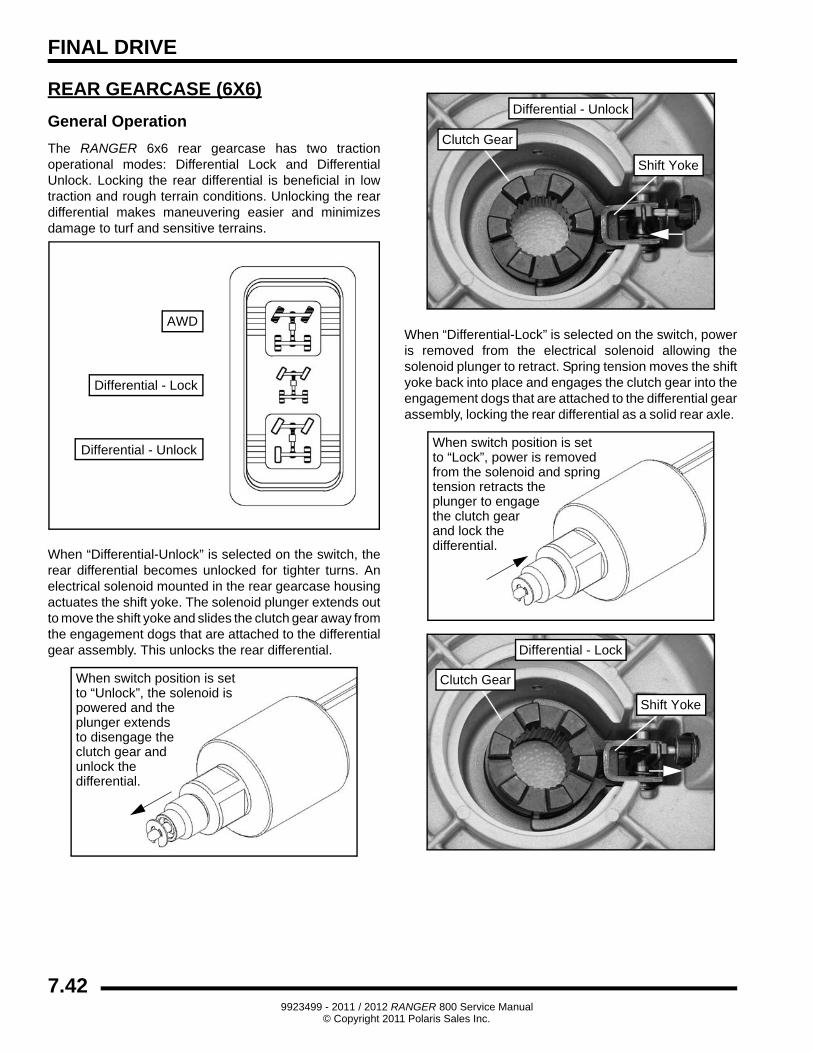
The RANGER 6x6 rear gearcase has two traction operational modes: Differential Lock and Differential Unlock. Locking the rear differential is beneficial in low traction and rough terrain conditions. Unlocking the rear differential makes maneuvering easier and minimizes damage to turf and sensitive terrains.
When “Differential-Unlock” is selected on the switch, the rear differential becomes unlocked for tighter turns. An electrical solenoid mounted in the rear gearcase housing actuates the shift yoke. The solenoid plunger extends out to move the shift yoke and slides the clutch gear away from the engagement dogs that are attached to the differential gear assembly. This unlocks the rear differential.
When “Differential-Lock” is selected on the switch, power is removed from the electrical solenoid allowing the solenoid plunger to retract. Spring tension moves the shift yoke back into place and engages the clutch gear into the engagement dogs that are attached to the differential gear assembly, locking the rear differential as a solid rear axle.
AWD
Differential - Lock
Differential - Unlock
When switch position is setto “Unlock”, the solenoid ispowered and the plunger extendsto disengage theclutch gear andunlock thedifferential.
Clutch Gear
Shift Yoke
Differential - Unlock
When switch position is setto “Lock”, power is removedfrom the solenoid and spring tension retracts theplunger to engagethe clutch gearand lock thedifferential.
Shift Yoke
Clutch Gear
Differential - Lock
7.429923499 - 2011 / 2012 RANGER 800 Service Manual
© Copyright 2011 Polaris Sales Inc.

FINAL DRIVE
7
When the clutch gear is unlocked the rear drive shafts are dependent on the differential allowing tighter turns. When it’s locked it becomes a solid rear axle increasing traction.
Gearcase Removal
1. Follow the “MID / REAR DRIVE SHAFT - Removal” procedure to remove the rear drive shafts from each side of the rear gearcase.
2. Disconnect the differential solenoid 2-wire harness.
3. Completely drain the lubricant from the rear gearcase.
4. Remove the (4) bolts that secure the rear gearcase to the frame.
5. Remove the (3) fasteners retaining the parking brake caliper bracket to the rear gearcase and carefully pull the rear gear case assembly from the frame. Allow the rear propshaft to slide off of the rear gearcase shaft.
Clutch Gear
Differential
IRS AxleClutch Gear
Unlocked
Locked Mode
Unlocked Mode
Axle Shaft
Clutch Gear
Locked
Axle Shaft
Axle ShaftAxle Shaft
Drain Plug
Remove the (2)fasteners from each side.
Propshaft
Bracket
(3)
7.439923499 - 2011 / 2012 RANGER 800 Service Manual
© Copyright 2011 Polaris Sales Inc.

FINAL DRIVE
Gearcase Disassembly
IMPORTANT: The pinion gear assembly is NOT intended to be disassembled from the case, as it requires special OEM tooling in order to properly reassemble. If there is any damage to the pinion gear, bearings or case, the assembly must be replaced. Pinion and ring gear shimming information is NOT provided due to OEM manufacturing requirements.
1. Remove the differential solenoid from the gearcase cover if servicing the solenoid, shift lever, shift lever spring, or shift yoke. If none of these items are being serviced, the solenoid can remain installed in the gearcase cover.
2. Remove the (7) bolts that secure the cover to the housing.
3. Remove the differential assembly from the housing.
4. Inspect the bevel gear for chipped, worn, or broken teeth.
5. Remove the small bearing from the differential assembly. Inspect the bearing for smoothness and wear.
Remove Cover Bolts
Inspect Teeth
7.449923499 - 2011 / 2012 RANGER 800 Service Manual
© Copyright 2011 Polaris Sales Inc.
FINAL DRIVE
7
6. Remove the shims from the differential assembly. Be sure to keep the shims together for reassembly.
7. Remove the large bearing from the differential assembly. Inspect the bearing for smoothness and wear.
8. Remove the shims from the differential assembly. Be sure to keep the shims together for reassembly.
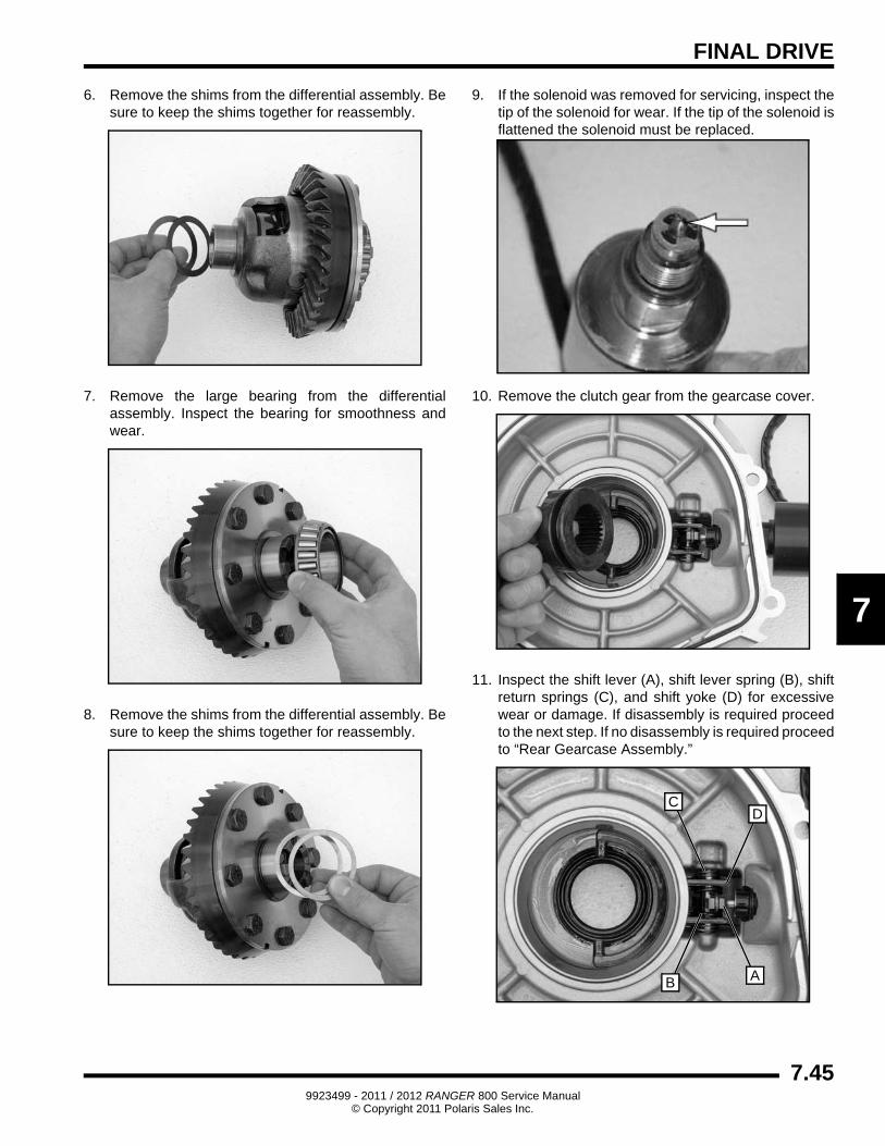
9. If the solenoid was removed for servicing, inspect the tip of the solenoid for wear. If the tip of the solenoid is flattened the solenoid must be replaced.
10. Remove the clutch gear from the gearcase cover.
11. Inspect the shift lever (A), shift lever spring (B), shift return springs (C), and shift yoke (D) for excessive wear or damage. If disassembly is required proceed to the next step. If no disassembly is required proceed to “Rear Gearcase Assembly.”
AB
CD
7.459923499 - 2011 / 2012 RANGER 800 Service Manual
© Copyright 2011 Polaris Sales Inc.

FINAL DRIVE
12. Loosen the lock assembly pin.
13. Remove the pin from the gearcase cover.
14. Carefully remove the shift yoke assembly from the gearcase cover.
15. Inspect the shift lever (A), shift lever spring (B), shift return springs (C), shift yoke (D), and lock pin bushing (E). Inspect the components for excessive wear or damage and replace as needed.
Rear Gearcase Assembly
NOTE: Grease all seals and O-rings with Polaris All Season Grease (PN 2871322) upon assembly.
1. Remove the pinion shaft oil seal using a seal puller and replace with a new seal.
NOTE: The pinion gear assembly is NOT intended to be disassembled from the case, as it requires special OEM tooling in order to properly reassemble. If there is any damage to the pinion gear, bearings or case, the assembly must be replaced.
A
BC
C
D
E
7.469923499 - 2011 / 2012 RANGER 800 Service Manual
© Copyright 2011 Polaris Sales Inc.

FINAL DRIVE
7
2. Replace the drive shaft oil seals located in the main gearcase and gearcase cover
3. Replace all worn components.
4. Install the original shims (A) onto the differential assembly (B) on both sides. Install the bearings (C), replace with new bearings if needed.
5. Install the differential assembly into the carrier housing.
Do Not Disassemble.Replace as an assemblyif damaged or worn.
B
A
C
B
A
C
7.479923499 - 2011 / 2012 RANGER 800 Service Manual
© Copyright 2011 Polaris Sales Inc.

FINAL DRIVE
6. If previously removed; assembly the shift lever (A), shift lever spring (B), shift return springs (C), shift yoke (D), and lock pin bushing (E).
7. Carefully install the shift yoke assembly into the gearcase cover.
8. Install the lock assembly pin and tighten.
9. Install the new lightly greased O-ring onto the carrier cover.
10. Assemble the gearcase halves and install the (7) bolts that secure the cover to the housing. Torque the bolts in a criss cross pattern to 25-35 ft. lbs. (34-48 Nm).
11. If previously removed, install the differential solenoid into the carrier cover. Torque solenoid to 30-40 ft. lbs. (41-54 Nm).
A
BC
C
D
E
O-Ring
25-35 ft. lbs.(34-48 Nm)
30-40 ft. lbs.(41-54 Nm)
7.489923499 - 2011 / 2012 RANGER 800 Service Manual
© Copyright 2011 Polaris Sales Inc.

FINAL DRIVE
7
Rear Gearcase Installation
1. Place rear gearcase assembly into the frame. Slide the rear propshaft onto the rear gearcase input shaft.
2. Install the (4) gearcase mounting fasteners and torque the fasteners to 40 ft. lbs. (54 Nm).
3. Install the parking brake caliper bracket fasteners and torque the fasteners to 17 ft. lbs. (23 Nm).
4. Connect the differential solenoid 2-wire harness.
5. Follow the “MID / REAR DRIVE SHAFT - Installation” procedure to reinstall the rear drive shafts.
6. Add Polaris ATV Angle Drive Fluid (PN 2876160) to rear carrier. Refer to maintenance information in Chapter 2 for more details. Torque drain plug to 30-45 in. lbs. (3-5 Nm). Torque fill plug to 40-50 ft. lbs. (54-68 Nm).
=
Rear Gearcase Lubricant / Capacity:ATV Angle Drive Fluid / 18 fl. oz. (532 ml)
40 ft. lbs.(54 Nm)
17 ft. lbs.23 (Nm)
Propshaft
Bracket
Drain PlugFill Plug40-50 ft. lbs.(54-68 Nm)
30-45 in. lbs.(3-5 Nm)
7.499923499 - 2011 / 2012 RANGER 800 Service Manual
© Copyright 2011 Polaris Sales Inc.
FINAL DRIVE
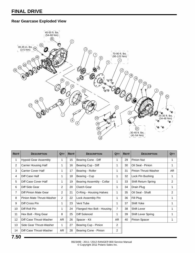
Rear Gearcase Exploded View
REF# DESCRIPTION QTY REF# DESCRIPTION QTY REF# DESCRIPTION QTY
1 Hypoid Gear Assembly 1 15 Bearing Cone - Diff 1 29 Pinion Nut 1
2 Carrier Housing Half 1 16 Bearing Cup - Diff 1 30 Oil Seal - Pinion 1
3 Carrier Cover Half 1 17 Bearing - Roller 1 31 Pinion Thrust-Washer AR
4 Diff Case Half 1 18 Bearing - Cup 1 32 Lock Pin Bushing 1
5 Diff Case Cover Half 1 19 Bearing Assembly - Collar 1 33 Shift Return Spring 2
6 Diff Side Gear 2 20 Clutch Gear 1 34 Drain Plug 1
7 Diff Pinion Mate Gear 2 21 O-Ring - Housing Halves 1 35 Oil Seal - Shaft 2
8 Pinion Mate Thrust-Washer 2 22 Lock Assembly Pin 1 36 Fill Plug 1
9 Diff Cross Pin 1 23 Vent Tube 1 37 Shift Yoke 1
10 Diff Roll Pin 1 24 Flanged Hex Bolt - Housing 7 38 Shift Lever 1
11 Hex Bolt - Ring Gear 8 25 Diff Solenoid 1 39 Shift Lever Spring 1
12 Diff Case Thrust-Washer AR 26 Spacer - Kit AR 40 Pinion Spacer 1
13 Side Gear Thrust-Washer 1 27 Bearing Cup - Pinion 2
14 Diff Case Thrust-Washer AR 28 Bearing Cone - Pinion 2
30-45 in. lbs.(3-5 Nm)
40-50 ft. lbs.(54-68 Nm)
25-35 ft. lbs.(34-48 Nm)
30-40 ft. lbs.(41-54 Nm)
70-90 ft. lbs.(95-122 Nm)
7.509923499 - 2011 / 2012 RANGER 800 Service Manual
© Copyright 2011 Polaris Sales Inc.


![Technical Bulletin - Polaris - Polaris 9300 Sport & Polaris 9300xi Sport[1]](https://img.pdfslide.us/doc/110x75/553b235d4a7959d8258b463f/technical-bulletin-polaris-polaris-9300-sport-polaris-9300xi-sport1.jpg)