Embed Size (px)
Citation preview
BRAKES
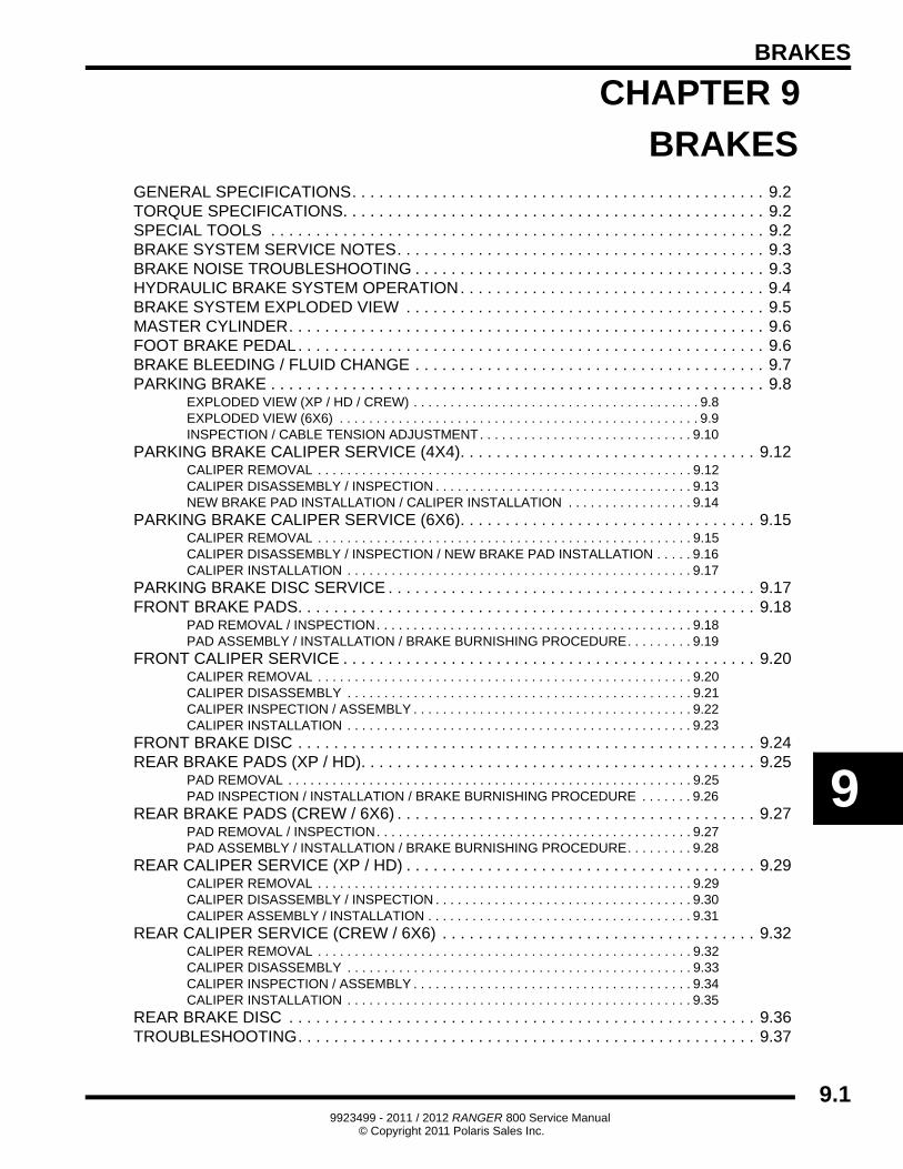
CHAPTER 9
BRAKES
9
GENERAL SPECIFICATIONS. . . . . . . . . . . . . . . . . . . . . . . . . . . . . . . . . . . . . . . . . . . . . . 9.2TORQUE SPECIFICATIONS. . . . . . . . . . . . . . . . . . . . . . . . . . . . . . . . . . . . . . . . . . . . . . . 9.2SPECIAL TOOLS . . . . . . . . . . . . . . . . . . . . . . . . . . . . . . . . . . . . . . . . . . . . . . . . . . . . . . . 9.2BRAKE SYSTEM SERVICE NOTES. . . . . . . . . . . . . . . . . . . . . . . . . . . . . . . . . . . . . . . . . 9.3BRAKE NOISE TROUBLESHOOTING . . . . . . . . . . . . . . . . . . . . . . . . . . . . . . . . . . . . . . . 9.3HYDRAULIC BRAKE SYSTEM OPERATION. . . . . . . . . . . . . . . . . . . . . . . . . . . . . . . . . . 9.4BRAKE SYSTEM EXPLODED VIEW . . . . . . . . . . . . . . . . . . . . . . . . . . . . . . . . . . . . . . . . 9.5MASTER CYLINDER. . . . . . . . . . . . . . . . . . . . . . . . . . . . . . . . . . . . . . . . . . . . . . . . . . . . . 9.6FOOT BRAKE PEDAL. . . . . . . . . . . . . . . . . . . . . . . . . . . . . . . . . . . . . . . . . . . . . . . . . . . . 9.6BRAKE BLEEDING / FLUID CHANGE . . . . . . . . . . . . . . . . . . . . . . . . . . . . . . . . . . . . . . . 9.7PARKING BRAKE . . . . . . . . . . . . . . . . . . . . . . . . . . . . . . . . . . . . . . . . . . . . . . . . . . . . . . . 9.8
EXPLODED VIEW (XP / HD / CREW) . . . . . . . . . . . . . . . . . . . . . . . . . . . . . . . . . . . . . . . 9.8EXPLODED VIEW (6X6) . . . . . . . . . . . . . . . . . . . . . . . . . . . . . . . . . . . . . . . . . . . . . . . . . 9.9INSPECTION / CABLE TENSION ADJUSTMENT. . . . . . . . . . . . . . . . . . . . . . . . . . . . . 9.10
PARKING BRAKE CALIPER SERVICE (4X4). . . . . . . . . . . . . . . . . . . . . . . . . . . . . . . . . 9.12CALIPER REMOVAL . . . . . . . . . . . . . . . . . . . . . . . . . . . . . . . . . . . . . . . . . . . . . . . . . . . 9.12CALIPER DISASSEMBLY / INSPECTION . . . . . . . . . . . . . . . . . . . . . . . . . . . . . . . . . . . 9.13NEW BRAKE PAD INSTALLATION / CALIPER INSTALLATION . . . . . . . . . . . . . . . . . 9.14
PARKING BRAKE CALIPER SERVICE (6X6). . . . . . . . . . . . . . . . . . . . . . . . . . . . . . . . . 9.15CALIPER REMOVAL . . . . . . . . . . . . . . . . . . . . . . . . . . . . . . . . . . . . . . . . . . . . . . . . . . . 9.15CALIPER DISASSEMBLY / INSPECTION / NEW BRAKE PAD INSTALLATION . . . . . 9.16CALIPER INSTALLATION . . . . . . . . . . . . . . . . . . . . . . . . . . . . . . . . . . . . . . . . . . . . . . . 9.17
PARKING BRAKE DISC SERVICE . . . . . . . . . . . . . . . . . . . . . . . . . . . . . . . . . . . . . . . . . 9.17FRONT BRAKE PADS. . . . . . . . . . . . . . . . . . . . . . . . . . . . . . . . . . . . . . . . . . . . . . . . . . . 9.18
PAD REMOVAL / INSPECTION. . . . . . . . . . . . . . . . . . . . . . . . . . . . . . . . . . . . . . . . . . . 9.18PAD ASSEMBLY / INSTALLATION / BRAKE BURNISHING PROCEDURE. . . . . . . . . 9.19
FRONT CALIPER SERVICE . . . . . . . . . . . . . . . . . . . . . . . . . . . . . . . . . . . . . . . . . . . . . . 9.20CALIPER REMOVAL . . . . . . . . . . . . . . . . . . . . . . . . . . . . . . . . . . . . . . . . . . . . . . . . . . . 9.20CALIPER DISASSEMBLY . . . . . . . . . . . . . . . . . . . . . . . . . . . . . . . . . . . . . . . . . . . . . . . 9.21CALIPER INSPECTION / ASSEMBLY . . . . . . . . . . . . . . . . . . . . . . . . . . . . . . . . . . . . . . 9.22CALIPER INSTALLATION . . . . . . . . . . . . . . . . . . . . . . . . . . . . . . . . . . . . . . . . . . . . . . . 9.23
FRONT BRAKE DISC . . . . . . . . . . . . . . . . . . . . . . . . . . . . . . . . . . . . . . . . . . . . . . . . . . . 9.24REAR BRAKE PADS (XP / HD). . . . . . . . . . . . . . . . . . . . . . . . . . . . . . . . . . . . . . . . . . . . 9.25
PAD REMOVAL . . . . . . . . . . . . . . . . . . . . . . . . . . . . . . . . . . . . . . . . . . . . . . . . . . . . . . . 9.25PAD INSPECTION / INSTALLATION / BRAKE BURNISHING PROCEDURE . . . . . . . 9.26
REAR BRAKE PADS (CREW / 6X6) . . . . . . . . . . . . . . . . . . . . . . . . . . . . . . . . . . . . . . . . 9.27PAD REMOVAL / INSPECTION. . . . . . . . . . . . . . . . . . . . . . . . . . . . . . . . . . . . . . . . . . . 9.27PAD ASSEMBLY / INSTALLATION / BRAKE BURNISHING PROCEDURE. . . . . . . . . 9.28
REAR CALIPER SERVICE (XP / HD) . . . . . . . . . . . . . . . . . . . . . . . . . . . . . . . . . . . . . . . 9.29CALIPER REMOVAL . . . . . . . . . . . . . . . . . . . . . . . . . . . . . . . . . . . . . . . . . . . . . . . . . . . 9.29CALIPER DISASSEMBLY / INSPECTION . . . . . . . . . . . . . . . . . . . . . . . . . . . . . . . . . . . 9.30CALIPER ASSEMBLY / INSTALLATION . . . . . . . . . . . . . . . . . . . . . . . . . . . . . . . . . . . . 9.31
REAR CALIPER SERVICE (CREW / 6X6) . . . . . . . . . . . . . . . . . . . . . . . . . . . . . . . . . . . 9.32CALIPER REMOVAL . . . . . . . . . . . . . . . . . . . . . . . . . . . . . . . . . . . . . . . . . . . . . . . . . . . 9.32CALIPER DISASSEMBLY . . . . . . . . . . . . . . . . . . . . . . . . . . . . . . . . . . . . . . . . . . . . . . . 9.33CALIPER INSPECTION / ASSEMBLY . . . . . . . . . . . . . . . . . . . . . . . . . . . . . . . . . . . . . . 9.34CALIPER INSTALLATION . . . . . . . . . . . . . . . . . . . . . . . . . . . . . . . . . . . . . . . . . . . . . . . 9.35
REAR BRAKE DISC . . . . . . . . . . . . . . . . . . . . . . . . . . . . . . . . . . . . . . . . . . . . . . . . . . . . 9.36TROUBLESHOOTING. . . . . . . . . . . . . . . . . . . . . . . . . . . . . . . . . . . . . . . . . . . . . . . . . . . 9.37
9.19923499 - 2011 / 2012 RANGER 800 Service Manual
© Copyright 2011 Polaris Sales Inc.
BRAKES
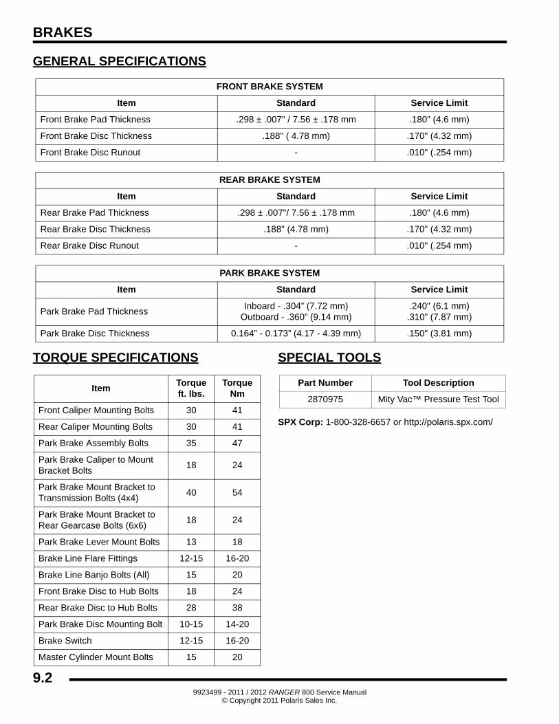
GENERAL SPECIFICATIONS
TORQUE SPECIFICATIONS SPECIAL TOOLS
SPX Corp: 1-800-328-6657 or http://polaris.spx.com/
FRONT BRAKE SYSTEM
Item Standard Service Limit
Front Brake Pad Thickness .298 ± .007" / 7.56 ± .178 mm .180" (4.6 mm)
Front Brake Disc Thickness .188" ( 4.78 mm) .170" (4.32 mm)
Front Brake Disc Runout - .010" (.254 mm)
REAR BRAKE SYSTEM
Item Standard Service Limit
Rear Brake Pad Thickness .298 ± .007"/ 7.56 ± .178 mm .180" (4.6 mm)
Rear Brake Disc Thickness .188" (4.78 mm) .170" (4.32 mm)
Rear Brake Disc Runout - .010" (.254 mm)
PARK BRAKE SYSTEM
Item Standard Service Limit
Park Brake Pad ThicknessInboard - .304” (7.72 mm)
Outboard - .360” (9.14 mm).240" (6.1 mm).310” (7.87 mm)
Park Brake Disc Thickness 0.164” - 0.173” (4.17 - 4.39 mm) .150" (3.81 mm)
ItemTorqueft. lbs.
TorqueNm
Front Caliper Mounting Bolts 30 41
Rear Caliper Mounting Bolts 30 41
Park Brake Assembly Bolts 35 47
Park Brake Caliper to Mount Bracket Bolts
18 24
Park Brake Mount Bracket to Transmission Bolts (4x4)
40 54
Park Brake Mount Bracket to Rear Gearcase Bolts (6x6)
18 24
Park Brake Lever Mount Bolts 13 18
Brake Line Flare Fittings 12-15 16-20
Brake Line Banjo Bolts (All) 15 20
Front Brake Disc to Hub Bolts 18 24
Rear Brake Disc to Hub Bolts 28 38
Park Brake Disc Mounting Bolt 10-15 14-20
Brake Switch 12-15 16-20
Master Cylinder Mount Bolts 15 20
Part Number Tool Description
2870975 Mity Vac™ Pressure Test Tool
9.29923499 - 2011 / 2012 RANGER 800 Service Manual
© Copyright 2011 Polaris Sales Inc.
BRAKES
9
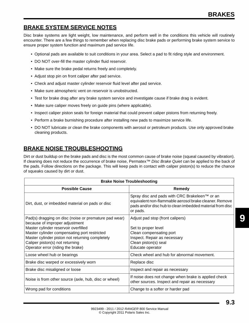
BRAKE SYSTEM SERVICE NOTESDisc brake systems are light weight, low maintenance, and perform well in the conditions this vehicle will routinely encounter. There are a few things to remember when replacing disc brake pads or performing brake system service to ensure proper system function and maximum pad service life.
• Optional pads are available to suit conditions in your area. Select a pad to fit riding style and environment.
• DO NOT over-fill the master cylinder fluid reservoir.
• Make sure the brake pedal returns freely and completely.
• Adjust stop pin on front caliper after pad service.
• Check and adjust master cylinder reservoir fluid level after pad service.
• Make sure atmospheric vent on reservoir is unobstructed.
• Test for brake drag after any brake system service and investigate cause if brake drag is evident.
• Make sure caliper moves freely on guide pins (where applicable).
• Inspect caliper piston seals for foreign material that could prevent caliper pistons from returning freely.
• Perform a brake burnishing procedure after installing new pads to maximize service life.
• DO NOT lubricate or clean the brake components with aerosol or petroleum products. Use only approved brake cleaning products.
BRAKE NOISE TROUBLESHOOTINGDirt or dust buildup on the brake pads and disc is the most common cause of brake noise (squeal caused by vibration). If cleaning does not reduce the occurrence of brake noise, Permatex™ Disc Brake Quiet can be applied to the back of the pads. Follow directions on the package. This will keep pads in contact with caliper piston(s) to reduce the chance of squeaks caused by dirt or dust.
Brake Noise Troubleshooting
Possible Cause Remedy
Dirt, dust, or imbedded material on pads or disc
Spray disc and pads with CRC Brakeleen™ or an equivalent non-flammable aerosol brake cleaner. Remove pads and/or disc hub to clean imbedded material from disc or pads.
Pad(s) dragging on disc (noise or premature pad wear) because of improper adjustmentMaster cylinder reservoir overfilledMaster cylinder compensating port restrictedMaster cylinder piston not returning completelyCaliper piston(s) not returningOperator error (riding the brake)
Adjust pad stop (front calipers)Set to proper levelClean compensating portInspect. Repair as necessaryClean piston(s) seal Educate operator
Loose wheel hub or bearings Check wheel and hub for abnormal movement.
Brake disc warped or excessively worn Replace disc
Brake disc misaligned or loose Inspect and repair as necessary
Noise is from other source (axle, hub, disc or wheel)If noise does not change when brake is applied check other sources. Inspect and repair as necessary
Wrong pad for conditions Change to a softer or harder pad
9.39923499 - 2011 / 2012 RANGER 800 Service Manual
© Copyright 2011 Polaris Sales Inc.
BRAKES
HYDRAULIC BRAKE SYSTEM OPERATION
The Polaris brake system consists of the following components or assemblies: brake pedal, master cylinder, hydraulic brake lines, brake calipers, brake pads, and brake discs, which are secured to the drive line.
When the foot activated brake lever is applied it applies pressure on the piston within the master cylinder. As the master cylinder piston moves inward it closes a small opening (compensating port) within the cylinder and starts to build pressure within the brake system. As the pressure within the system is increased, the pistons located in the brake calipers move outward and apply pressure to the moveable brake pads. These pads contact the brake discs and move the calipers in their floating bracket, pulling the stationary side pads into the brake discs. The resulting friction reduces brake disc and vehicle speed.
The friction applied to the brake pads will cause the pads to wear. As these pads wear, the piston within the caliper moves further outward and becomes self adjusting. Fluid from the reservoir fills the additional area created when the caliper piston moves outward.
Brake fluid level is critical to proper system operation. Too little fluid will allow air to enter the system and cause the brakes to feel spongy. Too much fluid could cause brakes to drag due to fluid expansion.
Located within the master cylinder is the compensating port which is opened and closed by the master cylinder piston assembly. As the temperature within the hydraulic system changes, this port compensates for fluid expansion or contraction. Due to the high temperatures created within the system during heavy braking, it is very important that the master cylinder reservoir have adequate space to allow for fluid expansion. Never overfill the reservoir! Do not fill the reservoir beyond the MAX LEVEL line!
When servicing Polaris brake systems use only Polaris DOT 4 Brake Fluid (PN 2872189). WARNING: Once a bottle is opened, use what is necessary and discard the rest in accordance with local laws. Do not store or use a partial bottle of brake fluid. Brake fluid is hygroscopic, meaning it rapidly absorbs moisture. This causes the boiling temperature of the brake fluid to drop, which can lead to early brake fade and the possibility of serious injury.
9.49923499 - 2011 / 2012 RANGER 800 Service Manual
© Copyright 2011 Polaris Sales Inc.
BRAKES
9
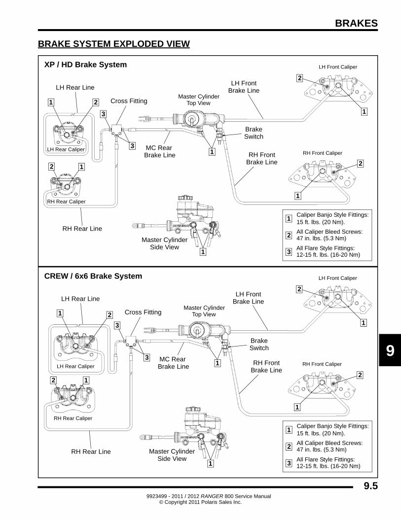
BRAKE SYSTEM EXPLODED VIEW
Caliper Banjo Style Fittings:15 ft. lbs. (20 Nm).
All Caliper Bleed Screws:47 in. lbs. (5.3 Nm)
Master CylinderCross Fitting
MC Rear Brake Line
RH Rear Line
RH Rear Caliper
RH FrontBrake Line
RH Front Caliper
Master Cylinder
LH Front
LH Rear Caliper
LH Front Caliper
Brake Line
1
2
12
3All Flare Style Fittings:12-15 ft. lbs. (16-20 Nm)
3
1
1
2
2
1
Side View1
3
XP / HD Brake System
1 2
LH Rear Line
BrakeSwitch
Top View
Caliper Banjo Style Fittings:15 ft. lbs. (20 Nm).
All Caliper Bleed Screws:47 in. lbs. (5.3 Nm)
Master Cylinder
MC Rear Brake Line
RH Rear Line
RH Rear Caliper
RH FrontBrake Line
RH Front Caliper
Brake
Master Cylinder
LH Front
LH Rear Caliper
LH Front Caliper
Brake LineLH Rear Line
1
2
12
3All Flare Style Fittings:12-15 ft. lbs. (16-20 Nm)
3
1
1
2
2
Switch
Side View
CREW / 6x6 Brake System
1 2
3
Cross Fitting
1
1
Top View
9.59923499 - 2011 / 2012 RANGER 800 Service Manual
© Copyright 2011 Polaris Sales Inc.
BRAKES
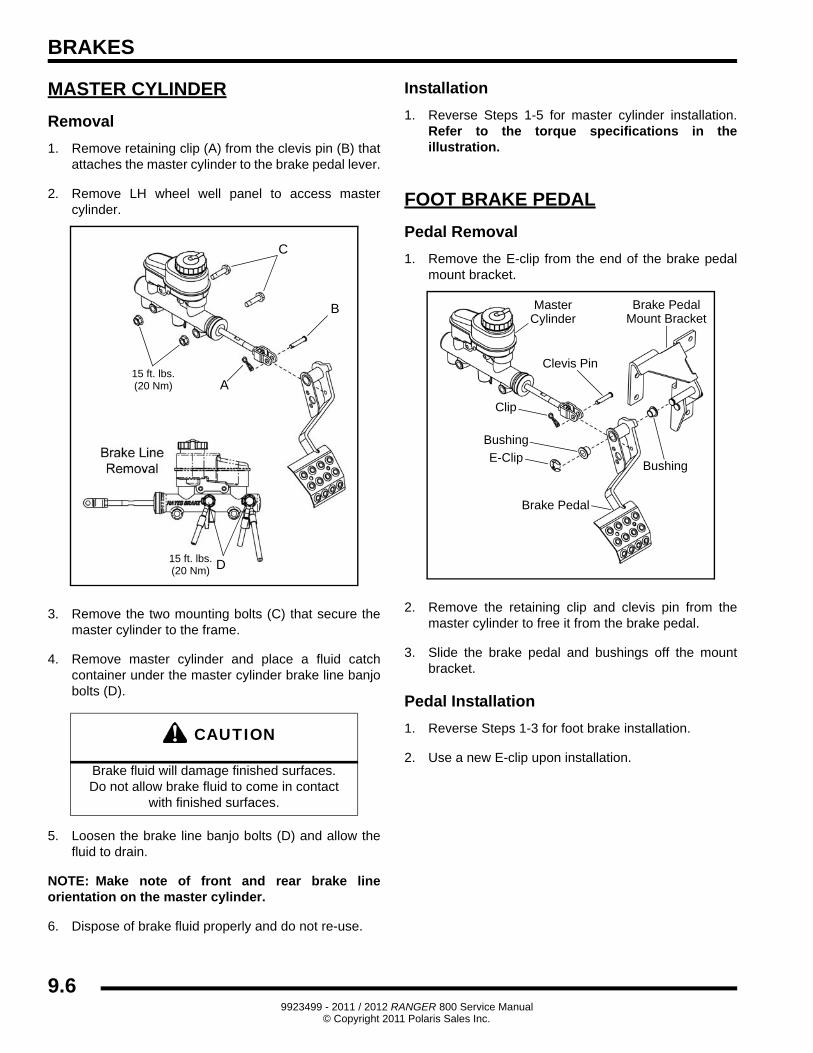
MASTER CYLINDER
Removal
1. Remove retaining clip (A) from the clevis pin (B) that attaches the master cylinder to the brake pedal lever.
2. Remove LH wheel well panel to access master cylinder.
3. Remove the two mounting bolts (C) that secure the master cylinder to the frame.
4. Remove master cylinder and place a fluid catch container under the master cylinder brake line banjo bolts (D).
5. Loosen the brake line banjo bolts (D) and allow the fluid to drain.
NOTE: Make note of front and rear brake line orientation on the master cylinder.
6. Dispose of brake fluid properly and do not re-use.
Installation
1. Reverse Steps 1-5 for master cylinder installation. Refer to the torque specifications in the illustration.
FOOT BRAKE PEDAL
Pedal Removal
1. Remove the E-clip from the end of the brake pedal mount bracket.
2. Remove the retaining clip and clevis pin from the master cylinder to free it from the brake pedal.
3. Slide the brake pedal and bushings off the mount bracket.
Pedal Installation
1. Reverse Steps 1-3 for foot brake installation.
2. Use a new E-clip upon installation.
CAUTION
Brake fluid will damage finished surfaces.Do not allow brake fluid to come in contact
with finished surfaces.
15 ft. lbs.(20 Nm) D
A
B
C
15 ft. lbs.(20 Nm)
Bushing
Clip
Clevis Pin
Brake Pedal
Brake PedalMaster
Bushing
Mount BracketCylinder
E-Clip
9.69923499 - 2011 / 2012 RANGER 800 Service Manual
© Copyright 2011 Polaris Sales Inc.
BRAKES
9
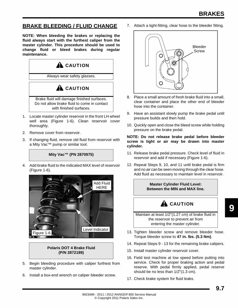
BRAKE BLEEDING / FLUID CHANGE
NOTE: When bleeding the brakes or replacing the fluid always start with the furthest caliper from the master cylinder. This procedure should be used to change fluid or bleed brakes during regular maintenance.
1. Locate master cylinder reservoir in the front LH wheel well area (Figure 1-6). Clean reservoir cover thoroughly.
2. Remove cover from reservoir.
3. If changing fluid, remove old fluid from reservoir with a Mity Vac™ pump or similar tool.
4. Add brake fluid to the indicated MAX level of reservoir (Figure 1-6).
5. Begin bleeding procedure with caliper furthest from master cylinder.
6. Install a box-end wrench on caliper bleeder screw.
7. Attach a tight-fitting, clear hose to the bleeder fitting.
8. Place a small amount of fresh brake fluid into a small, clear container and place the other end of bleeder hose into the container.
9. Have an assistant slowly pump the brake pedal until pressure builds and then hold.
10. Quickly open and close the bleed screw while holding pressure on the brake pedal.
NOTE: Do not release brake pedal before bleeder screw is tight or air may be drawn into master cylinder.
11. Release brake pedal pressure. Check level of fluid in reservoir and add if necessary (Figure 1-6).
12. Repeat Steps 9, 10, and 11 until brake pedal is firm and no air can be seen moving through the clear hose. Add fluid as necessary to maintain level in reservoir.
13. Tighten bleeder screw and remove bleeder hose. Torque bleeder screw to 47 in. lbs. (5.3 Nm).
14. Repeat Steps 9 - 13 for the remaining brake calipers.
15. Install master cylinder reservoir cover.
16. Field test machine at low speed before putting into service. Check for proper braking action and pedal reserve. With pedal firmly applied, pedal reserve should be no less than 1/2"(1.3 cm).
17. Check brake system for fluid leaks.
CAUTION
Always wear safety glasses.
CAUTION
Brake fluid will damage finished surfaces.Do not allow brake fluid to come in contact
with finished surfaces.
Mity Vac™ (PN 2870975)
Polaris DOT 4 Brake Fluid(P/N 2872189)
Level Indicator
Add FluidHERE
Figure 1-6
Master Cylinder Fluid Level:Between the MIN and MAX line.
CAUTION
Maintain at least 1/2"(1.27 cm) of brake fluid in the reservoir to prevent air from
entering the master cylinder.
BleederScrew
9.79923499 - 2011 / 2012 RANGER 800 Service Manual
© Copyright 2011 Polaris Sales Inc.
BRAKES
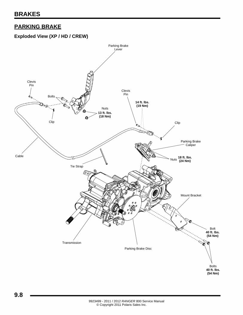
PARKING BRAKE
Exploded View (XP / HD / CREW)
Parking BrakeLever
Nuts
Clip
Cable
Clevis
Parking BrakeCaliper
Mount Bracket
Bolt
Bolts
Pin
ClevisPin
Clip
Bolts
Nuts
Parking Brake Disc
Transmission
13 ft. lbs.(18 Nm)
14 ft. lbs.(19 Nm)
40 ft. lbs.(54 Nm)
18 ft. lbs.(24 Nm)
Tie Strap
40 ft. lbs.(54 Nm)
9.89923499 - 2011 / 2012 RANGER 800 Service Manual
© Copyright 2011 Polaris Sales Inc.
BRAKES
9
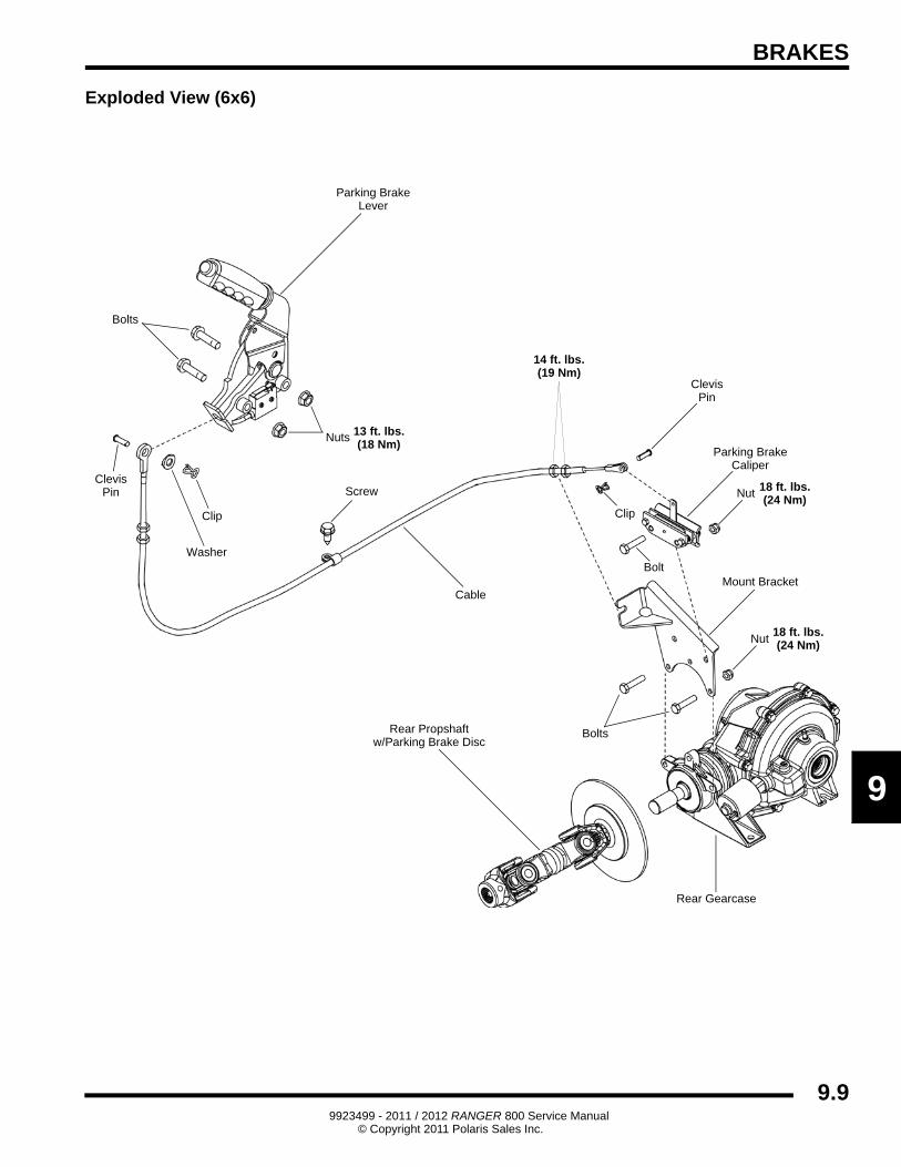
Exploded View (6x6)
Parking BrakeLever
Nuts
Washer
Clip
Screw
Cable
Clevis
Parking BrakeCaliper
Mount BracketBolt
Bolts
Pin
ClevisPin
Clip
Nut
Bolts
Nut
Rear Propshaftw/Parking Brake Disc
Rear Gearcase
13 ft. lbs.(18 Nm)
14 ft. lbs.(19 Nm)
18 ft. lbs.(24 Nm)
18 ft. lbs.(24 Nm)
9.99923499 - 2011 / 2012 RANGER 800 Service Manual
© Copyright 2011 Polaris Sales Inc.
BRAKES
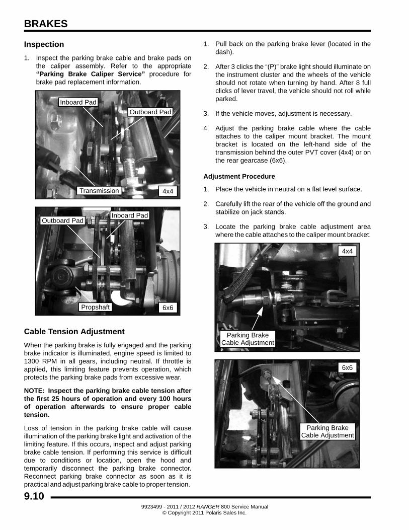
Inspection
1. Inspect the parking brake cable and brake pads on the caliper assembly. Refer to the appropriate “Parking Brake Caliper Service” procedure for brake pad replacement information.
Cable Tension Adjustment
When the parking brake is fully engaged and the parking brake indicator is illuminated, engine speed is limited to 1300 RPM in all gears, including neutral. If throttle is applied, this limiting feature prevents operation, which protects the parking brake pads from excessive wear.
NOTE: Inspect the parking brake cable tension after the first 25 hours of operation and every 100 hours of operation afterwards to ensure proper cable tension.
Loss of tension in the parking brake cable will cause illumination of the parking brake light and activation of the limiting feature. If this occurs, inspect and adjust parking brake cable tension. If performing this service is difficult due to conditions or location, open the hood and temporarily disconnect the parking brake connector. Reconnect parking brake connector as soon as it is practical and adjust parking brake cable to proper tension.
1. Pull back on the parking brake lever (located in the dash).
2. After 3 clicks the “(P)” brake light should illuminate on the instrument cluster and the wheels of the vehicle should not rotate when turning by hand. After 8 full clicks of lever travel, the vehicle should not roll while parked.
3. If the vehicle moves, adjustment is necessary.
4. Adjust the parking brake cable where the cable attaches to the caliper mount bracket. The mount bracket is located on the left-hand side of the transmission behind the outer PVT cover (4x4) or on the rear gearcase (6x6).
Adjustment Procedure
1. Place the vehicle in neutral on a flat level surface.
2. Carefully lift the rear of the vehicle off the ground and stabilize on jack stands.
3. Locate the parking brake cable adjustment area where the cable attaches to the caliper mount bracket.
Inboard Pad
Outboard Pad
4x4Transmission
6x6
Inboard PadOutboard Pad
Propshaft
Parking BrakeCable Adjustment
4x4
Parking BrakeCable Adjustment
6x6
9.109923499 - 2011 / 2012 RANGER 800 Service Manual
© Copyright 2011 Polaris Sales Inc.
BRAKES
9
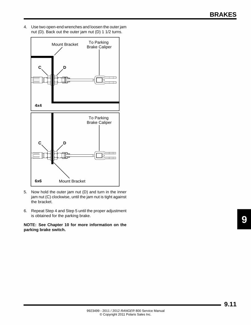
4. Use two open-end wrenches and loosen the outer jam nut (D). Back out the outer jam nut (D) 1 1/2 turns.
5. Now hold the outer jam nut (D) and turn in the inner jam nut (C) clockwise, until the jam nut is tight against the bracket.
6. Repeat Step 4 and Step 5 until the proper adjustment is obtained for the parking brake.
NOTE: See Chapter 10 for more information on the parking brake switch.
DC
Mount Bracket To Parking Brake Caliper
4x4
DC
Mount Bracket
To Parking Brake Caliper
6x6
9.119923499 - 2011 / 2012 RANGER 800 Service Manual
© Copyright 2011 Polaris Sales Inc.
BRAKES
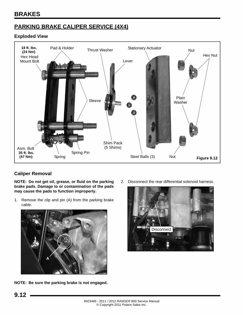
PARKING BRAKE CALIPER SERVICE (4X4)
Exploded View
Caliper Removal
NOTE: Do not get oil, grease, or fluid on the parking brake pads. Damage to or contamination of the pads may cause the pads to function improperly.
1. Remove the clip and pin (A) from the parking brake cable.
NOTE: Be sure the parking brake is not engaged.
2. Disconnect the rear differential solenoid harness.
Nut
Hex HeadMount Bolt
Sleeve
Thrust Washer
Shim Pack(5 Shims)
Pad & Holder
Lever
Asm. Bolt
Steel Balls (3)
Hex Nut
Stationary Actuator
SpringSpring Pin
Figure 9.12
18 ft. lbs.
35 ft. lbs.
(24 Nm)
(47 Nm) Nut
PlainWasher
A
Disconnect
9.129923499 - 2011 / 2012 RANGER 800 Service Manual
© Copyright 2011 Polaris Sales Inc.
BRAKES
9
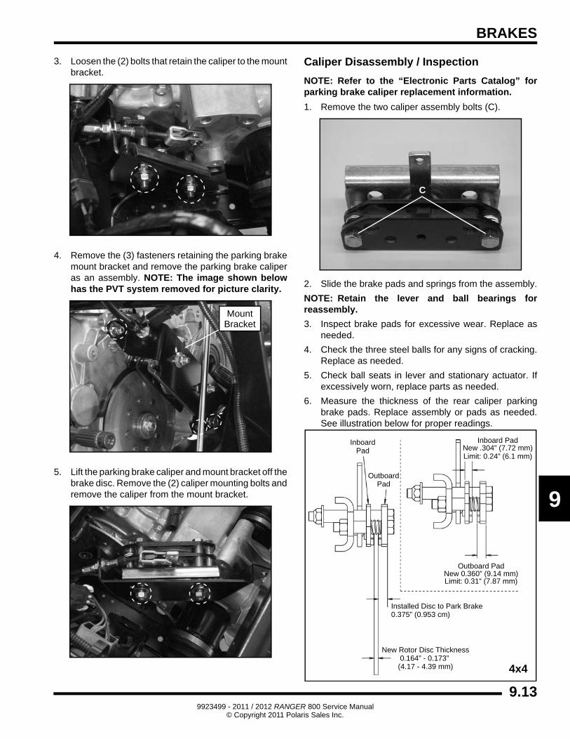
3. Loosen the (2) bolts that retain the caliper to the mount bracket.
4. Remove the (3) fasteners retaining the parking brake mount bracket and remove the parking brake caliper as an assembly. NOTE: The image shown below has the PVT system removed for picture clarity.
5. Lift the parking brake caliper and mount bracket off the brake disc. Remove the (2) caliper mounting bolts and remove the caliper from the mount bracket.
Caliper Disassembly / Inspection
NOTE: Refer to the “Electronic Parts Catalog” for parking brake caliper replacement information.
1. Remove the two caliper assembly bolts (C).
2. Slide the brake pads and springs from the assembly.
NOTE: Retain the lever and ball bearings for reassembly.
3. Inspect brake pads for excessive wear. Replace as needed.
4. Check the three steel balls for any signs of cracking. Replace as needed.
5. Check ball seats in lever and stationary actuator. If excessively worn, replace parts as needed.
6. Measure the thickness of the rear caliper parking brake pads. Replace assembly or pads as needed. See illustration below for proper readings.
MountBracket
C
InboardPad
OutboardPad
Inboard PadNew .304” (7.72 mm)Limit: 0.24” (6.1 mm)
Outboard PadNew 0.360” (9.14 mm)Limit: 0.31” (7.87 mm)
Installed Disc to Park Brake0.375” (0.953 cm)
New Rotor Disc Thickness0.164” - 0.173”
(4.17 - 4.39 mm) 4x4
9.139923499 - 2011 / 2012 RANGER 800 Service Manual
© Copyright 2011 Polaris Sales Inc.
BRAKES
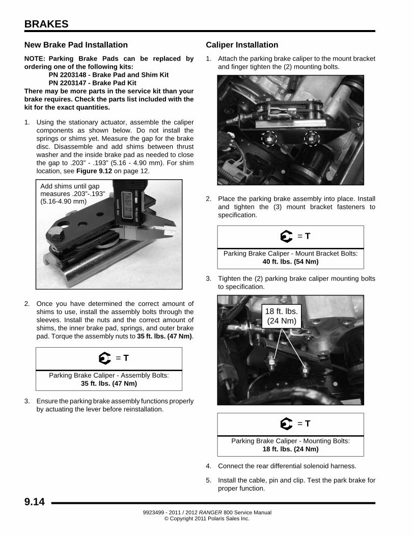
New Brake Pad Installation
NOTE: Parking Brake Pads can be replaced by ordering one of the following kits:
PN 2203148 - Brake Pad and Shim KitPN 2203147 - Brake Pad Kit
There may be more parts in the service kit than your brake requires. Check the parts list included with the kit for the exact quantities.
1. Using the stationary actuator, assemble the caliper components as shown below. Do not install the springs or shims yet. Measure the gap for the brake disc. Disassemble and add shims between thrust washer and the inside brake pad as needed to close the gap to .203” - .193” (5.16 - 4.90 mm). For shim location, see Figure 9.12 on page 12.
2. Once you have determined the correct amount of shims to use, install the assembly bolts through the sleeves. Install the nuts and the correct amount of shims, the inner brake pad, springs, and outer brake pad. Torque the assembly nuts to 35 ft. lbs. (47 Nm).
3. Ensure the parking brake assembly functions properly by actuating the lever before reinstallation.
Caliper Installation
1. Attach the parking brake caliper to the mount bracket and finger tighten the (2) mounting bolts.
2. Place the parking brake assembly into place. Install and tighten the (3) mount bracket fasteners to specification.
3. Tighten the (2) parking brake caliper mounting bolts to specification.
4. Connect the rear differential solenoid harness.
5. Install the cable, pin and clip. Test the park brake for proper function.
= T
Parking Brake Caliper - Assembly Bolts: 35 ft. lbs. (47 Nm)
Add shims until gapmeasures .203”-.193”(5.16-4.90 mm)
= T
Parking Brake Caliper - Mount Bracket Bolts: 40 ft. lbs. (54 Nm)
= T
Parking Brake Caliper - Mounting Bolts: 18 ft. lbs. (24 Nm)
18 ft. lbs.(24 Nm)
9.149923499 - 2011 / 2012 RANGER 800 Service Manual
© Copyright 2011 Polaris Sales Inc.
BRAKES
9
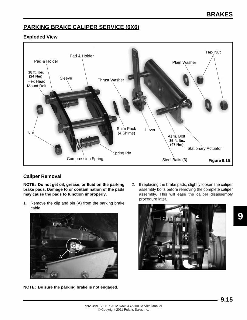
PARKING BRAKE CALIPER SERVICE (6X6)
Exploded View
Caliper Removal
NOTE: Do not get oil, grease, or fluid on the parking brake pads. Damage to or contamination of the pads may cause the pads to function improperly.
1. Remove the clip and pin (A) from the parking brake cable.
NOTE: Be sure the parking brake is not engaged.
2. If replacing the brake pads, slightly loosen the caliper assembly bolts before removing the complete caliper assembly. This will ease the caliper disassembly procedure later.
Pad & Holder
Nut
Hex HeadMount Bolt
Sleeve Thrust Washer
Shim Pack(4 Shims)
Pad & Holder
Lever
Asm. Bolt
Steel Balls (3)
Plain Washer
Hex Nut
Stationary Actuator
Compression Spring
Spring Pin
Figure 9.15
18 ft. lbs.
35 ft. lbs.
(24 Nm)
(47 Nm)
A
9.159923499 - 2011 / 2012 RANGER 800 Service Manual
© Copyright 2011 Polaris Sales Inc.
BRAKES
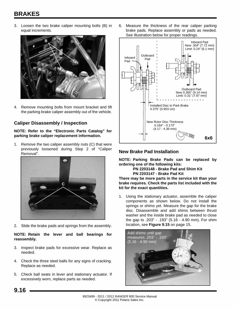
3. Loosen the two brake caliper mounting bolts (B) in equal increments.
4. Remove mounting bolts from mount bracket and lift the parking brake caliper assembly out of the vehicle.
Caliper Disassembly / Inspection
NOTE: Refer to the “Electronic Parts Catalog” for parking brake caliper replacement information.
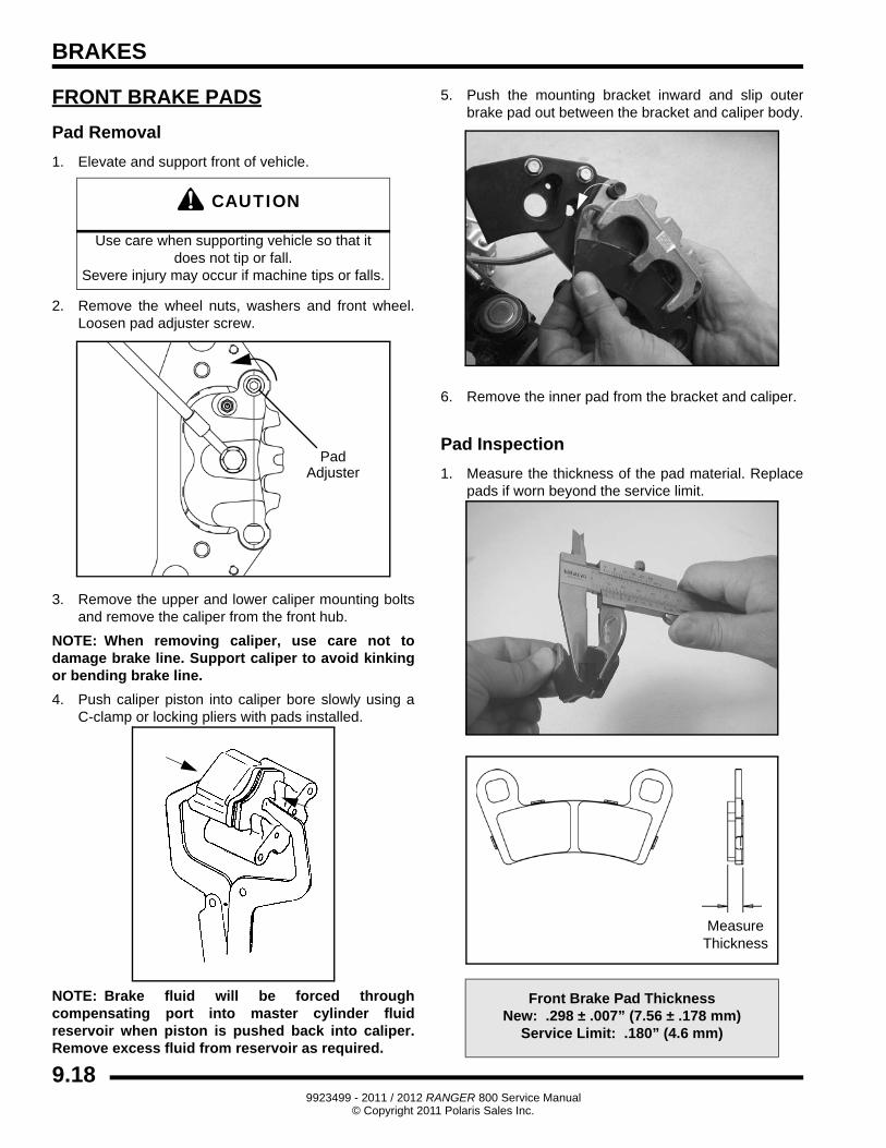
1. Remove the two caliper assembly nuts (C) that were previously loosened during Step 2 of “Caliper Removal”.
2. Slide the brake pads and springs from the assembly.
NOTE: Retain the lever and ball bearings for reassembly.
3. Inspect brake pads for excessive wear. Replace as needed.
4. Check the three steel balls for any signs of cracking. Replace as needed.
5. Check ball seats in lever and stationary actuator. If excessively worn, replace parts as needed.
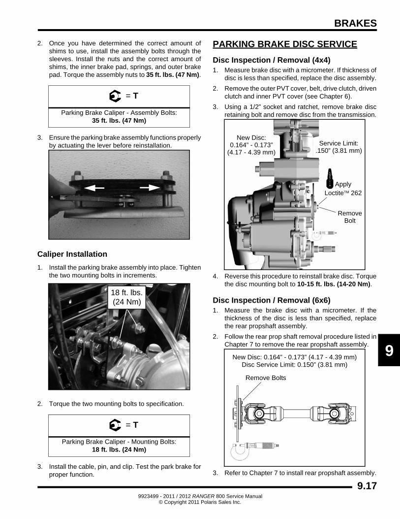
6. Measure the thickness of the rear caliper parking brake pads. Replace assembly or pads as needed. See illustration below for proper readings.
New Brake Pad Installation
NOTE: Parking Brake Pads can be replaced by ordering one of the following kits:
PN 2203148 - Brake Pad and Shim KitPN 2203147 - Brake Pad Kit
There may be more parts in the service kit than your brake requires. Check the parts list included with the kit for the exact quantities.
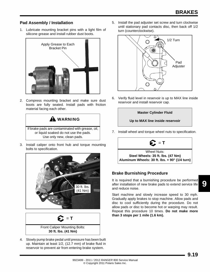
1. Using the stationary actuator, assemble the caliper components as shown below. Do not install the springs or shims yet. Measure the gap for the brake disc. Disassemble and add shims between thrust washer and the inside brake pad as needed to close the gap to .203” - .193” (5.16 - 4.90 mm). For shim location, see Figure 9.15 on page 15.
B
C
InboardPad
OutboardPad
Inboard PadNew .304” (7.72 mm)Limit: 0.24” (6.1 mm)
Outboard PadNew 0.360” (9.14 mm)Limit: 0.31” (7.87 mm)
Installed Disc to Park Brake0.375” (0.953 cm)
New Rotor Disc Thickness0.164” - 0.173”
(4.17 - 4.39 mm)
6x6
Add shims until gapmeasures .203” - .193”(5.16 - 4.90 mm)
9.169923499 - 2011 / 2012 RANGER 800 Service Manual
© Copyright 2011 Polaris Sales Inc.
BRAKES
9
2. Once you have determined the correct amount of shims to use, install the assembly bolts through the sleeves. Install the nuts and the correct amount of shims, the inner brake pad, springs, and outer brake pad. Torque the assembly nuts to 35 ft. lbs. (47 Nm).
3. Ensure the parking brake assembly functions properly by actuating the lever before reinstallation.
Caliper Installation
1. Install the parking brake assembly into place. Tighten the two mounting bolts in increments.
2. Torque the two mounting bolts to specification.
3. Install the cable, pin, and clip. Test the park brake for proper function.
PARKING BRAKE DISC SERVICE
Disc Inspection / Removal (4x4)1. Measure brake disc with a micrometer. If thickness of
disc is less than specified, replace the disc assembly.
2. Remove the outer PVT cover, belt, drive clutch, driven clutch and inner PVT cover (see Chapter 6).
3. Using a 1/2” socket and ratchet, remove brake disc retaining bolt and remove disc from the transmission.
4. Reverse this procedure to reinstall brake disc. Torque the disc mounting bolt to 10-15 ft. lbs. (14-20 Nm).
Disc Inspection / Removal (6x6)1. Measure the brake disc with a micrometer. If the
thickness of the disc is less than specified, replace the rear propshaft assembly.
2. Follow the rear prop shaft removal procedure listed in Chapter 7 to remove the rear propshaft assembly.
3. Refer to Chapter 7 to install rear propshaft assembly.
= T
Parking Brake Caliper - Assembly Bolts: 35 ft. lbs. (47 Nm)
= T
Parking Brake Caliper - Mounting Bolts: 18 ft. lbs. (24 Nm)
18 ft. lbs.(24 Nm)
Remove
Service Limit:New Disc:
Bolt
.150” (3.81 mm)0.164” - 0.173”
(4.17 - 4.39 mm)
ApplyLoctiteTM 262
Remove Bolts
Disc Service Limit: 0.150” (3.81 mm)New Disc: 0.164” - 0.173” (4.17 - 4.39 mm)
9.179923499 - 2011 / 2012 RANGER 800 Service Manual
© Copyright 2011 Polaris Sales Inc.
BRAKES
FRONT BRAKE PADS
Pad Removal
1. Elevate and support front of vehicle.
2. Remove the wheel nuts, washers and front wheel. Loosen pad adjuster screw.
3. Remove the upper and lower caliper mounting bolts and remove the caliper from the front hub.
NOTE: When removing caliper, use care not to damage brake line. Support caliper to avoid kinking or bending brake line.
4. Push caliper piston into caliper bore slowly using a C-clamp or locking pliers with pads installed.
NOTE: Brake fluid will be forced through compensating port into master cylinder fluid reservoir when piston is pushed back into caliper. Remove excess fluid from reservoir as required.
5. Push the mounting bracket inward and slip outer brake pad out between the bracket and caliper body.
6. Remove the inner pad from the bracket and caliper.
Pad Inspection
1. Measure the thickness of the pad material. Replace pads if worn beyond the service limit.
CAUTION
Use care when supporting vehicle so that it does not tip or fall.
Severe injury may occur if machine tips or falls.
PadAdjuster
Front Brake Pad ThicknessNew: .298 ± .007” (7.56 ± .178 mm)
Service Limit: .180” (4.6 mm)
MeasureThickness
9.189923499 - 2011 / 2012 RANGER 800 Service Manual
© Copyright 2011 Polaris Sales Inc.
BRAKES
9
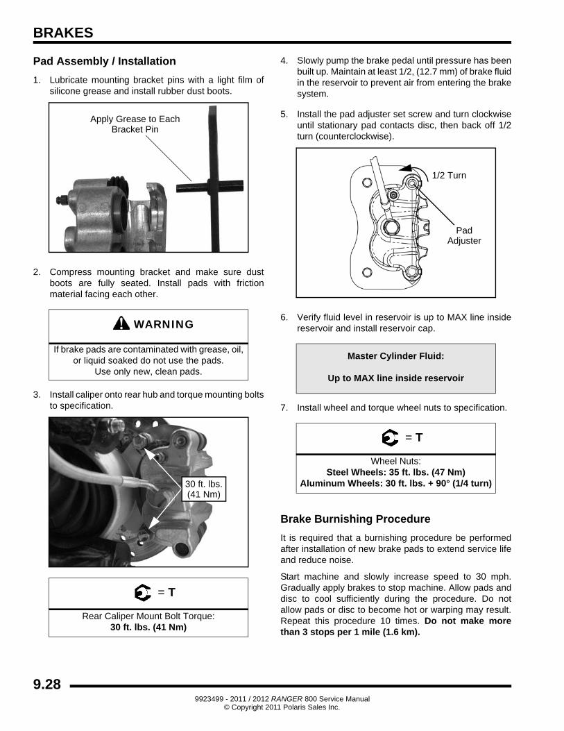
Pad Assembly / Installation
1. Lubricate mounting bracket pins with a light film of silicone grease and install rubber dust boots.
2. Compress mounting bracket and make sure dust boots are fully seated. Install pads with friction material facing each other.
3. Install caliper onto front hub and torque mounting bolts to specification.
4. Slowly pump brake pedal until pressure has been built up. Maintain at least 1/2, (12.7 mm) of brake fluid in reservoir to prevent air from entering brake system.
5. Install the pad adjuster set screw and turn clockwise until stationary pad contacts disc, then back off 1/2 turn (counterclockwise).
6. Verify fluid level in reservoir is up to MAX line inside reservoir and install reservoir cap.
7. Install wheel and torque wheel nuts to specification.
Brake Burnishing Procedure
It is required that a burnishing procedure be performed after installation of new brake pads to extend service life and reduce noise.
Start machine and slowly increase speed to 30 mph. Gradually apply brakes to stop machine. Allow pads and disc to cool sufficiently during the procedure. Do not allow pads or disc to become hot or warping may result. Repeat this procedure 10 times. Do not make more than 3 stops per 1 mile (1.6 km).
WARNING
If brake pads are contaminated with grease, oil, or liquid soaked do not use the pads.
Use only new, clean pads.
= T
Front Caliper Mounting Bolts:30 ft. lbs. (41 Nm)
Apply Grease to EachBracket Pin
30 ft. lbs.(41 Nm)
Master Cylinder Fluid
Up to MAX line inside reservoir
= T
Wheel Nuts:Steel Wheels: 35 ft. lbs. (47 Nm)
Aluminum Wheels: 30 ft. lbs. + 90° (1/4 turn)
PadAdjuster
1/2 Turn
9.199923499 - 2011 / 2012 RANGER 800 Service Manual
© Copyright 2011 Polaris Sales Inc.
BRAKES
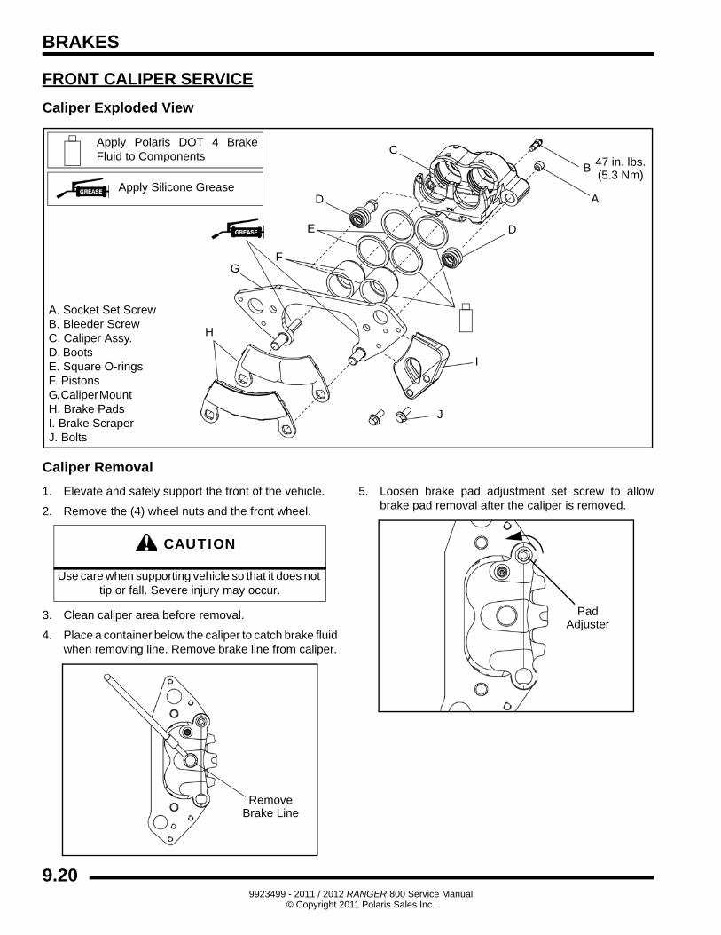
FRONT CALIPER SERVICE
Caliper Exploded View
Caliper Removal
1. Elevate and safely support the front of the vehicle.
2. Remove the (4) wheel nuts and the front wheel.
3. Clean caliper area before removal.
4. Place a container below the caliper to catch brake fluid when removing line. Remove brake line from caliper.
5. Loosen brake pad adjustment set screw to allow brake pad removal after the caliper is removed.
A. Socket Set Screw B. Bleeder Screw C. Caliper Assy. D. Boots E. Square O-ringsF. Pistons G. Caliper Mount H. Brake PadsI. Brake ScraperJ. Bolts
A
B
C
D
FG
H
Apply Silicone Grease
Apply Polaris DOT 4 Brake Fluid to Components 47 in. lbs.
(5.3 Nm)
D
I
E
J
CAUTION
Use care when supporting vehicle so that it does not tip or fall. Severe injury may occur.
RemoveBrake Line
PadAdjuster
9.209923499 - 2011 / 2012 RANGER 800 Service Manual
© Copyright 2011 Polaris Sales Inc.
BRAKES
9
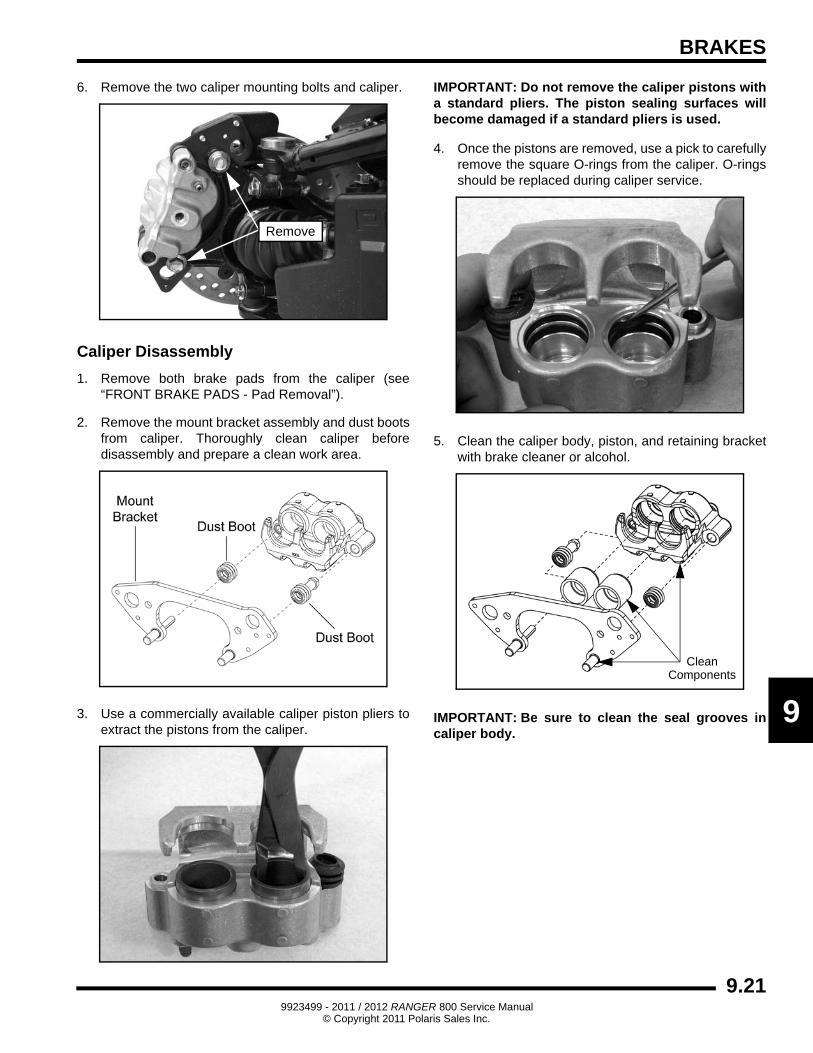
6. Remove the two caliper mounting bolts and caliper.
Caliper Disassembly
1. Remove both brake pads from the caliper (see “FRONT BRAKE PADS - Pad Removal”).
2. Remove the mount bracket assembly and dust boots from caliper. Thoroughly clean caliper before disassembly and prepare a clean work area.
3. Use a commercially available caliper piston pliers to extract the pistons from the caliper.
IMPORTANT: Do not remove the caliper pistons with a standard pliers. The piston sealing surfaces will become damaged if a standard pliers is used.
4. Once the pistons are removed, use a pick to carefully remove the square O-rings from the caliper. O-rings should be replaced during caliper service.
5. Clean the caliper body, piston, and retaining bracket with brake cleaner or alcohol.
IMPORTANT: Be sure to clean the seal grooves in caliper body.
Remove
CleanComponents
9.219923499 - 2011 / 2012 RANGER 800 Service Manual
© Copyright 2011 Polaris Sales Inc.
BRAKES
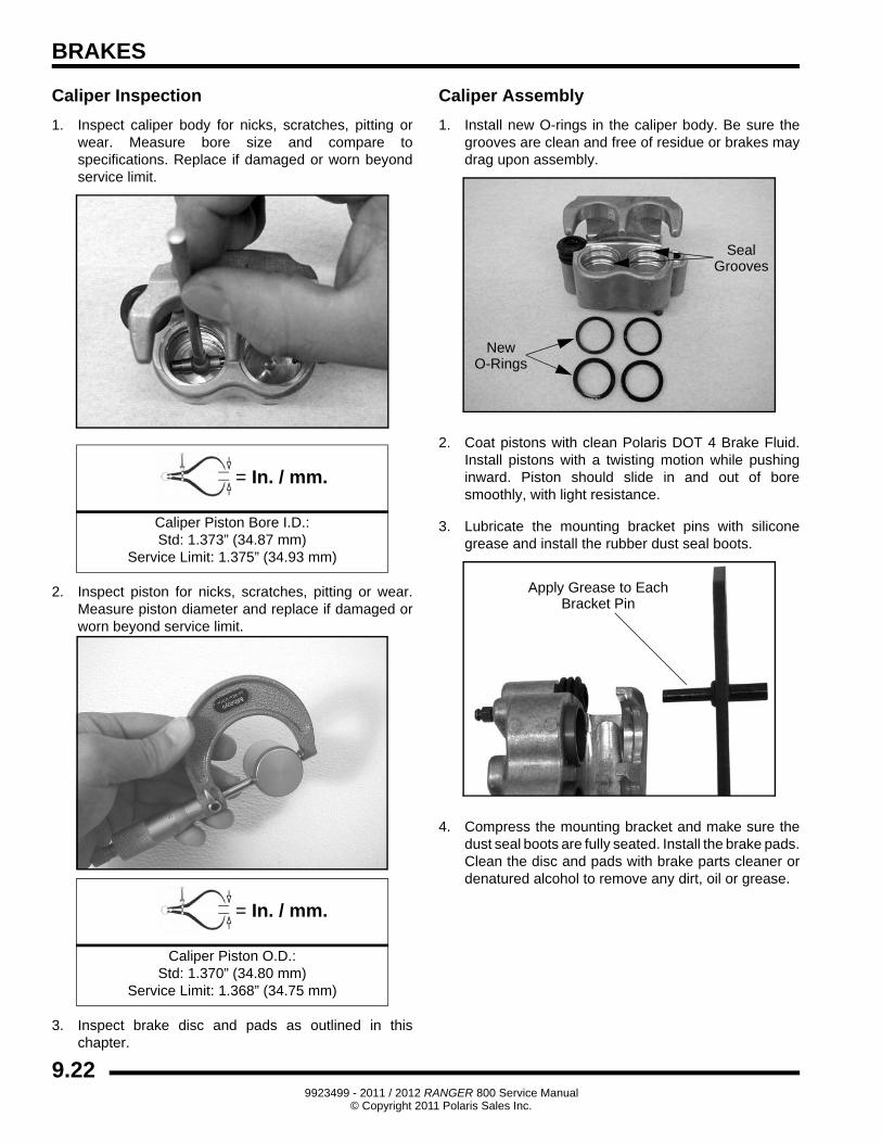
Caliper Inspection
1. Inspect caliper body for nicks, scratches, pitting or wear. Measure bore size and compare to specifications. Replace if damaged or worn beyond service limit.
2. Inspect piston for nicks, scratches, pitting or wear. Measure piston diameter and replace if damaged or worn beyond service limit.
3. Inspect brake disc and pads as outlined in this chapter.
Caliper Assembly
1. Install new O-rings in the caliper body. Be sure the grooves are clean and free of residue or brakes may drag upon assembly.
2. Coat pistons with clean Polaris DOT 4 Brake Fluid. Install pistons with a twisting motion while pushing inward. Piston should slide in and out of bore smoothly, with light resistance.
3. Lubricate the mounting bracket pins with silicone grease and install the rubber dust seal boots.
4. Compress the mounting bracket and make sure the dust seal boots are fully seated. Install the brake pads. Clean the disc and pads with brake parts cleaner or denatured alcohol to remove any dirt, oil or grease.
= In. / mm.
Caliper Piston Bore I.D.:Std: 1.373” (34.87 mm)
Service Limit: 1.375” (34.93 mm)
= In. / mm.
Caliper Piston O.D.:Std: 1.370” (34.80 mm)
Service Limit: 1.368” (34.75 mm)
New
SealGrooves
O-Rings
Apply Grease to EachBracket Pin
9.229923499 - 2011 / 2012 RANGER 800 Service Manual
© Copyright 2011 Polaris Sales Inc.
BRAKES
9
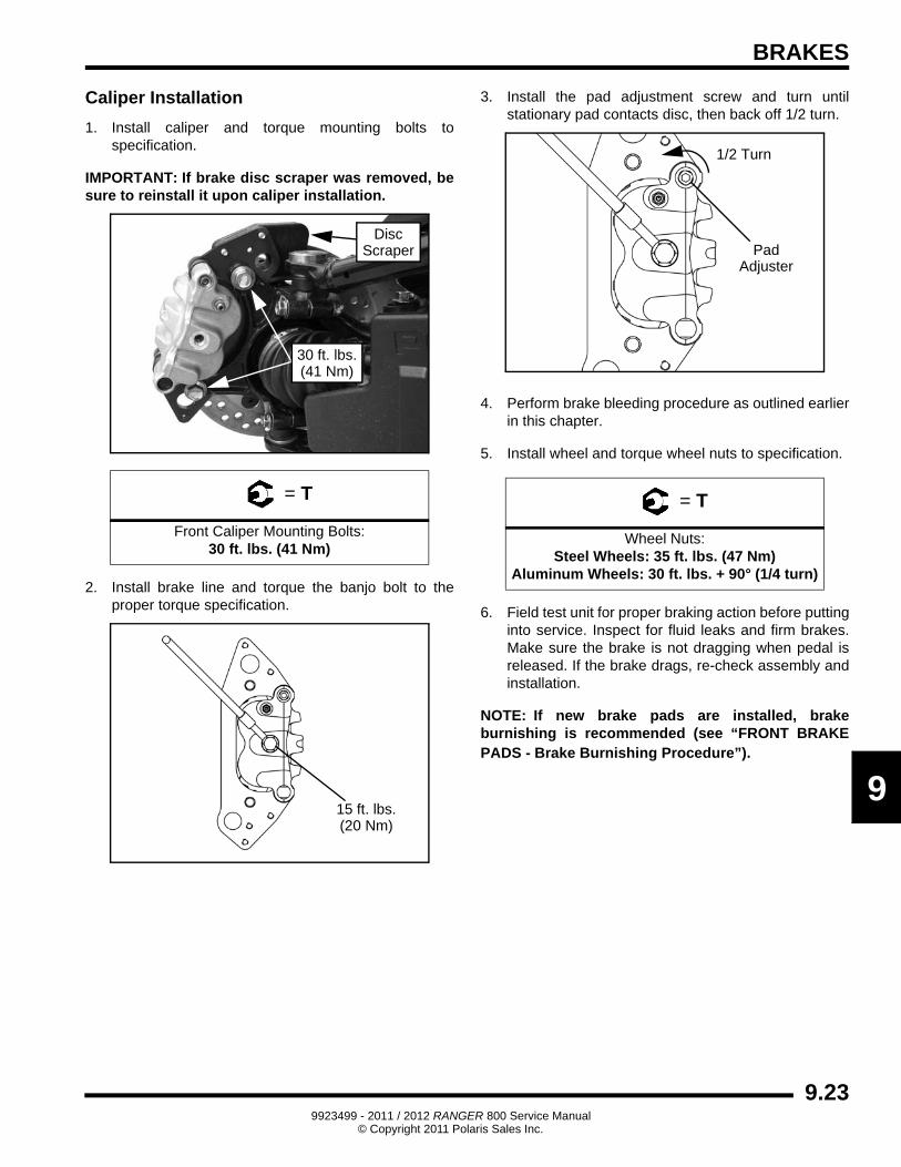
Caliper Installation
1. Install caliper and torque mounting bolts to specification.
IMPORTANT: If brake disc scraper was removed, be sure to reinstall it upon caliper installation.
2. Install brake line and torque the banjo bolt to the proper torque specification.
3. Install the pad adjustment screw and turn until stationary pad contacts disc, then back off 1/2 turn.
4. Perform brake bleeding procedure as outlined earlier in this chapter.
5. Install wheel and torque wheel nuts to specification.
6. Field test unit for proper braking action before putting into service. Inspect for fluid leaks and firm brakes. Make sure the brake is not dragging when pedal is released. If the brake drags, re-check assembly and installation.
NOTE: If new brake pads are installed, brake burnishing is recommended (see “FRONT BRAKE PADS - Brake Burnishing Procedure”).
= T
Front Caliper Mounting Bolts:30 ft. lbs. (41 Nm)
30 ft. lbs.(41 Nm)
DiscScraper
15 ft. lbs.(20 Nm)
= T
Wheel Nuts:Steel Wheels: 35 ft. lbs. (47 Nm)
Aluminum Wheels: 30 ft. lbs. + 90° (1/4 turn)
PadAdjuster
1/2 Turn
9.239923499 - 2011 / 2012 RANGER 800 Service Manual
© Copyright 2011 Polaris Sales Inc.
BRAKES
FRONT BRAKE DISC
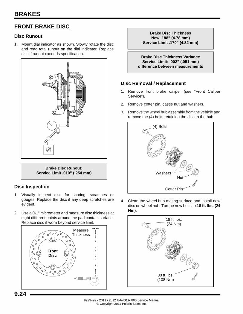
Disc Runout
1. Mount dial indicator as shown. Slowly rotate the disc and read total runout on the dial indicator. Replace disc if runout exceeds specification.
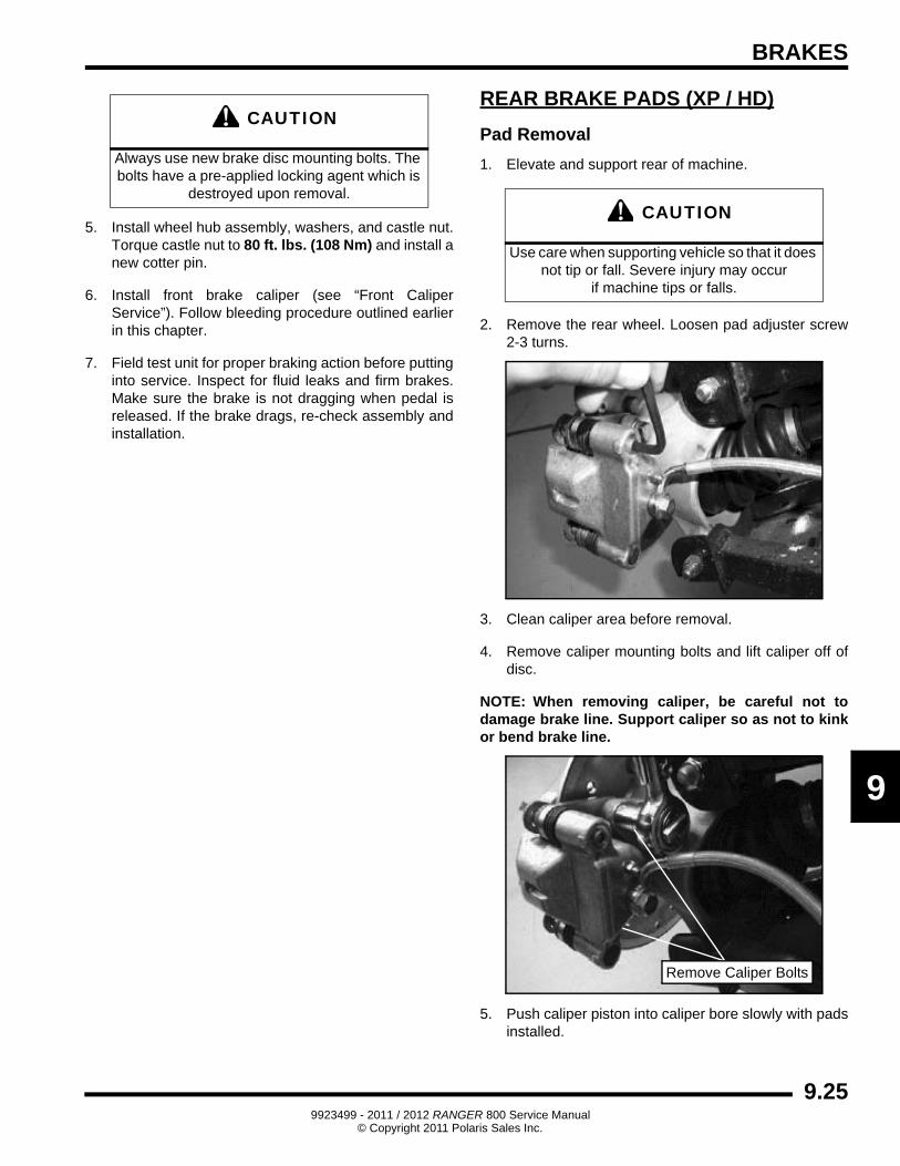
Disc Inspection
1. Visually inspect disc for scoring, scratches or gouges. Replace the disc if any deep scratches are evident.
2. Use a 0-1” micrometer and measure disc thickness at eight different points around the pad contact surface. Replace disc if worn beyond service limit.
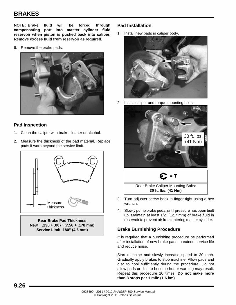
Disc Removal / Replacement
1. Remove front brake caliper (see “Front Caliper Service”).
2. Remove cotter pin, castle nut and washers.
3. Remove the wheel hub assembly from the vehicle and remove the (4) bolts retaining the disc to the hub.
4. Clean the wheel hub mating surface and install new disc on wheel hub. Torque new bolts to 18 ft. lbs. (24 Nm).
Brake Disc Runout:Service Limit .010” (.254 mm)
MeasureThickness
FrontDisc
Brake Disc ThicknessNew .188” (4.78 mm)
Service Limit .170” (4.32 mm)
Brake Disc Thickness VarianceService Limit: .002” (.051 mm)
difference between measurements
Cotter Pin
WashersNut
(4) Bolts
18 ft. lbs.(24 Nm)
80 ft. lbs.(108 Nm)
9.249923499 - 2011 / 2012 RANGER 800 Service Manual
© Copyright 2011 Polaris Sales Inc.
BRAKES
9
5. Install wheel hub assembly, washers, and castle nut. Torque castle nut to 80 ft. lbs. (108 Nm) and install a new cotter pin.
6. Install front brake caliper (see “Front Caliper Service”). Follow bleeding procedure outlined earlier in this chapter.
7. Field test unit for proper braking action before putting into service. Inspect for fluid leaks and firm brakes. Make sure the brake is not dragging when pedal is released. If the brake drags, re-check assembly and installation.
REAR BRAKE PADS (XP / HD)
Pad Removal
1. Elevate and support rear of machine.
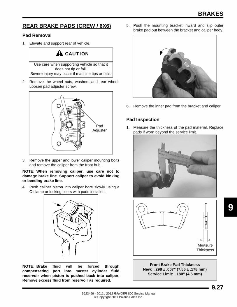
2. Remove the rear wheel. Loosen pad adjuster screw 2-3 turns.
3. Clean caliper area before removal.
4. Remove caliper mounting bolts and lift caliper off of disc.
NOTE: When removing caliper, be careful not to damage brake line. Support caliper so as not to kink or bend brake line.
5. Push caliper piston into caliper bore slowly with pads installed.
CAUTION
Always use new brake disc mounting bolts. The bolts have a pre-applied locking agent which is
destroyed upon removal.CAUTION
Use care when supporting vehicle so that it does not tip or fall. Severe injury may occur
if machine tips or falls.
Remove Caliper Bolts
9.259923499 - 2011 / 2012 RANGER 800 Service Manual
© Copyright 2011 Polaris Sales Inc.
BRAKES
NOTE: Brake fluid will be forced through compensating port into master cylinder fluid reservoir when piston is pushed back into caliper. Remove excess fluid from reservoir as required.
6. Remove the brake pads.
Pad Inspection
1. Clean the caliper with brake cleaner or alcohol.
2. Measure the thickness of the pad material. Replace pads if worn beyond the service limit.
Pad Installation
1. Install new pads in caliper body.
2. Install caliper and torque mounting bolts.
3. Turn adjuster screw back in finger tight using a hex wrench.
4. Slowly pump brake pedal until pressure has been built up. Maintain at least 1/2" (12.7 mm) of brake fluid in reservoir to prevent air from entering master cylinder.
Brake Burnishing Procedure
It is required that a burnishing procedure be performed after installation of new brake pads to extend service life and reduce noise.
Start machine and slowly increase speed to 30 mph. Gradually apply brakes to stop machine. Allow pads and disc to cool sufficiently during the procedure. Do not allow pads or disc to become hot or warping may result. Repeat this procedure 10 times. Do not make more than 3 stops per 1 mile (1.6 km).
Rear Brake Pad ThicknessNew .298 + .007” (7.56 + .178 mm)
Service Limit .180” (4.6 mm)
MeasureThickness
= T
Rear Brake Caliper Mounting Bolts:30 ft. lbs. (41 Nm)
30 ft. lbs.(41 Nm)
9.269923499 - 2011 / 2012 RANGER 800 Service Manual
© Copyright 2011 Polaris Sales Inc.
BRAKES
9
REAR BRAKE PADS (CREW / 6X6)
Pad Removal
1. Elevate and support rear of vehicle.
2. Remove the wheel nuts, washers and rear wheel. Loosen pad adjuster screw.
3. Remove the upper and lower caliper mounting bolts and remove the caliper from the front hub.
NOTE: When removing caliper, use care not to damage brake line. Support caliper to avoid kinking or bending brake line.
4. Push caliper piston into caliper bore slowly using a C-clamp or locking pliers with pads installed.
NOTE: Brake fluid will be forced through compensating port into master cylinder fluid reservoir when piston is pushed back into caliper. Remove excess fluid from reservoir as required.
5. Push the mounting bracket inward and slip outer brake pad out between the bracket and caliper body.
6. Remove the inner pad from the bracket and caliper.
Pad Inspection
1. Measure the thickness of the pad material. Replace pads if worn beyond the service limit.
CAUTION
Use care when supporting vehicle so that it does not tip or fall.
Severe injury may occur if machine tips or falls.
PadAdjuster
Front Brake Pad ThicknessNew: .298 ± .007” (7.56 ± .178 mm)
Service Limit: .180” (4.6 mm)
MeasureThickness
9.279923499 - 2011 / 2012 RANGER 800 Service Manual
© Copyright 2011 Polaris Sales Inc.
BRAKES
Pad Assembly / Installation
1. Lubricate mounting bracket pins with a light film of silicone grease and install rubber dust boots.
2. Compress mounting bracket and make sure dust boots are fully seated. Install pads with friction material facing each other.
3. Install caliper onto rear hub and torque mounting bolts to specification.
4. Slowly pump the brake pedal until pressure has been built up. Maintain at least 1/2, (12.7 mm) of brake fluid in the reservoir to prevent air from entering the brake system.
5. Install the pad adjuster set screw and turn clockwise until stationary pad contacts disc, then back off 1/2 turn (counterclockwise).
6. Verify fluid level in reservoir is up to MAX line inside reservoir and install reservoir cap.
7. Install wheel and torque wheel nuts to specification.
Brake Burnishing Procedure
It is required that a burnishing procedure be performed after installation of new brake pads to extend service life and reduce noise.
Start machine and slowly increase speed to 30 mph. Gradually apply brakes to stop machine. Allow pads and disc to cool sufficiently during the procedure. Do not allow pads or disc to become hot or warping may result. Repeat this procedure 10 times. Do not make more than 3 stops per 1 mile (1.6 km).
WARNING
If brake pads are contaminated with grease, oil, or liquid soaked do not use the pads.
Use only new, clean pads.
= T
Rear Caliper Mount Bolt Torque:30 ft. lbs. (41 Nm)
Apply Grease to EachBracket Pin
30 ft. lbs.(41 Nm)
Master Cylinder Fluid:
Up to MAX line inside reservoir
= T
Wheel Nuts:Steel Wheels: 35 ft. lbs. (47 Nm)
Aluminum Wheels: 30 ft. lbs. + 90° (1/4 turn)
PadAdjuster
1/2 Turn
9.289923499 - 2011 / 2012 RANGER 800 Service Manual
© Copyright 2011 Polaris Sales Inc.
BRAKES
9
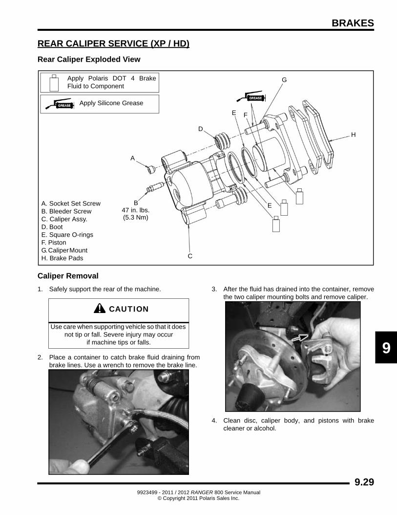
REAR CALIPER SERVICE (XP / HD)
Rear Caliper Exploded View
Caliper Removal
1. Safely support the rear of the machine.
2. Place a container to catch brake fluid draining from brake lines. Use a wrench to remove the brake line.
3. After the fluid has drained into the container, remove the two caliper mounting bolts and remove caliper.
4. Clean disc, caliper body, and pistons with brake cleaner or alcohol.
A. Socket Set Screw B. Bleeder Screw C. Caliper Assy. D. Boot E. Square O-ringsF. Piston G. Caliper Mount H. Brake Pads
A
B
C
D
E
F
G
H
Apply Silicone Grease
Apply Polaris DOT 4 Brake Fluid to Component
47 in. lbs.(5.3 Nm)
E
CAUTION
Use care when supporting vehicle so that it does not tip or fall. Severe injury may occur
if machine tips or falls.
9.299923499 - 2011 / 2012 RANGER 800 Service Manual
© Copyright 2011 Polaris Sales Inc.
BRAKES
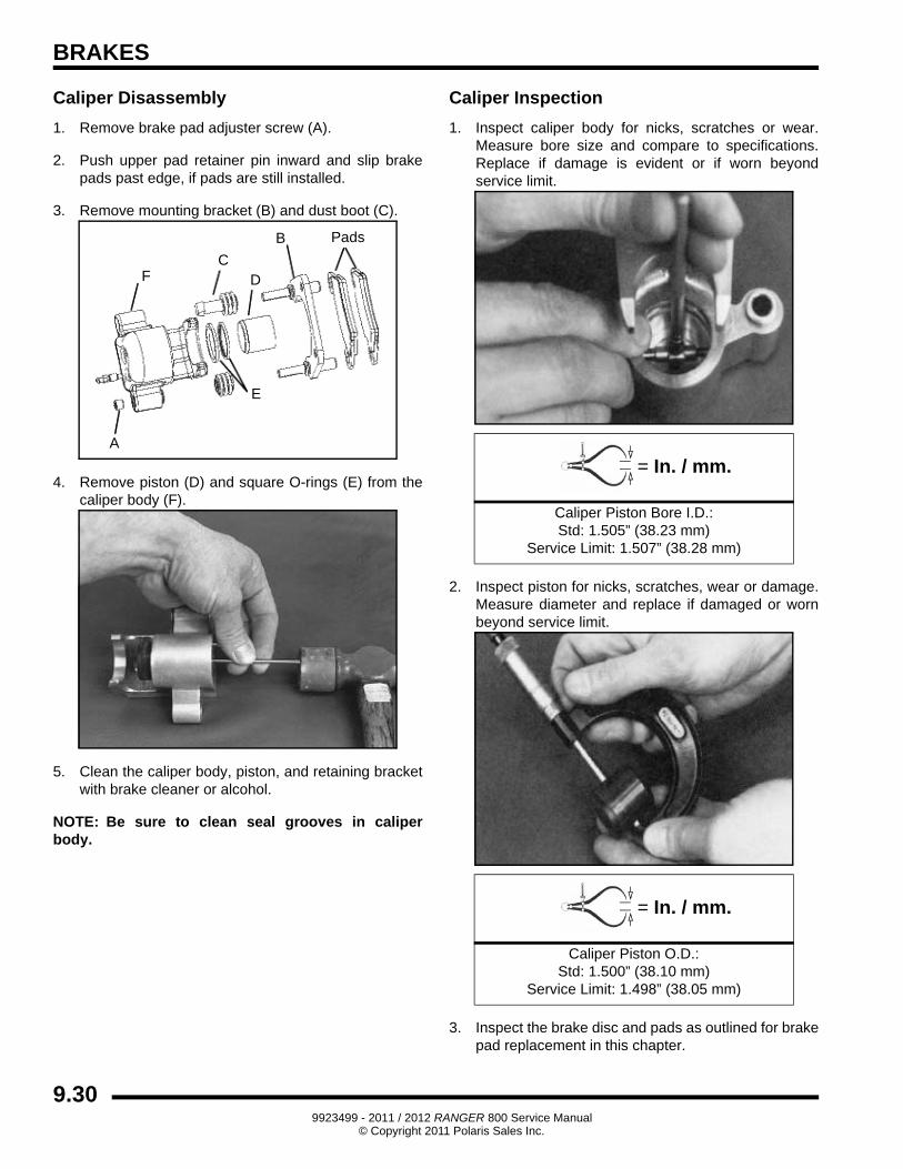
Caliper Disassembly
1. Remove brake pad adjuster screw (A).
2. Push upper pad retainer pin inward and slip brake pads past edge, if pads are still installed.
3. Remove mounting bracket (B) and dust boot (C).
4. Remove piston (D) and square O-rings (E) from the caliper body (F).
5. Clean the caliper body, piston, and retaining bracket with brake cleaner or alcohol.
NOTE: Be sure to clean seal grooves in caliper body.
Caliper Inspection
1. Inspect caliper body for nicks, scratches or wear. Measure bore size and compare to specifications. Replace if damage is evident or if worn beyond service limit.
2. Inspect piston for nicks, scratches, wear or damage. Measure diameter and replace if damaged or worn beyond service limit.
3. Inspect the brake disc and pads as outlined for brake pad replacement in this chapter.
Pads
A
B
CD
E
F
= In. / mm.
Caliper Piston Bore I.D.:Std: 1.505” (38.23 mm)
Service Limit: 1.507” (38.28 mm)
= In. / mm.
Caliper Piston O.D.:Std: 1.500” (38.10 mm)
Service Limit: 1.498” (38.05 mm)
9.309923499 - 2011 / 2012 RANGER 800 Service Manual
© Copyright 2011 Polaris Sales Inc.
BRAKES
9
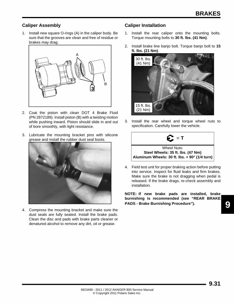
Caliper Assembly
1. Install new square O-rings (A) in the caliper body. Be sure that the grooves are clean and free of residue or brakes may drag.
2. Coat the piston with clean DOT 4 Brake Fluid (PN 2872189). Install piston (B) with a twisting motion while pushing inward. Piston should slide in and out of bore smoothly, with light resistance.
3. Lubricate the mounting bracket pins with silicone grease and install the rubber dust seal boots.
4. Compress the mounting bracket and make sure the dust seals are fully seated. Install the brake pads. Clean the disc and pads with brake parts cleaner or denatured alcohol to remove any dirt, oil or grease.
Caliper Installation
1. Install the rear caliper onto the mounting bolts. Torque mounting bolts to 30 ft. lbs. (41 Nm).
2. Install brake line banjo bolt. Torque banjo bolt to 15 ft. lbs. (21 Nm).
3. Install the rear wheel and torque wheel nuts to specification. Carefully lower the vehicle.
4. Field test unit for proper braking action before putting into service. Inspect for fluid leaks and firm brakes. Make sure the brake is not dragging when pedal is released. If the brake drags, re-check assembly and installation.
NOTE: If new brake pads are installed, brake burnishing is recommended (see “REAR BRAKE PADS - Brake Burnishing Procedure”).
A
B
= T
Wheel Nuts:Steel Wheels: 35 ft. lbs. (47 Nm)
Aluminum Wheels: 30 ft. lbs. + 90° (1/4 turn)
30 ft. lbs.(41 Nm)
15 ft. lbs.(21 Nm)
9.319923499 - 2011 / 2012 RANGER 800 Service Manual
© Copyright 2011 Polaris Sales Inc.
BRAKES
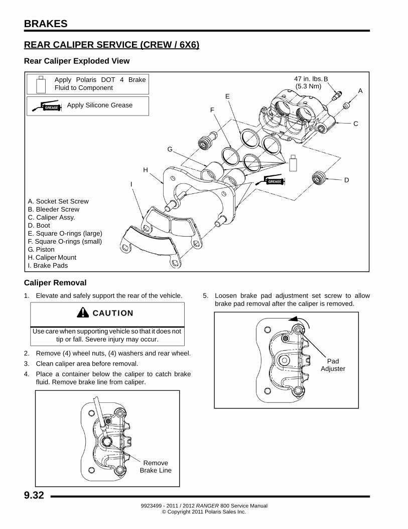
REAR CALIPER SERVICE (CREW / 6X6)
Rear Caliper Exploded View
Caliper Removal
1. Elevate and safely support the rear of the vehicle.
2. Remove (4) wheel nuts, (4) washers and rear wheel.
3. Clean caliper area before removal.
4. Place a container below the caliper to catch brake fluid. Remove brake line from caliper.
5. Loosen brake pad adjustment set screw to allow brake pad removal after the caliper is removed.
A. Socket Set Screw B. Bleeder Screw C. Caliper Assy. D. Boot E. Square O-rings (large)F. Square O-rings (small)G. Piston H. Caliper Mount I. Brake Pads
A
B
C
D
E
F
G
H
Apply Silicone Grease
Apply Polaris DOT 4 Brake Fluid to Component
47 in. lbs.(5.3 Nm)
I
CAUTION
Use care when supporting vehicle so that it does not tip or fall. Severe injury may occur.
RemoveBrake Line
PadAdjuster
9.329923499 - 2011 / 2012 RANGER 800 Service Manual
© Copyright 2011 Polaris Sales Inc.
BRAKES
9
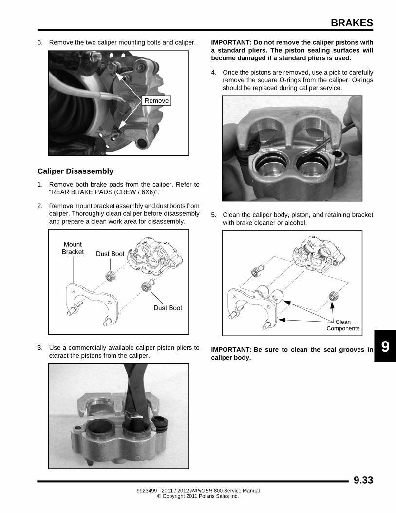
6. Remove the two caliper mounting bolts and caliper.
Caliper Disassembly
1. Remove both brake pads from the caliper. Refer to “REAR BRAKE PADS (CREW / 6X6)”.
2. Remove mount bracket assembly and dust boots from caliper. Thoroughly clean caliper before disassembly and prepare a clean work area for disassembly.
3. Use a commercially available caliper piston pliers to extract the pistons from the caliper.
IMPORTANT: Do not remove the caliper pistons with a standard pliers. The piston sealing surfaces will become damaged if a standard pliers is used.
4. Once the pistons are removed, use a pick to carefully remove the square O-rings from the caliper. O-rings should be replaced during caliper service.
5. Clean the caliper body, piston, and retaining bracket with brake cleaner or alcohol.
IMPORTANT: Be sure to clean the seal grooves in caliper body.
Remove
CleanComponents
9.339923499 - 2011 / 2012 RANGER 800 Service Manual
© Copyright 2011 Polaris Sales Inc.

BRAKES
Caliper Inspection
1. Inspect caliper body for nicks, scratches, pitting or wear. Measure bore size and compare to specifications. Replace if damaged or worn beyond service limit.
2. Inspect piston for nicks, scratches, pitting or wear. Measure piston diameter and replace if damaged or worn beyond service limit.
3. Inspect the brake disc and pads as outlined in this chapter.
Caliper Assembly
1. Install new O-rings in the caliper body. Be sure the grooves are clean and free of residue or brakes may drag upon assembly.
2. Coat pistons with clean Polaris DOT 4 Brake Fluid. Install pistons with a twisting motion while pushing inward. Piston should slide in and out of bore smoothly, with light resistance.
3. Lubricate the mounting bracket pins with silicone grease and install the rubber dust seal boots.
4. Compress the mounting bracket and make sure the dust seal boots are fully seated. Install the brake pads. Clean the disc and pads with brake parts cleaner or denatured alcohol to remove any dirt, oil or grease.
= In. / mm.
Caliper Piston Bore I.D.:Std: 1.192” (30.28 mm)
Service Limit: 1.194” (34.33 mm)
= In. / mm.
Caliper Piston O.D.:Std: 1.186” (30.12 mm)
Service Limit: 1.184” (30.07 mm)
New
SealGrooves
O-Rings
Apply Grease to EachBracket Pin
9.349923499 - 2011 / 2012 RANGER 800 Service Manual
© Copyright 2011 Polaris Sales Inc.
BRAKES
9
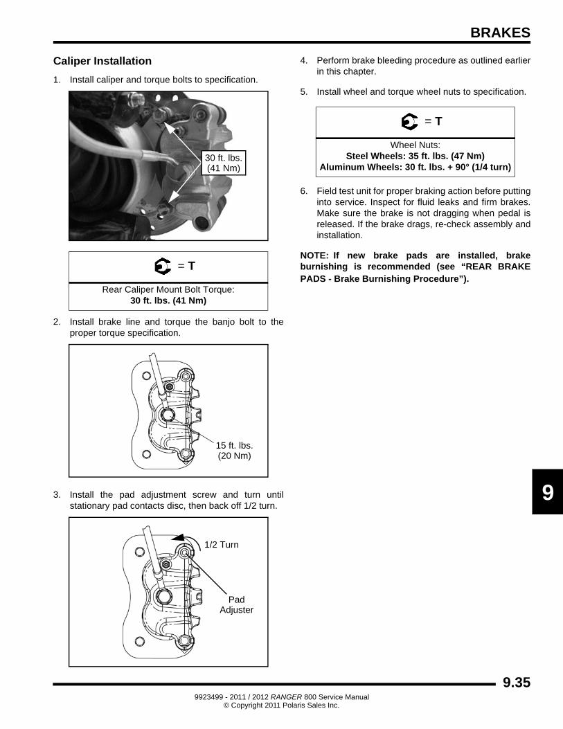
Caliper Installation
1. Install caliper and torque bolts to specification.
2. Install brake line and torque the banjo bolt to the proper torque specification.
3. Install the pad adjustment screw and turn until stationary pad contacts disc, then back off 1/2 turn.
4. Perform brake bleeding procedure as outlined earlier in this chapter.
5. Install wheel and torque wheel nuts to specification.
6. Field test unit for proper braking action before putting into service. Inspect for fluid leaks and firm brakes. Make sure the brake is not dragging when pedal is released. If the brake drags, re-check assembly and installation.
NOTE: If new brake pads are installed, brake burnishing is recommended (see “REAR BRAKE PADS - Brake Burnishing Procedure”).
= T
Rear Caliper Mount Bolt Torque:30 ft. lbs. (41 Nm)
30 ft. lbs.(41 Nm)
15 ft. lbs.(20 Nm)
PadAdjuster
1/2 Turn
= T
Wheel Nuts:Steel Wheels: 35 ft. lbs. (47 Nm)
Aluminum Wheels: 30 ft. lbs. + 90° (1/4 turn)
9.359923499 - 2011 / 2012 RANGER 800 Service Manual
© Copyright 2011 Polaris Sales Inc.
BRAKES
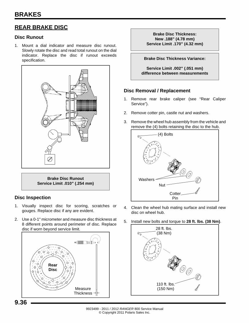
REAR BRAKE DISC
Disc Runout
1. Mount a dial indicator and measure disc runout. Slowly rotate the disc and read total runout on the dial indicator. Replace the disc if runout exceeds specification.
Disc Inspection
1. Visually inspect disc for scoring, scratches or gouges. Replace disc if any are evident.
2. Use a 0-1" micrometer and measure disc thickness at 8 different points around perimeter of disc. Replace disc if worn beyond service limit.
Disc Removal / Replacement
1. Remove rear brake caliper (see “Rear Caliper Service”).
2. Remove cotter pin, castle nut and washers.
3. Remove the wheel hub assembly from the vehicle and remove the (4) bolts retaining the disc to the hub.
4. Clean the wheel hub mating surface and install new disc on wheel hub.
5. Install new bolts and torque to 28 ft. lbs. (38 Nm).
Brake Disc RunoutService Limit .010” (.254 mm)
MeasureThickness
RearDisc
Brake Disc Thickness:New .188” (4.78 mm)
Service Limit .170” (4.32 mm)
Brake Disc Thickness Variance:
Service Limit .002” (.051 mm)difference between measurements
(4) Bolts
CotterPin
WashersNut
28 ft. lbs.(38 Nm)
110 ft. lbs.(150 Nm)
9.369923499 - 2011 / 2012 RANGER 800 Service Manual
© Copyright 2011 Polaris Sales Inc.
BRAKES
9
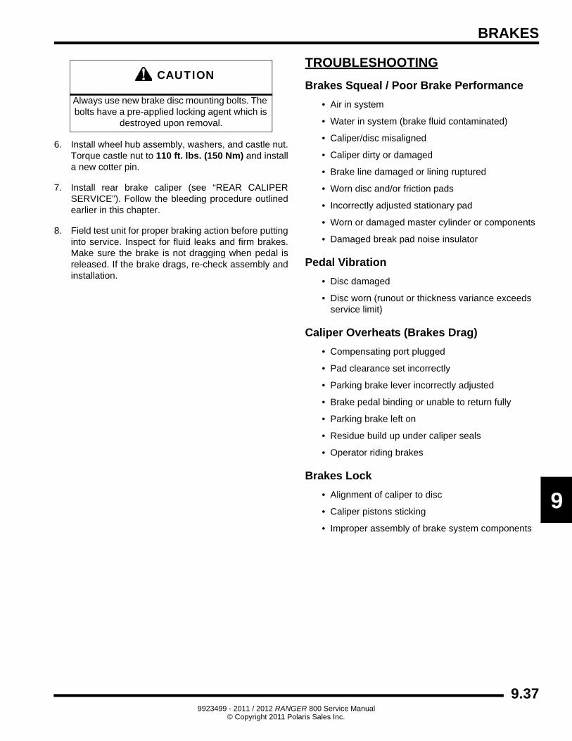
6. Install wheel hub assembly, washers, and castle nut. Torque castle nut to 110 ft. lbs. (150 Nm) and install a new cotter pin.
7. Install rear brake caliper (see “REAR CALIPER SERVICE”). Follow the bleeding procedure outlined earlier in this chapter.
8. Field test unit for proper braking action before putting into service. Inspect for fluid leaks and firm brakes. Make sure the brake is not dragging when pedal is released. If the brake drags, re-check assembly and installation.
TROUBLESHOOTING
Brakes Squeal / Poor Brake Performance
• Air in system
• Water in system (brake fluid contaminated)
• Caliper/disc misaligned
• Caliper dirty or damaged
• Brake line damaged or lining ruptured
• Worn disc and/or friction pads
• Incorrectly adjusted stationary pad
• Worn or damaged master cylinder or components
• Damaged break pad noise insulator
Pedal Vibration
• Disc damaged
• Disc worn (runout or thickness variance exceeds service limit)
Caliper Overheats (Brakes Drag)
• Compensating port plugged
• Pad clearance set incorrectly
• Parking brake lever incorrectly adjusted
• Brake pedal binding or unable to return fully
• Parking brake left on
• Residue build up under caliper seals
• Operator riding brakes
Brakes Lock
• Alignment of caliper to disc
• Caliper pistons sticking
• Improper assembly of brake system components
CAUTION
Always use new brake disc mounting bolts. The bolts have a pre-applied locking agent which is
destroyed upon removal.
9.379923499 - 2011 / 2012 RANGER 800 Service Manual
© Copyright 2011 Polaris Sales Inc.
BRAKES
NOTES
9.389923499 - 2011 / 2012 RANGER 800 Service Manual
© Copyright 2011 Polaris Sales Inc.