Embed Size (px)
Citation preview

Chapter 7
Column Design (Part 2)

Shearson Lehman/American Express Information Services Center, New York City. (Courtesy of Owen Steel Company, Inc.)

3
• Table 5.1 may not be suitable for practical design conditions
• e.g. when a column is part of a continuous frame

o Sidesway?
o Lateral deflection of building frame because of :• Lateral loads, or• Unsymmetrical vertical loads, or• Unsymmetrical frame
o Sidesway inhibited (braced frame), Fig. 7.1 (p. 214)• Braced by diagonal bracing , or• Braced by rigid shear wall
o Sidesway uninhibited ( moment frame)
o Alignment charts may help find k (the effective length factor)
o Fig 7.2 introduces the alignment chart produced by Jackson and Moreland

Figure 7.1 Sidesway inhibited.

A
B
g4
g1
g5
g6
g3
g2
g7
g8
c1
c2
c3 A : joint AB: joint BC1 column 1G1 girder 1 (beam)

Figure 7.3

To use the alignment chartsoPreliminary sizes for girders and columns framing into the column
in question is required
oAssuming E = 29000 ksi for all columns and girders, the G is
G = 10 for hinge support = 1 for fixed support

Figure 7.2 Jackson and Moreland alignment charts for effective lengths of columns in continuous frames.


Figure 7.4


Figure 7.2 Jackson and Moreland alignment charts for effective lengths of columns in continuous frames.

TABLE 7.1 Multipliers for Rigidly Attached Members

Figure 7.6 Steel shapes, including their I/L values.


If columns behave inelastically, then Ec = ET < E
And we define a stiffness reduction factor
Not applied for G=1 or G=10

Table 7.2 Stiffness Reduction Factor, τb
Source: AISC Manual, Table 4-21, p. 4-321, 14th ed., 2011. “Copyright © American Institute of Steel Construction. Reprinted with permission. All rights reserved”.


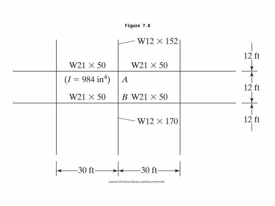
Figure 7.8


Base Plates• (Concentrically loaded columns)• Spread column load over sufficient area to prevent
overstressing of footing• Steel base• Welded, or• Bolted

Robins Air Force Base, GA. (Courtesy Britt Peters and Associates.)

Figure 7.13 Column base plates.

Figure 7.14

Figure 7.14

Define:
t = base plate thicknessA1 = base plate area = B x NA2= supporting concrete areaPp = nominal bearing strength of the concrete
Moment used to calculate t

When A1 covers A2
When A1 ≤ A2
Ωc = 2.31


𝑚=𝑁−0 .95𝑑
2
𝑛=𝐵−0 .8𝑏𝑓
2
=
≤ 1
λ𝑛 ′=λ√𝑑𝑏𝑓
4


Figure 7.15


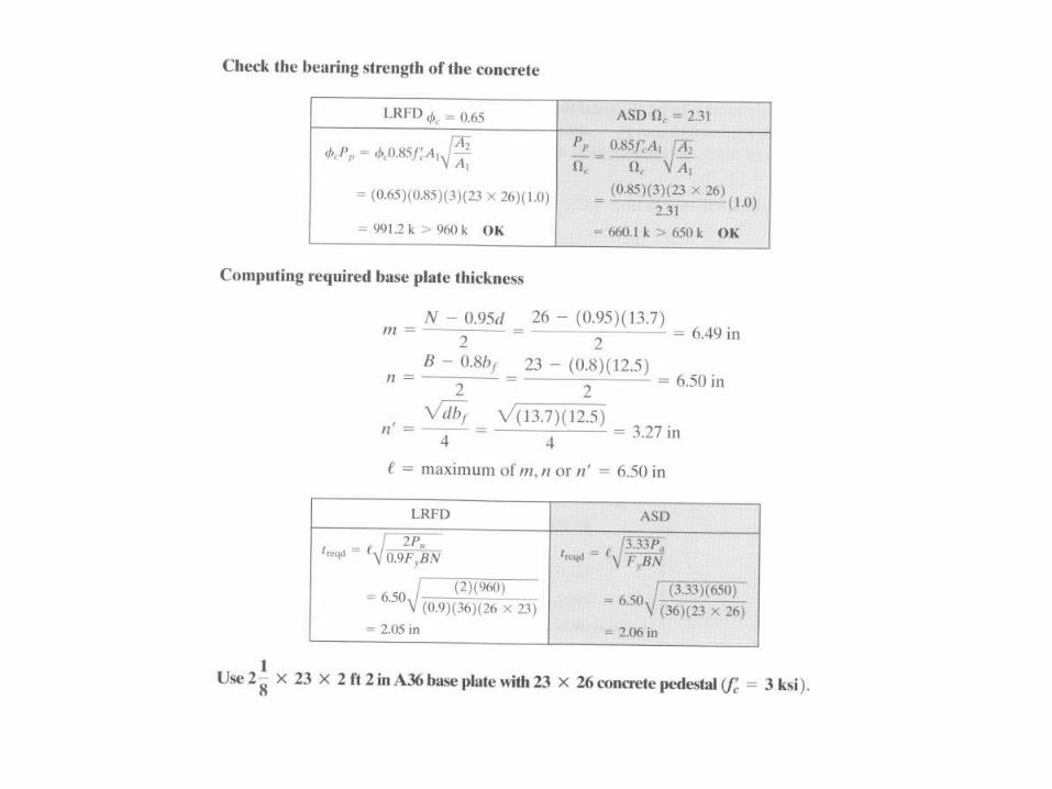


Figure 7.16

Homework # 6 problems: 7-3 (part a only) and 7-14

Figure P7-3