Embed Size (px)
Citation preview
Topics Covered in Chapter 66-1 : Finding Rrfor Series-Parallel Resistances
6-2: Resistance Strings in Parallel6-3: Resistance Banks in Series
6-4: Resistance Banks and Strings in Series-Parallel
@ 2ffi7 The McGrc*Hilt Cwanies Inc. All iskts rcm e il.
,:a::TF.r:.!qt:'ii-.! r.i.:T;11{,9'.':; f;.ri;-.:l'::,t:1+ylid;:l''fftli. i:,:r'.i'tl
::r;
iTcpfc-s Covered
a:
In Chapf,er 6
ri:l:
li'
iii:ll
,it{i
' t
' '
. j
t .
. ' A ZOOZ ire tut i i*U i t t Cirnp d n i e s, In c. Al I i gkt s re s n ed:
6-.[: FfndiftS Ru forSerfes-Pcrsilie[ Reslstan ces
. Overview of Series-Parallel Circuits. A series-parallel circuit, or combination circuit,
combines both series and parallel connections.r Most electronic circuits fall into this category.
Series-parallel circuits are typically used when differentvoltage and curent values are required from the samevoltage source.
. Series components form a series string.
r Parallel components form a parallel bank.
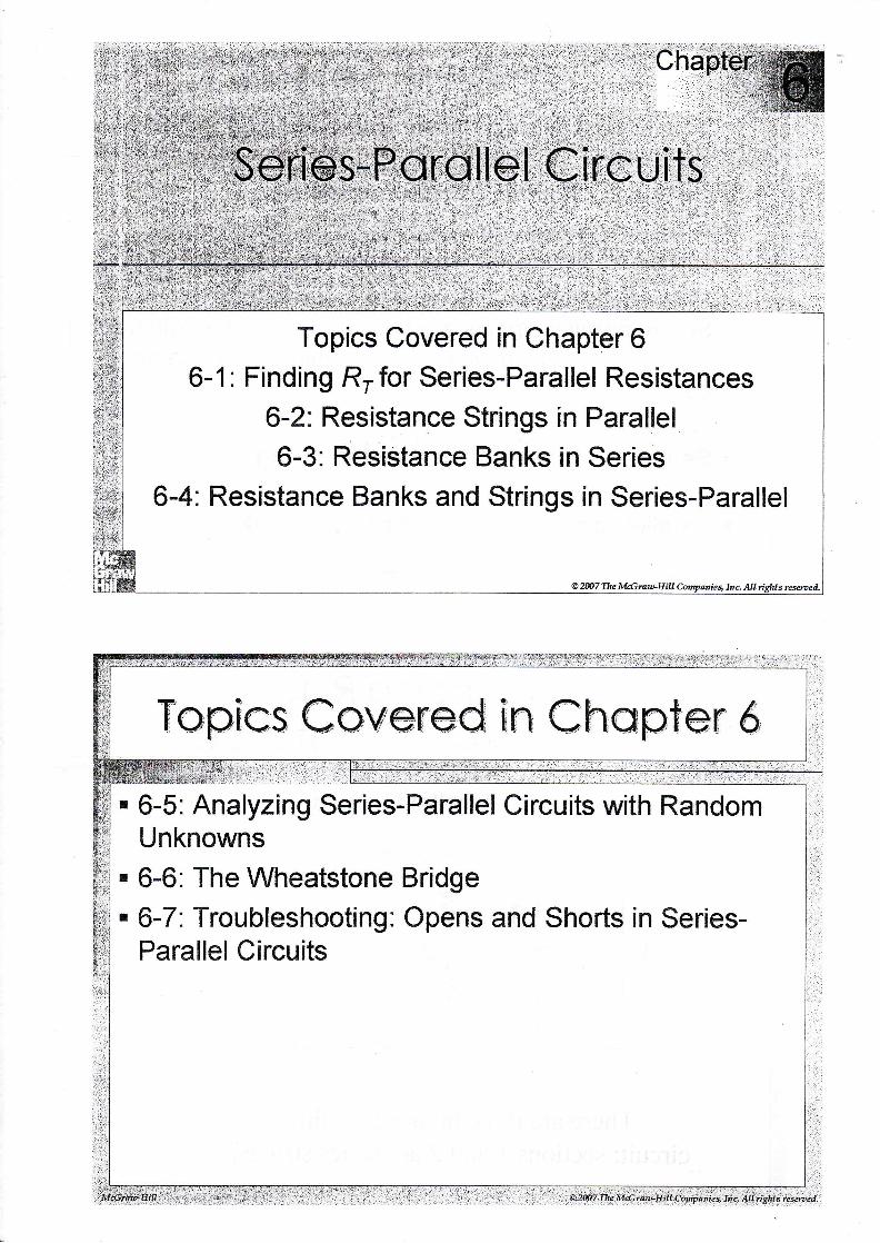
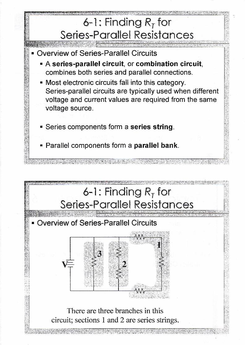
. Overview of Series-Parallel Circuits
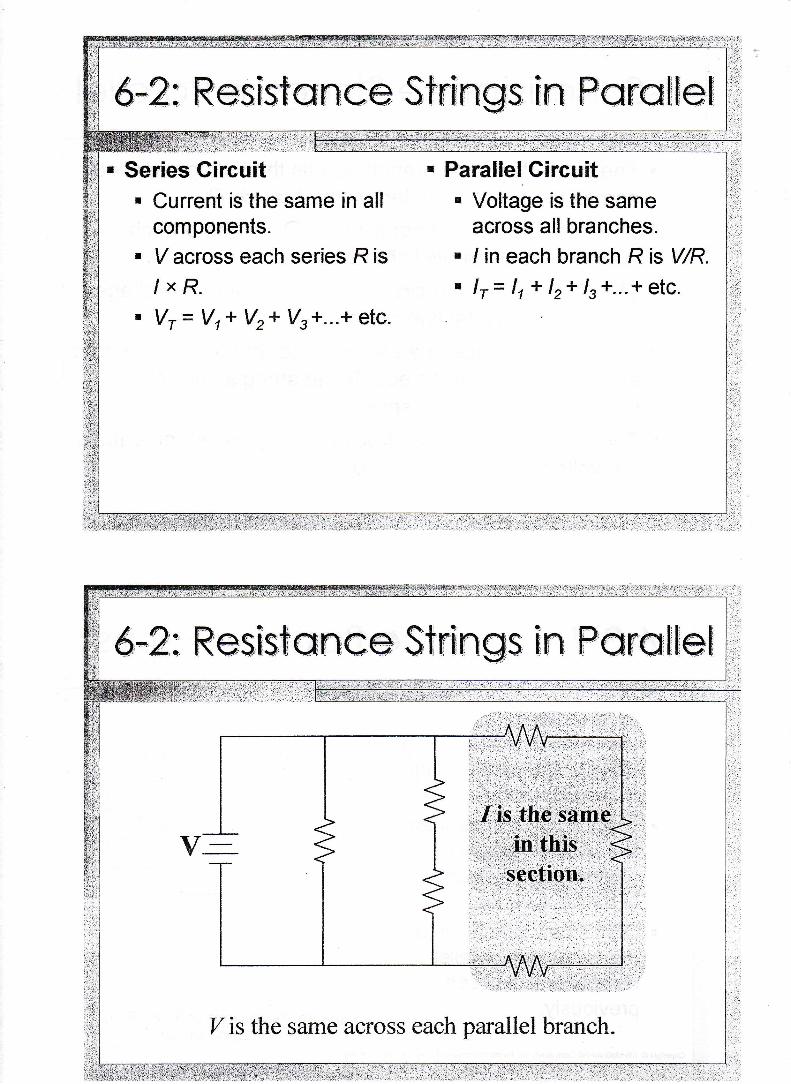
There are three branches in thiscircuit sections
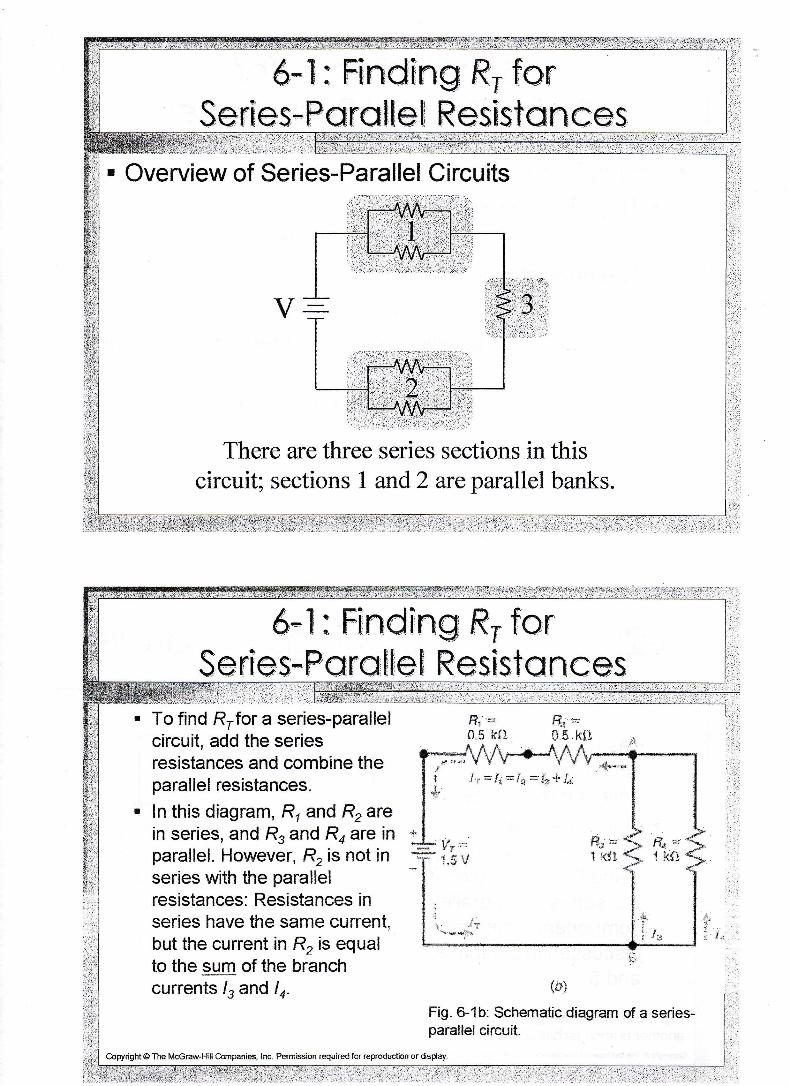
To find Rrfor a series-parallelcircuit, add the seriesresistances and combine theparallel resistances.f n this diagram, R, and Rrarein series, and R, and Ro are inparallel. However, R, is not inseries with the parallelresistances: Resistances inseries have the same current,but the current in R, is equalto the sum of the branchcurrents I, and ln.
f f ' l '=s.$ kf}
{#iFig. &1b. Schematic diagram of a series-parallel circuit.
&Hn.S . !rt}
.fa =.1; *,1;9 = &t + I*
Copyright @ The Mccraw-Ffill Cmpanies, lnc. PemisioB required for reproduction or dsday.
6--T: Ff*ding ftu f*nSeries-Pcra[fe] Reslsta rlces
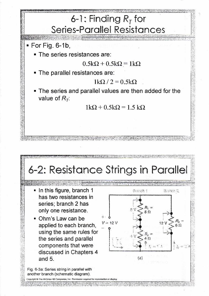
. For Fig. 6-1b,. The series resistances are:
0.5ko+0.5ko: lkft. The parallel resistances are:
lka I 2:0.5kQ. The series and parallel values are then added for the
value of Rr:lka + 0.5kfi: 1"5 kQ
: i : : ' . : r : i : : . ! : : . i ' - r l : i I. : ,1 - . - . : - . j : r ' - : . ; : i -
- i i ,_ : :
6*2: Resfs,f ff ft ce Strf n gs +
fft Parat$el
bir
#i:,-t:at:
itiliiitiiiii:t
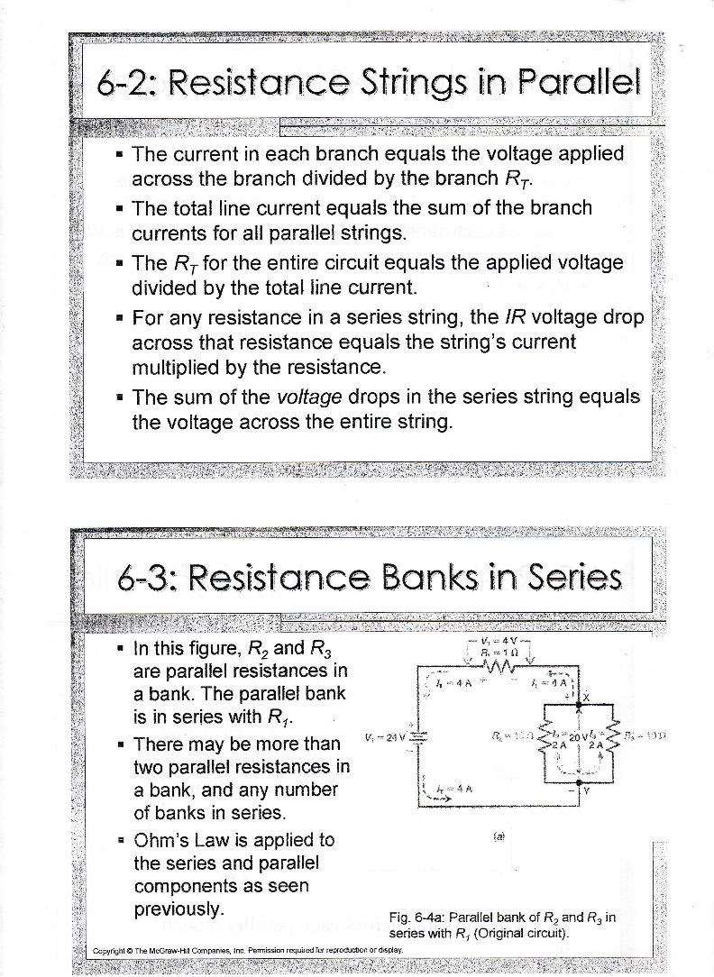
Series Gircuit. Current is the same in all
components.. V across each series R is
/xR.. Vr= Vr* Vza Vs+...+ etc.
Parallel Gircuit. Voltage is the same
across all branches.. I in each branch R is V/R.. l r ' l r + lz+ ls+. . .+ etc.
,ii
;ii
Z is the same across each parallel branch.
&*2: Resfsfafice Strfngs En Para[feli
. The current in each branch equals the voltage appliedacross the branch divided by the branch Rr.
. The total line current equals the sum of the branchcurrents for all parallel strings.
. The Rl- for the entire circuit equals the applied voltagedivided by the total line current.
r For any resistance in a series string, the /R voltage dropacross that resistance equals the string's currentmultiplied by the resistance.
. The sum of the valtage drops in the series string equalsthe voltage across the entire string.
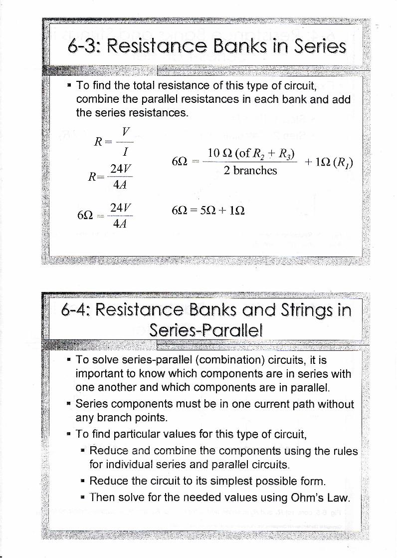
In this figure, R, and R.are parallel resistances ina bank. The parallel bankis in series with Rr.There may be more thantwo parallel resistances ina bank, and any numberof banks in series.Ohm's Law is applied tothe series and parallelcomponents as seenpreviously.
Fig. &4a: Parallel bank of R, and R. inserles with R, {Original circuit).
i :
;' ll1 '* 4Vi Fr '=1t l
@pyight@ The Mccraw-Ff ll Companies, Inc. Pemission requiredlar reptoductian or disday
6:3: Res$sfaftce Banks fn Sertes+;ii;?ii:rrl il
' To find the total resistance of this type of circuit,combine the parallel resistances in each bank and addthe series resistances.
I rr\ 10 A (ofR, + Rr)
rr z4v 6o:f f i +lo(Rr)n:
4A
6fl : 24v 6o:5cl + 1fl4A
: ; t . - : : -
-
' , ' ,
,S*fSjl$i, i i,:: .:.::!i.,:::,':','';,-'.::.'-':
To solve series-parallel (combination) circuits, it isimportant to know which components are in series withone another and which components are in parallel.Series components must be in one current path withoutany branch points.To find particular values for this type of circuit,r Reduce and combine the components using the rules
for individual series and paralfel circuits.r Reduce the circuit to its simplest possible form.
' Then solve for the needed values using Ohm's Law.
6-4: Resfstance tsanks and StrfngsSerfes-.Fg,rctIe"I
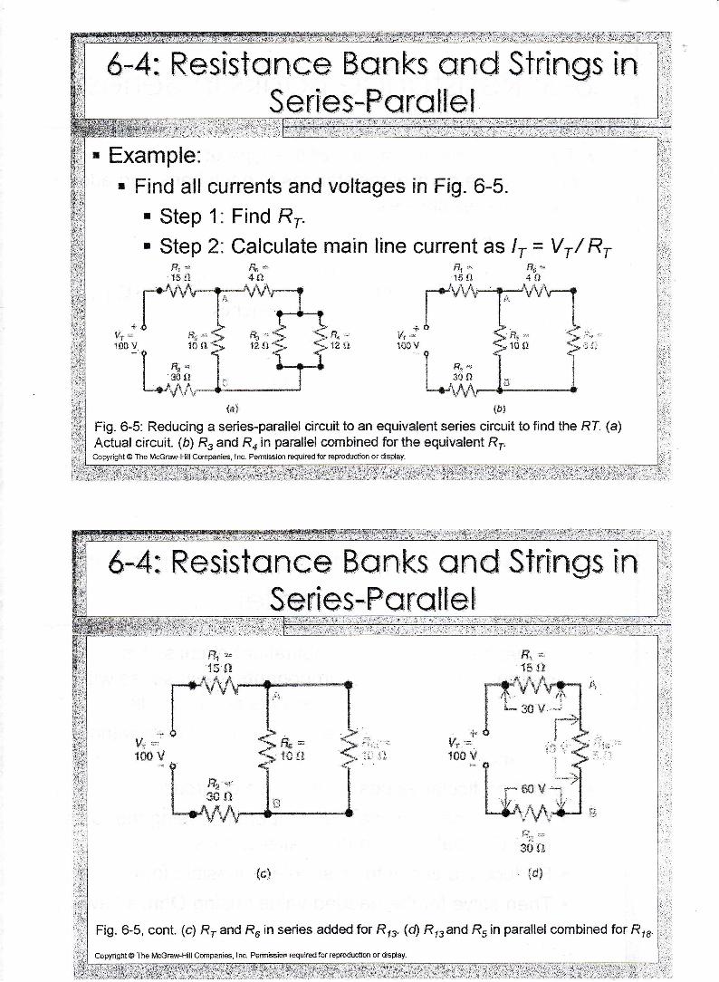
Example.r Find all currents and voltages in Fig. 6-5.
. Step 1. Find Rr.
' Step 2: Calculate main line current as /, = Vr/ R,
{d} tb}
Fig. 6-5: Reducing a series-parallel circuit to an equivalent series circuit to find the RL (a)Actual circuit. (b) Rs and R, in parallel cornbined for the equivalent RtCopyright @ The Mccraw.Ff ll Companies, lnc- Petmision required for reptoduction or disday.
f t r*5il JI
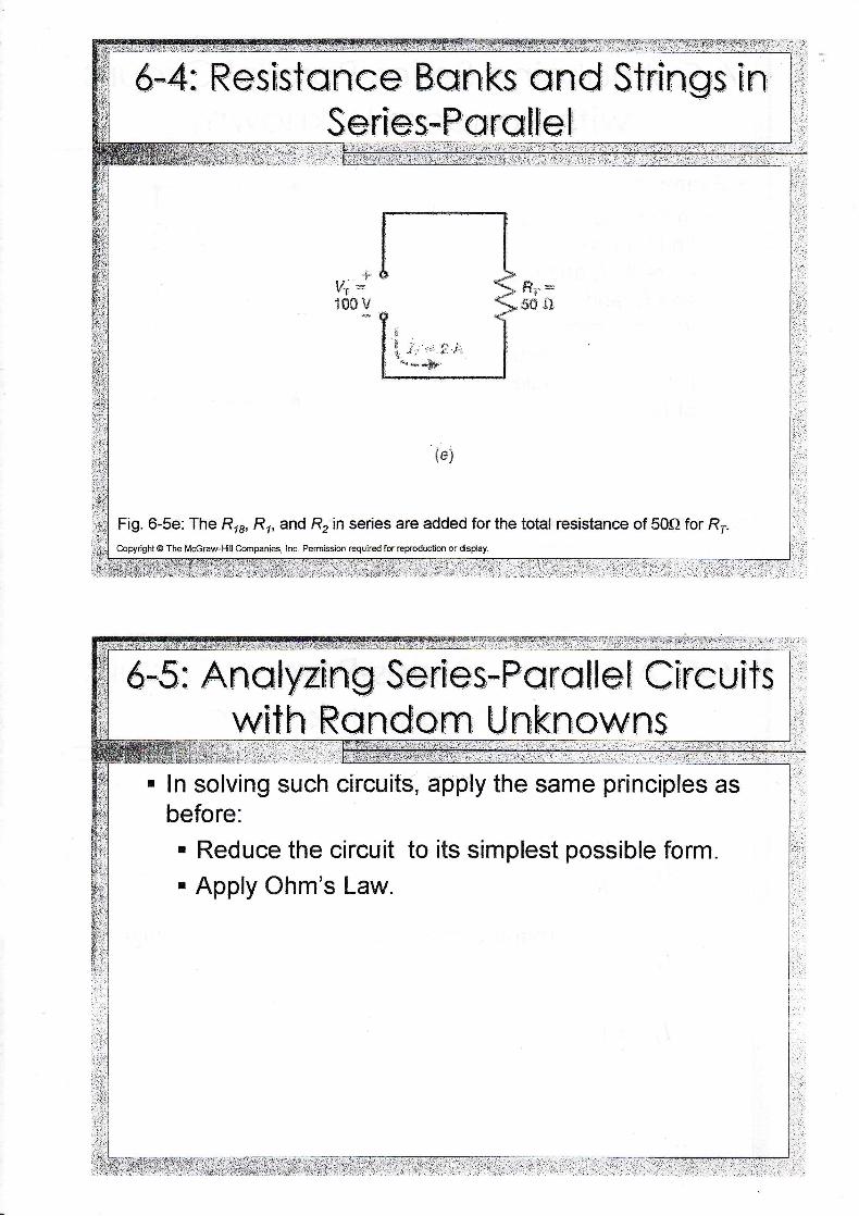
Fig. 6-5e: The Rrr, Rr, and R, in series are added for the total resistance of 50Q for R,Copydght @ The Mccmw-Ffill Compani$, Inc. Permission required for reproduction or dsday.
. In solving such circuits, apply the same principles asbefore:. Reduce the circuit to its simplest possible form.
' Apply Ohm's Law.
6'-5t Anafyzlng Sen[es--PcFs Jl e f Cfr"cu[tswlth Randonn Unknowns
.-. t.' :""'
6*5: Anatyzing SerFes-Pcrqffef Cfrcuffswlth Rsind:onn Unknowns
, , t . . . : . . ' . : . i : 1- ' r ,1 : , . . . -
I , t . , t . , , ,
t ' - - : : ' :
'
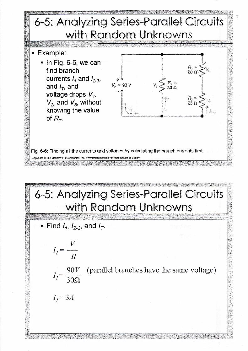
Example:. In Fig. 6-6, we can
find branchcurrents l, and lr_u,and /r, andvoltage drops Vr,Vr, and l/r, withoutknowing the valueof Rr.
Fig. 6-6: Finding all the cunents and voltages by calculating the branch cunents flrst.Copyright @ The Mccmw-Hill companies, Inc. Permission required for repoduction or dsplay.
6,-5: Ana Jynng S eries--Paratfef Cfrcuft-swfth Random Unknowns
r Find 11, 124, and lr.
gAY {parallel branches have the sanne voltage)30s
Tt1
I1
i : i : : , i :a i : j i . , : t , r i : : r : : : . r . : ; t : : : : . : : : : :
6-5: An alyzing Series-Porollel Circuitswith Rondom Unknowns
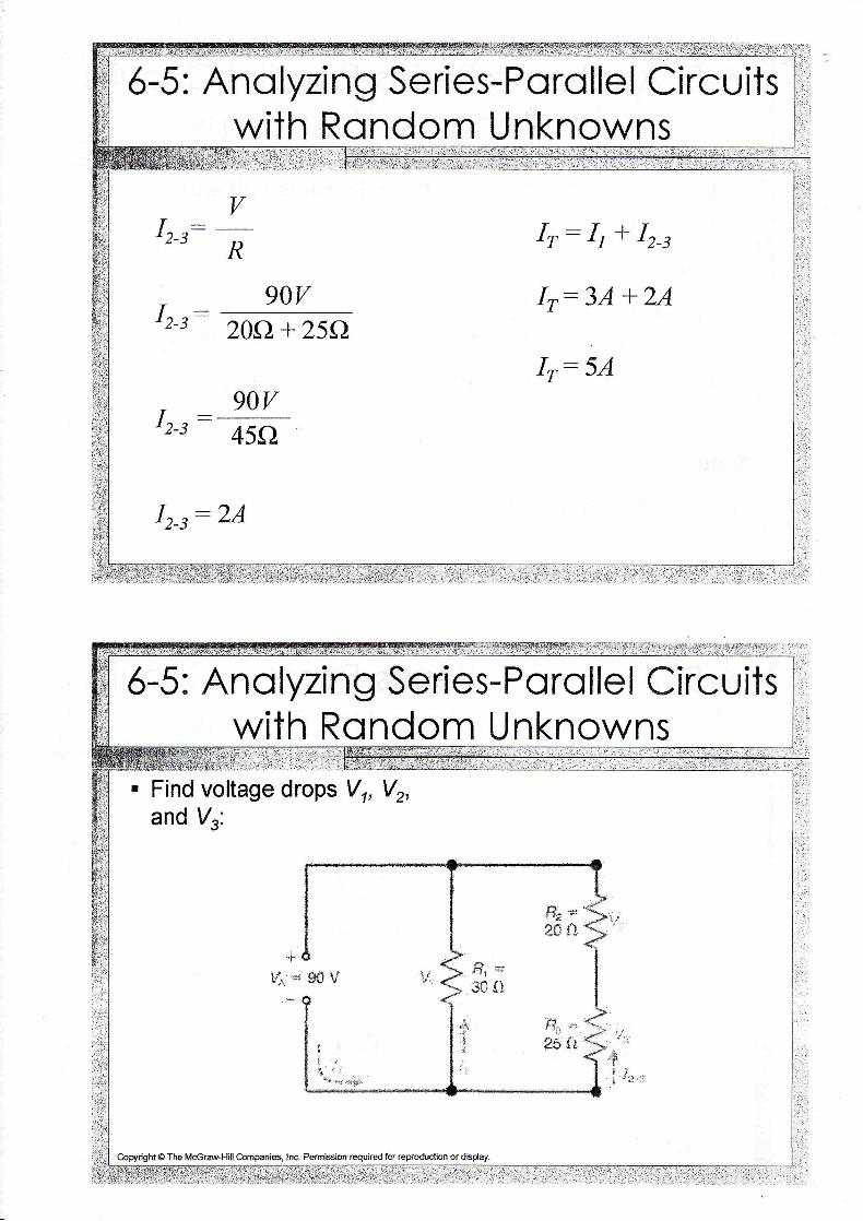
. Find voltage drops V1, V2,and
,.1-.
vs:
$, ,*;t* $t
. . f f r=* Jt i lJ
.j;t, ff." t-
: zs i r
copyright @ The Mccraw-Hill Companies, Ine. Permission required for reproduction ordsday.
6-5: Anolyzing Series-Parollel Circuitswith Rondom Unknowns
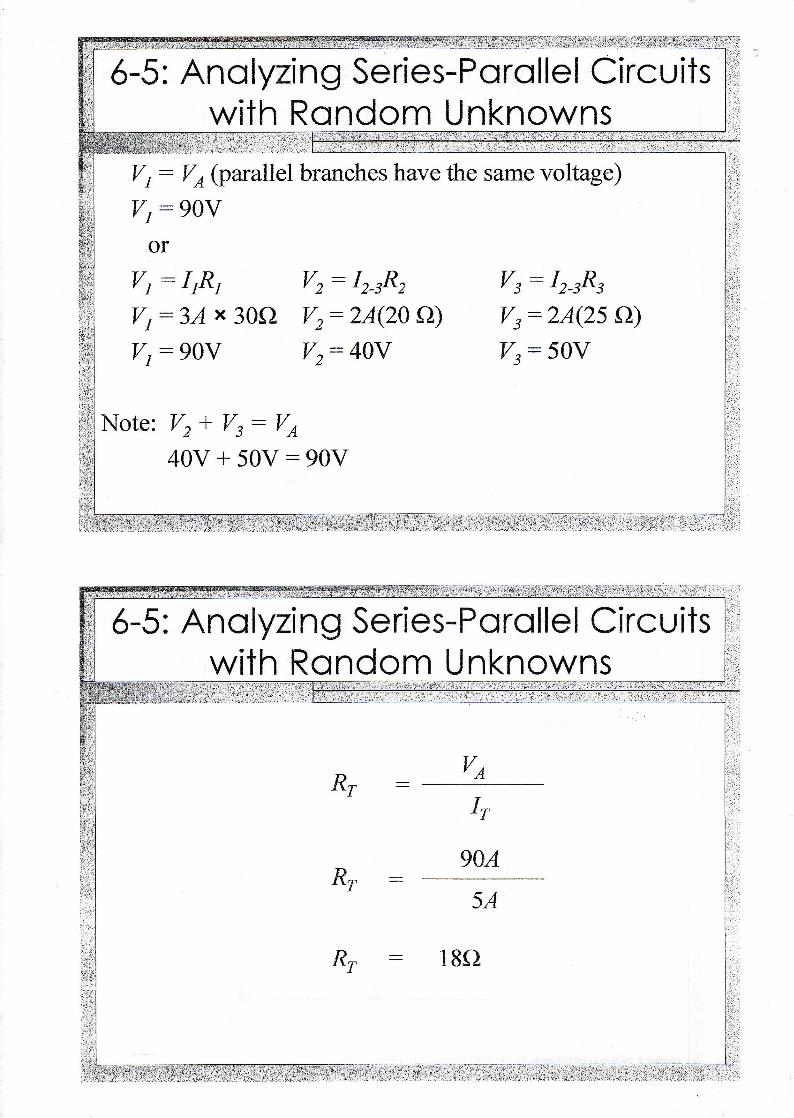
V r : Vo (parallel branches have the same voltage)
Vr:90V
or
Vt : IrR, Vz: Ir 8, Vs: I, ItVt : 34 x 30f} Vz: LA|ZA A) Vs:2A{25 O)
Vr :90V Vz:40V Ys:50V
Note: V, * Vs: Ve
40V + 50V:90V
904
Rr
Rr
ftr 18f}
&*&:The Whecfsfofte firfdge';.j.'1f..r;t,'',
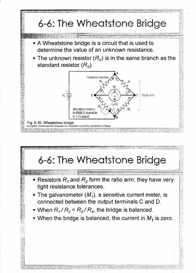
A Wheatstone bridge is a circuit that is used todetermine the value of an unknown resistance.The unknown resistor (R*) is in the same branch as thestandard resistor {Rr).
Fig. 6-10: Wheatstone bridge.Copyright @ The Mc€raw-l-lill companies, lnc. Permission reguired for reproduction or dsCay.
*tandard rcslsicr,il-*$gg llivsnlableln t-{t *lepc}
:-:- .1'.-.:
: - ' . , r . : . : , - , : , - . : i . l
Resistors Rr and R, form the ratiotig ht resistance tolerances.
they have very
The galvanometer (Mr), a sensitive current meter, isconnected between the output terminals C and D.When R',/ Rz= Rt/ Rn, the bridge is balanced.When the bridge is balanced, the current in M, is zero.
6-d: The Whee*fs,fofte Srtdge
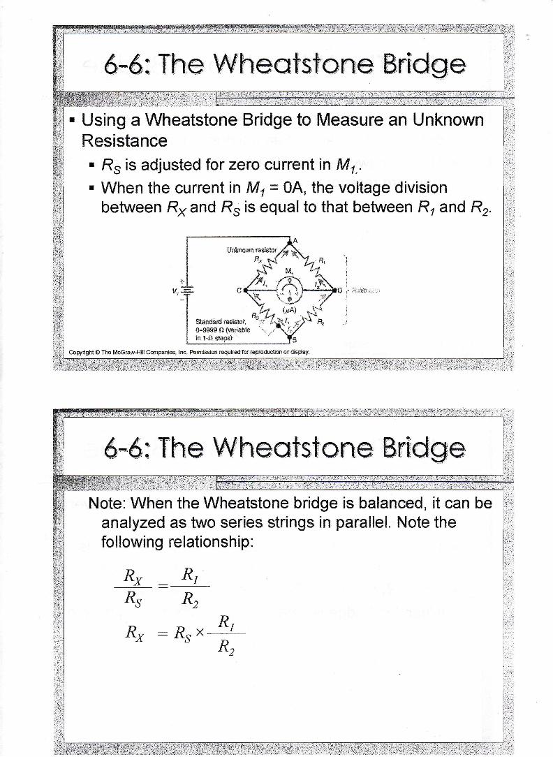
Using a Wheatstone Bridge to Measure an UnknownResistance' Rs is adjusted for zero current in Mt... When the current in M1= 04, the voltage division
between Rx and R* is equal to that between Rr and R .
Copyright@ The Mccraw]-lillCompanies, Inc- Permission requiredforreproducEon ordsday.
Stii.ndard r€sisBa,{Fg3$S $*,?dable 1 ..l* !-f:SeFl
Note: When the Wheatstone bridge is balanced,analyzed as two series strings in parallel. Note thefol lowing relationship:
R2
-RO* R,
dR2
Rs
RX
Rx RI
&-7: T,rcubtesha,effng: Opens andShorts En Ser[es-Pen'aftef C[rcults
. When troubleshooting series-parallel circuits, combinethe techniques used when troubleshooting individualseries and parallel circuits.
6,-7 : Troub,[eshooffng: Opens anid,Shorfs [n Serfes-Pcrqt[e[ Clrculf,s
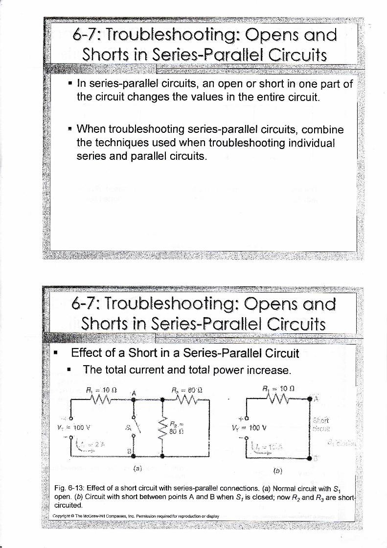
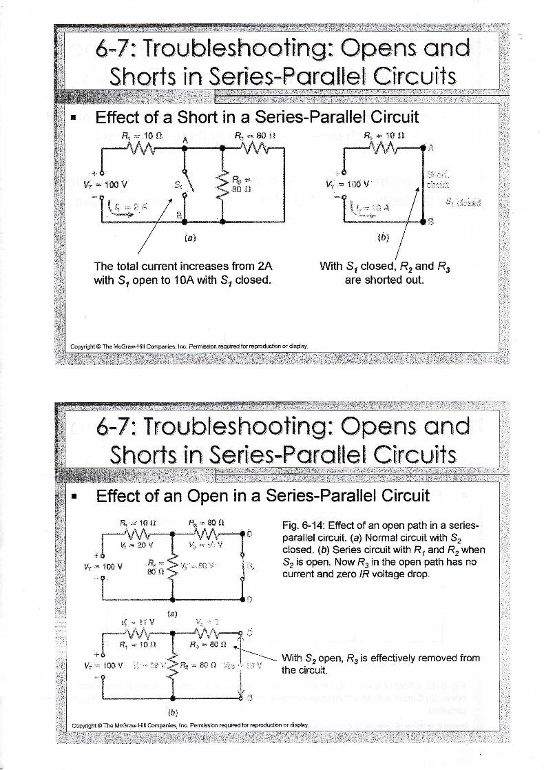
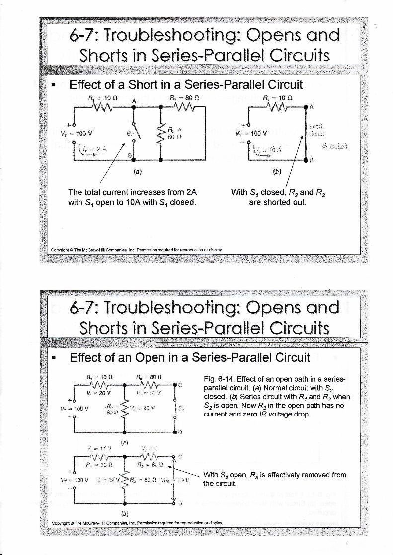
Effect of a Short in a Series-Parallel CircuitThe total current and total power increase.
f f r = fS{ i f le*SF91
,t
lf,r'r: ig6 U
{5}
Fig. 6-13: Effect of a short circuit with series-parallel connections. (a) Normal circuit with S,open. (b) Circuit with short between points A and B when S, is closed; now R, and R, arecircuited.
Copyright @ The McGril-Hill Cmpanies, Inc- Pemlssion required fd reproduction or dsday
Fi * 1${}
ii. i- !,i
&*7: Treub[esh*otfng: *pens cndShart,s [n Serfes*Pera[te[ Cfrcui,ts
in a Series-Parallel Circuit
Vr = "!*6- V
?r-=: , ;+"1;".4+
The total current increases from 2Awith S, open to l0Awith S, closed.
Copyright @ The Mccraw-Ffll Companies, Inc- Pem'rsslon rsquiredfor reproduction or dspfay.
t#:
With S? closed, R, and R,are shorted out.
&*7 : Troubfeshaat[nE: Opens andSharts [n Serfes-F€Nra[tet Cfrcufts
Effect of an Open in a Series-Parallel Circuit.F. * 1S ll t?* = 80 f!
!.: : tf 1,I
tftjcopyright @ The Mccr#Ffll Companies, I nc- Permbsion requit€d for reproduction or dsplay.
Fig. 6-14: Effect of an open path in a series-paralleleircuit. (a) Normalcircuit with Szclosed. (E) Series circuit with R, and R, whenS, is open. NowR, in the open path has nocurrent and zero /R voltage drop.
With 52 open, R, is effectively removed fromthe circuit.
9. *, 1$ !L &=8+f l
1fi* V ."; =" l$ t' = 8$ {i ;-.,:-.r i
&*7: Tr*ubfesho,cffng: Cper]s cndShorts Ser[es*Pera$tet Cfrculf, s
Short in a Series-Parallel Circuit
The total current increases from 2Awith S, open to l0Awith S, closed.
With S, closed, R, and R,are shorted out.
Copynght @ The Mccraw.Hill Companies, Inc. Permission tequircd for reproduclion or dsplay-
f f**1${ l
Effect of an Open in a Series-Parallel Circuit-Hr * 1S $1 fT* = $S fI
!.;. -: 1i lr I,r - -:
t
f r ,+ lgf i
tOS'V ',1 ." ltitl
€=** lJ{ :
ffz ,= SS fI ,;3r:l::
tft]copyright@ The Mc€r#Ffill Companies, Inc. Petmission required fot reptoduction or dsday.
Fig. 6-14: Effect of an open path in a series-parallel cireuit. (a) Normal circuit with Szclosed. (b) Series circuit with R, and R, whenS, is open. Now R, in the open path has nocunent and zero lR voltage drop.
With S? open, R, is efiectively removed fromthe circuit.
&-7 : Traubfeshcot[nE: Qpens qndShorts f n SerEes*Fcrat[ef Cfr-cufts
,#,t "'r ,'-:i; Y
it', .;,.** lf
&*7 : Tr:cu#esh*affng : Qpefts andShart's [n SenEes-Fers[te[ C[rcu[ts
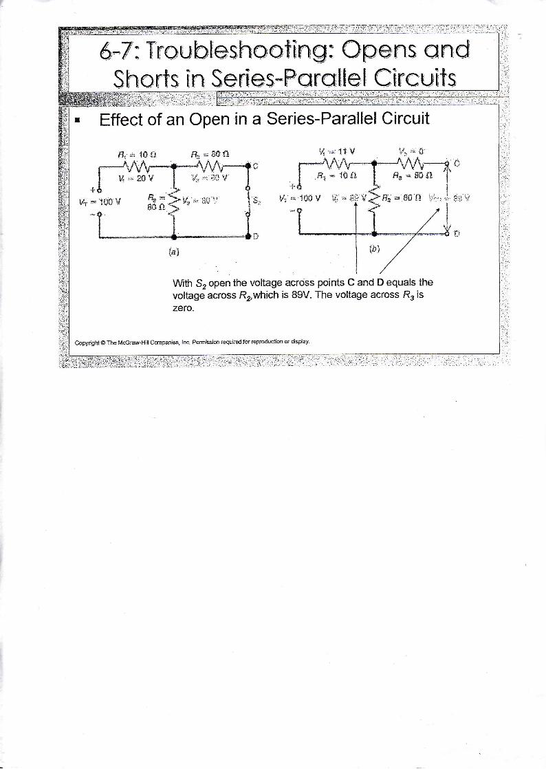
Effect of an Open in a Series-Parallel Circuit
Wth Sz open the voltage across points C and D equals thevoltage across Rowhich is 89V. The voltage across Rr iszero.
Copyright @ The McGraw-Hill Cmpanies, tnc Perm'rssion requited for reproductiot or dispay-
1'':i 'r; "itf
!d
f/s $F gS i,i