Embed Size (px)
Citation preview
6-1
CHAPTER 6
PRELIMINARY SURVEYS
List of Figures 6-2
Workflow 6-4
Initiation of Field Survey 6-4
Completion of Field Survey 6-4
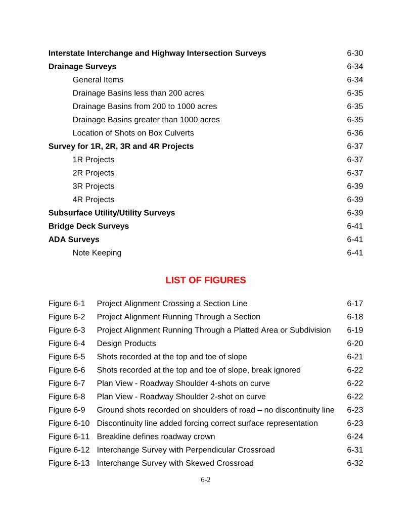
SDDOT Land Tie Symbols 6-5
SDDOT Survey Symbols 6-6
SDDOT Feature Code List 6-10
Feature Codes 6-14
Control Codes 6-14
Coding Example 6-15
Land Tie Surveys 6-15
Rural land tie surveys 6-16
Suburban land tie surveys 6-16
Urban land tie surveys 6-16
Project Alignment Crossing a Section Line 6-17
Project Alignment Running Through a Section 6-18
Project Alignment Running Through a Platted Area or Subdivision 6-19
Collecting Planimetric and Digital Terrain Model Data 6-20
Ground Shots 6-21
Discontinuity Lines and Breaklines 6-21
Topography and Surface General Standards 6-24
Note Keeping 6-26
Survey Data Requirements 6-27
File Management 6-27
Data Collector Files 6-28
Topography Data Furnished 6-28
Fieldbook Data Furnished 6-28
Geometry Data Furnished 6-29
Surface Data Furnished 6-29
6-2
Interstate Interchange and Highway Intersection Surveys 6-30
Drainage Surveys 6-34
General Items 6-34
Drainage Basins less than 200 acres 6-35
Drainage Basins from 200 to 1000 acres 6-35
Drainage Basins greater than 1000 acres 6-35
Location of Shots on Box Culverts 6-36
Survey for 1R, 2R, 3R and 4R Projects 6-37
1R Projects 6-37
2R Projects 6-37
3R Projects 6-39
4R Projects 6-39
Subsurface Utility/Utility Surveys 6-39
Bridge Deck Surveys 6-41
ADA Surveys 6-41
Note Keeping 6-41
LIST OF FIGURES
Figure 6-1 Project Alignment Crossing a Section Line 6-17
Figure 6-2 Project Alignment Running Through a Section 6-18
Figure 6-3 Project Alignment Running Through a Platted Area or Subdivision 6-19
Figure 6-4 Design Products 6-20
Figure 6-5 Shots recorded at the top and toe of slope 6-21
Figure 6-6 Shots recorded at the top and toe of slope, break ignored 6-22
Figure 6-7 Plan View - Roadway Shoulder 4-shots on curve 6-22
Figure 6-8 Plan View - Roadway Shoulder 2-shot on curve 6-22
Figure 6-9 Ground shots recorded on shoulders of road – no discontinuity line 6-23
Figure 6-10 Discontinuity line added forcing correct surface representation 6-23
Figure 6-11 Breakline defines roadway crown 6-24
Figure 6-12 Interchange Survey with Perpendicular Crossroad 6-31
Figure 6-13 Interchange Survey with Skewed Crossroad 6-32

6-3
Figure 6-14 Intersection Survey 6-33
Figure 6-15 Location of Shots on Box Culverts 6-36
Figure 6-16 2R Survey 6-38
Figure 6-17 2R Survey DTM 6-38
Figure 6-18 Survey Needs for ADA Requirements 6-42
Figure 6-19 Survey Shot Locations for Curb Ramps 6-43

6-4
WORKFLOW
Department of Transportation construction projects are scoped prior to beginning survey operations. The purpose of scoping each project is to define the limits of construction and assess any additional survey needs. The members of the scoping team should include the Office of Road Design - Engineering Supervisor and the Project Design Engineer; from the Office of Bridge Design - Engineering Supervisor and the Bridge Hydraulics Engineer if a structure is involved; the appropriate Region Engineer, Area Engineer and Maintenance Supervisor.
The appropriate Area Engineering Supervisor will be responsible for recording progress in the C2C program and provide monthly progress reports to the Office of Road Design so that a clear understanding as to the work that has been completed can be ascertained.
Initiation of Field Survey
The timeline established for the start and completion of field surveys is set by C2C or by direction from the Regional Engineer.
Completion of Field Survey
Upon completion of the field survey, the following survey notes and files are to be stored within the project folder within the appropriate Region folder on the U drive (U:\regionX\prj\cntyPCN#).
a. MicroStation design file (.dgn) b. InRoads Survey digital terrain model (.dtm) c. InRoads Survey geometry file (.alg) d. InRoads Survey fieldbook file (.fwd) e. Original bench and control level notes and check level notes f. All original unedited data collector job files used for project data collection
g. Comma separated value files (.csv) exported from each data collector job file
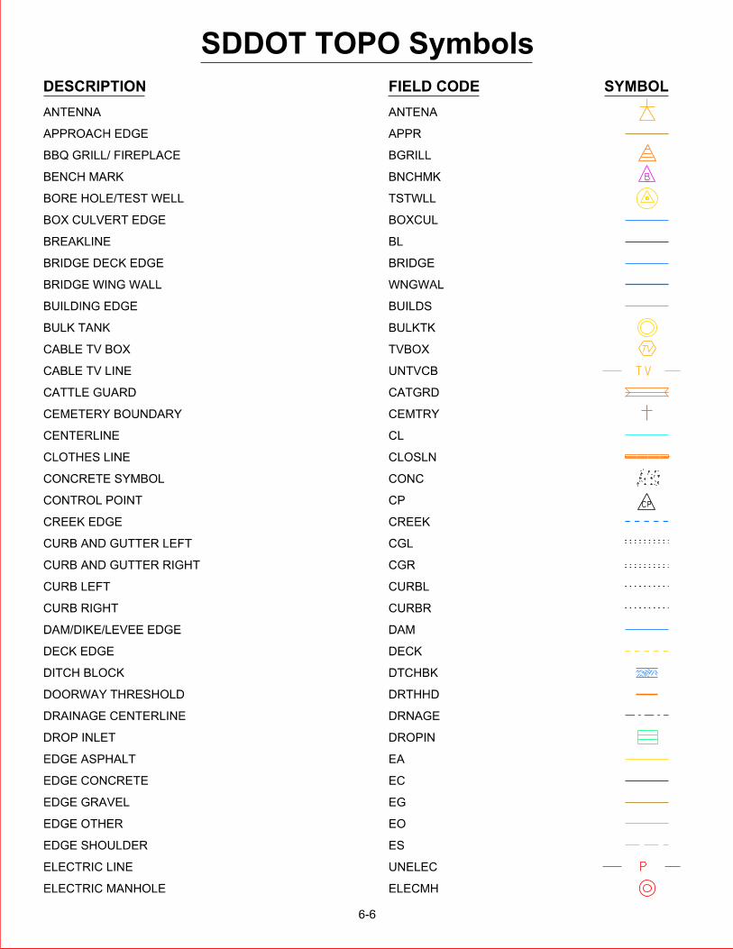
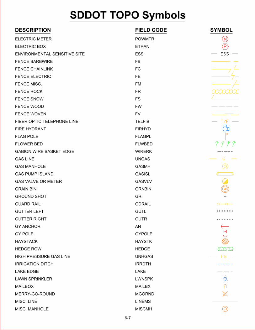
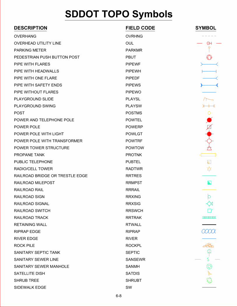
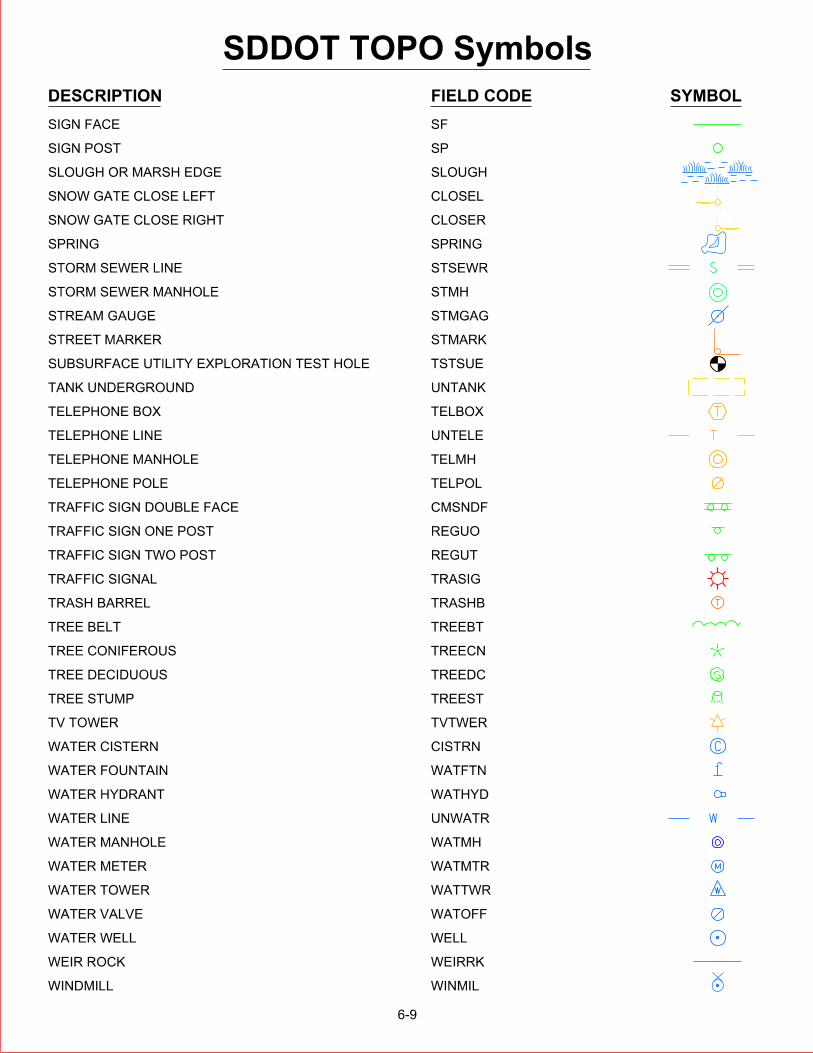
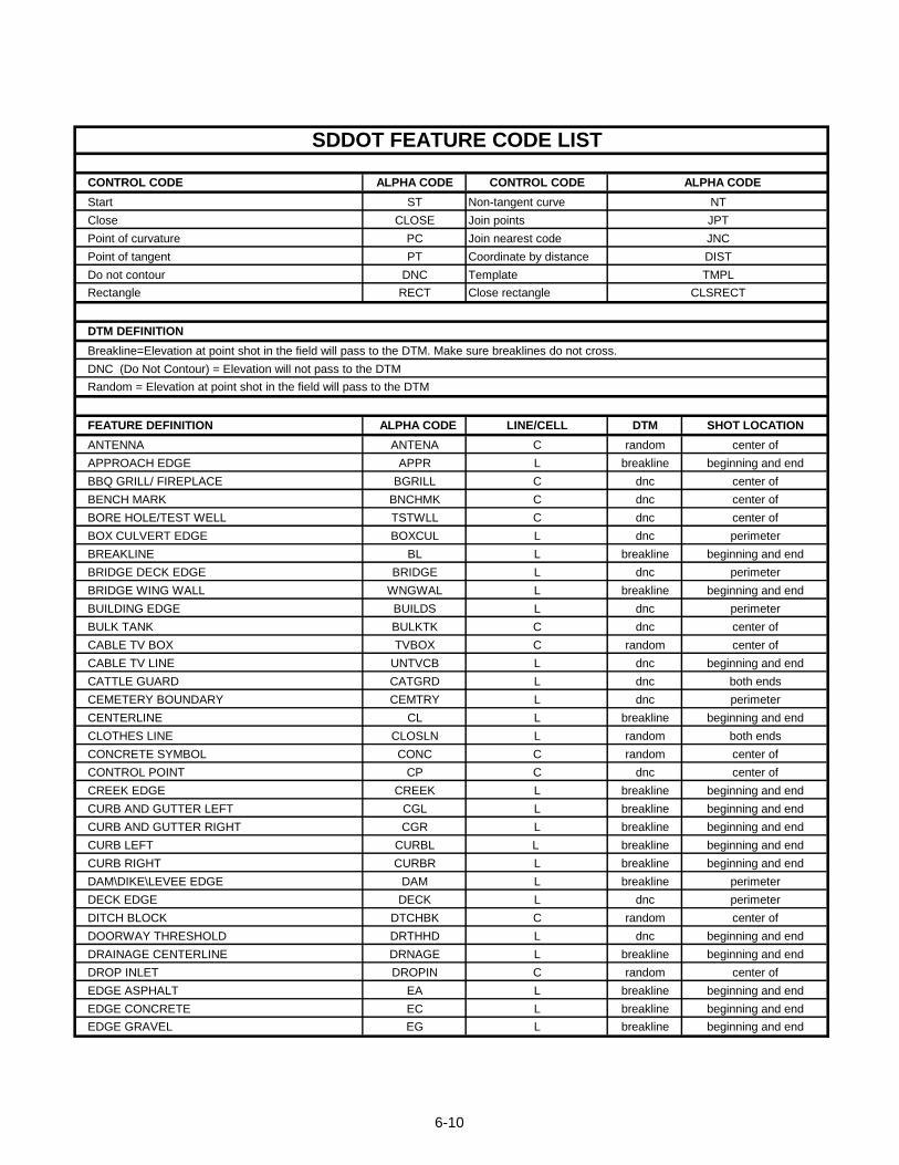
SDDOT FEATURE CODE LIST
CONTROL CODE ALPHA CODE CONTROL CODE ALPHA CODE
Start ST Non-tangent curve
Close CLOSE Join points
Point of curvature PC Join nearest code
Point of tangent PT Coordinate by distance
Do not contour DNC Template
Rectangle RECT Close rectangle
DTM DEFINITION
Breakline=Elevation at point shot in the field will pass to the DTM. Make sure breaklines do not cross.
DNC (Do Not Contour) = Elevation will not pass to the DTM
Random = Elevation at point shot in the field will pass to the DTM
FEATURE DEFINITION ALPHA CODE LINE/CELL DTM SHOT LOCATION
ANTENNA ANTENA C random center of
APPROACH EDGE APPR L breakline beginning and end
BBQ GRILL/ FIREPLACE BGRILL C dnc center of
BENCH MARK BNCHMK C dnc center of
BORE HOLE/TEST WELL TSTWLL C dnc center of
BOX CULVERT EDGE BOXCUL L dnc perimeter
BREAKLINE BL L breakline beginning and end
BRIDGE DECK EDGE BRIDGE L dnc perimeter
BRIDGE WING WALL WNGWAL L breakline beginning and end
BUILDING EDGE BUILDS L dnc perimeter
BULK TANK BULKTK C dnc center of
CABLE TV BOX TVBOX C random center of
CABLE TV LINE UNTVCB L dnc beginning and end
CATTLE GUARD CATGRD L dnc both ends
CEMETERY BOUNDARY CEMTRY L dnc perimeter
CENTERLINE CL L breakline beginning and end
CLOTHES LINE CLOSLN L random both ends
CONCRETE SYMBOL CONC C random center of
CONTROL POINT CP C dnc center of
CREEK EDGE CREEK L breakline beginning and end
CURB AND GUTTER LEFT CGL L breakline beginning and end
CURB AND GUTTER RIGHT CGR L breakline beginning and end
CURB LEFT CURBL L breakline beginning and end
CURB RIGHT CURBR L breakline beginning and end
DAM\DIKE\LEVEE EDGE DAM L breakline perimeter
DECK EDGE DECK L dnc perimeter
DITCH BLOCK DTCHBK C random center of
DOORWAY THRESHOLD DRTHHD L dnc beginning and end
DRAINAGE CENTERLINE DRNAGE L breakline beginning and end
DROP INLET DROPIN C random center of
EDGE ASPHALT EA L breakline beginning and end
EDGE CONCRETE EC L breakline beginning and end
EDGE GRAVEL EG L breakline beginning and end
CLSRECT
NT
JPT
JNC
DIST
TMPL
6-10
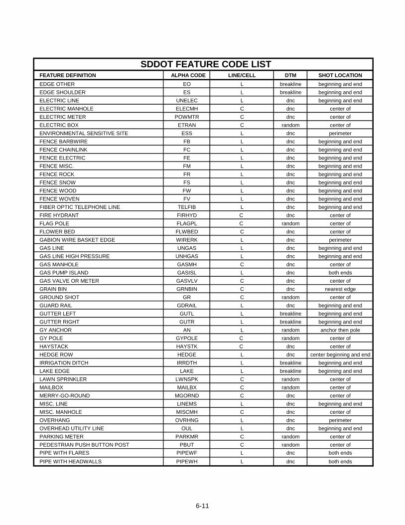
SDDOT FEATURE CODE LIST FEATURE DEFINITION ALPHA CODE LINE/CELL DTM SHOT LOCATION
EDGE OTHER EO L breakline beginning and end
EDGE SHOULDER ES L breakline beginning and end
ELECTRIC LINE UNELEC L dnc beginning and end
ELECTRIC MANHOLE ELECMH C dnc center of
ELECTRIC METER POWMTR C dnc center of
ELECTRIC BOX ETRAN C random center of
ENVIRONMENTAL SENSITIVE SITE ESS L dnc perimeter
FENCE BARBWIRE FB L dnc beginning and end
FENCE CHAINLINK FC L dnc beginning and end
FENCE ELECTRIC FE L dnc beginning and end
FENCE MISC. FM L dnc beginning and end
FENCE ROCK FR L dnc beginning and end
FENCE SNOW FS L dnc beginning and end
FENCE WOOD FW L dnc beginning and end
FENCE WOVEN FV L dnc beginning and end
FIBER OPTIC TELEPHONE LINE TELFIB L dnc beginning and end
FIRE HYDRANT FIRHYD C dnc center of
FLAG POLE FLAGPL C random center of
FLOWER BED FLWBED C dnc center of
GABION WIRE BASKET EDGE WIRERK L dnc perimeter
GAS LINE UNGAS L dnc beginning and end
GAS LINE HIGH PRESSURE UNHGAS L dnc beginning and end
GAS MANHOLE GASMH C dnc center of
GAS PUMP ISLAND GASISL L dnc both ends
GAS VALVE OR METER GASVLV C dnc center of
GRAIN BIN GRNBIN C dnc nearest edge
GROUND SHOT GR C random center of
GUARD RAIL GDRAIL L dnc beginning and end
GUTTER LEFT GUTL L breakline beginning and end
GUTTER RIGHT GUTR L breakline beginning and end
GY ANCHOR AN L random anchor then pole
GY POLE GYPOLE C random center of
HAYSTACK HAYSTK C dnc center of
HEDGE ROW HEDGE L dnc center beginning and end
IRRIGATION DITCH IRRDTH L breakline beginning and end
LAKE EDGE LAKE L breakline beginning and end
LAWN SPRINKLER LWNSPK C random center of
MAILBOX MAILBX C random center of
MERRY-GO-ROUND MGORND C dnc center of
MISC. LINE LINEMS L dnc beginning and end
MISC. MANHOLE MISCMH C dnc center of
OVERHANG OVRHNG L dnc perimeter
OVERHEAD UTILITY LINE OUL L dnc beginning and end
PARKING METER PARKMR C random center of
PEDESTRIAN PUSH BUTTON POST PBUT C random center of
PIPE WITH FLARES PIPEWF L dnc both ends
PIPE WITH HEADWALLS PIPEWH L dnc both ends
6-11
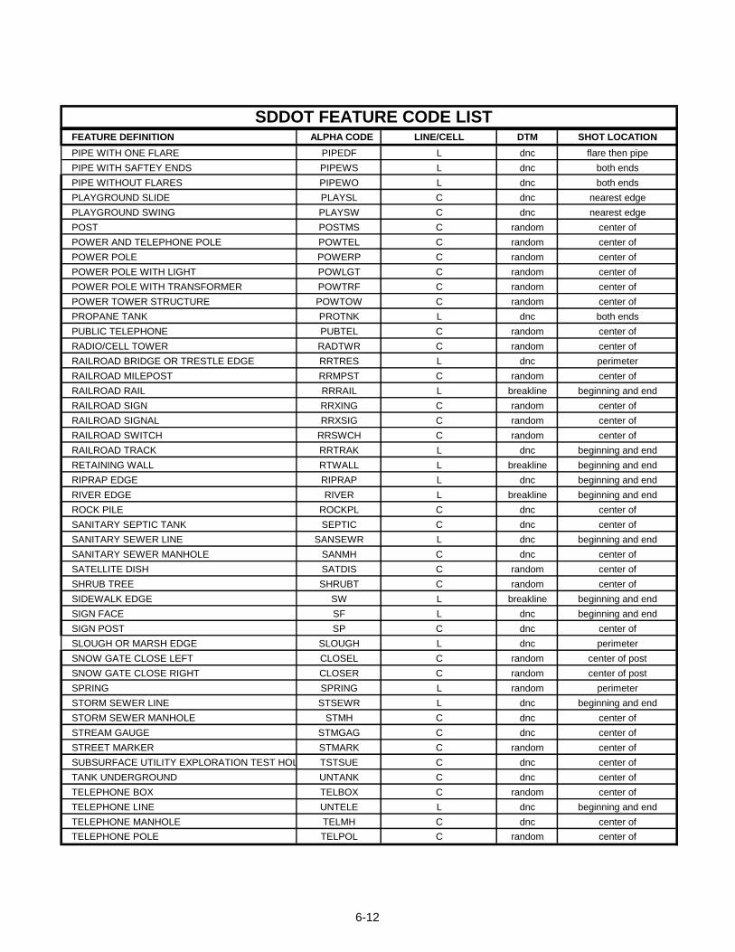
SDDOT FEATURE CODE LIST FEATURE DEFINITION ALPHA CODE LINE/CELL DTM SHOT LOCATION
PIPE WITH ONE FLARE PIPEDF L dnc flare then pipe
PIPE WITH SAFTEY ENDS PIPEWS L dnc both ends
PIPE WITHOUT FLARES PIPEWO L dnc both ends
PLAYGROUND SLIDE PLAYSL C dnc nearest edge
PLAYGROUND SWING PLAYSW C dnc nearest edge
POST POSTMS C random center of
POWER AND TELEPHONE POLE POWTEL C random center of
POWER POLE POWERP C random center of
POWER POLE WITH LIGHT POWLGT C random center of
POWER POLE WITH TRANSFORMER POWTRF C random center of
POWER TOWER STRUCTURE POWTOW C random center of
PROPANE TANK PROTNK L dnc both ends
PUBLIC TELEPHONE PUBTEL C random center of
RADIO/CELL TOWER RADTWR C random center of
RAILROAD BRIDGE OR TRESTLE EDGE RRTRES L dnc perimeter
RAILROAD MILEPOST RRMPST C random center of
RAILROAD RAIL RRRAIL L breakline beginning and end
RAILROAD SIGN RRXING C random center of
RAILROAD SIGNAL RRXSIG C random center of
RAILROAD SWITCH RRSWCH C random center of
RAILROAD TRACK RRTRAK L dnc beginning and end
RETAINING WALL RTWALL L breakline beginning and end
RIPRAP EDGE RIPRAP L dnc beginning and end
RIVER EDGE RIVER L breakline beginning and end
ROCK PILE ROCKPL C dnc center of
SANITARY SEPTIC TANK SEPTIC C dnc center of
SANITARY SEWER LINE SANSEWR L dnc beginning and end
SANITARY SEWER MANHOLE SANMH C dnc center of
SATELLITE DISH SATDIS C random center of
SHRUB TREE SHRUBT C random center of
SIDEWALK EDGE SW L breakline beginning and end
SIGN FACE SF L dnc beginning and end
SIGN POST SP C dnc center of
SLOUGH OR MARSH EDGE SLOUGH L dnc perimeter
SNOW GATE CLOSE LEFT CLOSEL C random center of post
SNOW GATE CLOSE RIGHT CLOSER C random center of post
SPRING SPRING L random perimeter
STORM SEWER LINE STSEWR L dnc beginning and end
STORM SEWER MANHOLE STMH C dnc center of
STREAM GAUGE STMGAG C dnc center of
STREET MARKER STMARK C random center of
SUBSURFACE UTILITY EXPLORATION TEST HOLE TSTSUE C dnc center of
TANK UNDERGROUND UNTANK C dnc center of
TELEPHONE BOX TELBOX C random center of
TELEPHONE LINE UNTELE L dnc beginning and end
TELEPHONE MANHOLE TELMH C dnc center of
TELEPHONE POLE TELPOL C random center of
6-12
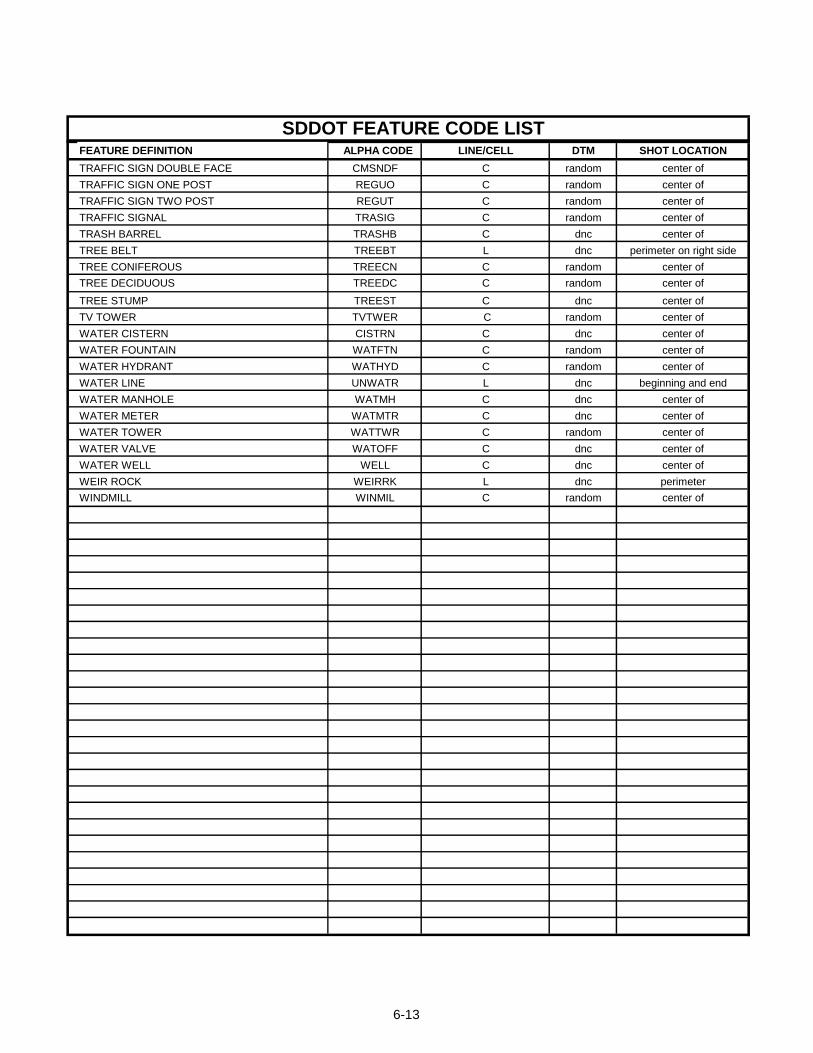
SDDOT FEATURE CODE LIST FEATURE DEFINITION ALPHA CODE LINE/CELL DTM SHOT LOCATION
TRAFFIC SIGN DOUBLE FACE CMSNDF C random center of
TRAFFIC SIGN ONE POST REGUO C random center of
TRAFFIC SIGN TWO POST REGUT C random center of
TRAFFIC SIGNAL TRASIG C random center of
TRASH BARREL TRASHB C dnc center of
TREE BELT TREEBT L dnc perimeter on right side
TREE CONIFEROUS TREECN C random center of
TREE DECIDUOUS TREEDC C random center of
TREE STUMP TREEST C dnc center of
TV TOWER TVTWER C random center of
WATER CISTERN CISTRN C dnc center of
WATER FOUNTAIN WATFTN C random center of
WATER HYDRANT WATHYD C random center of
WATER LINE UNWATR L dnc beginning and end
WATER MANHOLE WATMH C dnc center of
WATER METER WATMTR C dnc center of
WATER TOWER WATTWR C random center of
WATER VALVE WATOFF C dnc center of
WATER WELL WELL C dnc center of
WEIR ROCK WEIRRK L dnc perimeter
WINDMILL WINMIL C random center of
6-13
6-14
FEATURE CODES
Control Codes Control codes are like verbs in the English language; they denote an action. These control codes are independent of feature codes and can be applied to all feature codes. Shown below is a brief description of the action each control code serves. ST - Defines the beginning of a feature line string and only needs to be associated with the first feature code of the line string. When a new line string is started this control code will need t o be associated with the first feature code in the line string. CLOSE – Defines the end of a feature line string and connects the first and last field points to form a closed shape. PC - Defines the beginning of a curve or point of curvature for a curvilinear feature. PT - Defines the end of a curve or point of tangency for a curvilinear feature. DNC - Specifies a field point will be excluded from triangulation of the surface. This control code will not work for feature line points. RECT - creates a rectangle based on two field points and a given distance. Positive distance will place rectangle right of the field points and negative distance will place rectangle left of the field points from the direction the field points were collected. CLSRECT - creates a rectangle based on three field points. JPT - Connects a feature line from the field point the control code is associated with to a field point number specified following the JPT control code. This control code requires a space between the control code and the field point number to connect to. A maximum of eight field points can be connected to the associated control code field point. Example: BL1 JPT 1097 1098 1163 1189 572 847 369 798 JNC – Connects a feature line from the field point the control code is associated with to the nearest point with the specified code following the JNC control code. This control code requires a space between the control code and the feature code to join to. Example: EC3 JNC EA1 NT - specifies that a curve is non-tangent to the incoming or outgoing line segment. This code is used in conjunction with the PC and/or PT control codes. DIST - Creates a linear feature where all angles are perpendicular to the previous line segment. This control code requires two field points and taped distances to build the shape.
6-15
TMPL - specifies where the template starts and controls the number of observations required across the template. Coding Example Feature line strings will require a feature line code followed by the control code (ST) associated with the first field point of the desired feature line string. For example, when locating the edge of an asphalt surface, the initial shot will be coded EA1 ST. The shots following will not require the ST control code, they will simply be coded EA1, this will continue until the final shot along the asphalt edge has been collected. There is no control code needed to end the feature line string. To reuse the EC1 feature line code on a different edge of asphalt use the feature line code EC1 followed by the control code ST.
LAND TIE SURVEYS
Land tie surveys are initiated during the preliminary phase of the project and concern the accurate location and calculation of Public Lands Survey System (PLSS) corners, Right of Way (ROW) corners and property corners. This type of survey is to be performed by or under the direction of a Land Surveyor licensed in the State of South Dakota. It is of the utmost importance that accurate and properly located or calculated PLSS, ROW and property corners be supplied within the land tie survey as new right of way required for future highway construction will be based on the land tie survey information. Local residents and property owners should be interviewed, if necessary, to acquire additional information regarding PLSS, ROW and property corner locations. All PLSS, ROW and property corners must be referenced to the project primary control. This will ensure the land tie survey, preliminary topography survey and preliminary design use the same survey datum and coordinates throughout the stages of the project’s development. Railroad maps are a useful resource in locating or reestablishing PLSS, ROW and property corners. These maps are readily available and can be obtained from the Right of Way Specialist in the Office of Road Design. Send scans, paper copies or the originals of all plans, plats, and any other information that was used by the Registered Land Surveyor to locate or calculate PLSS, ROW and property corners to the Office of Road Design. For urban projects, these copies can be an excellent reference to show what corners were looked for and what corners were found and calculated.
6-16
All land tie notes should include, but not be limited to, the type of corner found (section corner, quarter corner, etc.), type of monument found, markings on the monument and any physical evidence that was used to calculate and reestablish a lost or obliterated corner. For reference, every Region Land Surveyor’s Office has a copy of the "Manual of Instructions for the Survey of Public Lands of the United States, 1973 and 2009", published by the Bureau of Land Management, U.S. Department of Interior. The Office of Road Design Land Surveyor should be contacted concerning any problems or questions concerning private and public boundaries that may arise during the land tie survey. Rural land tie survey
Region Land Surveyor to provide full Public Lands Survey System (PLSS) breakdown to include found monuments and calculated lost or obliterated corner locations. Suburban land tie survey Region Land Surveyor to provide full Public Lands Survey (PLSS) section breakdown to include found monuments and calculated lost or obliterated corner locations. As well as found monuments and calculated subdivision corners and addition corners. Urban land tie survey Region Land Surveyor to provide found monuments and calculated block corners, subdivision corners and addition corners. Region Land Surveyors to use a best fit method to determine the boundary line location in urban areas where many monuments are located and when used as the corners location creates many PI’s resulting in an undesirable boundary line. a. Block to block best fit method - A best fit line through found monuments within a
single block. b. Subdivision to Subdivision best fit method – A best fit line through found
monuments within a platted subdivision, addition, etc. This method is to be used when not enough monumentation is found to use the block to block best fit method.
6-17
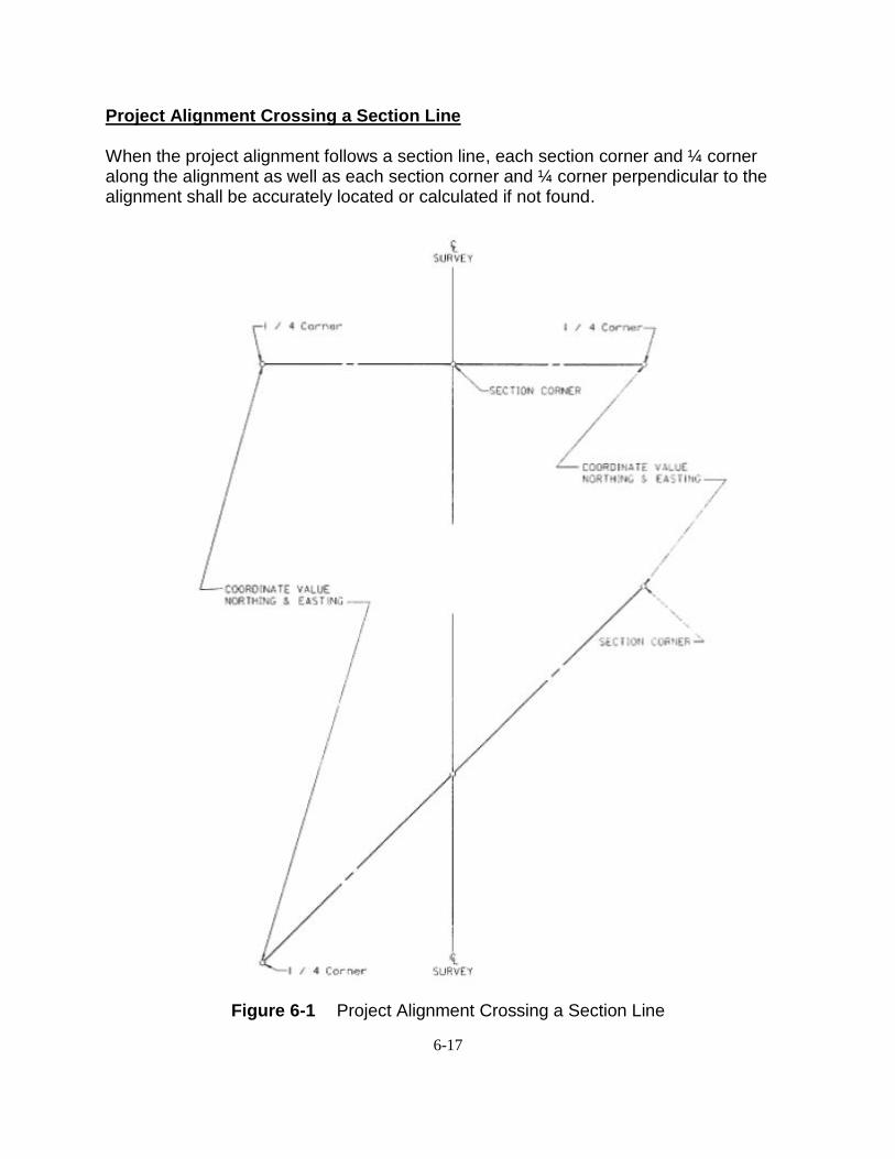
Project Alignment Crossing a Section Line
When the project alignment follows a section line, each section corner and ¼ corner along the alignment as well as each section corner and ¼ corner perpendicular to the alignment shall be accurately located or calculated if not found.
Figure 6-1 Project Alignment Crossing a Section Line
6-18
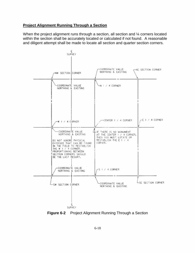
Project Alignment Running Through a Section
When the project alignment runs through a section, all section and ¼ corners located within the section shall be accurately located or calculated if not found. A reasonable and diligent attempt shall be made to locate all section and quarter section corners.
Figure 6-2 Project Alignment Running Through a Section
6-19
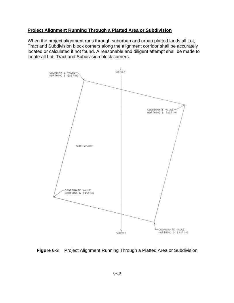
Project Alignment Running Through a Platted Area or Subdivision When the project alignment runs through suburban and urban platted lands all Lot, Tract and Subdivision block corners along the alignment corridor shall be accurately located or calculated if not found. A reasonable and diligent attempt shall be made to locate all Lot, Tract and Subdivision block corners.
Figure 6-3 Project Alignment Running Through a Platted Area or Subdivision
6-20
COLLECTING PLANIMETRIC AND DIGITAL TERRAIN MODEL DATA
A topographic survey is conducted using either GPS RTK, conventional or robotic survey methods. The use of GPS RTK in urban canyons and against or near buildings will not be used. GPS RTK will not consistently produce the accuracies needed for topographic surveys as defined under Topography and Surface General Standard on page 6-24 of this chapter.
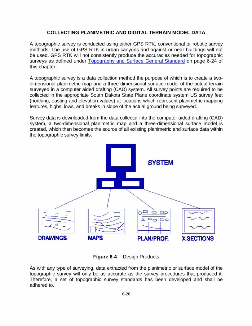
A topographic survey is a data collection method the purpose of which is to create a two-dimensional planimetric map and a three-dimensional surface model of the actual terrain surveyed in a computer aided drafting (CAD) system. All survey points are required to be collected in the appropriate South Dakota State Plane coordinate system US survey feet (northing, easting and elevation values) at locations which represent planimetric mapping features, highs, lows, and breaks in slope of the actual ground being surveyed. Survey data is downloaded from the data collector into the computer aided drafting (CAD) system, a two-dimensional planimetric map and a three-dimensional surface model is created, which then becomes the source of all existing planimetric and surface data within the topographic survey limits.
Figure 6-4 Design Products
As with any type of surveying, data extracted from the planimetric or surface model of the topographic survey will only be as accurate as the survey procedures that produced it. Therefore, a set of topographic survey standards has been developed and shall be adhered to.
6-21
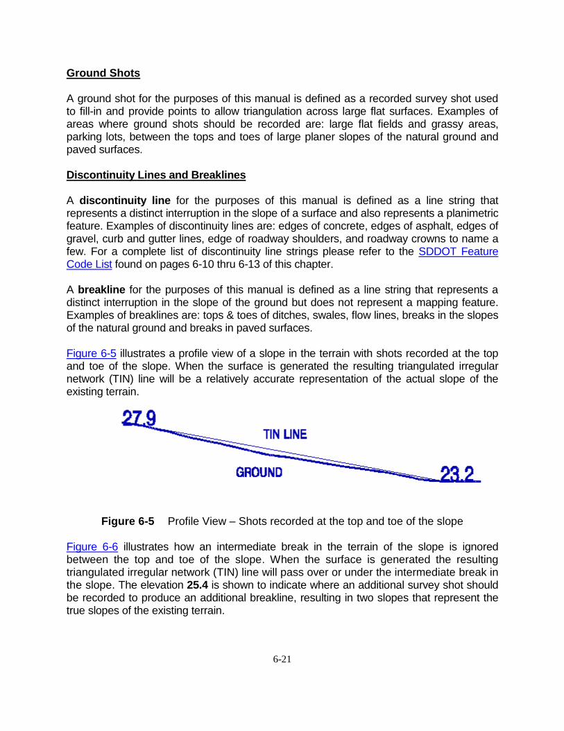
Ground Shots A ground shot for the purposes of this manual is defined as a recorded survey shot used to fill-in and provide points to allow triangulation across large flat surfaces. Examples of areas where ground shots should be recorded are: large flat fields and grassy areas, parking lots, between the tops and toes of large planer slopes of the natural ground and paved surfaces. Discontinuity Lines and Breaklines A discontinuity line for the purposes of this manual is defined as a line string that represents a distinct interruption in the slope of a surface and also represents a planimetric feature. Examples of discontinuity lines are: edges of concrete, edges of asphalt, edges of gravel, curb and gutter lines, edge of roadway shoulders, and roadway crowns to name a few. For a complete list of discontinuity line strings please refer to the SDDOT Feature Code List found on pages 6-10 thru 6-13 of this chapter. A breakline for the purposes of this manual is defined as a line string that represents a distinct interruption in the slope of the ground but does not represent a mapping feature. Examples of breaklines are: tops & toes of ditches, swales, flow lines, breaks in the slopes of the natural ground and breaks in paved surfaces. Figure 6-5 illustrates a profile view of a slope in the terrain with shots recorded at the top and toe of the slope. When the surface is generated the resulting triangulated irregular network (TIN) line will be a relatively accurate representation of the actual slope of the existing terrain.
Figure 6-5 Profile View – Shots recorded at the top and toe of the slope
Figure 6-6 illustrates how an intermediate break in the terrain of the slope is ignored between the top and toe of the slope. When the surface is generated the resulting triangulated irregular network (TIN) line will pass over or under the intermediate break in the slope. The elevation 25.4 is shown to indicate where an additional survey shot should be recorded to produce an additional breakline, resulting in two slopes that represent the true slopes of the existing terrain.
6-22
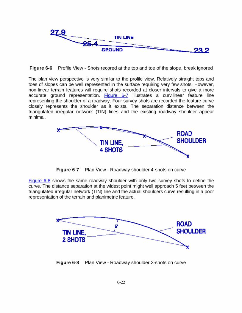
Figure 6-6 Profile View - Shots recored at the top and toe of the slope, break ignored The plan view perspective is very similar to the profile view. Relatively straight tops and toes of slopes can be well represented in the surface requiring very few shots. However, non-linear terrain features will require shots recorded at closer intervals to give a more accurate ground representation. Figure 6-7 illustrates a curvilinear feature line representing the shoulder of a roadway. Four survey shots are recorded the feature curve closely represents the shoulder as it exists. The separation distance between the triangulated irregular network (TIN) lines and the existing roadway shoulder appear minimal.
Figure 6-7 Plan View - Roadway shoulder 4-shots on curve Figure 6-8 shows the same roadway shoulder with only two survey shots to define the curve. The distance separation at the widest point might well approach 5 feet between the triangulated irregular network (TIN) line and the actual shoulders curve resulting in a poor representation of the terrain and planimetric feature.
Figure 6-8 Plan View - Roadway shoulder 2-shots on curve
6-23
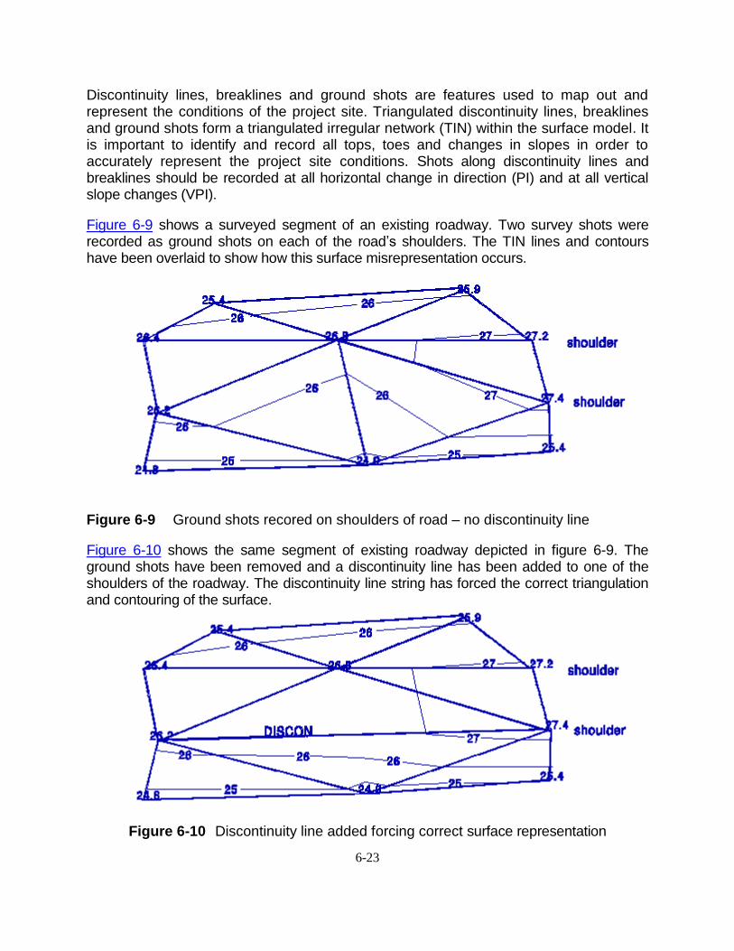
Discontinuity lines, breaklines and ground shots are features used to map out and represent the conditions of the project site. Triangulated discontinuity lines, breaklines and ground shots form a triangulated irregular network (TIN) within the surface model. It is important to identify and record all tops, toes and changes in slopes in order to accurately represent the project site conditions. Shots along discontinuity lines and breaklines should be recorded at all horizontal change in direction (PI) and at all vertical slope changes (VPI).
Figure 6-9 shows a surveyed segment of an existing roadway. Two survey shots were recorded as ground shots on each of the road’s shoulders. The TIN lines and contours have been overlaid to show how this surface misrepresentation occurs.
Figure 6-9 Ground shots recored on shoulders of road – no discontinuity line
Figure 6-10 shows the same segment of existing roadway depicted in figure 6-9. The ground shots have been removed and a discontinuity line has been added to one of the shoulders of the roadway. The discontinuity line string has forced the correct triangulation and contouring of the surface.
Figure 6-10 Discontinuity line added forcing correct surface representation
6-24
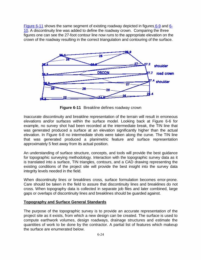
Figure 6-11 shows the same segment of existing roadway depicted in figures 6-9 and 6-10. A discontinuity line was added to define the roadway crown. Comparing the three figures one can see the 27-foot contour line now runs to the appropriate elevation on the crown of the roadway resulting in the correct triangulation and contouring of the surface.
Figure 6-11 Breakline defines roadway crown Inaccurate discontinuity and breakline representation of the terrain will result in erroneous elevations and/or surfaces within the surface model. Looking back at Figure 6-6 for example, no survey shot had been recorded at the intermediate break, the TIN line that was generated produced a surface at an elevation significantly higher than the actual elevation. In Figure 6-8 no intermediate shots were taken along the curve. The TIN line that was generated produced a planimetric feature and surface representation approximately 5 feet away from its actual position.
An understanding of surface structure, concepts, and tools will provide the best guidance for topographic surveying methodology. Interaction with the topographic survey data as it is translated into a surface, TIN triangles, contours, and a CAD drawing representing the existing conditions of the project site will provide the best insight into the survey data integrity levels needed in the field.
When discontinuity lines or breaklines cross, surface formulation becomes error-prone. Care should be taken in the field to assure that discontinuity lines and breaklines do not cross. When topography data is collected in separate job files and later combined, large gaps or overlaps of discontinuity lines and breaklines should be guarded against.
Topography and Surface General Standards
The purpose of the topographic survey is to provide an accurate representation of the project site as it exists, from which a new design can be created. The surface is used to compute earthwork volumes, design roadways, drainage structures and estimate the quantities of work to be done by the contractor. A partial list of features which makeup the surface are enumerated below.
6-25
1. Curb and Gutter - Elevations shall be taken to ±0.03 – 0.04 feet (9-12 mm) on the top of curbs and in the gutter.
2. Misc. Drainage Items - Elevations shall be taken to ±0.03 – 0.04 feet (9-12 mm) on
all catch basins, manholes, top of grates, floor elevations, leaching basins, inlets and outlets, flow lines, culverts, and box culverts.
3. Underground Utilities - Elevations of underground utilities, such as telephone
conduits, gas mains, sewers, etc., shall be taken (some of these elevations may have to be collected at manholes along the utility route).
4. High Water Elevations - Elevations will be taken at rivers, creeks, streams and
sloughs. 5. Wells - Elevations shall be taken on the top of the casing. 6. Intersecting Roads or Streets - The point of intersection, angle of intersection,
planimetric (both above ground and underground), drainage patterns, top of curb and all gutters shall be recorded for 300 feet.
7. Railroad Tracks - Elevations shall be taken to ±0.03 – 0.04 feet (9-12 mm) on all railroad tracks that cross the survey corridor for a distance of 500 feet right and left of the corridor centerline. When the survey parallels the railroad tracks, the survey should be expanded to include the railroad bed.
8. Roadway Pavement - Elevations shall be taken to ±0.03 – 0.04 feet (9-12 mm) on all
pavements. These elevations shall be taken at the crown, breaklines and edge of pavements.
9. Sidewalks - Elevations shall be taken to ±0.03 – 0.04 feet (9-12 mm) on both edges
of all sidewalks.
10. Buildings - In rural areas the location of all buildings within 400 feet of the roadway should be recorded. In urban areas the location of all buildings within 150 feet should be recorded.
11. Driveways - Elevations shall be taken on all driveways. A minimum of three (3) shots
shall be taken to accurately define any curves. 12. Trees and Stumps - In urban areas trees shall be shot individually. In rural areas trees
12” diameter or larger within or near the right-of-way line shall be shot individually. Forests or groves in rural areas shall be shown using the tree belt line code and shot at the beginning, major bends and at the end of the tree grouping.
13. Box Culverts - Elevations shall be taken to ±0.03 – 0.04 feet (9-12 mm) on each
corner of the structure.
6-26
The recommended shot spacing along discontinuity lines, breaklines and to provide proper ground shot coverage is as follows: Urban areas 50-100 feet Suburban areas 50-100 feet Rural areas 100-200 feet Shots shall be taken at closer intervals to define detailed areas and vertical curves. Ground shots, discontinuity lines and breaklines must be extended to sufficiently cover the project limits. The minimum survey limits shall be 300 feet right and left of the corridor centerline. Development in urban areas can sometimes prevent data collection to this width. In developed urban areas, 300 feet right and left of centerline or to building face along the project corridor should provide adequate coverage. All Intersecting streets shall be collected using the same criteria. In hilly areas the ground coverage shall be extended as follows. Toe to bottom 1/3 hill – 300 feet right and left of corridor centerline From bottom 1/3 to 2/3 hill – 600 feet right and left of corridor centerline From 2/3 to top of hill – 900 feet right and left of corridor centerline Note Keeping
The keeping of good survey notes is of the utmost importance because they:
1. present the entire record of a survey 2. may be used by people unfamiliar with the work done on a survey project 3. may be introduced as evidence in future legal action 4. reflect the quality of work done during the course of the survey All too often, survey notes are inadequate as crewmembers get in the habit of recording the minimum amount of information. It is the Survey Crew Chief’s responsibility to exercise the initiative in teaching the other crewmembers the requirements for good note keeping and maintaining a high standard of quality. A few principles that apply to all forms of note keeping are:
1. be complete 2. be concise 3. avoid copying
There can never be too much information in survey notes if it is presented in the proper manner. Notes should be completed while in the field, not later in the office. It is better for a beginning note keeper to get all the information in the notes rather than worry about how easy they are to interpret. As experience is gained efforts should be made to
6-27
keep the notes as brief as possible, while still getting all the information desired, and to keep them arranged in a logical sequence. The following is a list of field notes that should be collected for the noted feature. 1. Fences – Note the fence type, number of barbs (if barbed wire), height and condition. 2. Overhead Utilities – Note each type, number of wires, elevation of lowest wire sag,
owner, and voltage and phase if known. 3. Underground Utilities – Note each type, depth, size of storm sewer pipe, diameter of
cables, owner and condition.
4. Culverts – Note size, type, condition, percent silted and length of flared end section. 5. Railroad Crossing – Note crossing type (encasement, pre-cast concrete plank, wood
plank, creosote plank, etc.) and the condition of the crossing. 6. Buildings – Note the type and owner of the business.
7. Trees and Stumps – Note the type, size, and count. The diameter of trees or stumps shall be measured 2 feet above the ground swell. In the case of stumps less than 2 feet above the ground, no note will be taken.
8. Box Culverts – Note the type, height, width and the condition. 9. Wells – Note the size and casing type. There are many other items not mentioned specifically above. When recording planimetric and surface features, review the Feature Code List (see pages 6-10 thru 6-13) and provide the coordinates, code, and applicable notes. The topography file should show a complete and accurate picture of all features and conditions found within the survey limits.
SURVEY DATA REQUIREMENTS
To standardize and expedite the passage of data to the Office of Road Design, data requirements are herein specified.
File Management
All data relating to surveying field and office work will be stored in the project folder within the appropriate Region folder on the U drive (U:\regionX\prj\cntyPCN#). Do not store survey data on your local drive as this drive is not backed up as often as the U drive, the storage space is smaller than the servers and the information is not readily available to others.
6-28
Data Collector Files
All data collector job files will be saved and will not be edited. The files will be transferred and stored in the csv & jobs folder within the project folder in the appropriate Region folder on the U: drive (U:\regionX\prj\cntyPCN#\csv & jobs). It is important these files be saved in their original unedited format for legal reasons. Exported CSV files will also be saved within the csv & jobs folder.
Topography Data Furnished (.dgn file)
The field topography survey data is downloaded, edited, and processed into a computer aided drafting (CAD) file. The Department of Transportation utilizes three scales when designing projects:
Rural scale 1" = 100' Suburban scale 1" = 50' Urban scale 1" = 20'
The field topography CAD file is stored within the project folder within the appropriate Region folder on the U: drive (U:\regionX\prj\cntyPCN#).
DOT standard naming convention for the topography file is as follows: tPCN#*.dgn
t represents topography and is always lowercase PCN# represents the project control number assigned to the project and is always
uppercase * represents one of the three design file scales and is always lowercase:
r = rural scale s = suburban scale u = urban scale
.dgn represents the file extension for the CAD files. Any additional survey that is needed after the original survey has been processed will need to be merged into the original topographic survey file. Fieldbook Data Furnished (.fwd file)
After downloading, editing and processing all field topography data a fieldbook file (.fwd) will be produced. The fieldbook file contains the edited and processed information that was collected in the field and is stored within the project folder within the appropriate Region folder on the U: drive (U:\regionX\prj\cntyPCN#). There will be only ONE fieldbook file per project except on large projects when the file size becomes so great that it slows processing significantly. Splitting the fieldbook into TWO smaller files may alleviate this issue.
6-29
DOT standard naming convention for the fieldbook file is as follows: PCN#.fwd
PCN# represents the project control number assigned to the project and is always
uppercase .fwd represents the file extension for the fieldbook file If additional survey is collected after the original fieldbook file has been saved a new fieldbook file will need to be created after the field surveys are merged into one fieldbook file. The outdated fieldbook will be overwritten by the new fieldbook using the same file name. Geometry Data Furnished (.alg file)
Through the process of downloading, editing and processing of the field topography data a geometry file (.alg) will be produced. The Geometry file is stored in the project folder in the appropriate Region folder on the U: drive (U:\regionX\prj\cntyPCN#). There will be only ONE geometry file per project. DOT standard naming convention for the geometry file is as follows: PCN#org.alg
PCN# represents the project control number assigned to the project and is always
uppercase org represents the geometry file as original geometry and is always lowercase .alg represents the file extension for the geometry file If additional survey is collected after the original geometry file has been saved a new geometry file will need to be created after the field surveys are merged into one fieldbook file. The outdated geometry file will be overwritten by the new geometry file using the same file name. Surface Data Furnished (.dtm file)
After editing the field topography data a surface model (.dtm) will be produced. The surface model file is stored in the project folder within the appropriate Region folder on the U: drive (U:\regionX\prj\cntyPCN#). There will be only ONE original surface model file per project.
DOT standard naming convention for the surface model file is as follows: PCN#org.dtm
PCN# represents the project control number assigned to the project and is always
uppercase org represents the surface model file as original ground and is always lowercase .dtm represents the file extension for the surface model file

6-30
If additional survey is collected after the original surface model file has been saved a new surface model file will need to be created after the field surveys are merged into one fieldbook file. The outdated surface file will be overwritten by the new surface file using the same file name.
INTERSTATE INTERCHANGE AND HIGHWAY INTERSECTION SURVEYS
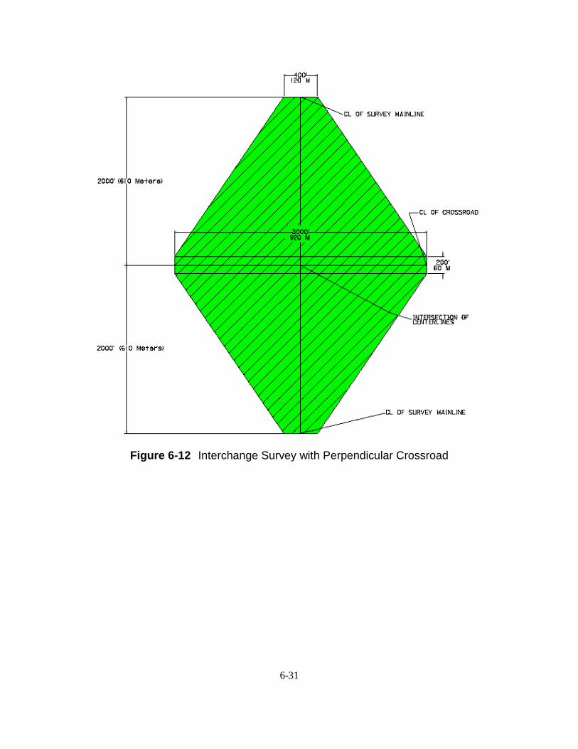
A preliminary survey for an Interchange on the Interstate Highway System is dictated by the alignment of the proposed crossroad provided by the Office of Road Design. The proposed alignment file will usually consist of two points, a beginning and an end. Generally the proposed crossroad alignment will extend 1500 feet in each direction from the intersection with the existing mainline however the distance may vary due to terrain conditions.
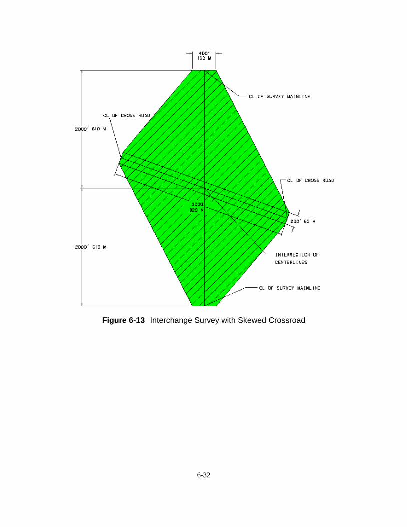
The survey limit widening will begin 2000 feet along the Interstate highway mainline from the proposed crossroad alignment 200 feet each side of the mainline centerline and taper out to the proposed crossroads alignment points, then taper back to 200 feet each side of the mainline centerline 2000 feet past the proposed crossroad alignment. Figure 6-12 and Figure 6-13 on the following pages illustrate the survey limit widening required for the Interstate interchange survey.
6-31
Figure 6-12 Interchange Survey with Perpendicular Crossroad
6-32
Figure 6-13 Interchange Survey with Skewed Crossroad
6-33
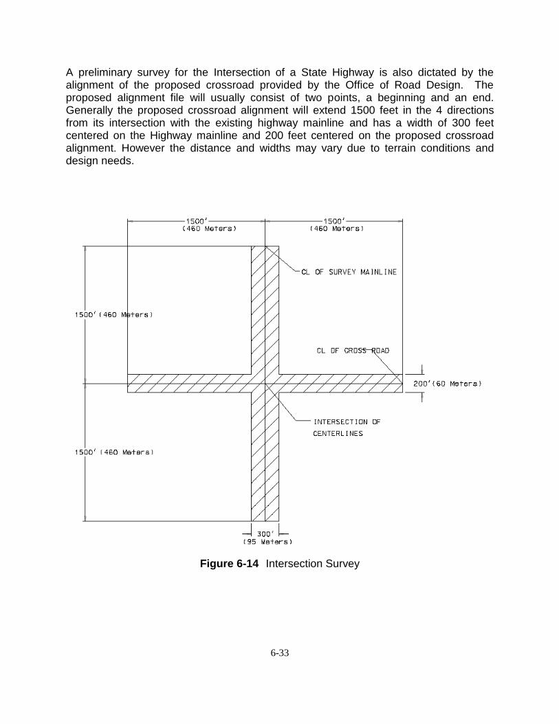
A preliminary survey for the Intersection of a State Highway is also dictated by the alignment of the proposed crossroad provided by the Office of Road Design. The proposed alignment file will usually consist of two points, a beginning and an end. Generally the proposed crossroad alignment will extend 1500 feet in the 4 directions from its intersection with the existing highway mainline and has a width of 300 feet centered on the Highway mainline and 200 feet centered on the proposed crossroad alignment. However the distance and widths may vary due to terrain conditions and design needs.
Figure 6-14 Intersection Survey
6-34
DRAINAGE SURVEYS Drainage surveys are to be conducted in accordance with Section 5.6 of the South Dakota Drainage Manual. A preliminary drainage survey should first identify the locations where drainage structures will be required. If the locations cannot be readily identified in the field, a request for assistance from the Hydraulics Engineer in the Office of Bridge Design may be required. This information may be provided as part of the project scope, or it may be requested by the surveyor when the field survey is initiated. The hydraulics staff will provide a list of the basins over 200 acres and those over 1000 acres. This will identify the survey limits required for each range of drainage basins. General Items The basic information needed for all drainage surveys is as follows:
a) Collect Observed High Water Elevations (OHW) and note date of the high water. It is important that this information be obtained as it can aid the hydraulic engineer in the calibration of the hydraulic model developed to analyze the existing basin and to properly size future structures.
b) For any existing box culvert or large culvert encountered, obtain the flow line (invert
or top of floor) elevation and coordinates of the inlet and outlet ends (see page 6-36). On box culverts the coordinates of all four corners should be recorded. Additional elevations and coordinates at the end of any apron are optional. This data is important for any crossing, but especially important for any culverts that are to be extended or for fish passage considerations.
c) Obtain the lowest elevation of any upstream buildings. d) Obtain data approximately 500 feet to 600 feet both upstream and downstream to
define the channel and any obstructions. Dams often impact the highway crossing location and should always be documented. Provide the spillway crest elevation, width and shape of each dam encountered.
e) Obtain the waterway opening and height at roadway overtopping for any structure
within four miles upstream and downstream of the drainage channel. For bridges, obtain a channel cross section of the bridge opening. For culverts, provide the number, width and height of the culvert(s). If this information is available in some other source such as bridge maintenance inspection files, reference that information. When crossing lake bed areas, the overflow outlet should be located and its elevation established.
f) Complete and submit the Drainage Data Information Sheet found on page 5-38 of
the South Dakota Drainage Manual to the Hydraulics Engineer along with the completed survey files.
6-35
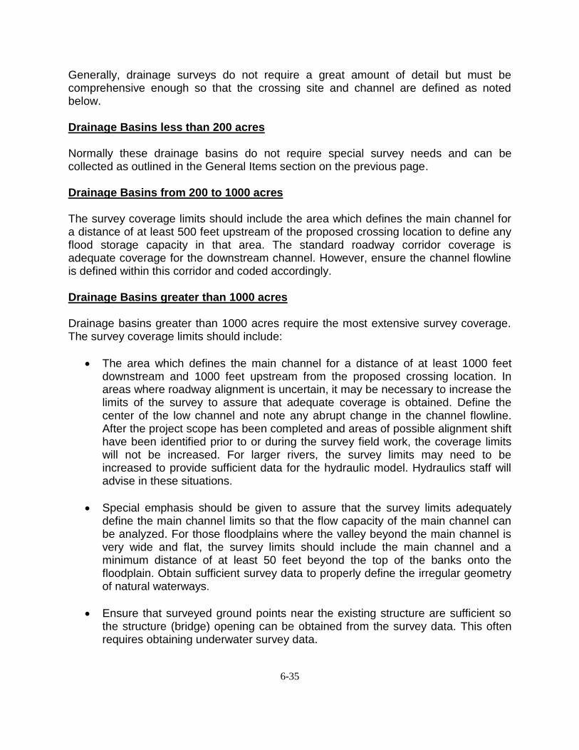
Generally, drainage surveys do not require a great amount of detail but must be comprehensive enough so that the crossing site and channel are defined as noted below. Drainage Basins less than 200 acres Normally these drainage basins do not require special survey needs and can be collected as outlined in the General Items section on the previous page. Drainage Basins from 200 to 1000 acres The survey coverage limits should include the area which defines the main channel for a distance of at least 500 feet upstream of the proposed crossing location to define any flood storage capacity in that area. The standard roadway corridor coverage is adequate coverage for the downstream channel. However, ensure the channel flowline is defined within this corridor and coded accordingly.
Drainage Basins greater than 1000 acres Drainage basins greater than 1000 acres require the most extensive survey coverage. The survey coverage limits should include:
• The area which defines the main channel for a distance of at least 1000 feet downstream and 1000 feet upstream from the proposed crossing location. In areas where roadway alignment is uncertain, it may be necessary to increase the limits of the survey to assure that adequate coverage is obtained. Define the center of the low channel and note any abrupt change in the channel flowline. After the project scope has been completed and areas of possible alignment shift have been identified prior to or during the survey field work, the coverage limits will not be increased. For larger rivers, the survey limits may need to be increased to provide sufficient data for the hydraulic model. Hydraulics staff will advise in these situations.
• Special emphasis should be given to assure that the survey limits adequately define the main channel limits so that the flow capacity of the main channel can be analyzed. For those floodplains where the valley beyond the main channel is very wide and flat, the survey limits should include the main channel and a minimum distance of at least 50 feet beyond the top of the banks onto the floodplain. Obtain sufficient survey data to properly define the irregular geometry of natural waterways.
• Ensure that surveyed ground points near the existing structure are sufficient so the structure (bridge) opening can be obtained from the survey data. This often requires obtaining underwater survey data.
6-36
Any questions concerning survey limits, or special needs for a given site should be directed to the appropriate Hydraulics Engineer prior to commencing the survey.
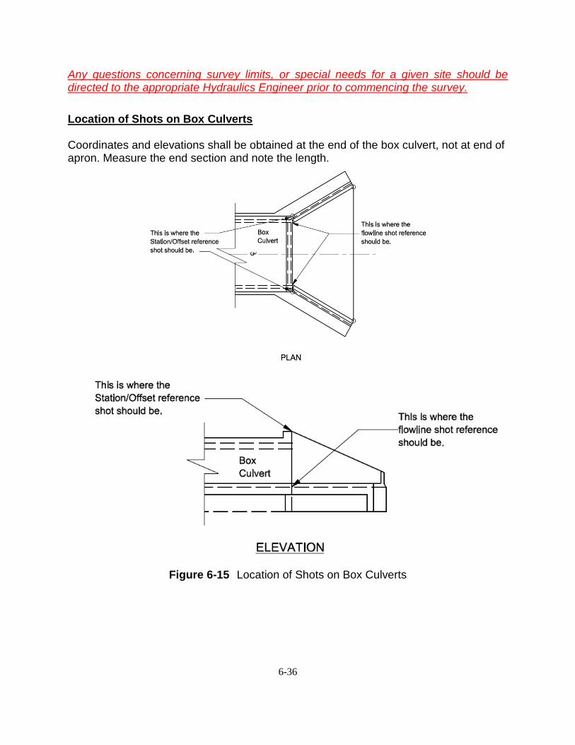
Location of Shots on Box Culverts
Coordinates and elevations shall be obtained at the end of the box culvert, not at end of apron. Measure the end section and note the length.
Figure 6-15 Location of Shots on Box Culverts
6-37
SURVEY REQUIRMENTS FOR 1R, 2R, 3R and 4R PROJECTS
The purpose of this section is to provide direction on collecting the field data needed for the different types of projects.
Survey needs will be determined by Policy Number DOT-P&E-PD-6.0 Definition and Standards for Construction/Reconstruction, Resurfacing, Restoration and Rehabilitation of Highways and Bridges under State Jurisdiction.
1R Projects (Restoration/Preservation)
The purpose of a 1R project is to preserve the existing pavement layers and structures. Surveys requirements for 1R projects will be minimal. The auto level and tape cross section method may be used if approved ahead of time by the Designer requesting the survey data. The following information will need to be gathered in order to properly design the project.
a) Surfacing width and cross slope information at ¼ mile intervals b) Approach surfacing c) Areas of extra width (Mailbox turnout, bus turnarounds, etc.)
2R Projects (Resurfacing and Restoration)
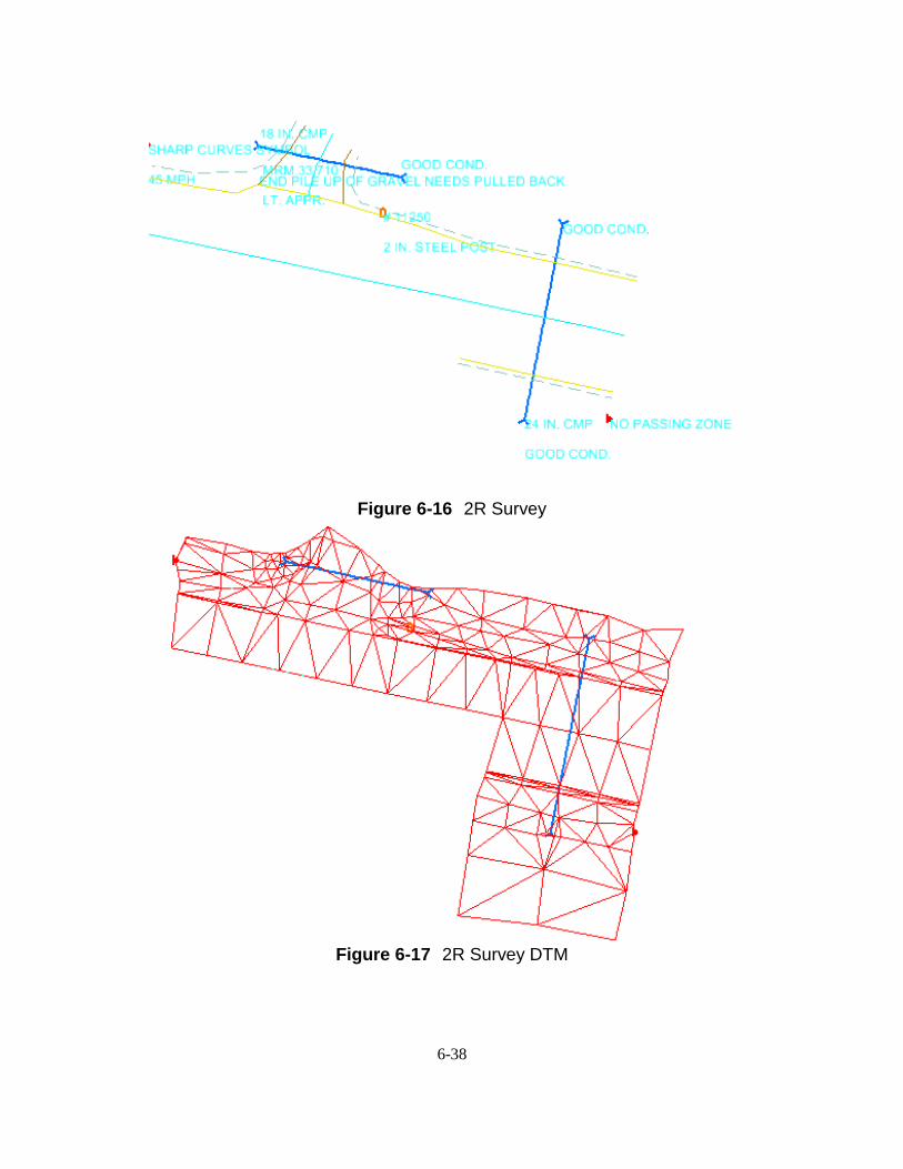
The purpose of a 2R project is to extend the serviceability of the existing roadway pavement and structures to meet the functionality of the highway facility. Survey requirements for 2R projects are the same as the preliminary survey as outlined in section Collecting Planimetric and Digital Terrain Model Data on pages 6-20 to 6-27 of this chapter but, only at specified location. The data will be collected in the appropriate State Plane Coordinate System and processed through the CAD system to produce a fieldbook file (.fwd), alignment file (.alg), DTM file (.dtm), and a design file (.dgn); as outlined in Survey Data Requirements on page 6-27 of this Chapter. The information gathered should be similar to the information in Figure 6-16 and 6-17 on the following page. Segments of the road will be surveyed from right of way line to right of way line, small individual Digital Terrain Models (DTM) will be created at specific locations that allow the design engineer to cut cross-sections where needed. Survey data will be gathered at the following locations to properly design the project. a) Surfacing width and cross slope information at ¼ mile intervals b) Crossing culvert pipes c) Beginning, middle and end of guardrails d) Approach and approach pipe e) Areas of extra width (Mailbox turnouts, bus turnarounds, etc.)
6-38
Figure 6-16 2R Survey
Figure 6-17 2R Survey DTM
6-39
3R Projects (Resurfacing, Restoration, or Rehabilitation)
The purpose of a 3R project is to preserve and extend the life of existing highways and structures while enhancing highway safety. Safety enhancement is an essential consideration, and 3R projects are to be developed and completed in a manner that considers and includes appropriate safety improvements. These 3R standards may be utilized on non-Interstate Systems passing through cities, towns and urban areas. Survey requirements for 3R projects are the same as the preliminary survey in section Collecting Planimetric and Digital Terrain Model Data as outlined on page 6-20 to 6-27 of this chapter. The data will be collected in the appropriate State Plane Coordinate System and processed through the CAD system to produce a fieldbook file (.fwd), alignment file (.alg), DTM file (.dtm), and a design file (.dgn); as outlined in Survey Data Requirements on page 6-27 of this Chapter. Survey data gathered will be the same as the preliminary survey. The following information will need to be gathered in order to properly design the project.
a) Topographic surveys at specific locations (pipe repair, inslope flattening, turn-
lane addition/intersection work, etc.) extending 300 feet each side of centerline.
b) Intersection roads extending 300 feet each side of centerline of the intersecting roads.
c) Other items may be addressed in the scope that will require additional survey. 4R Projects (Complete Reconstruction)
The purpose of a 4R project is to completely reconstruct the existing highway infrastructure. Survey requirements for 4R projects are the same as the preliminary survey in section Collecting Planimetric and Digital Terrain Model Data as outlined on page 6-20 to 6-27 of this chapter. The data will be collected in the appropriate State Plane Coordinate System and processed through the CAD system to produce a fieldbook file (.fwd), alignment file (.alg), DTM file (.dtm), and a design file (.dgn); as outlined in Survey Data Requirements on page 6-27 of this chapter.
Survey data gathered will be the same as the preliminary survey. The following information will need to be gathered in order to properly design the project.
a) Full topographic surveys extending 300 feet each side of centerline. b) Intersecting roads extending 300 feet each side of centerline of the intersecting
roads. c) Other items may be addressed in the scope that will require additional survey. d) Additionally the survey may include areas of proposed new alignments.
SUBSURFACE UTILITY/UTILITY SURVEYS
Subsurface utility surveys are becoming more important as the amount of underground utilities continues to increase. The utilities need to be accurately mapped in three-dimension to ensure that they will be avoided during construction or moved prior to construction.
6-40
If the utility survey is performed by DOT personal a non-excavation locate request called an appointment planning request shall be executed through the SD One-Call center. The appointment planning ticket will be called in by calling 811 five days prior to any field work performed. Maps provided by the locator and or owner of the utilities may and should be used to help interpret the SD One Call markings in order to accurately map the utilities. Additional utility maps may be available and are located in the project development folder under U:\pd\cntyPCN#\Utilities. Old DOT construction plans may also be used to ensure storm sewers are accurately mapped.
Subsurface utility engineering (SUE) surveys may be performed by contracted SUE utility mapping consultants. These completed surveys include all underground private and public utilities, all existing storm sewer (including drop inlets, manholes, inverts, photography, etc.), all above ground and overhead public utilities (including street lights, traffic signals, controller cabinets, etc.). Project deliverables from the SUE consultant to the DOT include a MicroStation .dgn file, field notes, a drainage database, images of all drainage structures; and a sealed and signed hard copy of utility plan sheets. The MicroStation .dgn file will be stored in the appropriate road design folder under U:\rd\prj\cntyPCN#. The remaining SUE deliverables will be stored in the road design folder under U:\rd\prj\cntyPCN#\utilities\SUE\.
Sometimes the utilities surveyed by the SUE consultant need to be extended due to the expansion of the project limits. If extra utilities need to be surveyed by DOT personnel, the survey must be committed into a separate .dgn file; which will then be added to the file submitted by the SUE consultant. A review of the SUE survey and the preliminary design may indicate a utility conflict that will require further exploration to determine the depth of the existing utility in a specific area.
1. The utilities will be physically exposed by the SUE consultant using a vac-truck. 2. The SUE consultant will contact the appropriate Area Surveyor to survey the location
of the test holes. 3. The surveyor will survey the locations using the TSTSUE code and record the
following information provided on the test hole flag. a. test hole number (as the point number) b. the cut (depth to utility) c. the utility owner d. select the type of utility from the attributes pulldown
4. Update the preliminary survey FWD (PCN#.fwd) file with the test hole data 5. Update the preliminary survey ALG (PCN#org.alg) file with the test hole data 6. Update the preliminary survey DTM (PCN#org.dtm) file with the test hole data 7. Recommit the graphics to update the preliminary survey DGN (tPCN#*.dgn) file with
the test hole data
Radon Gas Warning: Utility Vaults may be filled with Radon gas an invisible and poisonous gas. Breathing this gas could be fatal if vault lids are open and the air within them is inhaled please use extreme caution when surveying these utility vaults

6-41
BRIDGE DECK SURVEYS The Bridge Maintenance Engineer will send the Area Office a layout of each structure scheduled for bridge deck overlay. The layout will indicate the specific data that must be collected for that structure during the survey. DO NOT PROCEED WITH A BRIDGE DECK SURVEY UNTIL YOU HAVE RECEIVED A STRUCTURE LAYOUT OR
CONTACTED THE BRIDGE MAINTENANCE ENGINEER.
ADA SURVEYS
It is expected that there will be increased impacts to ROW, Utilities, etc. based on applying current and proposed ADA requirements.
Therefore, surveys for resurfacing and stand-alone lighting, signal, or signing projects need to be obtained earlier so the design process can begin a minimum of 2 years prior to the proposed letting date of the project. In some cases a more detailed survey will be needed for those type of projects listed above.
During the scope process for all projects, the type and amount of survey shall be noted. In some cases the designer may need to perform a field inspection to determine what locations need a detailed survey so that the designer can check if the current location meets ADA requirements and/or use the survey data to determine impacts to ROW, utilities, etc. during design. Limits of ADA surveys at intersections typically extend 50 feet to 100 feet beyond the PC and PT of the intersection fillets. Before preforming an ADA survey contact the designer or responsible manager to determine the limits of the survey. When ground shots and topography features are collected, the survey should include adequate coverage to detail the sidewalk and ramp widths, cross slopes, longitudinal grades, landing size, vertical grade breaks, steps, thresholds and all ADA related items located within and near the pedestrian access route along the highway ROW. Total stations and or robotic total stations will be used on all ADA projects. Elevations shall be collected to ±0.03 – 0.04 feet (9-12 mm) accuracy on all ADA related features included in the Digital Terrain Model (DTM). GPS RTK positions using a single base station does not provide sufficient accuracy and will not be used for this type of survey. For critical tie in points such as thresholds, ramps, steps, landings etc., elevations should be verified by the use of an auto level unless originally collected by a robotic total station. Note Keeping
The keeping of good ADA survey notes is of utmost importance because they:
6-42
1. present the entire record of the survey 2. may be used by people unfamiliar with the work done on a survey project 3. reflect the quality of work done during the course of the survey A few principles that apply to all forms of note keeping are:
4. be complete 5. be concise 6. avoid copying as much a possible
Keep notes as brief as possible, while still getting all the information desired, and to keep them arranged in a logical sequence. Following is a list of a few examples of field notes that should be recorded when performing ADA surveys. 1. Thresholds – Note whether the door opens in or out and which side the door is hinged
on while facing the door. 2. Traffic Signal poles – Note if push button is present.
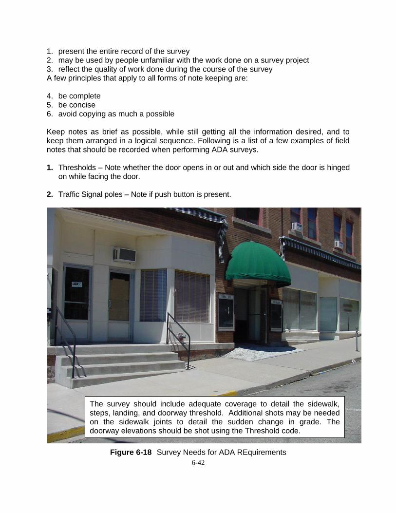
Figure 6-18 Survey Needs for ADA REquirements
The survey should include adequate coverage to detail the sidewalk, steps, landing, and doorway threshold. Additional shots may be needed on the sidewalk joints to detail the sudden change in grade. The doorway elevations should be shot using the Threshold code.
6-43
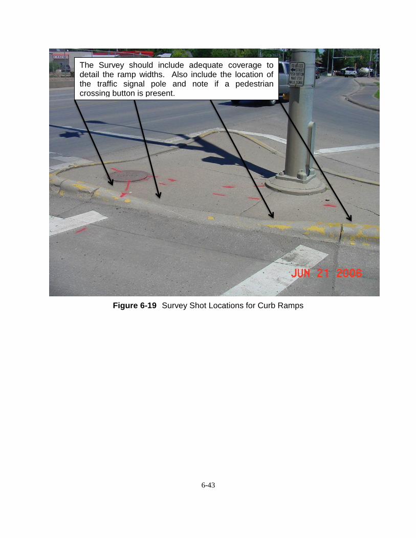
Figure 6-19 Survey Shot Locations for Curb Ramps
The Survey should include adequate coverage to detail the ramp widths. Also include the location of the traffic signal pole and note if a pedestrian crossing button is present.


![· 2018. 1. 19. · *yrm ]-t 4r (t +pvu z* "q \y#4r (j6b+/.x*(q 0l [v 4r (](https://img.pdfslide.us/doc/110x75/6047699cd990367e57623af2/-2018-1-19-yrm-t-4r-t-pvu-z-q-y4r-j6bxq-0l-v-4r-.jpg)