Embed Size (px)
Citation preview
S. Arsoy CHAPTER 6
132132
CHAPTER 6 – NUMERICAL INVESTIGATIONS OF INTEGRAL
BRIDGE/SOIL INTERACTIONS
6.1. Introduction
Integral bridges are subjected to complex soil/structure interactions. A thorough
understanding of these interactions is needed to provide a basis for expanding the current
limits on the lengths of integral abutment bridges.
This chapter presents the findings of series of finite element analyses that were
performed to investigate the significance of the interactions among the abutment, the
approach fill, the foundation soil, and the piles. The effect of the approach fill on the
stresses in the piles supporting the abutment, and the effects of the type of abutment
(fully versus semi-integral) were examined in these analyses.
The possibility of using simple procedures for design of the piles was investigated.
Discussions of the results of the analyses and recommendations for future research are
presented at the end of this chapter.
S. Arsoy CHAPTER 6
133133
6.2. Objectives of Numerical Analysis
The objectives of the research include investigation of the:
• Effect of the stiffness of the foundation soil on pile stresses,
• Effect of fully integral abutments on pile stresses,
• Effect of semi-integral abutments on pile stresses, and
• Possibility to develop a simplified method for design of piles supporting integral
abutment bridges.
6.3. Expected Soil/Abutment/Pile Interactions
As the superstructure expands toward the approach fill, a series of interactions takes
place between the following components of the bridge and its foundation:
• Abutment/approach fill,
• Approach fill/foundation soil,
• Foundation soil/pile, and
• Pile/abutment.
These interactions should be more fully understood in order to expand the current limits
on the lengths of integral abutment bridges.
Abutment/approach fill interactions result in changes in the earth pressures acting on
the bridge abutment. The magnitude and the mode of the abutment movement are
primary factors that control the earth pressures. Earth pressures decrease as the bridge
contracts, and increase when the bridge expands.
As the approach fill is pushed by the abutment, it tends to move the foundation soil
in the same direction. This is beneficial as far as the pile stresses are concerned because
the foundation soil acts as if it were softer because it is moving in the same direction as
the piles. This results in lower stresses in the piles.
S. Arsoy CHAPTER 6
134134
The type of foundation soil is important in determining the pile stresses. For
conditions where a given amount of displacement is imposed at the tops of the piles, as is
the case for piles supporting integral bridges, softer soils result in lower pile stresses than
do stiffer soils. A computer program such as LPILE is useful for assessing the stresses
resulting from imposed displacements.
The interactions between the abutment and the piles that support it also have an
important influence on the pile stresses. Experiments were conducted to investigate this
issue. The findings of the experimental program were presented in Chapter 5.
A combination of these factors result in interactions among the abutment, the
approach fill, the foundation soil and the piles. These interactions can be modeled by
conducting finite element studies. The results of the finite element analyses provide a
basis for improved understanding of the behavior of integral bridges and their
foundation.
6.4. Software Selection
The interactions between the bridge system and the approach system would be best
modeled by a finite element program capable of solving three-dimensional problems.
However, 3D finite element analyses would require more time and effort than was
possible within the scope of this study. To give some understanding of the complex
interactions described in the previous paragraphs, it was decided to use the computer
programs SAGE and LPILE for this investigation. Description of the capabilities of
SAGE and LPILE are presented below.
6.4.1. SAGE
Finite element analyses were performed using the finite element program SAGE 2.03
(Static Analysis of Geotechnical Engineering Problems) developed at Virginia Tech.
SAGE is capable of analyzing 2D plane strain soil-structure interaction problems.
Newton-Raphson iteration is used to solve the non-linear equations.
S. Arsoy CHAPTER 6
135135
Element types include triangular, quadrilateral, beam-bar, Wilson, and zero-thickness
interface elements. Soil behavior can be modeled by choosing from ten material models,
including; Mohr-Coulomb, Drucker-Prager, Hyperbolic, and Cam Clay (Bentler et al.,
1999).
6.4.2. LPILE
LPILE is a program developed by Ensoft, Inc. of Austin, TX for analyzing the
behavior of piles under lateral loading. The program is based on the finite difference
method, and approximates 3D soil/pile interaction through the use of nonlinear p-y
curves.
Deflection, shear, moment, and soil response along the pile are computed. The
boundary conditions at the pile head can be specified in terms of shear, moment,
displacement, and rotational stiffness.
6.5. Bridge Geometry
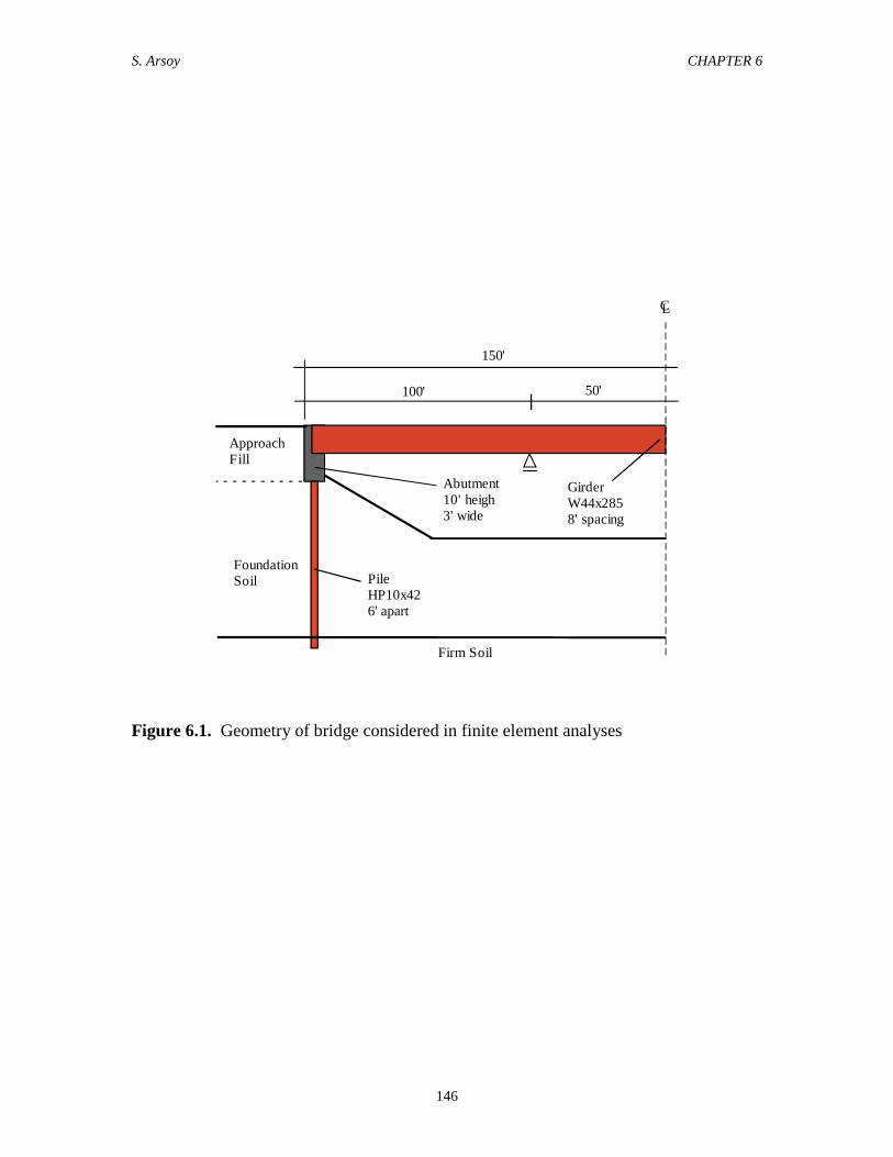
A 300-ft long integral abutment bridge was selected for the parametric analyses. It
was assumed that the bridge consists of W44x285 steel girders spaced 8 feet apart, with a
10-inch thick concrete deck, resting on 10-ft high 3.0-ft thick abutments, which are
supported by HP10x42 steel piles, spaced 6 feet apart, as shown in Figure 6.1.
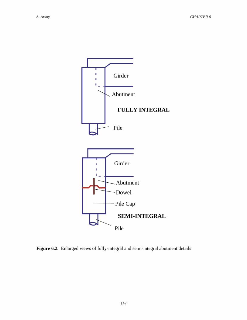
Two abutment types were considered: fully integral and semi-integral. Enlarged
views of these abutments are depicted in Figure 6.2. The semi-integral abutment is
similar to fully integral abutment, except for a lateral joint in the middle of the abutment.
A dowel passes through this joint to prevent shear displacements between the top and
bottom sections of the abutment.
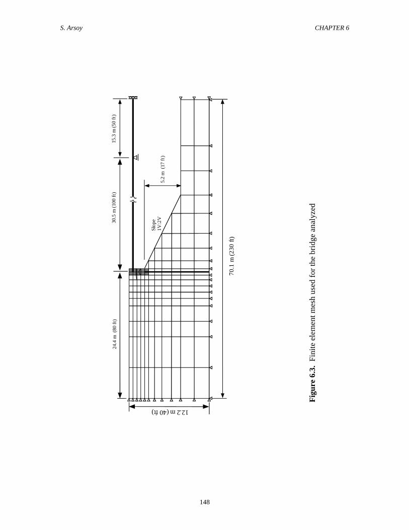
The bridge was modeled as a plain strain problem, with symmetry around the
centerline of the bridge. The finite element mesh used in the analyses is shown in Figure
6.3. Both the fully integral and the semi-integral abutments were modeled using the same
mesh. As can be seen in Figure 6.3, the mesh is finer around the abutment, and is coarser
S. Arsoy CHAPTER 6
136136
near the boundaries. Zero-thickness interface elements were used between the approach
fill and the abutments.
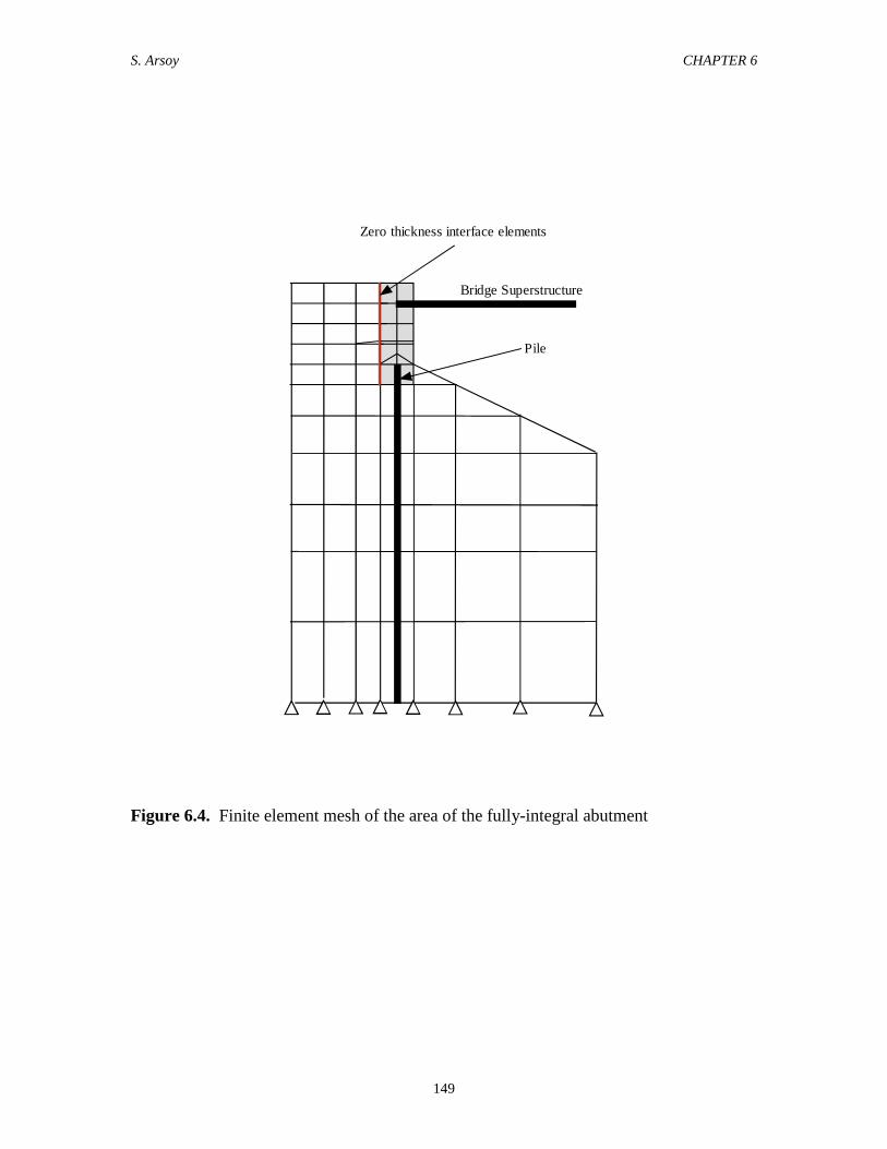
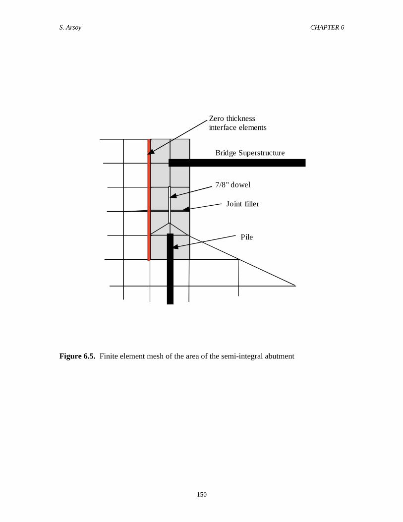
Sections of the finite element mesh around the fully integral abutment and the semi-
integral abutment are shown in large scale in Figures 6.4 and 6.5, respectively. The
lateral joint in the semi-integral abutment was modeled by quadrilateral elements and
beam-bar elements as shown in Figure 6.5.
6.6. Material Properties
Different types of models of nonlinear soil behavior are used in SAGE and LPILE.
The parameters used in these analyses were obtained from published literature (Duncan et
al., 1980, Reese and Wang, 1997).
6.6.1. SAGE
The bridge superstructure, the piles and the dowels of the semi-integral abutments
were modeled as beam-bar elements with linear stress-strain properties. The abutment
and the joint-filler in the semi-integral abutment were modeled using four-node
quadrilateral elements with linear stress-strain properties. The approach fill and the
foundation soil were modeled using four-node quadrilateral and three-node triangular
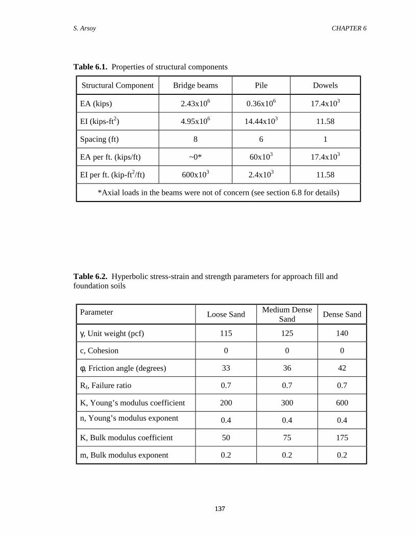
elements with hyperbolic material properties. Table 6.1 and 6.2. summarize the material
properties used in the analyses. The hyperbolic soil parameters representing dense to
loose sand were selected from Duncan et al. (1980).
The behavior of the joint-filler was modeled by setting the values of modulus for
these elements approximately equal to zero so that it does not contribute to the shear, and
all the shear force is absorbed by the dowels.
6.6.2. LPILE
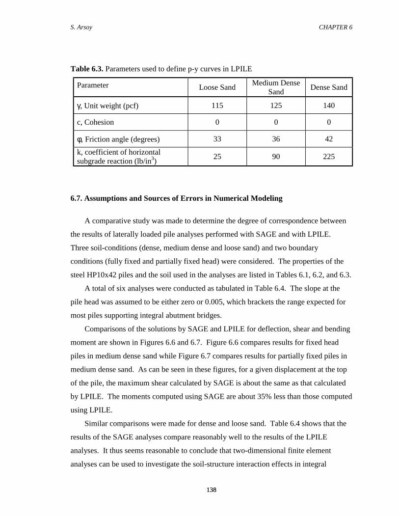
Table 6.3 summarizes the soil parameters used in LPILE. These values were
obtained from the program manual (Reese and Wang, 1997). The soil parameters shown
in Table 6.3 were used by LPILE to generate the p-y curves used in the analyses.
S. Arsoy CHAPTER 6
137137
Table 6.1. Properties of structural components
Structural Component Bridge beams Pile Dowels
EA (kips) 2.43x10⁶ 0.36x10⁶ 17.4x10³
EI (kips-ft2) 4.95x10⁶ 14.44x10³ 11.58
Spacing (ft) 8 6 1
EA per ft. (kips/ft) ~0* 60x103 17.4x10³
EI per ft. (kip-ft2/ft) 600x103 2.4x10³ 11.58
*Axial loads in the beams were not of concern (see section 6.8 for details)
Table 6.2. Hyperbolic stress-strain and strength parameters for approach fill andfoundation soils
Parameter Loose Sand Medium DenseSand Dense Sand
γ, Unit weight (pcf) 115 125 140
c, Cohesion 0 0 0
φ, Friction angle (degrees) 33 36 42
Rf, Failure ratio 0.7 0.7 0.7
K, Young’s modulus coefficient 200 300 600
n, Young’s modulus exponent 0.4 0.4 0.4
K, Bulk modulus coefficient 50 75 175
m, Bulk modulus exponent 0.2 0.2 0.2
S. Arsoy CHAPTER 6
138138
Table 6.3. Parameters used to define p-y curves in LPILE
Parameter Loose Sand Medium DenseSand Dense Sand
γ, Unit weight (pcf) 115 125 140
c, Cohesion 0 0 0
φ, Friction angle (degrees) 33 36 42
k, coefficient of horizontalsubgrade reaction (lb/in3) 25 90 225
6.7. Assumptions and Sources of Errors in Numerical Modeling
A comparative study was made to determine the degree of correspondence between
the results of laterally loaded pile analyses performed with SAGE and with LPILE.
Three soil-conditions (dense, medium dense and loose sand) and two boundary
conditions (fully fixed and partially fixed head) were considered. The properties of the
steel HP10x42 piles and the soil used in the analyses are listed in Tables 6.1, 6.2, and 6.3.
A total of six analyses were conducted as tabulated in Table 6.4. The slope at the
pile head was assumed to be either zero or 0.005, which brackets the range expected for
most piles supporting integral abutment bridges.
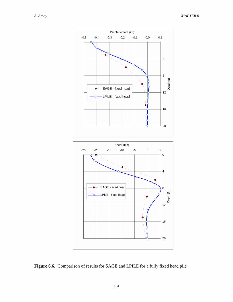
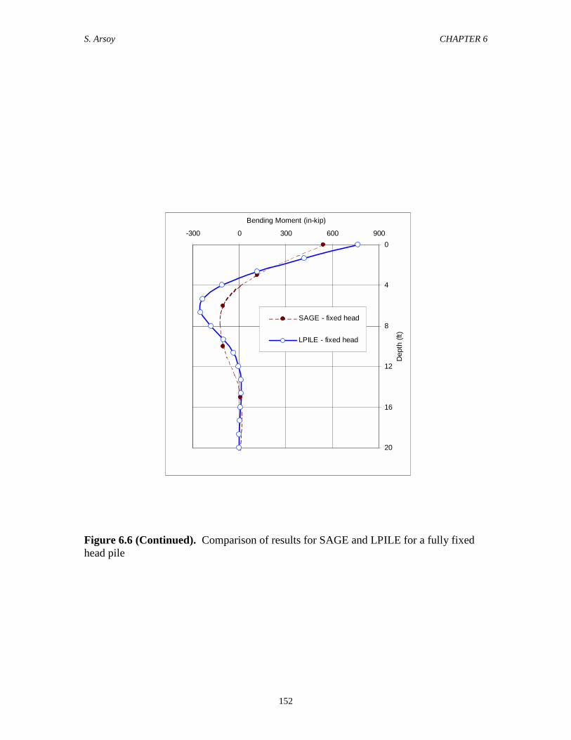
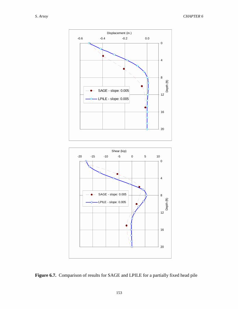
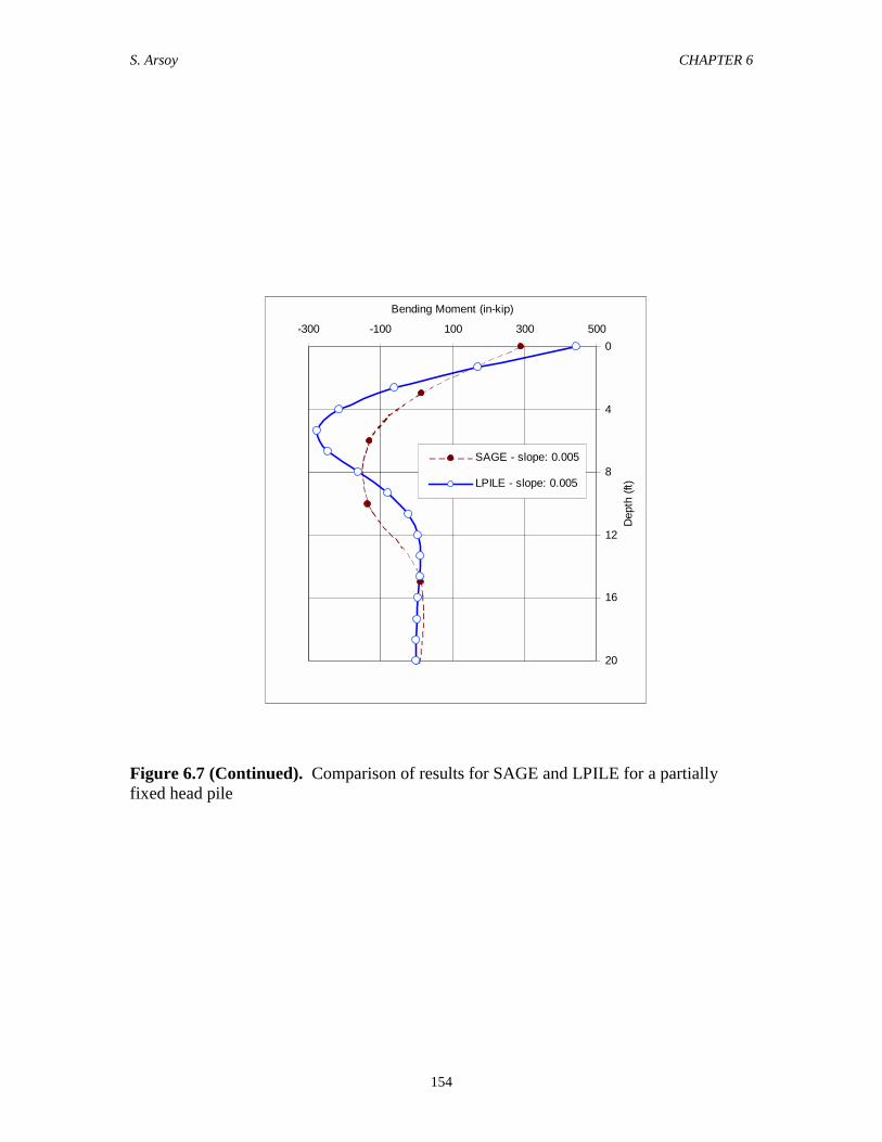
Comparisons of the solutions by SAGE and LPILE for deflection, shear and bending
moment are shown in Figures 6.6 and 6.7. Figure 6.6 compares results for fixed head
piles in medium dense sand while Figure 6.7 compares results for partially fixed piles in
medium dense sand. As can be seen in these figures, for a given displacement at the top
of the pile, the maximum shear calculated by SAGE is about the same as that calculated
by LPILE. The moments computed using SAGE are about 35% less than those computed
using LPILE.
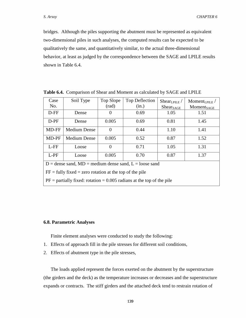
Similar comparisons were made for dense and loose sand. Table 6.4 shows that the
results of the SAGE analyses compare reasonably well to the results of the LPILE
analyses. It thus seems reasonable to conclude that two-dimensional finite element
analyses can be used to investigate the soil-structure interaction effects in integral
S. Arsoy CHAPTER 6
139139
bridges. Although the piles supporting the abutment must be represented as equivalent
two-dimensional piles in such analyses, the computed results can be expected to be
qualitatively the same, and quantitatively similar, to the actual three-dimensional
behavior, at least as judged by the correspondence between the SAGE and LPILE results
shown in Table 6.4.
Table 6.4. Comparison of Shear and Moment as calculated by SAGE and LPILE
CaseNo.
Soil Type Top Slope(rad)
Top Deflection(in.)
ShearLPILE /ShearSAGE
MomentLPILE /MomentSAGE
D-FF Dense 0 0.69 1.05 1.51
D-PF Dense 0.005 0.69 0.81 1.45
MD-FF Medium Dense 0 0.44 1.10 1.41
MD-PF Medium Dense 0.005 0.52 0.87 1.52
L-FF Loose 0 0.71 1.05 1.31
L-PF Loose 0.005 0.70 0.87 1.37
D = dense sand, MD = medium dense sand, L = loose sand
FF = fully fixed = zero rotation at the top of the pile
PF = partially fixed: rotation = 0.005 radians at the top of the pile
6.8. Parametric Analyses
Finite element analyses were conducted to study the following:
1. Effects of approach fill in the pile stresses for different soil conditions,
2. Effects of abutment type in the pile stresses,
The loads applied represent the forces exerted on the abutment by the superstructure
(the girders and the deck) as the temperature increases or decreases and the superstructure
expands or contracts. The stiff girders and the attached deck tend to restrain rotation of
S. Arsoy CHAPTER 6
140140
the abutment, and including the flexural stiffness (EI) of the superstructure in the
analyses models this important aspect of the structural behavior. However, because it
was more convenient to perform the analyses by applying forces rather than
displacements, the axial stiffness (EA) of the girders and the bridge deck were set equal
(approximately) to zero. The axial forces were applied to the abutment along the neutral
axis of the bridge girders.
The characteristics of the finite element model and results are thus:
• The applied force corresponds to the axial forces exerted on the abutment by the
superstructure as temperatures increase or decrease,
• The resulting displacements and rotations of the abutment correspond to the actual
displacements and rotations due to temperature increase and decrease, and
• The forces induced in the abutment, the approach fill, the foundation piles and the
foundation soils show how the loads are carried by increased earth pressures in the
approach fill and increased shear forces on the foundation piles.
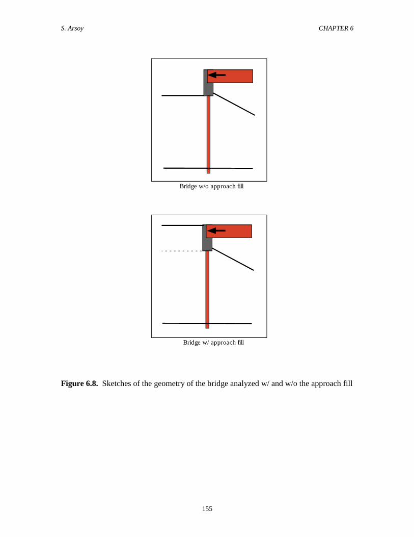
6.8.1. Effects of Approach Fill
The effects of the approach fill on pile stresses were studied by conducting two sets
of finite element analyses. The first set of analyses investigated the pile stresses with no
approach fill. The second set of analyses investigated the pile stresses with an approach
fill. Figure 6.8 shows the cross sections used in these analyses. Lateral forces were
applied through the bridge beams such that the displacement at the pile head was the
same for both sets of analyses. Any difference in the pile stresses was thus due to the
approach fill.
The results of these analyses indicate that the approach fill significantly reduces the
pile stresses. This beneficial reduction in the stresses occurs because the approach fill
drags the foundation soil as it moves, resulting in less resistance of the foundation soil
against the pile displacements. In other words, the foundation soil acts as if it were softer
when the approach fill is in place. It would therefore be excessively conservative to

S. Arsoy CHAPTER 6
141141
perform analyses of the lateral loads on the foundation piles without recognizing this
effect.
Reductions in the maximum shear due to approach fill were calculated for three sand
densities and were tabulated in Table 6.5. Reductions in shear are significant, ranging
from 40% for loose sand to 64% for dense sand. The computed values of slope at the pile
head are also shown in this table. It can be seen that the slope of the pile head increases
as the foundation soil gets more dense. It appears that this occurs because the dense sand
offers greater resistance to lateral displacement of the piles, and more pile head rotation is
required to achieve the same pile head displacement.
Additional finite element analyses were conducted to compare the effects of bridge
expansion and contraction on pile stresses. Lateral forces were applied to pull the
abutment away from the approach fill, such that the pile head displaced about 0.68
inches. The foundation soil was assigned the properties of medium dense sand.
These analyses indicated a slightly smaller beneficial effect of the approach fill for
the case where the bridge contracted. The reduction in the shear due to the presence of
approach fill was 47% in this case, as compared to 51% in the case of expansion. The
stresses in the pile were found to be about 5% higher for 0.68 inch movement of pile head
away from the approach fill than for 0.68 inch movement of pile head towards the
approach fill.
In conclusion, finite element analyses indicate that the presence of the approach fill
significantly reduces the stresses in piles supporting integral bridges. Pile stresses are
slightly higher for the contraction mode than for the expansion mode.
6.8.2. Effects of abutment type: fully vs. semi-integral
Finite element analyses were conducted to compare the behavior of fully integral and
semi-integral abutments. The foundation soil was assigned the properties of medium
dense sand.
Loads were applied through the bridge beams to induce 2 inches of displacement
towards the approach fill in both cases.

S. Arsoy CHAPTER 6
142142
Table 6.5. Reductions in maximum pile stresses due to approach fill
Foundation Soil Displacement atpile head (in.)
Slope at pilehead** (rad.) Reduction in Shear*
Dense Sand 0.70 0.0065 64%
Medium Dense Sand 0.68 0.0056 51%
Loose Sand 0.70 0.0054 40%
* As compared to the analyses with no approach fill
** For cases with approach fill.
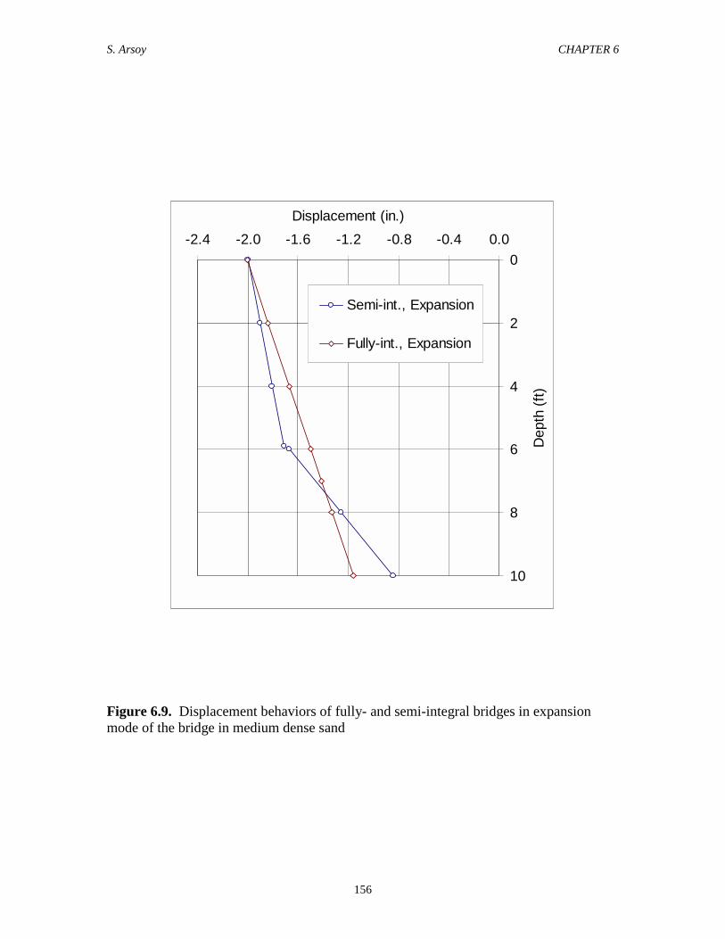
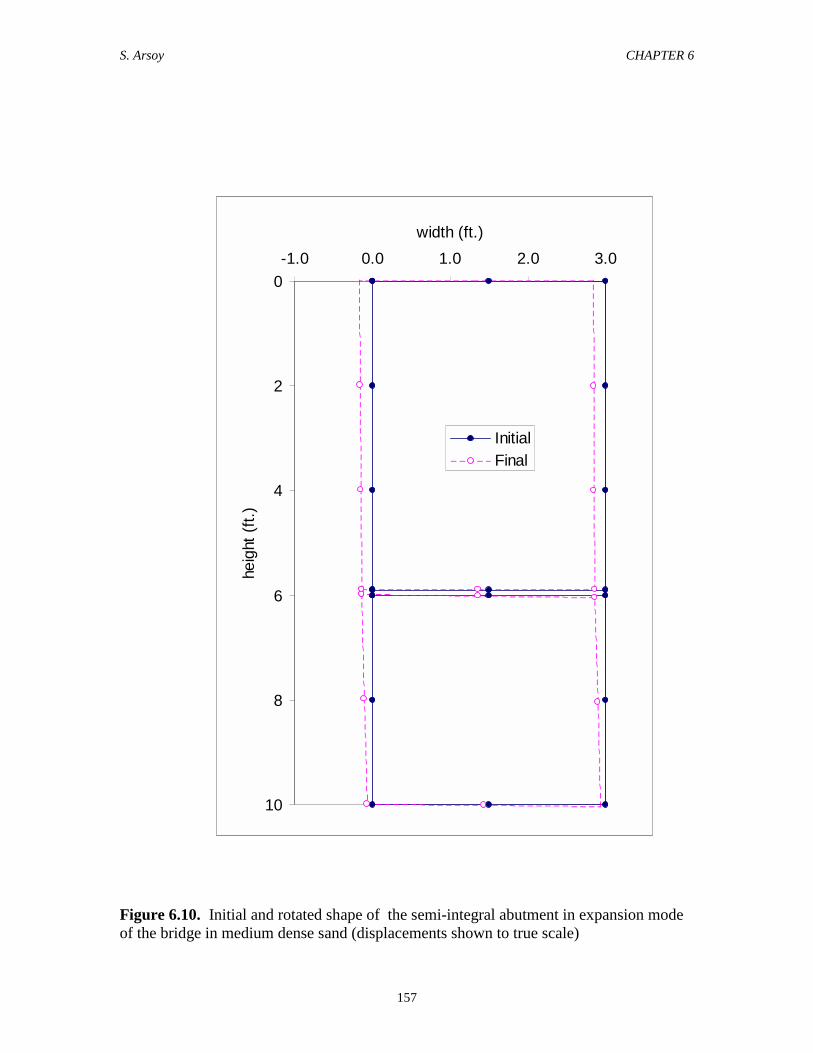
Figure 6.9 shows the displaced positions of the integral and the semi-integral
abutments in medium dense sand. The initial and the displaced geometry of the semi-
integral abutment are shown in Figure 6.10. As can be seen in Figure 6.9, the bottom of
the semi-integral abutment rotates more than the top, which is restrained by the bridge
beams. The rotation of the lower portion of the semi-integral abutment is controlled by
the shear force in the dowels and the interactions among the pile cap, the soil, and the
piles.
The larger slope at the tops of the piles under semi-integral abutments is beneficial to
the pile stresses. Additionally, it can be seen in Figure 6.9 that piles supporting semi-
integral abutments displace less than those supporting fully integral abutments. As a
result of these effects, the computed pile stresses were about 10% lower for the semi-
integral abutment.
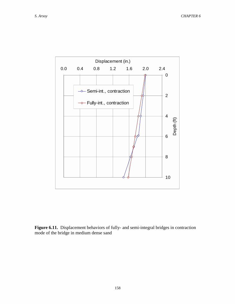
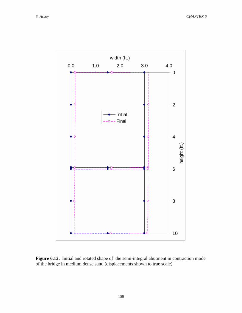
The behavior of the semi-integral abutments was also explored in the contraction
mode of the bridge by applying a lateral load through the bridge beams to pull the
abutments away from the approach fill. A semi-integral and a fully integral abutment
were pulled such that the tops of the abutments displaced 2 inches towards the bridge
centerline. Figure 6.11 shows the displaced position of both abutments in medium dense
sand. It can be seen that the bottom of the semi-integral abutment rotates more than the
top, and that the displacement at the top of the piles is less than for the fully integral
abutment, as was the case in the expansion mode. The initial and the displaced geometry
of the semi-integral abutment are shown in Figure 6.12. The computed pile stresses were
40% smaller for the semi-integral abutment than for the integral abutment.
S. Arsoy CHAPTER 6
143143
In conclusion, it appears that semi-integral abutments offer advantages over the fully
integral abutments as far as the pile stresses are concerned. The advantages are much
more significant in the contraction mode of the bridge.
6.9. Proposed Method to Account for Soil Structure Interaction Effects in Design ofPiles Supporting Integral Abutment Bridges
Finite element analyses indicate that movements of the approach fill cause the
foundation soil to behave as if it were softer. This is somewhat analogous to soil-pile-soil
interaction in pile groups. As a result of this interaction, piles in a group carry smaller
shear loads and are less severely stressed than are single piles subjected to the same
displacement at the pile head. A conventional way of considering the pile group effects
is to reduce the soil resistance using p-multipliers. A similar procedure can be used in the
case of piles supporting integral bridges, as a means of accounting for approach
fill/foundation soil interaction.
The following procedure was used to determine appropriate values of p-multiplier to
account for the approach fill effect:
Step 1: A finite element analysis was performed to evaluate the shear, the
displacement, and the slope at the pile head, with the approach fill in place.
Step 2: Using LPILE, the shear and the slope from step 1 were imposed at the head
of a single pile.
Step 3: The value of the p-multiplier in LPILE was varied until the calculated
displacement in this step becomes equal to the displacement in step 1 for the same
pile head shear and slope.
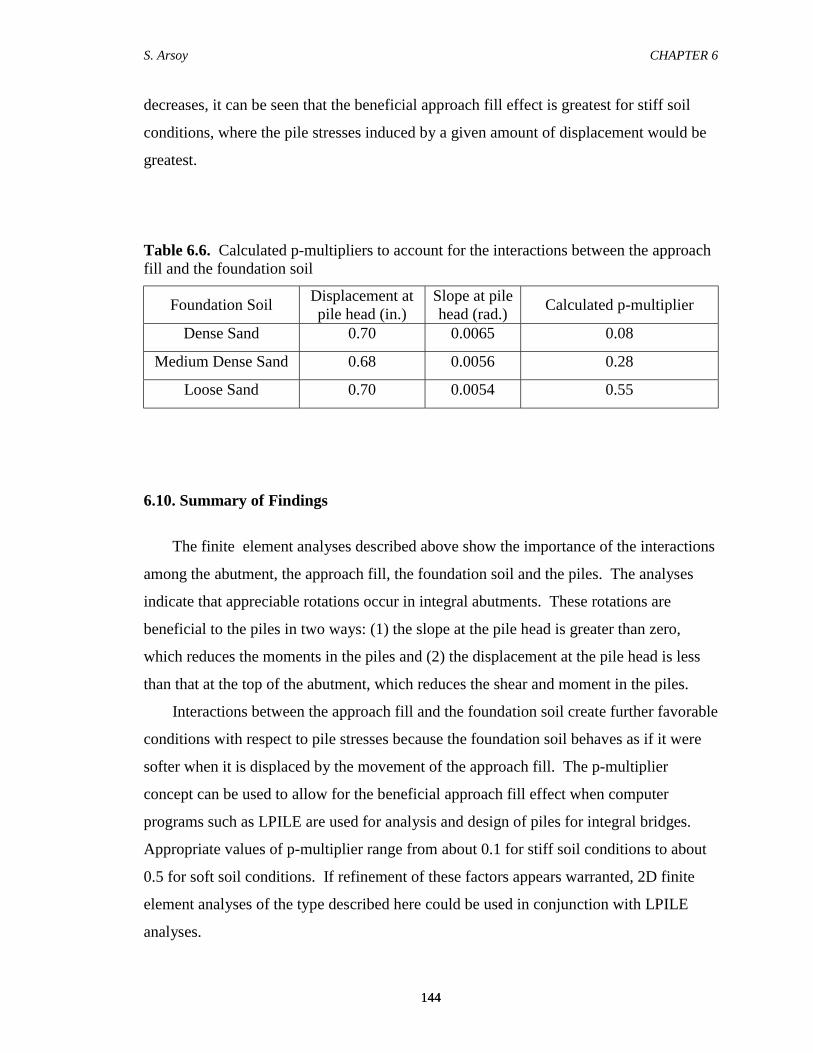
Similar analyses were conducted for loose and dense sand. The values of the p-
multiplier found in these analyses are shown in Table 6.6. As can be seen in this table,
the reduction in stiffness varies from 0.08 for dense sand to 0.55 for loose sand. Because
pile stresses increase with sand density, and decrease as the value of the p-multiplier
S. Arsoy CHAPTER 6
144144
decreases, it can be seen that the beneficial approach fill effect is greatest for stiff soil
conditions, where the pile stresses induced by a given amount of displacement would be
greatest.
Table 6.6. Calculated p-multipliers to account for the interactions between the approachfill and the foundation soil
Foundation Soil Displacement atpile head (in.)
Slope at pilehead (rad.) Calculated p-multiplier
Dense Sand 0.70 0.0065 0.08
Medium Dense Sand 0.68 0.0056 0.28
Loose Sand 0.70 0.0054 0.55
6.10. Summary of Findings
The finite element analyses described above show the importance of the interactions
among the abutment, the approach fill, the foundation soil and the piles. The analyses
indicate that appreciable rotations occur in integral abutments. These rotations are
beneficial to the piles in two ways: (1) the slope at the pile head is greater than zero,
which reduces the moments in the piles and (2) the displacement at the pile head is less
than that at the top of the abutment, which reduces the shear and moment in the piles.
Interactions between the approach fill and the foundation soil create further favorable
conditions with respect to pile stresses because the foundation soil behaves as if it were
softer when it is displaced by the movement of the approach fill. The p-multiplier
concept can be used to allow for the beneficial approach fill effect when computer
programs such as LPILE are used for analysis and design of piles for integral bridges.
Appropriate values of p-multiplier range from about 0.1 for stiff soil conditions to about
0.5 for soft soil conditions. If refinement of these factors appears warranted, 2D finite
element analyses of the type described here could be used in conjunction with LPILE
analyses.
S. Arsoy CHAPTER 6
145145
The finite element analyses indicate that semi-integral abutments such as the one
shown in Figure 6.2 offer benefits over fully integral abutments. The benefits of using
semi-integral abutments in reducing the pile stresses are more pronounced in the
contraction mode of the bridges than the expansion mode.
6.11. Recommendations for Future Work
It would be desirable to instrument abutments of integral bridges and piles
supporting integral bridges to investigate the rotation behavior of semi-integral
abutments, and to investigate pile stresses. Data from such tests would be very useful in
validating the findings of this study.
S. Arsoy CHAPTER 6
146
Figure 6.1. Geometry of bridge considered in finite element analyses
GirderW44x2858' spacing
Abutment10' heigh3' wide
PileHP10x426' apart
150'
ApproachFill
100' 50'
CL
Firm Soil
FoundationSoil
S. Arsoy CHAPTER 6
147
Figure 6.2. Enlarged views of fully-integral and semi-integral abutment details
Girder
Abutment
Pile
FULLY INTEGRAL
Girder
Abutment
Pile
Pile Cap
Dowel
SEMI-INTEGRAL
S. Arsoy CHAPTER 6
148
Figu
re 6
.3.
Fini
te e
lem
ent m
esh
used
for t
he b
ridge
ana
lyze
d
12.2 m (40 ft)24
.4 m
(80
ft)
Slop
e1V
:2V
5.2
m (
17 ft
)
30.5
m (1
00 ft
)15
.3 m
(50
ft)
70.1
m (2
30 ft
)
S. Arsoy CHAPTER 6
149
Figure 6.4. Finite element mesh of the area of the fully-integral abutment
Zero thickness interface elements
Bridge Superstructure
Pile
S. Arsoy CHAPTER 6
150
Figure 6.5. Finite element mesh of the area of the semi-integral abutment
Zero thicknessinterface elements
Pile
Joint filler
7/8" dowel
Bridge Superstructure
S. Arsoy CHAPTER 6
151
Figure 6.6. Comparison of results for SAGE and LPILE for a fully fixed head pile
0
4
8
12
16
20
-25 -20 -15 -10 -5 0 5
Shear (kip)
Dep
th (f
t)
SAGE - fixed head
LPILE - fixed head
0
4
8
12
16
20
-0.5 -0.4 -0.3 -0.2 -0.1 0.0 0.1
Displacement (in.)
Dep
th (f
t)
SAGE - fixed head
LPILE - fixed head
S. Arsoy CHAPTER 6
152
Figure 6.6 (Continued). Comparison of results for SAGE and LPILE for a fully fixedhead pile
0
4
8
12
16
20
-300 0 300 600 900
Bending Moment (in-kip)
Dep
th (f
t)
SAGE - fixed head
LPILE - fixed head
S. Arsoy CHAPTER 6
153
Figure 6.7. Comparison of results for SAGE and LPILE for a partially fixed head pile
0
4
8
12
16
20
-0.6 -0.4 -0.2 0.0
Displacement (in.)
Dep
th (f
t)
SAGE - slope: 0.005
LPILE - slope: 0.005
0
4
8
12
16
20
-20 -15 -10 -5 0 5 10
Shear (kip)
Dep
th (f
t)
SAGE - slope: 0.005
LPILE - slope: 0.005
S. Arsoy CHAPTER 6
154
Figure 6.7 (Continued). Comparison of results for SAGE and LPILE for a partiallyfixed head pile
0
4
8
12
16
20
-300 -100 100 300 500
Bending Moment (in-kip)
Dep
th (f
t)
SAGE - slope: 0.005
LPILE - slope: 0.005
S. Arsoy CHAPTER 6
155
Figure 6.8. Sketches of the geometry of the bridge analyzed w/ and w/o the approach fill
Bridge w/o approach fill
Bridge w/ approach fill
S. Arsoy CHAPTER 6
156
Figure 6.9. Displacement behaviors of fully- and semi-integral bridges in expansionmode of the bridge in medium dense sand
0
2
4
6
8
10
-2.4 -2.0 -1.6 -1.2 -0.8 -0.4 0.0Displacement (in.)
Dep
th (f
t)
Semi-int., Expansion
Fully-int., Expansion
S. Arsoy CHAPTER 6
157
Figure 6.10. Initial and rotated shape of the semi-integral abutment in expansion modeof the bridge in medium dense sand (displacements shown to true scale)
0
2
4
6
8
10
-1.0 0.0 1.0 2.0 3.0width (ft.)
heig
ht (f
t.)
InitialFinal
S. Arsoy CHAPTER 6
158
Figure 6.11. Displacement behaviors of fully- and semi-integral bridges in contractionmode of the bridge in medium dense sand
0
2
4
6
8
10
0.0 0.4 0.8 1.2 1.6 2.0 2.4Displacement (in.)
Dep
th (f
t)
Semi-int., contraction
Fully-int., contraction
S. Arsoy CHAPTER 6
159
Figure 6.12. Initial and rotated shape of the semi-integral abutment in contraction modeof the bridge in medium dense sand (displacements shown to true scale)
0
2
4
6
8
10
0.0 1.0 2.0 3.0 4.0width (ft.)
heig
ht (f
t.)
InitialFinal