Embed Size (px)
Citation preview
CHAPTER 6:
IMPACTS ON WASTE PLANNING AND
MANAGEMENT
Second Order Draft for Stakeholder Comment
Integrating Author: Suzan Oelofse
Contributing Authors: Johan Schoonraad
Corresponding Authors: Dave Baldwin
Peer Reviewers: Carin Bosman, Ray Gosine, Eddie Hannekom, Dave Yoxtheimer
Page 6-1
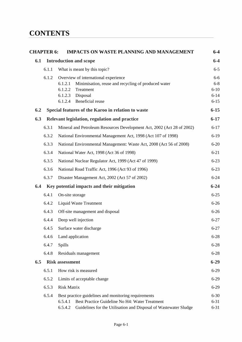
CONTENTS
CHAPTER 6: IMPACTS ON WASTE PLANNING AND MANAGEMENT 6-4
6.1 Introduction and scope 6-4
6.1.1 What is meant by this topic? 6-5
6.1.2 Overview of international experience 6-6
6.1.2.1 Minimisation, reuse and recycling of produced water 6-8
6.1.2.2 Treatment 6-10
6.1.2.3 Disposal 6-14
6.1.2.4 Beneficial reuse 6-15
6.2 Special features of the Karoo in relation to waste 6-15
6.3 Relevant legislation, regulation and practice 6-17
6.3.1 Mineral and Petroleum Resources Development Act, 2002 (Act 28 of 2002) 6-17
6.3.2 National Environmental Management Act, 1998 (Act 107 of 1998) 6-19
6.3.3 National Environmental Management: Waste Act, 2008 (Act 56 of 2008) 6-20
6.3.4 National Water Act, 1998 (Act 36 of 1998) 6-21
6.3.5 National Nuclear Regulator Act, 1999 (Act 47 of 1999) 6-23
6.3.6 National Road Traffic Act, 1996 (Act 93 of 1996) 6-23
6.3.7 Disaster Management Act, 2002 (Act 57 of 2002) 6-24
6.4 Key potential impacts and their mitigation 6-24
6.4.1 On-site storage 6-25
6.4.2 Liquid Waste Treatment 6-26
6.4.3 Off-site management and disposal 6-26
6.4.4 Deep well injection 6-27
6.4.5 Surface water discharge 6-27
6.4.6 Land application 6-28
6.4.7 Spills 6-28
6.4.8 Residuals management 6-28
6.5 Risk assessment 6-29
6.5.1 How risk is measured 6-29
6.5.2 Limits of acceptable change 6-29
6.5.3 Risk Matrix 6-29
6.5.4 Best practice guidelines and monitoring requirements 6-30
6.5.4.1 Best Practice Guideline No H4: Water Treatment 6-31
6.5.4.2 Guidelines for the Utilisation and Disposal of Wastewater Sludge 6-31
Page 6-2
6.5.4.3 National Norms and Standards for Assessment of Waste for Landfill
Disposal 6-31
6.5.4.4 Norms and Standards for Disposal of Waste to Landfill 6-32
6.5.4.5 National Norms and Standards for Storage of Waste 6-32
6.5.4.6 Minimum Requirements for Monitoring of Water Quality at Waste
Management Facilities 6-32
6.6 Topics on which information is inadequate for decision-making 6-37
6.7 References 6-37
6.8 Addendum A6: Tabulated detailed information 6-41
Tables
Table 6.1: Produced water minimization technologies (Veil, 2015). 6-8
Table 6.2: Examples of water reuse and recycle management options and some of the specific uses
(Veil, 2015). 6-9
Table 6.3: Treatment technologies designed to remove salts and other inorganic compounds from
produced water (Veil, 2015). 6-11
Table 6.4: Treatment technologies designed to remove oil and grease and other organics from produced
water water (Veil, 2015). 6-12
Table 6.5: Water disposal methods (Veil, 2015). 6-15
Table 6.6: Risk Matrix. 6-29
Table 6.7: Monitoring requirements for general and hazardous waste disposal facilities and sewage
sludge 6-35
Figures
Figure 6.1: Map of the study area showing waste facilities for general landfills and Waste Water
Treatment Works 6-16
Figure 6.2: Water use categories as defined by the Pricing Strategy (RSA, 2015). 6-23
Figure 6.3: A schematic presentation of these monitoring systems (DWAF, 1998b). 6-33
Figure 6.4: Minimum Requirements (DWAF, 1998b) also provide guidance on borehole design 6-36

Page 6-3
Executive Summary 1
This chapter focus on the management aspects of solid and liquid waste generated during 2
shale gas development (SGD) by identifying the 3
potential impacts and mitigation measures required 4
to reduce the risks posed by waste to the 5
environment and communities. 6
Waste must be managed in an integrated way in-line 7
with the waste management hierarchy and the 8
principles for integrated waste management in 9
South Africa. The emphasis here is to minimise 10
waste arisings, promote the use of non-hazardous 11
chemicals, reuse and recycling and minimise the 12
impact of waste on water, the environment and 13
communities. 14
Schedule 3 of the Waste Amendment Act, 2014 15
classifies waste from gas exploration and development as hazardous waste. It is likely that 16
most of the waste generated will be classified as Type 1 hazardous waste requiring disposal at 17
a Class A or H:H landfill. Municipal landfill sites in the study area do not meet the design 18
requirements to accept Type 1 hazardous waste. The closest commercial facilities to the 19
study area that are duly authorised to accept Type 1 hazardous waste is Aloes in Port 20
Elizabeth and Vissershok in Cape Town. 21
Limited capacity and skills of municipalities in the study area is a serious issue for municipal 22
waste management and requires intervention to deal with any additional loads of domestic or 23
other general waste streams. 24
Available waste water infrastructure in the study area is under pressure and requires urgent 25
intervention. The technologies and capacity at these already stressed facilities are not 26
sufficient or appropriate to treat wastewater from SGD. 27
The current, constantly changing, waste management legislation will not be able to deal with 28
waste from shale gas exploration and production operations effectively despite the 29
promulgation of the Regulations for Petroleum Exploration and Production, 2015 which 30
amongst other, prescribe: an impermeable site underlay to prevent environmental 31
contamination; disclosure of the content of drilling fluids through material safety data sheets 32
and disclosure of the chemical composition of the fracking fluids; above-ground storage tanks 33
for fracturing fluids, flowback and produced water; and prohibition of underground disposal, 34
including the use of re-injection disposal wells for waste water and drilling muds and the 35
prohibition of certain listed substances from being used in the fracking process.36
Page 6-4
CHAPTER 6: IMPACTS ON WASTE PLANNING AND 1
MANAGEMENT 2
6.1 Introduction and scope 3
The management of waste is an integral 4
part of responsible oil and gas 5
exploration and production activities but 6
can be especially challenging in areas 7
where supporting infrastructure or 8
regulatory frameworks are not well 9
developed (OGP, 2009). 10
11
Waste is defined in South African law in 12
both the National Water Act, 1998 and in 13
the National Environmental 14
Management: Waste Act, 2008. The two 15
definitions differ in that the Water Act 16
defines waste based on its potential to pollute the water resource (RSA, 1998) while the Waste Act 17
defines waste as any substance, material or object that is unwanted, rejected, abandoned, discarded or 18
disposed of, or that is intended or required to be disposed of, irrespective of whether or not such 19
substance material or object can be reused, recycled or recovered (RSA, 2008 as amended). When 20
considering waste in the context of this study, both definitions will apply. 21
22
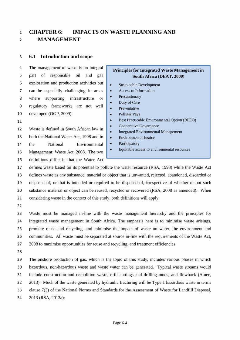
Waste must be managed in-line with the waste management hierarchy and the principles for 23
integrated waste management in South Africa. The emphasis here is to minimise waste arisings, 24
promote reuse and recycling, and minimise the impact of waste on water, the environment and 25
communities. All waste must be separated at source in-line with the requirements of the Waste Act, 26
2008 to maximise opportunities for reuse and recycling, and treatment efficiencies. 27
28
The onshore production of gas, which is the topic of this study, includes various phases in which 29
hazardous, non-hazardous waste and waste water can be generated. Typical waste streams would 30
include construction and demolition waste, drill cuttings and drilling muds, and flowback (Amec, 31
2013). Much of the waste generated by hydraulic fracturing will be Type 1 hazardous waste in terms 32
clause 7(3) of the National Norms and Standards for the Assessment of Waste for Landfill Disposal, 33
2013 (RSA, 2013a): 34
Principles for Integrated Waste Management in
South Africa (DEAT, 2000)
Sustainable Development
Access to Information
Precautionary
Duty of Care
Preventative
Polluter Pays
Best Practicable Environmental Option (BPEO)
Cooperative Governance
Integrated Environmental Management
Environmental Justice
Participatory
Equitable access to environmental resources
Page 6-5
“If a particular chemical substance in a waste is not listed with corresponding 1
LCT and TCT limits in section 6 of these Norms and Standards, and the waste 2
has been classified as hazardous in terms of regulation 4(2) of the Regulations 3
based on the health or environmental hazard characteristics of the particular 4
element or chemical substance, the following applies 5
(a) the waste is considered to be Type 1 Waste;” 6
7
Inappropriate treatment and management of these wastes and spills of fracking fluids has the potential 8
to threaten human health and safety and impact negatively on water resources and the environment 9
(Kiboub, 2011; OGP, 2009). Hydraulic fracturing uses a large number of chemicals, including some 10
known hazardous substances (e.g., the foaming agent 2-butoxyethanol), and brings many potentially 11
dangerous compounds to the surface, such as hydrocarbons, varying amounts of BTEX (benzene, 12
toluene, ethylbenzene, xylenes) compounds, brine, and other naturally occurring geological 13
components (e.g., arsenic, radionuclides) (Council of Canadian Academies, 2014; Zhang et al., 2016). 14
This section of the report will therefore assess all waste and waste water streams generated as a result 15
of shale gas development (SGD), and the potential risks associated with the various waste and waste 16
water management options. It will also propose mitigation measures to protect human health and the 17
environment against the effects caused by spills and the collection, transport, treatment, storage and 18
disposal of waste and waste water. 19
6.1.1 What is meant by this topic? 20
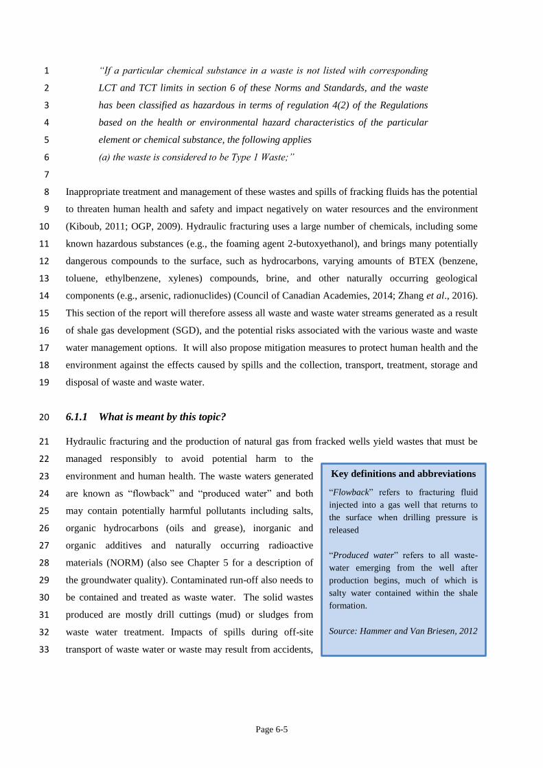
Hydraulic fracturing and the production of natural gas from fracked wells yield wastes that must be 21
managed responsibly to avoid potential harm to the 22
environment and human health. The waste waters generated 23
are known as “flowback” and “produced water” and both 24
may contain potentially harmful pollutants including salts, 25
organic hydrocarbons (oils and grease), inorganic and 26
organic additives and naturally occurring radioactive 27
materials (NORM) (also see Chapter 5 for a description of 28
the groundwater quality). Contaminated run-off also needs to 29
be contained and treated as waste water. The solid wastes 30
produced are mostly drill cuttings (mud) or sludges from 31
waste water treatment. Impacts of spills during off-site 32
transport of waste water or waste may result from accidents, 33
Key definitions and abbreviations
“Flowback” refers to fracturing fluid
injected into a gas well that returns to
the surface when drilling pressure is
released
“Produced water” refers to all waste-
water emerging from the well after
production begins, much of which is
salty water contained within the shale
formation.
Source: Hammer and Van Briesen, 2012
Page 6-6
from inadequate management or training, and from illicit dumping. Domestic solid waste associated 1
with worker deployment to the area and opportunistic migrants looking for employment and other 2
economic opportunities are also considered. 3
4
Issues not covered in this chapter are non-water related impacts of waste water management (with 5
limited exceptions). Such impacts include air emissions from trucks used to haul waste water and 6
waste (refer to chapter 3), noise and traffic impacts from those trucks (refer to chapters 16 and 18), 7
soil contamination and land disturbance impact from the construction of waste water management 8
facilities (refer to chapters 5 and 7). 9
10
Assumptions: Operators/prospectors must fully disclose the composition of the fracturing fluid 11
additives, consistent with the provisions of the Regulations for Petroleum Exploration and Production, 12
2015, as this will determine the treatment options required to ensure correct treatment and proper 13
management of this waste stream. The waste stream has been pre-defined as hazardous waste in 14
Schedule 3 of the Waste Amendment Act, 2014 (RSA, 2014). 15
6.1.2 Overview of international experience 16
Disposal of drilling and fracturing wastes, as well as spills of fracturing fluids and waste, poses a 17
number of potential environmental and health risks. Surface spills of fracturing fluid may pose a 18
greater contamination risk than hydraulic fracturing itself (Grout and Grimshaw, 2012). Released 19
materials include fuels, drilling mud and cuttings, and chemicals (particularly for hydraulic 20
fracturing). Hydraulic fracturing chemicals in concentrated form (before mixing) at the surface 21
present a more significant risk above ground than as a result of injection in the deep subsurface (Grout 22
and Grimshaw, 2012). Leaks and spills associated with SGD may occur at the drill pad or during 23
transport of chemicals and waste materials. Sources at the wellsite include the drill rig and other 24
operating equipment, storage tanks, impoundments or pits, and leaks or blowouts at the wellhead. The 25
primary risk of uncontrolled releases is generally to surface water and groundwater resources (Grout 26
and Grimshaw, 2012). 27
28
Many of the waste streams generated by hydraulic fracturing are the same as or similar to those of 29
conventional oil and gas production (Grout and Grimshaw, 2012). The flowback and produced water 30
generated by hydraulic fracturing may pose a serious risk to the surrounding environment and public 31
health because this wastewater usually contains many toxic chemicals and high levels of total 32
dissolved solids (TDS) (Zhang et al., 2016). The composition of waste waters changes over the 33
lifetime of the well with produced water increasing in salinity in the latter stages of shale gas 34
extraction (Koppelman et al., 2012). The management of these wastes may be the greatest challenge 35
Page 6-7
of shale gas regulation by the responsible authorities (Grout and Grimshaw, 2012). The US 1
Environmental Protection Agency reported groundwater contamination in Pavillion, Wyoming as a 2
direct result of improper operational practices associated with hydraulic fracturing waste management 3
(DiGiulio et al., 2011). “Detection of high concentrations of benzene, xylenes, gasoline range 4
organics, diesel range organics, and total purgeable hydrocarbons in ground water samples from 5
shallow monitoring wells near pits indicates that pits are a source of shallow ground water 6
contamination in the area of investigation. Pits were used for disposal of drilling cuttings, flowback, 7
and produced water” (DiGiulio et al., 2011:33). 8
9
According to Grout and Grimshaw (2012) regulations for waste storage primarily address temporary 10
pits and tanks for drilling fluid and cuttings and flowback and produced water. These regulations 11
typically include requirements for pit liners, freeboard (excess volumetric capacity), and closure, all 12
of which have the objective of preventing soil and water contamination. Some states in the US are 13
adopting provisions which require that drilling and fracturing waste must be stored in tanks rather 14
than pits to reduce the potential impacts on the environment (Grout and Grimshaw, 2012). Open 15
storage ponds are not allowed in the UK (Koppelman et al., 2012) or in South Africa (RSA, 2015a). 16
17
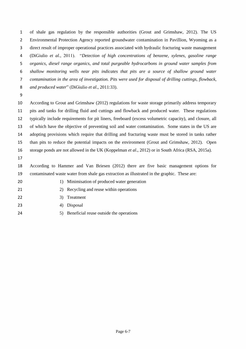
According to Hammer and Van Briesen (2012) there are five basic management options for 18
contaminated waste water from shale gas extraction as illustrated in the graphic. These are: 19
1) Minimisation of produced water generation 20
2) Recycling and reuse within operations 21
3) Treatment 22
4) Disposal 23
5) Beneficial reuse outside the operations 24
Page 6-8
1
6.1.2.1 Minimisation, reuse and recycling of produced water 2
Water use and waste water minimisation technologies are still being developed and the effect they 3
will have on long-term produced water quantities is uncertain (Hammer and Van Briesen, 2012). 4
Challenges to reuse may include removing constituents that could affect well performance (salts, 5
suspended solids, microorganisms and scale forming chemicals) and adjusting the stimulation 6
chemistry with chemical additives that work in saltier waters (Hammer and Van Briesen, 2012). 7
8
Minimising the volume of produced water that is generated to the surface is a way to simplify water 9
management options and costs. To achieve produced water minimization, processes are modified, 10
technologies adapted or products are substituted so that less water is generated (Veil, 2015). 11
12
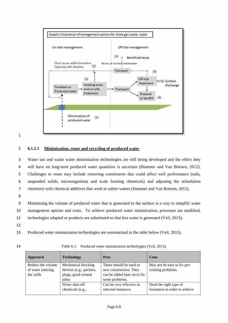
Produced water minimization technologies are summarized in the table below (Veil, 2015). 13
Table 6.1: Produced water minimization technologies (Veil, 2015). 14
Approach Technology Pros Cons
Reduce the volume
of water entering
the wells
Mechanical blocking
devices (e.g., packers,
plugs, good cement
jobs)
These should be used in
new construction. They
can be added later on to fix
some problems.
May not be easy to fix pre-
existing problems.
Water shut-off
chemicals (e.g.,
Can be very effective in
selected instances,
Need the right type of
formation in order to achieve
Page 6-9
Approach Technology Pros Cons
polymer gels) primarily in sandstone and
limestone formations.
cost-effective results.
Reduce the volume
of water managed
at the surface by
remote separation
Dual completion wells
(downhole water sink)
Can be very effective in
selected instances.
Limited prior use. Makes wells
more complex.
Downhole oil/water
separation
May be a good future
technology.
Earlier trials were inconsistent
and the technology went out of
favour. New designs and good
candidate wells are needed to
bring back this technology.
1
The opportunity for reuse and recycling is greater during the flowback period than during the 2
production phase. Produced water generated during the lifetime of the well can be collected and 3
repurposed for operations at other wells, but this requires transport to new well pads which may be 4
more costly than transport to disposal or treatment locations. Logistics and economics therefore 5
control the reuse opportunity (Hammer and Van Briesen, 2012). Reinjection for enhanced recovery is 6
a fairly common practice in the USA and elsewhere (Veil, 2015). In general, increased emphasis is 7
being placed on requirements for waste water reduction through reuse and recycling of hydraulic 8
fracturing fluids (Grout and Grimshaw, 2012). Desalination technologies are being developed to 9
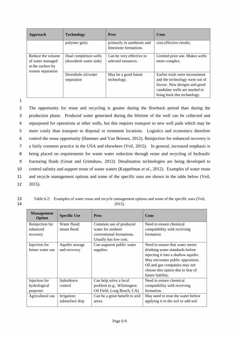
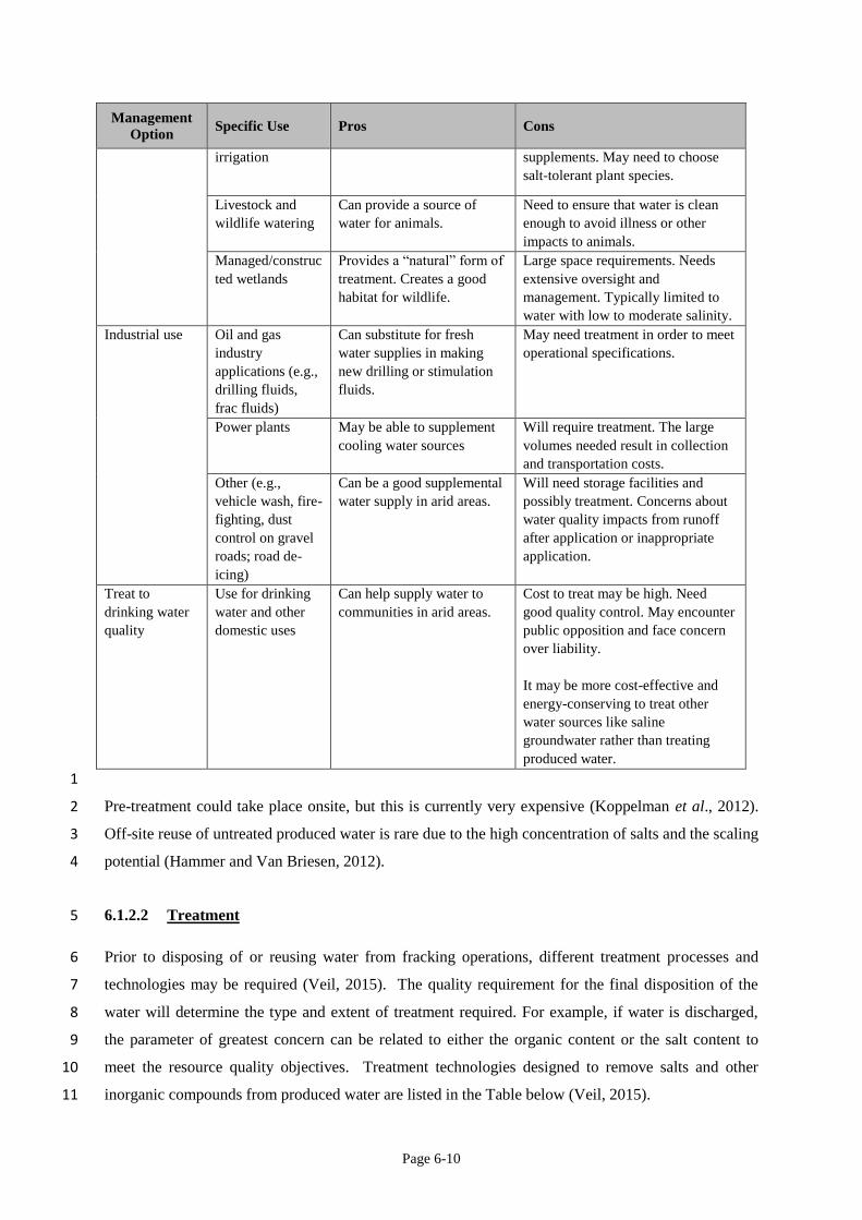
control salinity and support reuse of waste waters (Koppelman et al., 2012). Examples of water reuse 10
and recycle management options and some of the specific uses are shown in the table below (Veil, 11
2015). 12
Table 6.2: Examples of water reuse and recycle management options and some of the specific uses (Veil, 13 2015). 14
Management
Option Specific Use Pros Cons
Reinjection for
enhanced
recovery
Water flood;
steam flood
Common use of produced
water for onshore
conventional formations.
Usually has low cost.
Need to ensure chemical
compatibility with receiving
formation
Injection for
future water use
Aquifer storage
and recovery
Can augment public water
supplies.
Need to ensure that water meets
drinking water standards before
injecting it into a shallow aquifer.
May encounter public opposition.
Oil and gas companies may not
choose this option due to fear of
future liability.
Injection for
hydrological
purposes
Subsidence
control
Can help solve a local
problem (e.g., Wilmington
Oil Field, Long Beach, CA).
Need to ensure chemical
compatibility with receiving
formation.
Agricultural use Irrigation;
subsurface drip
Can be a great benefit to arid
areas.
May need to treat the water before
applying it to the soil or add soil
Page 6-10
Management
Option Specific Use Pros Cons
irrigation supplements. May need to choose
salt-tolerant plant species.
Livestock and
wildlife watering
Can provide a source of
water for animals.
Need to ensure that water is clean
enough to avoid illness or other
impacts to animals.
Managed/construc
ted wetlands
Provides a “natural” form of
treatment. Creates a good
habitat for wildlife.
Large space requirements. Needs
extensive oversight and
management. Typically limited to
water with low to moderate salinity.
Industrial use Oil and gas
industry
applications (e.g.,
drilling fluids,
frac fluids)
Can substitute for fresh
water supplies in making
new drilling or stimulation
fluids.
May need treatment in order to meet
operational specifications.
Power plants May be able to supplement
cooling water sources
Will require treatment. The large
volumes needed result in collection
and transportation costs.
Other (e.g.,
vehicle wash, fire-
fighting, dust
control on gravel
roads; road de-
icing)
Can be a good supplemental
water supply in arid areas.
Will need storage facilities and
possibly treatment. Concerns about
water quality impacts from runoff
after application or inappropriate
application.
Treat to
drinking water
quality
Use for drinking
water and other
domestic uses
Can help supply water to
communities in arid areas.
Cost to treat may be high. Need
good quality control. May encounter
public opposition and face concern
over liability.
It may be more cost-effective and
energy-conserving to treat other
water sources like saline
groundwater rather than treating
produced water.
1
Pre-treatment could take place onsite, but this is currently very expensive (Koppelman et al., 2012). 2
Off-site reuse of untreated produced water is rare due to the high concentration of salts and the scaling 3
potential (Hammer and Van Briesen, 2012). 4
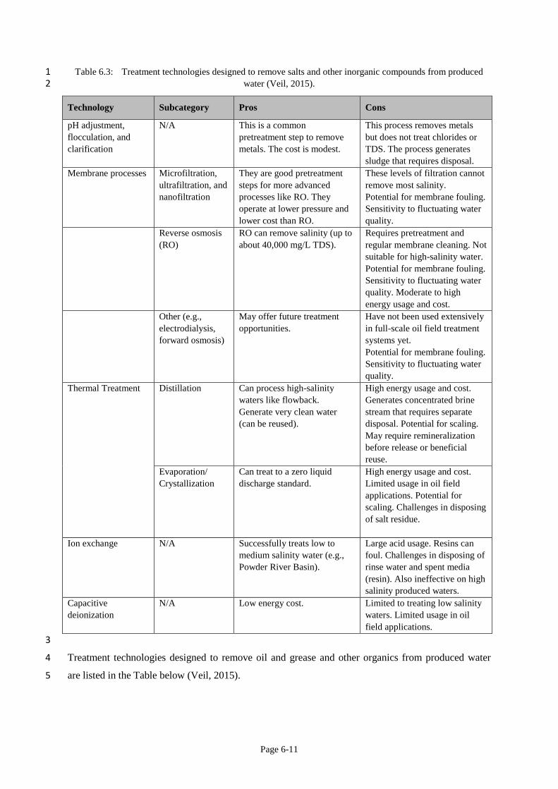
6.1.2.2 Treatment 5
Prior to disposing of or reusing water from fracking operations, different treatment processes and 6
technologies may be required (Veil, 2015). The quality requirement for the final disposition of the 7
water will determine the type and extent of treatment required. For example, if water is discharged, 8
the parameter of greatest concern can be related to either the organic content or the salt content to 9
meet the resource quality objectives. Treatment technologies designed to remove salts and other 10
inorganic compounds from produced water are listed in the Table below (Veil, 2015). 11
Page 6-11
Table 6.3: Treatment technologies designed to remove salts and other inorganic compounds from produced 1 water (Veil, 2015). 2
Technology Subcategory Pros Cons
pH adjustment,
flocculation, and
clarification
N/A This is a common
pretreatment step to remove
metals. The cost is modest.
This process removes metals
but does not treat chlorides or
TDS. The process generates
sludge that requires disposal.
Membrane processes Microfiltration,
ultrafiltration, and
nanofiltration
They are good pretreatment
steps for more advanced
processes like RO. They
operate at lower pressure and
lower cost than RO.
These levels of filtration cannot
remove most salinity.
Potential for membrane fouling.
Sensitivity to fluctuating water
quality.
Reverse osmosis
(RO)
RO can remove salinity (up to
about 40,000 mg/L TDS).
Requires pretreatment and
regular membrane cleaning. Not
suitable for high-salinity water.
Potential for membrane fouling.
Sensitivity to fluctuating water
quality. Moderate to high
energy usage and cost.
Other (e.g.,
electrodialysis,
forward osmosis)
May offer future treatment
opportunities.
Have not been used extensively
in full-scale oil field treatment
systems yet.
Potential for membrane fouling.
Sensitivity to fluctuating water
quality.
Thermal Treatment Distillation Can process high-salinity
waters like flowback.
Generate very clean water
(can be reused).
High energy usage and cost.
Generates concentrated brine
stream that requires separate
disposal. Potential for scaling.
May require remineralization
before release or beneficial
reuse.
Evaporation/
Crystallization
Can treat to a zero liquid
discharge standard.
High energy usage and cost.
Limited usage in oil field
applications. Potential for
scaling. Challenges in disposing
of salt residue.
Ion exchange N/A Successfully treats low to
medium salinity water (e.g.,
Powder River Basin).
Large acid usage. Resins can
foul. Challenges in disposing of
rinse water and spent media
(resin). Also ineffective on high
salinity produced waters.
Capacitive
deionization
N/A Low energy cost. Limited to treating low salinity
waters. Limited usage in oil
field applications.
3
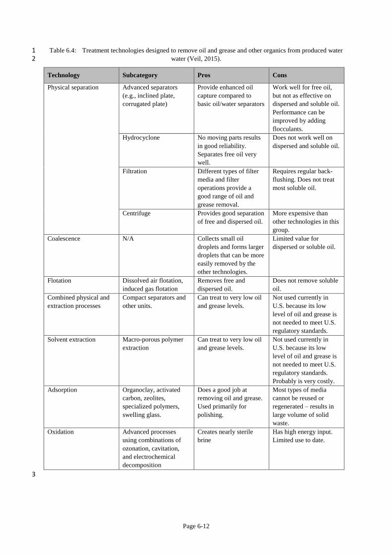
Treatment technologies designed to remove oil and grease and other organics from produced water 4
are listed in the Table below (Veil, 2015). 5
Page 6-12
Table 6.4: Treatment technologies designed to remove oil and grease and other organics from produced water 1 water (Veil, 2015). 2
Technology Subcategory Pros Cons
Physical separation Advanced separators
(e.g., inclined plate,
corrugated plate)
Provide enhanced oil
capture compared to
basic oil/water separators
Work well for free oil,
but not as effective on
dispersed and soluble oil.
Performance can be
improved by adding
flocculants.
Hydrocyclone No moving parts results
in good reliability.
Separates free oil very
well.
Does not work well on
dispersed and soluble oil.
Filtration Different types of filter
media and filter
operations provide a
good range of oil and
grease removal.
Requires regular back-
flushing. Does not treat
most soluble oil.
Centrifuge Provides good separation
of free and dispersed oil.
More expensive than
other technologies in this
group.
Coalescence N/A Collects small oil
droplets and forms larger
droplets that can be more
easily removed by the
other technologies.
Limited value for
dispersed or soluble oil.
Flotation Dissolved air flotation,
induced gas flotation
Removes free and
dispersed oil.
Does not remove soluble
oil.
Combined physical and
extraction processes
Compact separators and
other units.
Can treat to very low oil
and grease levels.
Not used currently in
U.S. because its low
level of oil and grease is
not needed to meet U.S.
regulatory standards.
Solvent extraction Macro-porous polymer
extraction
Can treat to very low oil
and grease levels.
Not used currently in
U.S. because its low
level of oil and grease is
not needed to meet U.S.
regulatory standards.
Probably is very costly.
Adsorption Organoclay, activated
carbon, zeolites,
specialized polymers,
swelling glass.
Does a good job at
removing oil and grease.
Used primarily for
polishing.
Most types of media
cannot be reused or
regenerated – results in
large volume of solid
waste.
Oxidation Advanced processes
using combinations of
ozonation, cavitation,
and electrochemical
decomposition
Creates nearly sterile
brine
Has high energy input.
Limited use to date.
3
Page 6-13
Veil (2015) reports that new produced water technologies and products are being introduced to the 1
marketplace each month; the technologies listed in the Tables are major technology categories that 2
were in use in 2014. 3
4
Treatment is the most complex management option and can be done on- or off-site and in conjunction 5
with recycling, reuse, discharge and disposal. On-site treatment is designed for reuse only and will 6
incorporate the minimum treatment technology required for reuse without compromising the 7
chemistry of the hydraulic fracturing makeup water (Hammer and Van Briesen, 2012). 8
9
Desalination is possible, but is rarely necessary to produce water suitable for reuse in fracking 10
operations (Hammer and Van Briesen, 2012). Biofouling of membranes by organic material has 11
historically been responsible for the largest number of failures in reverse osmosis desalination 12
processes. Thus, effective pretreatment of oilfield-produced brines is necessary to prevent biofouling 13
and scaling of reverse osmosis membranes (Lee et al., 2002). 14
15
Treatment is predominantly done off-site and therefore requires transport of the waste water (Hammer 16
and Van Briesen, 2012). Off-site options and decisions are more complex and will require initial 17
analysis of the water to determine its fate. Regardless of its ultimate fate, preliminary treatment is 18
likely to be required (Hammer and Van Briesen, 2012). 19
20
The main contaminants to be removed during treatment are: 1) salts, including metals, 2) organic 21
hydrocarbons (sometimes referred to as oil and grease), 3) inorganic and organic additives, and 4) 22
naturally occurring radio-active materials (NORM). The treatment technology to employ can only be 23
determined through complete chemical analysis of the water. Significant concern has been raised 24
regarding the nature of the additives, with 29 identified as of particular concern for human health and 25
13 identified as probable or known human carcinogens (Hammer and Van Briesen, 2012). Among the 26
most notable are 2-butoxyethanol (2BE), naphthalene, benzene and polyacrylamide. A list of the 27
chemicals of concern present in fracking fluids is provided in Table 1 in the Addendum. 28
29
In the US, there are calls for operators to disclose fully the composition of the fracturing fluid 30
additives and it is already a requirement in the UK (DiGiulio et al, 2011; Koppelman et al., 2012) and 31
included in South African regulations (RSA, 2015a). 32
33
Shale gas operators in the US are known to have sent waste water to publicly owned treatment works 34
for treatment (Hammer and Van Briesen, 2012), but this practice has become controversial and has 35
been banned in some states, while other states require pre-treatment before discharge into publicly 36
owned treatment works (Grout and Grimshaw, 2012). In July 2011, 15 treatment facilities were 37
Page 6-14
exempted from compliance with the regulations, meaning that they were allowed to discharge treated 1
waste water with concentrations exceeding the TDS and chlorides limits. Nine of these facilities were 2
publicly owned waste water treatment plants. An alternative is treatment of produced water at 3
dedicated brine or industrial waste water facilities (Hammer and Van Briesen, 2012). The USEPA 4
has indicated that waste water treatment standards will be developed for shale gas waste water (Grout 5
and Grimshaw, 2012). 6
7
Treated water may be discharged, shipped back to the well site for reuse or diverted for beneficial 8
reuse or resource extraction, depending on the final quality (Hammer and Van Briesen, 2012). 9
6.1.2.3 Disposal 10
Direct disposal above ground or to soils in the near surface environment, on- or off-site was routine in 11
the early part of the 20th century, and the use of on-site unlined ponds and nearby off-site land 12
applications were common disposal practices (Hammer and van Briesel, 2012). These practices are 13
no longer used due to salt contamination in soils and aquifers. Produced water in the USA is often 14
disposed via underground injection into disposal wells (Hammer and Van Briesen, 2012; Shaffer et 15
al., 2013). A small fraction of produced waste is reportedly discharged to surface water, managed by 16
evaporation ponds, or beneficially reused outside the industry (Shaffer et al, 2013). Some states are 17
re-evaluating the practice of on-site land disposal of waste (Grout and Grimshaw, 2012). Field 18
evaluations on a subset of impoundments and pits used for waste and wastewater storage in the 19
Marcellus Shale development, found several construction and maintenance deficiencies related to the 20
containment systems and transport pipelines (Ziemkiewicz et al., 2014). 21
22
In some shale gas areas, operators manage waste at a centralised waste disposal facility that accepts 23
waste from multiple well sites (Koppelman et al., 2012; Grout and Grimshaw, 2012). These facilities 24
may be subject to general state requirements such as best management practices to protect human 25
health and the environment or to specific requirements such as an operating plan, water well 26
monitoring and storm water diversion (Grout and Grimshaw, 2012). Water disposal methods (Veil, 27
2015) are listed in the Table below. 28
29
Page 6-15
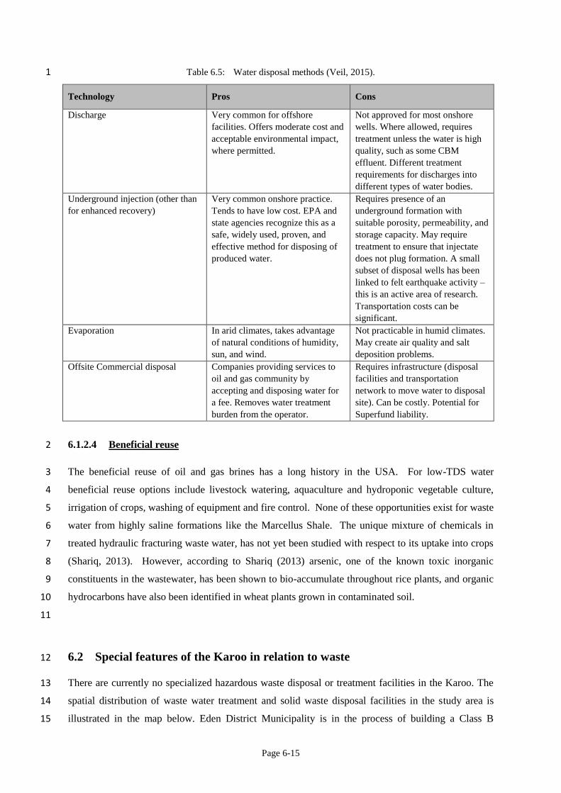
Table 6.5: Water disposal methods (Veil, 2015). 1
Technology Pros Cons
Discharge Very common for offshore
facilities. Offers moderate cost and
acceptable environmental impact,
where permitted.
Not approved for most onshore
wells. Where allowed, requires
treatment unless the water is high
quality, such as some CBM
effluent. Different treatment
requirements for discharges into
different types of water bodies.
Underground injection (other than
for enhanced recovery)
Very common onshore practice.
Tends to have low cost. EPA and
state agencies recognize this as a
safe, widely used, proven, and
effective method for disposing of
produced water.
Requires presence of an
underground formation with
suitable porosity, permeability, and
storage capacity. May require
treatment to ensure that injectate
does not plug formation. A small
subset of disposal wells has been
linked to felt earthquake activity –
this is an active area of research.
Transportation costs can be
significant.
Evaporation In arid climates, takes advantage
of natural conditions of humidity,
sun, and wind.
Not practicable in humid climates.
May create air quality and salt
deposition problems.
Offsite Commercial disposal Companies providing services to
oil and gas community by
accepting and disposing water for
a fee. Removes water treatment
burden from the operator.
Requires infrastructure (disposal
facilities and transportation
network to move water to disposal
site). Can be costly. Potential for
Superfund liability.
6.1.2.4 Beneficial reuse 2
The beneficial reuse of oil and gas brines has a long history in the USA. For low-TDS water 3
beneficial reuse options include livestock watering, aquaculture and hydroponic vegetable culture, 4
irrigation of crops, washing of equipment and fire control. None of these opportunities exist for waste 5
water from highly saline formations like the Marcellus Shale. The unique mixture of chemicals in 6
treated hydraulic fracturing waste water, has not yet been studied with respect to its uptake into crops 7
(Shariq, 2013). However, according to Shariq (2013) arsenic, one of the known toxic inorganic 8
constituents in the wastewater, has been shown to bio-accumulate throughout rice plants, and organic 9
hydrocarbons have also been identified in wheat plants grown in contaminated soil. 10
11
6.2 Special features of the Karoo in relation to waste 12
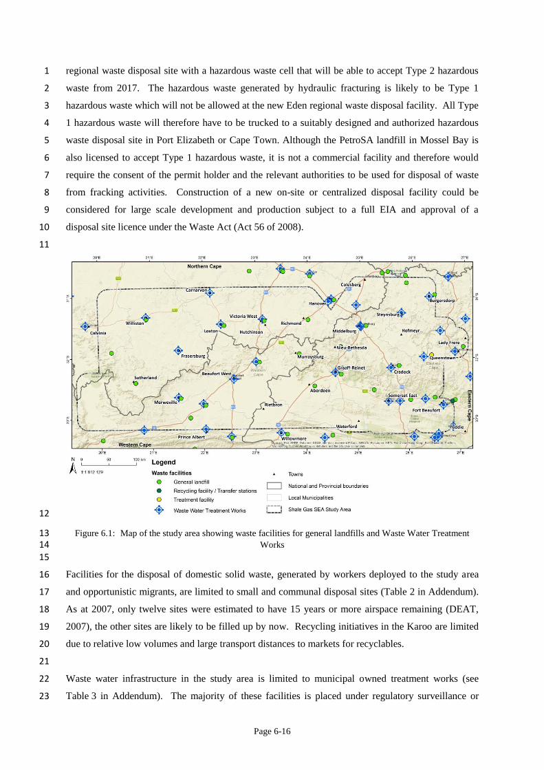
There are currently no specialized hazardous waste disposal or treatment facilities in the Karoo. The 13
spatial distribution of waste water treatment and solid waste disposal facilities in the study area is 14
illustrated in the map below. Eden District Municipality is in the process of building a Class B 15
Page 6-16
regional waste disposal site with a hazardous waste cell that will be able to accept Type 2 hazardous 1
waste from 2017. The hazardous waste generated by hydraulic fracturing is likely to be Type 1 2
hazardous waste which will not be allowed at the new Eden regional waste disposal facility. All Type 3
1 hazardous waste will therefore have to be trucked to a suitably designed and authorized hazardous 4
waste disposal site in Port Elizabeth or Cape Town. Although the PetroSA landfill in Mossel Bay is 5
also licensed to accept Type 1 hazardous waste, it is not a commercial facility and therefore would 6
require the consent of the permit holder and the relevant authorities to be used for disposal of waste 7
from fracking activities. Construction of a new on-site or centralized disposal facility could be 8
considered for large scale development and production subject to a full EIA and approval of a 9
disposal site licence under the Waste Act (Act 56 of 2008). 10
11
12
Figure 6.1: Map of the study area showing waste facilities for general landfills and Waste Water Treatment 13 Works 14
15
Facilities for the disposal of domestic solid waste, generated by workers deployed to the study area 16
and opportunistic migrants, are limited to small and communal disposal sites (Table 2 in Addendum). 17
As at 2007, only twelve sites were estimated to have 15 years or more airspace remaining (DEAT, 18
2007), the other sites are likely to be filled up by now. Recycling initiatives in the Karoo are limited 19
due to relative low volumes and large transport distances to markets for recyclables. 20
21
Waste water infrastructure in the study area is limited to municipal owned treatment works (see 22
Table 3 in Addendum). The majority of these facilities is placed under regulatory surveillance or 23
Page 6-17
requires immediate interventions (DWS, 2014). The ‘risk’ associated with municipal waste water 1
treatment facilities relates to design capacity (including the hydraulic loading into the receiving water 2
body), operational flow (exceeding, on or below capacity), and number of non-compliance trends in 3
terms of effluent quality (discharged into the receiving environment) and compliance or non-4
compliance in terms of technical skills (DWS, 2014). Waste water generated by shale gas exploration 5
and development will therefore have to be transported (trucked or piped) to suitable facilities further 6
afield or on-site treatment facilities will have to be established. The volumes during the exploration 7
phase (Phase 1) will be too small for pipelines and therefore transportation by truck will be the only 8
option. During exploitation (Phase 2) the ideal would be to have local (possibly mobile) waste water 9
treatment facilities to minimize fluid transport movement and distances in line with clause 117(a) of 10
the Petroleum Exploration and Production Regulations (RSA, 2015a). 11
6.3 Relevant legislation, regulation and practice 12
Applicable legislation to shale gas exploration and development in South Africa has been 13
promulgated by the Department of Mineral Resources, Department of Water and Sanitation and the 14
Department of Environmental Affairs. The Department of Mineral Resources is responsible for the 15
sustainable development of South Africa’s mineral and petroleum resources within the framework of 16
national environmental policy, norms and standards while promoting economic and social 17
development (RSA, 2002). The Department of Environmental Affairs is the lead agent for the 18
protection of the environment (RSA, 1998a) and waste management (RSA, 2008) while the 19
Department of Water Affairs is the public trustee of the nation’s water sources (RSA, 1998). 20
6.3.1 Mineral and Petroleum Resources Development Act, 2002 (Act 28 of 2002) 21
The objective of the Mineral Resources and Petroleum Development Act, 2002 (Act 28 of 2002) is 22
amongst other to “give effect to section 24 of the Constitution by ensuring that the nation’s mineral 23
and petroleum resources are developed in an orderly and ecologically sustainable manner while 24
promoting justifiable social and economic development” (RSA, 2002). 25
26
Page 6-18
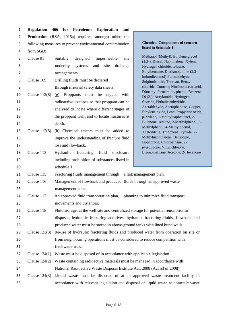
Regulation 466 for Petroleum Exploration and 1
Production (RSA, 2015a) requires, amongst other, the 2
following measures to prevent environmental contamination 3
from SGD: 4
Clause 91 Suitably designed impermeable site5
underlay systems and site drainage 6
arrangements. 7
Clause 109 Drilling fluids must be declared 8
through material safety data sheets. 9
Clause 112(8) (g) Proppants must be tagged with 10
radioactive isotopes so that proppant can be 11
analysed to locate where different stages of 12
the proppant went and to locate fractures at 13
depth. 14
Clause 112(8) (h) Chemical tracers must be added to 15
improve the understanding of fracture fluid 16
loss and flowback. 17
Clause 113 Hydraulic fracturing fluid disclosure 18
including prohibition of substances listed in 19
schedule 1. 20
Clause 115 Fracturing fluids management through a risk management plan. 21
Clause 116 Management of flowback and produced fluids through an approved waste 22
management plan. 23
Clause 117 An approved fluid transportation plan, planning to minimize fluid transport 24
movements and distances. 25
Clause 118 Fluid storage: at the well site and centralized storage for potential reuse prior to 26
disposal, hydraulic fracturing additives, hydraulic fracturing fluids, flowback and 27
produced water must be stored in above-ground tanks with lined bund walls. 28
Clause 123(3) Re-use of hydraulic fracturing fluids and produced water from operation on site or 29
from neighbouring operations must be considered to reduce competition with 30
freshwater uses. 31
Clause 124(1) Waste must be disposed of in accordance with applicable legislation. 32
Clause 124(2) Waste containing radioactive materials must be managed in accordance with 33
National Radioactive Waste Disposal Institute Act, 2008 (Act 53 of 2008). 34
Clause 124(3) Liquid waste must be disposed of at an approved waste treatment facility in 35
accordance with relevant legislation and disposal of liquid waste at domestic waste 36
Chemical Components of concern
listed in Schedule 1:
Methanol (Methyl), Ethylene glycol
(1,2-), Diesel, Naphthalene, Xylene,
Hydrogen chloride, toluene,
Ethylbenzene, Diethanolamine (2,2-
iminodiethanol) Formaldehyde,
Sulphuric acid, Thoreau, Benzyl
chloride, Cumene, Nitrilotriacetic acid,
Dimethyl formamide, phenol, Benzene,
Di (2-), Acrylamide, Hydrogen
fluoride, Phthalic anhydride,
Acetaldehyde, Acetophenone, Copper,
Ethylene oxide, Lead, Propylene oxide,
p-Xylene, 1-Methylnaphtalenel, 2-
Butanone, Aniline, 2-Methylphenol, 3-
Methylphenol, 4-Methylphenol,
Acetonitrile, Thiophene, Pyrrole, 2-
Methylnaphthalene, Benzidine,
Isophorone, Chloroethane, 2-
pyrrolidone, Vinyl chloride,
Bromomethane, Acetone, 2-Hexanone
Page 6-19
water treatment facilities must only take place after prior consultation with the 1
department responsible for water affairs. 2
Clause 124(4) Disposal to underground, including the use of re-injection disposal wells, is3
prohibited. 4
Clause 124(5) Discharge of hydraulic fracturing fluids, hydraulic fracturing flowback, and produced 5
water into surface water course is prohibited. 6
Clause 124(6) Annular disposal of drill cuttings or fluids is prohibited. 7
Clause 124(7) Drill cuttings and waste mud must be temporarily stored in above-ground tanks. 8
Clause 124(8) Solid waste generated during operations must be categorized and disposed of 9
accordingly at a licensed landfill site or treatment facility. 10
Clause 125 A waste management plan must be prepared and approved as part of the application 11
for Environmental Authorisation. 12
6.3.2 National Environmental Management Act, 1998 (Act 107 of 1998) 13
This act sets out the fundamental principles that apply to environmental decision making. The core 14
environmental principle is the promotion of ecologically sustainable development. Principles 15
referring to waste and pollution include: 16
That pollution and degradation of the environment are avoided or where they cannot be 17
altogether avoided, are minimised and remedied 18
That waste is avoided, or where it cannot be altogether avoided, minimized and re-used or 19
recycled where possible and otherwise disposed of in a responsible manner 20
Decisions must be taken in m open and transparent manner, and access to information must 21
be provided in accordance with the law 22
The cost of remedying pollution, environmental degradation and consequent adverse health 23
effects and of preventing, controlling or minimizing further pollution, environmental damage 24
or adverse health effects must be paid for by those responsible for harming the environment 25
26
Waste management activities that have, or are likely to have, a detrimental effect on the environment 27
as listed in Regulation 921 of 29 November 2013 (RSA, 2013c) are subject to the Environmental 28
Impact Assessment Regulations made under section 24(5) of the National Environmental 29
Management Act, 1998 as part of a waste management licence application under the National 30
Environmental Management: Waste Act, 2008. 31
32
Relevant regulations under NEMA: 33
Environmental Impact Assessment Regulations (Regulation 982 of 4 December 2014) 34
Page 6-20
Regulations pertaining to the financial provisions for prospecting, exploration, mining or 1
production operations (Regulation 1147 of 29 November 2015). 2
6.3.3 National Environmental Management: Waste Act, 2008 (Act 56 of 2008) 3
South Africa has an integrated pollution and waste management policy that is driven by a vision of 4
environmentally sustainable economic development by amongst other, preventing and minimising, 5
controlling and remediating pollution and waste to protect the environment from degradation (DEAT, 6
2000). Waste management in South Africa is informed by the waste management hierarchy which 7
outlines waste management options covering the lifecycle of waste, in descending order of priority: 8
waste avoidance (prevention and minimization), reuse and recycling, recovery, waste treatment and 9
disposal as last resort (DEA, 2012). 10
11
Waste legislation in South Africa is emerging and constantly changing. The National Environmental 12
Management: Waste Act, 2008 (NEMWA) is the first law in South Africa dedicated to waste and a 13
number of new strategies and regulations under this act are currently under development. 14
15
Waste management activities that may require a licence in terms of NEMWA are listed in Regulation 16
921 of 29 November 2013 (RSA, 2013c) and Regulation 633 of 24 July 2015 (RSA, 2015b). These 17
activities include: 18
Storage of general waste in lagoons and storage of hazardous waste in lagoons excluding 19
storage of effluent, waste water or sewage 20
Recycling or recovery of waste 21
Treatment of waste 22
Disposal of waste 23
Construction, expansion or decommissioning of facilities and associated structures and 24
infrastructure 25
Establishment or reclamation of a residue stockpile or residue deposit resulting from activities 26
which require a prospecting right or mining permit in terms of the Mineral and Petroleum 27
Resources Development Act, 2002 (Act 28 of 2002) 28
29
Depending on the size, handling capacity and the type of waste to be managed at the facility, a basic 30
assessment or full environmental impact assessment set out in the Environmental Impact Assessment 31
regulations under Section 24(5) of the National Environmental Management Act, 1998 (Act 107 of 32
1998) will be required as part of the licence application process. 33
34
Applicable regulations under NEMWA include: 35
Page 6-21
Waste Information regulations (Regulation 625 of 13 Aug 2012) 1
Waste Classification and Management Regulations (Regulation 634 of 23 Aug 2013) 2
National Norms and Standards for the Assessment of Waste for Landfill Disposal (Regulation 3
635 of 23 Aug 2013) 4
National Norms and Standards for Disposal of Waste to Landfill (Regulation 636 of 23 Aug 5
2013) 6
List of Waste Management Activities that have or are likely to have a detrimental impact on 7
the Environment (GN 921 of 29 Nov 2013) 8
National Norms and Standards for Storage of Waste (GN 926 of 29 Nov 2013) 9
Regulations regarding the planning and management of residue stockpiles and residue 10
deposits from a prospecting, mining, exploration or production operation (Regulation 632 of 11
24 July 2015) 12
Amendments to the list of waste management activities that have or are likely to have a 13
detrimental effect on the environment (Regulation 633 of 24 July 2015). 14
15
NEMWA and its regulations will not be able to 16
adequately deal with the waste from SGD. Site specific 17
waste management licences are required for each waste 18
activity requiring a licence. Multiple storage and 19
treatment facilities will potentially attract the need for 20
multiple licence applications each with a requirement 21
for an EIA at scoping or full assessment level which will 22
add cost and time delays in obtaining authorisations. 23
Waste classification regulation stipulate that waste must 24
be kept separate for purposes of classification, and must 25
be “re-classified within 30 days of modification to the 26
process or activity that generated the waste, changes in 27
raw materials or other inputs, or any other variation of 28
relevant factors” (RSA, 2013). 29
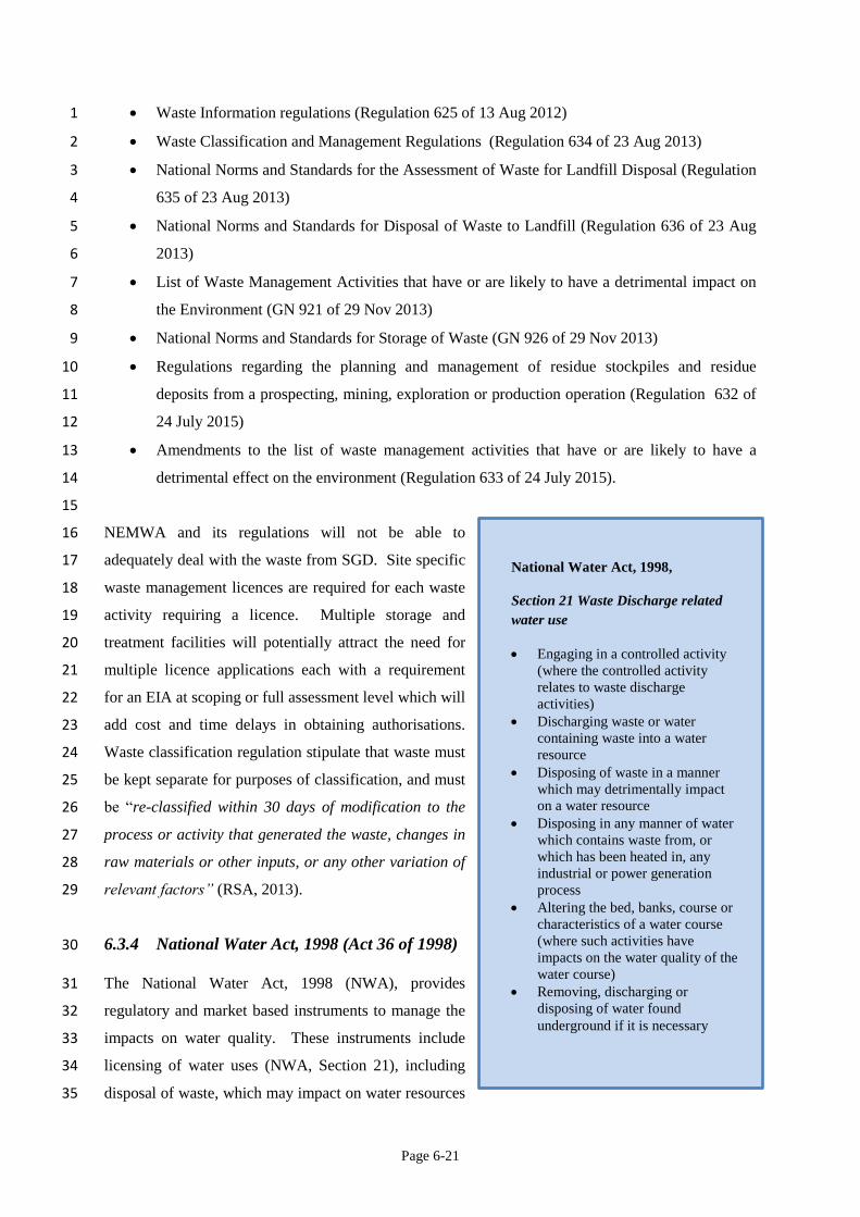
6.3.4 National Water Act, 1998 (Act 36 of 1998) 30
The National Water Act, 1998 (NWA), provides 31
regulatory and market based instruments to manage the 32
impacts on water quality. These instruments include 33
licensing of water uses (NWA, Section 21), including 34
disposal of waste, which may impact on water resources 35
National Water Act, 1998,
Section 21 Waste Discharge related
water use
Engaging in a controlled activity
(where the controlled activity
relates to waste discharge
activities)
Discharging waste or water
containing waste into a water
resource
Disposing of waste in a manner
which may detrimentally impact
on a water resource
Disposing in any manner of water
which contains waste from, or
which has been heated in, any
industrial or power generation
process
Altering the bed, banks, course or
characteristics of a water course
(where such activities have
impacts on the water quality of the
water course)
Removing, discharging or
disposing of water found
underground if it is necessary
Page 6-22
and waste discharge charges in line with the “polluter pays” principle (DWA, 2009). 1
2
Water used in excess of the limits specified in Schedule 1 and General Authorisation notices will 3
require a water use licence. The Minister may however dispense with the requirement for a licence 4
under the NWA (Section 22(3)) by issuing a Record of Decision which is then incorporated in the 5
waste licence issued under NEMWA. 6
7
Several water uses can be covered by one integrated water use licence. The integrated water use 8
licence will prescribe conditions for the management, monitoring and reporting relating to the water 9
use. An integrated water and waste management plan is a typical requirement of a water use licence. 10
11
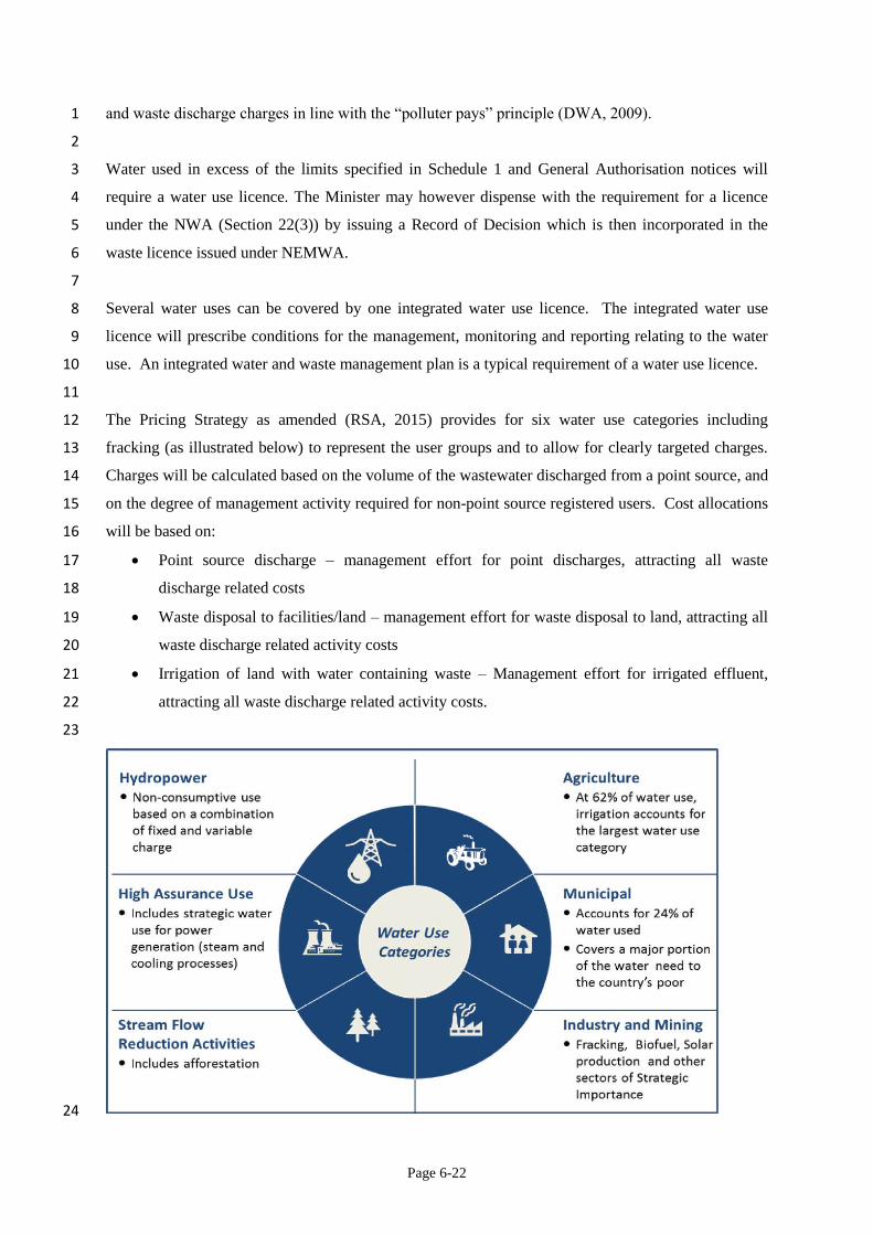
The Pricing Strategy as amended (RSA, 2015) provides for six water use categories including 12
fracking (as illustrated below) to represent the user groups and to allow for clearly targeted charges. 13
Charges will be calculated based on the volume of the wastewater discharged from a point source, and 14
on the degree of management activity required for non-point source registered users. Cost allocations 15
will be based on: 16
Point source discharge – management effort for point discharges, attracting all waste 17
discharge related costs 18
Waste disposal to facilities/land – management effort for waste disposal to land, attracting all 19
waste discharge related activity costs 20
Irrigation of land with water containing waste – Management effort for irrigated effluent, 21
attracting all waste discharge related activity costs. 22
23
24
Page 6-23
Figure 6.2: Water use categories as defined by the Pricing Strategy (RSA, 2015). 1 2
Relevant regulations under NWA: 3
Regulations on the use of water for mining and related activities aimed at the protection of 4
water resources (Regulation 77 of 12 February 2010). 5
6.3.5 National Nuclear Regulator Act, 1999 (Act 47 of 1999) 6
NORM waste will be regulated under this act. The National Nuclear Regulator document RD-004 7
Requirements Document on the Management of Radioactive waste associated with waste products 8
from facilities handling NORM (2007) describes how NORM waste must be managed. 9
6.3.6 National Road Traffic Act, 1996 (Act 93 of 1996) 10
Vehicles transporting dangerous goods (including hazardous waste) must adhere to SANS 10228 in 11
terms of identification and classification of goods and display the relevant signage. 12
In terms of Section 76 of the National Road Traffic Act, 1996 the following standards are deemed to 13
be regulations: 14
15
SANS 10228: Identifies and classifies each of the listed dangerous goods and substances and set out 16
information including the United Nations Number, the correct shipping name, hazard class assigned 17
and other information pertinent to the substance. 18
19
SANS 10229: Contains information on acceptable packaging for dangerous goods and substances and 20
also include requirements for the testing of packaging and the correct marking and labelling of 21
packages. 22
23
SANS 10230: Includes statutory vehicle inspection requirements for all vehicles conveying dangerous 24
goods. This code stipulates the safety aspects of both the vehicle and the goods containment. 25
Minimum inspection requirements by both in-house and outside agencies are listed. 26
27
SANS 10231: This code of practice prescribes the operation rules and procedures for transporting 28
Dangerous Goods and Hazardous Materials. It also includes the prescribed responsibilities of the 29
owner/operator of the dangerous goods vehicle. It outlines the information required and who will have 30
to supply information for the safe conveyance of dangerous goods. The requirements for the drafting 31
and formulating of an operational agreement are also specified. This code also requires the 32
owner/operator or vehicle to be registered as dangerous goods carrier. It is also prescribed that the 33
Page 6-24
owner operator has available adequate insurance cover for civil liability as well as pollution and 1
environmental rehabilitation cover in the event of an incident. 2
3
SANS 10232-1: 2007: This code includes details of new placarding requirements for vehicles 4
transporting dangerous goods and the individual or substance exempt quantities and the compatibility 5
requirements of mixed loads. Part 3 of this code contains information on the Emergency Response 6
Guides to be used in case of an incident or accident. 7
6.3.7 Disaster Management Act, 2002 (Act 57 of 2002) 8
This act provides for an integrated and coordinated disaster management policy that focuses on 9
preventing or reducing the risk of disasters (natural or human induced) mitigating the severity of 10
disasters, emergency preparedness, rapid and effective response to disasters and post-disaster 11
recovery. 12
6.4 Key potential impacts and their mitigation 13
Waste-generating pathways and handling options, include inter alia drilling fluids, drilling muds, 14
fracturing fluids, lubricating oils and greases, contaminated land (spills on-site), domestic waste, 15
sewage, construction waste etc. The expected volumes of waste generated during the different 16
scenarios for SGD in the Karoo is summarized in Chapter 1. Composition of the waste is important in 17
terms of classification and management of the waste - it is likely that most of the waste will be Type 1 18
hazardous waste. Disclosure of the hydraulic fracturing fluids in terms of chemical and concentration 19
by mass, as provided for in Clause 113 of Regulation 466 (RSA, 2015a) will assist in the accurate 20
classification of the waste. Prohibition of certain chemicals, as listed in Schedule 1 of Regulation 466 21
(RSA, 2015a), will limit the toxicity of the waste and thereby also the potential risk to the 22
environment and human health. The National Nuclear Regulator (NNR) is an important player for 23
low-level radio-active waste. 24
25
Municipalities will not be able to cope with additional waste loads (municipal solid waste and waste 26
water) at their facilities (landfill and sewage plants) (refer to Table 2 and 3 of the Addendum) due to 27
limited capacity and technical expertise in municipalities. Similarly, technical knowledge on the 28
specialized waste streams from SGD will need to be developed at national and provincial government 29
level to ensure informed decision making and enforcement of legislation. 30
31
Literature findings suggest that surface spills and leakages from holding ponds, tank battery systems 32
and transport of chemicals and waste materials are important routes of potential ground and surface 33
Page 6-25
water contamination from hydraulic fracturing activities (Grout and Grimshaw, 2012; Gross et al., 1
2013; Ziemkiewicz et al., 2014). Sources of spills at the wellsite include the drill rig and other 2
operating equipment, storage tanks, impoundments or pits, and leaks or blowouts at the wellhead 3
(Grout and Grimshaw, 2012). Leaks or spills may also occur during transportation (by truck or 4
pipeline) of materials and wastes to and from the well pad. The primary risk of uncontrolled releases 5
is generally to surface and groundwater resources (Grout and Grimshaw, 2012). Mitigation measures 6
to prevent pollution from spills include impermeable site underlay (Clause 91 Regulation 466) and 7
lined bund walls around storage tanks (Clause 118(3) Regulation 466) (RSA, 2015a). Constituents of 8
particular concern include benzene, toluene, ethylbenzene and xylene which, at sufficient doses, have 9
been associated with adverse human health effects (Osborn et al., 2011) and arsenic (Grout and 10
Grimshaw, 2012). These constituents of concerns have all been banned from being allowed as 11
additives to fracturing fluids (Schedule 1, Regulation 466) (RSA, 2015a). 12
13
Three important characteristics of an incident will determine the severity of its consequences – 14
volume, degree of containment and characteristics of the material (wastewater or waste) (Grout and 15
Grimshaw, 2012). It is therefore important to provide secondary containment for areas of fuel and 16
fracturing fluid chemicals storage, loading and unloading areas, and other key operational areas 17
(Grout and Grimshaw, 2012) including waste and waste water storage, treatment and disposal sites. 18
Such containment areas are already prescribed in Clause 118(3) of Regulation 466 (RSA, 2015a). 19
6.4.1 On-site storage 20
Maximising recycling and reuse of flowback water will reduce the amount chemicals and need for 21
clean water, but may increase the volume of waste and waste water to be stored on-site and may 22
increase the potential impacts. The mitigation measures to implement will include barrier and 23
containment systems such as impermeable site linings, bunding and using non-hazardous chemicals 24
where possible (Koppelman et al., 2012). All these measures are already prescribed in Regulation 25
466 (RSA, 2015a). Minimising design, construction and maintenance problems associated with: out-26
slope berm stability, uncontrolled groundwater seepage, geomembrane liner puncture, and tear 27
potential from improper site preparation and maintenance (Ziemkiewicz et al., 2014). In this regard, 28
Regulation 466 already prescribes above-ground storage tanks for all liquids, liquid waste, drill 29
cuttings and waste mud (RSA, 2015a). Secondary containment is a best management practice where 30
the tank sits within a tray-like structure with raised sides or berms such that materials released during 31
a tank rupture would be contained (Hammer and Van Briesen, 2012). Clause 118 of Regulation 466 32
stipulate a containment capacity to hold the volume of the largest container stored on-site plus 10% to 33
allow for precipitation, unless the container is equipped with individual secondary containment (RSA, 34
2015a). 35
Page 6-26
6.4.2 Liquid Waste Treatment 1
Liquid waste must be disposed of at an approved waste treatment facility in accordance with relevant 2
legislation (RSA, 2015a). The designated treatment works must have capacity to accept the load and 3
volume of waste water to be treated and must be duly authorized to receive the waste water from 4
fracking operations. Technologies must be appropriate for the quality of the waste water received and 5
it must be able to produce the required discharge quality. Waste water treatment technology choice 6
must be based on the degree and surety of removal of constituents required. Pre-treatment may also 7
be required depending on the treatment technology selected and the objectives to be met (DWAF, 8
2007). 9
10
It is expected that treatment of liquid waste could potentially be dealt with by modular, on-site, 11
containerized treatment facilities which are commercially available. Disposal of liquid waste at 12
domestic waste water treatment facilities must only take place after prior consultation with and 13
approval by the department responsible for water affairs (RSA, 2015a). 14
6.4.3 Off-site management and disposal 15
The current off-site disposal options for Type 1 hazardous wastes are limited to two licensed 16
commercial hazardous waste treatment facilities in Port Elizabeth and Cape Town and possibly the 17
private PetroSA hazardous waste landfill in Mossel Bay, provided that the relevant authorities and 18
landfill owner approve. Municipal wastewater treatment works in the study area do not have the 19
capacity or required technologies to treat the waste water from this process. It is therefore likely that 20
the waste water will also have to be trucked to a suitable off-site facility for treatment. Key potential 21
impacts from off-site management and disposal relates to the transport of the waste and waste water 22
by road or pipelines. Construction and maintenance deficiencies related to transport pipelines, or road 23
accidents if the waste or waste water is transported off site by road need to be mitigated (Ziemkiewicz 24
et al., 2014). Mitigation measures relating to pipelines will include proper design, construction and 25
placement of liquid transfer piping (Ziemkiewicz et al., 2014). It is also imperative that inadequate 26
capacity, treatment technologies and human resources at municipal treatment and disposal facilities be 27
addressed to ensure that additional loads of municipal solid waste and sewage can be handled 28
appropriately. 29
30
Whether to have central processing facilities or have those in conjunction with well pads, is a decision 31
that needs to be taken for each specific development, based on minimizing the overall negative impact 32
from the development (DNV, 2013). A centralised waste disposal facility for Type 1 hazardous waste 33
may be considered for full scale SGD. Site selection for establishing a disposal facility will involve 34
elimination of areas with associated fatal flaws, identification of candidate sites, based on site 35
Page 6-27
selection criteria, ranking of candidate sites and carrying out a feasibility study on the best option 1
(DWAF, 1998a). Site selection criteria include: 2
Economic criteria 3
Environmental criteria 4
Public acceptance criteria 5
6
Establishment and authorization of such a facility will require a full EIA, and meeting the design 7
requirements as outlined in the Norms and Standards for disposal of waste to landfill (Regulation 636 8
of 23 August 2013). 9
10
Processing facilities for solid waste and waste water must be designed and constructed to meet the 11
following criteria (DNV, 2013): 12
Design and construction will be in compliance with applicable standards 13
Design and construction will be to achieve effective utility according to anticipated life-time 14
and future development prospects 15
Processing facilities should as far as reasonably practicable be placed in the terrain in such a 16
way that any impact on vulnerable areas is minimized 17
Shall have area space and load bearing capacity to cater for processing systems and 18
equipment 19
Shall have appropriate spill control measured in place 20
6.4.4 Deep well injection 21
Deep well injection is a common disposal option in the USA, but due to the South African geology 22
and legal framework, it is not an option in South Africa. Regulation 466 for Petroleum Exploration 23
and Production (Clause 124(4)) prohibits disposal to underground, including the use of re-injection 24
disposal wells (RSA, 2015a). 25
6.4.5 Surface water discharge 26
Discharge of hydraulic fracturing fluids, hydraulic fracturing flowback, and produced water into a 27
water source is prohibited in terms of Clause 124(5) of Regulation 466 (RSA, 2015a). Treated 28
surplus water not recycled back into the operations may be discharged into surface water resources 29
provided that it meets quantity and quality limits stated in the applicable water use licence. There is a 30
risk of pollution of surface and ground water sources if the water quality does not meet the required 31
discharge standards. Residuals that are likely to be released to surface water include TDS and the 32
monovalent ions sodium, chloride, and bromide (Hammer and Van Briesen, 2012). Mitigation 33
Page 6-28
measures to ensure meeting water quality requirements will include alternative use options for the 1
waste water, treatment to prescribed standards, as specified in General Authorisations or applicable 2
licence, before discharge (this may require some form of pre-treatment as well) and regular 3
maintenance of treatment works. Regular water quality testing of effluent before discharge and 4
regular downstream water quality monitoring will also be required. Development of norms and 5
standards specific for discharge of treated shale gas flowback and produced water in the Karoo may 6
be required to ensure equal and adequate protection of all the water resources and associated 7
ecosystems in the study area. 8
6.4.6 Land application 9
Application of produced water to roads for dust control has several potential negative impacts 10
including: surface and groundwater deterioration, soil contamination, toxicity to soil and water biota, 11
toxicity to humans during and after application, air pollution from volatile dust suppressant 12
components, accumulation in soils, changes in hydrologic characteristics of soil, and impacts on 13
native flora and fauna populations (Hammer and Van Briesen, 2012). Areas with shallow ground 14
water resources may also be at risk of pollution if the quality of the water used in land application is 15
not sufficient. Mitigation of these negative impacts will be to treat the water to acceptable standards 16
before land application and continued monitoring. Norms and standards for land application of waste 17
water from SGD may be required to ensure adequate protection of the water resource and ecosystems 18
from potential impacts associated with land application of waste water. 19
6.4.7 Spills 20
The impact of spills of fracturing fluids (or waste water) onsite can be mitigated using established best 21
practices such as installing impermeable site linings, bunding and using non-hazardous chemicals 22
where possible (Koppelman et al., 2012). These requirements are already included in Regulation 466 23
of 3 June 2015. The impacts of spills resulting from transport incidents can be mitigated by 24
prescribing transport routes, limiting the transport distance as far as possible as envisaged by 25
Regulation 466 of 3 June 2015 and having spill response units on stand-by in the study area. 26
6.4.8 Residuals management 27
Regardless of the treatment options selected, residuals – the concentrated brines and solids containing 28
the chemicals removed from the produced water, and sludge – will be treated as a waste. Since 29
chemicals present in the residual wastes are present at higher concentrations than in the original 30
produced waters, careful management is essential. Solids and sludges generated in treatment plants 31
for produced water should be disposed of in landfills with adequate protection against the formation 32
Page 6-29
of subsequent brines in the leachate. The only mitigation measure for this waste will be to dispose of 1
the waste at a duly authorized landfill site, designed, constructed and operated in line with the 2
National Norms and Standards for disposal of waste to landfill. 3
6.5 Risk assessment 4
6.5.1 How risk is measured 5
Assessment of risk associated with waste and potential impacts on human health and the environment 6
must take into account all properties that are related to exposure within the environment (DWAF, 7
1998), such as: 8
Biodegradability 9
Persistence 10
Bioaccumulation 11
Chronic toxicity 12
Concentration 13
Production volume 14
High dispersion 15
Leakage to the environment 16
Risks associated with disposal of waste water sludges relate to sludge stability, disposal site design 17
and location, the constituents in the sludge and their hazardousness, possible groundwater pollution, 18
pollution of surface run-off as well as valuable land surface area taken up by surface disposal 19
(DWAF, 2007). 20
6.5.2 Limits of acceptable change 21
All waste water is treated to required standards to optimize reuse opportunities (on and off-site) 22
towards minimizing the requirement for fresh water resource use. Excess water that cannot be reused 23
is treated to a suitable quality for release back into a water resource without impacting negatively on 24
the receiving environment. 25
26
All waste generated as a result of SGD is managed in line with the waste management hierarchy and 27
the principles of integrated waste management to ensure sustainable development with due regard for 28
environmental protection. 29
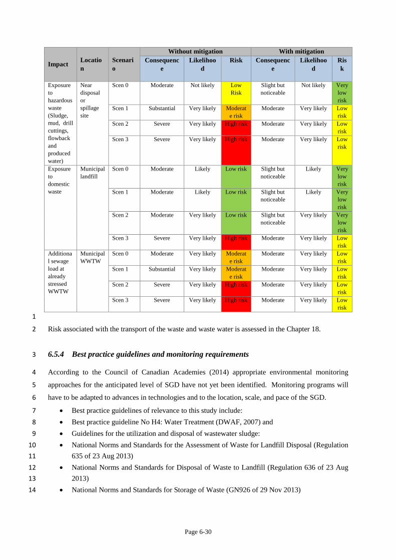
6.5.3 Risk Matrix 30
Table 6.6: Risk Matrix. 31
Page 6-30
Impact Locatio
n
Scenari
o
Without mitigation With mitigation
Consequenc
e
Likelihoo
d
Risk Consequenc
e
Likelihoo
d
Ris
k
Exposure
to
hazardous
waste
(Sludge,
mud, drill
cuttings,
flowback
and
produced
water)
Near
disposal
or
spillage
site
Scen 0 Moderate Not likely Low
Risk
Slight but
noticeable
Not likely Very
low
risk
Scen 1 Substantial Very likely Moderat
e risk
Moderate Very likely Low
risk
Scen 2 Severe Very likely High risk Moderate Very likely Low
risk
Scen 3 Severe Very likely High risk Moderate Very likely Low
risk
Exposure
to
domestic
waste
Municipal
landfill
Scen 0 Moderate Likely Low risk Slight but
noticeable
Likely Very
low
risk
Scen 1 Moderate Likely Low risk Slight but
noticeable
Likely Very
low
risk
Scen 2 Moderate Very likely Low risk Slight but
noticeable
Very likely Very
low
risk
Scen 3 Severe Very likely High risk Moderate Very likely Low
risk
Additiona
l sewage
load at
already
stressed
WWTW
Municipal
WWTW
Scen 0 Moderate Very likely Moderat
e risk
Moderate Very likely Low
risk
Scen 1 Substantial Very likely Moderat
e risk
Moderate Very likely Low
risk
Scen 2 Severe Very likely High risk Moderate Very likely Low
risk
Scen 3 Severe Very likely High risk Moderate Very likely Low
risk
1
Risk associated with the transport of the waste and waste water is assessed in the Chapter 18. 2
6.5.4 Best practice guidelines and monitoring requirements 3
According to the Council of Canadian Academies (2014) appropriate environmental monitoring 4
approaches for the anticipated level of SGD have not yet been identified. Monitoring programs will 5
have to be adapted to advances in technologies and to the location, scale, and pace of the SGD. 6
Best practice guidelines of relevance to this study include: 7
Best practice guideline No H4: Water Treatment (DWAF, 2007) and 8
Guidelines for the utilization and disposal of wastewater sludge: 9
National Norms and Standards for the Assessment of Waste for Landfill Disposal (Regulation 10
635 of 23 Aug 2013) 11
National Norms and Standards for Disposal of Waste to Landfill (Regulation 636 of 23 Aug 12
2013) 13
National Norms and Standards for Storage of Waste (GN926 of 29 Nov 2013) 14
Page 6-31
Minimum Requirements for the Monitoring of Water Quality at Waste Management 1
Facilities. (DWAF, 1998b) 2
6.5.4.1 Best Practice Guideline No H4: Water Treatment 3
These guidelines (DWAF, 2007) outline a water treatment plant evaluation and selection process to 4
assist decision makers in selecting an appropriate technology for their specific requirements. It 5
describes in a fair amount of detail the differences between different treatment technologies including 6
benefits and constraints of each technology option. The guidelines also touch on the characteristics of 7
residue streams and provide some guidance on possible disposal options for the residue streams. 8
Costs associated with the disposal of residues/sludges include disposal costs (based on volume and 9
nature) and transportation cost (transportation distance to disposal site). 10
6.5.4.2 Guidelines for the Utilisation and Disposal of Wastewater Sludge 11
The development of the sludge guidelines (Herselman and Snyman, 2007) was commissioned by the 12
Water Research Commission to encourage the beneficial use of wastewater sludge. It is however 13
recognized that beneficial use of waste water sludge is not always feasible. A separate Guideline 14
Volume dealing with each of the management options were therefore developed as follows: 15
Volume 1: Selection of management options 16
Volume 2: Requirements for the agricultural use of sludge 17
Volume 3: Requirements for the on-site and off-site disposal of sludge 18
Volume 4: Requirements for the beneficial use of sludge 19
Volume 5: Requirements for thermal sludge management practices and for commercial 20
products containing sludge 21
22
The quality and classification of the sludge is the determining factor in selecting the best management 23
option. 24
6.5.4.3 National Norms and Standards for Assessment of Waste for Landfill Disposal 25
The assessment of waste for the purpose of disposal to landfill requires a full chemical analysis of the 26
waste and laboratory analysis to determine the total concentrations (TC) and leachable concentrations 27
(LC) of the elements and chemical substances contained in the waste (RSA, 2013a) . The TC and LC 28
limits must then be compared to the threshold limits specified in the norms and standards to determine 29
the type of waste. All analyses must be done at accredited laboratories. 30
Page 6-32
6.5.4.4 Norms and Standards for Disposal of Waste to Landfill 1
The norms and standards for disposal of waste provides for four different classes of landfills based on 2
their containment barrier designs parameters. Waste acceptance criteria for landfill is based on the 3
Type of waste and the class of landfill as outlined in Clause 4 of Regulation 636 (RSA, 2013b). 4
6.5.4.5 National Norms and Standards for Storage of Waste 5
These standards apply to any person who store general or hazardous waste in a waste storage facility 6
irrespective of whether a waste management licence is required or not. Waste storage facilities must 7
be registered with the competent authority. Location of hazardous waste storage facilities must be 8
within an industrial demarcated zone or must have a buffer zone of at least 100 meter unless there is a 9
prescribed buffer zone by the relevant municipality and must be located in areas accessible to 10
emergency response personnel and equipment (RSA, 2013d). 11
12
Liquid waste storage areas must have firm, impermeable, chemical resistant floors and a roof. Liquid 13
waste containers that are not stored under a roof must be coated to prevent direct sunlight and rain 14
from getting into contact with the waste. There are also requirements for liquid storage areas to be 15
surrounded by an interception trench with a sump and a secondary containment system (i.e. bund, drip 16
tray) (RSA, 2013d). 17
18
Hazardous waste storage facilities must have impermeable and chemical resistant floors (RSA, 19
2013d). 20
21
These norms and standards also prescribe access control and notices as well as operational 22
requirements. There are also prescribed minimum requirements for above ground waste storage tanks 23
(Clause 11) (RSA, 2013d). 24
6.5.4.6 Minimum Requirements for Monitoring of Water Quality at Waste Management 25
Facilities 26
Acknowledging the uniqueness of the South African groundwater systems, the Minimum 27
Requirements were developed to ensure coordinated and meaningful water quality monitoring by 28
applying the principle of best available technology, not entailing excessive cost (DWAF, 1998b). It is 29
a minimum requirement that a risk assessment, to determine the risk of water becoming polluted, be 30
performed at all waste sites before the installation of a monitoring system. This serves to ensure that 31
the design of the monitoring system is adequate and the risk assessment methodology to follow is 32
prescribed in the report (DWAF, 1998b). 33
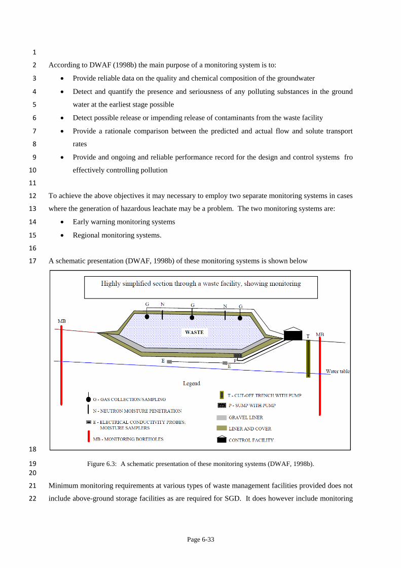
Page 6-33
1
According to DWAF (1998b) the main purpose of a monitoring system is to: 2
Provide reliable data on the quality and chemical composition of the groundwater 3
Detect and quantify the presence and seriousness of any polluting substances in the ground 4
water at the earliest stage possible 5
Detect possible release or impending release of contaminants from the waste facility 6
Provide a rationale comparison between the predicted and actual flow and solute transport 7
rates 8
Provide and ongoing and reliable performance record for the design and control systems fro 9
effectively controlling pollution 10
11
To achieve the above objectives it may necessary to employ two separate monitoring systems in cases 12
where the generation of hazardous leachate may be a problem. The two monitoring systems are: 13
Early warning monitoring systems 14
Regional monitoring systems. 15
16
A schematic presentation (DWAF, 1998b) of these monitoring systems is shown below 17
18
Figure 6.3: A schematic presentation of these monitoring systems (DWAF, 1998b). 19 20
Minimum monitoring requirements at various types of waste management facilities provided does not 21
include above-ground storage facilities as are required for SGD. It does however include monitoring 22
Page 6-34
requirements for general and hazardous waste disposal facilities and sewage sludge as indicated 1
below. 2
3
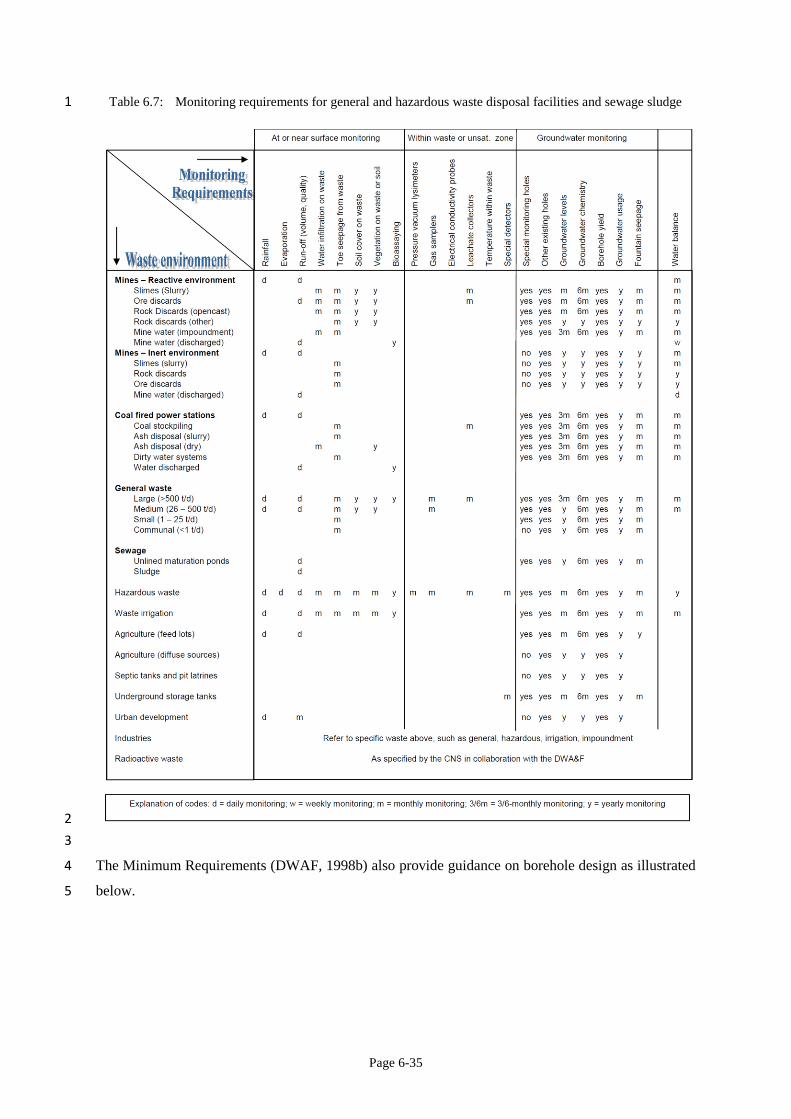
Page 6-35
Table 6.7: Monitoring requirements for general and hazardous waste disposal facilities and sewage sludge 1
2
3
The Minimum Requirements (DWAF, 1998b) also provide guidance on borehole design as illustrated 4
below. 5
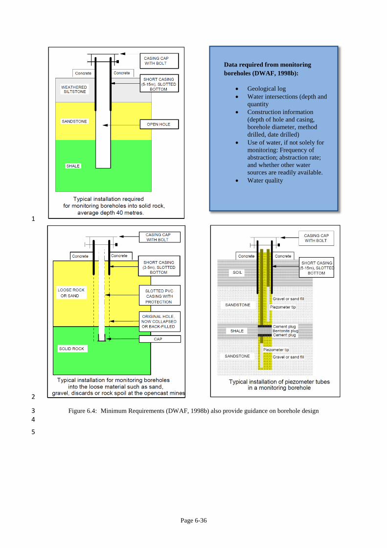
Page 6-36
1
2
Figure 6.4: Minimum Requirements (DWAF, 1998b) also provide guidance on borehole design 3 4
5
Data required from monitoring
boreholes (DWAF, 1998b):
Geological log
Water intersections (depth and
quantity
Construction information
(depth of hole and casing,
borehole diameter, method
drilled, date drilled)
Use of water, if not solely for
monitoring: Frequency of
abstraction; abstraction rate;
and whether other water
sources are readily available.
Water quality
Page 6-37
6.6 Topics on which information is inadequate for decision-making 1
Suitable sites for waste water treatment and on-site disposal of waste must be identified should SGD 2
go ahead. Detail on the composition of the wastes will be required to inform site selection, design 3
requirements of these facilities as well as the technology choices to consider. 4
5
6.7 References 6
Amec, 2013. Strategic Environmental Assessment for futher onshore oil and gas licensing: 7
Environmental Report. Department of Energy and Climate Change, United Kingdom. 8
Broderick J, Wood R, Gilbert P, Sharmina M and Anderson K. 2011 Shale gas: an updated 9
assessment of environmental and climate impacts. A report commissioned by The Co-operative 10
and undertaken by researchers at the Tyndall Centre, Univeristy of Manchester. 11
Council of Canadian Academies, 2014. Environmental Impacts of Shale Gas Extraction in Canada. 12
Ottawa (ON): The Expert Panel on Harnessing Science and Technology to Understand the 13
Environmental Impacts of Shale Gas Extraction, Council of Canadian Academies. 14
DEAT, 2000. White Paper on Integrated Pollution and Waste Management for South Africa: A policy 15
on Pollution Prevention, Waste Minimisation, Impact Management and Remediation. 16
Department of Environmental Affairs and Tourism, Pretoria. 17
DEAT, 2007. Disposal site census report of unauthorised disposal sites in South Africa. Department 18
of Environmental Affairs and Tourism, Pretoria. 19
DEA, 2012. National Waste Management Strategy. GN 344 Government Gazette 35306 of 4 May 20
2012. 21
DiGiulio DC, Wilkin RT, Miller C and Oberley G. 2011. Draft: Investigation of ground water 22
contamination near Pavillion, Wyoming, US. Environmental Protection Agency: Oklahoma. 23
DNV (Det Norske Veritas AS) 2013. Risk Management of Shale Gas Development and Operations. 24
Recommended Practice DNV-RP-U301 January 2013. 25
DWA, 2009. Water for Growth and Development Framework. Available online at 26
https://www.dwa.gov.za/wfgd/documents/wfgdv6nov21.pdf 27
DWAF, 1998. Waste Management Series. Minimum Requirements for the Handling, Classification 28
and Disposal of hazardous waste. Department of Water Affairs and Forestry, Pretoria. 29
Page 6-38
DWAF, 1998a. Waste Management Series. Minimum Requirements for Waste Disposal by Landfill. 1
Department of Water Affairs and Forestry, Pretoria. 2
DWAF, 1998b. Waste Management Series. Minimum Requirements for Water Monitoring at Waste 3
Management Facilities. Department of Water Affairs and Forestry, Pretoria 4
DWAF, 2007. Best Practice Guideline No. H4: Water Treatment. Department of Water Affairs and 5
Forestry, Pretoria. 6
DWS 2014. 2014 Green Drop Progress Report. Department of Water and Sanitation, Pretoria. 7
Gross SA, Avens HJ, Banducci AM, Sahmel J, Panko JM and Tvermoes BE. 2013. Analysis of BTEX 8
groundwater concertations from surface spills associated with hydraulic fracturing operations. 9
Journal of the Air and Waste Management Association 63:424-432. 10
Grout CG and Grimshaw TW, 2012. Fact-based regulation for environmental protection in shale gas 11
development. Energy Institute, University of Texas: Austin. 12
Hammer R and Van Briesen J. 2012. In Fracking’s Wake: New rules are needed to protect our health 13
and environment from contaminated waste water. NRDC Document, May 2012 D:12-05-A. 14
Herselman JE and Snyman HG, 2007. Guidelines for the Utilisation and Disposal of Wastewater 15
Sludge. Water Research Commission, Pretoria. 16
Kiboub, FZ. 2011. Oil and gas production waste: Case study, best available technologies and shared 17
lessons. Norwegian University of Science and Technology, Trondheim. 18
Koppelman B, Walker A and Woods E. 2012. Shale gas extraction in the UK: A review of hydraulic 19
fracturing. The Royal Society and the Royal Academy of Engineering, 2012. 20
Lee R, Seright, Hightower M, Sattler A, Cather M, McPherson B, Wrotenbery L, Martin A and 21
Whitworth M. 2002. Strategies for Produced water handling in New Mexico. 22
OGP 2009. Guidelines for waste management with special focus on areas with limited infrastructure. 23
Report No 413 rev 1.1 September 2008 (updated March 2009) International Association of Oil 24
and Gas Producers, United Kingdon. 25
Osborn, S. G., Vengosh, A., Warner, N. R., & Jackson, R. B. 2011a. Methane contamination of 26
drinking water accompanying gas-well drilling and hydraulic fracturing. Proceedings of the 27
National Academy of Sciences of the United States of America, 108(20), 8172–8176. 28
http://doi.org/10.1073/pnas.1109270108 29
Page 6-39
RSA, 1998. National Water Act, 1998 (Act 36 of 1998). Government Gazatte 19182, Notice 1091 of 1
26 August 1998. 2
RSA, 1998a. National Environmental Management Act, 1998 (Act 107 of 1998). Government Gazette 3
19519, Notice 1540 of 27 November 1998. 4
RSA, 2002. Mineral and Petroleum Resources Development Act, 2002 (Act 28 of 2002). Government 5
Gazette 23922, Notice 448 of 10 October 2002. 6
RSA, 2008. National Environmental Management: Waste Act, 2008. (Act 56 of 2008) Government 7
Gazette 32000, Notice 278 of 10 March 2009. 8
RSA, 2013. Waste Classification and Management Regulations. Government Gazette 36784, 9
Regulation 634 of 23 August 2013. 10
RSA, 2013a. National Norms and Standards for the assessment of waste for landfill disposal. 11
Government Gazette 36784, Regulation 635 of 23 August 2013. 12
RSA, 2013b. National Norms and Standards for disposal of waste to landfill. Government Gazette 13
36784 Regulation 636 of 23 August 2016. 14
RSA, 2013c. List of Waste management Activities that have or are likely to have a detrimental effect 15
on the environment. Government Gazette 37083, Regulation 921 of 29 November 2013. 16
RSA, 2013d. National Norms and Standards for the Storage of Waste. Government Gazette 37088 17
Regulation 926 of 29 November 2013. 18
RSA, 2014. National Environmental Management: Waste Amendment Act, 2014 (Act 26 of 2014) 19
Government Gazette 37714, Notice 449 of 2 June 2014. 20
RSA, 2015. Revision of the pricing strategy for water use charges in terms of section 56(1) of the 21
National Water Act, 1998. Government Gazette 39411, Notice 1154 of 13 November 2015. 22
RSA, 2015a. Mineral and Petroleum Resources Development Act, 2002 (Act 28 of 2002): 23
Regulations for Petroleum Exploration and Production. Government Gazette 38855, Regulation 24
466 of 3 June 2015. 25
RSA, 2015b. Amendments to the List of Waste Management Activities that have, or are likely to 26
have, a Detrimental Impact on the Environment. Government Gazette 39020, Regulation 633 of 27
24 July 2015. 28
Page 6-40
Shaffer DL, Chavez LHA, Ben-Sasson M, Castrillon SR-V, Yip, NY and Elimelech M. 2013. 1
Desalination and reuse of high-salinity shale gas produced water: Drivers, Technologies, and 2
future directions Environmental Science and Technology 47: 9569-9583. 3
Shariq L. 2013. Uncertainties associated with the reuse of treated hydraulic fracturing wastewater for 4
crop irrigation. Environmental Science and technology 47:2435-2436. 5
Veil J. 2015. U.S. Produced water volumes management practices in 2012. Prepared for the Ground 6
Water Protection Council, April 2015. 7
Zhang X, Sun AY and Duncan IJ. 2016. Shale gas wastewater management under uncertainty. 8
Journal of Environmental Management 165: 188-198. 9
Ziemkiewicz PF, Quaranta JD, Darnell A and Wise R. 2014. Exposure pathways related to shale gas 10
development and procedures for reducing environmental and public risk. Journal of Natural 11
Gas Science and Engineering 16: 77-84. 12
13
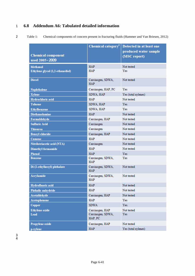
Page 6-41
6.8 Addendum A6: Tabulated detailed information 1
Table 1: Chemical components of concern present in fracturing fluids (Hammer and Van Briesen, 2012) 2
3 4
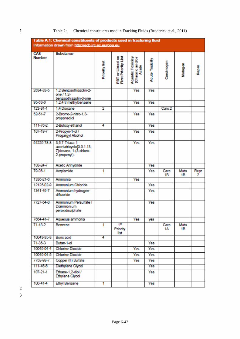
Page 6-42
Table 2: Chemical constituents used in Fracking Fluids (Broderick et al., 2011) 1
2
3
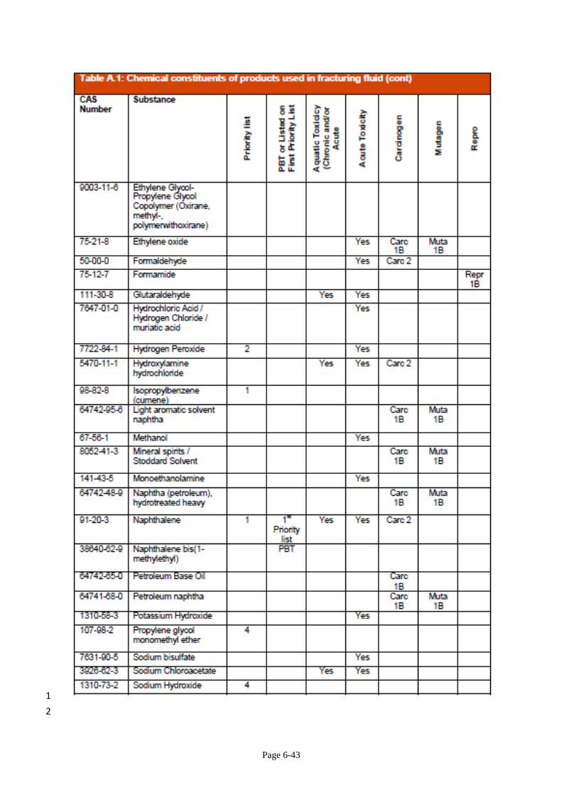
Page 6-43
1
2
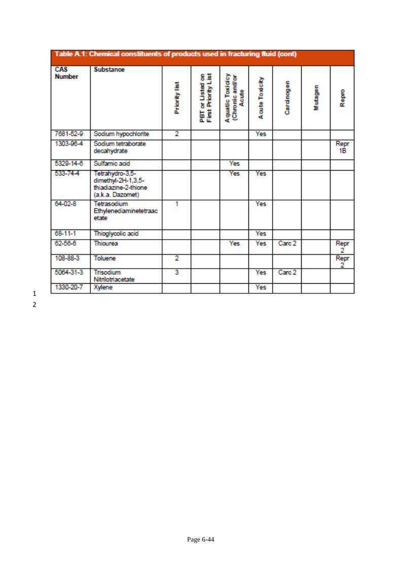
Page 6-44
1
2
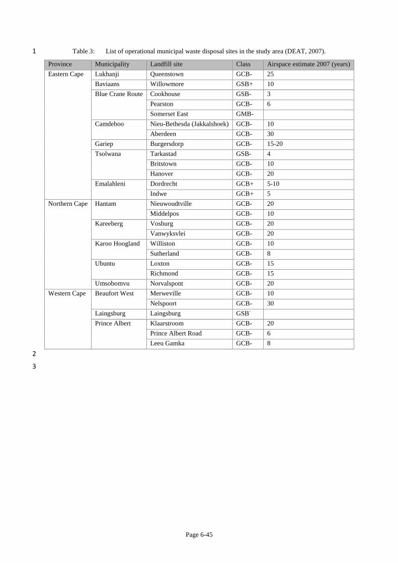
Page 6-45
Table 3: List of operational municipal waste disposal sites in the study area (DEAT, 2007). 1
Province Municipality Landfill site Class Airspace estimate 2007 (years)
Eastern Cape Lukhanji Queenstown GCB- 25
Baviaans Willowmore GSB+ 10
Blue Crane Route Cookhouse GSB- 3
Pearston GCB- 6
Somerset East GMB-
Camdeboo Nieu-Bethesda (Jakkalshoek) GCB- 10
Aberdeen GCB- 30
Gariep Burgersdorp GCB- 15-20
Tsolwana Tarkastad GSB- 4
Britstown GCB- 10
Hanover GCB- 20
Emalahleni Dordrecht GCB+ 5-10
Indwe GCB+ 5
Northern Cape Hantam Nieuwoudtville GCB- 20
Middelpos GCB- 10
Kareeberg Vosburg GCB- 20
Vanwyksvlei GCB- 20
Karoo Hoogland Williston GCB- 10
Sutherland GCB- 8
Ubuntu Loxton GCB- 15
Richmond GCB- 15
Umsobomvu Norvalspont GCB- 20
Western Cape Beaufort West Merweville GCB- 10
Nelspoort GCB- 30
Laingsburg Laingsburg GSB-
Prince Albert Klaarstroom GCB- 20
Prince Albert Road GCB- 6
Leeu Gamka GCB- 8
2
3
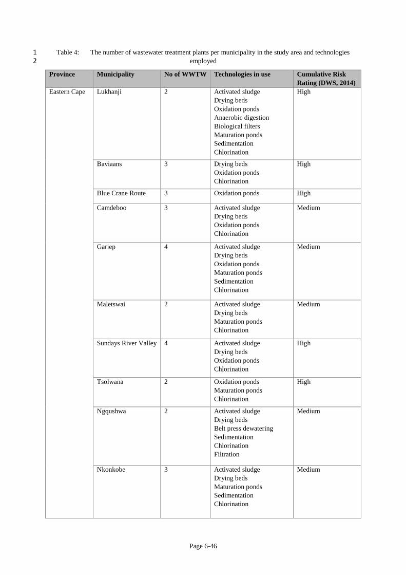
Page 6-46
Table 4: The number of wastewater treatment plants per municipality in the study area and technologies 1 employed 2
Province Municipality No of WWTW Technologies in use Cumulative Risk
Rating (DWS, 2014)
Eastern Cape Lukhanji 2 Activated sludge
Drying beds
Oxidation ponds
Anaerobic digestion
Biological filters
Maturation ponds
Sedimentation
Chlorination
High
Baviaans 3 Drying beds
Oxidation ponds
Chlorination
High
Blue Crane Route 3 Oxidation ponds High
Camdeboo 3 Activated sludge
Drying beds
Oxidation ponds
Chlorination
Medium
Gariep 4 Activated sludge
Drying beds
Oxidation ponds
Maturation ponds
Sedimentation
Chlorination
Medium
Maletswai 2 Activated sludge
Drying beds
Maturation ponds
Chlorination
Medium
Sundays River Valley 4 Activated sludge
Drying beds
Oxidation ponds
Chlorination
High
Tsolwana 2 Oxidation ponds
Maturation ponds
Chlorination
High
Ngqushwa 2 Activated sludge
Drying beds
Belt press dewatering
Sedimentation
Chlorination
Filtration
Medium
Nkonkobe 3 Activated sludge
Drying beds
Maturation ponds
Sedimentation
Chlorination
Medium
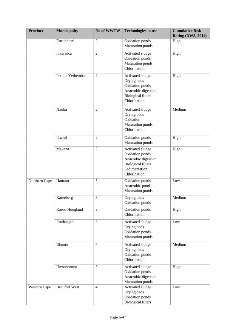
Page 6-47
Province Municipality No of WWTW Technologies in use Cumulative Risk
Rating (DWS, 2014)
Emalahleni 2 Oxidation ponds
Maturation ponds
High
Inkwanca 2 Activated sludge
Oxidation ponds
Maturation ponds
Chlorination
High
Inxuba Yethemba 2 Activated sludge
Drying beds
Oxidation ponds
Anaerobic digestion
Biological filters
Chlorination
High
Nxuba 2 Activated sludge
Drying beds
Oxidation
Maturation ponds
Chlorination
Medium
Ikwezi 2 Oxidation ponds
Maturation ponds
High
Makana 3 Activated sludge
Oxidation ponds
Anaerobic digestion
Biological filters
Sedimentation
Chlorination
High
Northern Cape Hantam 5 Oxidation ponds
Anaerobic ponds
Maturation ponds
Low
Kareeberg 3 Drying beds
Oxidation ponds
Medium
Karoo Hoogland 3 Oxidation ponds
Chlorination
High
Emthanjeni 3 Activated sludge
Drying beds
Oxidation ponds
Maturation ponds
Low
Ubuntu 3 Activated sludge
Drying beds
Oxidation ponds
Chlorination
Medium
Umsobomvu 3 Activated sludge
Oxidation ponds
Anaerobic digestion
Maturation ponds
High
Western Cape Beaufort West 4 Activated sludge
Drying beds
Oxidation ponds
Biological filters
Low
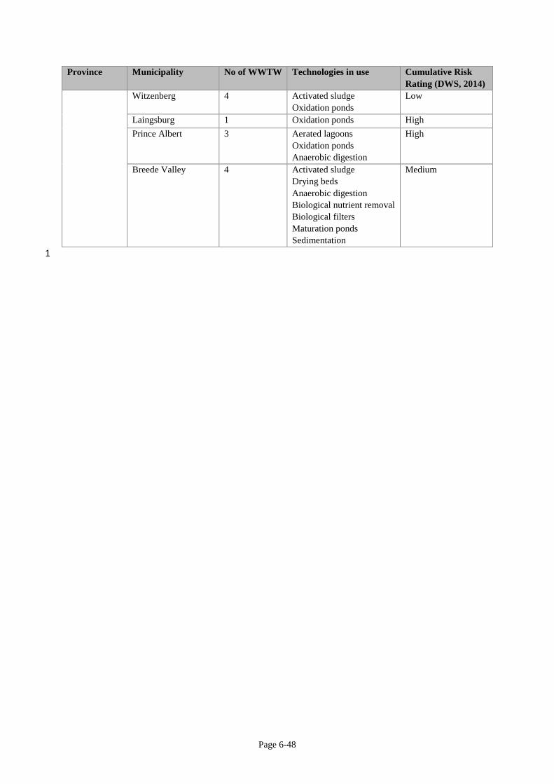
Page 6-48
Province Municipality No of WWTW Technologies in use Cumulative Risk
Rating (DWS, 2014)
Witzenberg 4 Activated sludge
Oxidation ponds
Low
Laingsburg 1 Oxidation ponds High
Prince Albert 3 Aerated lagoons
Oxidation ponds
Anaerobic digestion
High
Breede Valley
4 Activated sludge
Drying beds
Anaerobic digestion
Biological nutrient removal
Biological filters
Maturation ponds
Sedimentation
Medium
1