Embed Size (px)
Citation preview

CHAPTER 6
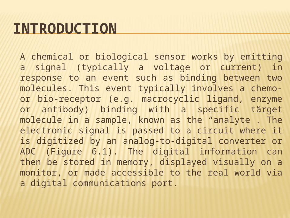
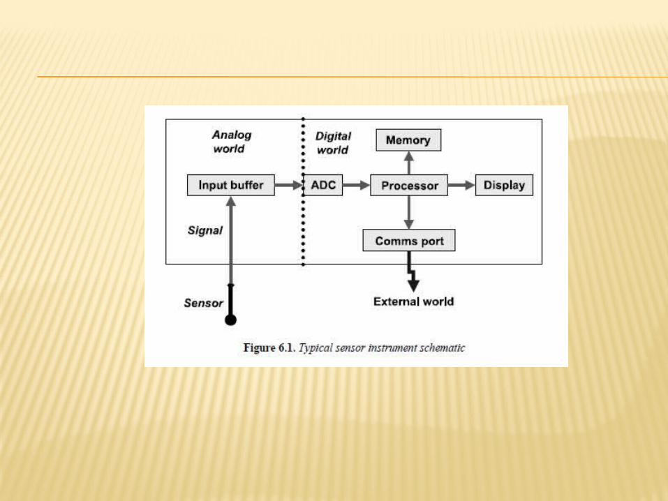
INTRODUCTIONA chemical or biological sensor works by emitting a signal (typically a voltage or current) in response to an event such as binding between two molecules. This event typically involves a chemo- or bio-receptor (e.g. macrocyclic ligand, enzyme or antibody) binding with a specific target molecule in a sample, known as the “analyte”. The electronic signal is passed to a circuit where it is digitized by an analog-to-digital converter or ADC (Figure 6.1). The digital information can then be stored in memory, displayed visually on a monitor, or made accessible to the real world via a digital communications port.
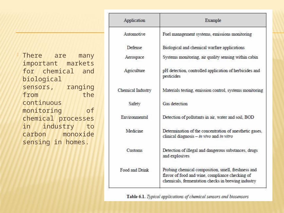
There are many important markets for chemical and biological sensors, ranging from the continuous monitoring of chemical processes in industry to carbon monoxide sensing in homes.
A chemical sensor may be defined as “a device, consisting of a transducer and a chemically sensitive film/membrane, that generates a signal related to the concentration of a particular species in a given sample”.
A biological sensor (a biosensor) may be defined as “a device, consisting of a transducer and a film/membrane that contains a biological material e.g. an enzyme or an antibody, that generates a signal related to the concentration of a particular species in a given sample”
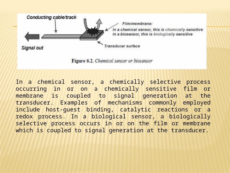
In a chemical sensor, a chemically selective process occurring in or on a chemically sensitive film or membrane is coupled to signal generation at the transducer. Examples of mechanisms commonly employed include host-guest binding, catalytic reactions or a redox process. In a biological sensor, a biologically selective process occurs in or on the film or membrane which is coupled to signal generation at the transducer.
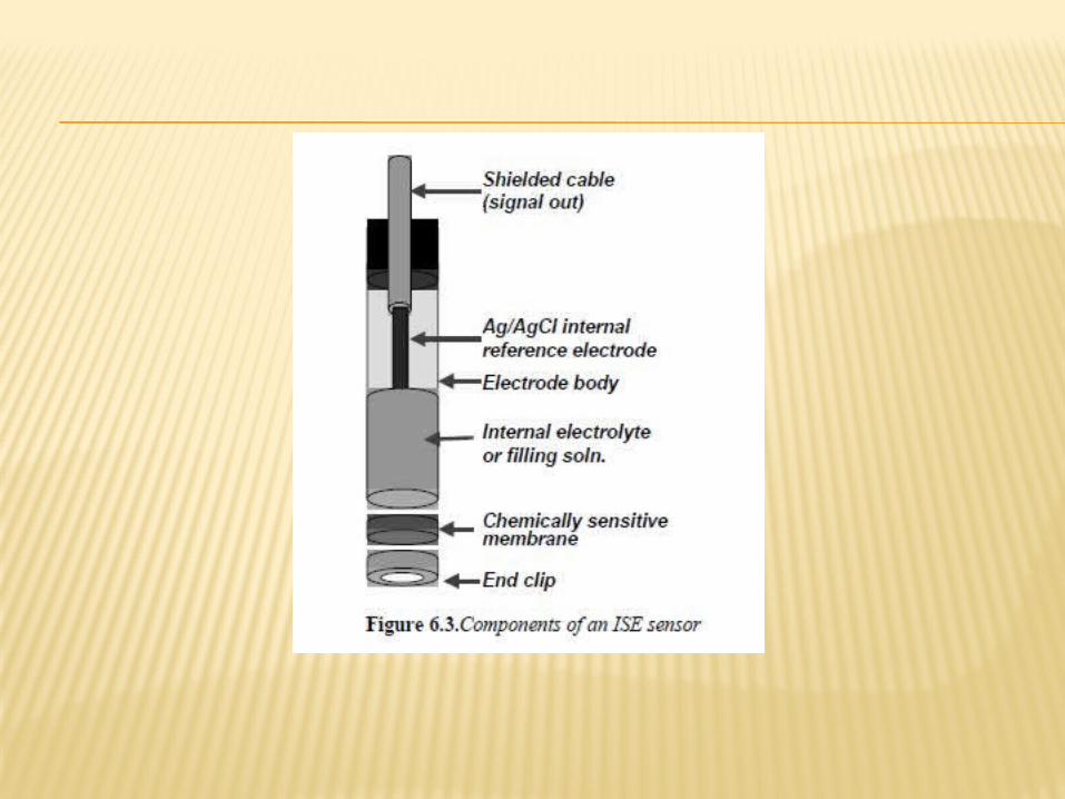
One of the best known examples of a chemical sensor is the ion-selective electrode (ISE). These electrochemical sensors typically employ a silver-silver chloride (Ag/AgCl) wire as the transducer, a membrane at which the chemorecognition signal generation occurs, and an internal electrolyte to electronically couple the membrane and the Ag/AgCl wire.
For example, many cation-selective electrodes are based on highly plasticized poly(vinyl) chloride (PVC) membranes containing immobilized ion-receptors. When exposed to a sample containing the analyte, selective binding of the target cations occurs leading to a change in the membrane potential, which can be detected at the Ag/AgCl wire.
PERFECT SENSOR– rapid (instantaneous) response;– signal-specific rather than signal-selective response for the
parameter/species of interest; – be small, light, robust and easily linked to instruments and/or computers; – able to be worn or used/left in remote locations (measurements at point
of need);– cost nothing to make and operate; never break or malfunction;– zero energy consumption;– compatible with automated fabrication techniques;– no calibration required;– no reagents needed (reagentless assays).
Obviously, this perfect sensor does not exist, and never will, but it is vital that chemical sensors and biosensors meet user demands for devices that are as close to the ideal reagentless, calibration free, reliable devices as possible.
WHAT IS INVOLVED IN DEVELOPING A SENSOR?
It becomes necessary to design sensors which are as specific as possible for an analyte so that the sensor will discriminate against any interferents present. This is achieved using molecular recognition, where the sensor contains what is called a host molecule or chemoreceptor that will selectively bind the target analyte (which is quite often referred to as a guest). Once a suitable host-guest chemistry has been found, the host molecules need to be immobilized or incorporated in some way into the sensor. Finally, a means of signaling that the binding/recognition event has occurred has to be found (transduction).
MOLECULAR RECOGNITION Key requirements for molecular recognition is the existence of
preorganized groups within the host molecule that can selectively enclose or bind the guest ion (single atom) or molecule.
In designing host molecules to be used in a sensor, the following criteria should be considered:
– The host molecule should be stable to the conditions in which it will be used.
– It must be able to selectively bind the target analyte in the sample.– It must be capable of being immobilized in a film/membrane which
is contacted with the sample.– It must signal that a host-guest binding event has occurred.– Ideally it should release the analyte after detection so the host is
free to be used again
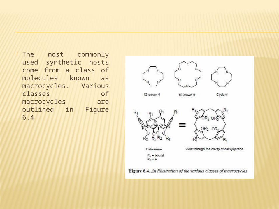
The most commonly used synthetic hosts come from a class of molecules known as macrocycles. Various classes of macrocycles are outlined in Figure 6.4
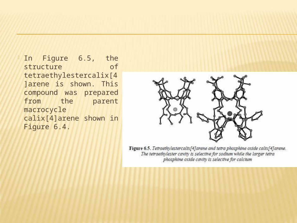
In Figure 6.5, the structure of tetraethylestercalix[4]arene is shown. This compound was prepared from the parent macrocycle calix[4]arene shown in Figure 6.4.
IMMOBILIZATION OF HOST MOLECULES Once hosts that are selective for
specific analytes have been developed, it is then necessary to immobilize these compounds into the sensor device. The most widely used method is the incorporation of the host molecule into flexible polymer membranes, which are then fixed into the sensor.
TRANSDUCTION OF SIGNALWith most sensors, transduction is accomplished either electrochemically or by optical detection. An electrochemical mode of detection usually requires that the membranes, which contain the host molecule, be placed onto an electrode surface and, upon binding of the guest, an electrochemical response is observed. This approach works very well when the target analytes are charged species such as the metal cations described above. Unfortunately neutral molecules are not as readily detected by this method. To overcome this problem, optical methods of detection have been successfully used. These optical methods are often more sensitive than electrochemical transduction techniques.
ELECTROCHEMICAL SENSORS electrochemical sensors are based on one of
three categories of transduction mechanism: amperometric and voltammetric, potentiometric or conductimetric. Amperometry senses current generated (at a fixed voltage) when an analyte is selectively oxidized or reduced resulting in the exchange of electrons. Two-electrode cells are common. In voltammetry, current is again measured, but as a function of the applied potential.
AMPEROMETRIC AND VOLTAMMETRIC SENSORS
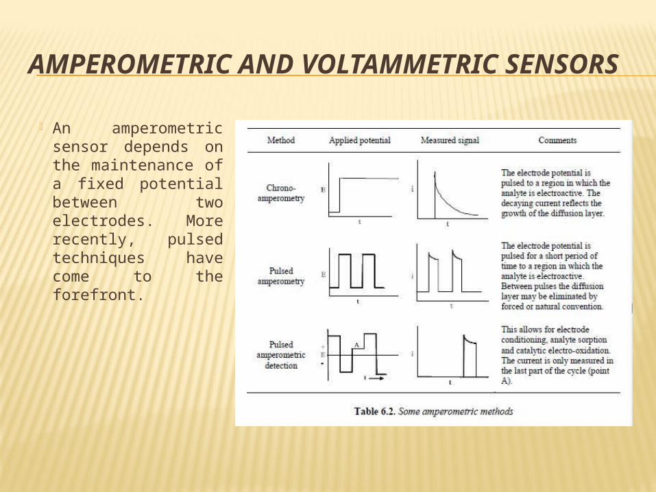
An amperometric sensor depends on the maintenance of a fixed potential between two electrodes. More recently, pulsed techniques have come to the forefront.
CYCLIC VOLTAMMETRY
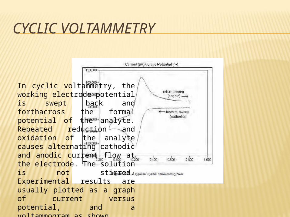
In cyclic voltammetry, the working electrode potential is swept back and forthacross the formal potential of the analyte. Repeated reduction and oxidation of the analyte causes alternating cathodic and anodic current flow at the electrode. The solution is not stirred. Experimental results are usually plotted as a graph of current versus potential, and a voltammogram as shown
HYDRODYNAMIC AMPEROMETRY
Methods involving forced convection (i.e. stirring) to aid the analyte to reach the electrode are called hydrodynamic methods. When the solution in stirred in a controlled mode, a non-turbulent flow of solution can be directed towards the working electrode.
POTENTIOMETRIC SENSORS Potentiometry is one of the oldest analytical
methods which is still widely used for electrochemical analysis. The most common potentiometric sensors are ISEs, which yield information about the concentration of a compound in terms of the potential difference between two electrodes.
The method is popular because of its simplicity, selectivity and relatively low cost.
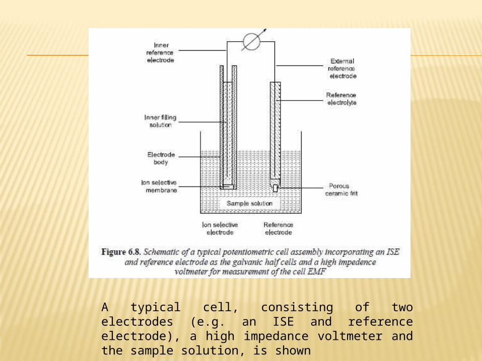
A typical cell, consisting of two electrodes (e.g. an ISE and reference electrode), a high impedance voltmeter and the sample solution, is shown
ION-SELECTIVE ELECTRODES
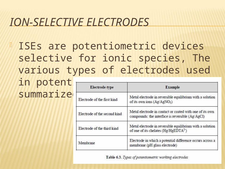
ISEs are potentiometric devices selective for ionic species, The various types of electrodes used in potentiometric cells are summarized in Table 6.3.
COATED-WIRE ELECTRODES AND POLYMER-MEMBRANE ELECTRODES
CWEs are constructed with the deposition of a crystalline membrane on a metallic wire electrode either electrolytically deposited or in conjunction with a polymer material such as PVC. Electrodes which are coated with a layer of salt by a chemical reaction are known as electrodes of the second kind. These provide a source of the ionic species and ensure that the solution near the electrode is saturated with it.
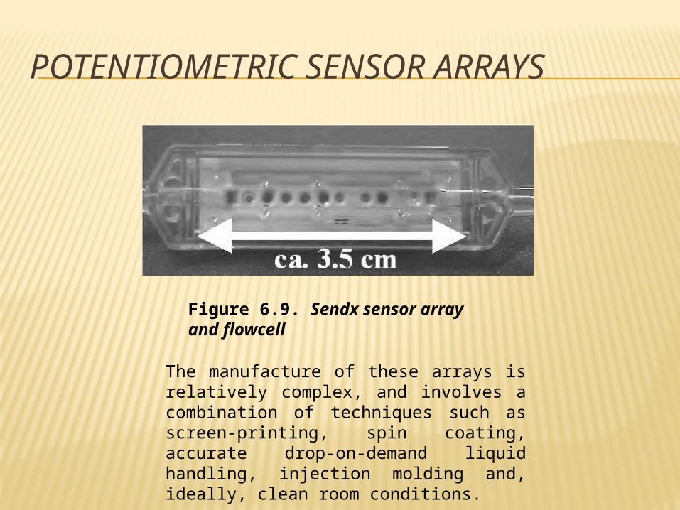
POTENTIOMETRIC SENSOR ARRAYS
Figure 6.9. Sendx sensor array and flowcell
The manufacture of these arrays is relatively complex, and involves a combination of techniques such as screen-printing, spin coating, accurate drop-on-demand liquid handling, injection molding and, ideally, clean room conditions.
RESISTANCE, CONDUCTANCE AND IMPEDANCE SENSORS
Some electrochemical sensors are based on measuring the change of electrical conducting properties of the sensing layer as a result of interactions between the analyte and (a certain component of) the sensing layer.
The sensor acts as an additional resistor and the voltage change due to the change of the resistance of the sensor is recorded. The output may be in the form of a voltage drop (V) or a conductivity change (ohm).
The advantages of these semiconductor-based sensors are:– easy fabrication (by sputtering);– simple operation; and– low production cost.
OPTICAL SENSORSOptical techniques for chemical and biological analysis are well established. In many cases, sensors based on these techniques use optical fiber technology, although planar waveguide configurations are increasingly favored. Optical sensor devices can be used for the detection and determination of physical or chemical parameters through the measurement of changes in some optical property.
EVANESCENT WAVE SENSORS
The motivation for embracing this evanescent wave (EW) approach is due to a number of advantages it offers:
– It is easy to miniaturize and no coupling optics are required– It is possible to discriminate between surface and bulk
effects by controlling the launch optics.– Sensitivity can be higher when compared to bulk optic
approaches.– Highly absorbing or highly scattering media are suited to
this technique because the effective path length is so small and scattering does not interfere to the same extent.
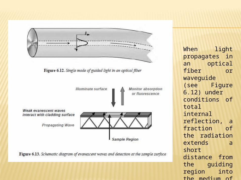
When light propagates in an optical fiber or waveguide (see Figure 6.12) underconditions of total internal reflection, a fraction of the radiation extends a short distance from the guiding region into the medium of lower refractive index that surrounds it (see Figure 6.13)
METHODS OF DETECTION
Most optical sensors are based on a spectroscopic technique such as measurement of absorbance, reflectance or fluorescence, where the signal obtained is related to the concentration of the analyte. The two most popular methods are absorption and fluorescence.
REAGENT-MEDIATED SENSORS Reagent-mediated sensors (optrodes) employ an intermediate reagent
which responds optically to the presence of the analyte of interest. These reactions are often adapted from well-established color chemistries and can be extremely sensitive. The optimal reagent should be very sensitive to and selective for the analyte, exhibit reversibility on removal of the analyte and respond quickly. If the sensor is not reversible, it is generally referred to as a probe as opposed to a sensor.
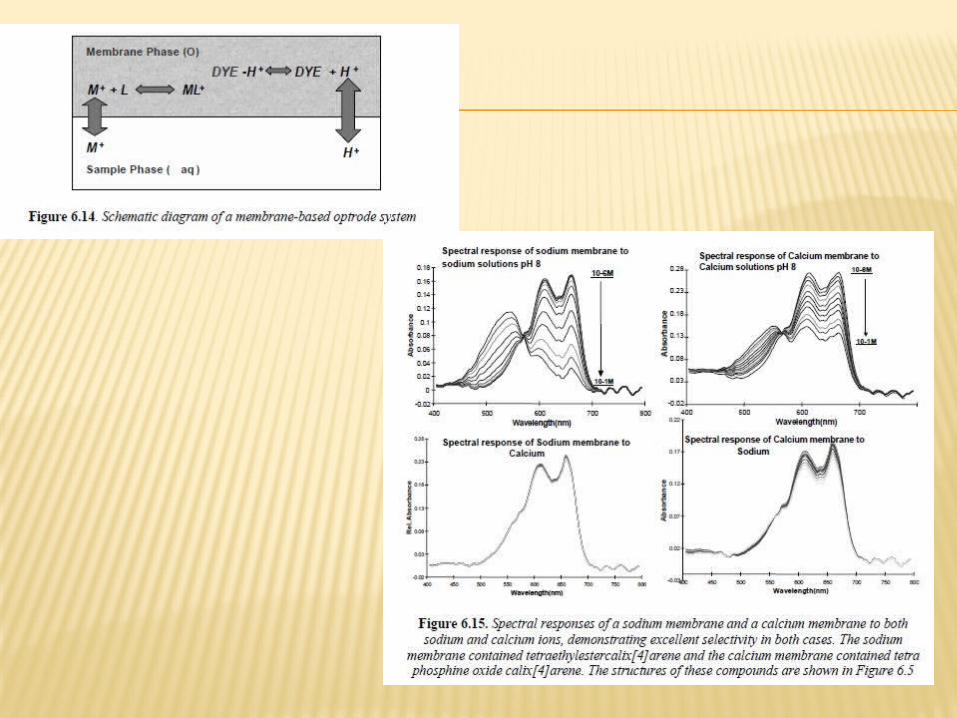
The example given below in Figure 6.14 shows a membrane-based optrode system using a ligand (L) to extract the analyte ion (M+) into the membrane to form a ligand-analyte complex (ML+). In the presence of this ML+ complex, and in order to maintain charge balance, the dye loses a proton and changes color from red to blue
The two membranes used in Figure 6.15 were formulated using calix[4]arene compounds known to have cavities of the correct size for sodium and calcium, i.e. tetraethylestercalix[4]arene and tetraphosphineoxidecalix[4]arene respectively
ACOUSTIC (MASS) SENSORS When a voltage is applied across an
anisotropic crystal, such as quartz, it will induce an acoustic wave, which will cause the crystal lattice to move. This acoustic wave will match that of the fundamental frequency, or harmonics, of the crystal and is dependent on its mass.
These sensors can thus be called acoustic or mass sensors.
QUARTZ CRYSTAL MICROBALANCE SENSORS
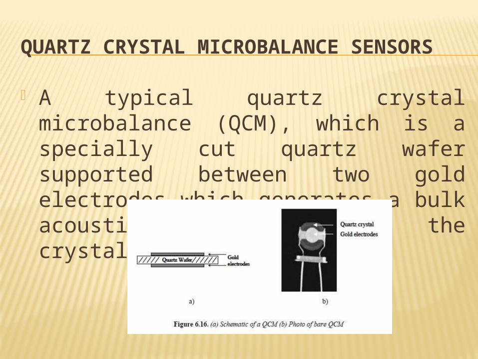
A typical quartz crystal microbalance (QCM), which is a specially cut quartz wafer supported between two gold electrodes which generates a bulk acoustic wave through the crystal.
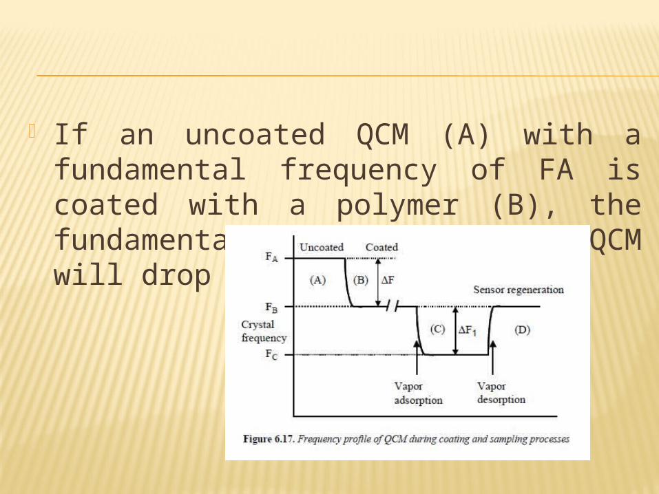
If an uncoated QCM (A) with a fundamental frequency of FA is coated with a polymer (B), the fundamental frequency of the QCM will drop to FB
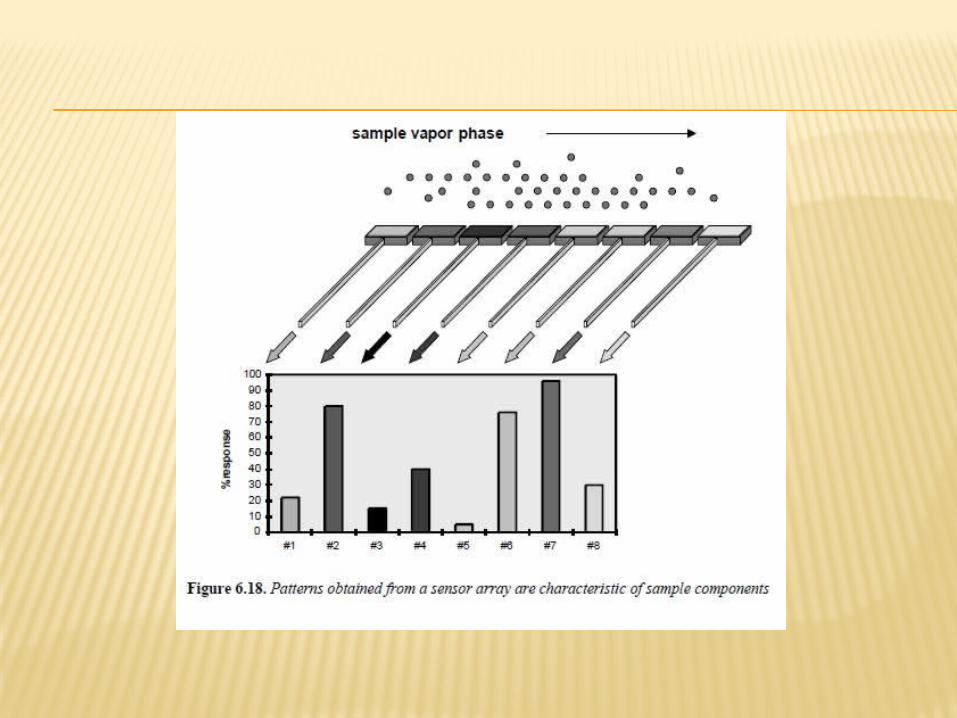
SENSOR ARRAYS Using an array of sensors with different
chemical properties will allow a specific pattern or fingerprint response for each solvent to be generated.
This fingerprint could be assigned to a particular analyte and a library of such responses could be built up.
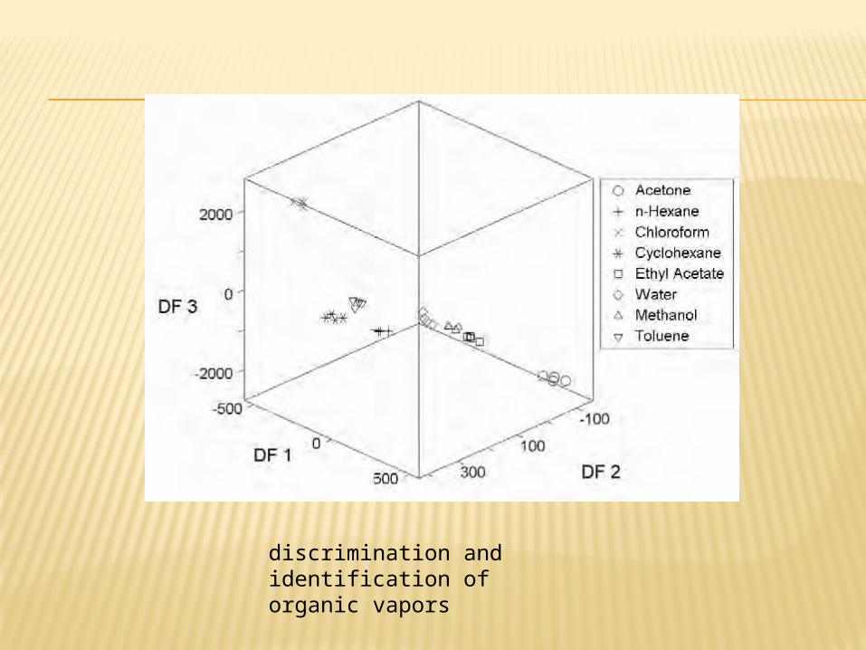
discrimination and identification of organic vapors
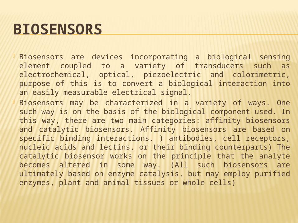
BIOSENSORS Biosensors are devices incorporating a biological sensing element
coupled to a variety of transducers such as electrochemical, optical, piezoelectric and colorimetric, purpose of this is to convert a biological interaction into an easily measurable electrical signal.
Biosensors may be characterized in a variety of ways. One such way is on the basis of the biological component used. In this way, there are two main categories: affinity biosensors and catalytic biosensors. Affinity biosensors are based on specific binding interactions. ) antibodies, cell receptors, nucleic acids and lectins, or their binding counterparts) The catalytic biosensor works on the principle that the analyte becomes altered in some way. (All such biosensors are ultimately based on enzyme catalysis, but may employ purified enzymes, plant and animal tissues or whole cells)
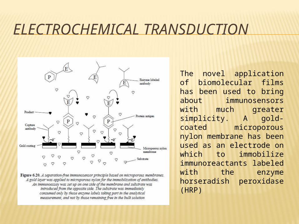
ELECTROCHEMICAL TRANSDUCTION
The novel application of biomolecular films has been used to bring about immunosensors with much greater simplicity. A gold-coated microporous nylon membrane has been used as an electrode on which to immobilize immunoreactants labeled with the enzyme horseradish peroxidase (HRP)

AFFINITY BIOSENSORS
PIEZOELECTRIC TRANSDUCTION
The piezoelectric (PE) effect is based on the principle that certain crystalline materials – most notably quartz – oscillate at a certain frequency when stimulated with a voltage. This principle serves as the basis for two distinct types of biosensor. These are the resonant QCM and the SAW device.
The type of device depends mostly on the configuration of the quartz crystal.
SPR BIOSENSORS
Several biosensors have been developed based on the phenomenon of SPR which allows the detection of biomolecular interactions in “real time”. The principle behind SPR is described in the context of BIAcore for convenience,
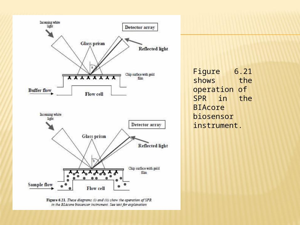
Figure 6.21 shows the operation ofSPR in the BIAcore biosensor instrument.
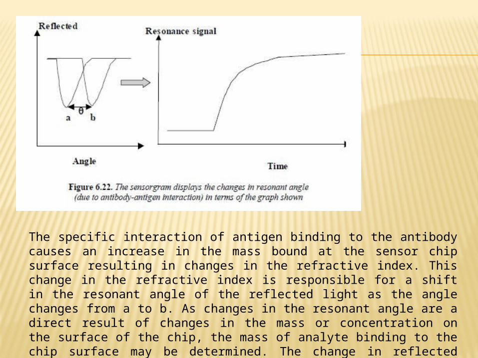
The specific interaction of antigen binding to the antibody causes an increase in the mass bound at the sensor chip surface resulting in changes in the refractive index. This change in the refractive index is responsible for a shift in the resonant angle of the reflected light as the angle changes from a to b. As changes in the resonant angle are a direct result of changes in the mass or concentration on the surface of the chip, the mass of analyte binding to the chip surface may be determined. The change in reflected light is interpolated as a sensorgram
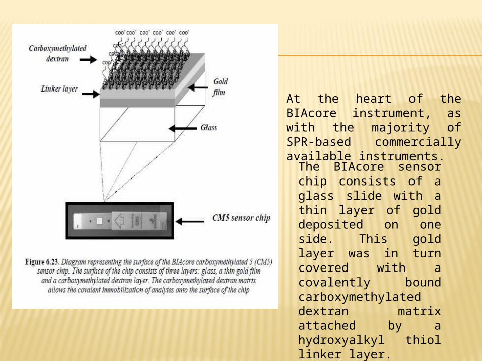
At the heart of the BIAcore instrument, as with the majority of SPR-based commercially available instruments.
The BIAcore sensor chip consists of a glass slide with a thin layer of gold deposited on one side. This gold layer was in turn covered with a covalently bound carboxymethylated dextran matrix attached by a hydroxyalkyl thiol linker layer.
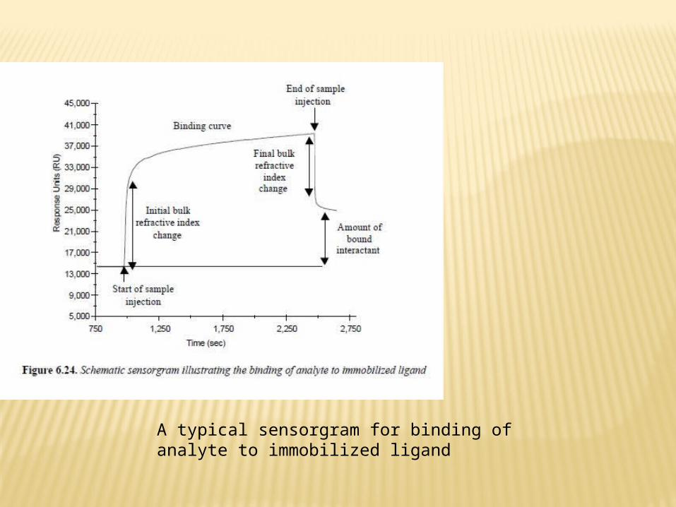
A typical sensorgram for binding of analyte to immobilized ligand

PROTEOMICS
In its infancy, proteomics was the word used to describe technology that allowed large-scale protein separation and mass identification. However, recently proteomics has divided into three areas, protein profiling, interaction analysis and structural genomics
IASYS BIOSENSOR The IAsys (IA means immunoaffinity) series of
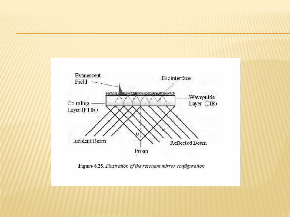
optical biosensors are analytical instruments that utilize advanced resonant mirror optical biosensor technology and apply it to the recognition of biomolecules.
A dielectric layer of high refractive index is used instead of the gold sensing layer in BIAcore. The sensor consists of a glass prism coated with a thin layer of silica and high refractive index resonant layer (e.g. titanium), which is in contact with the sample solution.
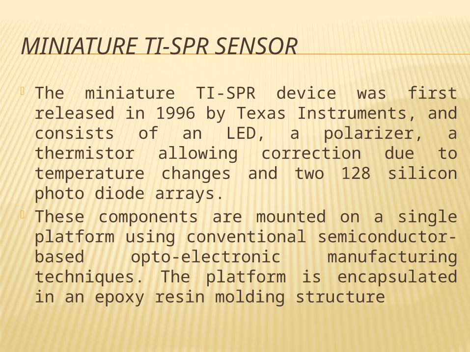
MINIATURE TI-SPR SENSOR The miniature TI-SPR device was first released
in 1996 by Texas Instruments, and consists of an LED, a polarizer, a thermistor allowing correction due to temperature changes and two 128 silicon photo diode arrays.
These components are mounted on a single platform using conventional semiconductor-based opto-electronic manufacturing techniques. The platform is encapsulated in an epoxy resin molding structure
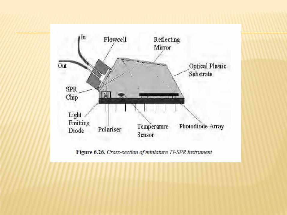
CATALYTIC BIOSENSORS Enzymes are proteins that act as biological catalysts. They
play very many essential roles in the functioning of all biological metabolism. As illustrated below, enzymes (E) transform a substrate (S) into a product (P) by forming a stable, shortlived enzyme-substrate intermediate (ES):E +S → ES → E+P
Enzymes are involved in the transformation of many clinically or industrially relevant substances such as glucose, lactate, creatinine etc. Using enzymes that transform such species is the basis of the largest group of biosensors in use. Enzymes can also be stably attached to transducer surfaces and can be stored for reasonable periods.

ELECTROCHEMICAL TRANSDUCTION The principle was first illustrated by Clark and Lyons in 1962. Their
approach, which utilized an electrochemical transducer in combination with a bioselective layer containing an enzyme, is still the most widely studied and used configuration of biosensor.
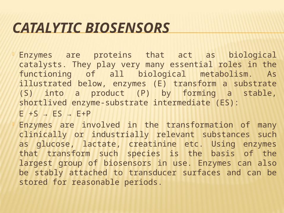
Their system was based on the oxygen electrode. This consisted of a platinum cathode, a silver anode and an oxygen-permeable membrane. To measure oxygen at the electrode passing through the membrane, the oxygen was reduced at a potential of –0.7 V to form hydrogen peroxide: O2 + 2 e- + 2 H+ → H2O2
The current produced is proportional to the amount of oxygen reduced. Clark and Lyons then used an enzyme that required oxygen to bring about the oxidation of a biochemical molecule. Such enzymes are referred to as oxidases. They chose glucose oxidase, which oxidizes β-D-glucose to gluconic acid and hydrogen peroxide: Glucose oxidaseβ-D-Glucose + O2 + H2O → Gluconic acid + H2O2
When the enzyme layer is held in intimate association with the platinum electrode surface.
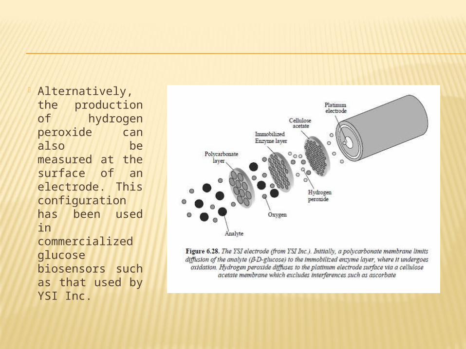
Alternatively, the production of hydrogen peroxide can also be measured at the surface of an electrode. This configuration has been used in commercialized glucose biosensors such as that used by YSI Inc.
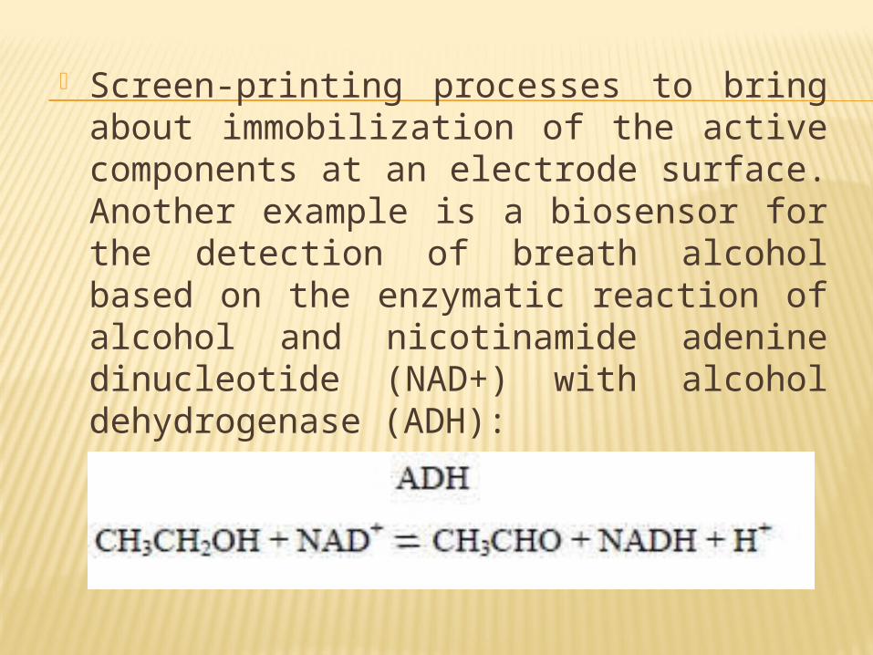
Screen-printing processes to bring about immobilization of the active components at an electrode surface. Another example is a biosensor for the detection of breath alcohol based on the enzymatic reaction of alcohol and nicotinamide adenine dinucleotide (NAD+) with alcohol dehydrogenase (ADH):
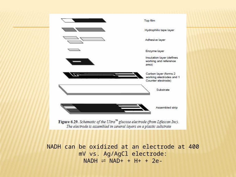
NADH can be oxidized at an electrode at 400 mV vs. Ag/AgCl electrode:
NADH ⇌ NAD+ + H+ + 2e-
CALORIMETRIC TRANSDUCTION In these devices, the enthalpy changes that accompany
all chemical and biochemical reactions can be measured and be related back to the quantity of analyte being measured. Most biochemical reactions are exothermic. Enzyme reactions typically have an enthalpy of around 80 kJ.mol-1.
Enzyme thermistors have the significant drawback of being very non-specific. To compensate, reference cells must be used. In addition, they must be carefully isolated from external temperature variations. The choice of support in this application is controlled pore glass, to which the enzyme is attached via glutaraldehyde cross-linking

FUTURE TRENDSTo reduce the cost of environmental analysis and in vitro diagnostics (IVDs), environmental and medical device designers are searching for new technologies that will enable them to develop high-quality instruments at a fraction of the cost of current laboratory systems, miniaturization of flow-based analysis is today an actively pursued topic in analytical chemical analysis.
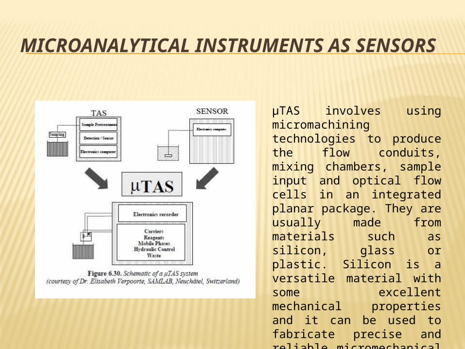
MICROANALYTICAL INSTRUMENTS AS SENSORS
μTAS involves using micromachining technologies to produce the flow conduits, mixing chambers, sample input and optical flow cells in an integrated planar package. They are usually made from materials such as silicon, glass or plastic. Silicon is a versatile material with some excellent mechanical properties and it can be used to fabricate precise and reliable micromechanical microstructures that can be integrated with the microfluidic system
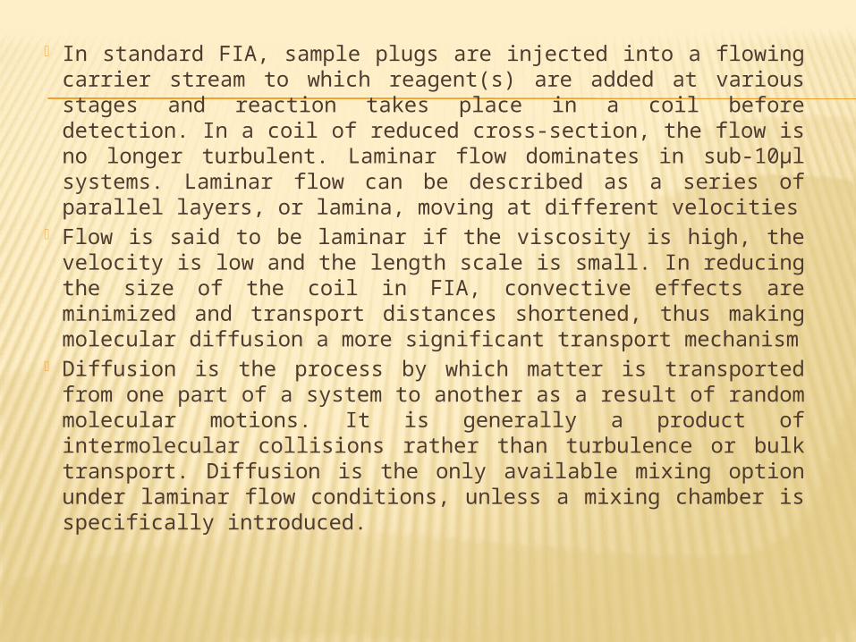
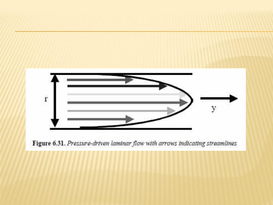
In standard FIA, sample plugs are injected into a flowing carrier stream to which reagent(s) are added at various stages and reaction takes place in a coil before detection. In a coil of reduced cross-section, the flow is no longer turbulent. Laminar flow dominates in sub-10μl systems. Laminar flow can be described as a series of parallel layers, or lamina, moving at different velocities
Flow is said to be laminar if the viscosity is high, the velocity is low and the length scale is small. In reducing the size of the coil in FIA, convective effects are minimized and transport distances shortened, thus making molecular diffusion a more significant transport mechanism
Diffusion is the process by which matter is transported from one part of a system to another as a result of random molecular motions. It is generally a product of intermolecular collisions rather than turbulence or bulk transport. Diffusion is the only available mixing option under laminar flow conditions, unless a mixing chamber is specifically introduced.
DESIGN CONSIDERATIONS The key goal of a microsystem is to manipulate and
control sample and reagent delivery through miniaturization and integration of the flow set-up.
Three factors to contemplate when considering the design of a microfluidic chip are:
– the chemistry involved in the analysis (number of reagents, mixing channels, kinetics, materials compatibility, etc.);
– the mode of detection (electrochemical, direct optical, reagent-based optical, etc.);
– the physical and chemical characteristics of the material used to make the chip.
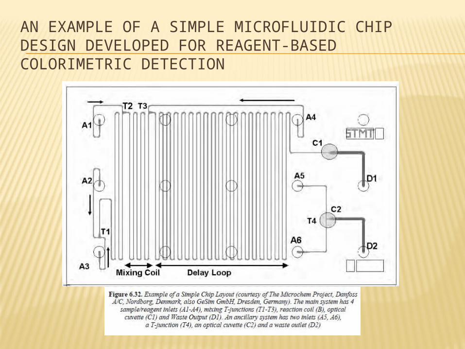
AN EXAMPLE OF A SIMPLE MICROFLUIDIC CHIP DESIGN DEVELOPED FOR REAGENT-BASEDCOLORIMETRIC DETECTION
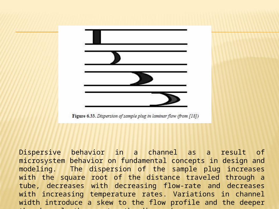
Dispersive behavior in a channel as a result of microsystem behavior on fundamental concepts in design and modeling. The dispersion of the sample plug increases with the square root of the distance traveled through a tube, decreases with decreasing flow-rate and decreases with increasing temperature rates. Variations in channel width introduce a skew to the flow profile and the deeper the channel, the greater the dispersion
ON-CHIP CHROMATOGRAPHIC AND ELECTROPHORETIC SEPARATIONS
The miniaturization of analytical separation techniques to a scale at which separations can be performed “on-chip” as part of μTAS devices has been a growing interest.
Of course, as with any new technologies there exist the inevitable technical hurdles to be overcome.
With on-chip analytical separation devices these currently include problems with sample injection, limited range of suitable microscale pumps (for liquid chromatographic systems), inflexible detection options and rather poor concentration-based detection limits.
the emergence of “on-chip” liquid chromatographic separations has been slow. This is due to several reasons, not least the lack of integratable highpressure pumps and valves to provide a non-pulsating mobile phase flow at pressures of up to 400 bar.
However, despite these technical problems, the principles and various modes of on-chip liquid chromatography have been extensively explored.
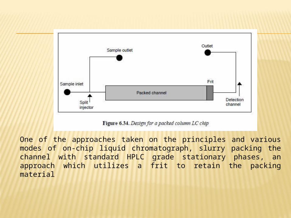
One of the approaches taken on the principles and various modes of on-chip liquid chromatograph, slurry packing the channel with standard HPLC grade stationary phases, an approach which utilizes a frit to retain the packing material
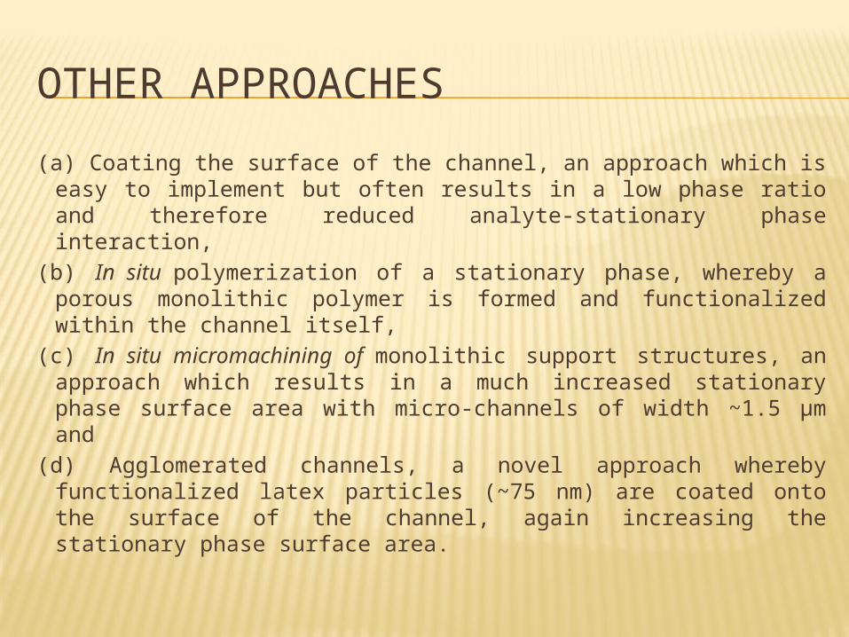
OTHER APPROACHES(a) Coating the surface of the channel, an approach which is
easy to implement but often results in a low phase ratio and therefore reduced analyte-stationary phase interaction,
(b) In situ polymerization of a stationary phase, whereby a porous monolithic polymer is formed and functionalized within the channel itself,
(c) In situ micromachining of monolithic support structures, an approach which results in a much increased stationary phase surface area with micro-channels of width ~1.5 μm and
(d) Agglomerated channels, a novel approach whereby functionalized latex particles (~75 nm) are coated onto the surface of the channel, again increasing the stationary phase surface area.
Once the mechanics of the stationary phase support structure have been mastered, it is possible to carry out many modes of on-chip LC depending upon the nature of the stationary phase itself.
On-chip electrophoretic separation techniques have dominated liquid chromatographic methods, The absence of moving parts and a pump and the ease of fabricating micro-electrodes into the chip means that electrophoretically-driven devices are assumed to be both mechanically and chemically, simpler than pressure driven LC devices.
TWO PHENOMENA THAT ARE CAUSING ON-CHIP CHANNEL ELECTROPHORESIS
The separation of charged species takes place under an applied electric field according to differences in size and charge. The rate of migration of these species under an applied electric field is given as their electrophoretic mobilities.
Within a channel possessing a charged surface (i.e. glass chips) and containing an electrolyte solution, an applied voltage will result in the bulk flow of the electrolyte solution in one direction. This is termed electro-osmotic flow (EOF) and is the liquid driving force behind electrophoretic separations.
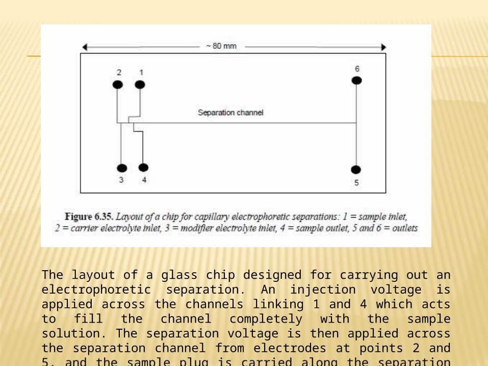
The layout of a glass chip designed for carrying out an electrophoretic separation. An injection voltage is applied across the channels linking 1 and 4 which acts to fill the channel completely with the sample solution. The separation voltage is then applied across the separation channel from electrodes at points 2 and 5, and the sample plug is carried along the separation channel, whereby the separation of the analytes takes place

AUTONOMOUS SENSING DEVICES
A key component in the development of these devices will be the ability to produce reliable analytical data over extended periods of time (ideally up to a year).
Requiring excellent reagent and instrument stability and very low power consumption and/or ability to search for power from the environment.
The merging of miniaturized computer systems and wireless communications will increase a remarkable demand for small, autonomous analytical systems based on micro-dimensioned instruments (μTAS or lab-on-a-chip) and/or chemical sensors and biosensors, as these will become the primary information sources about the “real world” for these emerging network-communication technologies.
SUB-MICRON DIMENSIONED SENSORS
MICROAMPEROMETRIC SENSORS Microelectrodes (ultramicroelectrodes):
electrodes whose critical dimension is in the micrometer range, although electrodes with radii as small as 10 Å have been fabricated.
Microelectrodes’ desirable attributes including, small currents, steady state responses and short response times.
In the past, the range of conditions under which electrochemical measurements could be made was restricted to highly conducting media, such as aqueous electrolyte solutions.
The small electrolysis currents observed at microamperometric sensors often completely eliminate these ohmic effects, so that it’s possible to quantify the concentrations of electroactive analytes in previously inaccessible samples such as non-polar solvents, supercritical fluids, and even solids and caused diffusional mass transport extremely efficient. And makes it possible to observe steady state responses when the applied potential is slowly scanned in cyclic voltammetry.
MICROELECTRODES IN BIOLOGICAL SYSTEMS
The critical dimension of a microelectrode is typically in the 0.1 to 50 μm range.
Many fabrication methods give electrodes in which the sensing area is microscopic, but the complete electrode is macroscopic (it’s around millimeters) so it’s not useful for performing electrochemistry in small volumes or for obtaining information about redox activity with high spatial resolution.
Therefore it needs other encapsulation methods such as, insertion of carbon fibers into microscopic tappered glass pipettes that are sealed with epoxy resin or electropolymerization of passivating polymer film around carbon fiber electrode. Both of these methods can give electrodes with total diameters in the tens of micrometers range.
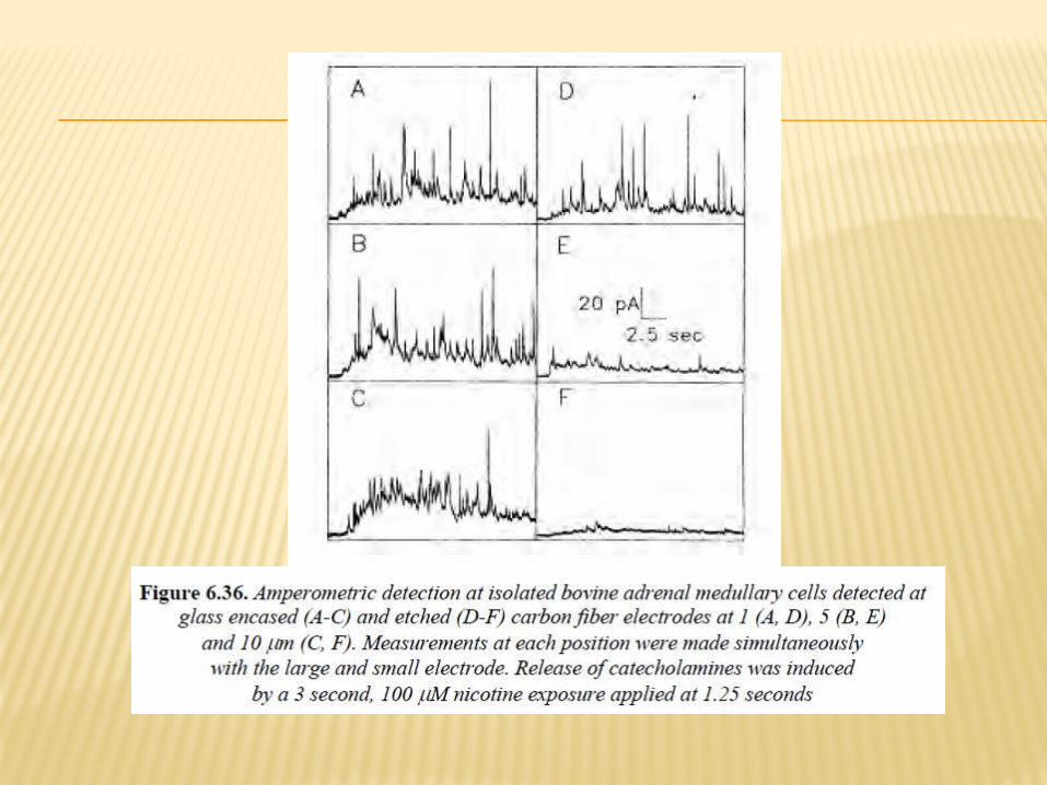
Research of microelectrodes is becoming more important in light of evidence that not only is the absolute concentration of a chemical messenger important in dictating a cellular response, but so too is the time profile (frequency) of the output.
Driving the electrode toward the cell causes the amplitude of the current spikes associated with catecholamines release to increase in amplitude and become narrower. (Figure 6.36)