Embed Size (px)
Citation preview
Chap
ter 6
Bridg
es an
d Grad
e Sep
aratio
nsChapter 6: Bridges, Over/Underpasses, RestAreas and Shuttle Sites
6-1.0 IntroductionThis chapter provides guidelines for planning and designing bikeways on bridges used by
vehicular traffic, bicycle and pedestrian overpasses and underpasses, and bicycle
accommodations at rest areas and scenic overlooks. The chapter concludes with a
discussion of bus or van shuttles across barriers to bicycle and pedestrian movement.
6-2.0 General ConsiderationsBridges provide essential links for bicyclists and pedestrians. Understanding the future
transportation demand, including bicycle and pedestrian modes, is an important step in life
cycle planning of bridges, which are typically reconstructed less frequently than connecting
roadways.
Bridges and interchanges on major highways are investments of public funds that are often
expected to result in new development and significant growth in travel demand. Designed
and constructed to last fifty years or more, bridges on or across highways should be planned,
designed and constructed with pedestrian and bicycle facilities appropriate for future
development patterns. For bridges in urban areas or other areas that are likely to see
increased development, this may require additional width and accommodations for bicycles
and pedestrian modes of travel on or under a bridge. In areas with low population density,
where development is unlikely, bicycles and pedestrians would be reasonably accommodated
by current design standards for bridge shoulders. Current bicycle and pedestrian demand
may not be a reasonable basis for planning and design of a bridge that will remain in service
for 50 years after construction, or up to 70 years after the time the bridge is planned.
The determination to provide a grade-separated crossing for bicycles and pedestrians should
be analyzed on a case-by-case basis. Analysis is based upon expected bicycle/pedestrian
traffic volume, latent demand for bicycle/pedestrian facilities, safety hazards, existing and
desired bicycle/pedestrian routing, motor vehicle speeds and volume, and other factors listed
in Chapter 4 of this manual. Table 5
where a grade-separated bikeway c
considered based on existing condit
Determining the appropriate type of
depends on practicality at an individ
constraints may dictate whether an
Mn/DOT Bikeway Facility Design Manual 169
-12 in Chapter 5 provides guidelines for conditions
rossing is warranted, but additional factors should be
ions and the community.
grade-separated crossing for bicycles and pedestrians
ual site. Topography, right-of-way limits, and other
underpass or overpass is more appropriate.
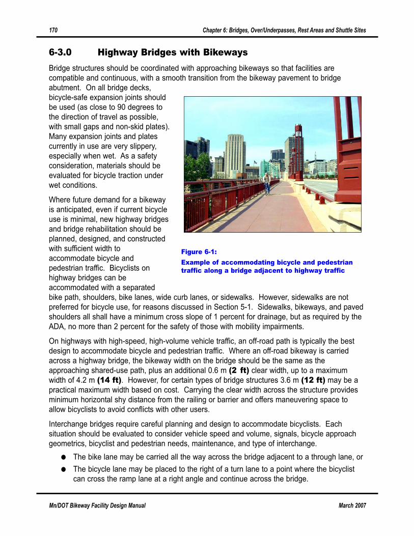
6-3.0 Highway Bridges with BikewaysBridge structures should be coordinated with approaching bikeways so that facilities are
compatible and continuous, with a smooth transition from the bikeway pavement to bridge
abutment. On all bridge decks,
bicycle-safe expansion joints should
be used (as close to 90 degrees to
the direction of travel as possible,
with small gaps and non-skid plates).
Many expansion joints and plates
currently in use are very slippery,
especially when wet. As a safety
consideration, materials should be
evaluated for bicycle traction under
wet conditions.
Where future demand for a bikeway
is anticipated, even if current bicycle
use is minimal, new highway bridges
and bridge rehabilitation should be
planned, designed, and constructed
with sufficient width to
accommodate bicycle and
pedestrian traffic. Bicyclists on
highway bridges can be
accommodated with a separated
bike path, shoulders, bike lanes, wide curb lanes, or sidewalks. However, sidewalks are not
preferred for bicycle use, for reasons discussed in Section 5-1. Sidewalks, bikeways, and paved
shoulders all shall have a minimum cross slope of 1 percent for drainage, but as required by the
ADA, no more than 2 percent for the safety of those with mobility impairments.
On highways with high-speed, high-volume vehicle traffic, an off-road path is typically the best
design to accommodate bicycle and pedestrian traffic. Where an off-road bikeway is carried
across a highway bridge, the bikeway width on the bridge should be the same as the
approaching shared-use path, plus an additional 0.6 m (2 ft) clear width, up to a maximum
width of 4.2 m (14 ft). However, for certain types of bridge structures 3.6 m (12 ft) may be a
practical maximum width based on cost. Carrying the clear width across the structure provides
minimum horizontal shy distance from the railing or barrier and offers maneuvering space to
allow bicyclists to avoid conflicts with other users.
Interchange bridges require careful planning and design to accommodate bicyclists. Each
situation should be evaluated to consider vehicle speed and volume, signals, bicycle approach
geometrics, bicyclist and pedestrian needs, maintenance, and type of interchange.
● The bike lane may be carried all the way across the bridge adjacent to a through lane, or
● The bicycle lane may be placed to the right of a turn lane to a point where the bicyclist
can cross the ramp lane at a right angle and continue across the bridge.
170 Chapter 6: Bridges, Over/Underpasses, Rest Areas and Shuttle Sites
Mn/DOT Bikeway Facility Design Manual March 2007
Figure 6-1:Example of accommodating bicycle and pedestriantraffic along a bridge adjacent to highway traffic
March 2007 Mn/DOT Bikeway Facility Design Manual
Chapter 6: Bridges, Over/Underpasses, Rest Areas and Shuttle Sites 171
● If a wide curb lane on the approach roadway is used to accommodate bicyclists, the extra
width should be carried across the bridge in a through lane.
● Where bicycles are legal on both roads, a bicycle lane, wide curb lane, or paved shoulder
should be included on the ramps, as well as across and under the bridge.
If there is not a designated bicycle or pedestrian facility on a highway bridge, paved shoulders
should be provided to accommodate one-way bicycle travel on each side of the bridge. When
shoulders are intended to facilitate bicycle traffic, a minimum of 1.5 m (5 ft) clear width should
be provided. Use Table 4-2 and the other factors listed in Chapter 4 to determine if wider
shoulders are warranted based upon vehicle traffic volume and speed.
Unless bicycles are prohibited by law from using the shoulder of a roadway, the shoulder surface
should be as smooth as the travel lanes on the bridge. Rumble strips are not used on bridge
shoulders.
6-3.1 Retrofitting Bikeways on Existing Highway BridgesOn many existing highway bridges, it is possible to use retrofits to accommodate bicyclists and
pedestrians. Certain bridge features, however, restrict bicycle access, create unfavorable
conditions for bicyclists, and make retrofitting difficult. These features include bridge width
narrower than the approach roadway (especially where combined with relatively steep grades),
open grated metal decks, low railings or parapets, and certain types of expansion joints, such as
finger-type joints, that can cause steering difficulties. These restrictions may be overcome by
adding width during reconstruction, creating a bike lane by filling open grating with lightweight
concrete, modifying railings, or adding a steel plate or elastomer filler to part of the joint. If a
stairway is the only feasible way to connect a shared-use path to a bikeway on an existing
bridge, a bicycle wheel ramp should be included on the stairway to facilitate walking a bicycle up
the stairs to the bridge.
Where a shared-use path is retrofitted onto a bridge, there are a large number of design
variables to consider. The best bikeway design must be determined for each case, using a
flexible approach to the design process. Several retrofit alternatives are suggested in this
section.
Carry the shared-use path across the bridge on one side This retrofit should be done where (1) the bridge facility will connect to a path at both ends, (2)
sufficient width exists on that side of the bridge or can be obtained by narrowing or re-striping
lanes, and (3) provisions are made to physically separate bicycle traffic from motor vehicle traffic.
If approach bikeways are two-way, the bridge’s bikeway facility should also be two-way.
An existing highway bridge over a barrier such as a roadway, railway, or waterway can be
reconfigured to add bicycle facilities for connecting shared-use paths running parallel to and on
opposite sides of the barrier. Where feasible, remove or reconfigure vehicle travel lanes to
include a 3 m (10 ft) vehicle shoulder and a 3-3.6 m (10-12 ft) shared-use path. The shared-
use path should be separated from vehicular traffic by a 1.2 m high (4 ft) barrier. This
configuration is illustrated in Figure 6-2.
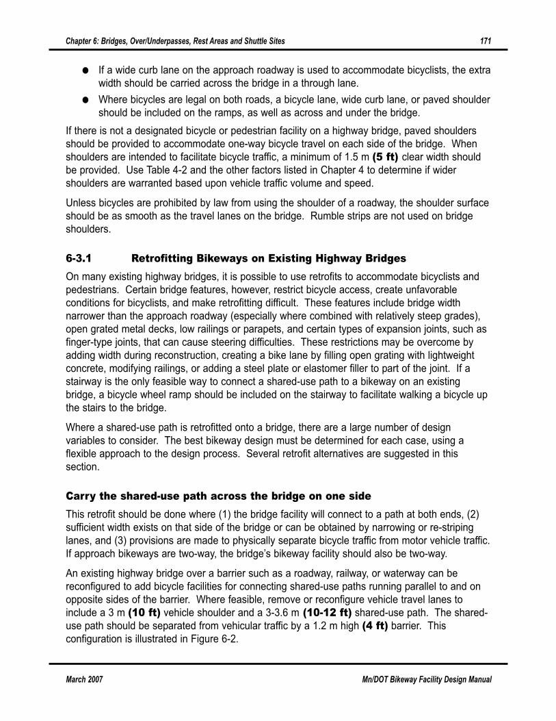
Provide wide curb lanes or bicycle lanes over the bridge This retrofit is advisable where (1) the shared-use path transitions into bicycle lanes at one end
of the bridge, (2) sufficient width exists or can be obtained by widening or re-striping, and (3)
there is a separate sidewalk for pedestrians. This option should only be exercised if the bike
lane or wide outside lane can be accessed without increasing the potential for wrong-way riding
or inappropriate crossing movements.
Consider using the existing bridge sidewalks for bicycle trafficThis retrofit may be appropriate when the sidewalk is wide enough to accommodate bicyclists
and pedestrians, particularly if the approach paths are one-way facilities. In general, however,
the designated use of sidewalks (as a signed, shared facility) for bicycle travel is unsatisfactory,
particularly if the sidewalk is raised and no railing exists between the sidewalk and traffic lanes.
Remember, too, that employing extremely wide sidewalks does not necessarily increase safety,
since wide sidewalks encourage higher bicycle speeds and increase potential conflicts with
pedestrians and fixed objects.
172 Chapter 6: Bridges, Over/Underpasses, Rest Areas and Shuttle Sites
Mn/DOT Bikeway Facility Design Manual March 2007
Figure 6-2:Shared-Use Path on Bridge with Barrier Separation
3.6 m(12 ft)
traffic lane
3.0 - 3.6 m(10 - 12 ft)
outsideshoulder
3.6 m(12 ft)
traffic lane
0.9 m(3 ft)inside
shoulder
3.6 m(12 ft)
traffic lane
15.0 - 15.5 m (49 - 51 ft)
3.6 m(12 ft)
traffic lane
0.9 m(3 ft)inside
shoulder
3.0 m(10 ft)outside
shoulder
3.6 m(12 ft)
traffic lane
.6 m(2 ft)
concretebarrier
3.0 - 3.6 m(10 - 12 ft)
shared-use pathPROPOSED
EXISTING
March 2007 Mn/DOT Bikeway Facility Design Manual
Chapter 6: Bridges, Over/Underpasses, Rest Areas and Shuttle Sites 173
Sidewalk bikeways should be considered only under certain limited circumstances where
unfriendly bicycle and pedestrian elements exist. For example, they may be appropriate on long,
narrow bridges where the rightmost travel lane is too narrow to accommodate both a cyclist and
motor vehicle.
Sidewalk bikeways must be at least 2.4 m (8 ft) wide, and preferably 3 m (10 ft) or greater.
Sidewalks should be modified to have adequate drainage and must be accessible to bicyclists
and pedestrians, including those with mobility impairments. Signage warning cyclists of
substandard bikeway conditions and a 1.4 m (4.5 ft) railing is required on the outside of the
sidewalk.
Where necessary, curb cuts and flush ramps shall be installed at path approaches so that
bicyclists are not subjected to the hazard of a vertical lip crossed at a flat angle. Curb cuts
should have a minimum width of 2.4 m (8 ft) to accommodate tricycles for adults and two-
wheeled bicycle trailers. A curb cut width of 1.8 m (6 ft), which meets ADA minimum
requirements, is not wide enough for bicycle traffic on a shared-use path.
6-3.2 Railings and Protective Screening on BridgesA list of standard railing applications for barriers on combined (vehicle traffic and
bicycle/pedestrian) bridges and bicycle/pedestrian bridges is provided in Table 13.2.1 of Chapter
13 (Railings) in the Mn/DOT LRFD Bridge Design Manual (October 2003). That manual
discusses three general classes of bridge railings or barriers:
● Traffic railings, designed to contain and redirect vehicles
● Bicycle/pedestrian railings, designed for pedestrian and bicyclist safety
● Combination railings, designed to contain bicycles as well as vehicles
Where a designated bikeway is constructed on a bridge, and motor vehicle speed is 45 mph or
greater, a traffic barrier is required between the bikeway and the vehicle lanes, with a
bicycle/pedestrian railing or combination railing on the outside edge of the bridge. The type of
traffic barrier required will depend on the speed of vehicular traffic. Additional considerations in
selecting barriers may include aesthetics, volume of vehicular traffic, and the expected amount of
bicycle and pedestrian traffic.
On bridges with motor vehicle speeds of 40 mph or less, where a bikeway is on a raised
sidewalk, or where a bicycle lane is striped on the roadway next to a raised sidewalk, a
combination railing may be used on the outside edge of the bridge without a traffic barrier
between the roadway and bikeway. The sidewalk curb height shall be 200 mm (8 in). If there is
no sidewalk, and the designated bikeway is at the same elevation as the roadway (bikeway on
the shoulder), a traffic barrier or combination railing should be used between the roadway and
the bikeway, with a bicycle/pedestrian railing or combination railing at the outside edge of the
bridge.
Bicycle/pedestrian railings must be a minimum height of 1.4 m (4.5 ft). For bridges over
roadways, the opening between elements of a bicycle/pedestrian railing or combination railing
shall not permit a 100 mm (4 in) sphere to pass through the lower 0.7 m (27 in) of the railing,
and a 150 mm (6 in) sphere shall not pass through any opening above 0.7 m (27 in).
Mn/DOT has developed a bicycle railing attachment to the Type F barrier for use when bridge
shoulders carry a bicycle route. (See Bridge Details Manual Part II, Figure 5-397.158.) This
railing may be applied to other traffic barriers where the same or greater offset distance to the
face of metal rail is provided and the post attachment has the same or greater strength.
If the bridge is over a roadway or railroad, protective screening or fencing to a height of 1.8 to
2.4 m (6 to 8 ft) is required to prevent objects from being thrown onto the roadway below.
Mn/DOT policy requires a protective screening system to be incorporated into the railing on new
bridges, or when railings are replaced on existing bridges. The standard height for protective
screening is 2.4 m (8 ft). The protective screening shall not allow passage of objects greater
than 150 mm (6 in).
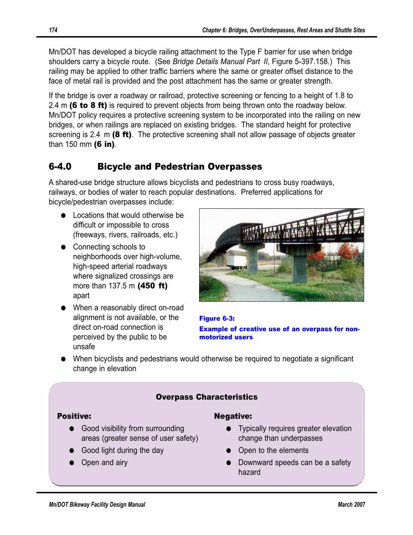
6-4.0 Bicycle and Pedestrian OverpassesA shared-use bridge structure allows bicyclists and pedestrians to cross busy roadways,
railways, or bodies of water to reach popular destinations. Preferred applications for
bicycle/pedestrian overpasses include:
● Locations that would otherwise be
difficult or impossible to cross
(freeways, rivers, railroads, etc.)
● Connecting schools to
neighborhoods over high-volume,
high-speed arterial roadways
where signalized crossings are
more than 137.5 m (450 ft)apart
● When a reasonably direct on-road
alignment is not available, or the
direct on-road connection is
perceived by the public to be
unsafe
● When bicyclists and pedestrians would otherwise be required to negotiate a significant
change in elevation
174 Chapter 6: Bridges, Over/Underpasses, Rest Areas and Shuttle Sites
Mn/DOT Bikeway Facility Design Manual March 2007
Figure 6-3:Example of creative use of an overpass for non-motorized users
Positive:● Good visibility from surrounding
areas (greater sense of user safety)
● Good light during the day
● Open and airy
Negative:● Typically requires greater elevation
change than underpasses
● Open to the elements
● Downward speeds can be a safety
hazard
Overpass Characteristics
March 2007 Mn/DOT Bikeway Facility Design Manual
Chapter 6: Bridges, Over/Underpasses, Rest Areas and Shuttle Sites 175
● When vehicular bridges do not provide bicycle route continuity and directness.
The design of a bicycle and pedestrian overpass shall consider requirements for grade, turning
radius, width, cross slope, and speed. In some cases, for the safety of all types of traffic, the
bicycle design speed may need to be reduced from the approaching bikeway. The profile across
a bridge should follow a smooth line with no sharp changes in grade over the piers.
To ensure the safety of users of all ability and skill level, bicycle and pedestrian overpasses
should be designed in accordance with the AASHTO Guide for the Development of BicycleFacilities (1999), the AASHTO Standard Specifications for Highway Bridges and the Mn/DOT
LRFD Bridge Design Manual. ADA standards for accessible design are also applicable, but, for
the most part, those have been incorporated into AASHTO standards, since accessible design
benefits bicyclists and able-bodied pedestrians as well as those with mobility impairments.
The recommended minimum width of an overpass for bicyclists and pedestrians is 3.6 m (12 ft),or the paved width of the approach path plus 0.6 m (2 ft), whichever is greater. The desirable
width of an overpass is the width of the approach path plus 1.2 m (4 ft). The bridge width is
measured from the face of handrail to face of handrail.
Carrying the clear areas across the structure provides necessary horizontal shy distance from
the railing and provides maneuvering space to avoid conflicts with pedestrians and oncoming
bicyclists. Access by emergency, patrol, and maintenance vehicles should be considered when
establishing vertical and horizontal clearances. The path’s shoulder width should taper as
necessary to match the overpass width (if applicable). Greater width may be appropriate in
heavily traveled urban corridors, and near university campuses or near facilities that have
pedestrian event-clearing peaks.
When physical constraints limit the width of a bicycle/pedestrian overpass, it may be necessary
to provide a substandard width. In very rare instances, a reduced width of 2.4 m (8 ft) may
used, but only where all of the following conditions occur:
● Bicycle traffic is expected to be low, even on peak days or during peak hours.
● Only occasional pedestrian use of the facility is expected.
● Horizontal and vertical alignment will provide safe and frequent passing opportunities.
● Normal maintenance vehicle loading conditions or widths will not exceed the bridge
design parameters.
● State Aid funds are not being used on the project.
The vertical clearance from the pavement to any overhead object on an overpass shall be a
minimum of 2.4 m (8 ft) for bicyclists, but 2.7 m (10 ft) vertical clearance may be appropriate
to accommodate occasional maintenance or security vehicles using the overpass. The vertical
clearance of the bottom of the overpass structure over a street or highway is typically at least 5.2
m (17 ft), but requirements must be verified on a case-by-case basis.
The access ramps for bicycle/pedestrian overpasses must meet ADA design standards, for which
the preferred maximum grade is 5 percent (20:1). However, grades up to 8.33 percent (12:1) are
permitted if a platform 1.5 m (5 ft) long is provided between each 0.75 m (2.5 ft) change in
elevation. A 1.8 m (6 ft) clear flat platform is to be provided at the bottom of each ramp.
Overpasses require railings for both bicyclists and pedestrians. The railing height for bicyclists
shall be 1.4 m (4.5 ft) from the overpass deck, with a pedestrian handrail at a height of 1.1 m
(3.5 ft). Where a bicycle/pedestrian overpass crosses a roadway or railway, 2.4 m (8 ft) high
protective screening shall be used to prevent objects from being thrown off the bridge. Refer to
Section 6-3.2 for guidance on bicycle/pedestrian railings and protective screening.
Structures designed for pedestrian live loads are satisfactory for bicycles. The Mn/DOT LRFDBridge Design Manual (Section 3.4.4, Pedestrian Live Load) specifies that bridges carrying only
bicycle/pedestrian traffic should be designed with a live load intensity of 0.085 ksf. However, if
maintenance and emergency vehicles may need access to the overpass, the structure must be
designed for the vehicle load.
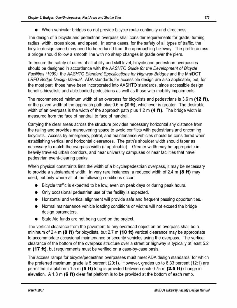
6-5.0 Bikeways Under Existing Bridge StructuresHighways, particularly freeways, can be significant barriers to bicycle and pedestrian movement.
Many bridges can be retrofitted to
provide a bicycle/pedestrian
crossing under the barrier by
creating a crossing where there are
no bicycle or pedestrian
accommodations, or by upgrading
the existing bicycle/pedestrian
crossing. Provide adequate lighting
under structures, in tunnels, and at
approaches.
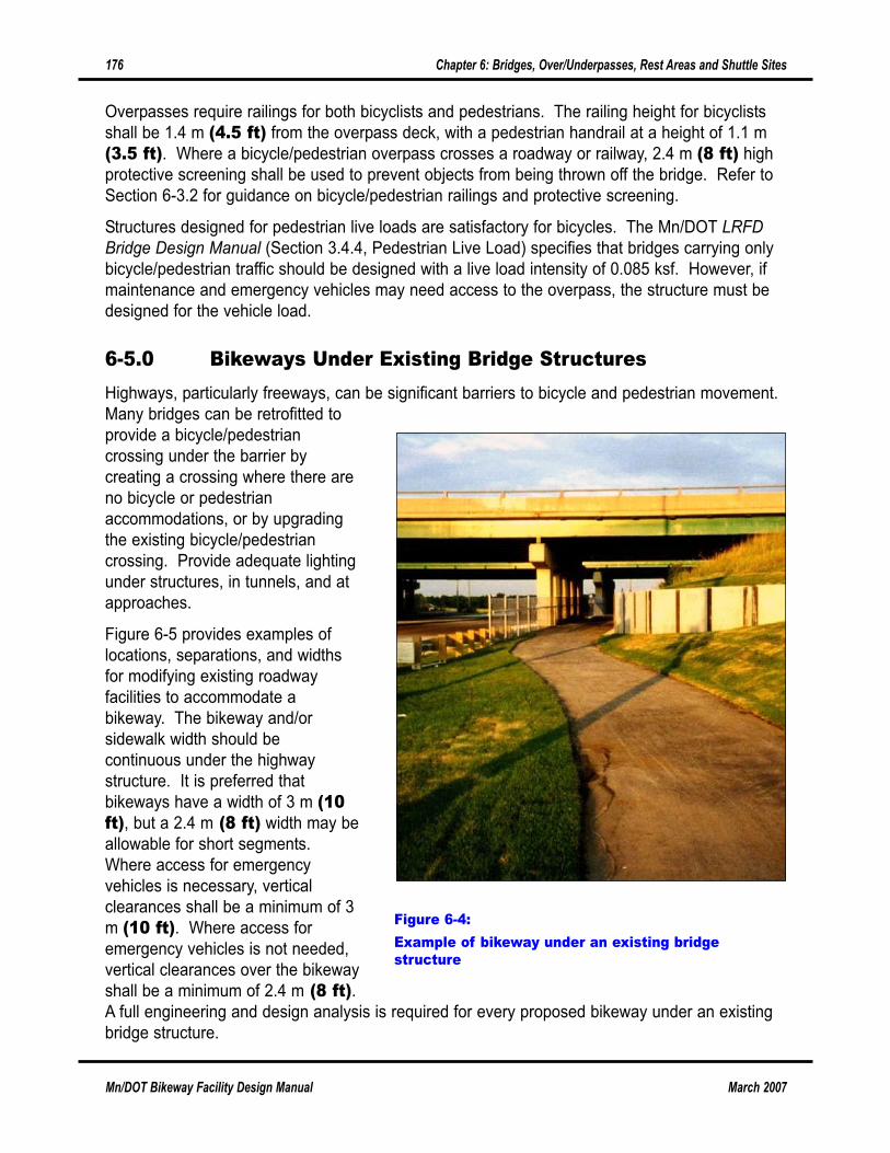
Figure 6-5 provides examples of
locations, separations, and widths
for modifying existing roadway
facilities to accommodate a
bikeway. The bikeway and/or
sidewalk width should be
continuous under the highway
structure. It is preferred that
bikeways have a width of 3 m (10ft), but a 2.4 m (8 ft) width may be
allowable for short segments.
Where access for emergency
vehicles is necessary, vertical
clearances shall be a minimum of 3
m (10 ft). Where access for
emergency vehicles is not needed,
vertical clearances over the bikeway
shall be a minimum of 2.4 m (8 ft).A full engineering and design analysis is required for every proposed bikeway under an existing
bridge structure.
176 Chapter 6: Bridges, Over/Underpasses, Rest Areas and Shuttle Sites
Mn/DOT Bikeway Facility Design Manual March 2007
Figure 6-4:Example of bikeway under an existing bridgestructure
March 2007 Mn/DOT Bikeway Facility Design Manual
Chapter 6: Bridges, Over/Underpasses, Rest Areas and Shuttle Sites 177
6-6.0 Bicycle and Pedestrian Underpasses and TunnelsA bikeway underpass should be considered if there is no safe and direct on-street crossing, if the
facility to be crossed is elevated, if an existing motor vehicle under-crossing is too narrow for a
bicycle facility, and when the underpass would not require bicyclists to negotiate significant
elevation changes. Underpass costs may be lower than those for overpasses.
Figure 6-5:Bikeway under an existing bridge structure
3 m (10 ft)Bikeway
Bridge
3 m (10 f
t)mi
n.
C L
Roadway
Rail or fenceas needed
Retaining wall or barrier wall
Earth fill
3 m (10 ft)Bikeway
Bridge
3 m (10 f
t)mi
n.
C L
Roadway
Rail or fenceas needed
Retaining wall or barrier wall Culvert
Earth fill
Positive:● Protected from weather
● Less ramping and change in
elevation than overpasses due to
clearance requirements
Negative:● Can be dark and intimidating
● Users may not be able to see
through to the other side
● Users may feel claustrophobic
● May be difficult to maintain
Underpass Characteristics
An underpass may have less grade change for a bicyclist to negotiate than an overpass because
a typical overpass requires a 5.2 m (17 ft) vertical clearance over the highway. A disadvantage
is that unless it is well located and
openly designed, it may be
intimidating and avoided by
bicyclists and pedestrians.
Providing adequate drainage may
also be a problem; providing a
surface that does not become
excessively slippery when wet is
important. Proper drainage design
is a key element to prevent wet silt
deposits that are a common hazard
for bicyclists using underpasses.
The inclusion of gutters at the edge
of the underpass and the base of a
retaining wall are good design
elements to ensure a clear riding
surface.
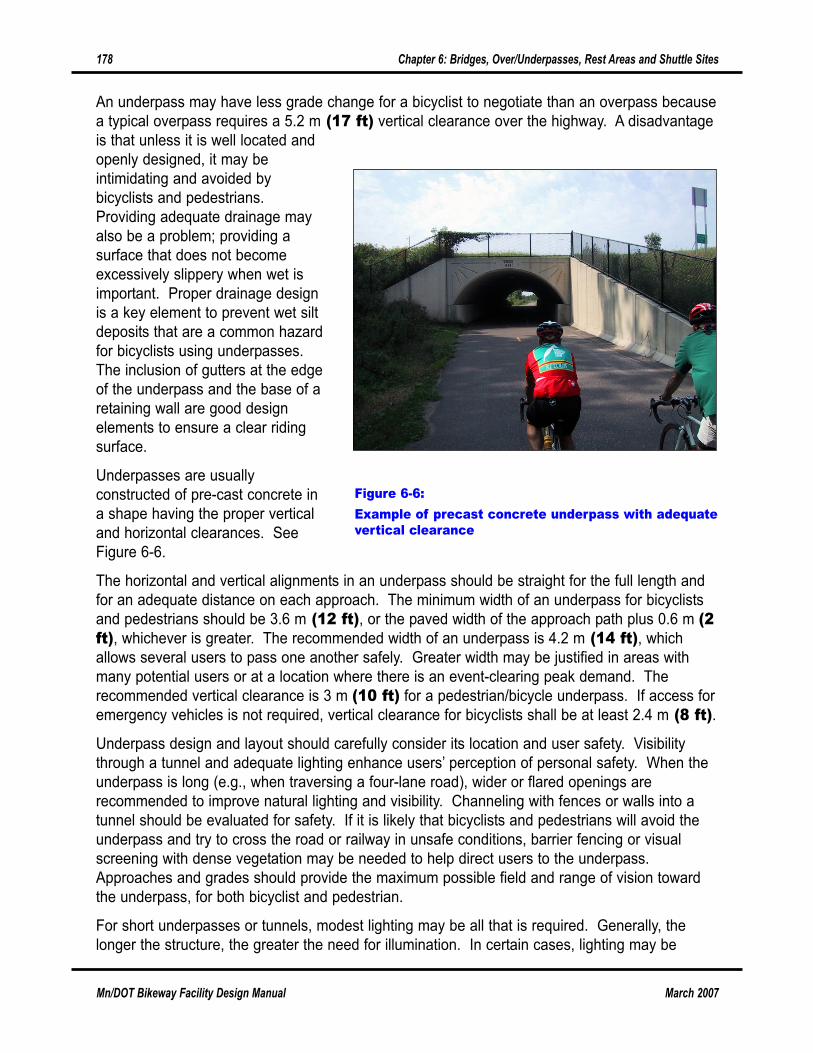
Underpasses are usually
constructed of pre-cast concrete in
a shape having the proper vertical
and horizontal clearances. See
Figure 6-6.
The horizontal and vertical alignments in an underpass should be straight for the full length and
for an adequate distance on each approach. The minimum width of an underpass for bicyclists
and pedestrians should be 3.6 m (12 ft), or the paved width of the approach path plus 0.6 m (2ft), whichever is greater. The recommended width of an underpass is 4.2 m (14 ft), which
allows several users to pass one another safely. Greater width may be justified in areas with
many potential users or at a location where there is an event-clearing peak demand. The
recommended vertical clearance is 3 m (10 ft) for a pedestrian/bicycle underpass. If access for
emergency vehicles is not required, vertical clearance for bicyclists shall be at least 2.4 m (8 ft).
Underpass design and layout should carefully consider its location and user safety. Visibility
through a tunnel and adequate lighting enhance users’ perception of personal safety. When the
underpass is long (e.g., when traversing a four-lane road), wider or flared openings are
recommended to improve natural lighting and visibility. Channeling with fences or walls into a
tunnel should be evaluated for safety. If it is likely that bicyclists and pedestrians will avoid the
underpass and try to cross the road or railway in unsafe conditions, barrier fencing or visual
screening with dense vegetation may be needed to help direct users to the underpass.
Approaches and grades should provide the maximum possible field and range of vision toward
the underpass, for both bicyclist and pedestrian.
For short underpasses or tunnels, modest lighting may be all that is required. Generally, the
longer the structure, the greater the need for illumination. In certain cases, lighting may be
178 Chapter 6: Bridges, Over/Underpasses, Rest Areas and Shuttle Sites
Mn/DOT Bikeway Facility Design Manual March 2007
Figure 6-6:Example of precast concrete underpass with adequatevertical clearance
March 2007 Mn/DOT Bikeway Facility Design Manual
Chapter 6: Bridges, Over/Underpasses, Rest Areas and Shuttle Sites 179
required on a daily, 24-hour basis. For tunnels longer than 15 m (50 ft), constant illumination is
recommended. All lighting should be recessed and vandal resistant. Providing skylights in the
middle of the structure (an opportunity occurring with an overhead urban section roadway with a
raised median) can reduce lighting needs during daylight hours. See Section 5-8 for more
information on lighting.
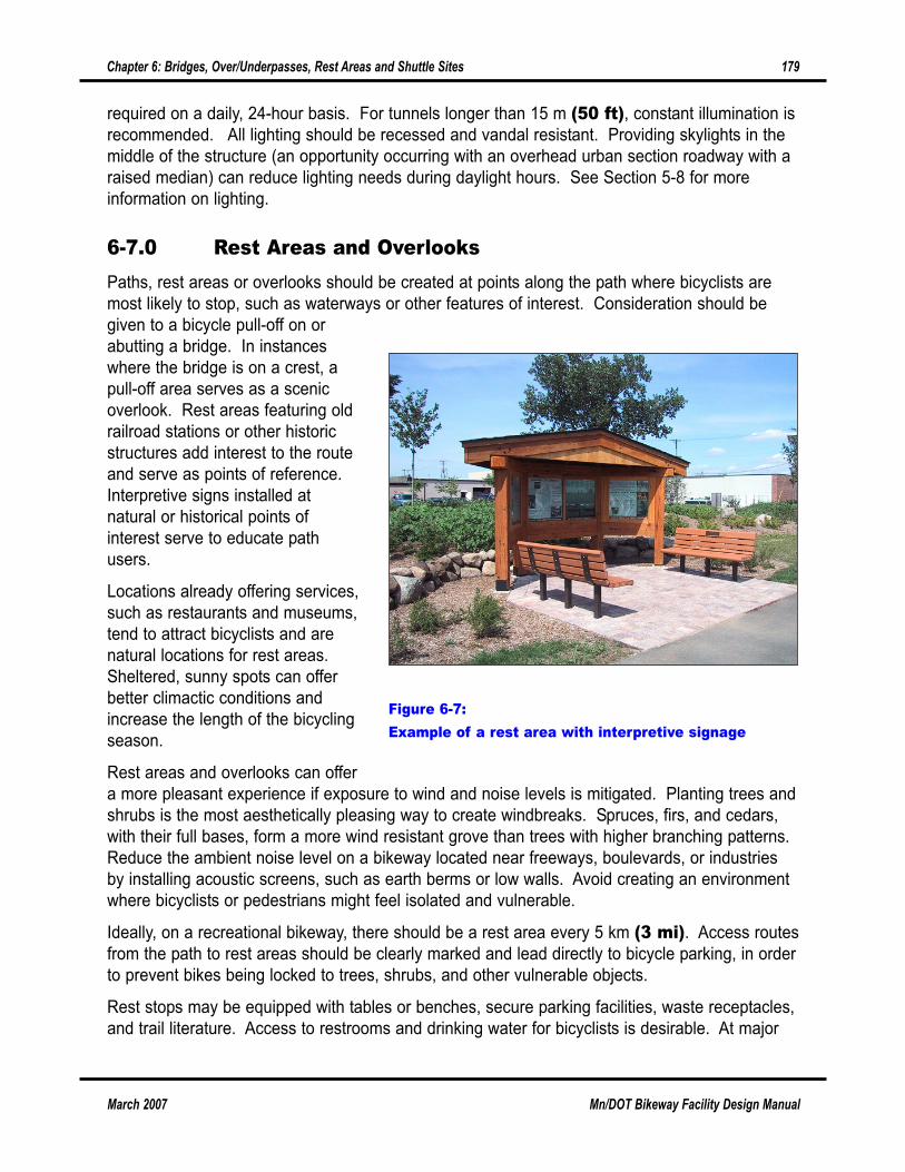
6-7.0 Rest Areas and OverlooksPaths, rest areas or overlooks should be created at points along the path where bicyclists are
most likely to stop, such as waterways or other features of interest. Consideration should be
given to a bicycle pull-off on or
abutting a bridge. In instances
where the bridge is on a crest, a
pull-off area serves as a scenic
overlook. Rest areas featuring old
railroad stations or other historic
structures add interest to the route
and serve as points of reference.
Interpretive signs installed at
natural or historical points of
interest serve to educate path
users.
Locations already offering services,
such as restaurants and museums,
tend to attract bicyclists and are
natural locations for rest areas.
Sheltered, sunny spots can offer
better climactic conditions and
increase the length of the bicycling
season.
Rest areas and overlooks can offer
a more pleasant experience if exposure to wind and noise levels is mitigated. Planting trees and
shrubs is the most aesthetically pleasing way to create windbreaks. Spruces, firs, and cedars,
with their full bases, form a more wind resistant grove than trees with higher branching patterns.
Reduce the ambient noise level on a bikeway located near freeways, boulevards, or industries
by installing acoustic screens, such as earth berms or low walls. Avoid creating an environment
where bicyclists or pedestrians might feel isolated and vulnerable.
Ideally, on a recreational bikeway, there should be a rest area every 5 km (3 mi). Access routes
from the path to rest areas should be clearly marked and lead directly to bicycle parking, in order
to prevent bikes being locked to trees, shrubs, and other vulnerable objects.
Rest stops may be equipped with tables or benches, secure parking facilities, waste receptacles,
and trail literature. Access to restrooms and drinking water for bicyclists is desirable. At major
Figure 6-7:Example of a rest area with interpretive signage
rest areas (or trailheads), minor repair services, telephones, and covered shelters may be made
available.
To facilitate entering and leaving a busy path, an access path extending 30 m (100 ft) on either
side of the rest area’s entrance may be created. This is especially recommended if the entrance
is located on a steep grade or is not visible at a distance of more than 40 m (130 ft). Aphysical demarcation such as a low-lying hedge or ditch may discourage crowds from gathering
on the path and prevent children from wandering onto it while playing.
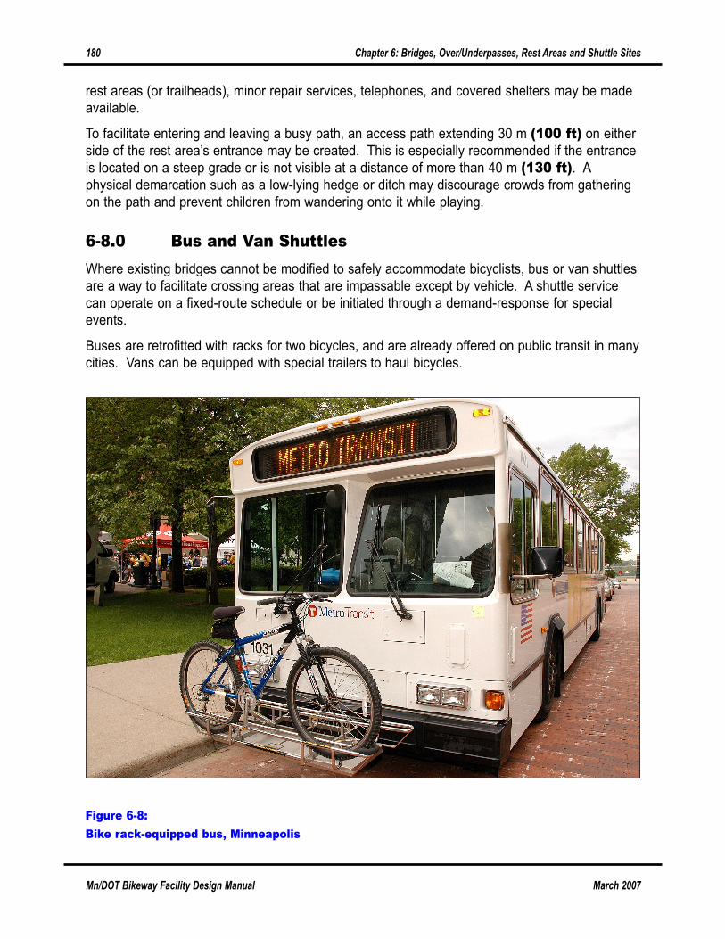
6-8.0 Bus and Van ShuttlesWhere existing bridges cannot be modified to safely accommodate bicyclists, bus or van shuttles
are a way to facilitate crossing areas that are impassable except by vehicle. A shuttle service
can operate on a fixed-route schedule or be initiated through a demand-response for special
events.
Buses are retrofitted with racks for two bicycles, and are already offered on public transit in many
cities. Vans can be equipped with special trailers to haul bicycles.
180 Chapter 6: Bridges, Over/Underpasses, Rest Areas and Shuttle Sites
Mn/DOT Bikeway Facility Design Manual March 2007
Figure 6-8:Bike rack-equipped bus, Minneapolis