Embed Size (px)
Citation preview

Chapter 5
Waveguide applications of localized
surface plasmons associated with
metallic nanocylinders
The surface plasmon polaritons [70, 71] provide high enhancement of electromag-
netic field near the vicinity of metallic nanostructures. When two nanoparticles
are brought together, interaction between individual surface plasmon modes gener-
ates additional resonances for the coupled system, provided the distance between
the two nanoparticles is small enough in comparison with their size [72, 73]. Thus
metallic nanoparticles can be implemented in application either by taking advantage
of their local filed enhancement effect or by propagating the surface plasmon po-
lariton modes over distances to build integrated optical waveguide circuits [74, 75].
The localized surface plasmon interactions between the individual nanoparticles
are attributed to the signal transfer through periodic nanostructures. The guiding
property of metallic nanoparticles to transport the electromagnetic energy below
79
80
diffraction limit has been studied intensively for a few decades [76, 77, 78, 79].
It has been observed that the local-field enhancement produced in the gap between
nanoparticles could be applied to a waveguide for improving the transmission length
of electromagnetic energy [80, 81, 82, 83, 84]. It is well understood that compared
to single chain systems, pair chains increase the local field and hence reduce propa-
gation losses [85, 86, 87, 88]. This chapter, discuss the plasmon guiding properties
of a waveguide made up of nanocylinders. Electromagnetic energy propagation
through dimer array is studied using FDTD method and it is discussed in section 1
of this chapter. Section 2 discuss the wave guiding properties of nanoshell cylinders
having triangular geometry.
5.1 Dimer Array
Surface plasmon propagation along nanocylinder arrays are an alternative to di-
electric waveguides in highly miniaturized integrated optical devices. The guiding
principle in such structures relies on coupled plasmon modes set up by the near field
dipole interactions. Finite difference time domain (FDTD) method is used for sim-
ulating dispersion of surface plasmon polaritons along silver nanocylinder arrays in
anisotropic dielectric surroundings.
5.1.1 Simulation Model
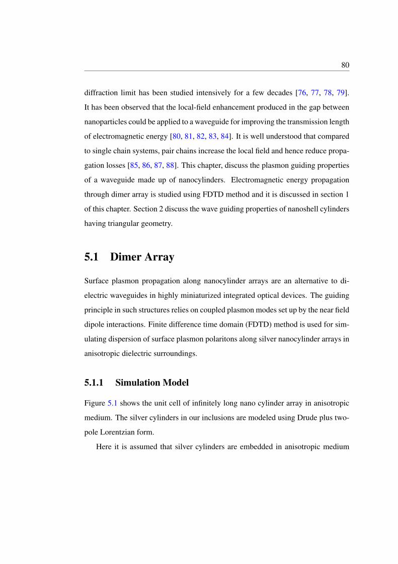
Figure 5.1 shows the unit cell of infinitely long nano cylinder array in anisotropic
medium. The silver cylinders in our inclusions are modeled using Drude plus two-
pole Lorentzian form.
Here it is assumed that silver cylinders are embedded in anisotropic medium
81
with large permittivity ratios which can be obtained either by using photonic crys-
tals or strained polymers [89].
Figure 5.1: The layout of the 2-D FDTD computation domain for calculating dis-persion diagram for 1-D dimer periodic structures.
The anisotropic medium with principal dielectric constants εx, εy and εz can be
expressed in tensor form as,
[εr] =
εx 0 0
0 εy 0
0 0 εz
(5.1)
FDTD method can be used to model periodic structures by applying Bloch’s
boundary conditions (PBCs). Bloch theory is satisfied by field at any point in peri-
odic structures, i.e,
E(d +a) = E(d)exp(ika) (5.2)
82
H(d +a) = H(d)exp(ika) (5.3)
where d is the distance vector of any location in computation domain, k is the wave
vector and a is the lattice vector along the direction of periodicity. Proper absorbing
boundary condition is used in FDTD method to truncate simulation domain without
artificial reflections. In this work absorbing boundary conditions are handled using
perfectly matched layers (PMLs), which is a fictitious absorbing material added
around edges of the cell. In two dimensional simulation domain transverse electric
modes with non zero Ex,Ey and Hz components are truncated using periodic bound-
ary conditions in x-direction and perfectly matched layers of thickness 100 nm in
y-direction. The radius of silver nano cylinders is 17 nm and lattice spacing is 54
nm. A line source parallel to the cylinder axes is considered to launch Gaussian
waves, which is proportional to exp(−iωt− (t− t0)2/2w2) where ω is the centre
frequency, w is width of the Gaussian pulse and t0 is the initial time.
5.1.2 Results and Discussion
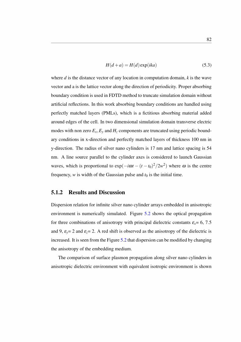
Dispersion relation for infinite silver nano cylinder arrays embedded in anisotropic
environment is numerically simulated. Figure 5.2 shows the optical propagation
for three combinations of anisotropy with principal dielectric constants εx= 6, 7.5
and 9, εy= 2 and εz= 2. A red shift is observed as the anisotropy of the dielectric is
increased. It is seen from the Figure 5.2 that dispersion can be modified by changing
the anisotropy of the embedding medium.
The comparison of surface plasmon propagation along silver nano cylinders in
anisotropic dielectric environment with equivalent isotropic environment is shown
83
0.2 0.25 0.3 0.35 0.4
Wave vector (2π/a)
0.11
0.12
0.13
0.14
0.15
0.16
Fre
qu
en
cy (
ωa
/2πc)
(9,2,2)
(7.5,2,2)
(6,2,2)
Figure 5.2: Dispersion of plasmon modes in silver dimer nano cylinder arrays em-bedded in anisotropic medium
in Figure 5.3. Simulations are repeated for different combinations of anisotropy. It
is seen that in each case the isotropic curve is red shifted from the corresponding
anisotropic curve.
84
0.18 0.2 0.22 0.24 0.26 0.28 0.3 0.32 0.34
Wave vector(2π/a)
0.09
0.1
0.11
0.12
0.13
0.14
0.15
0.16
Fre
qu
en
cy (
ωa
/2πc)
anisotropic
isotropic
(a)
0.18 0.2 0.22 0.24 0.26 0.28 0.3 0.32 0.34
Wave vector(2π/a)
0.08
0.1
0.12
0.14
0.16
Fre
qu
en
cy (
ωa
/2πc)
isotropic
anisotropic
(b)
0.18 0.2 0.22 0.24 0.26 0.28 0.3 0.32 0.34
Wave vector(2π/a)
0.08
0.09
0.1
0.11
0.12
0.13
0.14
0.15
Fre
qu
en
cy (
ωa
/2πc)
isotropic
anisotropic
(c)
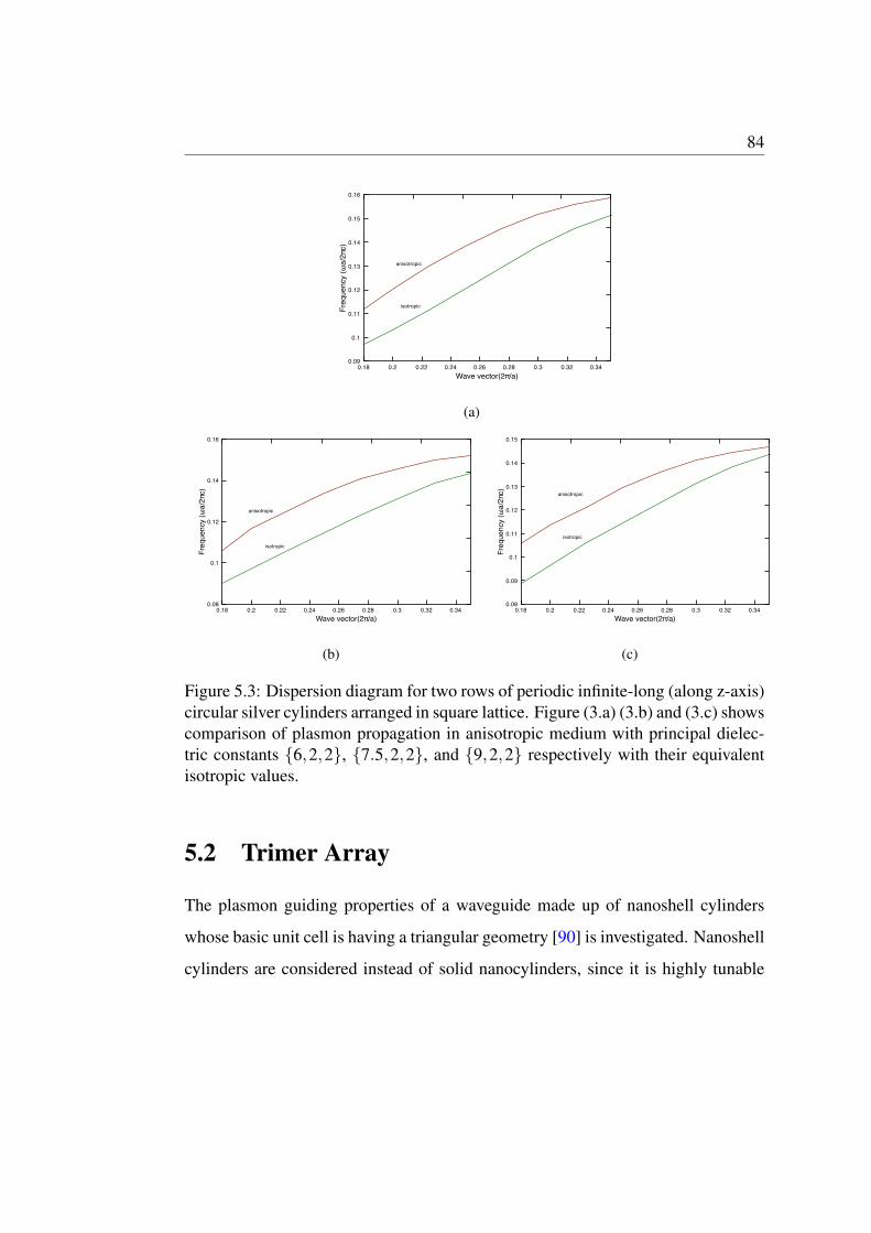
Figure 5.3: Dispersion diagram for two rows of periodic infinite-long (along z-axis)circular silver cylinders arranged in square lattice. Figure (3.a) (3.b) and (3.c) showscomparison of plasmon propagation in anisotropic medium with principal dielec-tric constants {6,2,2}, {7.5,2,2}, and {9,2,2} respectively with their equivalentisotropic values.
5.2 Trimer Array
The plasmon guiding properties of a waveguide made up of nanoshell cylinders
whose basic unit cell is having a triangular geometry [90] is investigated. Nanoshell
cylinders are considered instead of solid nanocylinders, since it is highly tunable
85
depending on the dimensions of the cylinder and material parameters. The prop-
agation of plasmon modes through a realistic well defined finite structure which
supports sub-wavelength wave propagation with reduced losses is studied, using
Finite Element Method (FEM) using commercial software COMSOL and with Fi-
nite Difference Time Domain (FDTD) method using MEEP.
5.2.1 Simulation Model
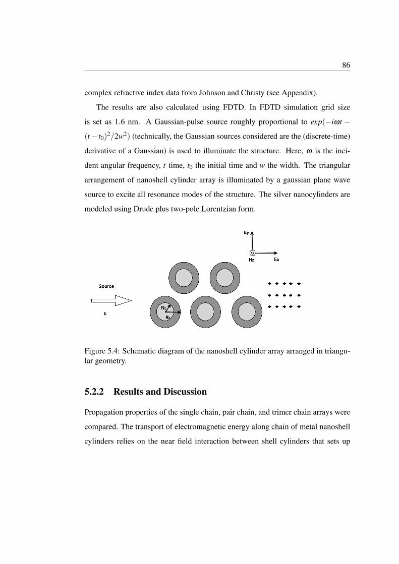
The schematic diagram of the nanoshell cylinder array arranged in triangular geom-
etry is shown in Fig. 5.4. The waveguide is illuminated with a transverse magnetic
(TM) polarized plane wave in order to excite all resonance modes of the structure
within UV, visible and IR region of the spectrum. The direction of the incident
electric field E is perpendicular to k and parallel to the plane of incidence. The
structure considered here consists of a total of forty nanoshell cylinders. The unit
cell consists of infinitely long nanoshell cylinders arranged at the vertices of an
equilateral triangle with the cylinder axis along Z direction. Each shell cylinders
consists of a dielectric core cylinder surrounded by a metallic (silver) shell cylin-
der. The shell thickness of the cylinder shell is the difference between the particle
radius (R1) and the core radius (R2). In this chapter, all the shell cylinders are con-
sidered to be identical. The plasmon resonances of nanocylinders with dimensions
down to 2 nm can be studied using Maxwell’s theory [91, 92]. The dimension of
shell cylinders and the interparticle distance considered are well above the quan-
tum regime. The scattering properties of particles having these dimensions are well
explained by Maxwell’s theory. Throughout this study, the interparticle distance
is fixed at 130 nm. The metal (silver) is modeled using the frequency dependent
86
complex refractive index data from Johnson and Christy (see Appendix).
The results are also calculated using FDTD. In FDTD simulation grid size
is set as 1.6 nm. A Gaussian-pulse source roughly proportional to exp(−iωt −
(t− t0)2/2w2) (technically, the Gaussian sources considered are the (discrete-time)
derivative of a Gaussian) is used to illuminate the structure. Here, ω is the inci-
dent angular frequency, t time, t0 the initial time and w the width. The triangular
arrangement of nanoshell cylinder array is illuminated by a gaussian plane wave
source to excite all resonance modes of the structure. The silver nanocylinders are
modeled using Drude plus two-pole Lorentzian form.
Figure 5.4: Schematic diagram of the nanoshell cylinder array arranged in triangu-lar geometry.
5.2.2 Results and Discussion
Propagation properties of the single chain, pair chain, and trimer chain arrays were
compared. The transport of electromagnetic energy along chain of metal nanoshell
cylinders relies on the near field interaction between shell cylinders that sets up
87
coupled dipole or higher order modes. This type coupling is similar to the process
of resonant energy transfer observed in systems containing closely spaced optically
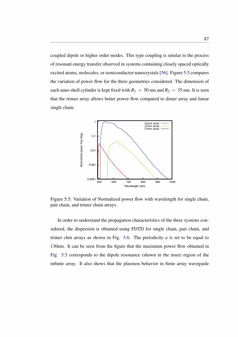
excited atoms, molecules, or semiconductor nanocrystals [56]. Figure 5.5 compares
the variation of power flow for the three geometries considered. The dimension of
each nano shell cylinder is kept fixed with R1 = 50 nm and R2 = 35 nm. It is seen
that the trimer array allows better power flow compared to dimer array and linear
single chain.
Figure 5.5: Variation of Normalized power flow with wavelength for single chain,pair chain, and trimer chain arrays.
In order to understand the propagation characteristics of the three systems con-
sidered, the dispersion is obtained using FDTD for single chain, pair chain, and
trimer chin arrays as shown in Fig. 5.6. The periodicity a is set to be equal to
130nm. It can be seen from the figure that the maximum power flow obtained in
Fig. 5.5 corresponds to the dipole resonance (shown in the inset) region of the
infinite array. It also shows that the plasmon behavior in finite array waveguide
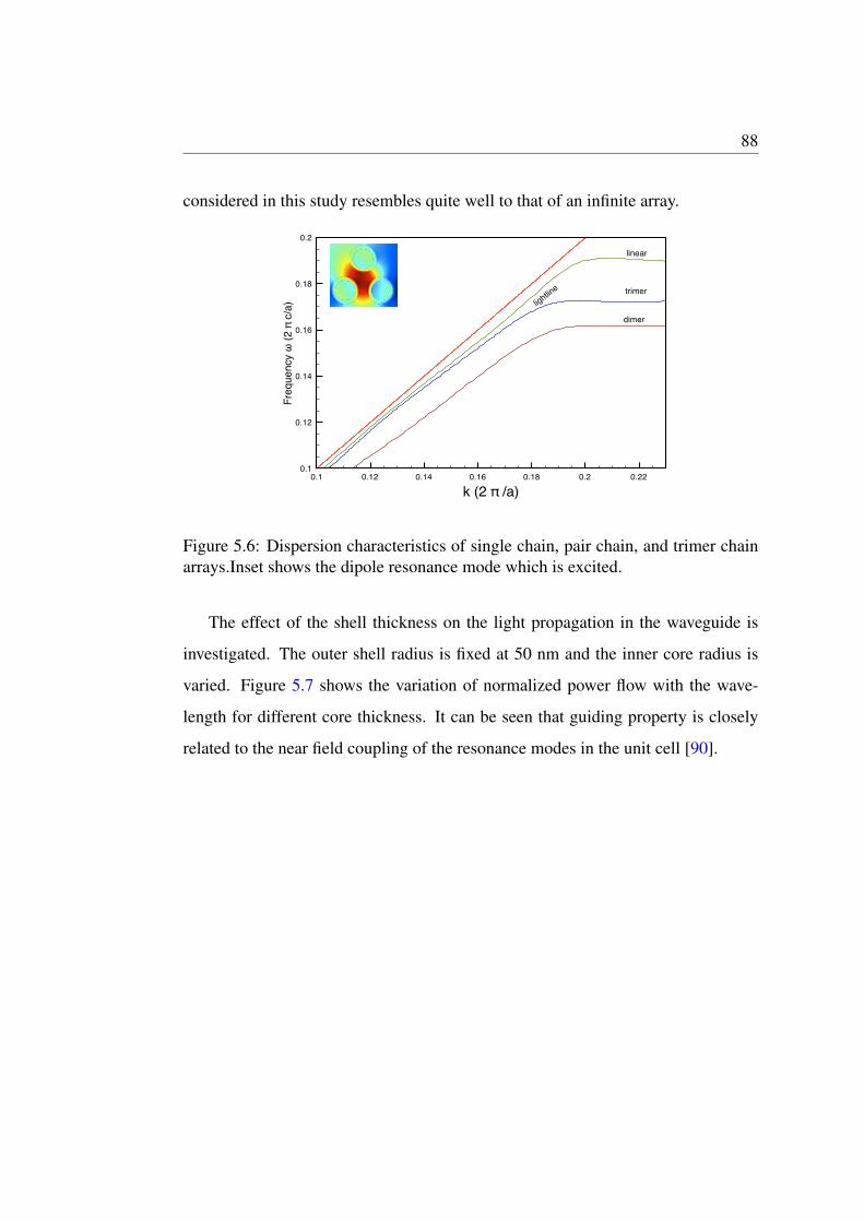
88
considered in this study resembles quite well to that of an infinite array.
0.1 0.12 0.14 0.16 0.18 0.2 0.22
k (2 π /a)
0.1
0.12
0.14
0.16
0.18
0.2
Fre
qu
en
cy ω
(2
π c
/a)
linear
dimer
trimer
lightlin
e
Figure 5.6: Dispersion characteristics of single chain, pair chain, and trimer chainarrays.Inset shows the dipole resonance mode which is excited.
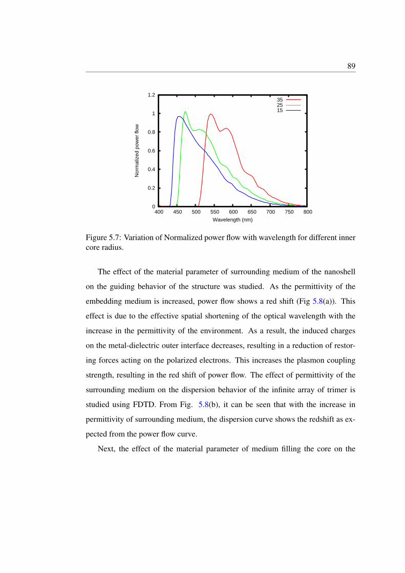
The effect of the shell thickness on the light propagation in the waveguide is
investigated. The outer shell radius is fixed at 50 nm and the inner core radius is
varied. Figure 5.7 shows the variation of normalized power flow with the wave-
length for different core thickness. It can be seen that guiding property is closely
related to the near field coupling of the resonance modes in the unit cell [90].
89
0
0.2
0.4
0.6
0.8
1
1.2
400 450 500 550 600 650 700 750 800
Nor
mal
ized
pow
er fl
ow
Wavelength (nm)
352515
Figure 5.7: Variation of Normalized power flow with wavelength for different innercore radius.
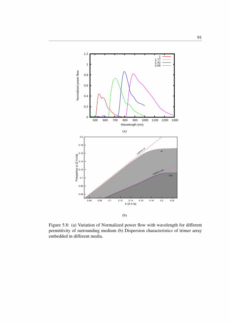
The effect of the material parameter of surrounding medium of the nanoshell
on the guiding behavior of the structure was studied. As the permittivity of the
embedding medium is increased, power flow shows a red shift (Fig 5.8(a)). This
effect is due to the effective spatial shortening of the optical wavelength with the
increase in the permittivity of the environment. As a result, the induced charges
on the metal-dielectric outer interface decreases, resulting in a reduction of restor-
ing forces acting on the polarized electrons. This increases the plasmon coupling
strength, resulting in the red shift of power flow. The effect of permittivity of the
surrounding medium on the dispersion behavior of the infinite array of trimer is
studied using FDTD. From Fig. 5.8(b), it can be seen that with the increase in
permittivity of surrounding medium, the dispersion curve shows the redshift as ex-
pected from the power flow curve.
Next, the effect of the material parameter of medium filling the core on the

90
guiding behavior of the structure was studied. The variation of normalized power
flow with wavelength for different permittivity of the core dielectric is shown in
Figures 5.9. The effect of the permittivity of the core medium is less compared
to that of the surrounding medium, surface area of the boundary between the two
media is less in comparison to latter case.
91
0
0.2
0.4
0.6
0.8
1
1.2
500 600 700 800 900 1000 1100 1200 1300
Nor
mal
ized
pow
er fl
ow
Wavelength (nm)
11.772.423.06
(a)
0.06 0.08 0.1 0.12 0.14 0.16 0.18 0.2 0.22
k (2 π /a)
0.06
0.08
0.1
0.12
0.14
0.16
0.18
0.2
Fre
qu
en
cy ω
(2
π c
/a) Lig
htline a
ir
Lightline 3.06
air
3.06
(b)
Figure 5.8: (a) Variation of Normalized power flow with wavelength for differentpermittivity of surrounding medium (b) Dispersion characteristics of trimer arrayembedded in different media.
92
0
0.2
0.4
0.6
0.8
1
1.2
500 550 600 650 700 750 800
Nor
mal
ized
pow
er fl
ow
Wavelength (nm)
11.772.423.06
Figure 5.9: Variation of Normalized power flow with wavelength for different per-mittivity of core.
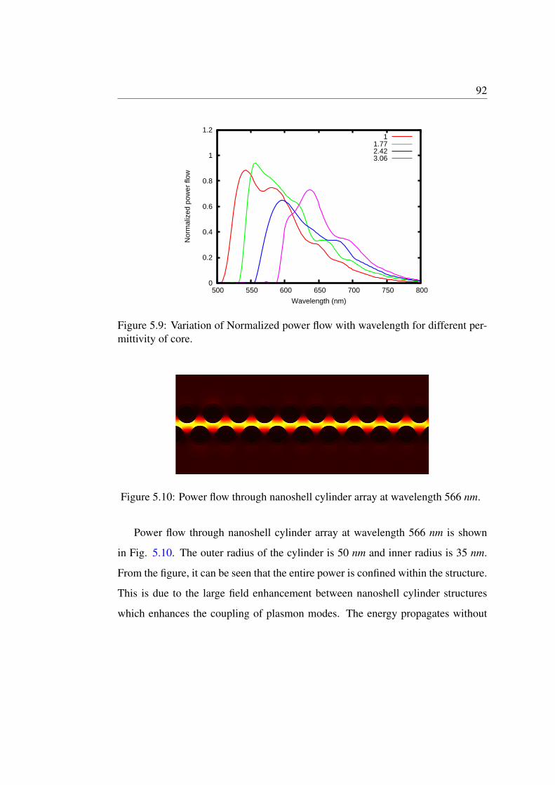
Figure 5.10: Power flow through nanoshell cylinder array at wavelength 566 nm.
Power flow through nanoshell cylinder array at wavelength 566 nm is shown
in Fig. 5.10. The outer radius of the cylinder is 50 nm and inner radius is 35 nm.
From the figure, it can be seen that the entire power is confined within the structure.
This is due to the large field enhancement between nanoshell cylinder structures
which enhances the coupling of plasmon modes. The energy propagates without
93
much loss through the structure, thus nanoshell cylinder array can provide optical
guidance confined in the region between the chains, which finds applications in
various integrated nano-optical waveguide devices.
5.3 Conclusion
A plasmonic waveguide formed by an array of periodic infinite long silver cylinders
at optical frequencies was modeled using FDTD method. It is shown that anisotropy
of the surrounding medium can change the plasmon polariton propagation in silver
nano cylinder arrays. This can have novel applications in the designs of waveguides,
small antenna, and efficient absorbers.
The near field optical properties of an array of silver nano shell cylinders ar-
ranged in triangular geometry is also studied using Finite Element Method. By
varying the surrounding dielectric environment, interparticle distance, radius of the
nanocylinders, the plasmon resonance is tuned across the UV, visible and near in-
frared spectral range. Field propagation can be enhanced using a trimer array of
nano shell cylinders compared to a pair array or linear single chain array. Surface
plasmon resonance and field propagation can also be controlled by changing the the
permittivities of the inner core as well as surrounding medium.