Embed Size (px)
Citation preview
114
5"Research is what I'm doing when I don't know what I'm doing."
Wernher Von Braun (1912-1977)
Chapter 5 - User interface
This chapter presents new user interface technology that I have designed and developed for
use with mobile outdoor AR systems. This user interface is used to control the previously
described AR working planes and construction at a distance techniques, and is implemented
in a mobile outdoor AR modelling application named Tinmith-Metro. The implementation of
the techniques described in this dissertation demonstrates their use, and allows different ideas
to be tested and iteratively refined through user feedback. Testing the techniques out in the
field has also given insights into more efficient methods after experimenting with early
prototypes. The user interface described in this chapter is designed to be implemented within
the limitations of current technology while still being intuitive to use. The solution developed
uses a pair of vision tracked pinch gloves that interact with a new menuing system, designed
to provide a cursor for AR working planes and command entry to switch between different
operations. The user requires feedback on the HMD while using the system, and so the design
of the display with its various on screen objects is discussed. To implement the full Tinmith-
Metro application, a large hierarchy of commands was created to control the various
modelling techniques and these are presented in a format similar to a user manual. This
chapter ends with a summary of a number of informal user evaluations that were used to
iteratively refine the interface.
5.1 Design rationale
Augmented and virtual reality both use the motion of the body to control the image that is
displayed to the user. While tracking the body is critical to rendering AR and VR displays,
Chapter 5 - User interface
115
fine grained manipulation and selection operations typically require the hands to intuitively
specify. The previously described Smart Scene [MULT01] and CHIMP [MINE96]
applications have intuitive user interfaces that involve the use of hand gestures supplied by
high quality tracking systems. These user interfaces implement many best practice techniques
for direct manipulation in VR that are desirable for modelling tasks. While outdoor AR is
similar and using these techniques is desirable, there are a number of unique problems
(discussed in Chapter 2) that require solutions. Previously discussed outdoor AR systems use
indirect style user interfaces involving tablets, keyboards, joysticks, trackballs, gyro mice, and
other hand-held devices but do not support direct manipulation operations. The user instead
steers a cursor across the display using indirect motions of the hands. Some devices such as
velocity-based inputs have a further level of indirection and so are even less intuitive to use.
Shneiderman [SHNE83] and Johnson et al. [JOHN89] both discuss how adding levels of
indirection may make user interfaces less intuitive to operate. Furthermore, any AR user
interface developed must use mobile technology so the user may roam freely in the outside
environment. It must take into account restrictions on size, performance, electric power
consumption, and weight.
I was initially inspired by the elegant combination of commands and pointing implemented
by Bolt in the Put-That-There system [BOLT80]. The user is able to point their hand toward
objects projected onto the walls and then speak commands to perform operations. The use of
menus by many other applications is an unintuitive abstraction that forces users to select
suitable options from a list, usually with the same input device. The direct command entry in
Put-That-There is similar to how people operate in the real world, and can be observed when
watching a supervisor explain an operation to a worker: “Pick up that brick and place it over
there”, while at the same time pointing with the hands to indicate exactly what object and
where to put it. Brooks also agrees and discusses how commands and operations should be
separated in interactive systems [BROO88].
Based on this initial inspiration from Bolt and Brooks, I have developed a user interface
involving the use of tracked gloves so the user can point at objects and interact with them in a
mobile outdoor AR system. Since the user is wearing gloves, there is no need for any other
devices and the hands are free to perform physical world tasks. Implemented using vision
tracking, the interface can locate the user’s hands in the field of view. Using optical methods
(discussed further in Chapter 7) is one of the only ways to perform tracking of the hands
outside, although the 3D accuracy is quite poor compared to indoor magnetic tracking. One
property of the optical tracker is that its 2D accuracy is quite good, and 2D cursors can be

Chapter 5 - User interface
116
calculated from the hand positions very easily. These 2D cursors are suitable for input to the
AR working planes techniques and used to perform interactions in 3D environments. Due to
poor distance and orientation detection, these values are not used to control the user interface.
The use of tracked gloves to perform selection and manipulation of objects is a very direct
user interface because natural hand gestures are used to express actions. Although the object
at a distance is not being touched directly, humans still intuitively understand this operation.
When talking with others, humans naturally point and understand these gestures even when
the object is very far away. Pierce et al. demonstrated a number of simple selection techniques
demonstrating this using image planes [PIER97].
Brooks suggested that commands and operations should be kept separate and so I have
included this important idea into the user interface. Many systems implementing direct
manipulation also make use of menus or other widgets that the user must reach out and grab.
These systems use the same cursors for both interaction and command entry, and these ideas
do not work well when implemented with poor tracking. Rather than having unreliable
command entry caused by poor tracking, I have developed an interface based on the pinching
of fingers to select commands from menus fixed to the display. The pinching of fingers is a
very reliable input that is easy to implement in any environment, and allows the hands to be
outside the field of view and untracked during command entry. The use of finger pinches
mapped directly to the menu also allows the same hand to perform simultaneous interaction
and command entry.
By separating the command interface from pointing, Brooks describes how the command
input method can be changed without affecting interaction. He also suggests that speech
recognition is a natural candidate for command selection, as used by Bolt in Put-That-There.
Johnson et al. also point out that the use of command interfaces such as speech input
encourages the user to think of the computer as an assistant or co-worker rather than a tool
[JOHN89]. While it would be interesting to explore the use of speech recognition for
command entry, the current software available to implement it is very CPU intensive. When
using a mobile computer there are limited resources available, and speech recognition would
prevent the rest of the AR system from functioning adequately. Problems such as lack of
accuracy and interference from noise (especially when outside) were common in older
systems, and although improvements have been made they have not been eliminated.
Currently this user interface does not implement speech recognition, but is designed to
support this and is discussed as a future area of research at the end of this chapter.
Chapter 5 - User interface
117
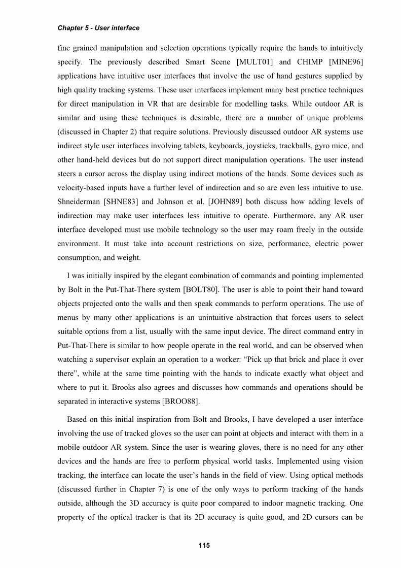
The user interface is made up of three components: a pointer based on the tracking of the
thumbs with a set of gloves worn by the user; command entry system where the user’s fingers
interact with a menu for performing actions; and an AR display that presents information back
to the user. The display for the interface is fixed to the HMD’s screen and presents up to ten
possible commands as menu options at any one time. Eight of these commands are mapped to
the fingers as depicted in Figure 5-1, and the user activates a command by pressing the
appropriate finger against the thumb. When an option is selected, the menu refreshes with the
next set of options that are available. Ok and cancel operations are activated by pressing the
fingers into the palm of the appropriate hand and are indicated in the topmost boxes of the
menu. The interaction cursors are specified using fiducial markers placed on the tips of the
thumbs, as shown in Figure 5-2. With this user interface, the user can perform AR working
planes, action at a distance, and construction at a distance techniques in mobile outdoor AR
environments.
5.2 Cursor operations
The concept of AR working planes and two example uses were presented in Chapter 3, one
for the manipulation of objects and the other for the creation of new vertices. AR working
planes are designed to support interactions at large distances and only 2D input is required,
simplifying the tracking requirements. Using the previously mentioned gloves, fiducial
Figure 5-1 Each finger maps to a displayed menu option, the user selects one by pressing the appropriate finger against the thumb
Chapter 5 - User interface
118
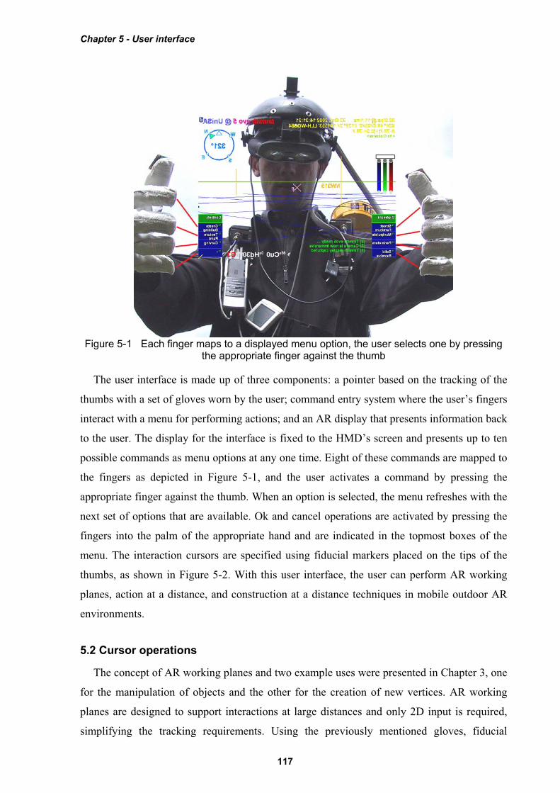
markers are placed on the thumbs to provide 3D tracking information using the ARToolKit
[KATO99]. Due to the implementation of ARToolKit, the 6DOF accuracy can be quite poor
but overlaid objects always appear to register with the targets. When the 3D coordinates from
the tracker are projected onto the image plane of the display, an accurate 2D cursor can be
obtained, as displayed in Figure 5-2. With the availability of suitable tracking, the user
interface contains cursors for both hands as well as a head cursor fixed to the centre of the
HMD. Each operation is implemented using varying combinations of these input cursors
depending on what is most appropriate. This section describes the implementation of one,
two, and zero-handed AR working planes techniques with examples demonstrating their use
outdoors.
To simplify manipulation tasks for the user, operations such as translate, rotate, and scale
are implemented using separate commands. This is on the assumption that the user will wish
to work with certain degrees of freedom without affecting others. Researchers such as
Hinckley [HINC94a] and Masliah and Milgram [MASL00] have demonstrated that users have
difficulty controlling both the position and orientation of the hands at the same time.
Constrained manipulation is also useful when poor tracking is used, so that other degrees of
freedom are not affected when simple changes are made. Manipulation handles (as used in
many previous 2D and 3D systems) are not used since they would be difficult to grab with the
poor tracking available. The user instead activates the desired manipulation operation with a
menu command and may grab any visible part of the object. This is also more intuitive since
objects in the physical world can be moved by grabbing any part of the object.
Figure 5-2 Immersive AR view, showing gloves and fiducial markers, with overlaid modelling cursor for selection, manipulation, and creation

Chapter 5 - User interface
119
5.2.1 One-handed interaction
Users may perform selection operations using a single hand controlling the 2D cursor. The
cursor is projected into the environment and intersected against the nearest object, similar to
the image plane techniques described by Pierce et al. [PIER97]. The object closest to the user
will be selected, placed into a selection buffer, and rendered transparently in a selection
colour for user feedback. Since the most common operations performed by users only involve
single objects, the implementation has been streamlined so that selection is automatically
performed when a manipulation command is activated.
To operate on many objects simultaneously, the user can select several objects and collect
them together into a selection buffer. When a manipulation task is then specified by the user,
they may select any object that is a part of the collection and then all objects will be used as
inputs. The ability to collect objects together is also useful for specifying operations such as
CSG where two inputs are required and both may contain multiple objects. Multiple objects
are currently collected together by selecting each object, although other techniques such as
two-handed rubber banding are simple to implement if required. To support modelling, an
arbitrary number of selection buffers may be stored in a circular list for later use. Overall
then, a modelling session may have a number of selection buffers (with one being active), and
each buffer contains collections of objects that must all be operated on together. Selection
buffers are similar to groups used in drawing editors, except no changes to the scene graph are
made to express this relationship. Each selection buffer is represented using a different
transparent colour to assist the user with identifying groupings. The active selection buffer
may be nominated by cycling through the available list or selecting an object that is part of the
desired selection buffer. Within a selection buffer, references to objects are also stored in a
circular list, with one object nominated as the last object. When a new object is added to the
selection buffer it will become the new last object, and extra commands are provided to
operate on only the last object instead of the entire selection buffer. The last object pointer is
useful for performing a type of undo to allow objects to be deleted in the order of creation.
Direct manipulation-based translation operations may be performed by the user with a
single hand. At the start of the operation, the user selects an object (and automatically any
other sibling objects which are part of the same selection buffer, if any) and an AR working
plane is created using head-relative coordinates with normal pointing toward the user, located
at the point of intersection with the object. As the user’s hand moves, the cursor is
continuously projected onto the AR working plane and used to offset the object accordingly,
performing translation and maintaining the same object to user distance. If the user moves
Chapter 5 - User interface
120
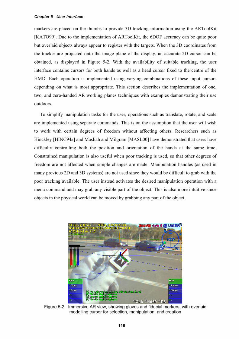
their body during the translation operation then the object will be moved in the same direction
as this motion. If the user changes their head direction then the object will rotate around with
the user’s head. Figure 5-3 shows an animation of a typical translation operation with a virtual
tree being directly manipulated across the landscape by the user’s hand and head motion.
Instead of using head-relative coordinates, the AR working plane could also be defined in
world, location, or body-relative coordinates to support different motion constraints. The
properties of AR working planes relative to these different coordinate systems were described
previously in Chapter 3.
Using AR working planes, the hand tracker and 2D cursor may also be used to project 3D
vertices. Chapter 4 described a number of techniques involving the placement of vertices for
the carving of objects and creating surfaces of revolution. When these techniques are
activated, an appropriate AR working plane is created and the user can place vertices onto the
plane using finger pinch commands.
5.2.2 Two-handed interaction
The AR working planes scale and rotate operations require more inputs than the translation
operation because an axis to scale or rotate about must be defined along with the adjustment
vector. Scale and rotate may be performed more naturally through the use of two-handed
input, which has been shown to improve performance and accuracy for users. Two-handed
input techniques were first pioneered by Buxton and Myers in a study using 2D environments
[BUXT86], and then discussed in terms of 3D environments in a survey paper by Hinckley et
al. [HINC94a]. Sachs et al. found that using a tracked tablet in one hand and a pen in the other
was more natural than having a fixed tablet and one-handed input [SACH91]. Zeleznik et al.
presented some two-handed 3D input methods for desktop applications, of which some are
implemented here [ZELE97]. These previous works all demonstrate that by using the non-
1 2 3 4
5 6 7 8Figure 5-3 Translation operation applied to a virtual tree with the user’s hands
Chapter 5 - User interface
121
dominant hand as an anchor, the dominant hand can accurately specify operations relative to
this. Scaling may be performed by stretching the object with the two hands. Instead of using
the orientation of the hand, rotation may be performed by using the angle between the two
hands.
Scaling operations are initiated by selecting an object and any associated selection buffer
sibling objects with the non-dominant hand, and an AR working plane is created at the object
in head-relative coordinates. Since the operation begins immediately after the scale command
is issued, the non-dominant hand must be selecting the object and the dominant hand should
be in a suitable position to specify the new relative scale adjustment. Similar to translation,
the AR working plane could also be expressed in other coordinate systems to support different
scaling constraints. The AR working plane is then used to capture initial 3D coordinates for
the input cursors so that any relative changes can be applied to the object selected. Since the
scale operation is performed against an AR working plane, only the two dimensions
perpendicular to the surface normal of the AR working plane may be adjusted. This
implementation uses the head cursor as the scaling axis and relative changes in the distance
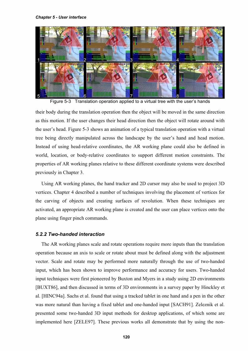
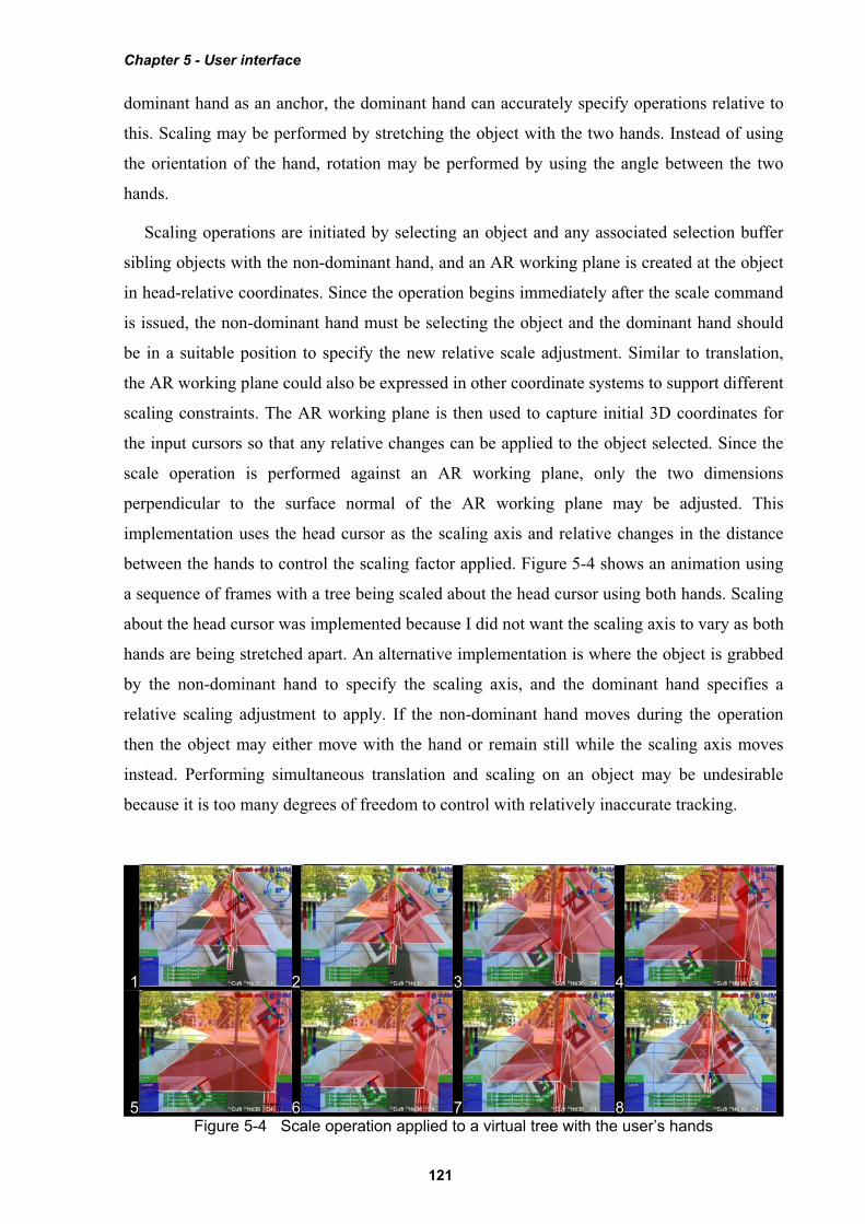
between the hands to control the scaling factor applied. Figure 5-4 shows an animation using
a sequence of frames with a tree being scaled about the head cursor using both hands. Scaling
about the head cursor was implemented because I did not want the scaling axis to vary as both
hands are being stretched apart. An alternative implementation is where the object is grabbed
by the non-dominant hand to specify the scaling axis, and the dominant hand specifies a
relative scaling adjustment to apply. If the non-dominant hand moves during the operation
then the object may either move with the hand or remain still while the scaling axis moves
instead. Performing simultaneous translation and scaling on an object may be undesirable
because it is too many degrees of freedom to control with relatively inaccurate tracking.
1 2 3 4
5 6 7 8Figure 5-4 Scale operation applied to a virtual tree with the user’s hands
Chapter 5 - User interface
122
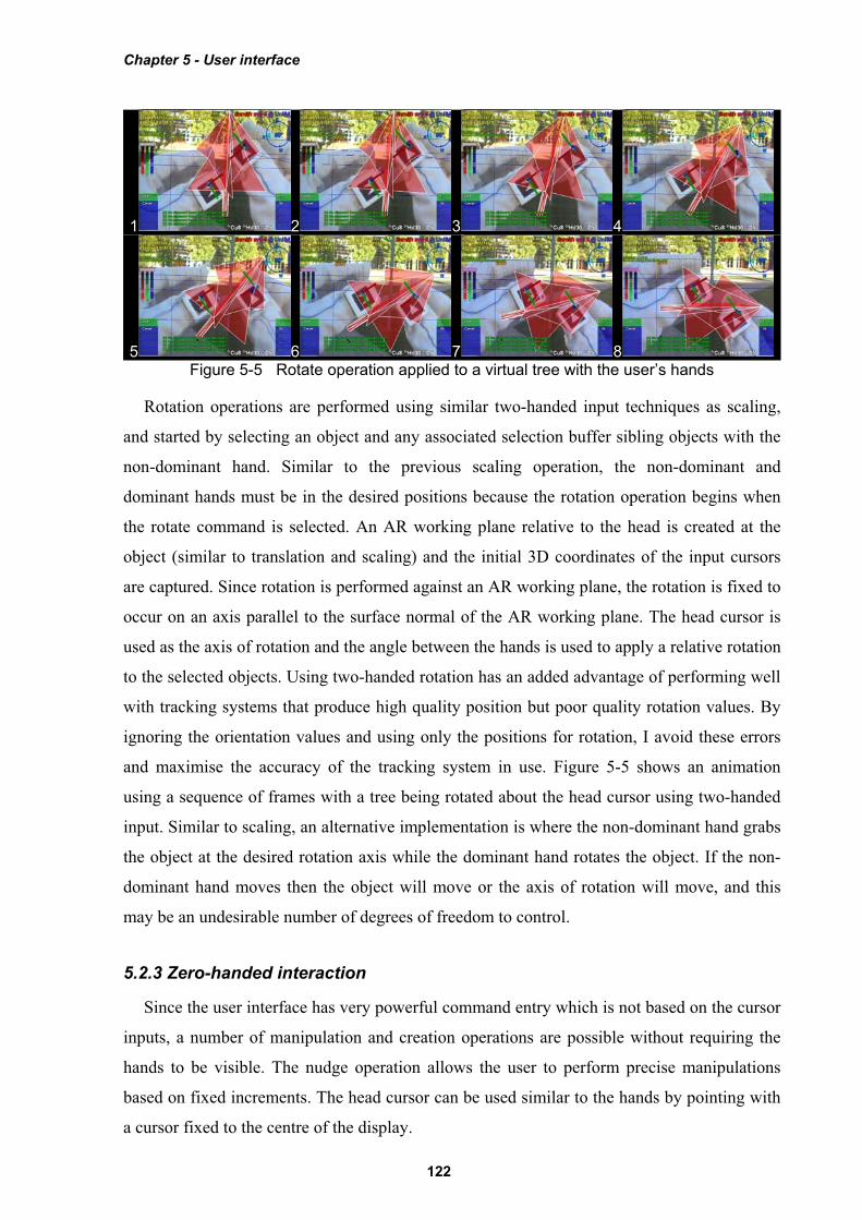
Rotation operations are performed using similar two-handed input techniques as scaling,
and started by selecting an object and any associated selection buffer sibling objects with the
non-dominant hand. Similar to the previous scaling operation, the non-dominant and
dominant hands must be in the desired positions because the rotation operation begins when
the rotate command is selected. An AR working plane relative to the head is created at the
object (similar to translation and scaling) and the initial 3D coordinates of the input cursors
are captured. Since rotation is performed against an AR working plane, the rotation is fixed to
occur on an axis parallel to the surface normal of the AR working plane. The head cursor is
used as the axis of rotation and the angle between the hands is used to apply a relative rotation
to the selected objects. Using two-handed rotation has an added advantage of performing well
with tracking systems that produce high quality position but poor quality rotation values. By
ignoring the orientation values and using only the positions for rotation, I avoid these errors
and maximise the accuracy of the tracking system in use. Figure 5-5 shows an animation
using a sequence of frames with a tree being rotated about the head cursor using two-handed
input. Similar to scaling, an alternative implementation is where the non-dominant hand grabs
the object at the desired rotation axis while the dominant hand rotates the object. If the non-
dominant hand moves then the object will move or the axis of rotation will move, and this
may be an undesirable number of degrees of freedom to control.
5.2.3 Zero-handed interaction
Since the user interface has very powerful command entry which is not based on the cursor
inputs, a number of manipulation and creation operations are possible without requiring the
hands to be visible. The nudge operation allows the user to perform precise manipulations
based on fixed increments. The head cursor can be used similar to the hands by pointing with
a cursor fixed to the centre of the display.
1 2 3 4
5 6 7 8Figure 5-5 Rotate operation applied to a virtual tree with the user’s hands
Chapter 5 - User interface
123
To perform accurate translation, scale, and rotate commands, an operation named nudging
is provided to operate in fixed increments and without requiring vision tracking. Nudging is
based on the use of arrow keys or other discrete controls for interaction which are commonly
used in 2D desktop-based modelling systems. The nudge move operation is used to offset the
object in one metre increments in any direction relative to the user (left, right, up, down,
towards, and away) and is useful in cases where the distance is known exactly or the user
cannot walk to drag the object. Scaling is performed similarly using fixed units in any of the
three axis directions or with the axes linked together to ensure uniform scaling. Rotation
implements fixed angular offsets and can rotate about any of the three axes individually. The
scale and rotate nudge operations also provide the ability to scale away from the user or rotate
around the ground plane normal, which cannot be performed normally since AR working
planes flattens these directions. Nudging does not require any input device tracking at all, and
so is useful when objects are too far to judge adjustments, or when tracking is of extremely
poor quality.
While the head cursor can be used to perform translation operations similar to those
implemented using the hands, the main use is for the placement of objects in the world. AR
working planes and orientation infinite planes may be projected from the head into the
environment, and the head cursor is used to define the direction from the user that this plane
will follow. Using the head cursor is an obvious way to project planes since the user is already
aligning objects by sighting along the head cursor cross in the centre of the display. The
placement of street furniture objects is also performed relative to the head cursor, with the
objects being placed either with zero distance at the user’s feet, or at a distance in front of the
user and placed in the direction of the head cursor. The head cursor is further used to define
surface normals for head-relative AR working planes definitions, with the normal being
calculated using the location of the user’s eye and the virtual head cursor in the centre of the
display.
5.3 Command entry
The cursor can be used to perform a range of powerful interaction operations, but a method
of specifying which operation to perform is required to support complex applications. This
section describes the hierarchical menu system I have developed to support a large number of
commands. As previously mentioned, finger pinches on the gloves are utilised to control the
menu system, allowing the user to select other menus and specify commands. Since no
tracking is required the user can hold their hands anywhere they desire, and there is no need to
dock the cursor onto menu options for selection. This especially increases the speed of
Chapter 5 - User interface
124
command entry under poor tracking conditions. A menu-based system was chosen as a simple
way of grouping common tasks to reduce searching time and form the basis for a command
entry system. Having a logical and efficient layout of menu options is also critical to making
it intuitive for users. This section compares the design of the menu system against a number
of other relevant AR and VR command entry systems to demonstrate its novel features.
5.3.1 Menu design
This dissertation has presented the benefits of using hand pointing for interaction and so a
menu design that is compatible with this style of input is required. Using another 2D input
device would be cumbersome and force the user to switch between different input
methodologies. Therefore the design of the menu system is not based on the traditional WIMP
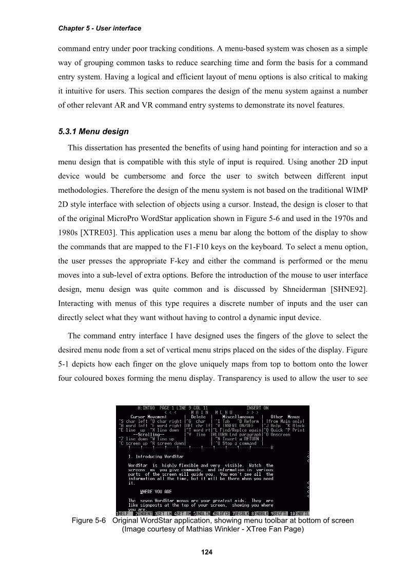
2D style interface with selection of objects using a cursor. Instead, the design is closer to that
of the original MicroPro WordStar application shown in Figure 5-6 and used in the 1970s and
1980s [XTRE03]. This application uses a menu bar along the bottom of the display to show
the commands that are mapped to the F1-F10 keys on the keyboard. To select a menu option,
the user presses the appropriate F-key and either the command is performed or the menu
moves into a sub-level of extra options. Before the introduction of the mouse to user interface
design, menu design was quite common and is discussed by Shneiderman [SHNE92].
Interacting with menus of this type requires a discrete number of inputs and the user can
directly select what they want without having to control a dynamic input device.
The command entry interface I have designed uses the fingers of the glove to select the
desired menu node from a set of vertical menu strips placed on the sides of the display. Figure
5-1 depicts how each finger on the glove uniquely maps from top to bottom onto the lower
four coloured boxes forming the menu display. Transparency is used to allow the user to see
Figure 5-6 Original WordStar application, showing menu toolbar at bottom of screen (Image courtesy of Mathias Winkler - XTree Fan Page)
Chapter 5 - User interface
125
the physical world through the menu, reducing visual clutter. The vertical placement of the
menu strips intentionally matches the orientation of the hands when held comfortably at rest
and when performing cursor operations. The direct mapping of finger pinches to menu
options helps the user to quickly select the correct menu node. In addition to the user’s eight
fingers available for selection, two extra menu items located on top of the existing list are
activated by pressing the fingers onto the palm and indicate major operations such as ok and
cancel. The menu display is always fixed to the screen of the HMD and is ready to perform
command entry regardless of the view direction or the position of the hands.
When the user selects a menu option, the system indicates the item by colouring it red, and
then on release an audible tone is given. Menu nodes can execute internal commands, move to
a deeper level in the menu, or both, and after performing these actions the display is updated
with the newly available options. When a task is completed or cancelled, the menu returns
back to the top-level node to perform the next operation. An added feature from the
development process is that the menu can also be controlled using a traditional keyboard
similar to the WordStar interface described earlier. This is useful for debugging when
working indoors and for externally helping out a troubled user during a demonstration.
The command entry system has a task oriented nature, which is customised towards a
particular set of operations that are being performed. When a user enters a mode such as
carving, the menu does not return to the top-level but instead remains at the carving menu.
Various carving operations are then available with only a single press required to activate
them. At the completion of the carving task with the ok palm gesture, the menu returns back
to the top-level so the user can select another task. The alternative is that the user has to
navigate through many levels of a menu for each step in a task, which is highly inefficient.
Each task is represented using a node in the hierarchy, with each step stored as a child of the
parent task. When performing a particular task, only steps that are relevant at that time are
presented to the user, reducing clutter. Section 5.5 describes the layout of the Tinmith-Metro
menu tree, demonstrating how the commands are arranged to support a complex modelling
application. This hierarchy has been optimised to ensure that commonly performed tasks are
easily accessible to the user.
5.3.2 Related work
There has been a large body of previous work in the area of command entry for both VR
environments and wearable computers, some of which is possible to leverage for use in
Chapter 5 - User interface
126
mobile outdoor AR. This subsection compares some of the most relevant existing work
against the user interface described in this chapter.
As previously described, Bowman and Wingrave have developed a VR menu system that
also uses pinch gloves as an input device [BOWM01]. The top-level menu items are mapped
to the fingers on one hand and the second-level options to the fingers on the other hand. Using
the small finger, the user can cycle through extra options if more than three are available. This
technique is limited to a depth of two due to its design and does not scale easily to a large
number of commands. While Bowman and Wingrave’s use of finger mapping is similar to my
approach, my method (first described in [PIEK01b]) is superior because it allows a larger
number of commands and minimises the number of presses required to perform the desired
task.
In the outdoor AR domain, the original Touring Machine work by Feiner et al. utilised a
small tablet computer with a web browser interface to control the main system [FEIN97].
Other research with tablets is also performed in the Studierstube environment by Szalavari
and Gervautz [SZAL97] and extended later by Schmalstieg et al. [SCHM00] and Reitmayr
and Schmalstieg [REIT01a]. Both of these user interfaces are useable while mobile because
the tablets are compact devices that can be held in the hands. The disadvantage of these
interfaces is they are not hands free, and require the tablet to be the centre of the user’s
attention to operate. Using the tablet to manipulate objects in the 3D view is also a less direct
form of interaction and requires the user to divide their attention between the 3D view and the
tablet.
The N-fingers technique was created by Lehikoinen and Roykkee for mobile outdoor
navigation and context awareness using AR cues [LEHI01]. N-fingers uses gloves with
metallic contacts similar to pinch gloves, except the contacts are arranged in a diamond shape
in the middle of the fingers. This technique is primarily designed for scrolling through menus
and lists, since the diamond shape maps easily to a set of directional arrows. By mapping the
fingers to scrolling directions, the user can work with large lists of items but this also prevents
jumping directly to desired options in one press. Since N-fingers can only be used for
command entry, it requires another input technique to provide 3D interaction.
Blasko and Feiner present the use of a touchpad mouse for controlling a menu [BLAS02].
Instead of using the touchpad to control a relative mouse cursor, this interface uses the
absolute position of the fingers to select from menu options. Menu options are directly
selectable and so the user does not need to track the motion of a cursor or look at the hands,
making it ideal for wearable applications. With the number of menu options limited by the
Chapter 5 - User interface
127
user’s four fingers and the resolution of the touchpad, menu hierarchies are used to extend the
number of options that can be provided. Since the fingers must press against the touchpad
surface mounted on the body, the user cannot perform cursor manipulation with the same
hand as command selection.
The SKETCH system by Zeleznik et al. uses a gesture-based interface controlled by a 2D
mouse to draw 3D pictures [ZELE96]. Hand gestures are analysed to initiate various
commands such as selection, manipulation, and deletion. As previously discussed, gesture-
based input requires the use of fast and accurate tracking to capture the motions correctly.
There are also limits to the number of hand motions that can intuitively map to commands,
with the rest requiring the user to memorise them. With the availability of limited outdoor
tracking and a large number of abstract modelling concepts, higher-level approaches such as
menus were chosen for the user interface.
5.4 Display interface
The user interface provides a wide range of information to the user apart from just cursors
and menus. Useable AR applications require other status information so that the user
understands the state of the application and the environment around them. This section
describes the display features that are used in the Tinmith-Metro mobile AR modelling
application.
5.4.1 Screen overlay
When viewing virtual objects outdoors, a 3D view registered with the physical world using
tracking devices is required for the AR overlay. This overlay contains virtual objects such as
buildings and trees that appear to exist in the physical world. The renderer also embeds other
information into this view to improve the user’s situational awareness. Shadows are rendered
underneath objects to indicate their height relative to the ground plane. A 10 metre by 10
metre grid with a 100 square metre size is overlaid on the ground plane to indicate how far
objects are away from the user. Tick marks with labels are placed every 15 degrees onto the
horizon to indicate directions and provide steering cues.
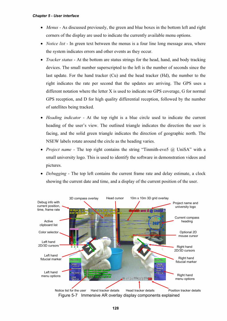
Other 2D information is fixed to the HMD using screen-relative coordinates and is overlaid
on top of the 3D view. 2D information is used to indicate the status of the system to the user
and can be selectively turned on an off. Figure 5-7 depicts the placement of the various
display components described below:
Chapter 5 - User interface
128
Menus - As discussed previously, the green and blue boxes in the bottom left and right
corners of the display are used to indicate the currently available menu options.
Notice list - In green text between the menus is a four line long message area, where
the system indicates errors and other events as they occur.
Tracker status - At the bottom are status strings for the head, hand, and body tracking
devices. The small number superscripted to the left is the number of seconds since the
last update. For the hand tracker (Cu) and the head tracker (Hd), the number to the
right indicates the rate per second that the updates are arriving. The GPS uses a
different notation where the letter X is used to indicate no GPS coverage, G for normal
GPS reception, and D for high quality differential reception, followed by the number
of satellites being tracked.
Heading indicator - At the top right is a blue circle used to indicate the current
heading of the user’s view. The outlined triangle indicates the direction the user is
facing, and the solid green triangle indicates the direction of geographic north. The
NSEW labels rotate around the circle as the heading varies.
Project name - The top right contains the string “Tinmith-evo5 @ UniSA” with a
small university logo. This is used to identify the software in demonstration videos and
pictures.
Debugging - The top left contains the current frame rate and delay estimate, a clock
showing the current date and time, and a display of the current position of the user.
3D compass overlay Debug info with current position, time, frame rate
Active clipboard list
Color selector
Left hand 2D/3D cursors
Left hand menu options Right hand
menu options
Right hand 2D/3D cursors
Current compass heading
Project name and university logo
Hand tracker details Position tracker details Head tracker details Notice list for the user
Right hand fiducial marker
Left hand fiducial marker
10m x 10m 3D grid overlay
Optional 2D mouse cursor
Head cursor
Figure 5-7 Immersive AR overlay display components explained
Chapter 5 - User interface
129
Clipboard list - Each clipboard is represented as a string with an id number and colour
value used for objects that are part of the clipboard. The names of objects contained
within are listed underneath the clipboard name.
Colour selector - The cursors can be moved through an invisible cube in the view
frustum where XYZ directions map to RGB values on a colour cube. The slider bars
indicate the contribution of each colour and above this is a small rectangle showing the
final colour. This colour can be applied to the surfaces of objects being modelled.
Cursor overlays - The vision tracking system produces 3D output that is used to
overlay a 3D axis object onto each marker. This axis object is then flattened against
the display and used to produce 2D cursors that may then be used with AR working
planes. A 2D head cursor is fixed to the centre of the display representing the direction
that the user is looking. An optional trackball mouse may be used for debugging to
provide a cursor instead of the gloves.
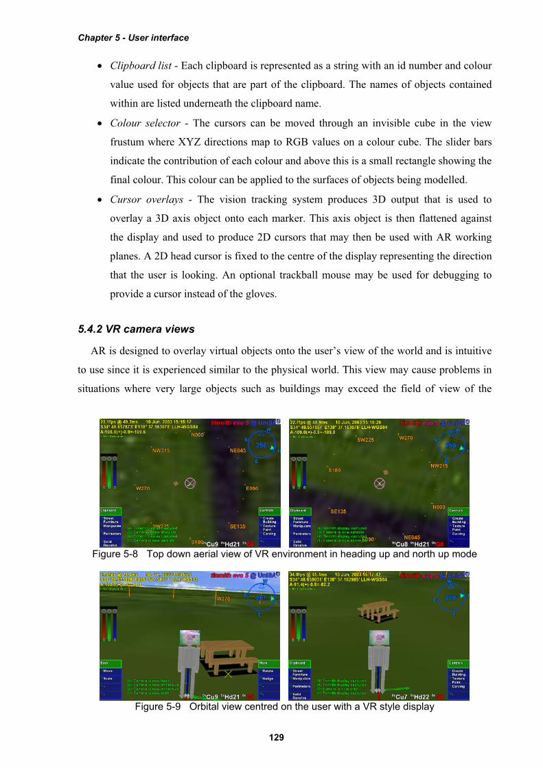
5.4.2 VR camera views
AR is designed to overlay virtual objects onto the user’s view of the world and is intuitive
to use since it is experienced similar to the physical world. This view may cause problems in
situations where very large objects such as buildings may exceed the field of view of the
Figure 5-8 Top down aerial view of VR environment in heading up and north up mode
Figure 5-9 Orbital view centred on the user with a VR style display

Chapter 5 - User interface
130
display, objects may be too distant to clearly view, or other objects may be occluding an
object of interest. The immersive view restricts the user if it is impractical or impossible for
the user to move to a new viewing position. In these cases, it is more useful to work in an
external VR style view (such as orbital view by Chung [CHUN92] and Koller et al.
[KOLL96]) where the user sees a view of the virtual world from an external perspective. The
advantages of external views are also discussed by Brooks, who mentions that users find a
local map of the world useful to show where they are, what they are looking at, and to build a
mental model for navigation [BROO88]. In the external views I have implemented, the
ground and sky are both rendered using texture maps so that the user understands they are
looking at a fully virtual view and are no longer immersive. Since the external view is
designed to be used while wearing the HMD outdoors, the body of the user is shown in the
centre of the display and motion about the physical world is updated in real-time. Top down
views such as that shown in Figure 5-8 provide an aerial perspective of the area, with north up
mode being fixed while heading up mode rotates the map in the direction the user is looking.
Orbital views such as that shown in Figure 5-9 link all 3DOFs of head rotation to orbiting
motions at a fixed distance around the user. Other views such as that shown in Figure 5-12 are
fixed relative to the body location so that it is not affected by rotation. These external views
are generally only used while stationary because the physical world is completely blocked out
and the user may not be able to safely move. The user is able to adjust the camera view using
body position or head rotation (as discussed previously) but not hand gestures, and can freely
switch between immersive and a number of pre-programmed external views using menu
commands.
5.4.3 Video overlay
The simplest form of AR is optically-based, where the system only draws in the AR detail
with the rest of the display remaining black for the physical world to be viewed in the HMD.
In order to improve accuracy and achieve higher quality images, my implementations have
switched from using optical overlay to video overlay (both of which are described in Chapter
2). All of the pictures presented in this dissertation of the final working system were captured
using video AR. Performing video overlay is more complicated than in the optical case, and
the computer needs to capture the video from a head mounted camera, render this to the
display, and then overlay the 3D and 2D graphics on top to produce the final output for the
HMD. The implementation still contains the ability to switch to optical overlay, but this is
rarely used.
Chapter 5 - User interface
131
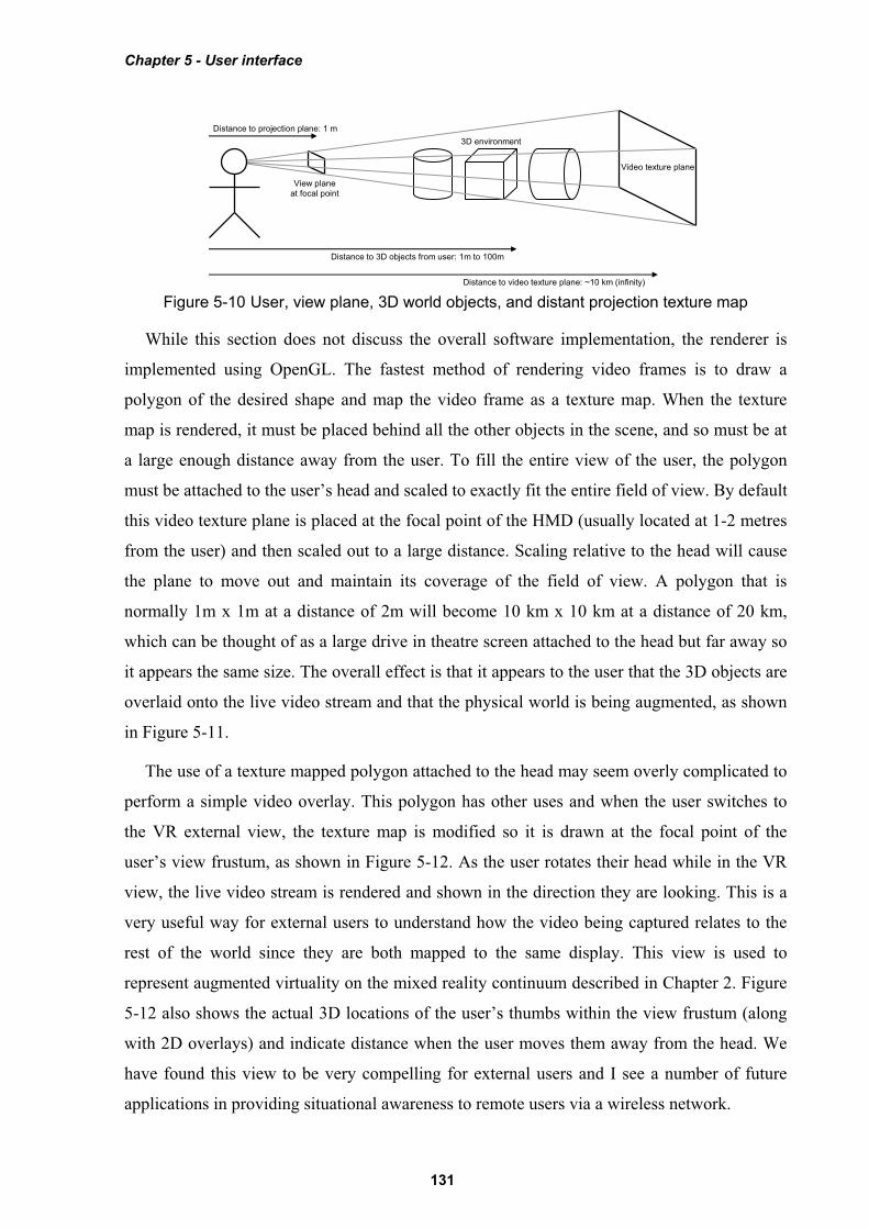
While this section does not discuss the overall software implementation, the renderer is
implemented using OpenGL. The fastest method of rendering video frames is to draw a
polygon of the desired shape and map the video frame as a texture map. When the texture
map is rendered, it must be placed behind all the other objects in the scene, and so must be at
a large enough distance away from the user. To fill the entire view of the user, the polygon
must be attached to the user’s head and scaled to exactly fit the entire field of view. By default
this video texture plane is placed at the focal point of the HMD (usually located at 1-2 metres
from the user) and then scaled out to a large distance. Scaling relative to the head will cause
the plane to move out and maintain its coverage of the field of view. A polygon that is
normally 1m x 1m at a distance of 2m will become 10 km x 10 km at a distance of 20 km,
which can be thought of as a large drive in theatre screen attached to the head but far away so
it appears the same size. The overall effect is that it appears to the user that the 3D objects are
overlaid onto the live video stream and that the physical world is being augmented, as shown
in Figure 5-11.
The use of a texture mapped polygon attached to the head may seem overly complicated to
perform a simple video overlay. This polygon has other uses and when the user switches to
the VR external view, the texture map is modified so it is drawn at the focal point of the
user’s view frustum, as shown in Figure 5-12. As the user rotates their head while in the VR
view, the live video stream is rendered and shown in the direction they are looking. This is a
very useful way for external users to understand how the video being captured relates to the
rest of the world since they are both mapped to the same display. This view is used to
represent augmented virtuality on the mixed reality continuum described in Chapter 2. Figure
5-12 also shows the actual 3D locations of the user’s thumbs within the view frustum (along
with 2D overlays) and indicate distance when the user moves them away from the head. We
have found this view to be very compelling for external users and I see a number of future
applications in providing situational awareness to remote users via a wireless network.
Distance to projection plane: 1 m
Distance to video texture plane: ~10 km (infinity)
Distance to 3D objects from user: 1m to 100m
Video texture plane
3D environment
View plane at focal point
Figure 5-10 User, view plane, 3D world objects, and distant projection texture map

Chapter 5 - User interface
132
5.5 Tinmith-Metro modelling application
The user interface design is integrated into an example modelling application I have
developed, named Tinmith-Metro [PIEK01b] [PIEK03c]. This application implements AR
working planes, construction at a distance techniques, and the glove-based user interface
described in this dissertation. This section discusses some of the implementation specific
features that have been added to create a fully functional application. This is provided to give
an understanding of the number of commands provided and the user’s experience while
modelling. While this example implementation is quite extensive, it does not define actual
limitations and so many other features can be implemented within the framework discussed.
Figure 5-11 Immersive view of Tinmith-Metro with 3D cursor objects appearing to be floating over the incoming video image
Figure 5-12 External view of Tinmith-Metro with user’s body and 3D environment The projection video is forced close to the user in this view
Chapter 5 - User interface
133
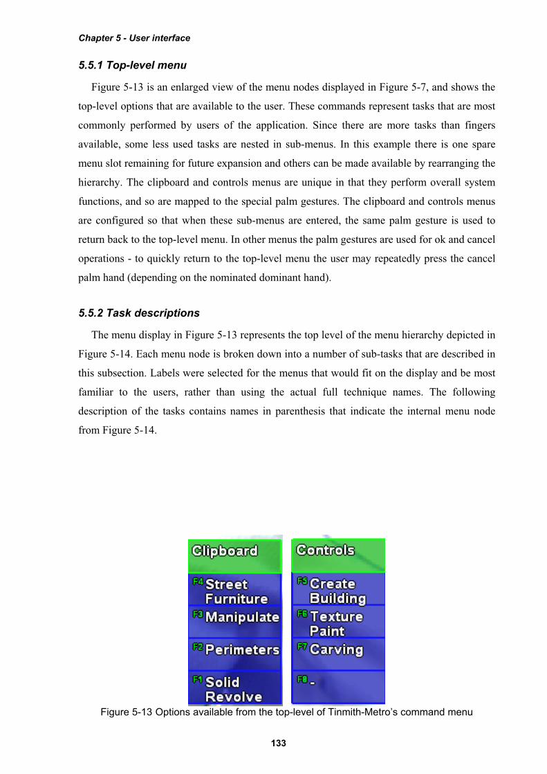
5.5.1 Top-level menu
Figure 5-13 is an enlarged view of the menu nodes displayed in Figure 5-7, and shows the
top-level options that are available to the user. These commands represent tasks that are most
commonly performed by users of the application. Since there are more tasks than fingers
available, some less used tasks are nested in sub-menus. In this example there is one spare
menu slot remaining for future expansion and others can be made available by rearranging the
hierarchy. The clipboard and controls menus are unique in that they perform overall system
functions, and so are mapped to the special palm gestures. The clipboard and controls menus
are configured so that when these sub-menus are entered, the same palm gesture is used to
return back to the top-level menu. In other menus the palm gestures are used for ok and cancel
operations - to quickly return to the top-level menu the user may repeatedly press the cancel
palm hand (depending on the nominated dominant hand).
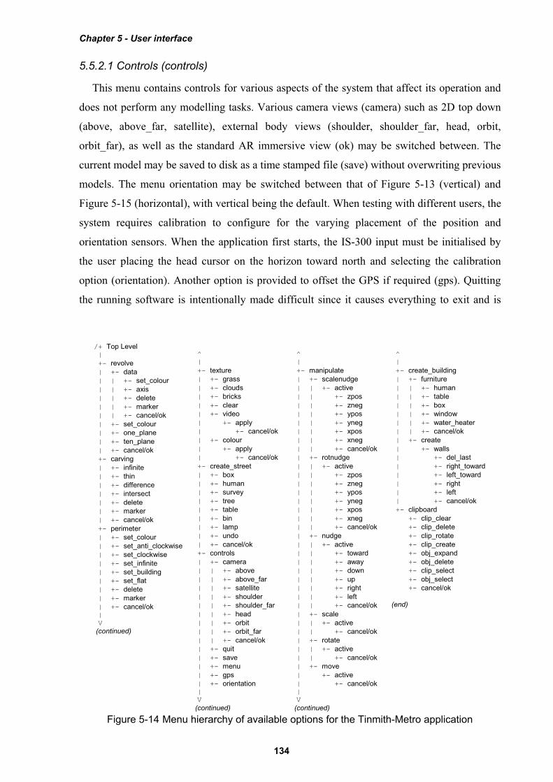
5.5.2 Task descriptions
The menu display in Figure 5-13 represents the top level of the menu hierarchy depicted in
Figure 5-14. Each menu node is broken down into a number of sub-tasks that are described in
this subsection. Labels were selected for the menus that would fit on the display and be most
familiar to the users, rather than using the actual full technique names. The following
description of the tasks contains names in parenthesis that indicate the internal menu node
from Figure 5-14.
Figure 5-13 Options available from the top-level of Tinmith-Metro’s command menu
Chapter 5 - User interface
134
5.5.2.1 Controls (controls)
This menu contains controls for various aspects of the system that affect its operation and
does not perform any modelling tasks. Various camera views (camera) such as 2D top down
(above, above_far, satellite), external body views (shoulder, shoulder_far, head, orbit,
orbit_far), as well as the standard AR immersive view (ok) may be switched between. The
current model may be saved to disk as a time stamped file (save) without overwriting previous
models. The menu orientation may be switched between that of Figure 5-13 (vertical) and
Figure 5-15 (horizontal), with vertical being the default. When testing with different users, the
system requires calibration to configure for the varying placement of the position and
orientation sensors. When the application first starts, the IS-300 input must be initialised by
the user placing the head cursor on the horizon toward north and selecting the calibration
option (orientation). Another option is provided to offset the GPS if required (gps). Quitting
the running software is intentionally made difficult since it causes everything to exit and is
/+ Top Level |
+- revolve | +- data | | +- set_colour | | +- axis | | +- delete | | +- marker | | +- cancel/ok | +- set_colour | +- one_plane | +- ten_plane | +- cancel/ok +- carving | +- infinite | +- thin | +- difference | +- intersect | +- delete | +- marker | +- cancel/ok +- perimeter | +- set_colour | +- set_anti_clockwise | +- set_clockwise | +- set_infinite | +- set_building | +- set_flat | +- delete | +- marker | +- cancel/ok | V (continued)
^ |
+- texture | +- grass | +- clouds | +- bricks | +- clear | +- video | +- apply | +- cancel/ok | +- colour | +- apply | +- cancel/ok +- create_street | +- box | +- human | +- survey | +- tree | +- table | +- bin | +- lamp | +- undo | +- cancel/ok +- controls | +- camera | | +- above | | +- above_far | | +- satellite | | +- shoulder | | +- shoulder_far | | +- head | | +- orbit | | +- orbit_far | | +- cancel/ok | +- quit | +- save | +- menu | +- gps | +- orientation | V
(continued)
^ |
+- manipulate | +- scalenudge | | +- active | | +- zpos | | +- zneg | | +- ypos | | +- yneg | | +- xpos | | +- xneg | | +- cancel/ok | +- rotnudge | | +- active | | +- zpos | | +- zneg | | +- ypos | | +- yneg | | +- xpos | | +- xneg | | +- cancel/ok | +- nudge | | +- active | | +- toward | | +- away | | +- down
| | +- up | | +- right | | +- left | | +- cancel/ok | +- scale | | +- active | | +- cancel/ok | +- rotate | | +- active | | +- cancel/ok | +- move | +- active | +- cancel/ok | V
(continued)
^ |
+- create_building | +- furniture | | +- human | | +- table | | +- box | | +- window | | +- water_heater | | +- cancel/ok | +- create | +- walls | +- del_last | +- right_toward | +- left_toward | +- right | +- left | +- cancel/ok +- clipboard +- clip_clear +- clip_delete +- clip_rotate +- clip_create +- obj_expand +- obj_delete +- clip_select +- obj_select +- cancel/ok
(end)
Figure 5-14 Menu hierarchy of available options for the Tinmith-Metro application
Chapter 5 - User interface
135
not performed very often. The option for quitting (quit) contains a nested menu that requires
alternating finger presses from each hand to prevent accidental activation.
5.5.2.2 Street furniture (create_street)
The creation of street furniture is performed with this menu, and various prefabricated
objects are mapped to options so that they may be created at the user’s current location. The
objects available are those that occur commonly in the outside environment such as boxes,
humans, survey markers, trees, tables, rubbish bins, and lamps. With larger collections of
objects, hierarchies may be used to organise them more efficiently. An unlimited undo option
(undo) is provided to delete the last object created. The ok gesture commits the active
selection buffer to the scene graph, while cancel deletes all the objects created.
5.5.2.3 Create building (create_building)
This menu implements techniques suitable for the modelling of houses and similar
structures. Street furniture style techniques (furniture) are provided for the placement of
objects such as humans, tables, boxes, windows, and water heaters. Orientation infinite planes
techniques from Chapter 4 are used for the capture of building structures (create). When
create mode is enabled, an infinite solid region is created around the user that will be used as
an input for future carving. The user then walks around the physical world, and may create
walls from the head cursor with normals pointing to the left (left) or right (right), as in Figure
3-9. The specification of the direction of the walls affects the side of the solid region carved
away with CSG since planes have an inside and outside. For cases where the user cannot align
themselves along a wall, world-relative planes may be created that face toward the user as in
Figure 3-10 at a fixed distance (left_toward, right_toward) but these are not normally used.
An unlimited undo option (del_last) is provided to delete the last wall entered and restore the
solid region. The ok gesture commits the building to the scene graph, while cancel deletes it.
5.5.2.4 Manipulate (manipulate)
This menu is used to perform all the manipulation operations described previously. Free
hand translation (move), rotation (rotate), and scaling (scale) as well as fixed unit translation
(nudge), rotation (rotnudge), and scaling (scalenudge) are provided. The cursor is used to
select an object and any associated selection buffers. When the user is satisfied with the new
transformation, it is committed to the scene graph with the ok gesture. The object can be
returned to its previous placement with the cancel gesture.
Chapter 5 - User interface
136
5.5.2.5 Texture paint (texture)
Polygons in the scene may have textures applied to the surface, either prefabricated or
captured using the head mounted camera. Existing sample textures are provided for grass,
bricks, and clouds. Textures may also be cleared from a polygon and reset to the original base
colour (clear). The colour widget may be used to specify any solid colour input by the user
(colour). When camera mode is selected (video), the system selects the polygon underneath
the glove cursor and prepares it for texture mapping. The final image is then captured from
the camera and mapped to the surface with the ok gesture, or aborted with the cancel gesture.
5.5.2.6 Perimeters (perimeter)
This menu implements the bread crumbs technique, used to mark out perimeters along the
ground. The user places down markers (marker) and after three or more markers are placed
down the system connects them together in real-time into a polygon. At any time the polygon
may be set to one of three specified extrusion thicknesses from the ground plane: a thin
slivered polygon (set_flat), a 3 metre building (set_building), or an infinite height object
(set_infinite). The infinite height object is useful for objects that are not slivers or 3 metres
high and can be carved later on. The direction the polygon is marked affects whether the
polygon extrudes upwards or downwards, with upwards being nominated to be clockwise
(set_clockwise) or anti-clockwise (set_anti_clockwise). The current position of the hands and
the colour widget may be used to nominate the surface colour (set_colour). An unlimited undo
option (delete) is provided to delete the last marker entered. The ok gesture commits the final
shape to the scene graph, while cancel deletes it.
5.5.2.7 Carving (carving)
Existing objects in the system may be modified using the cursor projection carving
techniques described in Chapter 4. The user projects markers against the surface of an object
(marker), with the first marker being used to nominate the object to carve, and create a world-
relative AR working plane at the surface. If one marker is placed, a horizontal plane facing
upwards is used to cut off the top of the object. Two markers specify a plane at an angle to cut
off the top of the object. Three or more markers are connected into a polygon and extruded
into the object, removing all parts of the object that are outside this extrusion. As each marker
is placed the system shows in real-time the effect of the change so the user may immediately
verify its accuracy. The length of the extrusion is normally infinite (infinite) but may be
switched at any time to being a thin sliver (thin) to carve slight surface features. The CSG
carving operation applied may be switched between the default (intersect) and difference
which inverts the extrusion and removes everything inside the selection instead (difference).
Chapter 5 - User interface
137
An unlimited undo option (delete) is provided to delete the last marker and recalculate the
carved object. The ok gesture commits the final carved shape to the scene graph and deletes
the original inputs. The cancel gesture aborts the operation and restores the original inputs.
5.5.2.8 Solid revolve (revolve)
The surface of revolution technique from Chapter 4 is implemented in this menu option.
The user initially needs to create an AR working plane and this may be projected with the
head cursor (data) as the most common case (as in Figure 3-9), or placed pointing toward the
user (as in Figure 3-10) at 1 metre away (one_plane) or 10 metres away (ten_plane). Once the
plane is created, the user can project markers against this plane (marker) using the cursor. At
any time the user may also specify the location of a vertical axis of rotation (axis) on the AR
working plane. With an axis of rotation specified the system will calculate the surface of
revolution and provide real-time updates as changes are made. The current position of the
hands and the colour widget may be used to nominate the surface colour at any time
(set_colour). An unlimited undo option (delete) is provided to delete the last marker entered.
The ok gesture commits the final shape to the scene graph, while cancel deletes it.
5.5.2.9 Clipboard (clipboard)
Clipboards have been previously described as selection buffers and provide collections of
inputs to modelling tasks. Working with these buffers is normally transparent to the user since
most tasks are performed with a single object and the system automatically sets up temporary
selection buffers. When the user desires to work with collections of objects, this menu is used
to gather multiple objects into selection buffers.
A new selection buffer is created and made active when a user nominates an unselected
object (obj_select). If an object is nominated that is already part of another selection buffer it
will be transferred to the current buffer. The alternative is to select a buffer (clip_select) by
nominating an object, and the buffer containing this object will be made active. If no buffer is
active then one will be created and the object added to it. New selection buffers may also be
created and made active without the selection of an object (clip_create).
The entire list of objects in a buffer may be deselected (clip_clear) or deleted from the 3D
world (clip_delete). As previously discussed, selection buffers maintain a circular list with a
pointer indicating the last object that was added. The circular list may be rotated (clip_rotate)
to shift a different object to being last. The last object in the active selection buffer may be
deleted from the 3D world (obj_delete). Since the system supports a hierarchy of models, the
selected object may not be at the desired level in the hierarchy. The last object added to the
Chapter 5 - User interface
138
buffer may be expanded (obj_expand) and the selection is adjusted to include the geometry at
the next level up in the hierarchy.
5.6 Informal user evaluations
The user interface was developed using an iterative design approach to take initial ideas
and then produce a more mature interface over time. At each stage of the design, the Tinmith-
Metro modelling application was used to test the interaction techniques with both myself as
well as novice users to gain their feedback. Brooks discusses insight into the design of user
interfaces and states that the uninformed and untested intuition of the designer is almost
always wrong [BROO88]. He suggests that interfaces must be refined with real users, and this
section discusses the studies performed and the changes that were made based on this
feedback.
5.6.1 Initial design
As discussed previously, I decided that the use of tracked pinch gloves for pointing and
command entry would be an efficient way of interacting with 3D objects in an outdoor AR
environment. The initial idea was to use gloves with metallic pads that would allow finger tip
to thumb, finger middle to thumb, and finger tip to palm inputs (similar to the Kitty hand
worn keyboard [KITT02]), with a total of 24 menu options (12 for each hand) available at any
time to select from. While allowing a large number of items at any particular time, I found
this design to be uncomfortable when I tried to select all 24 inputs. The presentation of 24
menu options on the display would also produce a confusing menu for conveying the
appropriate finger mappings and consume a large amount of screen area. To keep the menu
simple and within the limits of human dexterity, the design was reduced to having a single
menu node for each finger, and by pressing the fingers into the palm the menu would reset to
the top level. To present the layout of the menu, a horizontal strip of menu options was fixed
across the bottom of the display to correspond with the layout of the hands when they are laid
out flat. Figure 5-15 shows the layout of the user interface with the horizontal menu options
presented within a transparent green window.
5.6.2 May 2001 studies
The initial user interface implementation was designed to support the first Tinmith-Metro
modelling investigations [PIEK01b]. The first evaluation of the design with a functional
application was performed in May 2001. This evaluation was performed by my supervisor
and I, who were both very familiar with the Tinmith-Metro software and user interface. The
Chapter 5 - User interface
139
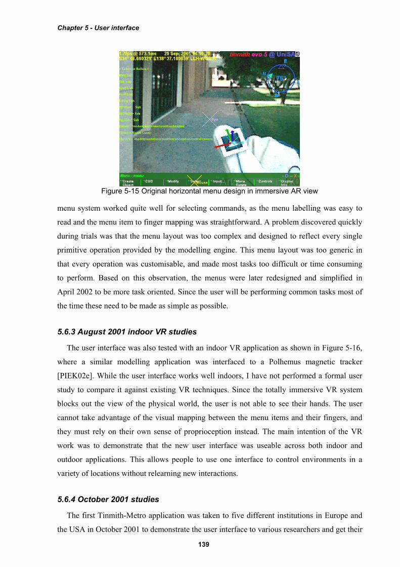
menu system worked quite well for selecting commands, as the menu labelling was easy to
read and the menu item to finger mapping was straightforward. A problem discovered quickly
during trials was that the menu layout was too complex and designed to reflect every single
primitive operation provided by the modelling engine. This menu layout was too generic in
that every operation was customisable, and made most tasks too difficult or time consuming
to perform. Based on this observation, the menus were later redesigned and simplified in
April 2002 to be more task oriented. Since the user will be performing common tasks most of
the time these need to be made as simple as possible.
5.6.3 August 2001 indoor VR studies
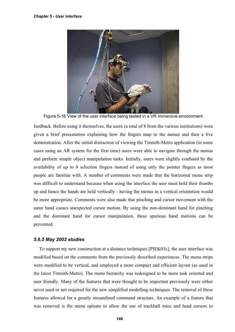
The user interface was also tested with an indoor VR application as shown in Figure 5-16,
where a similar modelling application was interfaced to a Polhemus magnetic tracker
[PIEK02e]. While the user interface works well indoors, I have not performed a formal user
study to compare it against existing VR techniques. Since the totally immersive VR system
blocks out the view of the physical world, the user is not able to see their hands. The user
cannot take advantage of the visual mapping between the menu items and their fingers, and
they must rely on their own sense of proprioception instead. The main intention of the VR
work was to demonstrate that the new user interface was useable across both indoor and
outdoor applications. This allows people to use one interface to control environments in a
variety of locations without relearning new interactions.
5.6.4 October 2001 studies
The first Tinmith-Metro application was taken to five different institutions in Europe and
the USA in October 2001 to demonstrate the user interface to various researchers and get their
Figure 5-15 Original horizontal menu design in immersive AR view
Chapter 5 - User interface
140
feedback. Before using it themselves, the users (a total of 8 from the various institutions) were
given a brief presentation explaining how the fingers map to the menus and then a live
demonstration. After the initial distraction of viewing the Tinmith-Metro application (in some
cases using an AR system for the first time) users were able to navigate through the menus
and perform simple object manipulation tasks. Initially, users were slightly confused by the
availability of up to 8 selection fingers instead of using only the pointer fingers as most
people are familiar with. A number of comments were made that the horizontal menu strip
was difficult to understand because when using the interface the user must hold their thumbs
up and hence the hands are held vertically - having the menus in a vertical orientation would
be more appropriate. Comments were also made that pinching and cursor movement with the
same hand causes unexpected cursor motion. By using the non-dominant hand for pinching
and the dominant hand for cursor manipulation, these spurious hand motions can be
prevented.
5.6.5 May 2002 studies
To support my new construction at a distance techniques [PIEK03c], the user interface was
modified based on the comments from the previously described experiences. The menu strips
were modified to be vertical, and employed a more compact and efficient layout (as used in
the latest Tinmith-Metro). The menu hierarchy was redesigned to be more task oriented and
user friendly. Many of the features that were thought to be important previously were either
never used or not required for the new simplified modelling techniques. The removal of these
features allowed for a greatly streamlined command structure. An example of a feature that
was removed is the menu options to allow the use of trackball mice and head cursors to
Figure 5-16 View of the user interface being tested in a VR immersive environment
Chapter 5 - User interface
141
perform manipulations on objects. These manipulation options were never used since the
gloves could perform the same tasks easier, and so the gloves are now permanently activated.
Another new feature is the extra green boxes at the top of the menu - rather than automatically
jumping to the top-level menu during a palm press, the menu shows the command for when
this gesture is used on each hand. A common use of the palm mapped gestures is for ok and
cancel operations, depending on which hand is nominated to be dominant by the user. As a
result of these changes, the interface was more user friendly and less reflective of the
implementation details. When I tested the new Tinmith-Metro outdoors, the improvements in
both the menu design and the construction at a distance techniques allowed me to more easily
model structures with greater complexity.
5.6.6 September 2002 augmented reality class
During September 2002 I helped present a two day course on AR technology at the
University of Tampere in Finland. As part of the course, the students were able to take the
Tinmith-Metro application outdoors and use the street furniture application to experience AR
modelling first hand. As in previous studies, the students were given a presentation about the
user interface and then shown a live demo to see the system operating. In this study
approximately 30 students participated and only 5 of them had any prior use of a HMD, with
none having any AR experience. The overall trial ran for just over 3 hours and each student
used the system for approximately 5 minutes, including time to don the equipment. Since the
users had no previous experience with AR systems, initially they were surprised and pleased
with the augmented overlay of 3D objects. The users were talked through the process of
creating several prefabricated objects and then manipulating them using the hands. While
most users required a minute or two to become familiar the interface and made several
mistakes, some users were very fast in adapting to the new interface.
Some users experienced difficulty with manipulating objects. The move task required the
use of both hands, one to control the menu for start and stop commands and the other to
perform the manipulation. This was discussed previously and implemented to avoid having
the same hand perform both tasks. I observed the users attempting to use the same hand to
select an object, drag it, and then release the fingers to drop it. The mental model employed
by the users was similar to that used with a desktop mouse dragging an object. Unfortunately
the model must be more complex to support many operations using only a small number of
inputs. Another observation was that many users did not seem to notice the menu boxes
changing colour to indicate they selected the item, and required more feedback to know what
was happening. Currently a beep is emitted at the end of each operation, but the meaning of
Chapter 5 - User interface
142
this beep is hard for novice users to understand what has happened. The volume of the beep
was also too low for a noisy outdoor environment; it was quite windy during the trials outside
and people were also discussing the live AR view on the laptop display. The most difficult
part of this evaluation was that it was initially quite intimidating for the user since they were
being asked to perform many tasks straight after wearing an AR system for the first time in
their life.
5.6.7 Various 2003 trial results
During testing and demonstrations of Tinmith-Metro, I have gained considerable
experience with the application and gained an insight into the user interface. An interesting
side effect of the suggestion by Brooks that commands and operations should be separated is
that hand/arm fatigue was not found to be a problem when using the system outdoors. With
most of the commands being performed not requiring an input cursor (except hand-based
manipulation, scaling, and rotation) the menu can be easily navigated with the hands at rest on
either side of the body. If head-based pointing is used in preference to the hands, the time with
the hands at rest can be further increased. By providing a number of different cursors and
manipulation techniques, the user is also given a choice as to how they would like to perform
the required task. The best technique to use depends on the user’s skills, the environmental
conditions, and their personal preference. The most sensitive form of interaction is the one
and two-handed cursor techniques, since they rely on adequate tracking of the hands which is
more difficult than tracking the body and head. The vision-based tracker in use suffers from
failures when lighting conditions are too bright or too dark, and is not able to track the hands
when the image is blurred due to fast motion. In this case, the user is still able to translate,
rotate, and scale the object using the nudge commands, or translate the object using the head
cursor. Since the head tracker is very fast and smooth, the user is able to easily move around
objects attached to the head cursor. The question of whether hand or head movements of
objects outdoors is superior given the tracking conditions available is still an open problem
and would be interesting future work.
5.7 Future work
The start of this chapter described how speech technology was not feasible for
implementation in this user interface. There have been a number of recent improvements in
speech engines with commercial products such as Nuance, IBM ViaVoice, Dragon Dictate,
and Microsoft SAPI. These systems are still very CPU intensive and are developed to work on
the latest processors, and so require a second computer to be realisable. The second computer
Chapter 5 - User interface
143
may be either attached to the backpack or placed indoors with the speech audio and
recognised text being transmitted using a wireless network. I would like to implement speech
controls for the menu so that the user can either supplement the existing glove command entry
or replace it with speech entirely. Speech recognition allows extra commands to be added
beyond the ten currently available at any menu node and improve the flexibility of the user
interface. The accuracy of the speech engine may be further enhanced by supplying a limited
grammar of available commands generated from the menu hierarchy.
With a stable user interface to use as a benchmark, performing formal user studies
comparing newly designed input techniques is now possible. Interfaces such as speech could
be trialled, as well as comparing against 2D input devices such as trackball mice and tablets to
verify whether the direct 3D manipulation interface really is an improvement.
5.8 Summary
This chapter has presented the design of a new user interface I have developed for use with
mobile outdoor AR systems. This user interface is designed to be implemented within the
limits of currently available hardware so that it can be tested and iteratively refined. Vision
tracking and fiducial markers placed on the thumbs of gloves worn on both hands are used to
supply input cursors for selection and manipulation. A screen-relative menu system is
provided where up to ten possible commands are mapped to pinches and palm gestures with
the user’s fingers. Interaction modes with zero, one, or two-handed input techniques are
provided to manipulate objects with translation, scaling, and rotation operations based on AR
working planes. The user interface is also used to control construction at a distance operations
and create markers against the underlying AR working planes. The interface also uses a
number of display-based techniques that are needed to provide user feedback and develop
useable modelling applications. Various features such as 2D and 3D overlays are useful for
presenting necessary information, and external VR views of the body are used to gain
situational awareness not normally possible from within an AR immersive view. By
informally evaluating the interface, insight has been gained from untrained users as to how
intuitive the interface is. This feedback has been used to improve the speed and efficiency of
the user interface. The Tinmith-Metro application was developed using this interface to
demonstrate its usefulness for supporting complex AR modelling applications.