Embed Size (px)
Citation preview
Chapter 5
Heat Release Rate Test for Cabin Materials
5.1 Scope
5.1.1 This test is intended for use in determining heat release rates to show compliance with the
requirements of FAR 25.853.
5.1.2 Heat release rate is measured for the duration of the test from the moment the specimen is
injected into the controlled exposure chamber and encompasses the period of ignition and
progressive flame involvement of the surface.
5.2 Definitions
5.2.1 Heat Release
Heat release is a measure of the amount of heat energy evolved by a material when burned. It
is expressed in terms of energy per unit area (kilowatt minutes per square meter—kW min/m2).
5.2.2 Heat Release Rate
Heat release rate is a measure of the rate at which heat energy is evolved by a material when
burned. It is expressed in terms of power per unit area (kilowatts per square meterkW/m2).
The maximum heat release rate occurs when the material is burning most intensely.
5.2.3 Heat Flux
Heat flux density is the intensity of the thermal environment to which a sample is exposed
when burned. In this test, the heat flux density used is 3.5 W/cm2.
5.3 Test Apparatus
5.3.1 Release Rate Apparatus
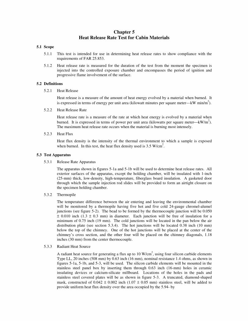
The apparatus shown in figures 5-1a and 5-1b will be used to determine heat release rates. All
exterior surfaces of the apparatus, except the holding chamber, will be insulated with 1-inch
(25-mm) thick, low-density, high-temperature, fiberglass board insulation. A gasketed door
through which the sample injection rod slides will be provided to form an airtight closure on
the specimen holding chamber.
5.3.2 Thermopile
The temperature difference between the air entering and leaving the environmental chamber
will be monitored by a thermopile having five hot and five cold 24-gauge chromel-alumel
junctions (see figure 5-2). The bead to be formed by the thermocouple junction will be 0.050
± 0.010 inch (1.3 ± 0.3 mm) in diameter. Each junction will be free of insulation for a
minimum of 0.75 inch (19 mm). The cold junctions will be located in the pan below the air
distribution plate (see section 5.3.4). The hot junctions will be located 0.38 inch (10 mm)
below the top of the chimney. One of the hot junctions will be placed at the center of the
chimney’s cross section, and the other four will be placed on the chimney diagonals, 1.18
inches (30 mm) from the center thermocouple.
5.3.3 Radiant Heat Source
A radiant heat source for generating a flux up to 10 W/cm2, using four silicon carbide elements
Type LL, 20 inches (508 mm) by 0.63 inch (16 mm), nominal resistance 1.4 ohms, as shown in
figures 5-1a, 5-1b, and 5-3, will be used. The silicon carbide elements will be mounted in the
stainless steel panel box by inserting them through 0.63 inch (16-mm) holes in ceramic
insulating devices or calcium-silicate millboard. Locations of the holes in the pads and
stainless steel covered plates will be as shown in figure 5-3. A truncated, diamond-shaped
mask, constructed of 0.042 ± 0.002 inch (1.07 ± 0.05 mm) stainless steel, will be added to
provide uniform heat flux density over the area occupied by the 5.94- by
Figure 5-1a. Rate of Heat Release Apparatus

Figure 5-1b. Rate of Heat Release Apparatus
Test Chamber
0.049 ±±±±0.002 in
(1.24 ±±±±0.05 mm)
0.140 ±±±±0.001 in
(3.6 ±±±±0.03 mm)
0.39 ±±±±0.02 in
(10 ±±±±0.5 mm)

Figure 5-2. Thermopile
5.94-inch (151- by 151-mm) vertical sample. An adjustable power supply capable of
producing 12.5 kVA will be provided. The heat flux over the specimen surface when set at 3.5
W/cm2 will be uniform within 5 percent and will be checked periodically and after each
heating element change. Uniformity of heat flux density will be determined by heat flux
sensor measurements at the center and at the four corners of the specimen surface.
5.3.4 Air Distribution System
The air entering the apparatus will be 70 to 75°F (21 to 24°C) and set at approximately 85
ft3/min (0.04 m
3/s) using an orifice meter. The orifice meter will be comprised of a squared-
edged, circular plate orifice, 0.024 inch (0.5 mm) thick, located in a circular pipe with a
nominal diameter of 1.5 inches (38 mm), with two pressure measuring points located 1.5
inches (38 mm) upstream (above) and 0.75 inch (19 mm) downstream (below) the orifice and
connected to a mercury manometer. The inlet pipe will remain a nominal diameter of 1.5
inches (38 mm) (see figure 5-la).
5.3.4.1 The air entering the environmental chamber will be distributed by a 0.25-inch (6.3-
mm) -thick aluminum plate having eight 0.209- ± 0.001-inch (5.3- ± 0.03-mm) -
diameter holes, 2 inches (51 mm) from the sides on 4-inch (102-mm) centers,
mounted at the base of the environmental chamber. A second plate having 120
evenly spaced, 0.140- ± 0.001-inch (3.6- ± 0.03-mm) -diameter holes, will be
mounted 6 inches (152 mm) above the aluminum plate (see figure 5-1b).
5.3.4.2 The air supply manifold at the base of the pyramidal section will have 48 evenly
spaced, 0.147- ± 0.001-inch (3.7- ± 0.03-mm) -diameter holes 0.38 inch (10 mm)
from the inner edge of the manifold, resulting in an airflow split of approximately
three to one within the apparatus (see figure 5-1a).
5.3.5 Exhaust Stack
An exhaust stack, 5.25 by 2.75 inches (133 by 70 mm) in cross section and 10 inches (254
mm) long, fabricated from stainless steel, 0.018 ± 0.002 inch (0.46 ± 0.05 mm), will be
mounted on the outlet of the pyramidal section (see figures 5-1a and 5-1b). A 1- by 3-inch
(25- by 76-mm) plate of 0.018- ± 0.002-inch (0.46- ± 0.05-mm) -thick stainless steel will be
centered inside the stack, perpendicular to the airflow, 3 inches (76 mm) above the base of the
stack.

Figure 5-3. Side View—Global Radiant Heat Panel
5.3.6 Specimen Holders
Specimen holders will be fabricated from a stainless steel sheet, 0.018 ± 0.002 inch (0.46 ±
0.05 mm) thick, as shown in figure 5-4. Specimen holders will be attached to the injection rod
using the mounting bracket shown in figure 5-4. Each holder will be provided with a V-
shaped spring pressure plate. The position of the spring pressure plate can be changed to
accommodate different specimen thicknesses by inserting the retaining rod in different holes of
the specimen holder frame. Each holder will also have two wires attached vertically to the
front of the holder to secure the face of the specimen in the holder.
5.3.6.1 Drip Pan
A drip pan will be fabricated from a stainless steel sheet, 0.018 ± 0.002 inch (0.46
± 0.05 mm) thick, as shown in figure 5-4, and be attached to the specimen holder
using the flanges shown in figure 5-4. Drip pans may be needed to prevent melting
specimens from dripping into the lower test section. Foil can be used to line the
drip pan to facilitate cleaning after use.
5.3.7 Heat Flux Sensor
A water-cooled, foil-type Gardon Gauge heat flux sensor will be used to measure the heat flux
density at a point where the center of the specimen surface is located at the start of the test.
When positioned to measure heat flux density, the sensor surface will be flush with the
supporting device surface so that air heated by such a support does not contact the sensor
surface.
0.042 ±±±± 0.002 in
(1.07 ±±±± 0.05 mm) thick
0.030 ±±±± 0.008 in
(0.762 ±±±± 0.200 mm)
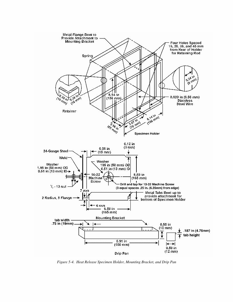
Figure 5-4. Heat Release Specimen Holder, Mounting Bracket, and Drip Pan
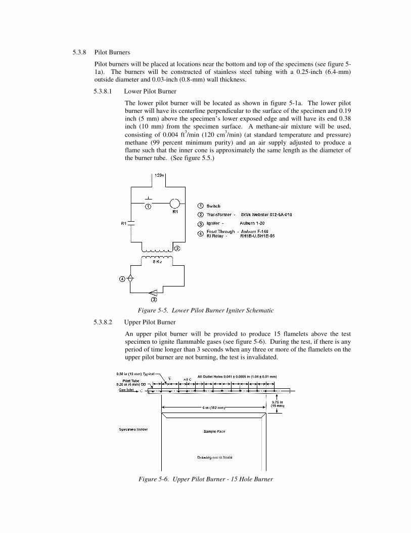
5.3.8 Pilot Burners
Pilot burners will be placed at locations near the bottom and top of the specimens (see figure 5-
1a). The burners will be constructed of stainless steel tubing with a 0.25-inch (6.4-mm)
outside diameter and 0.03-inch (0.8-mm) wall thickness.
5.3.8.1 Lower Pilot Burner
The lower pilot burner will be located as shown in figure 5-1a. The lower pilot
burner will have its centerline perpendicular to the surface of the specimen and 0.19
inch (5 mm) above the specimen’s lower exposed edge and will have its end 0.38
inch (10 mm) from the specimen surface. A methane-air mixture will be used,
consisting of 0.004 ft3/min (120 cm
3/min) (at standard temperature and pressure)
methane (99 percent minimum purity) and an air supply adjusted to produce a
flame such that the inner cone is approximately the same length as the diameter of
the burner tube. (See figure 5.5.)
Figure 5-5. Lower Pilot Burner Igniter Schematic
5.3.8.2 Upper Pilot Burner
An upper pilot burner will be provided to produce 15 flamelets above the test
specimen to ignite flammable gases (see figure 5-6). During the test, if there is any
period of time longer than 3 seconds when any three or more of the flamelets on the
upper pilot burner are not burning, the test is invalidated.
Figure 5-6. Upper Pilot Burner - 15 Hole Burner
All Outlet Holes 0.041 ±±±± 0.0005 in (1.04 ±±±± 0.01 mm)
5.3.8.2.1 The upper pilot burner will be constructed from a piece of stainless
steel tubing with an outside diameter (OD) of 0.25 inch (6.3 mm) and a
wall thickness of 0.03 inch (0.8 mm). Fifteen 0.041 ± 0.0005-inch
(1.04 ± 0.01-mm) -diameter holes, each radiating in the same direction,
will be drilled into a 15-inch (381-mm) length of tubing. The holes
will be spaced 0.5 inch (13 mm) apart with the first hole located 0.5
inch (13 mm) from the closed end, as shown in figure 5-6. The tubing
will be inserted into the environmental chamber through a 0.25-inch
(6.3-mm) hole drilled to locate the tubing 0.79 inch (20 mm) above and
0.79 inch (20 mm) behind the upper front edge of the specimen holder
and installed so that the holes are directed horizontally toward the
radiant heat source. One end of the tubing will be closed with a silver
solder plug or equivalent.
5.3.8.2.2 The burner will be positioned above the specimen holder so that the
holes are placed above the specimen holder facing the heat source, as
shown in figure 5-1a.
5.3.8.2.3 The fuel fed to this burner will be methane of 99 percent minimum
purity mixed with air in a ratio of approximately 50/50 by volume. The
total fuel flow will be adjusted to provide flamelets approximately 1
inch (25 mm) long. When the gas/air ratio and its fuel flow rate are
properly adjusted, approximately 0.25 inch (6 mm) of the flame length
appears yellow in color.
5.4 Test Specimens
5.4.1 Specimen Size
The standard size for specimens is 5.94 + 0, -0.06 by 5.94 + 0, -0.06 inches (150 + 0, -2 by 150
+ 0, -2 mm) in lateral dimensions. Specimen thickness is as used in the relevant application up
to 1.75 inches (45 mm); applications requiring thicknesses greater than 1.75 inches (45 mm)
will be tested in 1.75-inch (45-mm) thicknesses.
5.4.2 Specimen Number
A minimum of three specimens will be prepared and tested for each material/part.
5.4.3 Specimen Mounting
Only one surface of a specimen will be exposed during a test. A single layer of 0.0012 ±
0.0005-inch (0.03 ± 0.01-mm) -thick aluminum foil will be wrapped tightly on all unexposed
sides with the dull side of the foil facing the specimen surface. The foil must be continuous
and not torn. The retaining frame will be placed behind the specimen between the back of the
specimen and the pressure plate.
5.4.4 Specimen Orientation
For materials that may have anisotropic properties (i.e., different properties in different
directions, such as machine and cross-machine directions for extrusions, warp and fill
directions of woven fabrics, etc.), the specimens will be tested in the orientation thought to
give the highest results. If the average maximum heat release rate exceeds 58 kW/m2 or the
average total heat released during the first 2 minutes exceeds 58 kW min/m2, a second set of
specimens will be prepared and tested in the orientation that is perpendicular to the orientation
used for the first set of specimens. The higher value for the average maximum heat release
rate and the higher value for the average total heat released during the first 2 minutes will be
reported.
5.5 Conditioning
5.5.1 Specimens will be conditioned at 70 ± 5°F (21 ± 3°C) and 50% ± 5% relative humidity for a
minimum of 24 hours prior to test.
5.6 Calibration
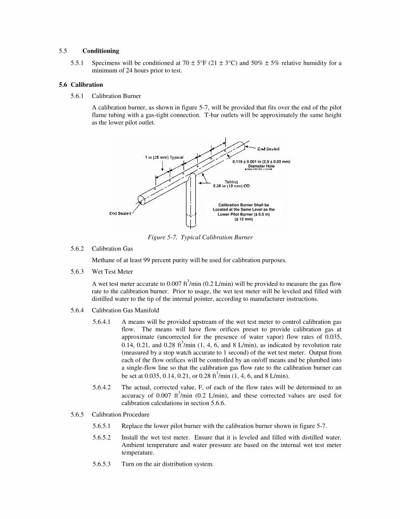
5.6.1 Calibration Burner
A calibration burner, as shown in figure 5-7, will be provided that fits over the end of the pilot
flame tubing with a gas-tight connection. T-bar outlets will be approximately the same height
as the lower pilot outlet.
Figure 5-7. Typical Calibration Burner
5.6.2 Calibration Gas
Methane of at least 99 percent purity will be used for calibration purposes.
5.6.3 Wet Test Meter
A wet test meter accurate to 0.007 ft3/min (0.2 L/min) will be provided to measure the gas flow
rate to the calibration burner. Prior to usage, the wet test meter will be leveled and filled with
distilled water to the tip of the internal pointer, according to manufacturer instructions.
5.6.4 Calibration Gas Manifold
5.6.4.1 A means will be provided upstream of the wet test meter to control calibration gas
flow. The means will have flow orifices preset to provide calibration gas at
approximate (uncorrected for the presence of water vapor) flow rates of 0.035,
0.14, 0.21, and 0.28 ft3/min (1, 4, 6, and 8 L/min), as indicated by revolution rate
(measured by a stop watch accurate to 1 second) of the wet test meter. Output from
each of the flow orifices will be controlled by an on/off means and be plumbed into
a single-flow line so that the calibration gas flow rate to the calibration burner can
be set at 0.035, 0.14, 0.21, or 0.28 ft3/min (1, 4, 6, and 8 L/min).
5.6.4.2 The actual, corrected value, F, of each of the flow rates will be determined to an
accuracy of 0.007 ft3/min (0.2 L/min), and these corrected values are used for
calibration calculations in section 5.6.6.
5.6.5 Calibration Procedure
5.6.5.1 Replace the lower pilot burner with the calibration burner shown in figure 5-7.
5.6.5.2 Install the wet test meter. Ensure that it is leveled and filled with distilled water.
Ambient temperature and water pressure are based on the internal wet test meter
temperature.
5.6.5.3 Turn on the air distribution system.
Calibration Burner Shall be Located at the Same Level as the
Lower Pilot Burner (±±±± 0.5 in)
(±±±± 12 mm)
0.116 ±±±± 0.001 in (2.9 ±±±± 0.03 mm) Diameter Hole
5.6.5.4 Turn on the radiant heat source and ensure that the heat flux is 3.5 ± 0.05 W/cm2.
5.6.5.5 Using the calibration gas manifold, set the baseline flow rate of 1 L/min of methane
to the calibration burner and light the burner. Measure the thermopile baseline
voltage.
5.6.5.6 Immediately prior to recording the thermopile outputs, as discussed in section
5.6.5.7, precondition the chamber at a methane flow rate of 8 L/min for 2 minutes.
Do not record the thermopile output for this step as part of the calibration.
5.6.5.7 The gas flow to the burner is increased to a higher flow rate and then decreased to
the baseline flow rate. After 2 minutes of burning at each rate, monitor the
thermopile output (millivolts) for a 10-second period, record the average reading,
and decrease the flow rate to the baseline flow of 1 L/min. This sequence of
increasing and decreasing the methane flow rate is as follows: 0.035 - 0.14 - 0.035
- 0.21 - 0.035 - 0.28 - 0.035 - 0.21 - 0.035 - 0.14 ft3/min (1 - 4 - 1 - 6 - 1 - 8 - 1 - 6 -
1 - 4 L/min).
5.6.6 Compute the calibration factor for each upward rate step (i.e., 1 - 4, 1 - 6, 1 - 8, 1 - 6, 1 - 4
L/min) according to the following formula:
mvmkWVV
FFPP
Tk va
a
h −−
−×
−××=
2
01
01 /)(
)(
760
)(27331.25
where:
F1 = Actual upper flow rate of calibration gas, in L/min (either 4, 6, or 8)
F0 = Actual baseline flow rate of methane, in L/min (approximately 1 L/min)
Pa = Ambient atmospheric pressure, in mm Hg
Pv = Water vapor pressure of wet test meter water temperature, in mm Hg
Ta = Ambient temperature, in °K
V1 = Thermopile voltage at upper flow rate, in mv
V0 = Thermopile voltage at baseline flow rate, in mv
5.6.7 Average the five results and compute the percent relative standard deviation. If the percent
relative standard deviation is greater than 5 percent, repeat the determination. If it is less than 5
percent, use the average as the calibration factor.
5.7 Test Procedure
5.7.1 Set the airflow to the equipment by adjusting the pressure differential across the orifice plate to
7.87 inches (200 mm) of mercury.
5.7.2 Set the power supply to the Globars to produce a radiant flux density of 3.5 ± 0.05 W/cm2 at
the point that the center of the front surface of the specimen will occupy when positioned for
test.
5.7.3 Light the pilot flames and check that their positions are as described in sections 5.3.8.1 and
5.3.8.2. Activate the spark igniter if a spark igniter is used.
5.7.4 If the test specimen consists of material that sags and/or drips to the extent that part of it may
fall out of the holder during the test, attach the drip pan to the specimen holder, as described in
section 5.3.6.1.
5.7.5 Place the specimen in the hold chamber with the radiation shield doors closed. Secure the
airtight outer door and start the recording devices. Hold the specimen in the hold chamber for
60 ± 10 seconds.

5.7.6 Record, at least once a second, the thermopile millivolt output during the final 20 seconds of
the hold time before the specimen is injected, and report the average as the baseline thermopile
reading (millivolts).
5.7.7 After recording the baseline reading and within a timeframe not exceeding 3 seconds, open the
radiation doors, inject the specimen into the burn chamber, and close the radiation doors.
Record thermopile millivolt outputs at least once a second for the duration of the test.
5.7.8 After the test has run for 5 minutes, terminate the test and remove the sample.
5.7.9 Observe and note any extinguishment of pilot flames then discard data from any test during
which the lower pilot burner was extinguished for any period of time exceeding 3 seconds or
during which at least three of the upper pilot flamelets were extinguished simultaneously for
any period of time exceeding 3 seconds.
5.7.10 Calculate the heat release rate for any point of time from the reading of the thermopile output
voltage, V at that time as heat release rate = kh × (V1 - V0), where kh and V0 are the calibration
factor and thermopile millivolt reading at the baseline, respectively.
5.7.11 Determine and record the maximum heat release rate during the 5-minute test.
5.7.12 Compute and record the total heat released during the first 2 minutes of testing by integrating
the heat release rate versus time curve during the first 2 minutes.
5.7.13 Clean the thermopile hot junctions to remove soot after testing each set of specimens.
5.8 Report
5.8.1 Fully identify the material tested, including thickness.
5.8.2 Determine and record the average maximum heat release rate during the 5-minute test, and the
average total heat released during the first 2 minutes for all specimens tested (in worst-case
direction).
5.8.3 Report the radiant heat flux to the specimen in W/cm2 and data giving release rates of heat (in
kW/m2) as a function of time, either graphically or tabulated at intervals no greater than 10
seconds, and the calibration factor kh.
5.8.4 Report any melting, sagging, delamination, or other behavior that affected the exposed surface
area or mode of burning that occurred and the time(s) at which such behavior occurred.
5.9 Requirements
5.9.1 The average maximum heat release rate during the 5-minute tests will not exceed 65 kW/m2.
5.9.2 The average total heat released during the first 2 minutes will not exceed 65 kW min/m2.
NOTE: The 65/65 acceptance criteria above are the definitive requirements in FAR 25, Amendment
25-61 (FAR 25.853[a-1]), covering affected new design airplanes whose Type Certificate is
applied for after August 20, 1986. These definitive requirements are referenced in FAR 121,
Amendment 121-189, and are required for all affected airplanes manufactured after August
20, 1990. All affected airplanes manufactured after August 20, 1988, but prior to August 20,
1990, must meet interim requirements of 100 kW/m2 for the average heat release rate and 100
kW min/m2 for the average total heat released during the first 2 minutes.

Chapter 5 Supplement
This supplement contains advisory material pertinent to referenced paragraphs.
5.3.2 The upper thermocouples in the thermopile must remain in the same position as when the last
calibration was completed. A template may be necessary to maintain this position. Caution must be taken
while cleaning the thermocouple junctions not to move them.
5.3.3 A device should be provided to monitor the current of the heating elements (globars) during
testing; additionally, this may be used to adjust the globar current during initial warm up, before final
adjustment.
5.3.4 The air distribution system circular plate orifice should be no thicker than 0.125 inch. The inner
edges of the holes must be sharp. The holes in the lower plate are #4 drill size. The holes in the upper
manifold are #26 drill size. The holes in the intermediate plate used for air flow disbursement are #28 drill
size.
5.3.5 The exhaust stack and area above the upper manifold should be cleaned periodically of soot
deposits.
5.3.7 A second calorimeter should be used periodically to check the active calorimeter and its
calibration should be first generation from National Institute of Standards and Technology (NIST) or the
calorimeter manufacturer.
5.3.8 A method to provide reignition of the lower pilot flame is recommended. A spark ignitor should
be installed to ensure that the lower pilot burner remains burning. A test is invalidated if the lower pilot
burner becomes extinguished for any period that exceeds 3 seconds. A circuit for a satisfactory device is
sketched in figure 5-5.
If an electric sparking device is used, an appropriate method of suppression and equipment shielding must
be applied to have no interference with the ability of the data acquisition equipment to accurately record
data.
5.3.8.2 The upper pilot holes are #59 drill size.
5.4.1 to be added: reducing thickness of sample
5.4.2 For test purposes, specimens should be marked with an arrow by manufacturers or operators for a
consistent direction.
5.4.4 If there is evidence that a material does not demonstrate isotropic flammability characteristics and
its heat release numbers in any one direction average greater than 58, either 2 minute or peak, the material
must be tested in both directions. Examples of those types of materials that may not exhibit isotropic
flammability characteristics are rugs and textiles.
5.6.1 The calibration T-bar burner holes are #32 drill size.
5.6.3 The tubing from the wet test meter to the calibration T-bar must be as short as possible and direct
in routing. Also, the wet test meter must be last in line to the calibration T-bar.
5.7.6 Extreme caution must be used to ensure that the baseline reading is completed prior to opening
inner doors for sample injection.
5.7.9 The use of an externally positioned mirror may assist in viewing upper pilot flames during testing.

5.7.13 A small, soft-bristled brush has been found satisfactory. Do not disturb the position of the
thermocouples. Ensure that the thermocouples are in their proper position before proceeding with the next
specimen; a template may be used to facilitate this step.


![Heat Shock Protein HSP101 Affects the Release of … · Heat Shock Protein HSP101 Affects the Release of Ribosomal Protein mRNAs for Recovery after Heat Shock1[OPEN] Rémy Merret2*,](https://img.pdfslide.us/doc/110x75/5bbb60e709d3f241268cd182/heat-shock-protein-hsp101-affects-the-release-of-heat-shock-protein-hsp101-affects.jpg)