Embed Size (px)
Citation preview
75
CHAPTER 5
DIGITAL DISTANCE RELAYING SCHEME FOR SERIES
COMPENSATED PARALLEL LINES DURING SIMULTANEOUS
OPEN CONDUCTOR & GROUND FAULT
5.1 INTRODUCTION
The main purpose of using series compensated transmission lines is to cancel out a
portion of the inductive reactance of the transmission line; thereby improving the power
transmission capability of the transmission line. There are several other reasons for favouring
the use of series compensated long EHV/UHV transmission lines. The benefits include:
increased transmittable power, improved system stability, reduced transmission losses,
enhanced voltage control, more flexible power flow control and cost benefits are the technical
reasons favouring the application of series compensated transmission lines.
For these reasons, the use of series compensated transmission lines has increased for
EHV/UHV transmission lines carrying huge amount of power for a long distance. Series
compensation is usually stated in terms of a percentage of the transmission line inductive
reactance, which is referred to as the “degree of compensation”. Typically, the series
capacitors are used to compensate for 25% to 75% of the inductive reactance of the
transmission line; it means that the degree of series compensation is 25% to 75%. Normally,
the series capacitors are located at the ends of the transmission lines as it is the least
expensive alternative, since no middle station is required. However, this alternative may
cause a distance relay to measure a negative reactance for a close-in fault.
The series capacitors essentially violate a fundamental principle upon which distance
protection is built; that is the apparent impedance varies proportionally with the distance to
the fault. The series capacitors are exposed to a wide range of currents, which can result in
the development of large voltages across the capacitors. Generally, it is uneconomical to
design the capacitors to withstand these over-voltages, thus additional equipment, namely
metal oxide varistor (MOV) is usually provided to protect the series capacitors. Obviously,
the non-linear characteristic of this MOV is of concern to the protection engineers. Because,
the majority of distance relays respond to more (security) or less (speed) accurately filtered
fundamental frequency components. Therefore, it becomes necessary to understand relations
76
between the fundamental frequency voltage and current of a typical arrangement of series
capacitors and their overvoltage protection devices.
5.2 SERIES CAPACITORS: THEORY AND OPERATION
5.2.1 Aim of Series Compensation
The main objective of providing series compensation to the EHV/UHV transmission
lines is to reduce the inductive reactance of the transmission line by the addition of series
capacitors. Further, it increases the line loading capacity and stability margins of the power
system. This is apparent by reviewing the basic equation of power transfer between two buses
by the series compensated transmission line, and it is given by [76],
CL XXEEP
sin21 (5.1)
Where, P is the amount of power transfer by the series compensated transmission line,
is the angle between the E1 and E2 voltages, XL is the inductive reactance of the
transmission line and XC is the capacitive reactance of the series capacitor. It is to be noted
from equation (5.1) that XC reduces the total transfer impedance thus allowing increased
power flow for the same system angle; or a reduction in the power transfer angle for the
same power transfer level, thus increasing the stability margins [76].
5.2.2 Series Compensated Transmission Line
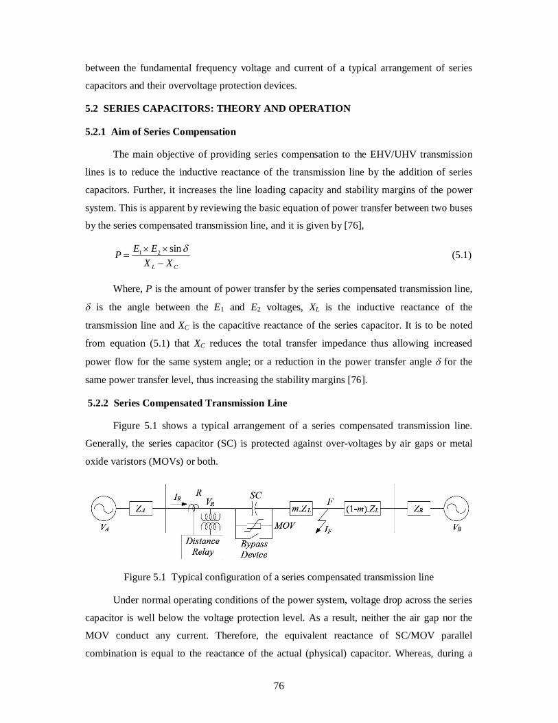
Figure 5.1 shows a typical arrangement of a series compensated transmission line.
Generally, the series capacitor (SC) is protected against over-voltages by air gaps or metal
oxide varistors (MOVs) or both.
Figure 5.1 Typical configuration of a series compensated transmission line
Under normal operating conditions of the power system, voltage drop across the series
capacitor is well below the voltage protection level. As a result, neither the air gap nor the
MOV conduct any current. Therefore, the equivalent reactance of SC/MOV parallel
combination is equal to the reactance of the actual (physical) capacitor. Whereas, during a
77
fault and depending on the fault current magnitude, both SC and MOV will conduct a portion
of the fault current; thereby modifying the impedance of the capacitor bank.
5.2.3 Series Capacitor Bypass Systems
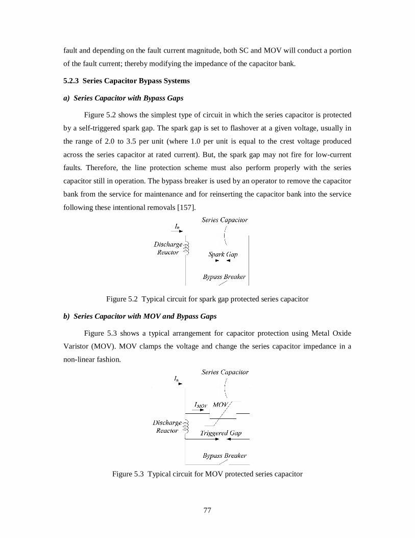
a) Series Capacitor with Bypass Gaps
Figure 5.2 shows the simplest type of circuit in which the series capacitor is protected
by a self-triggered spark gap. The spark gap is set to flashover at a given voltage, usually in
the range of 2.0 to 3.5 per unit (where 1.0 per unit is equal to the crest voltage produced
across the series capacitor at rated current). But, the spark gap may not fire for low-current
faults. Therefore, the line protection scheme must also perform properly with the series
capacitor still in operation. The bypass breaker is used by an operator to remove the capacitor
bank from the service for maintenance and for reinserting the capacitor bank into the service
following these intentional removals [157].
Figure 5.2 Typical circuit for spark gap protected series capacitor
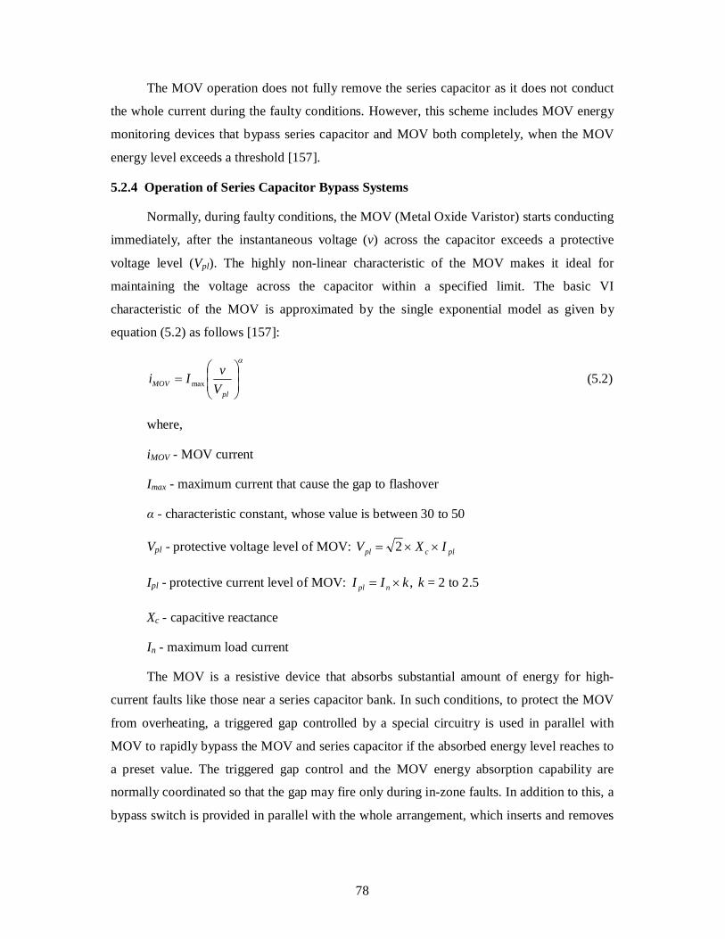
b) Series Capacitor with MOV and Bypass Gaps
Figure 5.3 shows a typical arrangement for capacitor protection using Metal Oxide
Varistor (MOV). MOV clamps the voltage and change the series capacitor impedance in a
non-linear fashion.
Figure 5.3 Typical circuit for MOV protected series capacitor
78
The MOV operation does not fully remove the series capacitor as it does not conduct
the whole current during the faulty conditions. However, this scheme includes MOV energy
monitoring devices that bypass series capacitor and MOV both completely, when the MOV
energy level exceeds a threshold [157].
5.2.4 Operation of Series Capacitor Bypass Systems
Normally, during faulty conditions, the MOV (Metal Oxide Varistor) starts conducting
immediately, after the instantaneous voltage (v) across the capacitor exceeds a protective
voltage level (Vpl). The highly non-linear characteristic of the MOV makes it ideal for
maintaining the voltage across the capacitor within a specified limit. The basic VI
characteristic of the MOV is approximated by the single exponential model as given by
equation (5.2) as follows [157]:
plMOV V
vIi max (5.2)
where,
iMOV - MOV current
Imax - maximum current that cause the gap to flashover
α - characteristic constant, whose value is between 30 to 50
Vpl - protective voltage level of MOV: plcpl IXV 2
Ipl - protective current level of MOV: ,kII npl k = 2 to 2.5
Xc - capacitive reactance
In - maximum load current
The MOV is a resistive device that absorbs substantial amount of energy for high-
current faults like those near a series capacitor bank. In such conditions, to protect the MOV
from overheating, a triggered gap controlled by a special circuitry is used in parallel with
MOV to rapidly bypass the MOV and series capacitor if the absorbed energy level reaches to
a preset value. The triggered gap control and the MOV energy absorption capability are
normally coordinated so that the gap may fire only during in-zone faults. In addition to this, a
bypass switch is provided in parallel with the whole arrangement, which inserts and removes
79
the capacitor bank from the service and also provides protection to the complete assembly for
failures or imbalances.
The MOV protection is designed to hold the capacitor voltage at or below the peak
value even for the highest fault currents. It has been observed from the results of field tests
and simulations involving MOV-protected series capacitors that even though the capacitor is
paralleled by a highly nonlinear device, the resulting total current through the SC/MOV
combination remains remarkably sinusoidal. This effect can be attributed to the system
inductance which is the major component in determining the fault current.
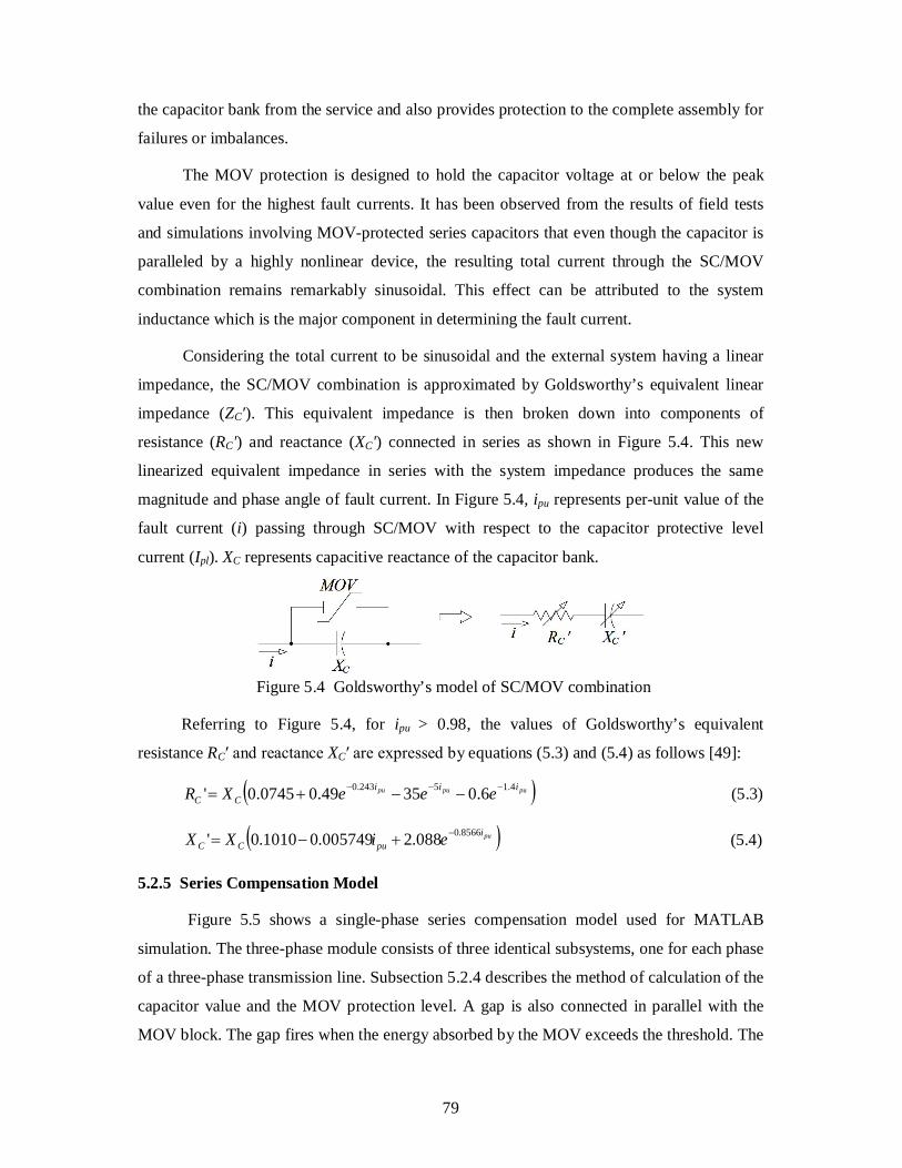
Considering the total current to be sinusoidal and the external system having a linear
impedance, the SC/MOV combination is approximated by Goldsworthy’s equivalent linear
impedance (ZC'). This equivalent impedance is then broken down into components of
resistance (RC') and reactance (XC') connected in series as shown in Figure 5.4. This new
linearized equivalent impedance in series with the system impedance produces the same
magnitude and phase angle of fault current. In Figure 5.4, ipu represents per-unit value of the
fault current (i) passing through SC/MOV with respect to the capacitor protective level
current (Ipl). XC represents capacitive reactance of the capacitor bank.
Figure 5.4 Goldsworthy’s model of SC/MOV combination
Referring to Figure 5.4, for ipu > 0.98, the values of Goldsworthy’s equivalent
resistance RC′ and reactance XC′ are expressed by equations (5.3) and (5.4) as follows [49]:
pupupu iiiCC eeeXR 4.15243.0 6.03549.00745.0' (5.3)
puipuCC eiXX 8566.0088.2005749.01010.0' (5.4)
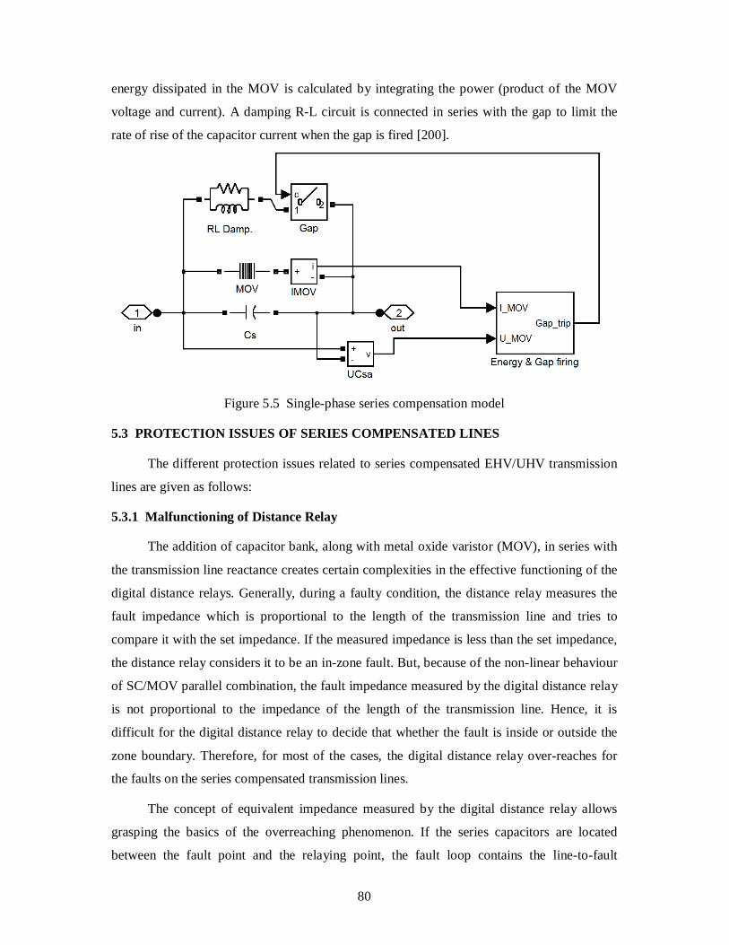
5.2.5 Series Compensation Model
Figure 5.5 shows a single-phase series compensation model used for MATLAB
simulation. The three-phase module consists of three identical subsystems, one for each phase
of a three-phase transmission line. Subsection 5.2.4 describes the method of calculation of the
capacitor value and the MOV protection level. A gap is also connected in parallel with the
MOV block. The gap fires when the energy absorbed by the MOV exceeds the threshold. The
80
energy dissipated in the MOV is calculated by integrating the power (product of the MOV
voltage and current). A damping R-L circuit is connected in series with the gap to limit the
rate of rise of the capacitor current when the gap is fired [200].
Figure 5.5 Single-phase series compensation model
5.3 PROTECTION ISSUES OF SERIES COMPENSATED LINES
The different protection issues related to series compensated EHV/UHV transmission
lines are given as follows:
5.3.1 Malfunctioning of Distance Relay
The addition of capacitor bank, along with metal oxide varistor (MOV), in series with
the transmission line reactance creates certain complexities in the effective functioning of the
digital distance relays. Generally, during a faulty condition, the distance relay measures the
fault impedance which is proportional to the length of the transmission line and tries to
compare it with the set impedance. If the measured impedance is less than the set impedance,
the distance relay considers it to be an in-zone fault. But, because of the non-linear behaviour
of SC/MOV parallel combination, the fault impedance measured by the digital distance relay
is not proportional to the impedance of the length of the transmission line. Hence, it is
difficult for the digital distance relay to decide that whether the fault is inside or outside the
zone boundary. Therefore, for most of the cases, the digital distance relay over-reaches for
the faults on the series compensated transmission lines.
The concept of equivalent impedance measured by the digital distance relay allows
grasping the basics of the overreaching phenomenon. If the series capacitors are located
between the fault point and the relaying point, the fault loop contains the line-to-fault
81
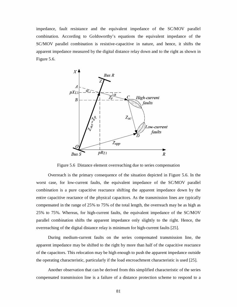
impedance, fault resistance and the equivalent impedance of the SC/MOV parallel
combination. According to Goldsworthy’s equations the equivalent impedance of the
SC/MOV parallel combination is resistive-capacitive in nature, and hence, it shifts the
apparent impedance measured by the digital distance relay down and to the right as shown in
Figure 5.6.
Figure 5.6 Distance element overreaching due to series compensation
Overreach is the primary consequence of the situation depicted in Figure 5.6. In the
worst case, for low-current faults, the equivalent impedance of the SC/MOV parallel
combination is a pure capacitive reactance shifting the apparent impedance down by the
entire capacitive reactance of the physical capacitors. As the transmission lines are typically
compensated in the range of 25% to 75% of the total length, the overreach may be as high as
25% to 75%. Whereas, for high-current faults, the equivalent impedance of the SC/MOV
parallel combination shifts the apparent impedance only slightly to the right. Hence, the
overreaching of the digital distance relay is minimum for high-current faults [25].
During medium-current faults on the series compensated transmission line, the
apparent impedance may be shifted to the right by more than half of the capacitive reactance
of the capacitors. This relocation may be high enough to push the apparent impedance outside
the operating characteristic, particularly if the load encroachment characteristic is used [25].
Another observation that can be derived from this simplified characteristic of the series
compensated transmission line is a failure of a distance protection scheme to respond to a
82
low-current close-in fault. During a low-current close-in fault, the apparent impedance moves
to the fourth quadrant of the impedance plane resulting in problems with directional
discrimination [25].
5.3.2 Sub-synchronous Resonance
The series combination of the capacitive reactance of the series capacitors and the
inductive reactance of the system sets up a series resonant circuit, the natural frequency nf
of which can be calculated by [76],
L
Cn X
XfLC
f 2
1
(5.5)
In which, f is the system frequency, XC is the capacitive reactance of the series
capacitor and XL is the total system inductive reactance. Since, XC/XL is typically in the range
of 0.25 to 0.75, fn will be a sub-harmonic of the power frequency.
Any system disturbance produced due to occurrence of a fault, insertion/removal of the
capacitor bank, switching of any series element, etc. will result in the excitation of the system
at the sub-harmonic frequency, which, in turn, can give rise to transient currents. These
transients are typically damped out after a few cycles, but in certain cases, it may last for a
significantly longer duration [76].
The presence of such transients may also excite one or more of the natural torsional
frequencies of the mechanical shaft system of the generators. This complex phenomenon is
known as sub-synchronous resonance (SSR). Depending upon the degree of damping and
resonance, the torsional oscillations may be severe enough to cause damage to the shaft of the
generators and failure of the capacitor bank [76].
5.3.3 Voltage Inversion
Voltage inversion will occur for a close-in fault after a capacitor bank, during which,
the net fault impedance measured at the relaying point is capacitive rather than inductive. As
a result, the voltage applied to the digital distance relay will be shifted approximately by 180º
from its normal position. It means that voltage inversion causes the relay to see a fault on the
protected line to be in a reverse direction. Since, the conventional digital distance relays are
designed to work properly only on inductive system, the voltage inversion will have a
negative effect on the performance of the protective relaying [76].
83
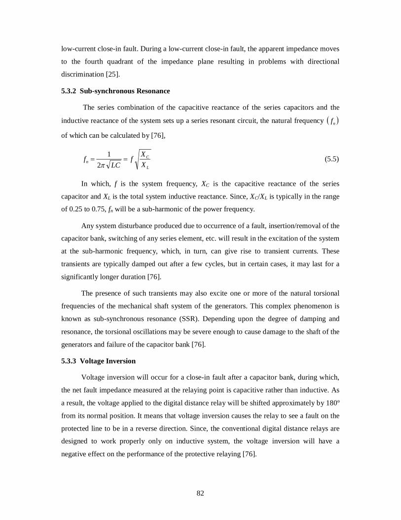
Consider a system shown in Figure 5.7 in which, a digital distance relay is located at
Station A before the capacitor XC and it is looking towards Station B. A three-phase fault F1 is
assumed to be present at fault location F1 near Station A. Therefore, the voltage applied to the
potential coil of a digital distance relay will be the drop across the capacitor. Consequently, it
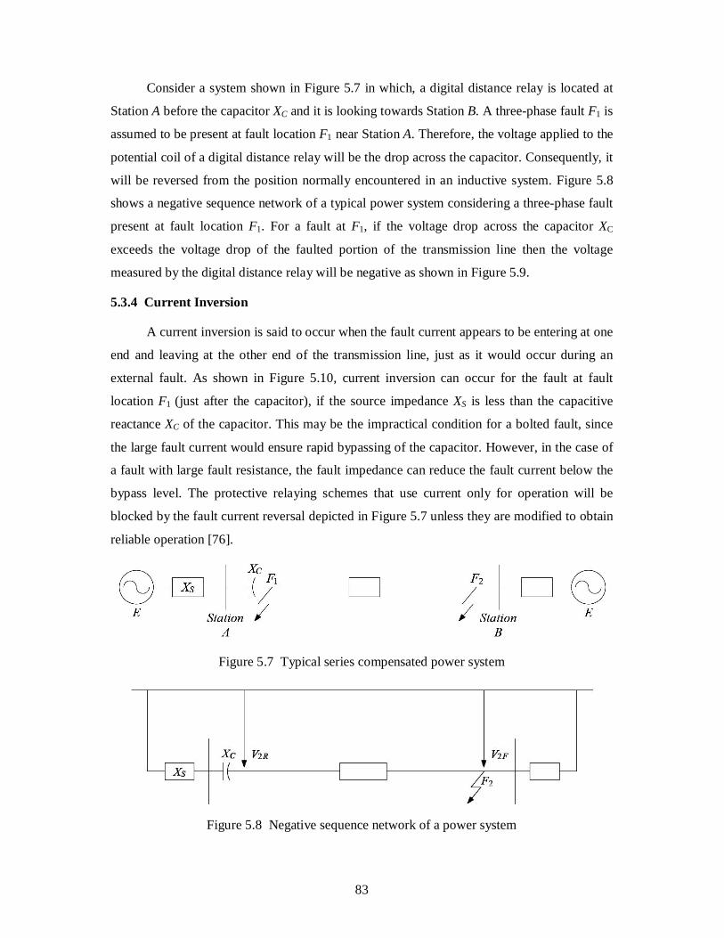
will be reversed from the position normally encountered in an inductive system. Figure 5.8
shows a negative sequence network of a typical power system considering a three-phase fault
present at fault location F1. For a fault at F1, if the voltage drop across the capacitor XC
exceeds the voltage drop of the faulted portion of the transmission line then the voltage
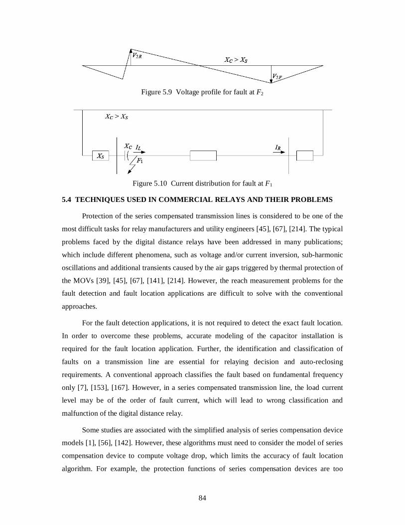
measured by the digital distance relay will be negative as shown in Figure 5.9.
5.3.4 Current Inversion
A current inversion is said to occur when the fault current appears to be entering at one
end and leaving at the other end of the transmission line, just as it would occur during an
external fault. As shown in Figure 5.10, current inversion can occur for the fault at fault
location F1 (just after the capacitor), if the source impedance XS is less than the capacitive
reactance XC of the capacitor. This may be the impractical condition for a bolted fault, since
the large fault current would ensure rapid bypassing of the capacitor. However, in the case of
a fault with large fault resistance, the fault impedance can reduce the fault current below the
bypass level. The protective relaying schemes that use current only for operation will be
blocked by the fault current reversal depicted in Figure 5.7 unless they are modified to obtain
reliable operation [76].
Figure 5.7 Typical series compensated power system
Figure 5.8 Negative sequence network of a power system
84
Figure 5.9 Voltage profile for fault at F2
Figure 5.10 Current distribution for fault at F1
5.4 TECHNIQUES USED IN COMMERCIAL RELAYS AND THEIR PROBLEMS
Protection of the series compensated transmission lines is considered to be one of the
most difficult tasks for relay manufacturers and utility engineers [45], [67], [214]. The typical
problems faced by the digital distance relays have been addressed in many publications;
which include different phenomena, such as voltage and/or current inversion, sub-harmonic
oscillations and additional transients caused by the air gaps triggered by thermal protection of
the MOVs [39], [45], [67], [141], [214]. However, the reach measurement problems for the
fault detection and fault location applications are difficult to solve with the conventional
approaches.
For the fault detection applications, it is not required to detect the exact fault location.
In order to overcome these problems, accurate modeling of the capacitor installation is
required for the fault location application. Further, the identification and classification of
faults on a transmission line are essential for relaying decision and auto-reclosing
requirements. A conventional approach classifies the fault based on fundamental frequency
only [7], [153], [167]. However, in a series compensated transmission line, the load current
level may be of the order of fault current, which will lead to wrong classification and
malfunction of the digital distance relay.
Some studies are associated with the simplified analysis of series compensation device
models [1], [56], [142]. However, these algorithms must need to consider the model of series
compensation device to compute voltage drop, which limits the accuracy of fault location
algorithm. For example, the protection functions of series compensation devices are too
85
simplified in [56], [142]; while the analysis given in [1] ignores the switching among
different operation modes that initiates from the protection function. Thus, those algorithms
inevitably suffer from the errors produced due to inaccuracy of the adopted models.
To overcome the above problems, various protective schemes utilizing traveling wave
principles have been suggested. The high frequency components in the fault waveform
present undesirable effects for most of the fault location algorithms [14], [29]. A fault
detection/fault location algorithm derived from traveling wave principles can handle the
problems of high frequency transients. Fault location methods based on traveling waves are
independent of network configurations and installations. Thus, these methods are suitable for
the series compensated transmission line [96]. However, identifying the desired high
frequency signal becomes problematic. Additionally, the need for a high sampling rate for
identifying the signal also limits the application of the traveling wave based method.
The synchronized PMU-based fault detector/locator technique has been proven
effective for the relaying of transmission line without series compensation device [94], [95],
[135]. However, when the series compensation device is installed in the transmission line,
this technique must be incorporated with the series compensation device model to estimate
voltage drop of the series compensation device in fault location computation.
5.5 CURRENT STATE-OF-THE-ART
For series compensated transmission lines, the problems faced by the distance relay
and some of the solutions to these problems are published in [25], [43], [45], [49], [55], [67],
[184]. The reach settings for the different zones of protection with respect to some of the
typical problems and adaptive approach have been discussed in [13], [22], [88], [136], [154],
[163], [166], [193], [225], [231].
Many researchers have proposed a number of fault location methods for the
transmission lines with series compensation devices [1], [11], [42], [56], [64], [108], [142],
[215], [218]. Most of them have used impedance-based approach [1], [42], [108], [142].
Differential equation based algorithms are introduced in [64]. Wavelet Transform is also
effectively used for fault recognition of series compensated transmission lines [11]. In [56],
[218], application of artificial neural networks combined with the impedance-based approach
to fault location has been presented. Consequently, the use of artificial neural networks
combined with discrete wavelet transform for fault location on thyristor controlled series
compensated lines has also been considered [215]. In turn, [182] presents the usage of
86
wavelet packet for digital protection of series compensated transmission line. However, these
algorithms use direct or indirect measurement of impendence to locate the fault, which would
fail in case of series compensated transmission line due to the non-linear operation of the
capacitor bank.
Spoor and his colleagues [48] suggested the use of carrier aided permissive over-reach
transfer tripping scheme or a carrier blocking scheme to detect inter-circuit faults. However,
this scheme requires communication channel, which increases cost and reduces reliability in
case of failure of link. Agrasar and his co-workers [123] discussed the effect of inter-circuit
faults on the conventional distance relay for parallel transmission lines. However, they have
not considered the effect of simultaneous open conductor and ground fault on series
compensated parallel transmission lines. Saha and his co-workers [141] proposed an
algorithm to protect series compensated transmission lines against various types of phase and
ground faults. But, they have not considered the impact of simultaneous faults. Further, they
have not analyzed the effect of zero-sequence mutual impedance and fault resistance.
Afterwards, Evrenosoglu et al. [44] presented different options for traveling wave
method for locating faults on teed circuits with mutually coupled lines and series capacitors.
Use of traveling wave based fault location algorithms is expanding. They are insensitive to
the fault resistance, power flow and source impedance. In addition, they are more accurate
compared to impedance based methods [3]. However, conventional traveling wave methods
are sensitive to the fault inception angle, noises and faults occurred on the other lines [122],
[207].
Relay design progressing is concerned with the improvement of conventional relay
algorithms based on phasor concepts. The complexities discussed in the protection
performance of the series compensated transmission lines calls for the early fault detection
and high-speed distance relays with good accuracy. One can find some of the advanced
techniques with respect to the early fault detection and phasor estimation proposed in [16],
[64], [141]. Adaptive reach settings of the distance relays for faults involving high arc
resistance have been presented in [37], [108], [155]. Methods for on-line corrections of the
trip boundaries are presented using the wavelet transform in [179], [182], [227] and method
for the development of integrated protection systems is presented in [228].
The conventional digital distance relay system is not able to detect and trip High
impedance faults (HIFs) occurred on series compensated lines. The failure of HIF detection
may lead to potential hazards to human beings and fires [192]. HIFs on the electrical
87
transmission and distribution networks involve arcing and/or nonlinear characteristics of the
fault impedance. Therefore, the main objective of most of the fault detection schemes is to
evaluate the special features in patterns of the voltages and currents in HIFs. In recent years,
several researchers have presented many techniques to detect the HIFs more effectively.
These techniques include discrete wavelet transform with other different methods [17], [148],
[192], down-conductor fault detection via a voltage based method [117] and development of
a fuzzy inference system based on genetic algorithm [143].
Recently, the application of series compensated transmission lines has increased to
transmit bulk power for a long distance. Therefore, it is worth to undertake an effort to
simulate the transient conditions for series compensated transmission line applications, to
fine-tune & verify settings and finally to test the relaying system using digital simulators.
5.6 SIMULTANEOUS OPEN CONDUCTOR AND GROUND FAULT ON SERIES
COMPENSATED PARALLEL TRANSMISSION LINES
5.6.1 Simultaneous Open Conductor and Ground Fault
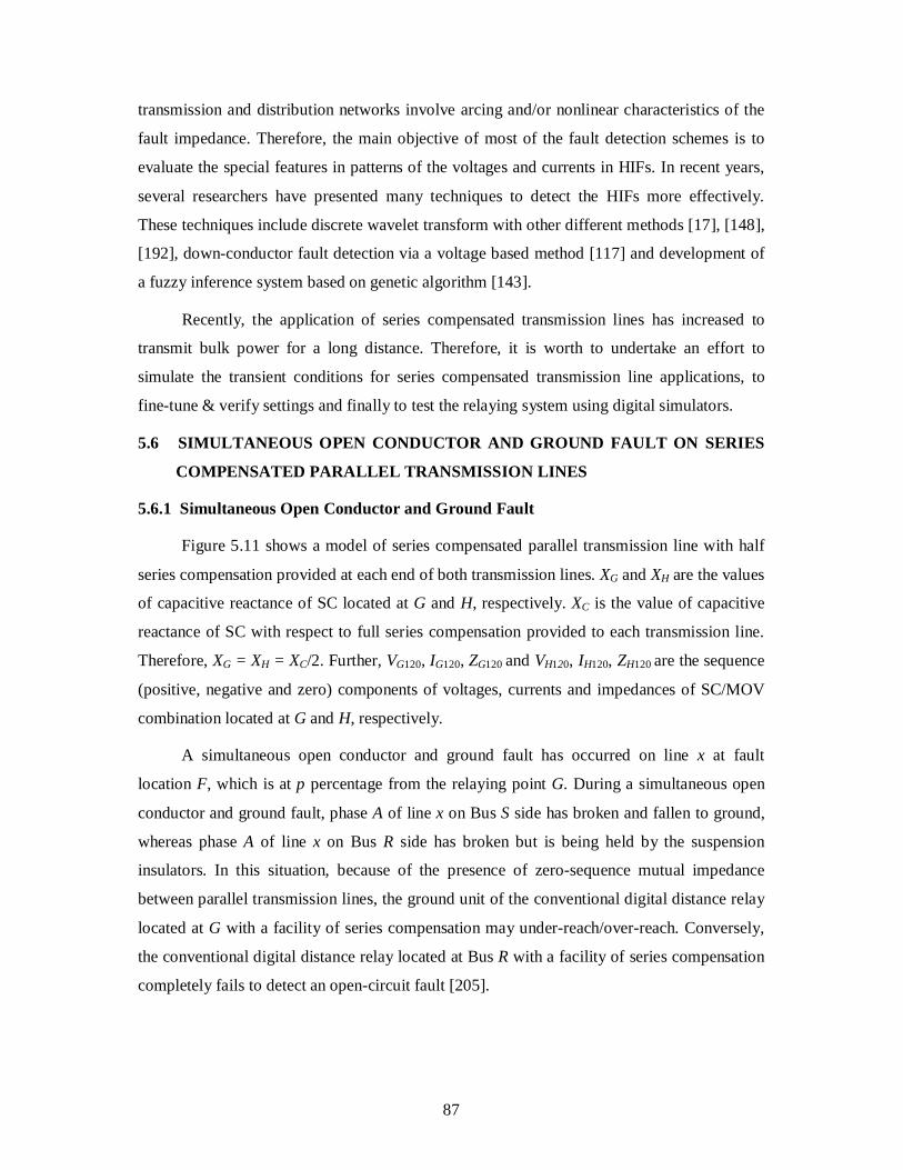
Figure 5.11 shows a model of series compensated parallel transmission line with half
series compensation provided at each end of both transmission lines. XG and XH are the values
of capacitive reactance of SC located at G and H, respectively. XC is the value of capacitive
reactance of SC with respect to full series compensation provided to each transmission line.
Therefore, XG = XH = XC/2. Further, VG120, IG120, ZG120 and VH120, IH120, ZH120 are the sequence
(positive, negative and zero) components of voltages, currents and impedances of SC/MOV
combination located at G and H, respectively.
A simultaneous open conductor and ground fault has occurred on line x at fault
location F, which is at p percentage from the relaying point G. During a simultaneous open
conductor and ground fault, phase A of line x on Bus S side has broken and fallen to ground,
whereas phase A of line x on Bus R side has broken but is being held by the suspension
insulators. In this situation, because of the presence of zero-sequence mutual impedance
between parallel transmission lines, the ground unit of the conventional digital distance relay
located at G with a facility of series compensation may under-reach/over-reach. Conversely,
the conventional digital distance relay located at Bus R with a facility of series compensation
completely fails to detect an open-circuit fault [205].
88
Figure 5.11 Model of a simultaneous open conductor and ground fault
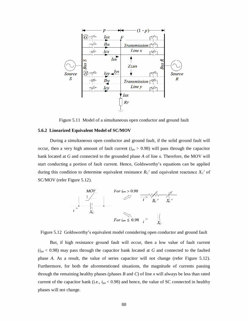
5.6.2 Linearized Equivalent Model of SC/MOV
During a simultaneous open conductor and ground fault, if the solid ground fault will
occur, then a very high amount of fault current (ipu > 0.98) will pass through the capacitor
bank located at G and connected to the grounded phase A of line x. Therefore, the MOV will
start conducting a portion of fault current. Hence, Goldsworthy’s equations can be applied
during this condition to determine equivalent resistance RC′ and equivalent reactance XC′ of
SC/MOV (refer Figure 5.12).
Figure 5.12 Goldsworthy’s equivalent model considering open conductor and ground fault
But, if high resistance ground fault will occur, then a low value of fault current
(ipu < 0.98) may pass through the capacitor bank located at G and connected to the faulted
phase A. As a result, the value of series capacitor will not change (refer Figure 5.12).
Furthermore, for both the aforementioned situations, the magnitude of currents passing
through the remaining healthy phases (phases B and C) of line x will always be less than rated
current of the capacitor bank (i.e., ipu < 0.98) and hence, the value of SC connected in healthy
phases will not change.
89
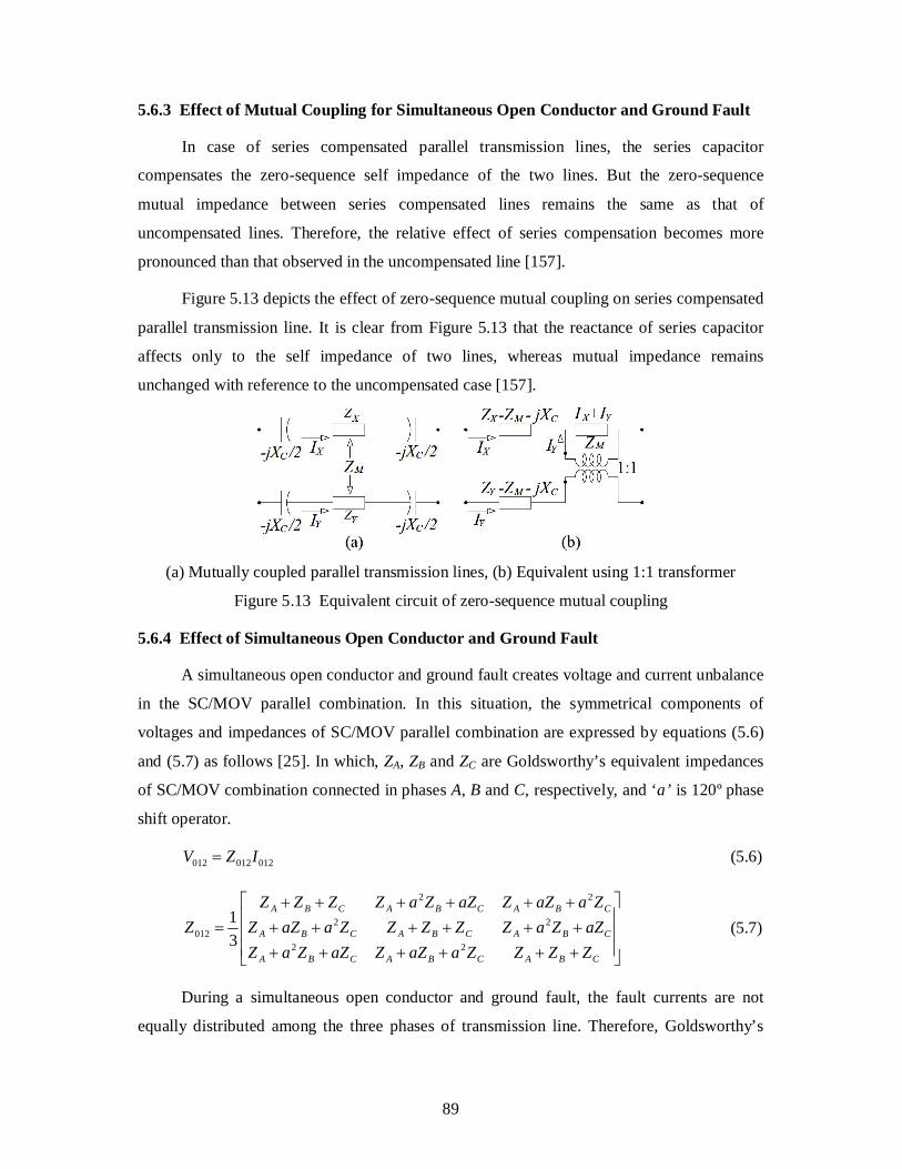
5.6.3 Effect of Mutual Coupling for Simultaneous Open Conductor and Ground Fault
In case of series compensated parallel transmission lines, the series capacitor
compensates the zero-sequence self impedance of the two lines. But the zero-sequence
mutual impedance between series compensated lines remains the same as that of
uncompensated lines. Therefore, the relative effect of series compensation becomes more
pronounced than that observed in the uncompensated line [157].
Figure 5.13 depicts the effect of zero-sequence mutual coupling on series compensated
parallel transmission line. It is clear from Figure 5.13 that the reactance of series capacitor
affects only to the self impedance of two lines, whereas mutual impedance remains
unchanged with reference to the uncompensated case [157].
(a) Mutually coupled parallel transmission lines, (b) Equivalent using 1:1 transformer
Figure 5.13 Equivalent circuit of zero-sequence mutual coupling
5.6.4 Effect of Simultaneous Open Conductor and Ground Fault
A simultaneous open conductor and ground fault creates voltage and current unbalance
in the SC/MOV parallel combination. In this situation, the symmetrical components of
voltages and impedances of SC/MOV parallel combination are expressed by equations (5.6)
and (5.7) as follows [25]. In which, ZA, ZB and ZC are Goldsworthy’s equivalent impedances
of SC/MOV combination connected in phases A, B and C, respectively, and ‘a’ is 120º phase
shift operator.
012012012 IZV (5.6)
CBACBACBA
CBACBACBA
CBACBACBA
ZZZZaaZZaZZaZaZZaZZZZZaaZZZaaZZaZZaZZZZ
Z22
22
22
012 31 (5.7)
During a simultaneous open conductor and ground fault, the fault currents are not
equally distributed among the three phases of transmission line. Therefore, Goldsworthy’s
90
equivalent impedances of SC/MOV connected in the three phases are not equal, as they
depend on the values of fault current [49].
5.7 ANALYSIS OF SIMULTANEOUS OPEN CONDUCTOR AND GROUND FAULT
For all the analysis, positive- and negative-sequence impedances (ZL1 and ZL2) of
parallel transmission lines are assumed to be equal. ZLM0 is the zero-sequence mutual coupling
impedance present between the two lines. Eax and Iax are the voltage and current of phase A of
line x measured at the relaying point G, respectively. Further, Ex120, Ix120 and Ey120, Iy120 are the
sequence (positive, negative and zero) components of voltages and currents of lines x and y
measured at the relaying points G and H, respectively. In all the equations throughout the
entire discussion, subscripts 1, 2 and 0 represent positive-, negative- and zero-sequence
components, respectively.
It is to be noted that during a simultaneous open conductor and ground fault, Bus S
side conductor has been assumed to be broken and fallen to the ground. Since a ground path
is involved in this situation, the fault resistance (RF) plays a key role in the measurement of
apparent impedance. Hence, different values of RF (25, 50, 100 and 150 ) have been
considered in the fault analysis. The ground units of the conventional digital distance relay
located at G, having facility of series compensation, measures incorrect value of impedance
of the faulted portion of the transmission line.
Further, during a simultaneous open conductor and ground fault, the other end of the
conductor (Bus R side) has been assumed to be hanged on the tower without touching to the
ground. The conventional phase and ground distance relays located at Bus R completely fail
to detect this open conductor fault. To solve this problem of conventional digital distance
relays, a new scheme has been proposed in this thesis. A detailed analysis of the conventional
digital distance relaying scheme having a facility of series compensation and the proposed
scheme are given in the following subsections.
5.7.1 Impedance Measured by the Conventional Scheme
As shown in Figure 5.11, during a simultaneous open conductor and ground fault, the
ground unit of the conventional digital distance relay at G sees this fault as a single-line-to-
ground fault and measures apparent impedance (Zapp) as follows:
000 yMxax
SCaxapp IKIKI
VEZ
(5.8)
91
where,
VSC = voltage drop across series-capacitor bank
1
100
L
LL
ZZZK
and 1
0
L
LMM Z
ZK
On the other hand, Bus R side conventional (phase and ground) digital distance relays
completely fail to detect this type of fault.
5.7.2 Impedance Measured by the Proposed Scheme
During a simultaneous open conductor and ground fault, the open conductor fault can
be sensed by checking the following two conditions:
1) The positive-sequence current is divided between the negative-sequence and zero-
sequence currents, i.e. 021 III [70].
2) The phase current of the opened phase is zero.
Hence, in this chapter, the open conductor fault is not discussed further.
The main objective of this analysis is to measure the correct value of impedance of the
grounded section of the transmission line. In this situation, the magnitude of fault current
passing through the SC/MOV parallel combination located at G and connected in phase A
depends on the value of fault resistance. Based on that value of fault current, an equivalent
impedance of SC/MOV located at G and connected in phase A is given by,
'' GGGA jXRZ for 98.0pui (5.9)
GGA jXZ for 98.0pui (5.10)
Furthermore, during the same situation, the magnitude of fault current passing through
other healthy phases on line x (phases B and C) is always less than the SC/MOV reference
current setting (ipu < 0.98). Hence, the impedances of SC/MOV connected in phases B and C
of line x are given by,
GGCGB jXZZ (5.11)
The positive-, negative- and zero-sequence components of impedances of SC/MOV
(ZG120) located at G are determined by substituting the values of ZGA, ZGB and ZGC in equation
(5.7). Hence, the sequence (positive, negative and zero) components of voltages of SC/MOV
(VG120) located at G are determined by,
92
120120120 GGG IZV (5.12)
Using equations (5.9)-(5.12), the voltage VGA appeared across SC/MOV located at G
and connected in phase A is given by,
axGGGGGA IjXVVVV 021 for 98.0pui (5.13)
axGGGGGGA IjXRVVVV ''021 for 98.0pui (5.14)
Referring to Figure 5.11, during a simultaneous open conductor and ground fault,
symmetrical components of voltages (Ex1, Ex2 and Ex0) at relaying point G on line x are
expressed by,
11111 xFxLGx IRIpZVE (5.15)
22122 xFxLGx IRIpZVE (5.16)
0000000 yLMxFxLGx IpZIRIpZVE (5.17)
Now, voltage Eax at the relaying point G on line x can be determined by adding
equations (5.15)-(5.17) as follows:
axFyLMxLLaxLGAax IRIpZIZZpIpZVE 000101 (5.18)
Therefore, the actual value of impedance (Zact) that should be measured by the
proposed scheme is given by,
axFGAaxK
PLact IRVEI
ZpZZ 1
1 (5.19)
where,
000 yMxaxK IKIKII
A simultaneous open conductor and ground fault is reflected as a single-line-to-ground
fault at G. The apparent impedance (Zapp) measured by the conventional ground distance
relay at G is shown in Figure 5.6 [25]. Hence, the actual impedance (Zact) that should be
measured by the proposed scheme is given by,
FSCappPact ZZZZZ (5.20)
Comparing equations (5.19) and (5.20), impedances Zapp, ZSC and ZF can be defined as,
93
K
axapp I
EZ , K
GASC I
VZ and K
axFF I
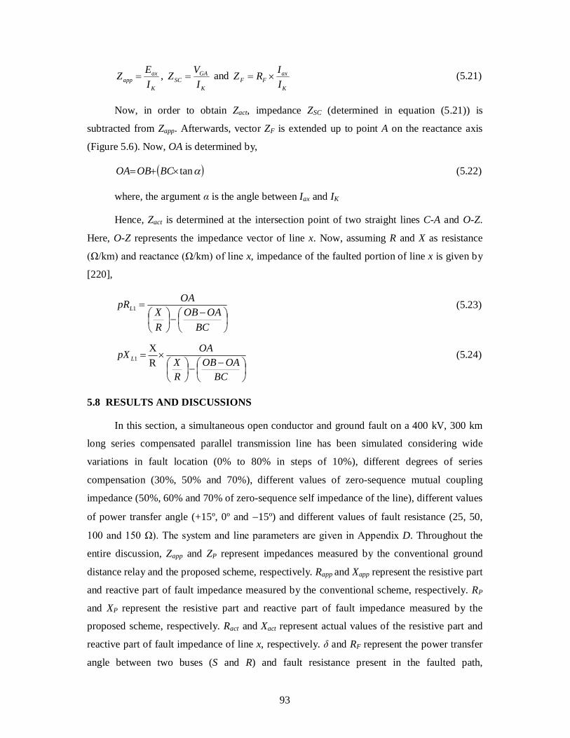
IRZ (5.21)
Now, in order to obtain Zact, impedance ZSC (determined in equation (5.21)) is
subtracted from Zapp. Afterwards, vector ZF is extended up to point A on the reactance axis
(Figure 5.6). Now, OA is determined by,
tan BCOBOA (5.22)
where, the argument α is the angle between Iax and IK
Hence, Zact is determined at the intersection point of two straight lines C-A and O-Z.
Here, O-Z represents the impedance vector of line x. Now, assuming R and X as resistance
(Ω/km) and reactance (Ω/km) of line x, impedance of the faulted portion of line x is given by
[220],
1
BCOAOB
RX
OApRL (5.23)
BCOAOB
RX
OApX L RX 1 (5.24)
5.8 RESULTS AND DISCUSSIONS
In this section, a simultaneous open conductor and ground fault on a 400 kV, 300 km
long series compensated parallel transmission line has been simulated considering wide
variations in fault location (0% to 80% in steps of 10%), different degrees of series
compensation (30%, 50% and 70%), different values of zero-sequence mutual coupling
impedance (50%, 60% and 70% of zero-sequence self impedance of the line), different values
of power transfer angle (+15º, 0º and 15º) and different values of fault resistance (25, 50,
100 and 150 Ω). The system and line parameters are given in Appendix D. Throughout the
entire discussion, Zapp and ZP represent impedances measured by the conventional ground
distance relay and the proposed scheme, respectively. Rapp and Xapp represent the resistive part
and reactive part of fault impedance measured by the conventional scheme, respectively. RP
and XP represent the resistive part and reactive part of fault impedance measured by the
proposed scheme, respectively. Ract and Xact represent actual values of the resistive part and
reactive part of fault impedance of line x, respectively. δ and RF represent the power transfer
angle between two buses (S and R) and fault resistance present in the faulted path,
94
respectively. KC represents the degree of series compensation (in percent) provided to each
line. It is defined as the ratio of capacitive reactance of series capacitor (XC) connected to the
line to the inductive reactance (X) of the complete section of the line. εRapp and εXapp indicate
the percentage error in the measurement of resistive part and reactive part of the fault
impedance given by the conventional scheme, respectively. εRP and εXP indicate the
percentage error in the measurement of resistive part and reactive part of the fault impedance
given by the proposed scheme, respectively. These errors are defined as follows:
% 100
act
actappRapp R
RR , % 100
act
actappXapp X
XX (5.25)
% 100
act
actPRP R
RR , % 100
act
actPXP X
XX (5.26)
The simulation results are discussed in the next subsections.
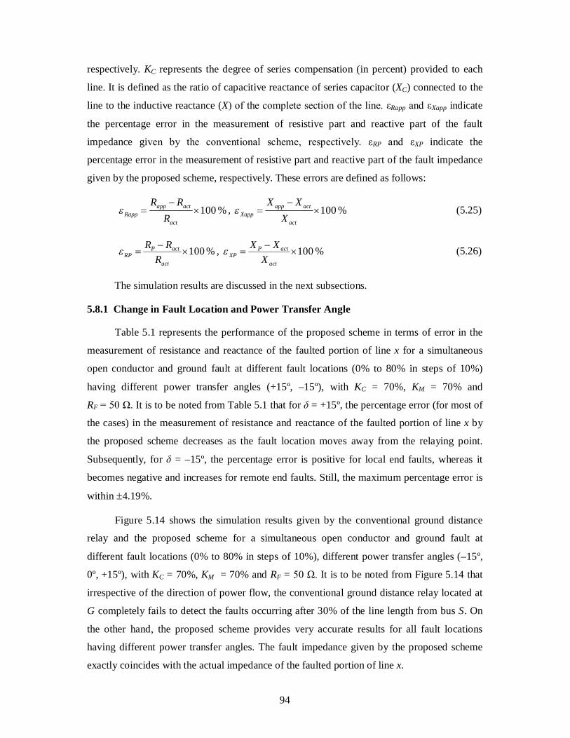
5.8.1 Change in Fault Location and Power Transfer Angle
Table 5.1 represents the performance of the proposed scheme in terms of error in the
measurement of resistance and reactance of the faulted portion of line x for a simultaneous
open conductor and ground fault at different fault locations (0% to 80% in steps of 10%)
having different power transfer angles (+15º, –15º), with KC = 70%, KM = 70% and
RF = 50 Ω. It is to be noted from Table 5.1 that for δ = +15º, the percentage error (for most of
the cases) in the measurement of resistance and reactance of the faulted portion of line x by
the proposed scheme decreases as the fault location moves away from the relaying point.
Subsequently, for δ = –15º, the percentage error is positive for local end faults, whereas it
becomes negative and increases for remote end faults. Still, the maximum percentage error is
within 4.19%.
Figure 5.14 shows the simulation results given by the conventional ground distance
relay and the proposed scheme for a simultaneous open conductor and ground fault at
different fault locations (0% to 80% in steps of 10%), different power transfer angles (–15º,
0º, +15º), with KC = 70%, KM = 70% and RF = 50 Ω. It is to be noted from Figure 5.14 that
irrespective of the direction of power flow, the conventional ground distance relay located at
G completely fails to detect the faults occurring after 30% of the line length from bus S. On
the other hand, the proposed scheme provides very accurate results for all fault locations
having different power transfer angles. The fault impedance given by the proposed scheme
exactly coincides with the actual impedance of the faulted portion of line x.
95
Table 5.1 Effect of change in p and δ on resistance and reactance measurement
p (%)
Ract (Ω)
Xact (Ω)
δ = +15º δ = 15º RP (Ω)
εRP (%)
XP (Ω)
εXP (%)
RP (Ω)
εRP (%)
XP (Ω)
εXP (%)
0 0 0 0.1 1.06 0.11 1.18 10 0.994 10.27 1.04 4.16 10.7 4.19 1.02 2.65 10.51 2.34 20 1.987 20.54 2.05 3.15 21.16 3.02 1.99 0.13 20.52 0.10 30 2.981 30.81 3.03 1.64 31.33 1.69 2.93 1.71 30.26 1.79 40 3.975 41.08 4.02 1.14 41.5 1.02 3.87 2.64 40.05 2.51 50 4.969 51.35 5.01 0.84 51.76 0.80 4.83 2.79 49.93 2.77 60 5.962 61.62 6.02 0.97 62.19 0.93 5.8 2.72 59.95 2.71 70 6.956 71.89 7.04 1.21 72.73 1.17 6.75 2.96 69.73 3.00 80 7.950 82.16 7.99 0.51 82.53 0.45 7.67 3.52 79.31 3.47
Figure 5.14 Fault impedance measurement with varying p and δ
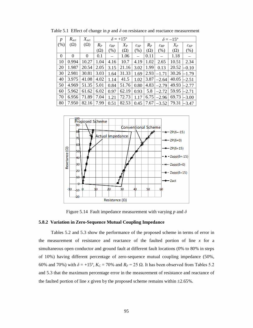
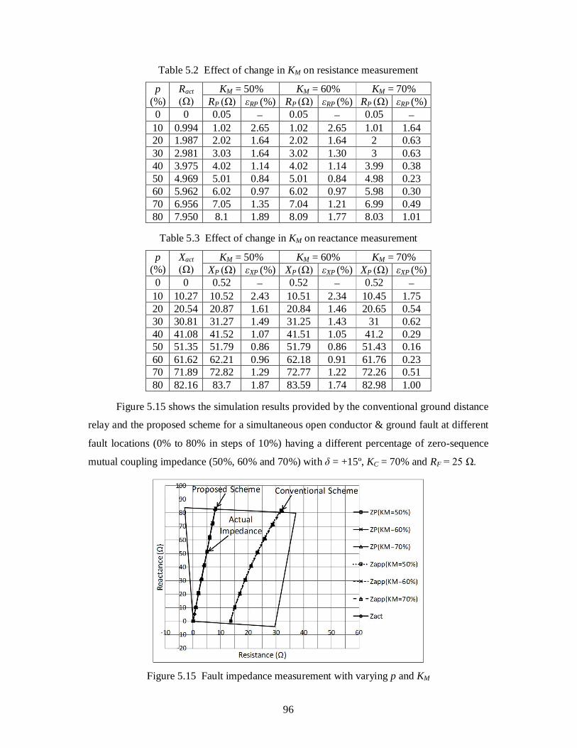
5.8.2 Variation in Zero-Sequence Mutual Coupling Impedance
Tables 5.2 and 5.3 show the performance of the proposed scheme in terms of error in
the measurement of resistance and reactance of the faulted portion of line x for a
simultaneous open conductor and ground fault at different fault locations (0% to 80% in steps
of 10%) having different percentage of zero-sequence mutual coupling impedance (50%,
60% and 70%) with δ = +15º, KC = 70% and RF = 25 Ω. It has been observed from Tables 5.2
and 5.3 that the maximum percentage error in the measurement of resistance and reactance of
the faulted portion of line x given by the proposed scheme remains within 2.65%.
96
Table 5.2 Effect of change in KM on resistance measurement
p (%)
Ract (Ω)
KM = 50% KM = 60% KM = 70% RP (Ω) εRP (%) RP (Ω) εRP (%) RP (Ω) εRP (%)
0 0 0.05 0.05 0.05 10 0.994 1.02 2.65 1.02 2.65 1.01 1.64 20 1.987 2.02 1.64 2.02 1.64 2 0.63 30 2.981 3.03 1.64 3.02 1.30 3 0.63 40 3.975 4.02 1.14 4.02 1.14 3.99 0.38 50 4.969 5.01 0.84 5.01 0.84 4.98 0.23 60 5.962 6.02 0.97 6.02 0.97 5.98 0.30 70 6.956 7.05 1.35 7.04 1.21 6.99 0.49 80 7.950 8.1 1.89 8.09 1.77 8.03 1.01
Table 5.3 Effect of change in KM on reactance measurement
p (%)
Xact (Ω)
KM = 50% KM = 60% KM = 70% XP (Ω) εXP (%) XP (Ω) εXP (%) XP (Ω) εXP (%)
0 0 0.52 0.52 0.52 10 10.27 10.52 2.43 10.51 2.34 10.45 1.75 20 20.54 20.87 1.61 20.84 1.46 20.65 0.54 30 30.81 31.27 1.49 31.25 1.43 31 0.62 40 41.08 41.52 1.07 41.51 1.05 41.2 0.29 50 51.35 51.79 0.86 51.79 0.86 51.43 0.16 60 61.62 62.21 0.96 62.18 0.91 61.76 0.23 70 71.89 72.82 1.29 72.77 1.22 72.26 0.51 80 82.16 83.7 1.87 83.59 1.74 82.98 1.00
Figure 5.15 shows the simulation results provided by the conventional ground distance
relay and the proposed scheme for a simultaneous open conductor & ground fault at different
fault locations (0% to 80% in steps of 10%) having a different percentage of zero-sequence
mutual coupling impedance (50%, 60% and 70%) with δ = +15º, KC = 70% and RF = 25 Ω.
Figure 5.15 Fault impedance measurement with varying p and KM
97
It is to be noted from Figure 5.15 that the loci of fault impedance provided by the
conventional ground distance relay located at G are far away from the actual impedance
locus. On the other hand, the loci of fault impedance of the proposed scheme get
superimposed on the actual impedance locus.
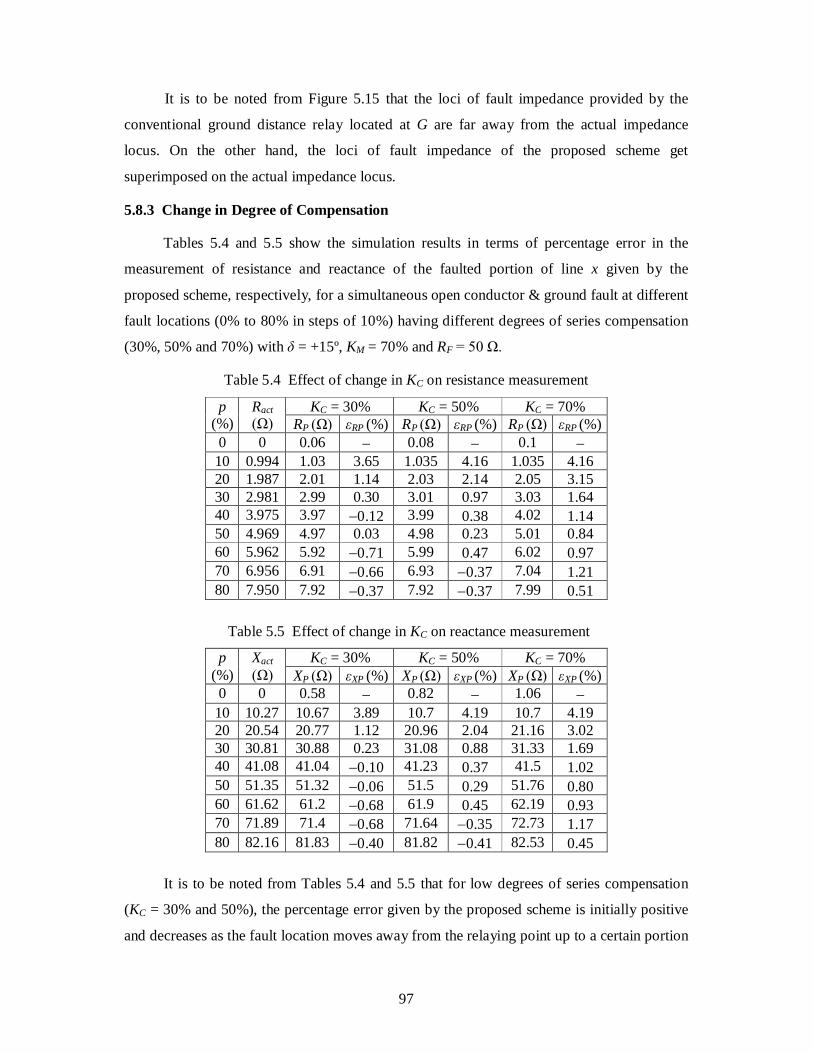
5.8.3 Change in Degree of Compensation
Tables 5.4 and 5.5 show the simulation results in terms of percentage error in the
measurement of resistance and reactance of the faulted portion of line x given by the
proposed scheme, respectively, for a simultaneous open conductor & ground fault at different
fault locations (0% to 80% in steps of 10%) having different degrees of series compensation
(30%, 50% and 70%) with δ = +15º, KM = 70% and RF = 50 Ω.
Table 5.4 Effect of change in KC on resistance measurement
p (%)
Ract (Ω)
KC = 30% KC = 50% KC = 70% RP (Ω) εRP (%) RP (Ω) εRP (%) RP (Ω) εRP (%)
0 0 0.06 0.08 0.1 10 0.994 1.03 3.65 1.035 4.16 1.035 4.16 20 1.987 2.01 1.14 2.03 2.14 2.05 3.15 30 2.981 2.99 0.30 3.01 0.97 3.03 1.64 40 3.975 3.97 0.12 3.99 0.38 4.02 1.14 50 4.969 4.97 0.03 4.98 0.23 5.01 0.84 60 5.962 5.92 0.71 5.99 0.47 6.02 0.97 70 6.956 6.91 0.66 6.93 0.37 7.04 1.21 80 7.950 7.92 0.37 7.92 0.37 7.99 0.51
Table 5.5 Effect of change in KC on reactance measurement
p (%)
Xact (Ω)
KC = 30% KC = 50% KC = 70% XP (Ω) εXP (%) XP (Ω) εXP (%) XP (Ω) εXP (%)
0 0 0.58 0.82 1.06 10 10.27 10.67 3.89 10.7 4.19 10.7 4.19 20 20.54 20.77 1.12 20.96 2.04 21.16 3.02 30 30.81 30.88 0.23 31.08 0.88 31.33 1.69 40 41.08 41.04 0.10 41.23 0.37 41.5 1.02 50 51.35 51.32 0.06 51.5 0.29 51.76 0.80 60 61.62 61.2 0.68 61.9 0.45 62.19 0.93 70 71.89 71.4 0.68 71.64 0.35 72.73 1.17 80 82.16 81.83 0.40 81.82 0.41 82.53 0.45
It is to be noted from Tables 5.4 and 5.5 that for low degrees of series compensation
(KC = 30% and 50%), the percentage error given by the proposed scheme is initially positive
and decreases as the fault location moves away from the relaying point up to a certain portion
98
of line length (say p = 30% for KC = 30% and p = 60% for KC = 50%). Afterward, it becomes
negative for remote end faults. Further, for a high degree of series compensation (KC = 70%),
as the fault location moves away from the relaying point, the percentage error in the
measurement of resistance and reactance of the faulted portion of line x by the proposed
scheme decreases. However, the percentage error for all the cases stays within 4.19%.
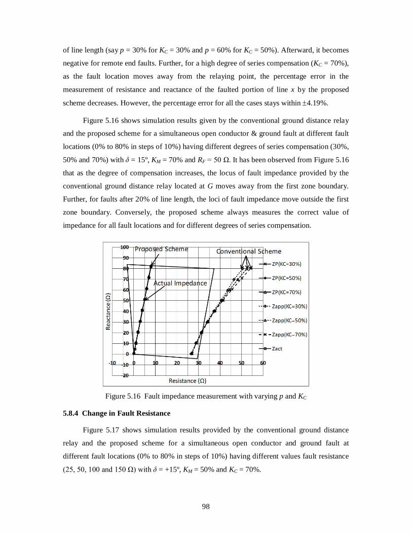
Figure 5.16 shows simulation results given by the conventional ground distance relay
and the proposed scheme for a simultaneous open conductor & ground fault at different fault
locations (0% to 80% in steps of 10%) having different degrees of series compensation (30%,
50% and 70%) with δ = 15º, KM = 70% and RF = 50 Ω. It has been observed from Figure 5.16
that as the degree of compensation increases, the locus of fault impedance provided by the
conventional ground distance relay located at G moves away from the first zone boundary.
Further, for faults after 20% of line length, the loci of fault impedance move outside the first
zone boundary. Conversely, the proposed scheme always measures the correct value of
impedance for all fault locations and for different degrees of series compensation.
Figure 5.16 Fault impedance measurement with varying p and KC
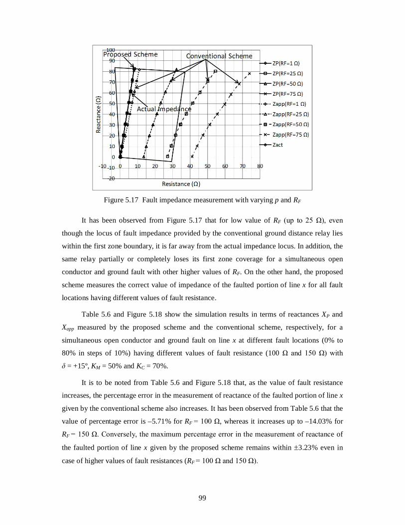
5.8.4 Change in Fault Resistance
Figure 5.17 shows simulation results provided by the conventional ground distance
relay and the proposed scheme for a simultaneous open conductor and ground fault at
different fault locations (0% to 80% in steps of 10%) having different values fault resistance
(25, 50, 100 and 150 Ω) with δ = +15º, KM = 50% and KC = 70%.
99
Figure 5.17 Fault impedance measurement with varying p and RF
It has been observed from Figure 5.17 that for low value of RF (up to 25 Ω), even
though the locus of fault impedance provided by the conventional ground distance relay lies
within the first zone boundary, it is far away from the actual impedance locus. In addition, the
same relay partially or completely loses its first zone coverage for a simultaneous open
conductor and ground fault with other higher values of RF. On the other hand, the proposed
scheme measures the correct value of impedance of the faulted portion of line x for all fault
locations having different values of fault resistance.
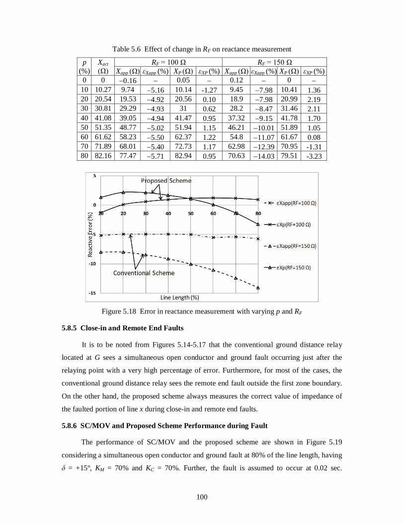
Table 5.6 and Figure 5.18 show the simulation results in terms of reactances XP and
Xapp measured by the proposed scheme and the conventional scheme, respectively, for a
simultaneous open conductor and ground fault on line x at different fault locations (0% to
80% in steps of 10%) having different values of fault resistance (100 Ω and 150 Ω) with
δ = +15º, KM = 50% and KC = 70%.
It is to be noted from Table 5.6 and Figure 5.18 that, as the value of fault resistance
increases, the percentage error in the measurement of reactance of the faulted portion of line x
given by the conventional scheme also increases. It has been observed from Table 5.6 that the
value of percentage error is –5.71% for RF = 100 Ω, whereas it increases up to –14.03% for
RF = 150 Ω. Conversely, the maximum percentage error in the measurement of reactance of
the faulted portion of line x given by the proposed scheme remains within 3.23% even in
case of higher values of fault resistances (RF = 100 Ω and 150 Ω).
100
Table 5.6 Effect of change in RF on reactance measurement
p (%)
Xact (Ω)
RF = 100 Ω RF = 150 Ω Xapp (Ω) εXapp (%) XP (Ω) εXP (%) Xapp (Ω) εXapp (%) XP (Ω) εXP (%)
0 0 0.16 0.05 0.12 0 10 10.27 9.74 5.16 10.14 -1.27 9.45 7.98 10.41 1.36 20 20.54 19.53 4.92 20.56 0.10 18.9 7.98 20.99 2.19 30 30.81 29.29 4.93 31 0.62 28.2 8.47 31.46 2.11 40 41.08 39.05 4.94 41.47 0.95 37.32 9.15 41.78 1.70 50 51.35 48.77 5.02 51.94 1.15 46.21 10.01 51.89 1.05 60 61.62 58.23 5.50 62.37 1.22 54.8 11.07 61.67 0.08 70 71.89 68.01 5.40 72.73 1.17 62.98 12.39 70.95 -1.31 80 82.16 77.47 5.71 82.94 0.95 70.63 14.03 79.51 -3.23
Figure 5.18 Error in reactance measurement with varying p and RF
5.8.5 Close-in and Remote End Faults
It is to be noted from Figures 5.14-5.17 that the conventional ground distance relay
located at G sees a simultaneous open conductor and ground fault occurring just after the
relaying point with a very high percentage of error. Furthermore, for most of the cases, the
conventional ground distance relay sees the remote end fault outside the first zone boundary.
On the other hand, the proposed scheme always measures the correct value of impedance of
the faulted portion of line x during close-in and remote end faults.
5.8.6 SC/MOV and Proposed Scheme Performance during Fault
The performance of SC/MOV and the proposed scheme are shown in Figure 5.19
considering a simultaneous open conductor and ground fault at 80% of the line length, having
δ = +15º, KM = 70% and KC = 70%. Further, the fault is assumed to occur at 0.02 sec.
101
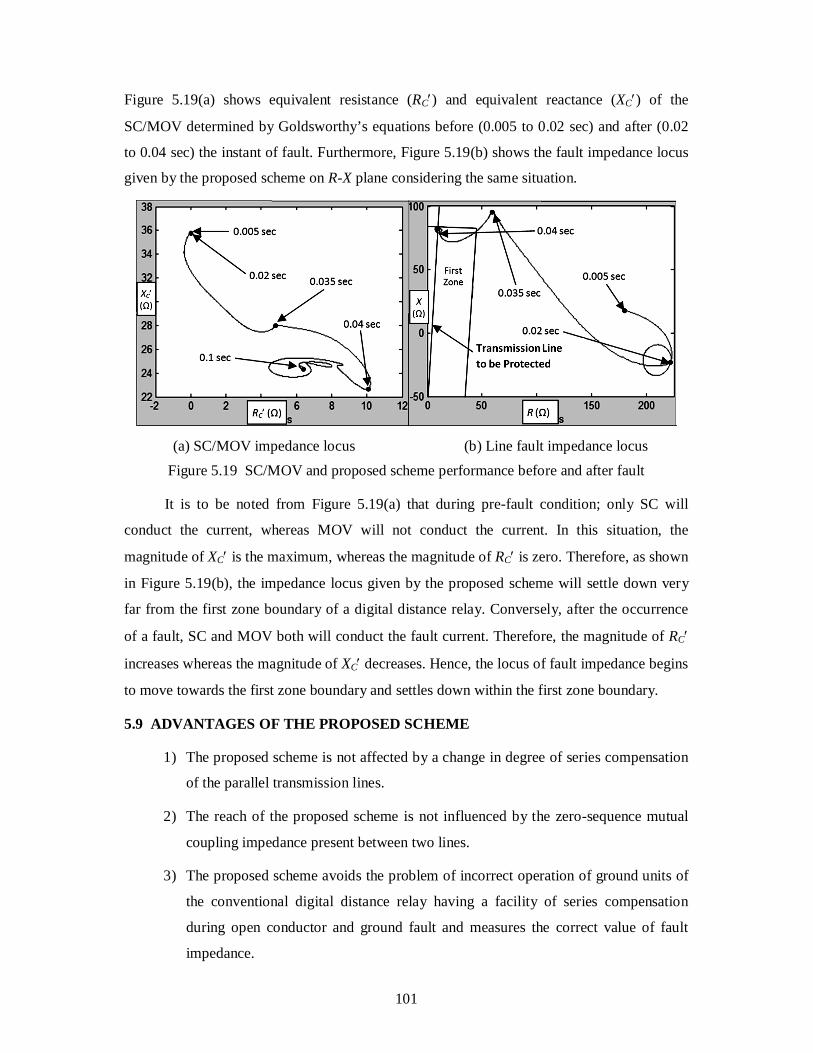
Figure 5.19(a) shows equivalent resistance (RC) and equivalent reactance (XC) of the
SC/MOV determined by Goldsworthy’s equations before (0.005 to 0.02 sec) and after (0.02
to 0.04 sec) the instant of fault. Furthermore, Figure 5.19(b) shows the fault impedance locus
given by the proposed scheme on R-X plane considering the same situation.
(a) SC/MOV impedance locus (b) Line fault impedance locus
Figure 5.19 SC/MOV and proposed scheme performance before and after fault
It is to be noted from Figure 5.19(a) that during pre-fault condition; only SC will
conduct the current, whereas MOV will not conduct the current. In this situation, the
magnitude of XC is the maximum, whereas the magnitude of RC is zero. Therefore, as shown
in Figure 5.19(b), the impedance locus given by the proposed scheme will settle down very
far from the first zone boundary of a digital distance relay. Conversely, after the occurrence
of a fault, SC and MOV both will conduct the fault current. Therefore, the magnitude of RC
increases whereas the magnitude of XC decreases. Hence, the locus of fault impedance begins
to move towards the first zone boundary and settles down within the first zone boundary.
5.9 ADVANTAGES OF THE PROPOSED SCHEME
1) The proposed scheme is not affected by a change in degree of series compensation
of the parallel transmission lines.
2) The reach of the proposed scheme is not influenced by the zero-sequence mutual
coupling impedance present between two lines.
3) The proposed scheme avoids the problem of incorrect operation of ground units of
the conventional digital distance relay having a facility of series compensation
during open conductor and ground fault and measures the correct value of fault
impedance.
102
4) The proposed scheme is not affected by the variations in the system loading
conditions and measures the correct value of fault impedance for different values of
the power transfer angles.
5) The proposed scheme is said to be accurate and robust against wide variations in
system and fault parameters, since the value of percentage error is found to be
within 4.19%.
5.10 CONCLUSION
A new digital distance relaying scheme presented in this chapter provides adequate
protection to series compensated parallel transmission lines during a simultaneous open
conductor and ground fault. The proposed scheme is based on derivation of the compensated
values of impedance using the symmetrical components theory. It measures the correct value
of fault impedance for different fault locations, different values of fault resistance, various
zero-sequence mutual coupling impedance, different degrees of series compensation and
various system loading conditions. Further, it does not require remote end data. A
comparative evaluation of the proposed scheme and the conventional scheme indicates that
the proposed scheme is highly accurate and robust against wide variations in system and fault
parameters as its percentage error is within 4.19%.