Embed Size (px)
Citation preview
Final Feasibility Report Page 5-1
Feasibility study for two-laning of Bhawi-Pipar-Khimsar (H-IV) STUP Consultants Pvt. Ltd.
CHAPTER – 5
DESIGN STANDARD AND IMPROVEMENT PROPOSALS
5.1 General
This chapter describes the various improvement proposals and their necessities to
upgrade the existing carriageway facility of project road into two lanes with or
without paved shoulder in accordance to the Indian standard configuration and
design standards proposed for the project road. These improvement proposals are
based on the findings of various engineering survey, investigations and analysis
carried out on the project roads such as Traffic Survey and Analysis (Chapter-3),
Inventory Data and Pavement Investigations (Chapter-4)‘Manual of Standards &
Specifications for Two Laning (IRC:SP:73-2007)’.
The improvement proposals for proposed widening include the provisions for the
following major items:
a) Curvature Improvement
b) Realignment
c) Widening Proposal
d) Proposed Pavement Design & Overlay Design
e) Cross Drainage Structures
f) Traffic Control and Safety Measures
g) Miscellaneous
5.2 Design Standards
5.2.1 Summary
Following is a summary of the recommended design standards proposed to be
adopted for the project road:
Final Feasibility Report Page 5-2
Feasibility study for two-laning of Bhawi-Pipar-Khimsar (H-IV) STUP Consultants Pvt. Ltd.
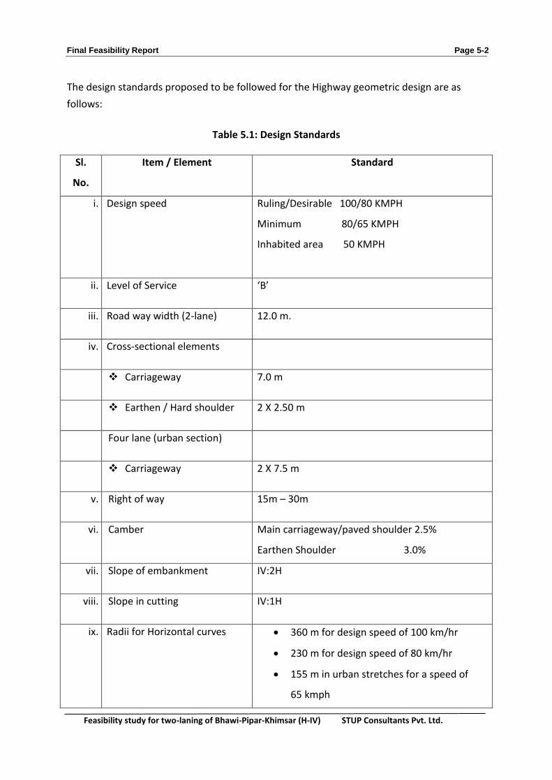
The design standards proposed to be followed for the Highway geometric design are as
follows:
Table 5.1: Design Standards
Sl.
No.
Item / Element Standard
i. Design speed
Ruling/Desirable 100/80 KMPH
Minimum 80/65 KMPH
Inhabited area 50 KMPH
ii. Level of Service ‘B’
iii. Road way width (2-lane) 12.0 m.
iv. Cross-sectional elements
Carriageway 7.0 m
Earthen / Hard shoulder 2 X 2.50 m
Four lane (urban section)
Carriageway 2 X 7.5 m
v. Right of way 15m – 30m
vi. Camber Main carriageway/paved shoulder 2.5%
Earthen Shoulder 3.0%
vii. Slope of embankment IV:2H
viii. Slope in cutting IV:1H
ix. Radii for Horizontal curves 360 m for design speed of 100 km/hr
230 m for design speed of 80 km/hr
155 m in urban stretches for a speed of
65 kmph

Final Feasibility Report Page 5-3
Feasibility study for two-laning of Bhawi-Pipar-Khimsar (H-IV) STUP Consultants Pvt. Ltd.
Sl.
No.
Item / Element Standard
x. Ruling Gradient 3.3% for plain & rolling terrain
xi. Minimum length of vertical
curves
60m for design speed of 100 km/hr
50m for design speed of 80 km/hr
i. Super elevation 5%
ii. Friction factor 0.15 - 0.2%
iii. Sight distance(SD) Speed (KPH) ISD (m)
100 360
80 260
65 180
Geometric Design
5.2.2 General
Geometric design of a highway is the process whereby the layout of the road in
specific terrain is designed to meet the needs of the road users keeping in view the
road function, type and volume of traffic, potential traffic hazards and safety as well
as convenience of the road users. The principal areas of control for fulfilment of this
objective are- the horizontal alignment, vertical alignment and the road cross-
section.
The Consultants have referred to the design standards and general features as per
Manual of Specifications and Standards for two laning of highways through Public
Private Partnership Published by IRC(IRC:SP-73-2007).
5.2.3 Design Speed
The project road highway passes through Plain/ rolling terrain. Rural highways,
except expressways, are normally designed for speed of 100 km/hr, however
depending on terrain and whether the design is for new alignment or reconstruction
of an existing facility, the design speed is determined as per the site requirement.
Final Feasibility Report Page 5-4
Feasibility study for two-laning of Bhawi-Pipar-Khimsar (H-IV) STUP Consultants Pvt. Ltd.
5.2.4 Cross Sectional Elements
5.2.4.1 Roadway Width for Two lane Highways
Adequate roadway width will be provided for the requisite number of traffic lanes
besides the shoulders. As specified in the above mentioned manual in general, for
highways the shoulder width shall be 2.5 m, and lane width 3.5 m per lane.
5.2.4.2 Shoulders
Shoulders are a critical element of the roadway cross section. These provide
recovery area for errant vehicles; a refuge for stopped or disabled vehicles; and
access for emergency and maintenance vehicles. Shoulders can also provide an
opportunity to improve sight distance through cut sections.
As per manual normal shoulders width shall be 2.50 m in open and isolated built up
area.
The Consultants propose to adopt an outer shoulder width of minimum 2.5 m
shoulder for the project highway. However, the configuration of shoulder depends
upon the traffic capacity on the section of road. Accordingly, 2.5 m wide unpaved
shoulders will be provided.
5.2.4.3 Pavement Camber (Cross-fall)
As per the provisions of the Manual a cross fall of 2.50% on bituminous roads and 2%
on cement concrete road with low annual rainfall is being adopted.
5.2.4.4 Right of Way (ROW)
A ROW of 18 m is being proposed throughout on existing road and 30 m along the
re-alignment
5.2.4.5 Typical Cross sections
Typical cross sections are prepared to guide the widening scheme of the proposed
highway in different conditions. The broad conditions considered are :
Type of terrain

Final Feasibility Report Page 5-5
Feasibility study for two-laning of Bhawi-Pipar-Khimsar (H-IV) STUP Consultants Pvt. Ltd.
Existing pavement condition and width
Realignment / Bypass
Land use along the highway (Built up area / open area)
Lane configuration
Treatment over existing road
Based on the above considerations, following typical cross sections have been developed.
Table 5.2: Typical Cross Sections
S. No. Type Feature Applicable to
1 1
Widening from Single Lane to 2-
lane alongwith shoulders covered
with 150 mm thick layer of
granular material
Where the existing carriageway (3.0 m to 3.75 m wide) is to be widened to 7.0 m wide carriageway.
2 2
Widening and strengthening of
Single Lane to 2-lanewith paved
shoulders in built up area
Where the existing carriageway 3.0 m to 3.75m wide is to be widened to 7.0 m wide carriageway in Urban stretch
5 5 Bypass / Realignment Re-alignment / bypasses
* The stretch having Intermediate Lane falls in the common position with H-III.
5.2.5 Horizontal Alignment
5.2.5.1 General
Though it is necessary to improve the sub-standard horizontal curves for the safety of the
traffic. Therefore, the existing sub-standard curves have to be improved to have minimum
radii of 230 m in rural area or to the extent possible within ROW. In the stretches passing
through urban areas sub-standard curves are to be improved to have a radius of 155 m in
general.
Final Feasibility Report Page 5-6
Feasibility study for two-laning of Bhawi-Pipar-Khimsar (H-IV) STUP Consultants Pvt. Ltd.
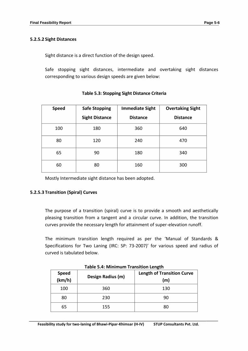
5.2.5.2 Sight Distances
Sight distance is a direct function of the design speed.
Safe stopping sight distances, intermediate and overtaking sight distances
corresponding to various design speeds are given below:
Table 5.3: Stopping Sight Distance Criteria
Mostly Intermediate sight distance has been adopted.
5.2.5.3 Transition (Spiral) Curves
The purpose of a transition (spiral) curve is to provide a smooth and aesthetically
pleasing transition from a tangent and a circular curve. In addition, the transition
curves provide the necessary length for attainment of super-elevation runoff.
The minimum transition length required as per the ‘Manual of Standards &
Specifications for Two Laning (IRC: SP: 73-2007)’ for various speed and radius of
curved is tabulated below.
Table 5.4: Minimum Transition Length
Speed
(km/h) Design Radius (m)
Length of Transition Curve
(m)
100 360 130
80 230 90
65 155 80
Speed
Safe Stopping
Sight Distance
Immediate Sight
Distance
Overtaking Sight
Distance
100 180 360 640
80 120 240 470
65 90 180 340
60 80 160 300

Final Feasibility Report Page 5-7
Feasibility study for two-laning of Bhawi-Pipar-Khimsar (H-IV) STUP Consultants Pvt. Ltd.
It is proposed to adopt transition curve as per the above table in general site
conditions...
5.2.5.4 Super-elevation
The limiting value of the super-elevation on the project highway in plain terrain is
proposed to be 5% as per IRC: SP 73 -2007.
5.2.6 Vertical Alignment
5.2.6.1 General
The vertical alignment should produce a smooth longitudinal profile consistent with
standard of the road and terrain. Where it maybe possible horizontal and vertical
curvature should be so combined that the safety and operational efficiency of the
road is enhanced.
5.2.6.2 Gradients
The IRC: 73-1980 geometric design standards provide ruling vertical grades of 3.3%
to 5.0% for plain terrains. However, for the project highway, maximum grade
adopted is 1.5%.
5.2.6.3 Vertical Curves
When a motorised traffic travelling along upgrade is to move on to low grade or vice
version, a change of direction of motion in the vertical plane is involved. If the
change is not effected gradually the vehicle will be subjected to shock and occupants
of the vehicle will experience discomfort. Hence a vertical curve is introduced to
ease off the change in gradient. The vertical curves are designed for intermediate
sight distance.

Final Feasibility Report Page 5-8
Feasibility study for two-laning of Bhawi-Pipar-Khimsar (H-IV) STUP Consultants Pvt. Ltd.
Minimum Length of Vertical Curve: The minimum length of vertical curve and the
maximum grade change not requiring a vertical curve are summarized below:
Table5.5: Minimum Length of Vertical Curve
Design Speed
(Km/hr)
Maximum grade change
not requiring a vertical
curve (in %)
Minimum length of
vertical curve (m)
100 0.5 40
80 0.6 50
1. Summit or Crest Curves
A curve with convexity upwards is called a Summit curve. The design of Summit
curve is mostly governed by considerations of sight distance. In general a simple
parabolic curve is used for design of summit curve.
There are two case of calculation of length of summit curve for various sight
distances:
Case-I: When the length of curve is greater than the required sight distance.
Case-II: When the length of curve is less than the required sight distance.
The minimum K values for Summit or Crest curves, in accordance with IRC –SP23
(1993) design guidelines for the case-I length of curve is greater than sight distance
are tabulated below:
Table 5.6: K value
Design Speed
km/h
Minimum K value
Stopping Sight
Distance
Intermediate Sight
Distance
Over Taking
Sight Distance
100 73.6 135 426.7
80 32.6 60 230.1
65 18.4 33.8 93.7
Final Feasibility Report Page 5-9
Feasibility study for two-laning of Bhawi-Pipar-Khimsar (H-IV) STUP Consultants Pvt. Ltd.
The curve length which is calculated based on the above K values is subjected to the
minimum length of the vertical curve described above.
However, the above values of ‘K’ are the minimum and consultant has adopted more
than the above values.
2. Valley or Sag Curves
There are number of criteria available for establishing the length of Valley Curve. Out
of that the most common one is
i) Headlight sight distance
ii) Rider comfort
To calculate the length following criteria is applied:
i) Height of headlight above road surface is 0.75
ii) The useful beam of headlight is up to one degree upwards from the grade
of the roads.
iii) The height of the object is nil
The minimum K values for valley or sag curves, in accordance with IRC –SP23 (1993)
design guidelines are 41.5, 25.3 and 17.4 for design speeds of100 km/hr, 80 km/hr
and65 km/hr respectively. The curve length which is calculated based on the above K
values is subjected to the minimum length of the vertical curve described above.
However, the above values of ‘K’ are minimum and consultant has adopted more
than the above values.
Widening Scheme:
In order to meet future traffic requirement the existing carriageway is proposed to be
upgraded to achieve high speed of travel with comfort and safety. Widening scheme is
studied as follows.

Final Feasibility Report Page 5-10
Feasibility study for two-laning of Bhawi-Pipar-Khimsar (H-IV) STUP Consultants Pvt. Ltd.
Widening the existing lane to 2-lane paved shoulder in built up area only with formation
width of 12m including realignments / Bypasses to achieve the design speed of 100kmph
ruling and 80kmph minimum.
Table: 5.7
S.
No. Homogeneous Section Lane Configuration
1
Km 0 -31
(Bhawi – Sathin, including
common portion with H-III)
2-Lane With 2.5 m wide shoulder covered with
150 mm thick granular material.
2 Km 31 – 71
(Sathin - Palri)
2-Lane with 2.50 m wide shoulder covered
with 150 mm thick granular material.
3
Km 75 - 97
(Lawari Piou – Khimsar,
including common portion
with H-II)
2-Lane with 2.50 m wide shoulder covered
with 150 mm thick granular material.
Above stretches also include the stretches passing through the towns details given below
where the lane configuration will be two lane with 1.5 m wide paved shoulder on either
side alongwith 1 m wide earthen shoulder over layed with 150 mm thick granular material.
S. No. Name of Township
Location Ch (km – km)
Length (m)
Pavement type
Remarks
1 Ghana Mangra 5.400 – 6.170 0.77 CC/BT Partly CC
2 Tilwasni 7.000 – 8.200 1.20 CC/BT Partly CC
3 Selari 10.480 – 11.500 1.02 CC/BT Partly CC
4 Pipar 18.500 – 20.850 2.35 CC/BT Partly CC
5 Ratkuria 41.150 – 42.000 0.85 CC/BT Partly CC
6 Bhopalgarh 53.900 – 56.900 3.00 CC/BT Partly CC
7 Surpura 62.100 – 63.100 1.00 CC/BT Partly CC
8 Gajsinghpur 79.500- 81.100 1.60 CC/BT Partly CC
9 Mangeria 86.300 – 87.400 1.10 CC/BT Partly CC
10 Dharnawas 92.150 – 93.000 0.85 CC/BT Partly CC
11 Lalawas 95.600 – 96.000 0.40 CC/BT Partly CC

Final Feasibility Report Page 5-11
Feasibility study for two-laning of Bhawi-Pipar-Khimsar (H-IV) STUP Consultants Pvt. Ltd.
Existing Alignment
The project highway taking off from Chainage Km. 59.700 of NH-112 ends at Ch. 217.200 of
NH-65 after running along MDR-90 and passes through the villages Bhawi, Silari, Pipar city,
Sathin, Ratkuriya, Bhopalgarh, Palri Ranawat, Lawari Piou, Gajsinghpura Mangeria, Tadawas,
Lalawas.The project road is located between 26o 13’ 43” and 26o 56’ 38” latitude and 73o 36’
28” and 73o 24’ 07” longitude.
The horizontal alignment is passing through plain rolling terrain. The existing alignment in
some locations especially in built up areas has sharp curve and deficient geometrics the
vertical alignment is generally within lain down standards.
The land along the project road is mostly used for agriculture purposes with some built up
areas. The major built up area along the project road are Pipar, Rathkuria, Bhopalgarh,
Gajsinghpura.
The width of existing carriageway is generally single lane (3.50 m to 3.66 m).
From the preliminary survey it has been found that The Existing ROW varies within 15 to 30
m in most of the open areas. However, after the collection of revenue maps, it is noted that
the existing ROW varies from 8 to 20 m.
Widening Scheme
The existing project highway has multi-dimensional facets with respect to land use and road
geometry and considering all these aspects, the section wise widening scheme based on the
investigations as adopted is given in Table 5.8:
Table 5.8: Widening Scheme
Nature of
widening
Existing Chainage (Km.) Designing Chainage (Km.) Length
(Km)
From To From To
Concentric 0+000.000 0+039.720 0+000.000 0+039.200 39.200
Realignment 0+039.720 0+041.275 0+039.200 0+041.200 2.000
Concentric 0+041.200 0+097.150 0+041.200 0+096.978 55.778
Final Feasibility Report Page 5-12
Feasibility study for two-laning of Bhawi-Pipar-Khimsar (H-IV) STUP Consultants Pvt. Ltd.
Chainage Reference:
The existing km stone available on ground wherever available have been used as
referencing pillar only. The development proposal has been finalised based on Design
chainage system.
Summary of Widening Scheme:
The widening scheme can be summarised as given in Table 5.8
Design Standards, Improvement Proposal and Design
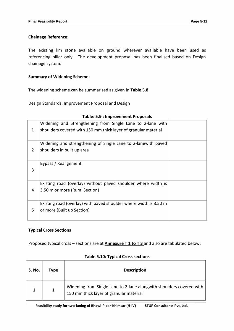
Table: 5.9 : Improvement Proposals
1
Widening and Strengthening from Single Lane to 2-lane with
shoulders covered with 150 mm thick layer of granular material
2
Widening and strengthening of Single Lane to 2-lanewith paved
shoulders in built up area
3
Bypass / Realignment
4
Existing road (overlay) without paved shoulder where width is
3.50 m or more (Rural Section)
5
Existing road (overlay) with paved shoulder where width is 3.50 m
or more (Built up Section)
Typical Cross Sections
Proposed typical cross – sections are at Annexure T 1 to T 3 and also are tabulated below:
Table 5.10: Typical Cross sections
S. No. Type Description
1 1 Widening from Single Lane to 2-lane alongwith shoulders covered with
150 mm thick layer of granular material

Final Feasibility Report Page 5-13
Feasibility study for two-laning of Bhawi-Pipar-Khimsar (H-IV) STUP Consultants Pvt. Ltd.
2 2
Widening and strengthening of Single Lane to 2-lanewith paved
shoulders in built up area
3 3 Bypass / Realignment
Cross Section Schedule
Table: 5.11
S. No.
Proposed Chainage Length
From To (Km.)
TCS - 1
1 2.50 5.40 2.90
2 6.17 7.00 0.83
3 8.20 10.71 2.51
4 11.50 18.60 7.10
5 20.76 39.20 18.44
6 41.20 40.77 -0.43
7 42.00 53.40 11.40
8 56.94 79.50 22.56
9 81.10 92.15 11.05
10 93.00 95.60 2.60

Final Feasibility Report Page 5-14
Feasibility study for two-laning of Bhawi-Pipar-Khimsar (H-IV) STUP Consultants Pvt. Ltd.
TCS - 2
1 5.4 6.17 0.77
2 7 7.41 0.41
3 7.41 8.2 0.79
4 10.71 11.5 0.79
5 18.6 19.48 0.88
6 19.48 20.76 1.28
7 41.15 42 0.85
8 40.77 41.23 0.46
9 53.4 53.93 0.53
10 53.93 56.9 2. 97
11 54.9 55.3 0.4
12 55.3 56.94 1.64
13 79.5 81.1 1.6
14 92.15 93 0.85
15 95.6 96.8 1.2
Final Feasibility Report Page 5-15
Feasibility study for two-laning of Bhawi-Pipar-Khimsar (H-IV) STUP Consultants Pvt. Ltd.
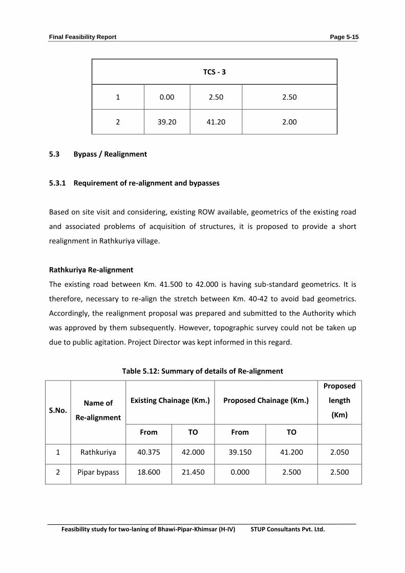
TCS - 3
1 0.00 2.50 2.50
2 39.20 41.20 2.00
5.3 Bypass / Realignment
5.3.1 Requirement of re-alignment and bypasses
Based on site visit and considering, existing ROW available, geometrics of the existing road
and associated problems of acquisition of structures, it is proposed to provide a short
realignment in Rathkuriya village.
Rathkuriya Re-alignment
The existing road between Km. 41.500 to 42.000 is having sub-standard geometrics. It is
therefore, necessary to re-align the stretch between Km. 40-42 to avoid bad geometrics.
Accordingly, the realignment proposal was prepared and submitted to the Authority which
was approved by them subsequently. However, topographic survey could not be taken up
due to public agitation. Project Director was kept informed in this regard.
Table 5.12: Summary of details of Re-alignment
S.No. Name of
Re-alignment
Existing Chainage (Km.) Proposed Chainage (Km.)
Proposed
length
(Km)
From TO From TO
1 Rathkuriya 40.375 42.000 39.150 41.200 2.050
2 Pipar bypass 18.600 21.450 0.000 2.500 2.500

Final Feasibility Report Page 5-16
Feasibility study for two-laning of Bhawi-Pipar-Khimsar (H-IV) STUP Consultants Pvt. Ltd.
Geometric Improvement Design
As per IRCl73-2007, the project highway should be designed with 100 kmpH ruling speed
and 80 KMPH minimum speed for plain terrain and 80 KMPH/65 KMPH for rolling terrain.
However, keeping in view the diverse mix of traffic on the project highway, minimum design
speed of 65 kmph (Radius 155m) has been adopted. In built up areas, the speed has been
restricted to 50 / 40 kmph where there is no scope at all to improve the geometric further
within ROW.
Proposal for New Bridge
There is no proposal to construct the new bridge on the Project Highway.
Proposal for replacement of Existing LC with ROB
The project road crosses railway track at one location (Km 272-60) at Merta Road junction.
As per railway records, the TVU (Train Vehicle Units) at the LC is 67440 as on April 2014.
According to IRC 62- 1976 “Grade Separator should be provided across existing railway
crossing if the product of ADT (Fast vehicle only) and the number of trains passing per day
exceed 50,000. However, the cost of construction of this ROB is not included in the overall
cost of the project.
Cross Drainage Structures
Introduction
Upgrading of the road section from Single Lane /Intermediate Lane to 2-Lane carriageway
involves widening of the existing CD structures. Wherever the new alignment is away from
the existing road, new culverts opposite to the existing ones would be required in the new
alignment. New culverts are also required where the capacities of the existing ones are
inadequate or where the vents/diameters are too small from maintenance point of view.
Repair or replacement of culverts is called for when these are in distressed condition.
Accordingly detailed inventory of all the culverts was made and their conditions survey was
carried out to determine their present conditions.

Final Feasibility Report Page 5-17
Feasibility study for two-laning of Bhawi-Pipar-Khimsar (H-IV) STUP Consultants Pvt. Ltd.
The pipe culverts, which are having diameter less than 1000 mm have been replaced by pipe
of NP4 1200 mm keeping in view the constraints and inadvertence of maintenance. Similarly
the CD structures other than pipes having widths and heights up to one metre have been
proposed to be replaced by 1200 mm diameter pipes or Slab culvert as appropriate to
maintain the vertical profile. All causeways have been proposed to be replaced by new pipe
culverts (2x1.2m dia. / 3x1.2m dia.) as per the hydrology of the area. All other existing cross
drainage structures have simply been recommended for widening / repair / reconstruction.
The schemes for widening or replacement of CD Structure have been prepared based on
available data, visual assessment of the CD structures, the surrounding tell-tale marks of
HFL, local enquiry and the concept mentioned above. Functional cross-section of the culvert
for 2-laning configuration is presented in Typical GADs for Pipe & Slab Culverts is enclosed in
Drawing volume.
Summary of different types of Culverts/CD structures:
Culverts:
Table: 5.13 Details of Cross - Drainage Structure
Pipe Culvert
S.No.
Existing Chainage (km)
Proposed Chainage
(km)
Type of structure
Span Arrangement
(m)
Vertical Clearance
(m)
Road Level (m)
Bed Level (m)
Structure proposed
1 0+000 0+013 Pipe 2X0.90 1.1 267.327 266.382 2 H.P. 1.2m
Dia
Slab Culvert
S.No. Existing
Chainage (km)
Proposed Chainage
(km)
Type of structure
Span Arrangement
(m)
Invert Level
LHS (m)
Invert Level RHS (m)
Soffit Level (m)
Road Level (m)
Structure proposed
1 53+622 51+998 Slab 2X1.10 297.36 297.5 298.9 299.646 To be
widened
2 56+338 55+750 Slab 1X4.0 297.03 297.62 301.97 302.356 To be
widened

Final Feasibility Report Page 5-18
Feasibility study for two-laning of Bhawi-Pipar-Khimsar (H-IV) STUP Consultants Pvt. Ltd.
Causeway
S. No. Existing
Chainage (km)
Proposed Chainage
(km)
Type of structure
Span Arrangement
(m)
Structure proposed
1 5+305 5+315 Cause Way 7.8X98.7 3 H.P. 1.2m Dia
2 12+430 11+973 Cause Way 5.00X40.750 2 H.P. 1.2m Dia
3 42+302 41+500 Cause Way 7.0x85.0 3 H.P. 1.2m Dia
4 47+788 46+396 Cause Way 6.3X77.2 3 H.P. 1.2m Dia
5 48+525 47+139 Cause Way 13.0X91.2 3 H.P. 1.2m Dia
6 49+685 48+248 Cause Way 7.0X61.7 3 H.P. 1.2m Dia
7 58+470 57+884 Cause Way 7.3X20.3 2 H.P. 1.2m Dia
8 59+880 59+332 Cause Way 30X8 2 H.P. 1.2m Dia
9 60+044 59+525 Cause Way 30X8 2 H.P. 1.2m Dia
10 60+225 59+710 Cause Way 30X8 2 H.P. 1.2m Dia
11 61+757 61+363 Cause Way 30X8 2 H.P. 1.2m Dia
12 85+927 Cause Way 7.1x32.9 Chocked
13 On Pipar bypass
0+600 Hume Pipe 2X1.2 2 H.P. 1.2m Dia
14 On Pipar bypass
1+300 Hume Pipe 2X1.2 2 H.P. 1.2m Dia
15 On Pipar bypass
2+000 Hume Pipe 2X1.2 2 H.P. 1.2m Dia
Road Markings, Signs and other safety Devices
5.4 Road Markings
Pavement markings are proposed as per IRC: 35, “Code of Practice for Road
Marking” with edge line, continuity line, stop line, give way lines, diagonal/chevron
markings and zebra crossings etc. The pavement marking shall be of hot applied

Final Feasibility Report Page 5-19
Feasibility study for two-laning of Bhawi-Pipar-Khimsar (H-IV) STUP Consultants Pvt. Ltd.
thermoplastic paint with glass beads as per the MORT&H specification for Road and
Bridge Works, 2013.
5.5 Road Signs
Adequate road signs are proposed for the project road in order to provide advance
information to regulate/control traffic flow and ensure safety of operations. All
normal warning and regulatory road signs will be provided in accordance with IRC-
67-2012. Typical drawings of road signs with its erection details are given in the
drawing volume.
The signs will be of retro reflective sheeting of high intensity grade with
encapsulated lens and fixing details as per clause 801 of MOSRTH Specifications for
Road and Bridge Works, 2013 (5th Revision).
5.6 Kilometre Stone:
Standard Kilometre, 5th kilometre and hectometre stones have been proposed as per
provisions of IRC: 8 and IRC 26. In addition, boundary stones at an interval of 100 m
staggered on each side have been proposed as per IRC: 25.
5.7 Delineators
Delineator provides visual assistance to drivers about the road alignment.
Delineators have been proposed as per guidelines vide IRC 79 “Recommended
Practice for Road Delineators.”
5.8 Miscellaneous Requirements:
Proposal for Bus Shelter
There are no existing Bus Shelter son the project road. However, from the survey of
bus travelling and its stoppages the following locations have been identified for

Final Feasibility Report Page 5-20
Feasibility study for two-laning of Bhawi-Pipar-Khimsar (H-IV) STUP Consultants Pvt. Ltd.
provision of bus shelter on either side. The general layout of bus shelter shall be as
per Cl.13.5.3. of IRC: SP 73-2007.
Table 5.14: Bus Shelter Locations
The above locations are, however, tentative and can be adjusted during construction
in consultation with IE/AE.
5.9 Cattle Crossings:
Though no separate cattle crossings have been proposed, the culverts, however,
having minimum 2m height during dry season may serve as cattle crossings.
5.10 Toll Plazas Stations
Toll plaza location has been strategically identified to collect maximum toll revenue.
In addition, the availability of flat open ground and straight reach to provide clear
visibility, safe distance from intersections and availability of basic facilities for the
personnel employed in toll collection has been considered.
Three Toll Plazas having two lane (plus one lane on each side for oversized vehicles)
are proposed for the entire length of the project road after considering land
S. No.
(Existing Chainage Km.) Proposed Chainage (km)
LHS RHS LHS RHS
1 Ghano-Mangia 6.150 6.250 6.150 6.250
2 Talwasni 7.600 7.350 7.600 7.350
3 Silari 10.750 10.650 10.750 10.650
4 Rathkuria 40.200 40.350 39.800 39+950
5 Bhopalgarh 53.800 53.900 53.734 53.834
6 Surpura Khurd 62.250 61.900 62.178 61.828
7 Palri Ranawat 70+649 70+864 70+574 70+789
8 Gajsinghpur 80+905 80+645 80+743 80+483
9 Mangeria 86+880 86+920 86+720 86+760
10 Dharmawas 92+820 92+880 92+625 92+685
11 Lalawas 95+690 95+780 95+491 95+580

Final Feasibility Report Page 5-21
Feasibility study for two-laning of Bhawi-Pipar-Khimsar (H-IV) STUP Consultants Pvt. Ltd.
availability, stream of traffic, geometric considerations and terrain condition etc.
Proposed locations of toll plazas are given in table below.
A minimum semi-automatic system for toll collection may be adopted. The general
layout of toll plaza shall be as per IRC: SP: 73-2007
Table 5.15: Toll Plaza Location
S. No. Existing Chainage Proposed Chainage of
Project Highway
1 Km. 3.000 (Bhawi- Sathin Section) Km. 3.00
2 Km. 49.400 (Sathin- Palri Section) Km. 48.000
3 Km. 85.700 (Lawari Piou-Khimsar Section) Km. 85.535
5.11 Pavement Design
5.11.1 General
Pavement design basically aims at determining the total thickness of the pavement
structure as well as the thickness of the individual structural components. Different
accepted methods for design are available, such as those of IRC37-2012, AASHTO,
etc. and according to the scope of services the overlay design has been worked out
following the IRC 81-2002.
5.11.2 Project Proposals
The existing project highway has most of single lane (3.0-3.66m wide) There exists
about 1 - 2m wide earthen shoulder on either side of the carriageway. The surface of
the carriageway is generally bituminous except in built up areas where it is partly
cement concrete. The project proposal is to widen the existing carriageway to
standard 2-lane / 2-lane with paved shoulder on both flanked with 2.5m wide
earthen shoulder with top 150mm thick with granular material. In built up area,
1.5m wide paved shoulder have been proposed and 1.0 m wide earthen shoulder on
both sides to be covered with 0.15 m thick granular material.
Final Feasibility Report Page 5-22
Feasibility study for two-laning of Bhawi-Pipar-Khimsar (H-IV) STUP Consultants Pvt. Ltd.
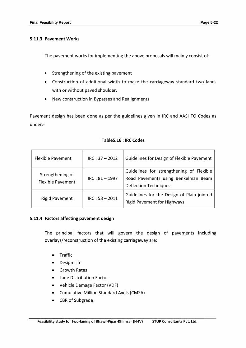
5.11.3 Pavement Works
The pavement works for implementing the above proposals will mainly consist of:
Strengthening of the existing pavement
Construction of additional width to make the carriageway standard two lanes
with or without paved shoulder.
New construction in Bypasses and Realignments
Pavement design has been done as per the guidelines given in IRC and AASHTO Codes as
under:-
Table5.16 : IRC Codes
Flexible Pavement IRC : 37 – 2012 Guidelines for Design of Flexible Pavement
Strengthening of
Flexible Pavement IRC : 81 – 1997
Guidelines for strengthening of Flexible
Road Pavements using Benkelman Beam
Deflection Techniques
Rigid Pavement IRC : 58 – 2011 Guidelines for the Design of Plain jointed
Rigid Pavement for Highways
5.11.4 Factors affecting pavement design
The principal factors that will govern the design of pavements including
overlays/reconstruction of the existing carriageway are:
Traffic
Design Life
Growth Rates
Lane Distribution Factor
Vehicle Damage Factor (VDF)
Cumulative Million Standard Axels (CMSA)
CBR of Subgrade
Final Feasibility Report Page 5-23
Feasibility study for two-laning of Bhawi-Pipar-Khimsar (H-IV) STUP Consultants Pvt. Ltd.
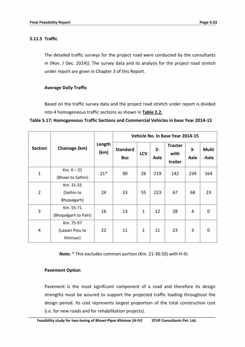
5.11.5 Traffic
The detailed traffic surveys for the project road were conducted by the consultants
in (Nov. / Dec. 2014)). The survey data and its analysis for the project road stretch
under report are given in Chapter 3 of this Report.
Average Daily Traffic
Based on the traffic survey data and the project road stretch under report is divided
into 4 homogeneous traffic sections as shown in Table 2.2.
Table 5.17: Homogeneous Traffic Sections and Commercial Vehicles in base Year 2014-15
Note: * This excludes common portion (Km. 21-30.50) with H-III.
Pavement Option
Pavement is the most significant component of a road and therefore its design
strengths must be assured to support the projected traffic loading throughout the
design period. Its cost represents largest proportion of the total construction cost
(i.e. for new roads and for rehabilitation projects).
Section Chainage (km) Length
(km)
Vehicle No. In Base Year 2014-15
Standard
Bus LCV
2-
Axle
Tractor
with
trailer
3-
Axle
Multi
-Axle
1 Km. 0 – 21
(Bhawi to Sathin) 21* 90 26 219 142 234 164
2
Km. 31-55
(Sathin to
Bhopalgarh)
24 33 55 223 67 68 23
3 Km. 55-71
(Bhopalgarh to Palri) 16 13 1 12 28 4 0
4
Km. 75-97
(Lawari Piou to
Khimsar)
22 11 1 11 23 3 0
Final Feasibility Report Page 5-24
Feasibility study for two-laning of Bhawi-Pipar-Khimsar (H-IV) STUP Consultants Pvt. Ltd.
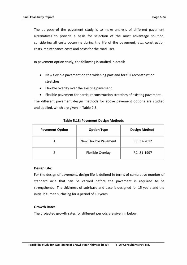
The purpose of the pavement study is to make analysis of different pavement
alternatives to provide a basis for selection of the most advantage solution,
considering all costs occurring during the life of the pavement, viz., construction
costs, maintenance costs and costs for the road user.
In pavement option study, the following is studied in detail:
New flexible pavement on the widening part and for full reconstruction
stretches
Flexible overlay over the existing pavement
Flexible pavement for partial reconstruction stretches of existing pavement.
The different pavement design methods for above pavement options are studied
and applied, which are given in Table 2.3.
Table 5.18: Pavement Design Methods
Pavement Option Option Type Design Method
1 New Flexible Pavement IRC: 37-2012
2 Flexible Overlay IRC: 81-1997
Design Life:
For the design of pavement, design life is defined in terms of cumulative number of
standard axle that can be carried before the pavement is required to be
strengthened. The thickness of sub-base and base is designed for 15 years and the
initial bitumen surfacing for a period of 10 years.
Growth Rates:
The projected growth rates for different periods are given in below:
Final Feasibility Report Page 5-25
Feasibility study for two-laning of Bhawi-Pipar-Khimsar (H-IV) STUP Consultants Pvt. Ltd.
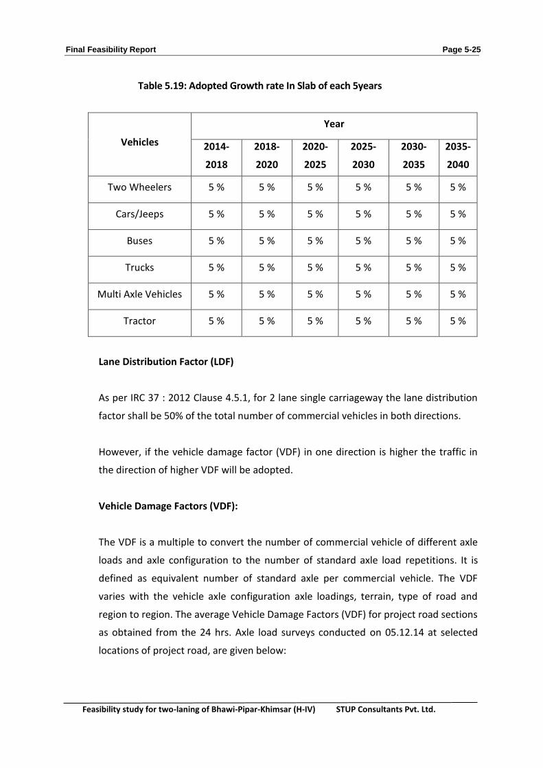
Table 5.19: Adopted Growth rate In Slab of each 5years
Vehicles
Year
2014-
2018
2018-
2020
2020-
2025
2025-
2030
2030-
2035
2035-
2040
Two Wheelers 5 % 5 % 5 % 5 % 5 % 5 %
Cars/Jeeps 5 % 5 % 5 % 5 % 5 % 5 %
Buses 5 % 5 % 5 % 5 % 5 % 5 %
Trucks 5 % 5 % 5 % 5 % 5 % 5 %
Multi Axle Vehicles 5 % 5 % 5 % 5 % 5 % 5 %
Tractor 5 % 5 % 5 % 5 % 5 % 5 %
Lane Distribution Factor (LDF)
As per IRC 37 : 2012 Clause 4.5.1, for 2 lane single carriageway the lane distribution
factor shall be 50% of the total number of commercial vehicles in both directions.
However, if the vehicle damage factor (VDF) in one direction is higher the traffic in
the direction of higher VDF will be adopted.
Vehicle Damage Factors (VDF):
The VDF is a multiple to convert the number of commercial vehicle of different axle
loads and axle configuration to the number of standard axle load repetitions. It is
defined as equivalent number of standard axle per commercial vehicle. The VDF
varies with the vehicle axle configuration axle loadings, terrain, type of road and
region to region. The average Vehicle Damage Factors (VDF) for project road sections
as obtained from the 24 hrs. Axle load surveys conducted on 05.12.14 at selected
locations of project road, are given below:
Final Feasibility Report Page 5-26
Feasibility study for two-laning of Bhawi-Pipar-Khimsar (H-IV) STUP Consultants Pvt. Ltd.
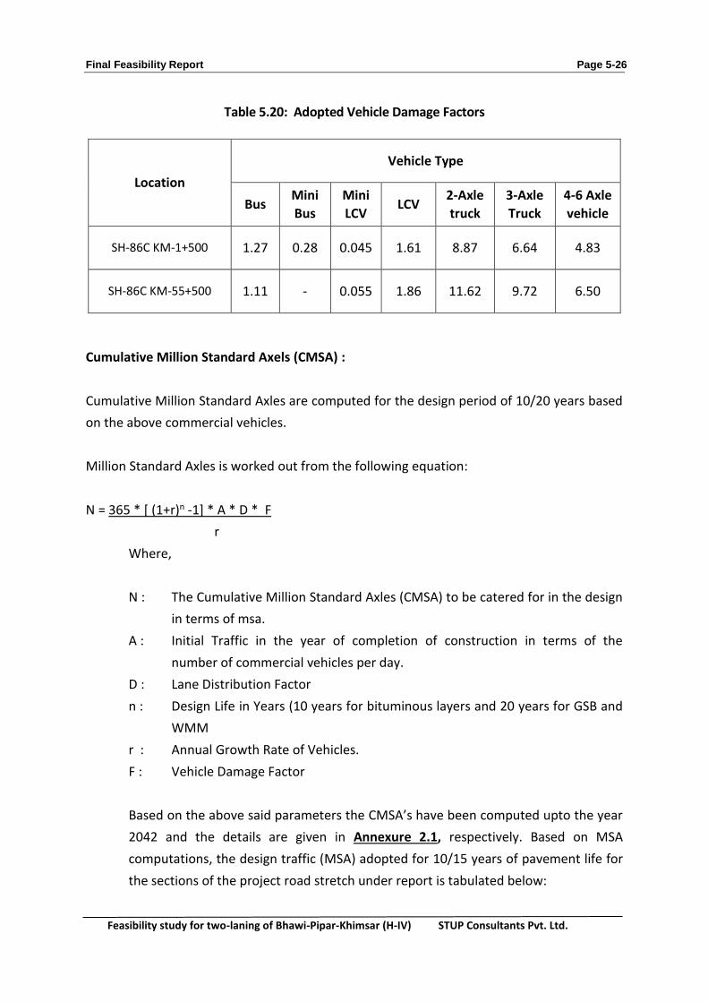
Table 5.20: Adopted Vehicle Damage Factors
Location
Vehicle Type
Bus Mini
Bus
Mini
LCV LCV
2-Axle
truck
3-Axle
Truck
4-6 Axle
vehicle
SH-86C KM-1+500 1.27 0.28 0.045 1.61 8.87 6.64 4.83
SH-86C KM-55+500 1.11 - 0.055 1.86 11.62 9.72 6.50
Cumulative Million Standard Axels (CMSA) :
Cumulative Million Standard Axles are computed for the design period of 10/20 years based
on the above commercial vehicles.
Million Standard Axles is worked out from the following equation:
N = 365 * [ (1+r)n -1] * A * D * F
r
Where,
N : The Cumulative Million Standard Axles (CMSA) to be catered for in the design
in terms of msa.
A : Initial Traffic in the year of completion of construction in terms of the
number of commercial vehicles per day.
D : Lane Distribution Factor
n : Design Life in Years (10 years for bituminous layers and 20 years for GSB and
WMM
r : Annual Growth Rate of Vehicles.
F : Vehicle Damage Factor
Based on the above said parameters the CMSA’s have been computed upto the year
2042 and the details are given in Annexure 2.1, respectively. Based on MSA
computations, the design traffic (MSA) adopted for 10/15 years of pavement life for
the sections of the project road stretch under report is tabulated below:

Final Feasibility Report Page 5-27
Feasibility study for two-laning of Bhawi-Pipar-Khimsar (H-IV) STUP Consultants Pvt. Ltd.
Table 5.21: Design Traffic for 10 / 15 Years
Homogenous Section
Km. 0.00 –Km. 31.000 Length (Km.)
10 years (Design
traffic) into MSA
15 years Design
traffic in MSA
(Km. 0 – 20) 21 0.344 0.906
Km. 31 – 55 24 10.604 17.605
Km. 55 – 71 16 8.900 14.830
Km. 75 – 89
Km. 95 - 97 18 0.488 0.813
Note: The Stretch from Km. 89-94 is Katcha Road
5.11.6 Condition of the Existing Pavement
Detailed pavement investigations including condition surveys by (a) visual inspection,
(b) examination of pavement composition by excavating test pits at regular intervals
and testing the properties of the existing subgrade soil. Its structural strength as
indicated by Benkleman Beam Deflection (BBD) was carried out to determine the
extent and nature of pavement distress of the existing carriageway. The results of
the investigations have been presented in the Chapter 4.
5.11.7 Benkelman Beam Deflection
Benkelman Beam test for the project road was conducted at selected locations to
evaluate the structural strength of the pavement. The test was carried out in
accordance with the guidelines given in IRC: 81- 1997. The Benkelman Beam
Deflection (BBD) data was analysed to determine the Characteristic Deflection of the
pavement of the project road. The detailed BBD data and it analysis for the project
road stretch under report are given in the Annexure 4.4, chapter 4 the characteristic
deflection values are found to vary from 0.3 to 1.246.
5.11.8 Homogeneous Sections
The characteristics deflection and roughness of the project road is not varying in
significant continuous length, however, the traffic volume of the road is having the
significant change in their value in four sections. Hence, the Project road is divided
into 4 Homogeneous sections based on Traffic, Roughness and BBD as following for
the Pavement Design.

Final Feasibility Report Page 5-28
Feasibility study for two-laning of Bhawi-Pipar-Khimsar (H-IV) STUP Consultants Pvt. Ltd.
Table 5.22: Homogeneous Sections
Sr.
No.
Homogeneou
s section From (km) To (km)
Length
(m)
Traffic
(msa)
1 HS-1 0.000 21.000 21 5
2 HS-2 31.000 55.000 24 10
3 HS-3 55.000 71.000 16 10
4 HS-4 75.000 89.000
22 5 95.000 97.000
5.11.9 Characteristics of the Subgrade Soil
While the design of strengthening measures will depend upon the strength and
other engineering characteristics of the subgrade soil under the existing pavement,
the new pavements will be built on and designed for the selected subgrade material
obtained from borrow areas found suitable for the purpose.
The detailed investigations of the existing subgrade soil and the borrow area
material were carried out to determine their strength (soaked CBR) and other
engineering properties. The results of these investigations for the project roads are
summarized in Table 5.23below:
Table 5.23: Engineering Characteristics of the Subgrade Soil
From To Soil Type PI
(%)
MDD
(gm/cc)
CBR (%)
(Soaked at 97%
MDD)
0 21 SM / SM-SC NP
Varies from
1.94 to 2.01
Average is 1.95
Average is 23
21 55 SM NP Average is 1.95 Average is 24
55 71 SM / SM-WG /
GM-SM NP Average is 2.01 Average is 22
75 89 SM / GM-SM NP Average is 1.96 Average is 25
95 97
SM – Silty Sand
SM – WG – Silty Sand with gravel
GM-SM - Gravel with Silty Sand
SM-SC - Clayey with Silty Sand

Final Feasibility Report Page 5-29
Feasibility study for two-laning of Bhawi-Pipar-Khimsar (H-IV) STUP Consultants Pvt. Ltd.
Table 5.24: Summary of Test Results of Borrow area Soil
Type of Test Value
Liquid Limit % NP
Plastic Limit % NP
Plasticity Index% NP
MDD gm/cc 1.94
OMC % 11.50
Soaked CBR % 24.05
5.11.10New Construction
Flexible pavements have been designed for the new construction in the widened and
bypass / realignment section.
5.11.11Design Method
IRC: 37–2012
Design Input
Design Traffic
The values of design traffic are ranging from 0.344 to 10.64 msa for 10 yrs. and 0.80
– 17.60 for 15 yrs. The adopted values are given below:
Section MSA MSA
10 Years 15 Years
HS 1 - 5 5
HS 2 - 11 20
HS 3 - 10 15
HS 4 - 5 5

Final Feasibility Report Page 5-30
Feasibility study for two-laning of Bhawi-Pipar-Khimsar (H-IV) STUP Consultants Pvt. Ltd.
Subgrade CBR
Based on the investigations of the borrow area soils identified for the construction of
new pavements, Subgrade CBR of 10 % has been adopted for the design of flexible
pavement.
5.11.12Pavement Composition
The flexible pavements for the different project roads have been designed for
service life of twenty years for sub-base / Base course and 10 years for bituminous
layers. The pavement composition details as per IRC: 37-2012 with these design
parameters are tabulated below:
Table 5.25: Composition of New Flexible Pavement
S.No. Section Traffic
(msa)
Layer Thickness (mm)
BC DBM WMM GSB Total
1 0-21 5 25 50 250 150 475
2 30-55 11 40 55 250 200 545
3 55-71 10 40 50 250 200 540
4 75-89 5 25 50 250 150 475
GSB in the widened portion will be extended up to full formation width
5.11.13Pavement Material
The general specification sections and characterization of material is presented in
Table 5.26.
Table 5.26 : Pavement Layers and Materials
S.
No. Pavement Layers and Materials
Sections Details
MoRTH
Specification
Remarks
1 Embankment Construction Section 305 Minimum Soaked CBR 8%

Final Feasibility Report Page 5-31
Feasibility study for two-laning of Bhawi-Pipar-Khimsar (H-IV) STUP Consultants Pvt. Ltd.
2 Subgrade Section 305 Minimum Soaked CBR 8%
3
Granular Sub-base
upper layer
lower layer
Section 401
Minimum compacted
thickness 150mm
Grading I of Table 400-1
Grading I of Table 400-2
4 Base Course – WMM Section 406 Thickness of single layer
shall be 75mm – 200mm
5 Prime Coat Section 502
6 Tack Coat Section 503
7 Dense Bituminous Macadam Section 505 Thickness of single layer
shall be 50mm – 100mm
8 Bituminous Concrete Section 507 Thickness of single layer
shall be 30mm – 50mm
9 Dry Lean Concrete Section 601
Thickness of single layer
shall be 100mm and
150mm
10 Pavement Quality Concrete Section 602 Minimum compacted
thickness of 140mm
5.11.14 Proposed New Pavement
Pavement thickness has been recommended for all homogeneous sections are
summarised below:
Table 5.27 : Proposed Layer of the New Pavement
S.
No. Sections (km) MSA
Layer Thickness (mm)
BC DBM WMM GSB Total
1 HS – 1 21 5 25 50 250 150 475
2 HS – 2 24 11 40 55 250 200 545
3 HS – 3 16 10 40 50 250 200 540
4 HS - 4 22 5 25 50 250 150 475
Final Feasibility Report Page 5-32
Feasibility study for two-laning of Bhawi-Pipar-Khimsar (H-IV) STUP Consultants Pvt. Ltd.
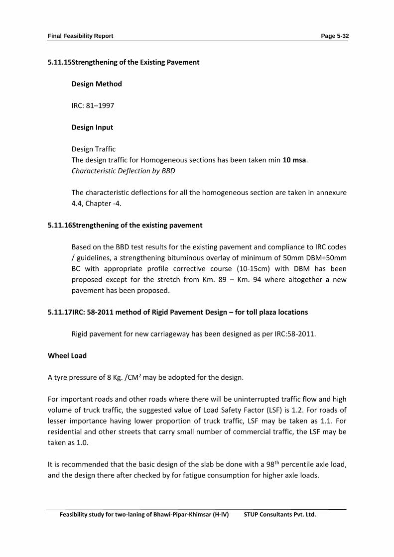
5.11.15Strengthening of the Existing Pavement
Design Method
IRC: 81–1997
Design Input
Design Traffic
The design traffic for Homogeneous sections has been taken min 10 msa.
Characteristic Deflection by BBD
The characteristic deflections for all the homogeneous section are taken in annexure
4.4, Chapter -4.
5.11.16Strengthening of the existing pavement
Based on the BBD test results for the existing pavement and compliance to IRC codes
/ guidelines, a strengthening bituminous overlay of minimum of 50mm DBM+50mm
BC with appropriate profile corrective course (10-15cm) with DBM has been
proposed except for the stretch from Km. 89 – Km. 94 where altogether a new
pavement has been proposed.
5.11.17IRC: 58-2011 method of Rigid Pavement Design – for toll plaza locations
Rigid pavement for new carriageway has been designed as per IRC:58-2011.
Wheel Load
A tyre pressure of 8 Kg. /CM2 may be adopted for the design.
For important roads and other roads where there will be uninterrupted traffic flow and high
volume of truck traffic, the suggested value of Load Safety Factor (LSF) is 1.2. For roads of
lesser importance having lower proportion of truck traffic, LSF may be taken as 1.1. For
residential and other streets that carry small number of commercial traffic, the LSF may be
taken as 1.0.
It is recommended that the basic design of the slab be done with a 98th percentile axle load,
and the design there after checked by for fatigue consumption for higher axle loads.

Final Feasibility Report Page 5-33
Feasibility study for two-laning of Bhawi-Pipar-Khimsar (H-IV) STUP Consultants Pvt. Ltd.
Design Period
Normally, cement concrete pavements have a life span of 30 years and should be designed
for this period.
Design Traffic
Design traffic of 25 per cent of the total two – lane two-way commercial vehicles may be
considered as very conservative estimate for design against fatigue failure.
Temperature Differential
Temperature differential between the top and bottom of pavements causes the concrete
slab to warp, giving rise to stresses. For this purpose, guidance may be had from table 2.13:
Table 5.28 : Recommended Temperature Differentials for Concrete
Zone States Temperatures Differentials, 0C in Slabs of
Thickness
15cm 20cm 25cm 30cm
1 Punjab, U.P., Uttarakhand, Gujarat,
Rajasthan, Haryana and North M.P.,
excluding hilly regions.
12.5 13.1 14.3 15.8
Considering all the stipulation of IRC 58-2011 the proposed rigid pavement thickness at Toll
Plaza locations is presented in Table.2.14:
Table 5.29 : Proposed Rigid Pavement Thickness at All Toll Plaza Locations
Material Type Thickness (mm)
Pavement Quality Concrete (M-40) 300
Dry Lean Concrete (M-15) 150
Granular Sub-base 150
Subgrade 500