Embed Size (px)
Citation preview
Chapter 5 Data Link Layer
Computer Networking: A Top Down Approach 6th edition Jim Kurose, Keith Ross Addison-Wesley March 2012
Network Layer 4-1
Reti degli Elaboratori Canale AL Prof.ssa Chiara Petrioli a.a. 2014/2015 We thank for the support material Prof. Kurose-Ross All material copyright 1996-2012 J.F Kurose and K.W. Ross, All Rights Reserved
5: DataLink Layer 5a-2
Chapter 5: The Data Link Layer Our goals: ❒ understand principles behind data link layer
services: ❍ error detection, correction ❍ sharing a broadcast channel: multiple access ❍ link layer addressing ❍ reliable data transfer, flow control: done!
❒ instantiation and implementation of various link layer technologies
5: DataLink Layer 5a-3
Link Layer
❒ 5.1 Introduction and services
❒ 5.2 Error detection and correction
❒ 5.3Multiple access protocols
❒ 5.4 Link-layer Addressing
❒ 5.5 Ethernet
❒ 5.6 Link-layer switches ❒ 5.7 PPP ❒ 5.8 Link virtualization:
MPLS ❒ 5.9 A day in the life of a
web request
5: DataLink Layer 5a-4
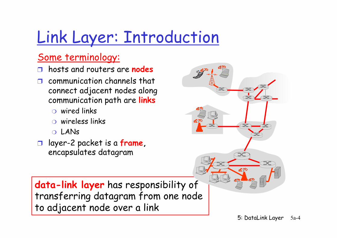
Link Layer: Introduction Some terminology: ❒ hosts and routers are nodes ❒ communication channels that
connect adjacent nodes along communication path are links ❍ wired links ❍ wireless links ❍ LANs
❒ layer-2 packet is a frame, encapsulates datagram
data-link layer has responsibility of transferring datagram from one node to adjacent node over a link
5: DataLink Layer 5a-5
Link layer: context ❒ datagram transferred by
different link protocols over different links: ❍ e.g., Ethernet on first link,
frame relay on intermediate links, 802.11 on last link
❒ each link protocol provides different services ❍ e.g., may or may not
provide rdt over link
transportation analogy ❒ trip from Princeton to
Lausanne ❍ limo: Princeton to JFK ❍ plane: JFK to Geneva ❍ train: Geneva to Lausanne
❒ tourist = datagram ❒ transport segment =
communication link ❒ transportation mode = link
layer protocol ❒ travel agent = routing
algorithm
5: DataLink Layer 5a-6
Link Layer Services
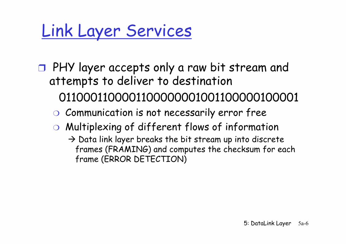
❒ PHY layer accepts only a raw bit stream and attempts to deliver to destination
0110001100001100000001001100000100001 ❍ Communication is not necessarily error free ❍ Multiplexing of different flows of information
à Data link layer breaks the bit stream up into discrete frames (FRAMING) and computes the checksum for each frame (ERROR DETECTION)
5: DataLink Layer 5a-7
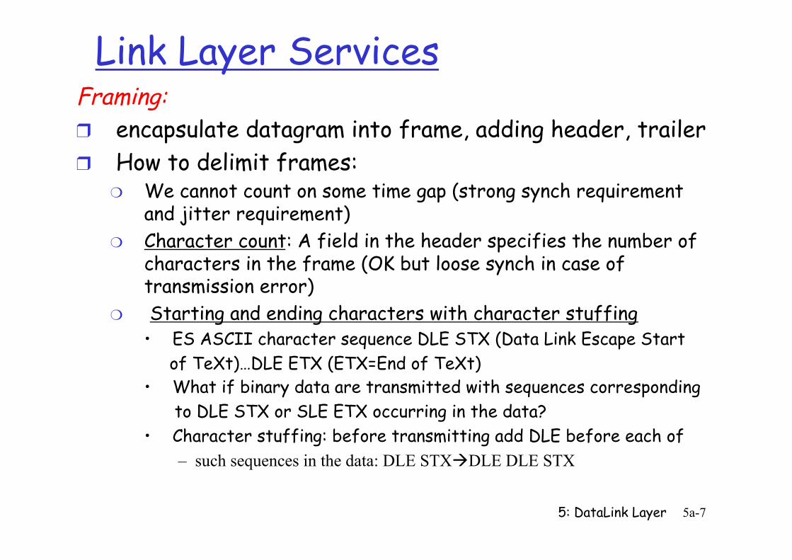
Link Layer Services Framing: ❒ encapsulate datagram into frame, adding header, trailer ❒ How to delimit frames:
❍ We cannot count on some time gap (strong synch requirement and jitter requirement)
❍ Character count: A field in the header specifies the number of characters in the frame (OK but loose synch in case of transmission error)
❍ Starting and ending characters with character stuffing • ES ASCII character sequence DLE STX (Data Link Escape Start of TeXt)…DLE ETX (ETX=End of TeXt) • What if binary data are transmitted with sequences corresponding to DLE STX or SLE ETX occurring in the data? • Character stuffing: before transmitting add DLE before each of
– such sequences in the data: DLE STXàDLE DLE STX
5: DataLink Layer 5a-8
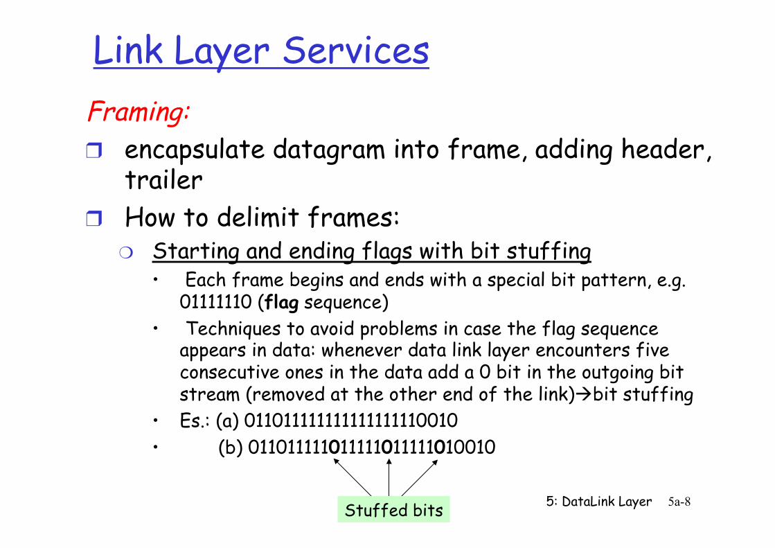
Link Layer Services Framing: ❒ encapsulate datagram into frame, adding header,
trailer ❒ How to delimit frames:
❍ Starting and ending flags with bit stuffing • Each frame begins and ends with a special bit pattern, e.g.
01111110 (flag sequence) • Techniques to avoid problems in case the flag sequence
appears in data: whenever data link layer encounters five consecutive ones in the data add a 0 bit in the outgoing bit stream (removed at the other end of the link)àbit stuffing
• Es.: (a) 011011111111111111110010 • (b) 011011111011111011111010010
Stuffed bits
5: DataLink Layer 5a-9
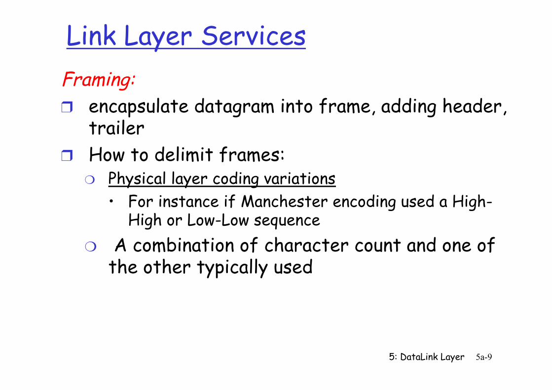
Link Layer Services Framing: ❒ encapsulate datagram into frame, adding header,
trailer ❒ How to delimit frames:
❍ Physical layer coding variations • For instance if Manchester encoding used a High-
High or Low-Low sequence ❍ A combination of character count and one of
the other typically used
5: DataLink Layer 5-10
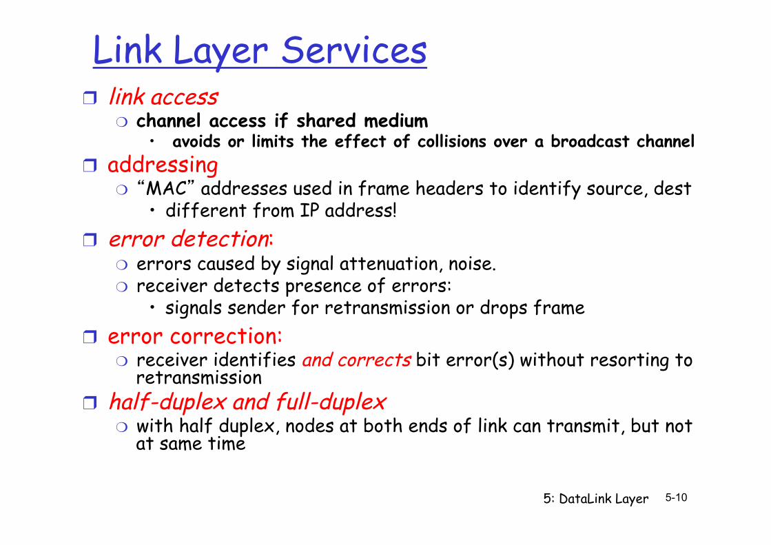
Link Layer Services ❒ link access
❍ channel access if shared medium • avoids or limits the effect of collisions over a broadcast channel
❒ addressing ❍ “MAC” addresses used in frame headers to identify source, dest
• different from IP address! ❒ error detection:
❍ errors caused by signal attenuation, noise. ❍ receiver detects presence of errors:
• signals sender for retransmission or drops frame ❒ error correction:
❍ receiver identifies and corrects bit error(s) without resorting to retransmission
❒ half-duplex and full-duplex ❍ with half duplex, nodes at both ends of link can transmit, but not
at same time
5: DataLink Layer 5a-11
Link Layer Services (more)
❒ reliable delivery between adjacent nodes ❍ we learned how to do this already (chapter 3)! ❍ seldom used on low bit-error link (fiber, some
twisted pair) ❍ wireless links: high error rates
• Q: why both link-level and end-end reliability?
❒ flow control: ❍ pacing between adjacent sending and receiving
nodes
5: DataLink Layer 5a-12
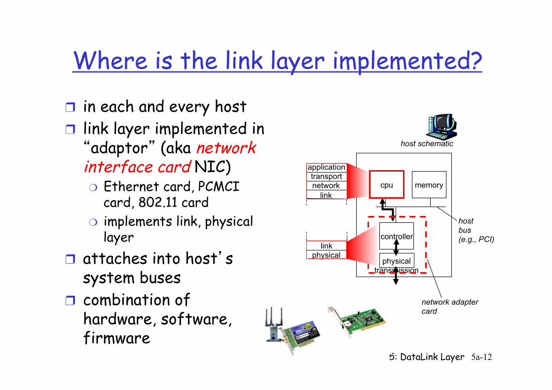
Where is the link layer implemented?
❒ in each and every host ❒ link layer implemented in “adaptor” (aka network interface card NIC) ❍ Ethernet card, PCMCI
card, 802.11 card ❍ implements link, physical
layer ❒ attaches into host’s
system buses ❒ combination of
hardware, software, firmware
controller
physical transmission
cpu memory
host bus (e.g., PCI)
network adapter card
host schematic
application transport network
link
link physical
5: DataLink Layer 5a-13
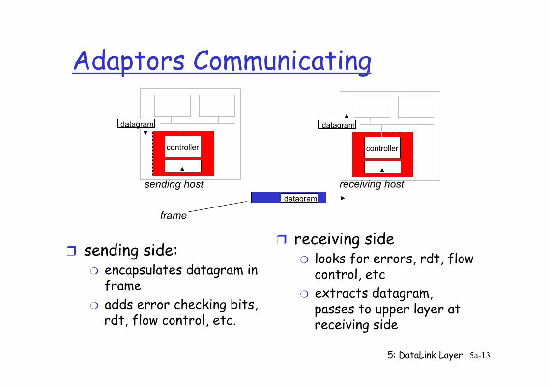
Adaptors Communicating
❒ sending side: ❍ encapsulates datagram in
frame ❍ adds error checking bits,
rdt, flow control, etc.
❒ receiving side ❍ looks for errors, rdt, flow
control, etc ❍ extracts datagram,
passes to upper layer at receiving side
controller controller
sending host receiving host
datagram datagram
datagram
frame
5: DataLink Layer 5a-14
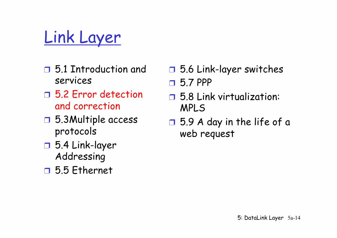
Link Layer
❒ 5.1 Introduction and services
❒ 5.2 Error detection and correction
❒ 5.3Multiple access protocols
❒ 5.4 Link-layer Addressing
❒ 5.5 Ethernet
❒ 5.6 Link-layer switches ❒ 5.7 PPP ❒ 5.8 Link virtualization:
MPLS ❒ 5.9 A day in the life of a
web request
5: DataLink Layer 5a-15
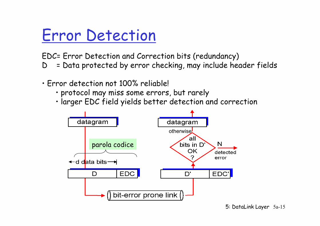
Error Detection EDC= Error Detection and Correction bits (redundancy) D = Data protected by error checking, may include header fields • Error detection not 100% reliable!
• protocol may miss some errors, but rarely • larger EDC field yields better detection and correction
otherwise
parola codice
5: DataLink Layer 5a-16
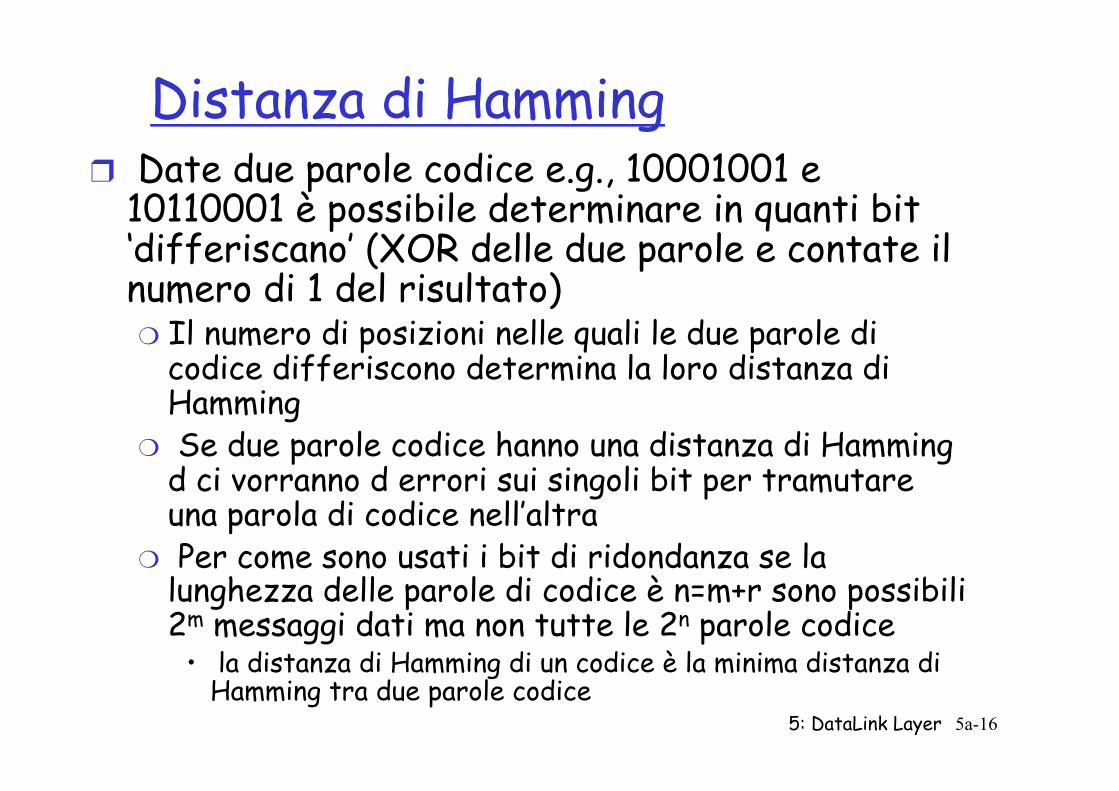
Distanza di Hamming ❒ Date due parole codice e.g., 10001001 e
10110001 è possibile determinare in quanti bit ‘differiscano’ (XOR delle due parole e contate il numero di 1 del risultato) ❍ Il numero di posizioni nelle quali le due parole di
codice differiscono determina la loro distanza di Hamming
❍ Se due parole codice hanno una distanza di Hamming d ci vorranno d errori sui singoli bit per tramutare una parola di codice nell’altra
❍ Per come sono usati i bit di ridondanza se la lunghezza delle parole di codice è n=m+r sono possibili 2m messaggi dati ma non tutte le 2n parole codice
• la distanza di Hamming di un codice è la minima distanza di Hamming tra due parole codice
5: DataLink Layer 5a-17
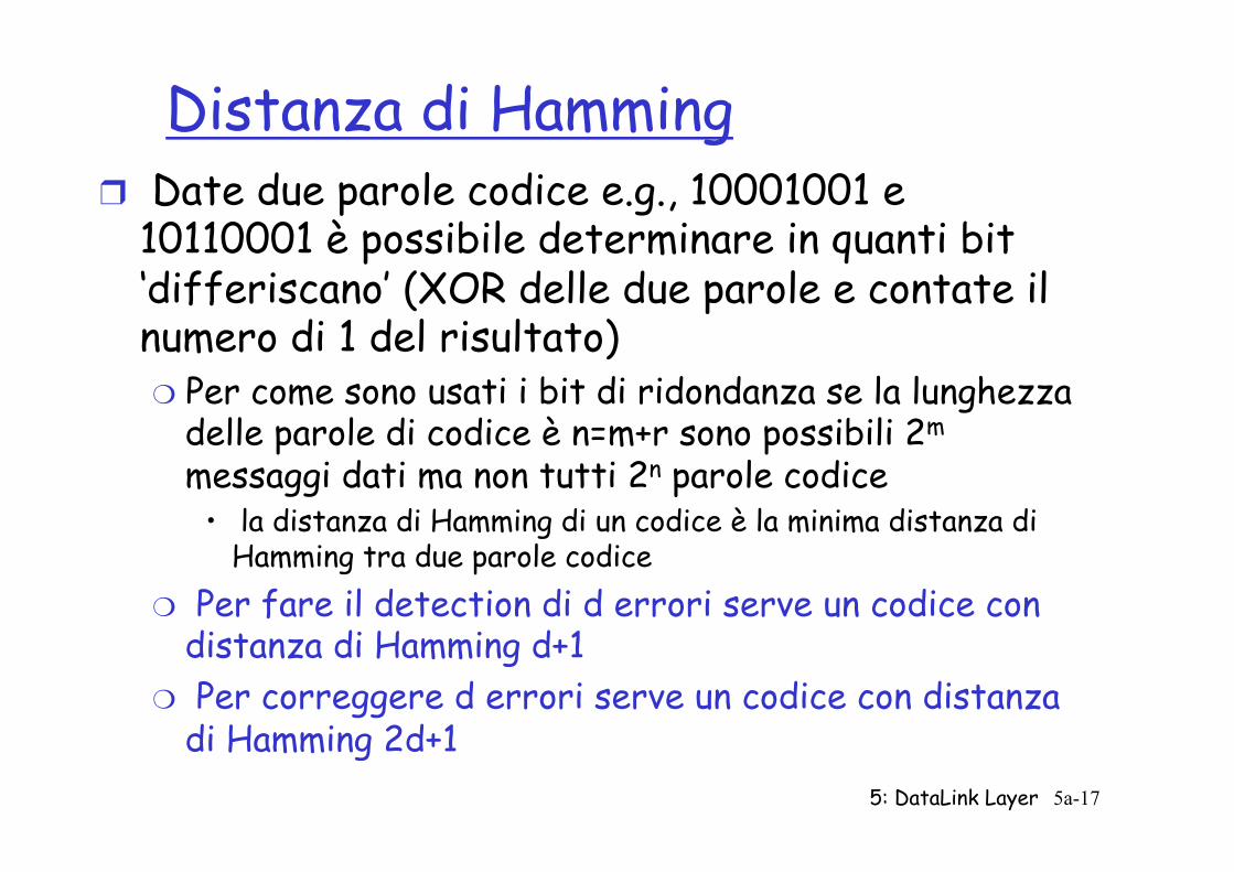
Distanza di Hamming ❒ Date due parole codice e.g., 10001001 e
10110001 è possibile determinare in quanti bit ‘differiscano’ (XOR delle due parole e contate il numero di 1 del risultato) ❍ Per come sono usati i bit di ridondanza se la lunghezza
delle parole di codice è n=m+r sono possibili 2m messaggi dati ma non tutti 2n parole codice
• la distanza di Hamming di un codice è la minima distanza di Hamming tra due parole codice
❍ Per fare il detection di d errori serve un codice con distanza di Hamming d+1
❍ Per correggere d errori serve un codice con distanza di Hamming 2d+1
5: DataLink Layer 5a-18
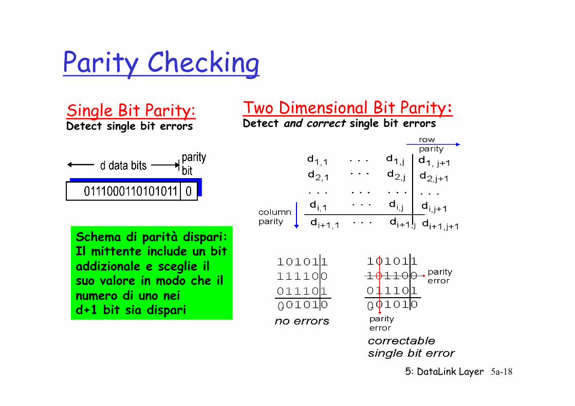
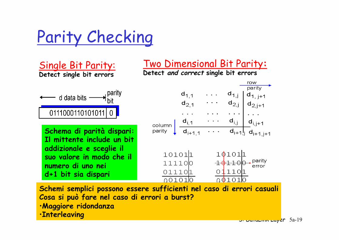
Parity Checking Single Bit Parity: Detect single bit errors
Two Dimensional Bit Parity: Detect and correct single bit errors
0 0
Schema di parità dispari: Il mittente include un bit addizionale e sceglie il suo valore in modo che il numero di uno nei d+1 bit sia dispari
5: DataLink Layer 5a-19
Parity Checking Single Bit Parity: Detect single bit errors
Two Dimensional Bit Parity: Detect and correct single bit errors
0 0
Schema di parità dispari: Il mittente include un bit addizionale e sceglie il suo valore in modo che il numero di uno nei d+1 bit sia dispari
Schemi semplici possono essere sufficienti nel caso di errori casuali Cosa si può fare nel caso di errori a burst? • Maggiore ridondanza • Interleaving
5: DataLink Layer 5a-20
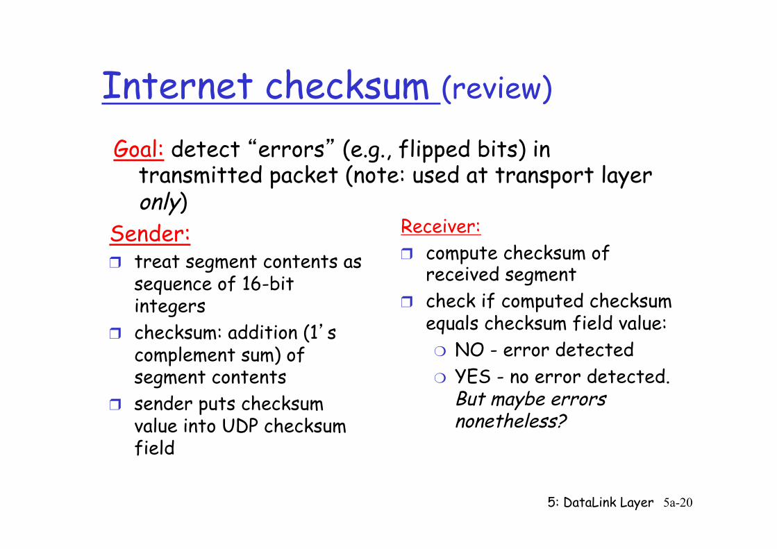
Internet checksum (review)
Sender: ❒ treat segment contents as
sequence of 16-bit integers
❒ checksum: addition (1’s complement sum) of segment contents
❒ sender puts checksum value into UDP checksum field
Receiver: ❒ compute checksum of
received segment ❒ check if computed checksum
equals checksum field value: ❍ NO - error detected ❍ YES - no error detected.
But maybe errors nonetheless?
Goal: detect “errors” (e.g., flipped bits) in transmitted packet (note: used at transport layer only)
5: DataLink Layer 5a-21
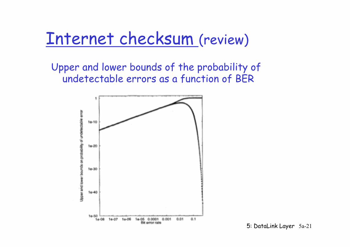
Internet checksum (review)
Upper and lower bounds of the probability of undetectable errors as a function of BER
5: DataLink Layer 5a-22
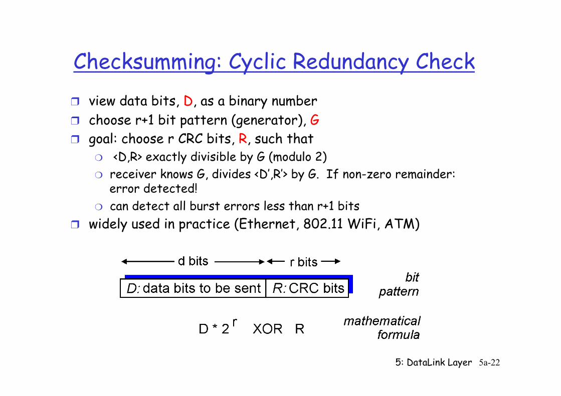
Checksumming: Cyclic Redundancy Check ❒ view data bits, D, as a binary number ❒ choose r+1 bit pattern (generator), G ❒ goal: choose r CRC bits, R, such that
❍ <D,R> exactly divisible by G (modulo 2) ❍ receiver knows G, divides <D’,R’> by G. If non-zero remainder:
error detected! ❍ can detect all burst errors less than r+1 bits
❒ widely used in practice (Ethernet, 802.11 WiFi, ATM)
5: DataLink Layer 5a-23
CRC
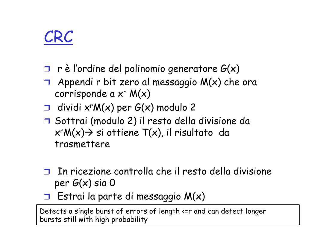
❒ r è l’ordine del polinomio generatore G(x) ❒ Appendi r bit zero al messaggio M(x) che ora
corrisponde a xr M(x) ❒ dividi xrM(x) per G(x) modulo 2 ❒ Sottrai (modulo 2) il resto della divisione da
xrM(x)à si ottiene T(x), il risultato da trasmettere
❒ In ricezione controlla che il resto della divisione per G(x) sia 0
❒ Estrai la parte di messaggio M(x) Detects a single burst of errors of length <=r and can detect longer bursts still with high probability
5: DataLink Layer 5a-24
Link Layer
❒ 5.1 Introduction and services
❒ 5.2 Error detection and correction
❒ 5.3Multiple access protocols
❒ 5.4 Link-layer Addressing
❒ 5.5 Ethernet
❒ 5.6 Link-layer switches ❒ 5.7 PPP ❒ 5.8 Link virtualization:
MPLS ❒ 5.9 A day in the life of a
web request
5: DataLink Layer 5a-25
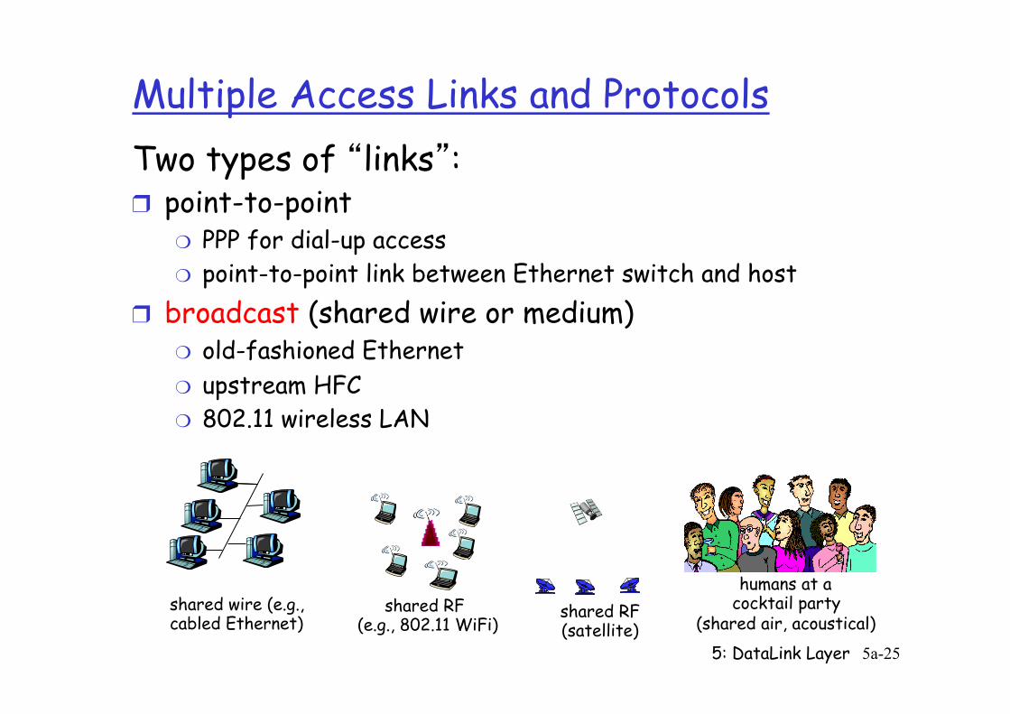
Multiple Access Links and Protocols Two types of “links”: ❒ point-to-point
❍ PPP for dial-up access ❍ point-to-point link between Ethernet switch and host
❒ broadcast (shared wire or medium) ❍ old-fashioned Ethernet ❍ upstream HFC ❍ 802.11 wireless LAN
shared wire (e.g., cabled Ethernet)
shared RF (e.g., 802.11 WiFi)
shared RF (satellite)
humans at a cocktail party
(shared air, acoustical)
5: DataLink Layer 5a-26
Multiple Access protocols ❒ single shared broadcast channel ❒ two or more simultaneous transmissions by nodes:
interference ❍ collision if node receives two or more signals at the same time
multiple access protocol ❒ distributed algorithm that determines how nodes
share channel, i.e., determine when node can transmit ❒ communication about channel sharing must use channel
itself! ❍ no out-of-band channel for coordination
5: DataLink Layer 5a-27
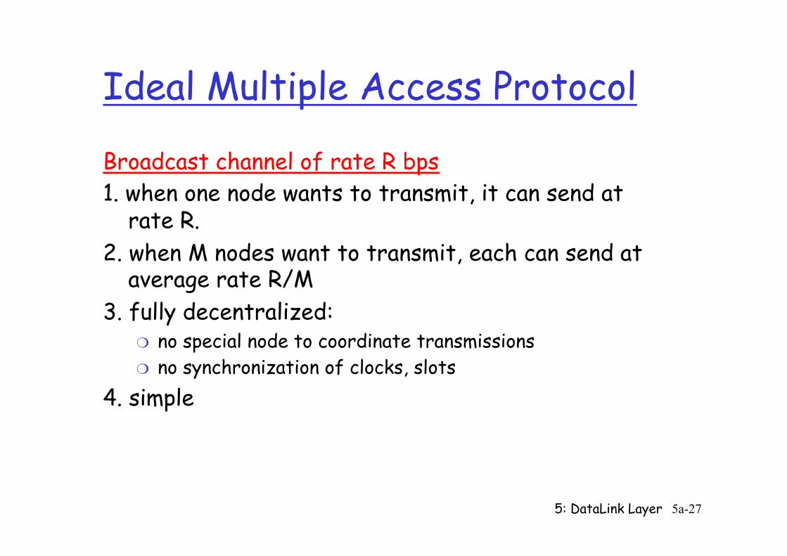
Ideal Multiple Access Protocol
Broadcast channel of rate R bps 1. when one node wants to transmit, it can send at
rate R. 2. when M nodes want to transmit, each can send at
average rate R/M 3. fully decentralized:
❍ no special node to coordinate transmissions ❍ no synchronization of clocks, slots
4. simple
5: DataLink Layer 5a-28
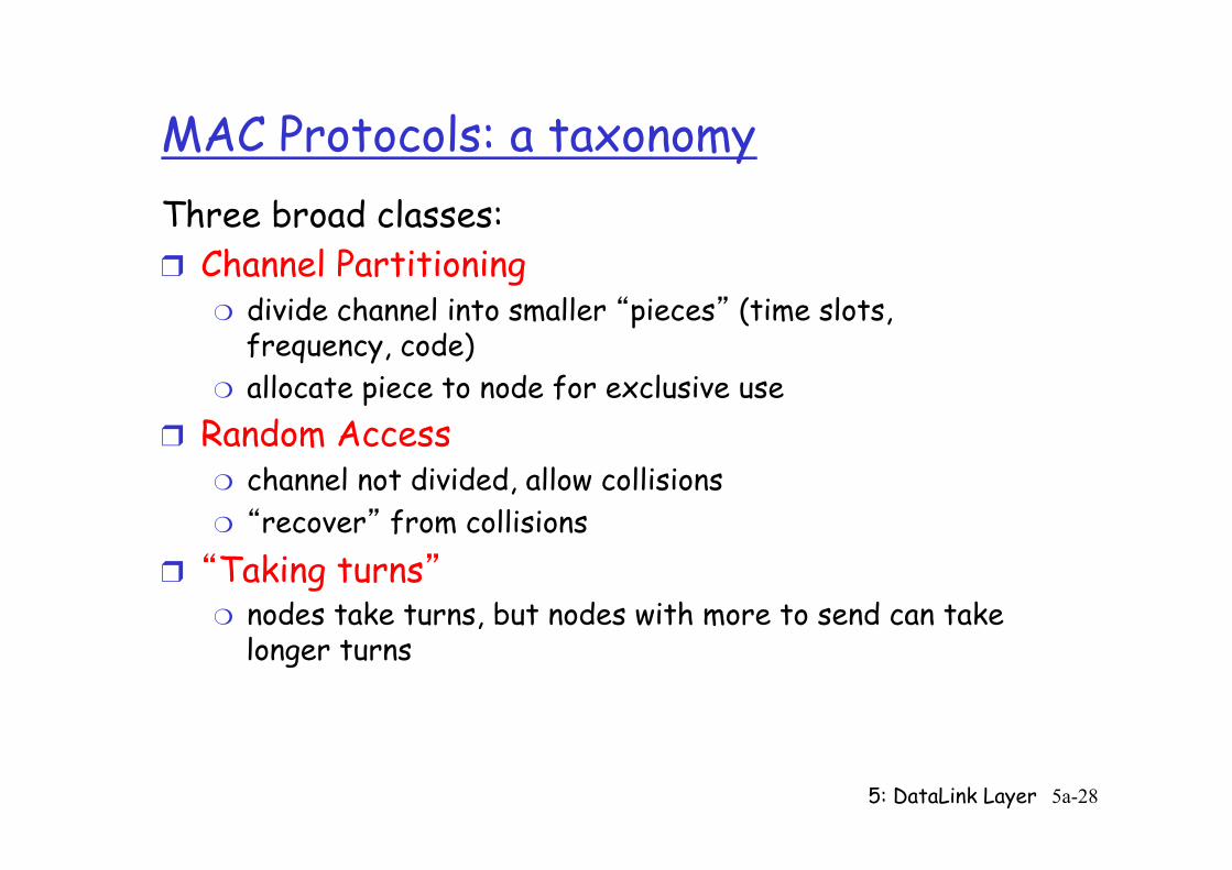
MAC Protocols: a taxonomy Three broad classes: ❒ Channel Partitioning
❍ divide channel into smaller “pieces” (time slots, frequency, code)
❍ allocate piece to node for exclusive use ❒ Random Access
❍ channel not divided, allow collisions ❍ “recover” from collisions
❒ “Taking turns” ❍ nodes take turns, but nodes with more to send can take
longer turns
5: DataLink Layer 5a-29
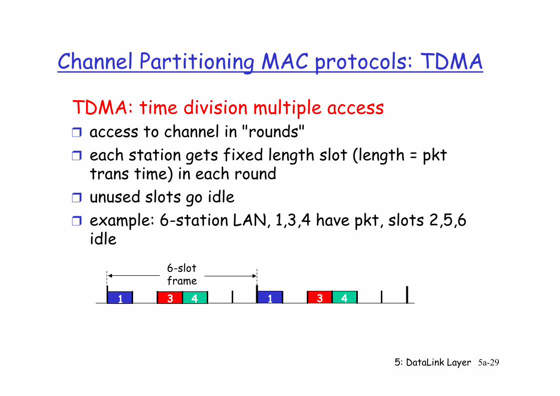
Channel Partitioning MAC protocols: TDMA TDMA: time division multiple access ❒ access to channel in "rounds" ❒ each station gets fixed length slot (length = pkt
trans time) in each round ❒ unused slots go idle ❒ example: 6-station LAN, 1,3,4 have pkt, slots 2,5,6
idle
1 3 4 1 3 4
6-slot frame
5: DataLink Layer 5a-30
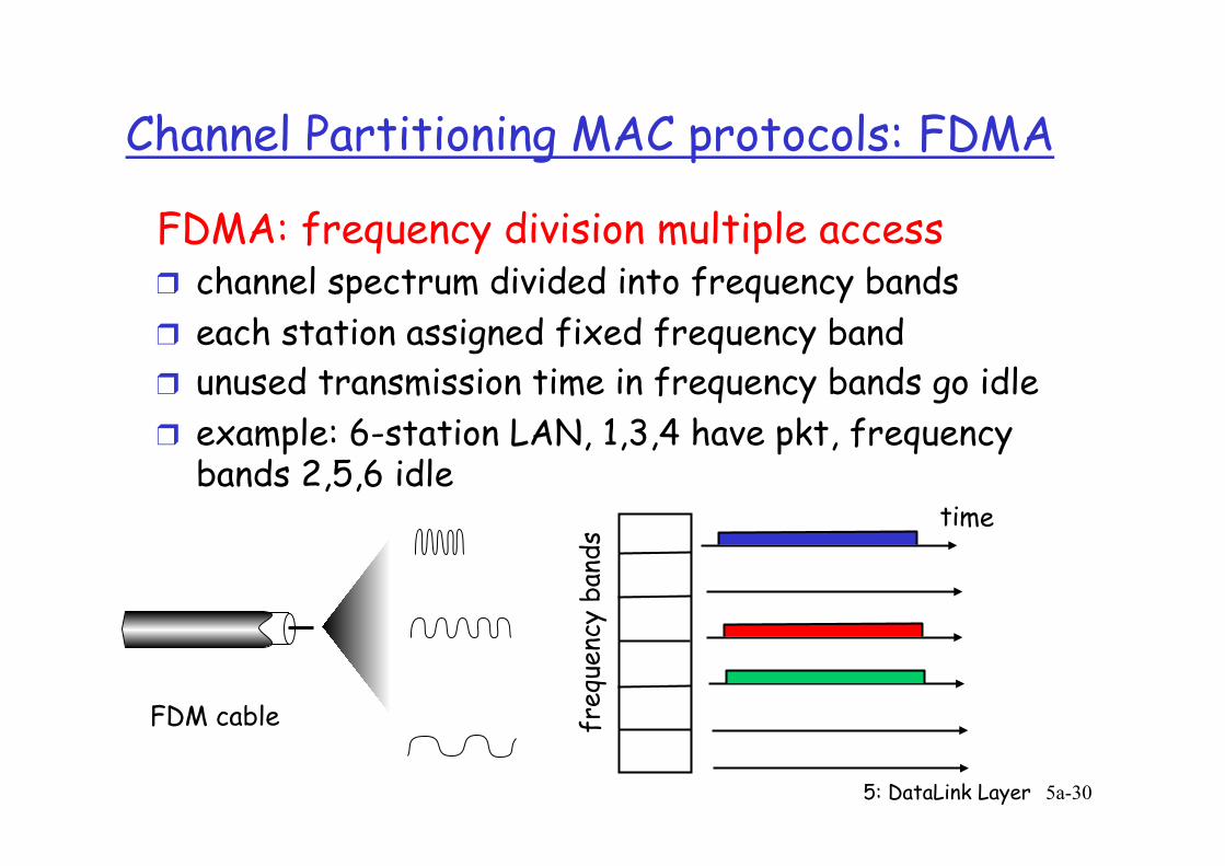
Channel Partitioning MAC protocols: FDMA FDMA: frequency division multiple access ❒ channel spectrum divided into frequency bands ❒ each station assigned fixed frequency band ❒ unused transmission time in frequency bands go idle ❒ example: 6-station LAN, 1,3,4 have pkt, frequency
bands 2,5,6 idle
freq
uenc
y ba
nds
time
FDM cable
5: DataLink Layer 5a-31
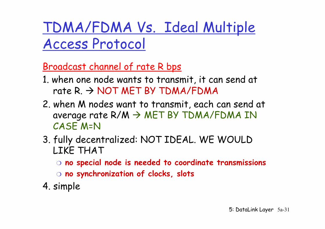
TDMA/FDMA Vs. Ideal Multiple Access Protocol Broadcast channel of rate R bps 1. when one node wants to transmit, it can send at
rate R. à NOT MET BY TDMA/FDMA 2. when M nodes want to transmit, each can send at
average rate R/M à MET BY TDMA/FDMA IN CASE M=N
3. fully decentralized: NOT IDEAL. WE WOULD LIKE THAT ❍ no special node is needed to coordinate transmissions ❍ no synchronization of clocks, slots
4. simple
5: DataLink Layer 5a-32
Slotted ALOHA
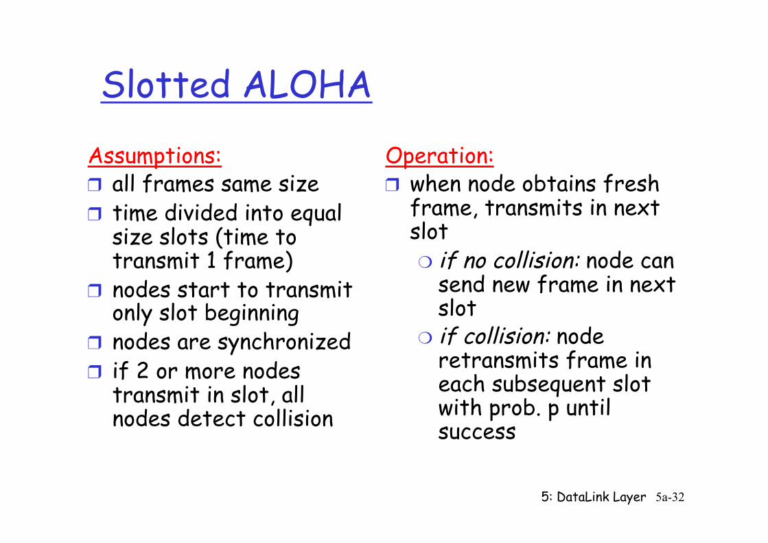
Assumptions: ❒ all frames same size ❒ time divided into equal
size slots (time to transmit 1 frame)
❒ nodes start to transmit only slot beginning
❒ nodes are synchronized ❒ if 2 or more nodes
transmit in slot, all nodes detect collision
Operation: ❒ when node obtains fresh
frame, transmits in next slot ❍ if no collision: node can
send new frame in next slot
❍ if collision: node retransmits frame in each subsequent slot with prob. p until success
5: DataLink Layer 5a-33
Slotted ALOHA
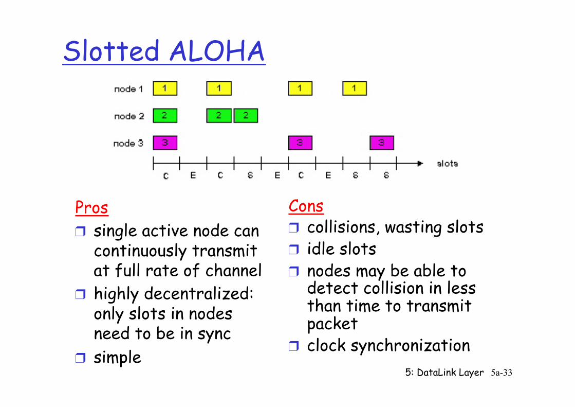
Pros ❒ single active node can
continuously transmit at full rate of channel
❒ highly decentralized: only slots in nodes need to be in sync
❒ simple
Cons ❒ collisions, wasting slots ❒ idle slots ❒ nodes may be able to
detect collision in less than time to transmit packet
❒ clock synchronization
5: DataLink Layer 5a-34
Slotted Aloha efficiency
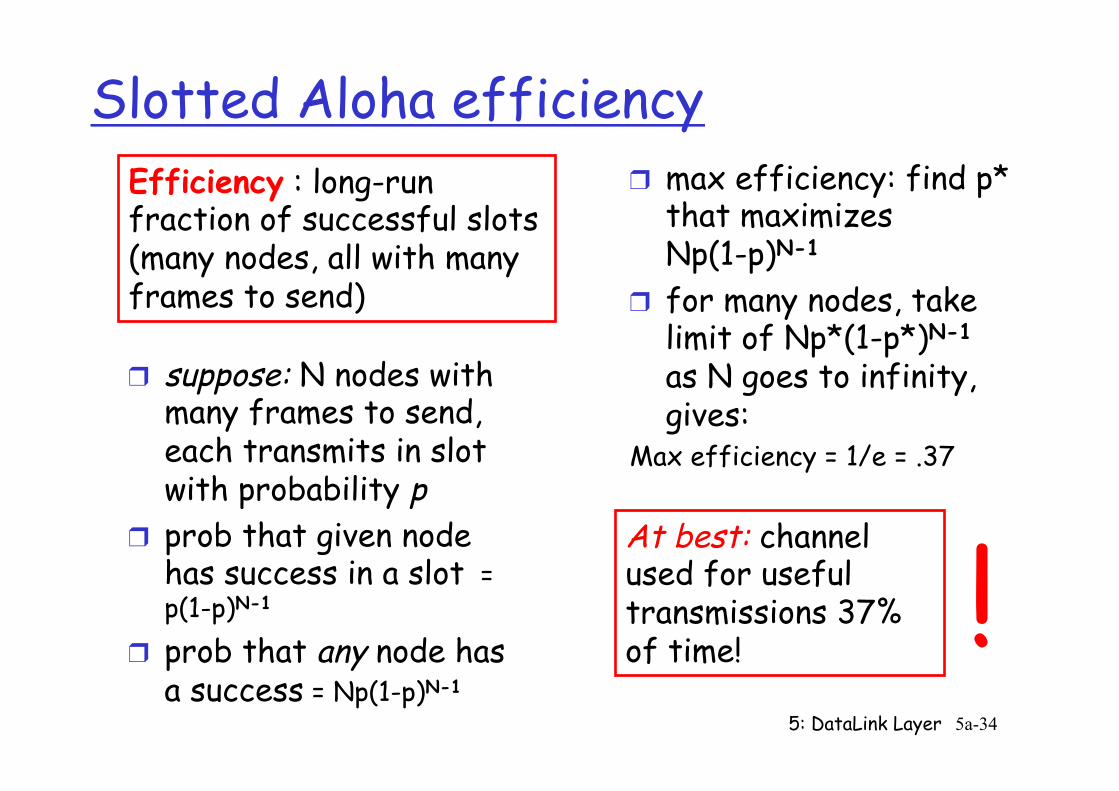
❒ suppose: N nodes with many frames to send, each transmits in slot with probability p
❒ prob that given node has success in a slot = p(1-p)N-1
❒ prob that any node has a success = Np(1-p)N-1
❒ max efficiency: find p* that maximizes Np(1-p)N-1
❒ for many nodes, take limit of Np*(1-p*)N-1
as N goes to infinity, gives:
Max efficiency = 1/e = .37
Efficiency : long-run fraction of successful slots (many nodes, all with many frames to send)
At best: channel used for useful transmissions 37% of time! !
5: DataLink Layer 5a-35
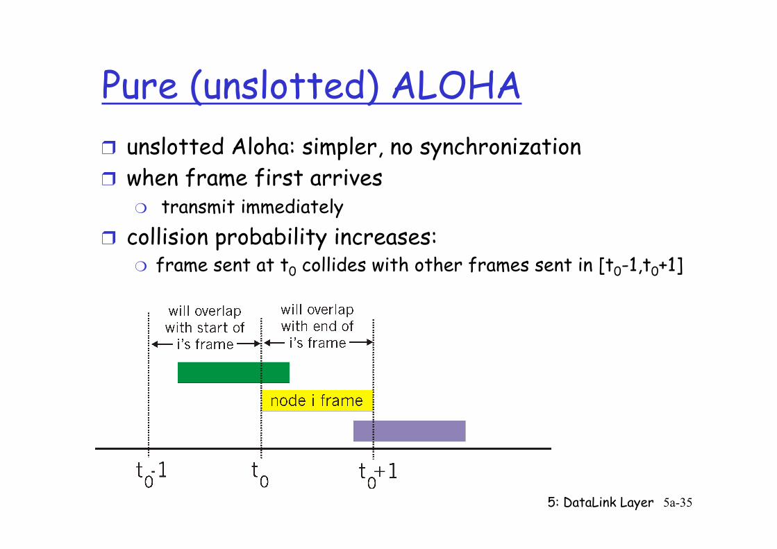
Pure (unslotted) ALOHA ❒ unslotted Aloha: simpler, no synchronization ❒ when frame first arrives
❍ transmit immediately ❒ collision probability increases:
❍ frame sent at t0 collides with other frames sent in [t0-1,t0+1]
5: DataLink Layer 5a-36
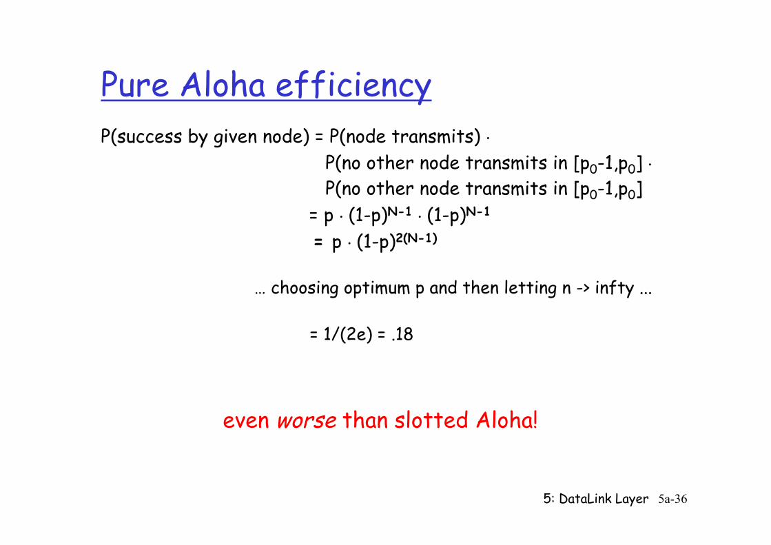
Pure Aloha efficiency P(success by given node) = P(node transmits) . P(no other node transmits in [p0-1,p0] . P(no other node transmits in [p0-1,p0] = p . (1-p)N-1 . (1-p)N-1
= p . (1-p)2(N-1) … choosing optimum p and then letting n -> infty ...
= 1/(2e) = .18
even worse than slotted Aloha!
5: DataLink Layer 5a-37
CSMA (Carrier Sense Multiple Access)
CSMA: listen before transmit: If channel sensed idle: transmit entire frame ❒ If channel sensed busy, defer transmission
❒ human analogy: don’t interrupt others!
5: DataLink Layer 5a-38
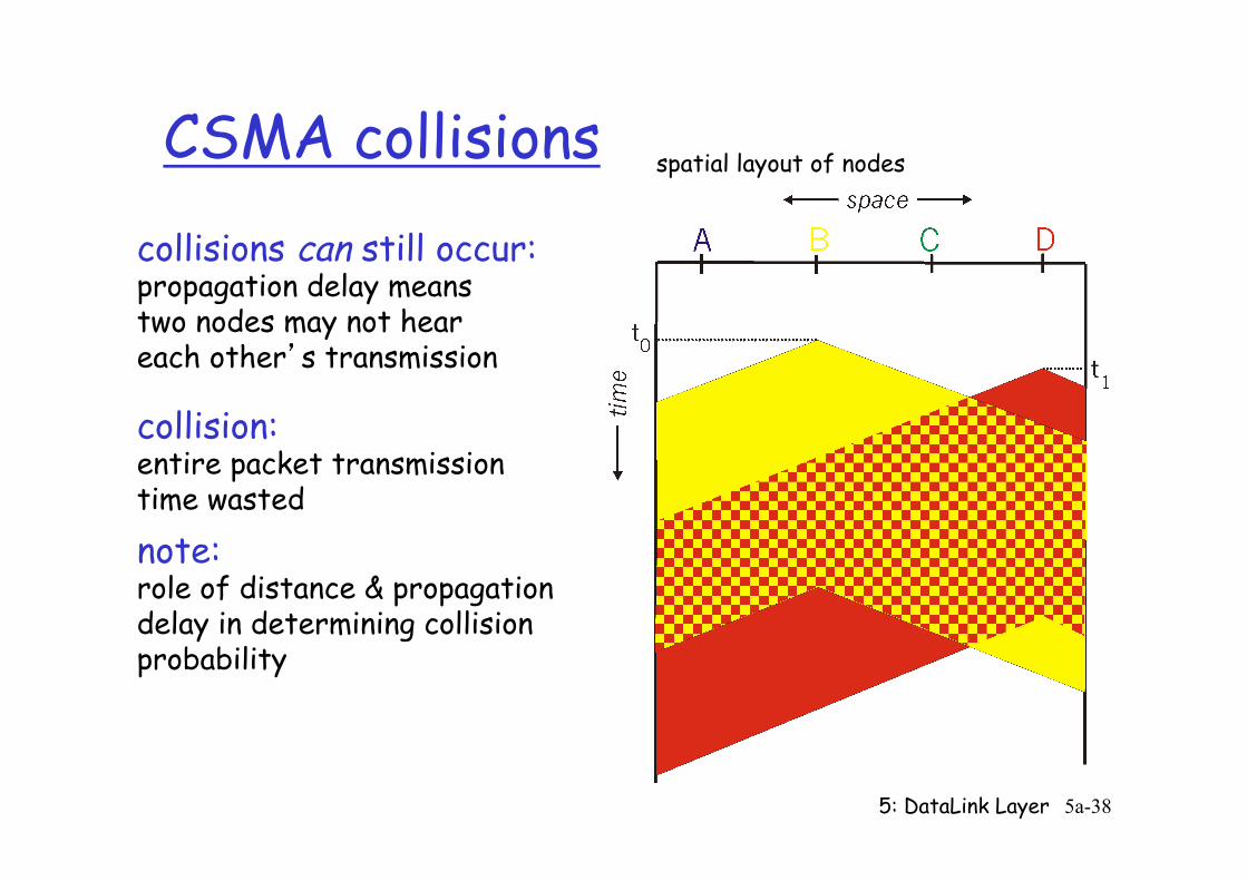
CSMA collisions collisions can still occur: propagation delay means two nodes may not hear each other’s transmission
collision: entire packet transmission time wasted
spatial layout of nodes
note: role of distance & propagation delay in determining collision probability
5: DataLink Layer 5a-39
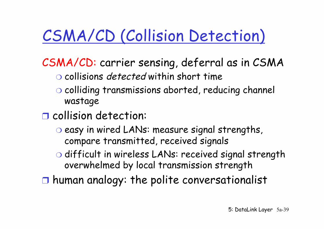
CSMA/CD (Collision Detection) CSMA/CD: carrier sensing, deferral as in CSMA
❍ collisions detected within short time ❍ colliding transmissions aborted, reducing channel
wastage ❒ collision detection:
❍ easy in wired LANs: measure signal strengths, compare transmitted, received signals
❍ difficult in wireless LANs: received signal strength overwhelmed by local transmission strength
❒ human analogy: the polite conversationalist
5: DataLink Layer 5a-40
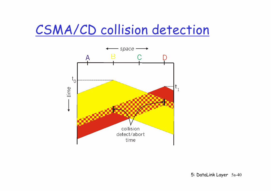
CSMA/CD collision detection
5: DataLink Layer 5a-41
“Taking Turns” MAC protocols
channel partitioning MAC protocols: ❍ share channel efficiently and fairly at high load ❍ inefficient at low load: delay in channel access,
1/N bandwidth allocated even if only 1 active node!
Random access MAC protocols ❍ efficient at low load: single node can fully
utilize channel ❍ high load: collision overhead
“taking turns” protocols look for best of both worlds!
5: DataLink Layer 5a-42
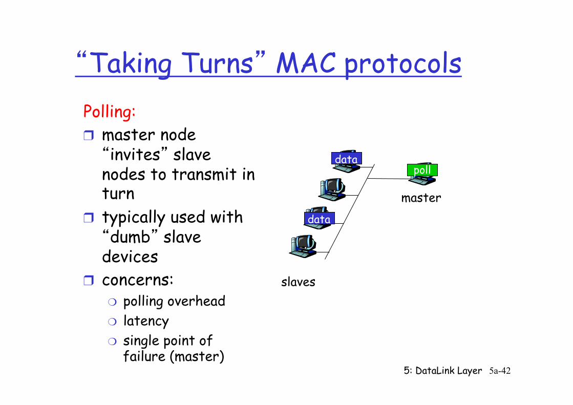
“Taking Turns” MAC protocols Polling: ❒ master node “invites” slave nodes to transmit in turn
❒ typically used with “dumb” slave devices
❒ concerns: ❍ polling overhead ❍ latency ❍ single point of
failure (master)
master
slaves
poll
data
data
5: DataLink Layer 5a-43
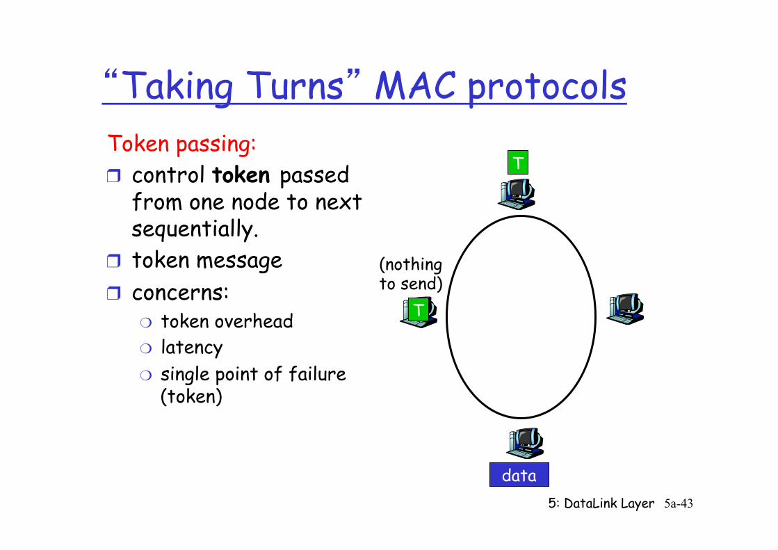
“Taking Turns” MAC protocols Token passing: ❒ control token passed
from one node to next sequentially.
❒ token message ❒ concerns:
❍ token overhead ❍ latency ❍ single point of failure
(token)
T
data
(nothing to send)
T
5: DataLink Layer 5a-44
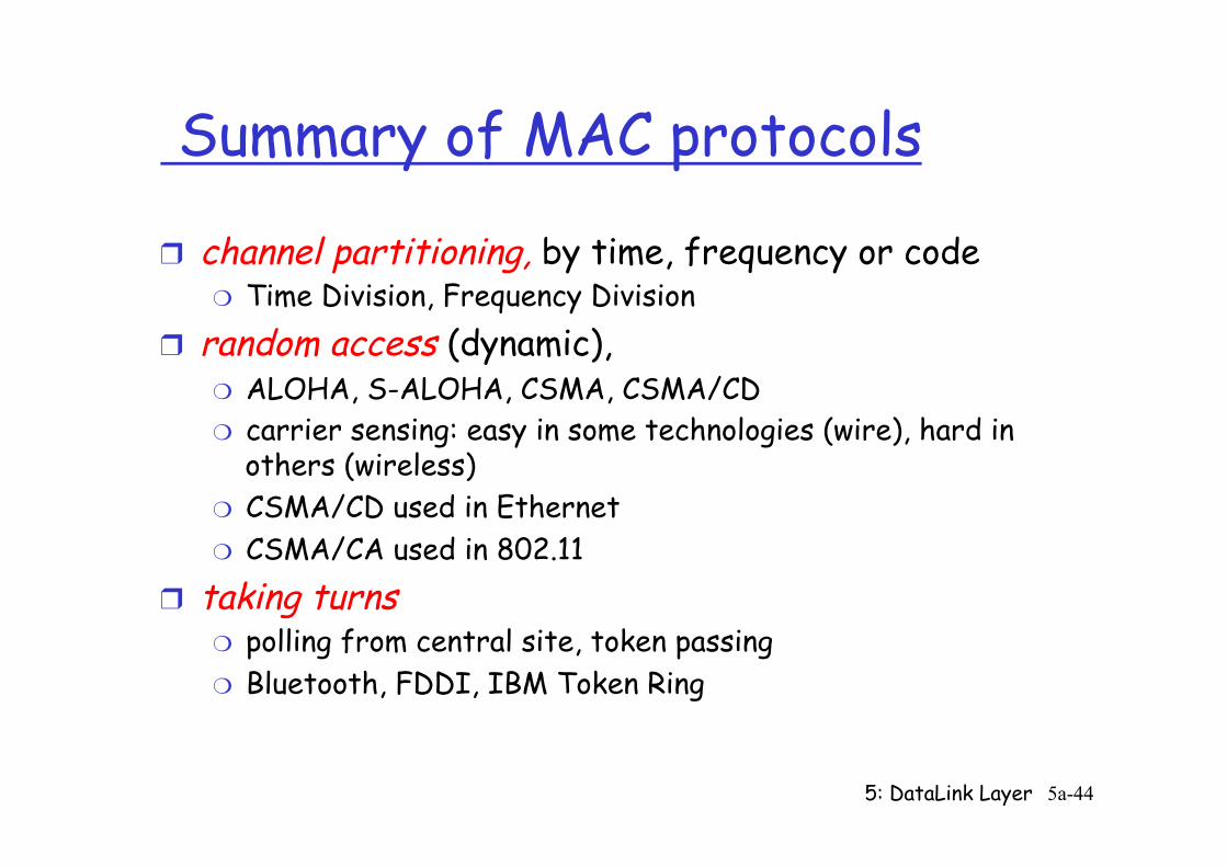
Summary of MAC protocols
❒ channel partitioning, by time, frequency or code ❍ Time Division, Frequency Division
❒ random access (dynamic), ❍ ALOHA, S-ALOHA, CSMA, CSMA/CD ❍ carrier sensing: easy in some technologies (wire), hard in
others (wireless) ❍ CSMA/CD used in Ethernet ❍ CSMA/CA used in 802.11
❒ taking turns ❍ polling from central site, token passing ❍ Bluetooth, FDDI, IBM Token Ring
5: DataLink Layer 5a-45
LAN Addresses and ARP
32-bit IP address: ❒ network-layer address ❒ used to get datagram to destination IP network
(recall IP network definition) LAN (or MAC or physical or Ethernet) address: ❒ used to get datagram from one interface to another
physically-connected interface (same network) ❒ 48 bit MAC address (for most LANs)
burned in the adapter ROM
5: DataLink Layer 5a-46
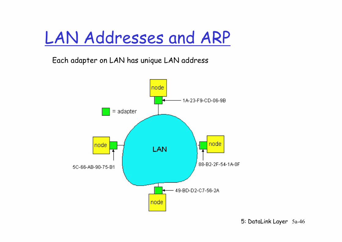
LAN Addresses and ARP Each adapter on LAN has unique LAN address
5: DataLink Layer 5a-47
LAN Address (more)
❒ MAC address allocation administered by IEEE ❒ manufacturer buys portion of MAC address space
(to assure uniqueness) ❒ Analogy: (a) MAC address: like Social Security Number (b) IP address: like postal address ❒ MAC flat address => portability
❍ can move LAN card from one LAN to another ❒ IP hierarchical address NOT portable
❍ depends on IP network to which node is attached
5: DataLink Layer 5a-48
Recall earlier routing discussion
223.1.1.1
223.1.1.2
223.1.1.3
223.1.1.4 223.1.2.9
223.1.2.2
223.1.2.1
223.1.3.2 223.1.3.1
223.1.3.27
A
B E
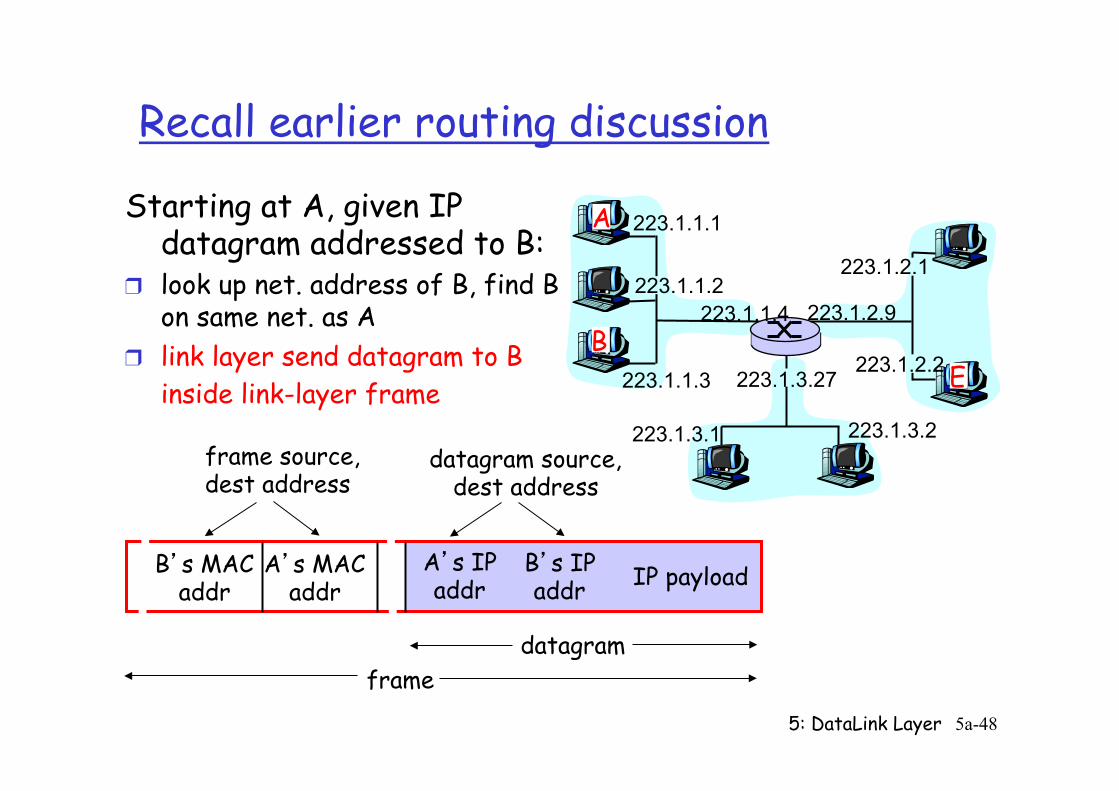
Starting at A, given IP datagram addressed to B:
❒ look up net. address of B, find B on same net. as A
❒ link layer send datagram to B inside link-layer frame
B’s MAC addr
A’s MAC addr
A’s IP addr
B’s IP addr IP payload
datagram frame
frame source, dest address
datagram source, dest address
5: DataLink Layer 5a-49
ARP: Address Resolution Protocol
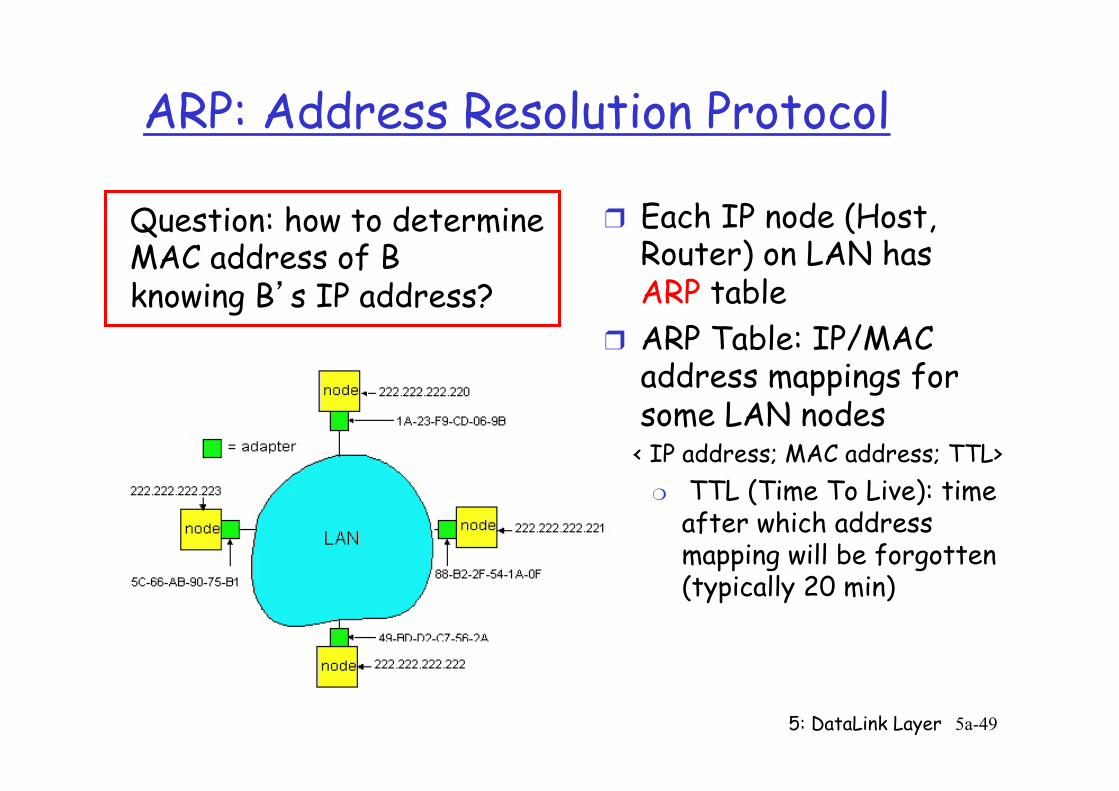
❒ Each IP node (Host, Router) on LAN has ARP table
❒ ARP Table: IP/MAC address mappings for some LAN nodes
< IP address; MAC address; TTL> ❍ TTL (Time To Live): time
after which address mapping will be forgotten (typically 20 min)
Question: how to determine MAC address of B knowing B’s IP address?
5: DataLink Layer 5a-50
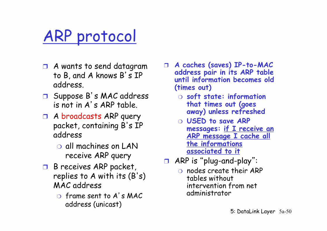
ARP protocol ❒ A wants to send datagram
to B, and A knows B’s IP address.
❒ Suppose B’s MAC address is not in A’s ARP table.
❒ A broadcasts ARP query packet, containing B's IP address ❍ all machines on LAN
receive ARP query ❒ B receives ARP packet,
replies to A with its (B's) MAC address ❍ frame sent to A’s MAC
address (unicast)
❒ A caches (saves) IP-to-MAC address pair in its ARP table until information becomes old (times out) ❍ soft state: information
that times out (goes away) unless refreshed
❍ USED to save ARP messages: if I receive an ARP message I cache all the informations associated to it
❒ ARP is “plug-and-play”: ❍ nodes create their ARP
tables without intervention from net administrator
5: DataLink Layer 5a-51
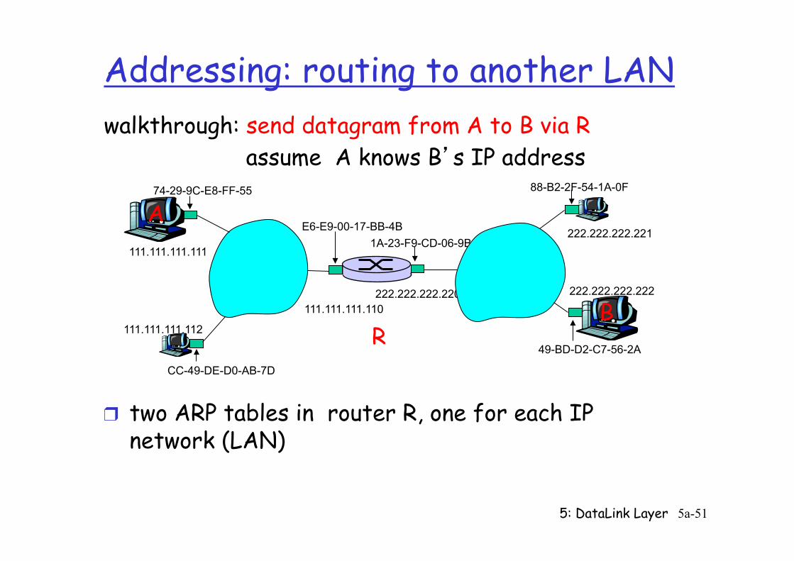
Addressing: routing to another LAN
R
1A-23-F9-CD-06-9B
222.222.222.220 111.111.111.110
E6-E9-00-17-BB-4B
CC-49-DE-D0-AB-7D
111.111.111.112
111.111.111.111
A 74-29-9C-E8-FF-55
222.222.222.221
88-B2-2F-54-1A-0F
B 222.222.222.222
49-BD-D2-C7-56-2A
walkthrough: send datagram from A to B via R assume A knows B’s IP address
❒ two ARP tables in router R, one for each IP network (LAN)
5: DataLink Layer 5a-52
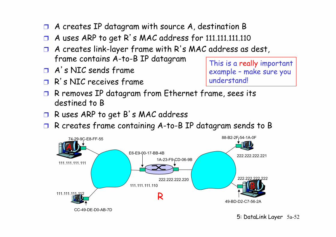
❒ A creates IP datagram with source A, destination B ❒ A uses ARP to get R’s MAC address for 111.111.111.110 ❒ A creates link-layer frame with R's MAC address as dest,
frame contains A-to-B IP datagram ❒ A’s NIC sends frame ❒ R’s NIC receives frame ❒ R removes IP datagram from Ethernet frame, sees its
destined to B ❒ R uses ARP to get B’s MAC address ❒ R creates frame containing A-to-B IP datagram sends to B
R
1A-23-F9-CD-06-9B
222.222.222.220 111.111.111.110
E6-E9-00-17-BB-4B
CC-49-DE-D0-AB-7D
111.111.111.112
111.111.111.111
A 74-29-9C-E8-FF-55
222.222.222.221
88-B2-2F-54-1A-0F
B 222.222.222.222
49-BD-D2-C7-56-2A
This is a really important example – make sure you understand!

5: DataLink Layer 5a-53
5: DataLink Layer 5a-54 5: DataLink Layer 5-54
Link Layer
❒ 5.1 Introduction and services
❒ 5.2 Error detection and correction
❒ 5.3Multiple access protocols
❒ 5.4 Link-Layer Addressing
❒ 5.5 Ethernet
❒ 5.6 Link-layer switches ❒ 5.7 PPP ❒ 5.8 Link virtualization:
MPLS ❒ 5.9 A day in the life of a
web request
5: DataLink Layer 5a-55 5: DataLink Layer 5-55
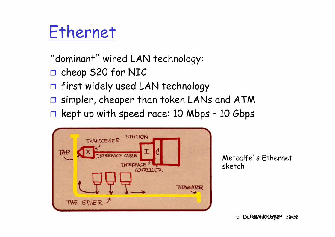
Ethernet “dominant” wired LAN technology: ❒ cheap $20 for NIC ❒ first widely used LAN technology ❒ simpler, cheaper than token LANs and ATM ❒ kept up with speed race: 10 Mbps – 10 Gbps
Metcalfe’s Ethernet sketch
5: DataLink Layer 5a-56 5: DataLink Layer 5-56
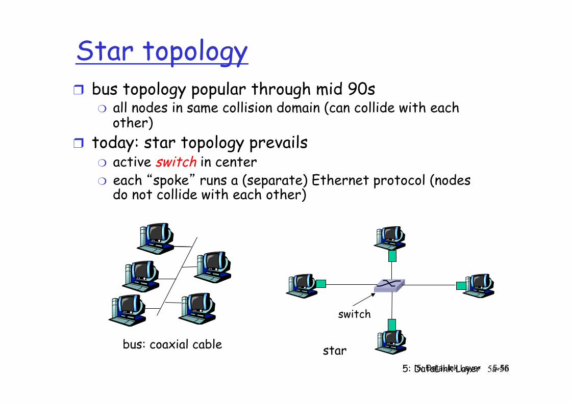
Star topology ❒ bus topology popular through mid 90s
❍ all nodes in same collision domain (can collide with each other)
❒ today: star topology prevails ❍ active switch in center ❍ each “spoke” runs a (separate) Ethernet protocol (nodes
do not collide with each other)
switch
bus: coaxial cable star
5: DataLink Layer 5a-57 5: DataLink Layer 5-57
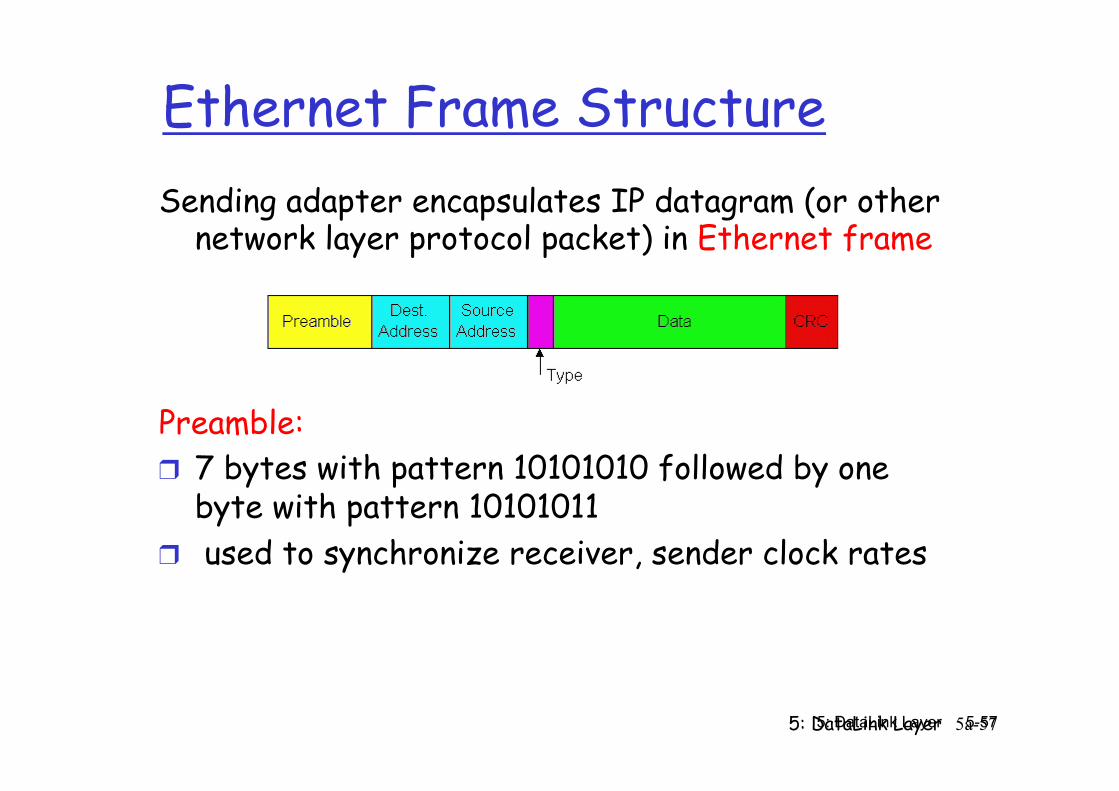
Ethernet Frame Structure Sending adapter encapsulates IP datagram (or other
network layer protocol packet) in Ethernet frame
Preamble: ❒ 7 bytes with pattern 10101010 followed by one
byte with pattern 10101011 ❒ used to synchronize receiver, sender clock rates
5: DataLink Layer 5a-58 5: DataLink Layer 5-58
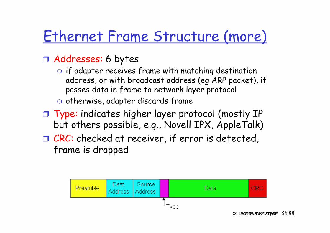
Ethernet Frame Structure (more) ❒ Addresses: 6 bytes
❍ if adapter receives frame with matching destination address, or with broadcast address (eg ARP packet), it passes data in frame to network layer protocol
❍ otherwise, adapter discards frame ❒ Type: indicates higher layer protocol (mostly IP
but others possible, e.g., Novell IPX, AppleTalk) ❒ CRC: checked at receiver, if error is detected,
frame is dropped
5: DataLink Layer 5a-59 5: DataLink Layer 5-59
Ethernet: Unreliable, connectionless
❒ connectionless: No handshaking between sending and receiving NICs
❒ unreliable: receiving NIC doesn’t send acks or nacks to sending NIC ❍ stream of datagrams passed to network layer can have gaps
(missing datagrams) ❍ gaps will be filled if app is using TCP ❍ otherwise, app will see gaps
❒ Ethernet’s MAC protocol: unslotted CSMA/CD
5: DataLink Layer 5a-60 5: DataLink Layer 5-60
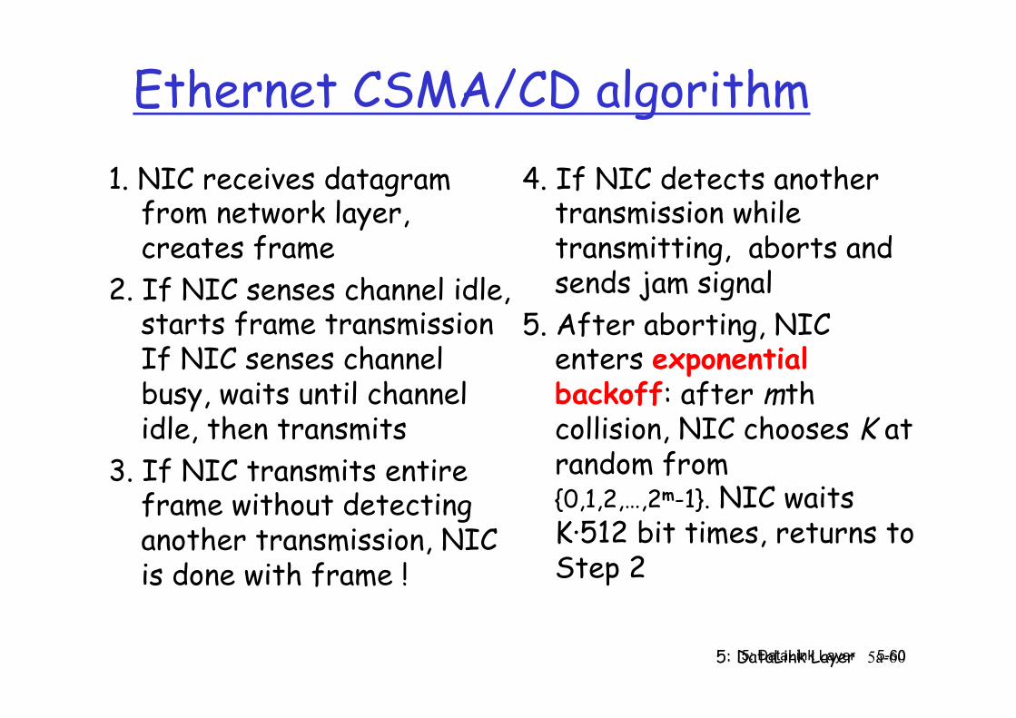
Ethernet CSMA/CD algorithm 1. NIC receives datagram
from network layer, creates frame
2. If NIC senses channel idle, starts frame transmission If NIC senses channel busy, waits until channel idle, then transmits
3. If NIC transmits entire frame without detecting another transmission, NIC is done with frame !
4. If NIC detects another transmission while transmitting, aborts and sends jam signal
5. After aborting, NIC enters exponential backoff: after mth collision, NIC chooses K at random from {0,1,2,…,2m-1}. NIC waits K·512 bit times, returns to Step 2
5: DataLink Layer 5a-61 5: DataLink Layer 5-61
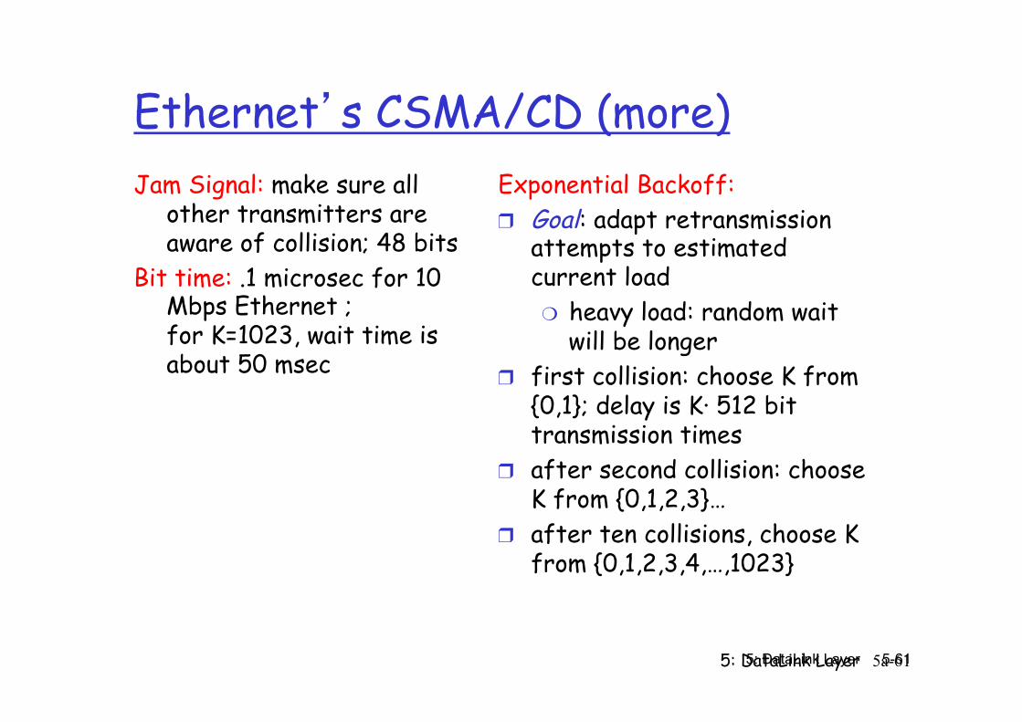
Ethernet’s CSMA/CD (more) Jam Signal: make sure all
other transmitters are aware of collision; 48 bits
Bit time: .1 microsec for 10 Mbps Ethernet ; for K=1023, wait time is about 50 msec
Exponential Backoff: ❒ Goal: adapt retransmission
attempts to estimated current load ❍ heavy load: random wait
will be longer ❒ first collision: choose K from
{0,1}; delay is K· 512 bit transmission times
❒ after second collision: choose K from {0,1,2,3}…
❒ after ten collisions, choose K from {0,1,2,3,4,…,1023}
5: DataLink Layer 5a-62 5: DataLink Layer 5-62
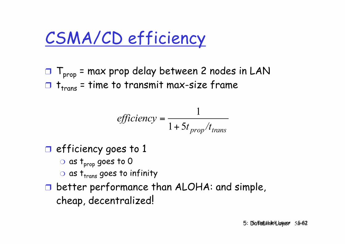
CSMA/CD efficiency
❒ Tprop = max prop delay between 2 nodes in LAN ❒ ttrans = time to transmit max-size frame
❒ efficiency goes to 1 ❍ as tprop goes to 0 ❍ as ttrans goes to infinity
❒ better performance than ALOHA: and simple, cheap, decentralized!
transprop /ttefficiency
511
+=
5: DataLink Layer 5a-63 5: DataLink Layer 5-63
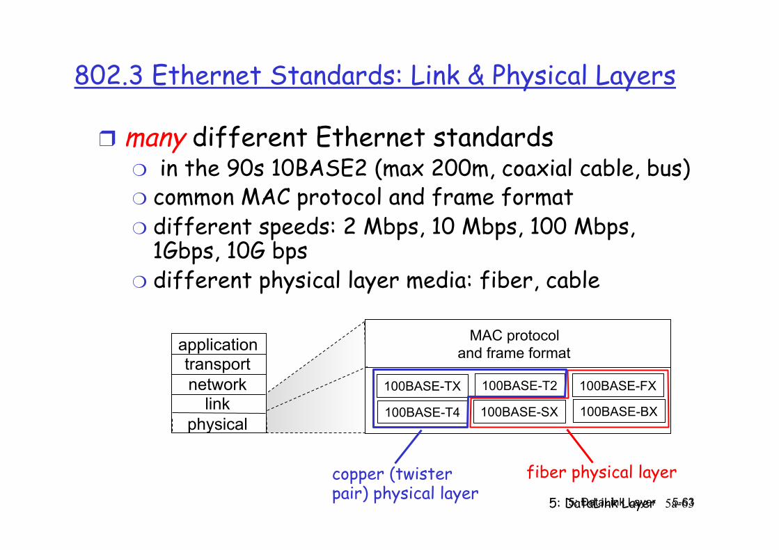
802.3 Ethernet Standards: Link & Physical Layers
❒ many different Ethernet standards ❍ in the 90s 10BASE2 (max 200m, coaxial cable, bus) ❍ common MAC protocol and frame format ❍ different speeds: 2 Mbps, 10 Mbps, 100 Mbps,
1Gbps, 10G bps ❍ different physical layer media: fiber, cable
application transport network
link physical
MAC protocol and frame format
100BASE-TX
100BASE-T4
100BASE-FX 100BASE-T2
100BASE-SX 100BASE-BX
fiber physical layer copper (twister pair) physical layer
5: DataLink Layer 5a-64 5: DataLink Layer 5-64
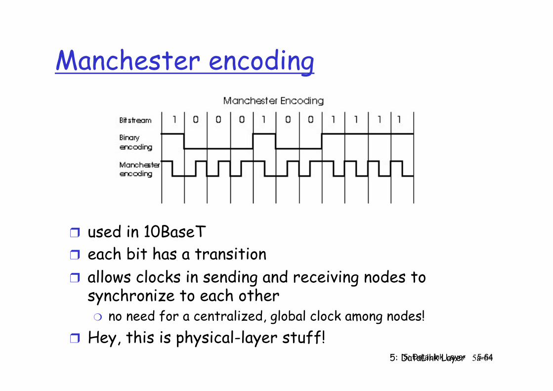
Manchester encoding
❒ used in 10BaseT ❒ each bit has a transition ❒ allows clocks in sending and receiving nodes to
synchronize to each other ❍ no need for a centralized, global clock among nodes!
❒ Hey, this is physical-layer stuff!