Embed Size (px)
Citation preview
Chapter 5 Data Link Layer
Computer Networking: A Top Down Approach 6th edition Jim Kurose, Keith Ross Addison-Wesley March 2012
Network Layer 4-1
Reti degli Elaboratori Canale AL Prof.ssa Chiara Petrioli a.a. 2013/2014 We thank for the support material Prof. Kurose-Ross All material copyright 1996-2012 J.F Kurose and K.W. Ross, All Rights Reserved
5: DataLink Layer 5a-2
Chapter 5: The Data Link Layer Our goals: ❒ understand principles behind data link layer
services: ❍ error detection, correction ❍ sharing a broadcast channel: multiple access ❍ link layer addressing ❍ reliable data transfer, flow control: done!
❒ instantiation and implementation of various link layer technologies
5: DataLink Layer 5a-3
Link Layer
❒ 5.1 Introduction and services
❒ 5.2 Error detection and correction
❒ 5.3Multiple access protocols
❒ 5.4 Link-layer Addressing
❒ 5.5 Ethernet
❒ 5.6 Link-layer switches ❒ 5.7 PPP ❒ 5.8 Link virtualization:
MPLS ❒ 5.9 A day in the life of a
web request
5: DataLink Layer 5a-4
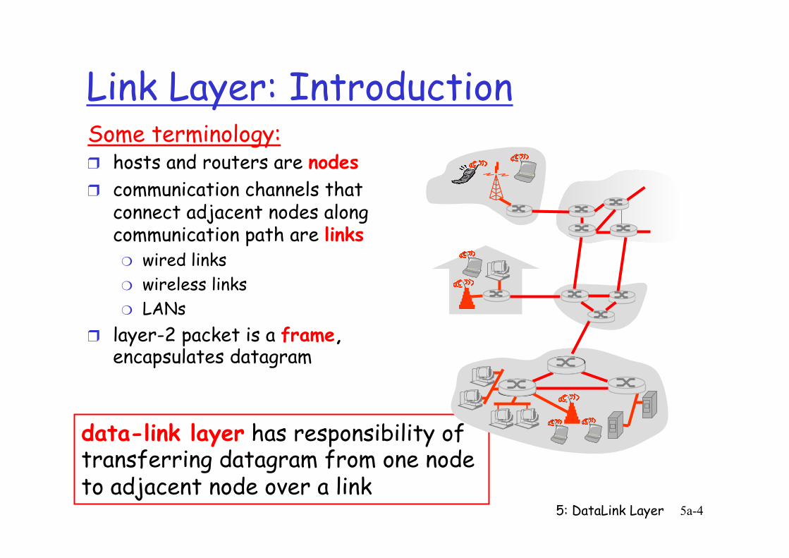
Link Layer: Introduction Some terminology: ❒ hosts and routers are nodes ❒ communication channels that
connect adjacent nodes along communication path are links ❍ wired links ❍ wireless links ❍ LANs
❒ layer-2 packet is a frame, encapsulates datagram
data-link layer has responsibility of transferring datagram from one node to adjacent node over a link
5: DataLink Layer 5a-5
Link layer: context ❒ datagram transferred by
different link protocols over different links: ❍ e.g., Ethernet on first link,
frame relay on intermediate links, 802.11 on last link
❒ each link protocol provides different services ❍ e.g., may or may not
provide rdt over link
transportation analogy ❒ trip from Princeton to
Lausanne ❍ limo: Princeton to JFK ❍ plane: JFK to Geneva ❍ train: Geneva to Lausanne
❒ tourist = datagram ❒ transport segment =
communication link ❒ transportation mode = link
layer protocol ❒ travel agent = routing
algorithm
5: DataLink Layer 5a-6
Link Layer Services
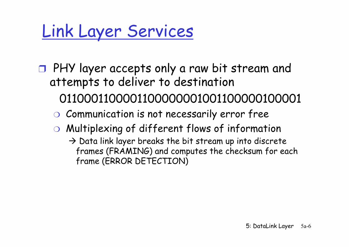
❒ PHY layer accepts only a raw bit stream and attempts to deliver to destination
0110001100001100000001001100000100001 ❍ Communication is not necessarily error free ❍ Multiplexing of different flows of information
à Data link layer breaks the bit stream up into discrete frames (FRAMING) and computes the checksum for each frame (ERROR DETECTION)
5: DataLink Layer 5a-7
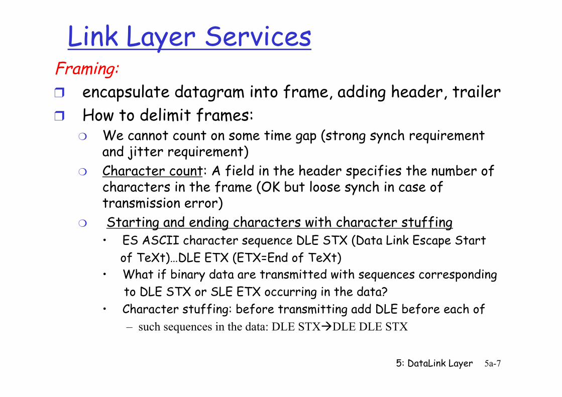
Link Layer Services Framing: ❒ encapsulate datagram into frame, adding header, trailer ❒ How to delimit frames:
❍ We cannot count on some time gap (strong synch requirement and jitter requirement)
❍ Character count: A field in the header specifies the number of characters in the frame (OK but loose synch in case of transmission error)
❍ Starting and ending characters with character stuffing • ES ASCII character sequence DLE STX (Data Link Escape Start of TeXt)…DLE ETX (ETX=End of TeXt) • What if binary data are transmitted with sequences corresponding to DLE STX or SLE ETX occurring in the data? • Character stuffing: before transmitting add DLE before each of
– such sequences in the data: DLE STXàDLE DLE STX
5: DataLink Layer 5a-8
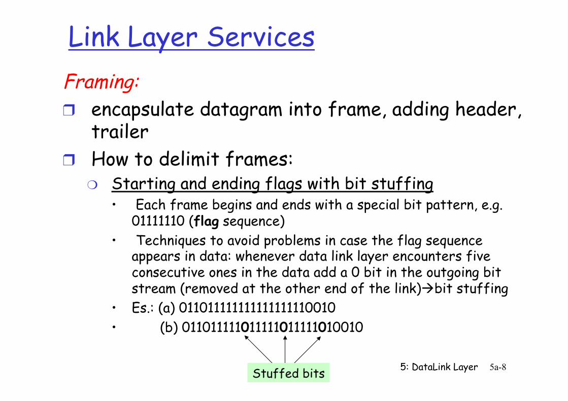
Link Layer Services Framing: ❒ encapsulate datagram into frame, adding header,
trailer ❒ How to delimit frames:
❍ Starting and ending flags with bit stuffing • Each frame begins and ends with a special bit pattern, e.g.
01111110 (flag sequence) • Techniques to avoid problems in case the flag sequence
appears in data: whenever data link layer encounters five consecutive ones in the data add a 0 bit in the outgoing bit stream (removed at the other end of the link)àbit stuffing
• Es.: (a) 011011111111111111110010 • (b) 011011111011111011111010010
Stuffed bits
5: DataLink Layer 5a-9
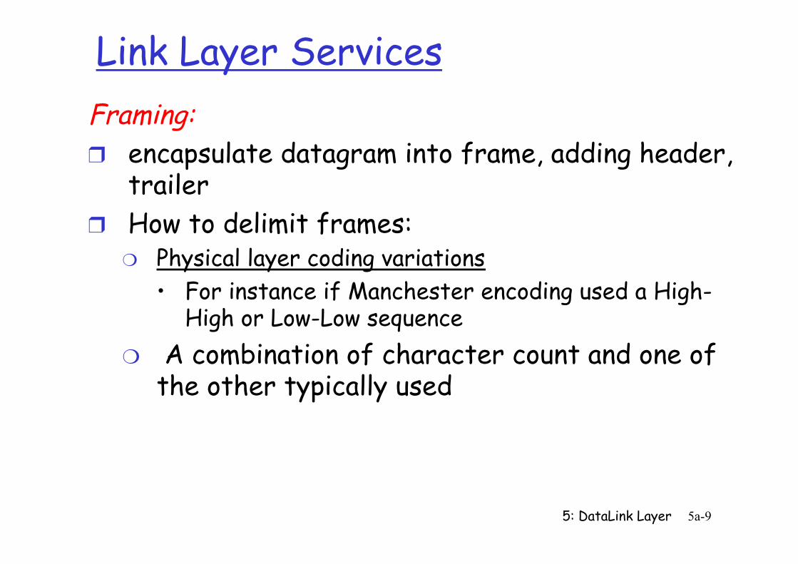
Link Layer Services Framing: ❒ encapsulate datagram into frame, adding header,
trailer ❒ How to delimit frames:
❍ Physical layer coding variations • For instance if Manchester encoding used a High-
High or Low-Low sequence ❍ A combination of character count and one of
the other typically used
5: DataLink Layer 5-10
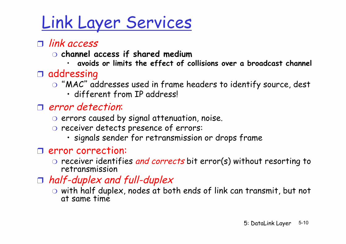
Link Layer Services ❒ link access
❍ channel access if shared medium • avoids or limits the effect of collisions over a broadcast channel
❒ addressing ❍ “MAC” addresses used in frame headers to identify source, dest
• different from IP address! ❒ error detection:
❍ errors caused by signal attenuation, noise. ❍ receiver detects presence of errors:
• signals sender for retransmission or drops frame ❒ error correction:
❍ receiver identifies and corrects bit error(s) without resorting to retransmission
❒ half-duplex and full-duplex ❍ with half duplex, nodes at both ends of link can transmit, but not
at same time
5: DataLink Layer 5a-11
Link Layer Services (more)
❒ reliable delivery between adjacent nodes ❍ we learned how to do this already (chapter 3)! ❍ seldom used on low bit-error link (fiber, some
twisted pair) ❍ wireless links: high error rates
• Q: why both link-level and end-end reliability?
❒ flow control: ❍ pacing between adjacent sending and receiving
nodes
5: DataLink Layer 5a-12
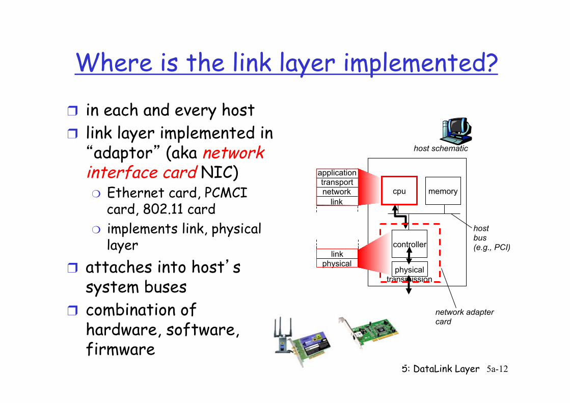
Where is the link layer implemented?
❒ in each and every host ❒ link layer implemented in “adaptor” (aka network interface card NIC) ❍ Ethernet card, PCMCI
card, 802.11 card ❍ implements link, physical
layer ❒ attaches into host’s
system buses ❒ combination of
hardware, software, firmware
controller
physical transmission
cpu memory
host bus (e.g., PCI)
network adapter card
host schematic
application transport network
link
link physical
5: DataLink Layer 5a-13
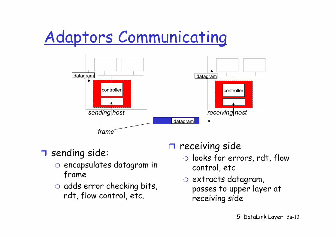
Adaptors Communicating
❒ sending side: ❍ encapsulates datagram in
frame ❍ adds error checking bits,
rdt, flow control, etc.
❒ receiving side ❍ looks for errors, rdt, flow
control, etc ❍ extracts datagram,
passes to upper layer at receiving side
controller controller
sending host receiving host
datagram datagram
datagram
frame
5: DataLink Layer 5a-14
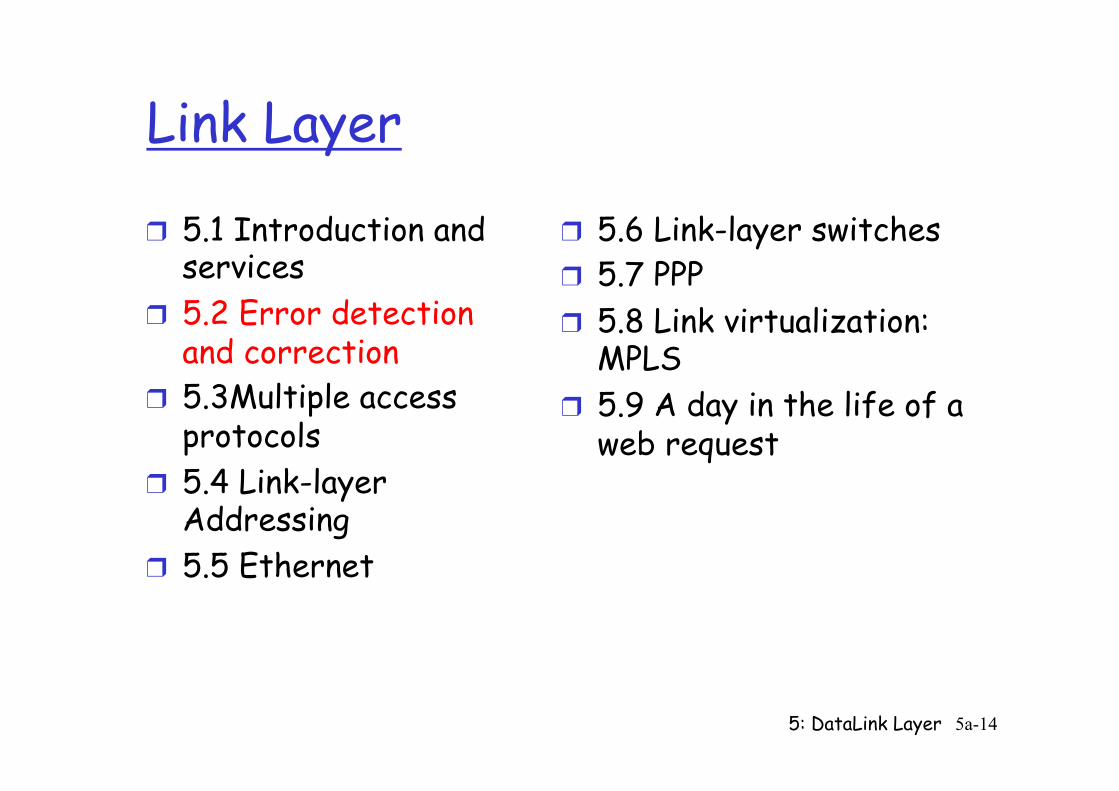
Link Layer
❒ 5.1 Introduction and services
❒ 5.2 Error detection and correction
❒ 5.3Multiple access protocols
❒ 5.4 Link-layer Addressing
❒ 5.5 Ethernet
❒ 5.6 Link-layer switches ❒ 5.7 PPP ❒ 5.8 Link virtualization:
MPLS ❒ 5.9 A day in the life of a
web request
5: DataLink Layer 5a-15
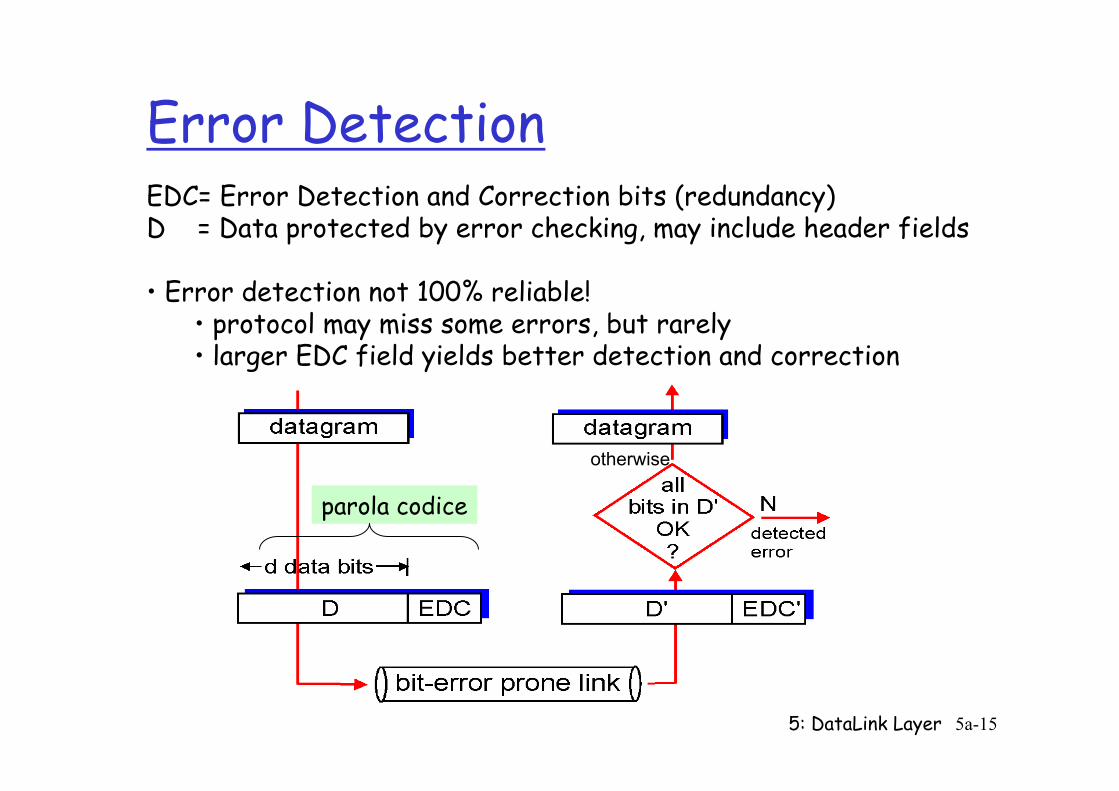
Error Detection EDC= Error Detection and Correction bits (redundancy) D = Data protected by error checking, may include header fields • Error detection not 100% reliable!
• protocol may miss some errors, but rarely • larger EDC field yields better detection and correction
otherwise
parola codice
5: DataLink Layer 5a-16
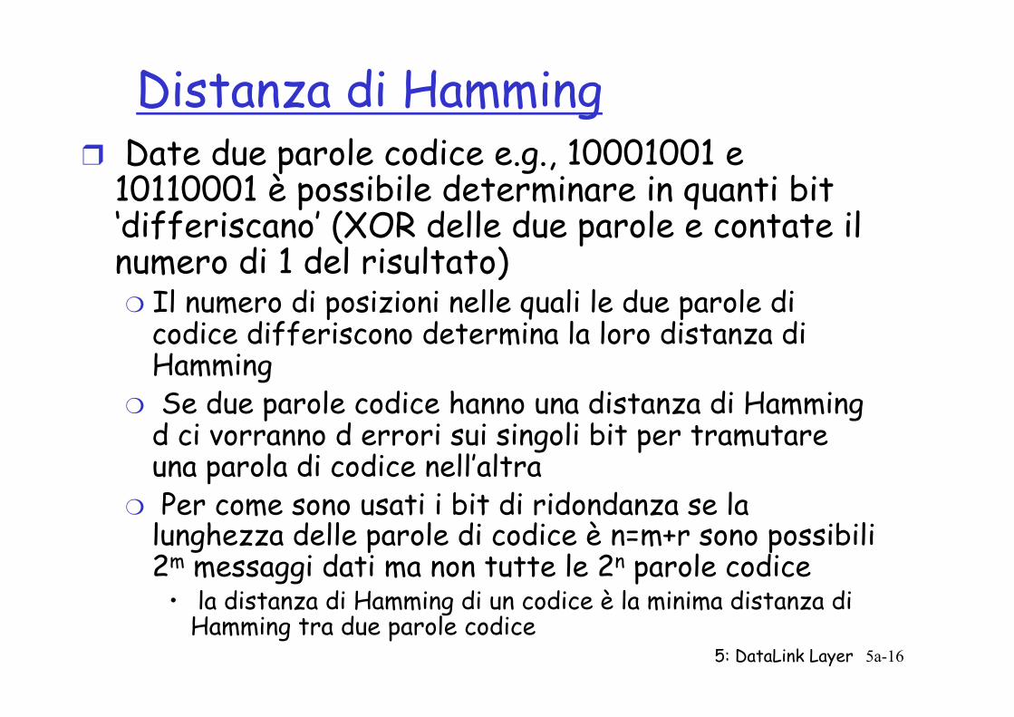
Distanza di Hamming ❒ Date due parole codice e.g., 10001001 e
10110001 è possibile determinare in quanti bit ‘differiscano’ (XOR delle due parole e contate il numero di 1 del risultato) ❍ Il numero di posizioni nelle quali le due parole di
codice differiscono determina la loro distanza di Hamming
❍ Se due parole codice hanno una distanza di Hamming d ci vorranno d errori sui singoli bit per tramutare una parola di codice nell’altra
❍ Per come sono usati i bit di ridondanza se la lunghezza delle parole di codice è n=m+r sono possibili 2m messaggi dati ma non tutte le 2n parole codice
• la distanza di Hamming di un codice è la minima distanza di Hamming tra due parole codice
5: DataLink Layer 5a-17
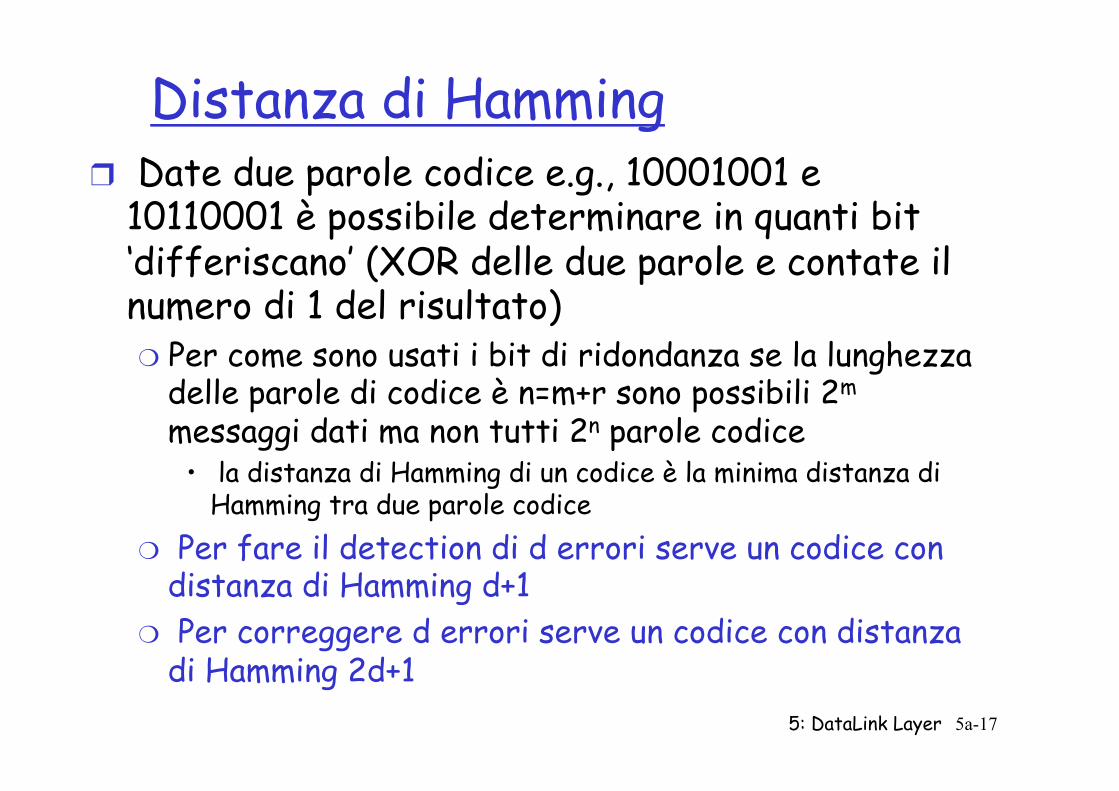
Distanza di Hamming ❒ Date due parole codice e.g., 10001001 e
10110001 è possibile determinare in quanti bit ‘differiscano’ (XOR delle due parole e contate il numero di 1 del risultato) ❍ Per come sono usati i bit di ridondanza se la lunghezza
delle parole di codice è n=m+r sono possibili 2m messaggi dati ma non tutti 2n parole codice
• la distanza di Hamming di un codice è la minima distanza di Hamming tra due parole codice
❍ Per fare il detection di d errori serve un codice con distanza di Hamming d+1
❍ Per correggere d errori serve un codice con distanza di Hamming 2d+1
5: DataLink Layer 5a-18
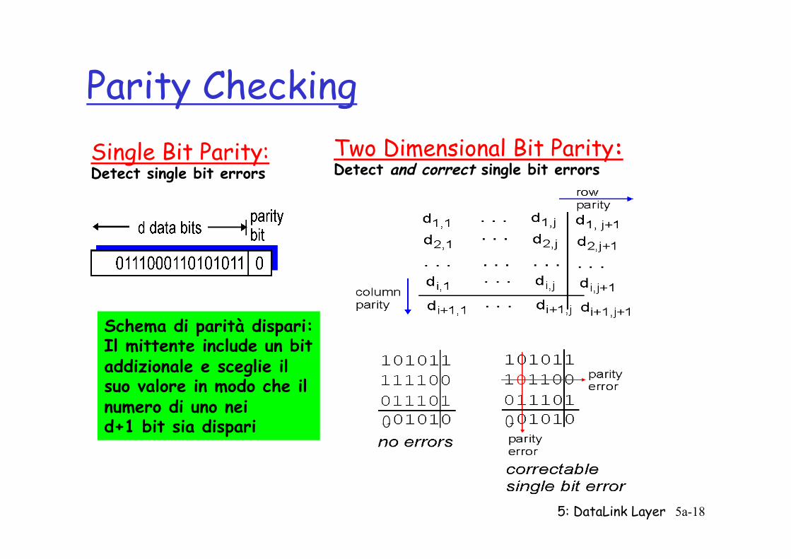
Parity Checking Single Bit Parity: Detect single bit errors
Two Dimensional Bit Parity: Detect and correct single bit errors
0 0
Schema di parità dispari: Il mittente include un bit addizionale e sceglie il suo valore in modo che il numero di uno nei d+1 bit sia dispari

5: DataLink Layer 5a-19
Parity Checking Single Bit Parity: Detect single bit errors
Two Dimensional Bit Parity: Detect and correct single bit errors
0 0
Schema di parità dispari: Il mittente include un bit addizionale e sceglie il suo valore in modo che il numero di uno nei d+1 bit sia dispari
Schemi semplici possono essere sufficienti nel caso di errori casuali Cosa si può fare nel caso di errori a burst? • Maggiore ridondanza • Interleaving
5: DataLink Layer 5a-20
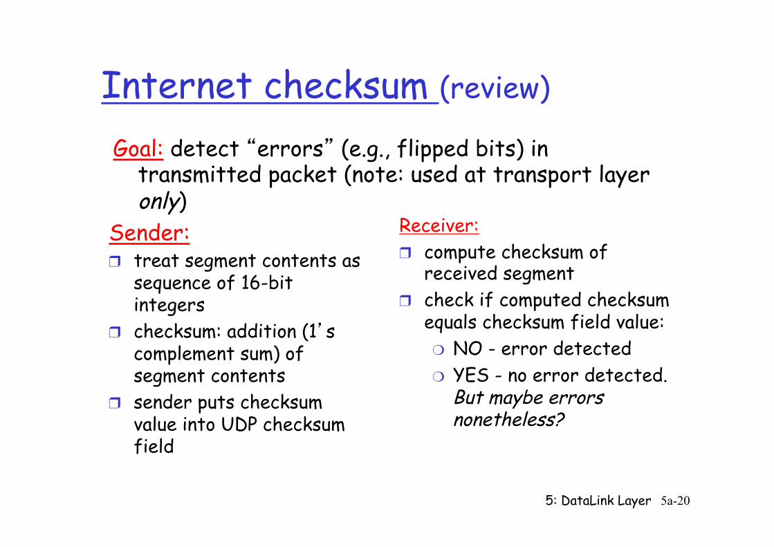
Internet checksum (review)
Sender: ❒ treat segment contents as
sequence of 16-bit integers
❒ checksum: addition (1’s complement sum) of segment contents
❒ sender puts checksum value into UDP checksum field
Receiver: ❒ compute checksum of
received segment ❒ check if computed checksum
equals checksum field value: ❍ NO - error detected ❍ YES - no error detected.
But maybe errors nonetheless?
Goal: detect “errors” (e.g., flipped bits) in transmitted packet (note: used at transport layer only)
5: DataLink Layer 5a-21
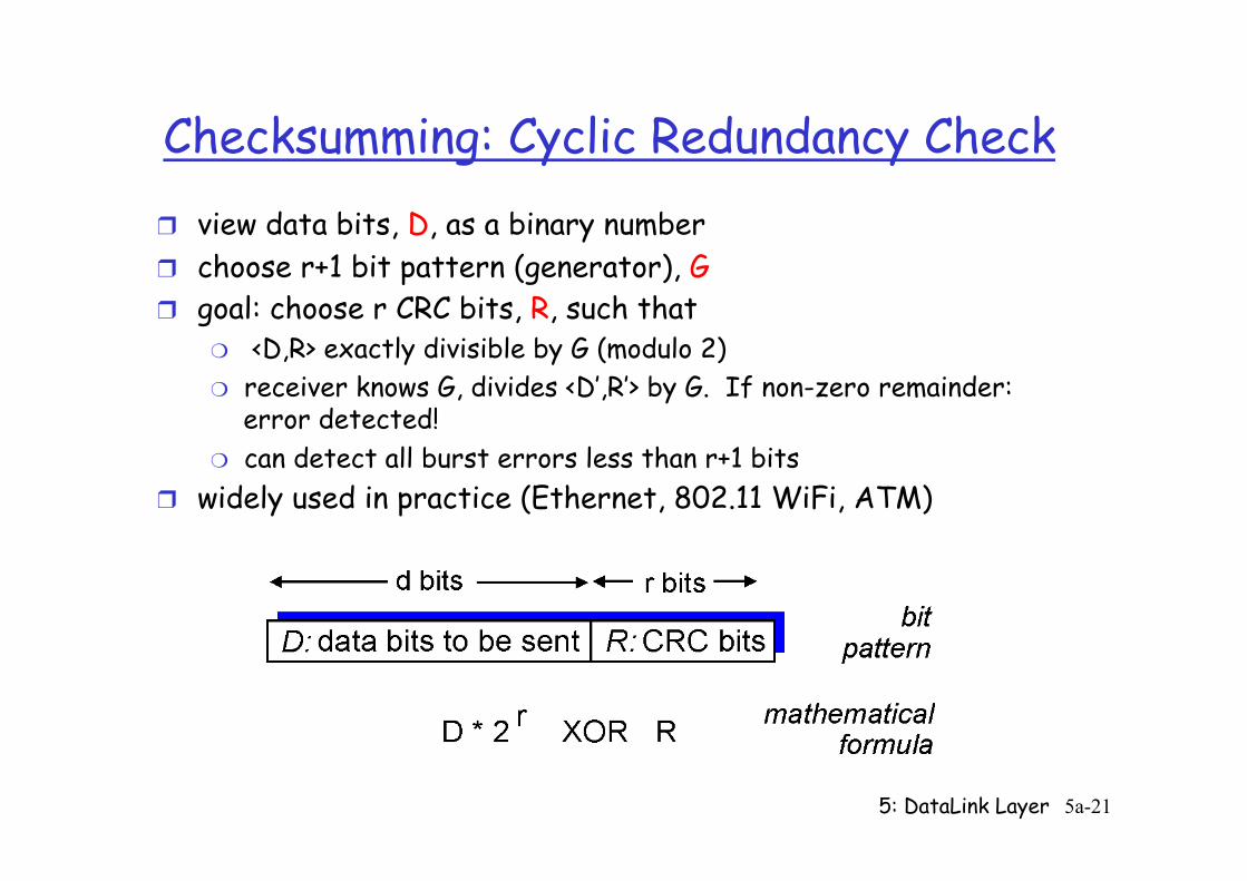
Checksumming: Cyclic Redundancy Check ❒ view data bits, D, as a binary number ❒ choose r+1 bit pattern (generator), G ❒ goal: choose r CRC bits, R, such that
❍ <D,R> exactly divisible by G (modulo 2) ❍ receiver knows G, divides <D’,R’> by G. If non-zero remainder:
error detected! ❍ can detect all burst errors less than r+1 bits
❒ widely used in practice (Ethernet, 802.11 WiFi, ATM)
5: DataLink Layer 5a-22
CRC
❒ r è l’ordine del polinomio generatore G(x) ❒ Appendi r bit zero al messaggio M(x) che ora
corrisponde a xr M(x) ❒ dividi xrM(x) per G(x) modulo 2 ❒ Sottrai (modulo 2) il resto della divisione da
xrM(x)à si ottiene T(x), il risultato da trasmettere
❒ In ricezione controlla che il resto della divisione per G(x) sia 0
❒ Estrai la parte di messaggio M(x)
5: DataLink Layer 5a-23
Link Layer
❒ 5.1 Introduction and services
❒ 5.2 Error detection and correction
❒ 5.3Multiple access protocols
❒ 5.4 Link-layer Addressing
❒ 5.5 Ethernet
❒ 5.6 Link-layer switches ❒ 5.7 PPP ❒ 5.8 Link virtualization:
MPLS ❒ 5.9 A day in the life of a
web request
5: DataLink Layer 5a-24
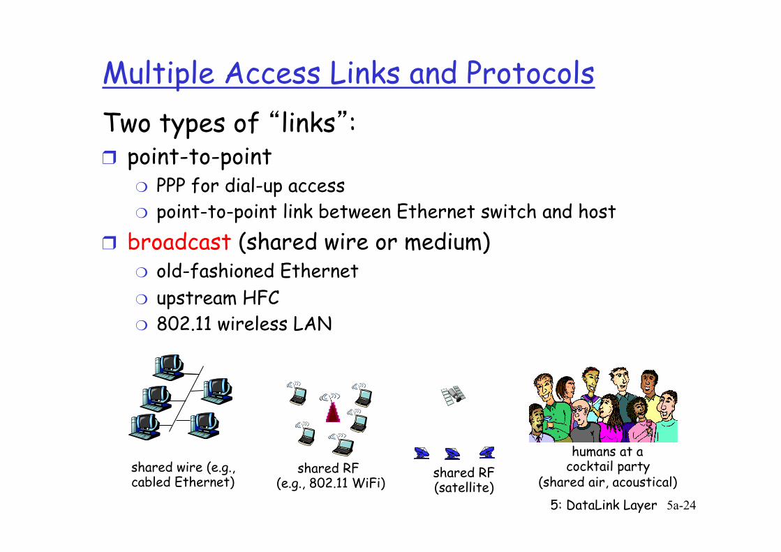
Multiple Access Links and Protocols Two types of “links”: ❒ point-to-point
❍ PPP for dial-up access ❍ point-to-point link between Ethernet switch and host
❒ broadcast (shared wire or medium) ❍ old-fashioned Ethernet ❍ upstream HFC ❍ 802.11 wireless LAN
shared wire (e.g., cabled Ethernet)
shared RF (e.g., 802.11 WiFi)
shared RF (satellite)
humans at a cocktail party
(shared air, acoustical)
5: DataLink Layer 5a-25
Multiple Access protocols ❒ single shared broadcast channel ❒ two or more simultaneous transmissions by nodes:
interference ❍ collision if node receives two or more signals at the same time
multiple access protocol ❒ distributed algorithm that determines how nodes
share channel, i.e., determine when node can transmit ❒ communication about channel sharing must use channel
itself! ❍ no out-of-band channel for coordination
5: DataLink Layer 5a-26
Ideal Multiple Access Protocol
Broadcast channel of rate R bps 1. when one node wants to transmit, it can send at
rate R. 2. when M nodes want to transmit, each can send at
average rate R/M 3. fully decentralized:
❍ no special node to coordinate transmissions ❍ no synchronization of clocks, slots
4. simple
5: DataLink Layer 5a-27
MAC Protocols: a taxonomy Three broad classes: ❒ Channel Partitioning
❍ divide channel into smaller “pieces” (time slots, frequency, code)
❍ allocate piece to node for exclusive use ❒ Random Access
❍ channel not divided, allow collisions ❍ “recover” from collisions
❒ “Taking turns” ❍ nodes take turns, but nodes with more to send can take
longer turns
5: DataLink Layer 5a-28
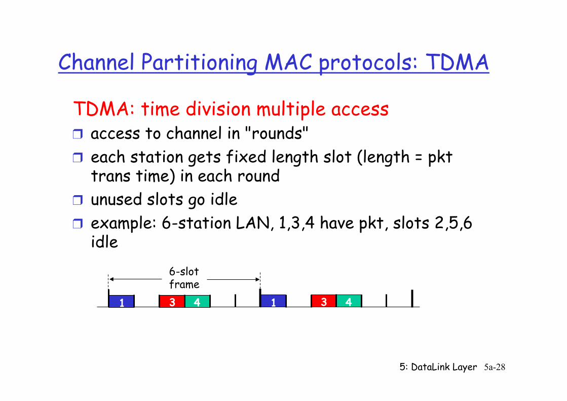
Channel Partitioning MAC protocols: TDMA TDMA: time division multiple access ❒ access to channel in "rounds" ❒ each station gets fixed length slot (length = pkt
trans time) in each round ❒ unused slots go idle ❒ example: 6-station LAN, 1,3,4 have pkt, slots 2,5,6
idle
1 3 4 1 3 4
6-slot frame
5: DataLink Layer 5a-29
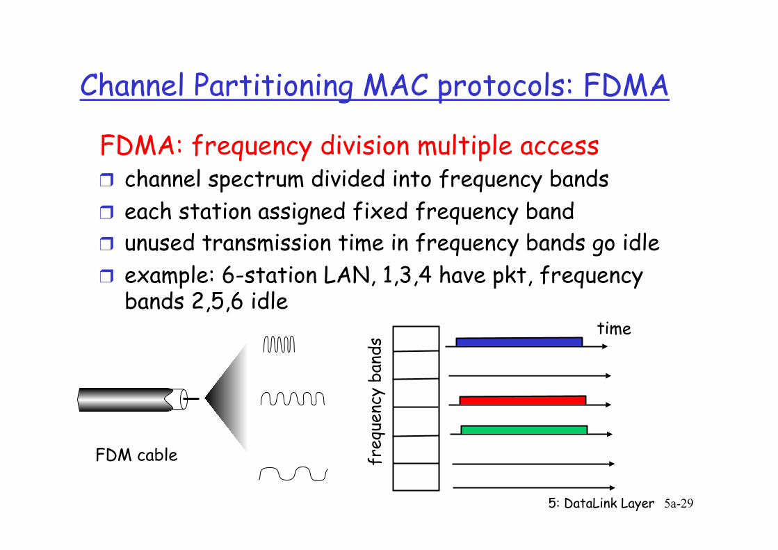
Channel Partitioning MAC protocols: FDMA FDMA: frequency division multiple access ❒ channel spectrum divided into frequency bands ❒ each station assigned fixed frequency band ❒ unused transmission time in frequency bands go idle ❒ example: 6-station LAN, 1,3,4 have pkt, frequency
bands 2,5,6 idle
freq
uenc
y ba
nds
time
FDM cable

5: DataLink Layer 5a-30
TDMA/FDMA Vs. Ideal Multiple Access Protocol Broadcast channel of rate R bps 1. when one node wants to transmit, it can send at
rate R. à NOT MET BY TDMA/FDMA 2. when M nodes want to transmit, each can send at
average rate R/M à MET BY TDMA/FDMA IN CASE M=N
3. fully decentralized: ❍ no special node to coordinate transmissions ❍ no synchronization of clocks, slots
4. simple
5: DataLink Layer 5a-31
Random Access Protocols
❒ When node has packet to send ❍ transmit at full channel data rate R. ❍ no a priori coordination among nodes
❒ two or more transmitting nodes ➜ “collision”, ❒ random access MAC protocol specifies:
❍ how to detect collisions ❍ how to recover from collisions (e.g., via delayed
retransmissions) ❒ Examples of random access MAC protocols:
❍ slotted ALOHA ❍ ALOHA ❍ CSMA, CSMA/CD, CSMA/CA
5: DataLink Layer 5a-32
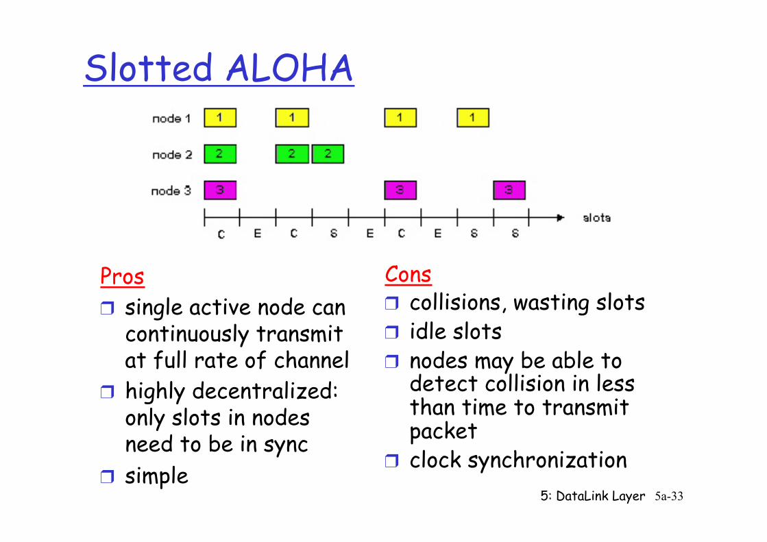
Slotted ALOHA
Assumptions: ❒ all frames same size ❒ time divided into equal
size slots (time to transmit 1 frame)
❒ nodes start to transmit only slot beginning
❒ nodes are synchronized ❒ if 2 or more nodes
transmit in slot, all nodes detect collision
Operation: ❒ when node obtains fresh
frame, transmits in next slot ❍ if no collision: node can
send new frame in next slot
❍ if collision: node retransmits frame in each subsequent slot with prob. p until success
5: DataLink Layer 5a-33
Slotted ALOHA
Pros ❒ single active node can
continuously transmit at full rate of channel
❒ highly decentralized: only slots in nodes need to be in sync
❒ simple
Cons ❒ collisions, wasting slots ❒ idle slots ❒ nodes may be able to
detect collision in less than time to transmit packet
❒ clock synchronization
5: DataLink Layer 5a-34
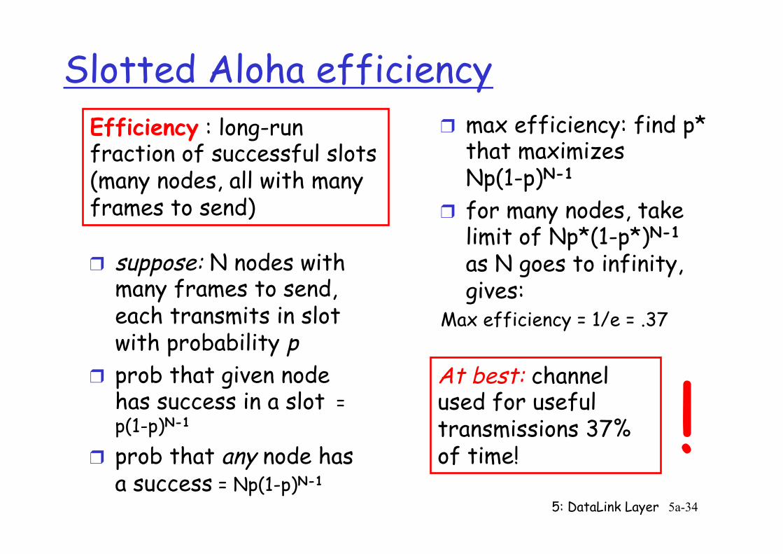
Slotted Aloha efficiency
❒ suppose: N nodes with many frames to send, each transmits in slot with probability p
❒ prob that given node has success in a slot = p(1-p)N-1
❒ prob that any node has a success = Np(1-p)N-1
❒ max efficiency: find p* that maximizes Np(1-p)N-1
❒ for many nodes, take limit of Np*(1-p*)N-1
as N goes to infinity, gives:
Max efficiency = 1/e = .37
Efficiency : long-run fraction of successful slots (many nodes, all with many frames to send)
At best: channel used for useful transmissions 37% of time! !
5: DataLink Layer 5a-35
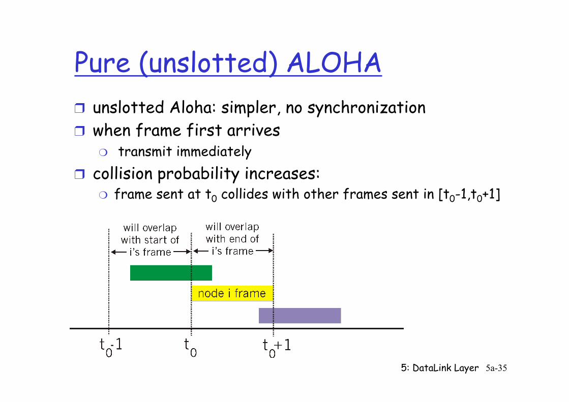
Pure (unslotted) ALOHA ❒ unslotted Aloha: simpler, no synchronization ❒ when frame first arrives
❍ transmit immediately ❒ collision probability increases:
❍ frame sent at t0 collides with other frames sent in [t0-1,t0+1]
5: DataLink Layer 5a-36
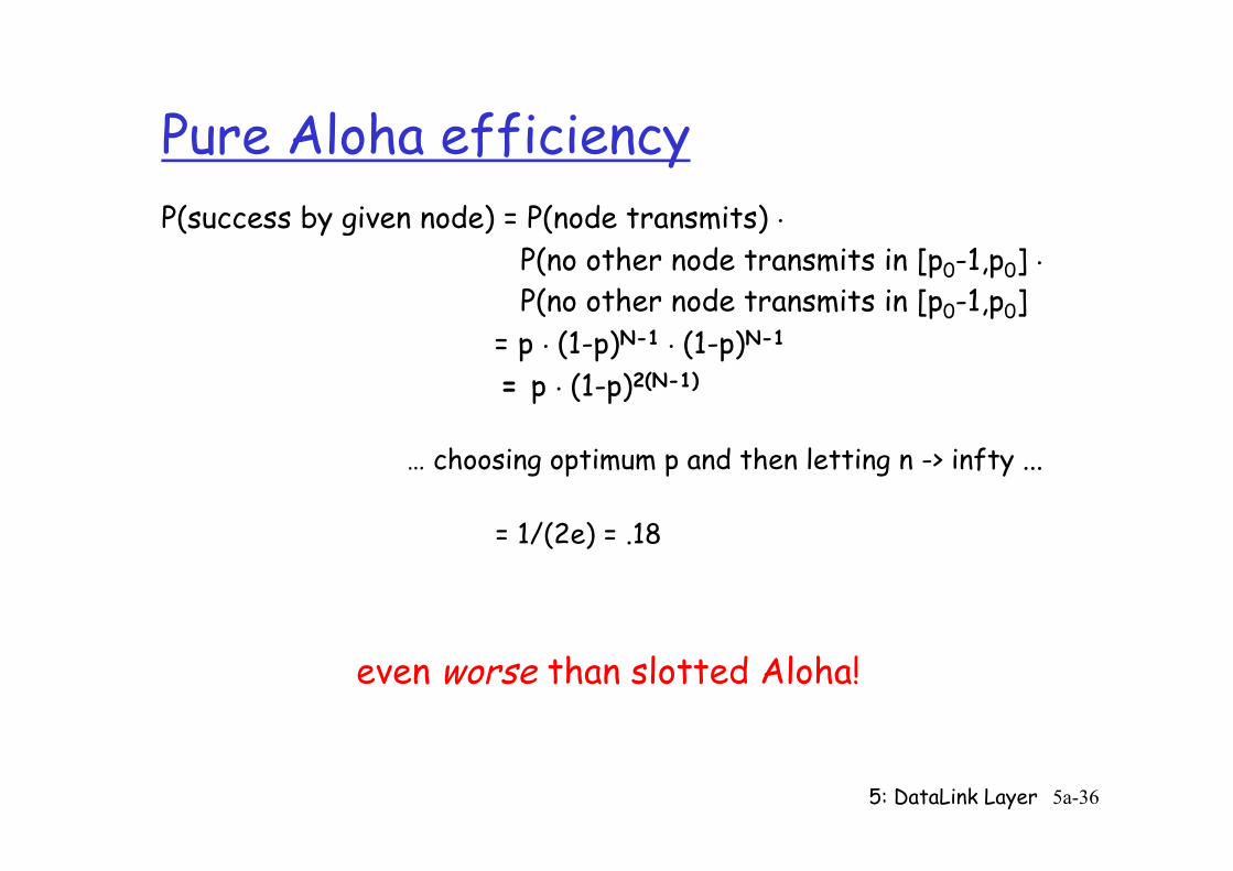
Pure Aloha efficiency P(success by given node) = P(node transmits) . P(no other node transmits in [p0-1,p0] . P(no other node transmits in [p0-1,p0] = p . (1-p)N-1 . (1-p)N-1
= p . (1-p)2(N-1) … choosing optimum p and then letting n -> infty ...
= 1/(2e) = .18
even worse than slotted Aloha!